

Page 1
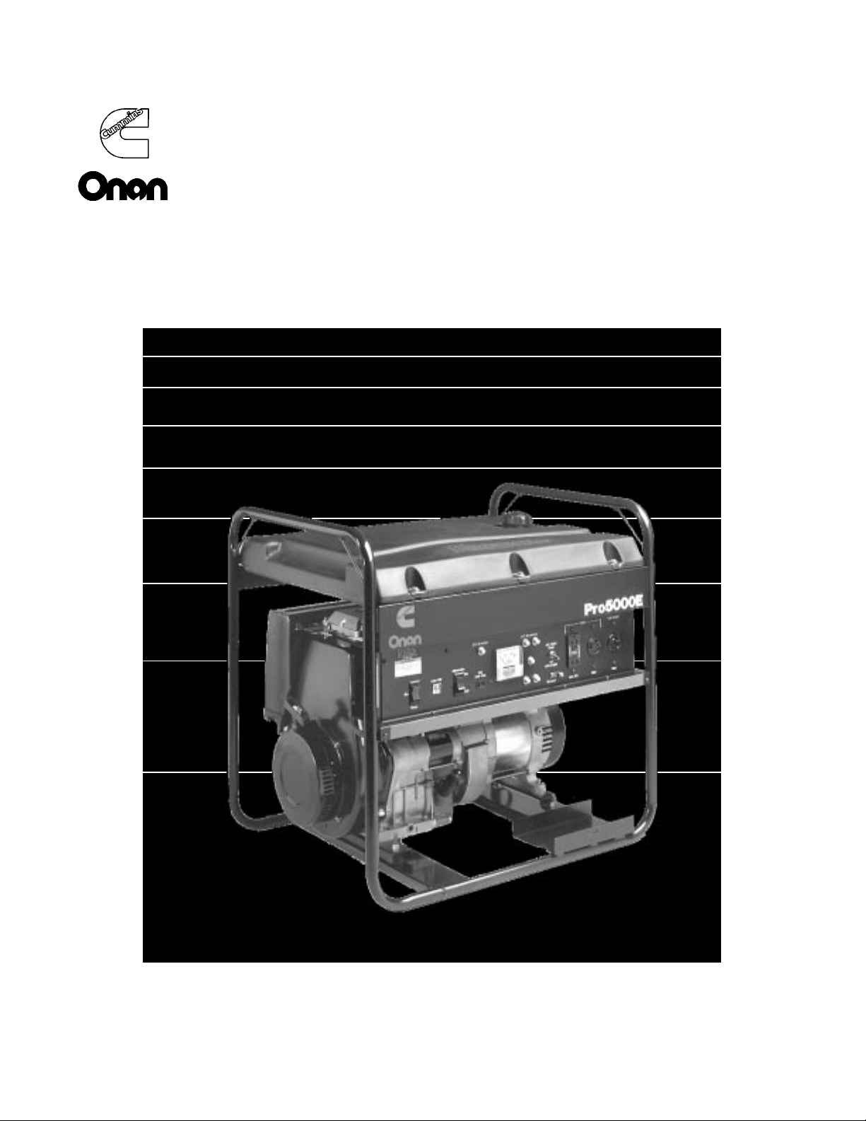
Operator’s Manual
Models
EGHAM, EGHEM, EGHAA, EGHAB, EGHEB
Portable Generator Sets (Pro Series)
965-0100Printed in U.S.A. 10-95
Page 2

Safety Precautions
Redistribution or publication of this document,
by any means, is strictly prohibited.
Before operating the generator set, read the Operator’s
Manual and become familiar with it and your equipment. Safe
and efficient operation can be achieved only if the equipment is properly operated and maintained. Many accidents
are caused by failure to follow fundamental rules and precautions.
The following symbols, found throughout this manual, alert you
to potentially dangerous conditions to the operator, service personnel, or the equipment.
This symbol warns of immediate hazards which will result in severe personal injury or
death.
This symbol refers to a hazard or unsafe
practice which can result in severe personal injury or
death.
This symbol refers to a hazard or unsafe
practice which can result in personal injury or product or property damage.
Fuels, electrical equipment, batteries, exhaust gases and moving parts present potential hazards that could result in severe
personal injury. Take care in following these recommended
procedures.
FUEL AND FUMES ARE FLAMMABLE. Fire, explosion, and
severe personal injury can result from improper practices.
• DO NOT fill fuel tanks with the engine running. Fuel con-
tact with hot engine or exhaust is a potential fire hazard.
• DO NOT SMOKE OR ALLOW AN OPEN FLAME near the
generator set or fuel tank.
• DO NOT store or transport the generator set without first
removing the fuel from the fuel tank.
• DO NOT SMOKE while servicing batteries. Lead acid bat-
teries emit a highly explosive hydrogen gas that can be ignited by electrical arcing or by smoking.
EXHAUST GASES ARE DEADLY
•
Engine exhaust contains CARBON MONOXIDE, a dangerous gas that is potentially lethal. Avoid carbon monoxide inhalation by operating the generator set outdoors
where exhaust gases can be discharged directly into the
open air.
• Do not operate the generator set in any type of enclosure
that could allow exhaust gases to accumulate. Direct exhaust gas away from areas where people are gathered
and away from buildings or enclosures.
MOVING PARTS CAN CAUSE SEVERE
PERSONAL INJURY OR DEATH
•
Before performing any maintenance on the generator set,
disconnect the spark plug wire (and the starting battery
negative [-] cable on electric start sets) to prevent accidental starting.
• Keep hands away from moving parts.
• Do not wear loose clothing or jewelry while servicing any
part of the generator set. Loose clothing and jewelry can
become caught in moving parts. Jewelry can short out
electrical contacts and cause shock or burning.
• Make sure that fasteners on the generator set are secure.
Tighten supports and clamps, keep guards in position over
fans, drive belts, etc.
• If adjustments must be made while the generator set is
running, use extreme caution around hot manifolds and
moving parts, etc.
ELECTRICAL SHOCK CAN CAUSE
SEVERE PERSONAL INJURY OR DEATH
•
Disconnect starting battery before removing protective
shields or touching electrical equipment. Use rubber insulative mats placed on dry wood platforms over floors that
are metal or concrete when around electrical equipment.
Do not wear damp clothing (particularly wet shoes) or allow skin surface to be damp when handling electrical
equipment.
• Use extreme caution when working on electrical compo-
nents. High voltages can cause injury or death. DO NOT
tamper with interlocks.
• Follow all applicable state and local electrical codes. Have
all electrical installations performed by a qualified licensed
electrician. Tag open switches to avoid accidental closure.
• DO NOT CONNECT GENERATOR SET DIRECTLY TO
ANY BUILDING ELECTRICAL SYSTEM. Hazardous volt−
ages can flow from the generator set into the utility line.
This creates a potential for electrocution or property dam−
age. Connect only through an approved device and after
building main switch is open. Consult an electrician in re−
gard to emergency power use.
GENERAL SAFETY PRECAUTIONS
Have a fire extinguisher nearby. Maintain extinguisher
•
properly and become familiar with its use. Extinguishers
rated ABC by the NFPA are appropriate for all applications. Consult the local fire department for the correct type
of extinguisher for various applications.
• Benzene and lead, found in some gasoline, have been
identified by some state and federal agencies as causing
cancer or reproductive toxicity. When checking, draining
or adding gasoline, take care not to ingest, breathe the
fumes, or contact gasoline.
• Used engine oils have been identified by some state or
federal agencies as causing cancer or reproductive toxicity. When checking or changing engine oil, take care not to
ingest, breathe the fumes, or contact used oil.
• Remove all unnecessary grease and oil from the unit. Ac-
cumulated grease and oil can cause over heating and engine damage, and present a potential fire hazard.
• DO NOT store anything on the generator set such as oil
cans, oily rags, chains, wooden blocks, etc. A fire could
result or operation could be adversely affected. Keep the
generator set clean and dry at all times.
• Do not work on this equipment when mentally or physically
fatigued, or after consuming any alcohol or drug that
makes the operation of equipment unsafe.
KP-7
Page 3
Table of Contents
Redistribution or publication of this document,
by any means, is strictly prohibited.
Title Page
Safety Precautions Inside Front Cover. . . . . . . . . . . . . . . . . . . . . . . . . . . . . . . . . . . . . . . . . . . . . . . . . . . . . . . .
Introduction 2. . . . . . . . . . . . . . . . . . . . . . . . . . . . . . . . . . . . . . . . . . . . . . . . . . . . . . . . . . . . . . . . . . . . . . . . . . . . . . .
Starting and Running the Set 5. . . . . . . . . . . . . . . . . . . . . . . . . . . . . . . . . . . . . . . . . . . . . . . . . . . . . . . . . . . . . . .
Maintenance 15. . . . . . . . . . . . . . . . . . . . . . . . . . . . . . . . . . . . . . . . . . . . . . . . . . . . . . . . . . . . . . . . . . . . . . . . . . . .
Troubleshooting 24. . . . . . . . . . . . . . . . . . . . . . . . . . . . . . . . . . . . . . . . . . . . . . . . . . . . . . . . . . . . . . . . . . . . . . . . .
Specifications 25. . . . . . . . . . . . . . . . . . . . . . . . . . . . . . . . . . . . . . . . . . . . . . . . . . . . . . . . . . . . . . . . . . . . . . . . . . .
Important Information for California Genset Users 28. . . . . . . . . . . . . . . . . . . . . . . . . . . . . . . . . . . . . . . . . . .
WARNING
Improper service or replacement of parts
can result in severe personal injury and equipment
damage. Service personnel must be qualified to perform
electrical and/or mechanical service.
!!
The engine exhaust from this product
contains chemicals known to the State
of California to cause cancer, birth
defects or other reproductive harm.
1
Page 4
Introduction
Redistribution or publication of this document,
by any means, is strictly prohibited.
This manual describes the Onan Pro series portable generator sets. Study this manual and comply
with all warnings and cautions. Using and maintaining the set correctly will result in longer set life, better performance, and safer operation.
The Onan warranty form (generator and control
only) comes with the set manual. A service manual
WRITE MODEL AND SERIAL NUMBERS HERE
may be ordered through an Onan dealer or distributor.
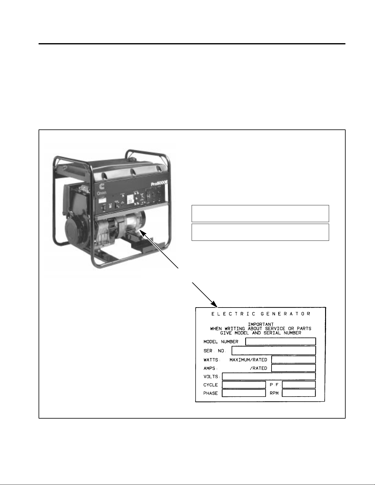
MODEL IDENTIFICATION
When contacting an Onan dealer for parts or ser-
vice, provide the model and serial numbers from the
genset nameplate (Figure 1). Write the model and
serial numbers in the boxes provided in Figure 1 to
make them easy to find.
MODEL NUMBER:
SERIAL NUMBER:
SET NAMEPLATE LOCATED ON
OPPOSITE SIDE OF GENERATOR
SERIAL NUMBER PLATE
FIGURE 1. GENSET IDENTIFICATION
2
Page 5
RECOIL
Redistribution or publication of this document,
by any means, is strictly prohibited.
STARTER
ELECTRIC STARTER
LOCATION (OPTIONAL)
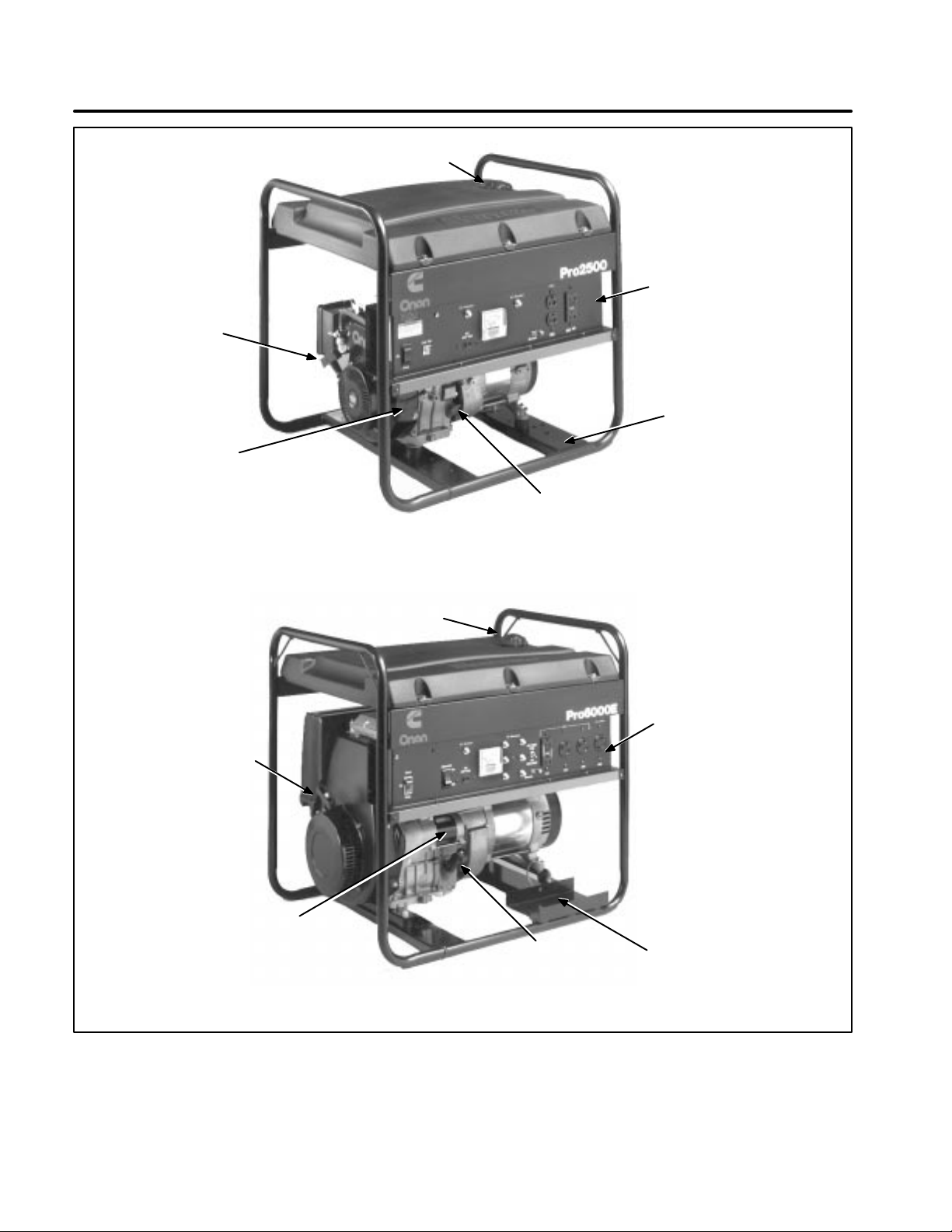
2.0 KW, 2.5 KW, 3.5 KW, 4.0 KW GENERATOR SETS
FUEL FILL
RECEPTACLE/
CONTROL
PANEL
BATTERY TRAY LOCATION
(SETS WITH ELECTRIC START)
OIL FILL &
DIPSTICK
RECOIL
STARTER
ELECTRIC
STARTER
FUEL FILL
OIL FILL &
DIPSTICK
5.0 KW, 6.0 KW GENERATOR SETS
RECEPTACLE/
CONTROL
PANEL
BATTERY
TRAY
FIGURE 2. COMPONENT LOCATIONS
3
Page 6

FUEL RECOMMENDATIONS
Redistribution or publication of this document,
by any means, is strictly prohibited.
Use clean, fresh unleaded gasoline with an octane
rating (anti-knock index) of 87 or higher.
During some times of the year only mandated “oxygenated” gasolines may be available; these are acceptable for use, but not preferable. Using leaded
gasoline will result in the extra maintenance required for removing combustion chamber and
spark plug deposits. Do not use gasoline or gasoline additives (de-icers) containing methanol, which
can be corrosive to fuel system components.
Single-grade SAE 30 oil is better when temperatures are consistently above freezing. Multigrade
oils are better when wide temperature variations
are expected.
STARTING BATTERIES
A set with an electric starter requires a 12 volt starting battery. Prompt starting requires sufficient battery capacity and battery cable size. Neither cranking performance nor starter service life will be adequate with an undersized battery.
CAUTION
Do not use gasoline or gasoline additives containing methanol because methanol
can be corrosive to fuel system components.
Avoid using highly leaded gasolines and lead
additives because of the extra engine maintenance that will be required.
WARNING
Gasoline is highly flammable and
can cause severe personal injury or death. Do
not smoke if you smell gasoline or are near fuel
tanks or gasoline-burning equipment or are in
an area sharing ventilation with such equipment. Keep flames, sparks, pilot lights, electrical arcs and arc-producing equipment and all
other sources of ignition well away.
ENGINE OIL RECOMMENDATIONS
Use premium quality motor oil. Look for the API
(American Petroleum Institute) classification and
use Class SG or SH oil (also SG/CD, SG/CE, SH/
CD or SH/CE). Also look for the SAE (Society of Automotive Engineers) viscosity grade. See the Oil
Change description for the viscosity grade appropriate for the temperatures expected.
See
Maintenance
and any instructions available
from the battery manufacturer for battery maintenance. Note that as long as the set is run regularly ,
the automatic battery recharging system on the engine should maintain battery charge. See OUT -OFSERVICE PROTECTION under
ning the Set
regarding battery care during storage
Starting and Run-
for prolonged periods.
EXHAUST SYSTEM
EXHAUST GAS IS DEADLY! Generator sets must
never be operated inside buildings or other enclosed spaces without ample fresh air ventilation.
Gensets used inside buildings or other enclosed
spaces must be equipped with a leak-free exhaust
system that carries all exhaust gases to the outside,
well away from all windows, doors, vents and other
openings into the building or enclosure.
It is the responsibility of the equipment operator(s)
to check for exhaust leaks on a daily basis and to
have all leaks repaired before continuing to operate
the equipment.
4
Page 7

Starting and Running the Set
Redistribution or publication of this document,
by any means, is strictly prohibited.
EXHAUST GAS IS DEADLY!
Exhaust gases contain carbon monoxide, an odorless and colorless gas. Carbon monoxide is poisonous and can cause unconsciousness and death. Symptoms of carbon monoxide poisoning include:
•
Dizziness
•
Nausea
•
Headache
•
Weakness and Sleepiness
IF YOU OR ANYONE ELSE EXPERIENCE ANY OF THESE SYMPTOMS, GET OUT INTO THE FRESH
AIR IMMEDIATELY. If symptoms persist, seek medical attention. Shut down the engine and do not
operate it until it has been inspected and repaired.
Make certain the exhaust system is properly installed. Inspect it every time the engine is started
and after every eight hours of continuous operation.
•
Throbbing in Temples
•
Muscular Twitching
•
Vomiting
•
Inability to Think Coherently
PRE-START CHECKS
Before the first start of the day and after every eight
hours of operation perform the maintenance listed
in Table 2 (Periodic Maintenance Schedule) of this
manual. Keep a log of maintenance and the hours
run, and perform any maintenance that may be due.
If the set has been in storage, return the engine to
service as instructed in
Operation
TION in this section.
WARNING
under OUT-OF-SERVICE PROTEC-
Moving parts can cause severe per-
Returning The Genset To
sonal injury or death. Hot exhaust parts can
cause severe burns. Stay clear of hot or moving
parts. Make sure all protective shields and
guards are secure in place before starting up
the equipment.
CONTROL PANEL
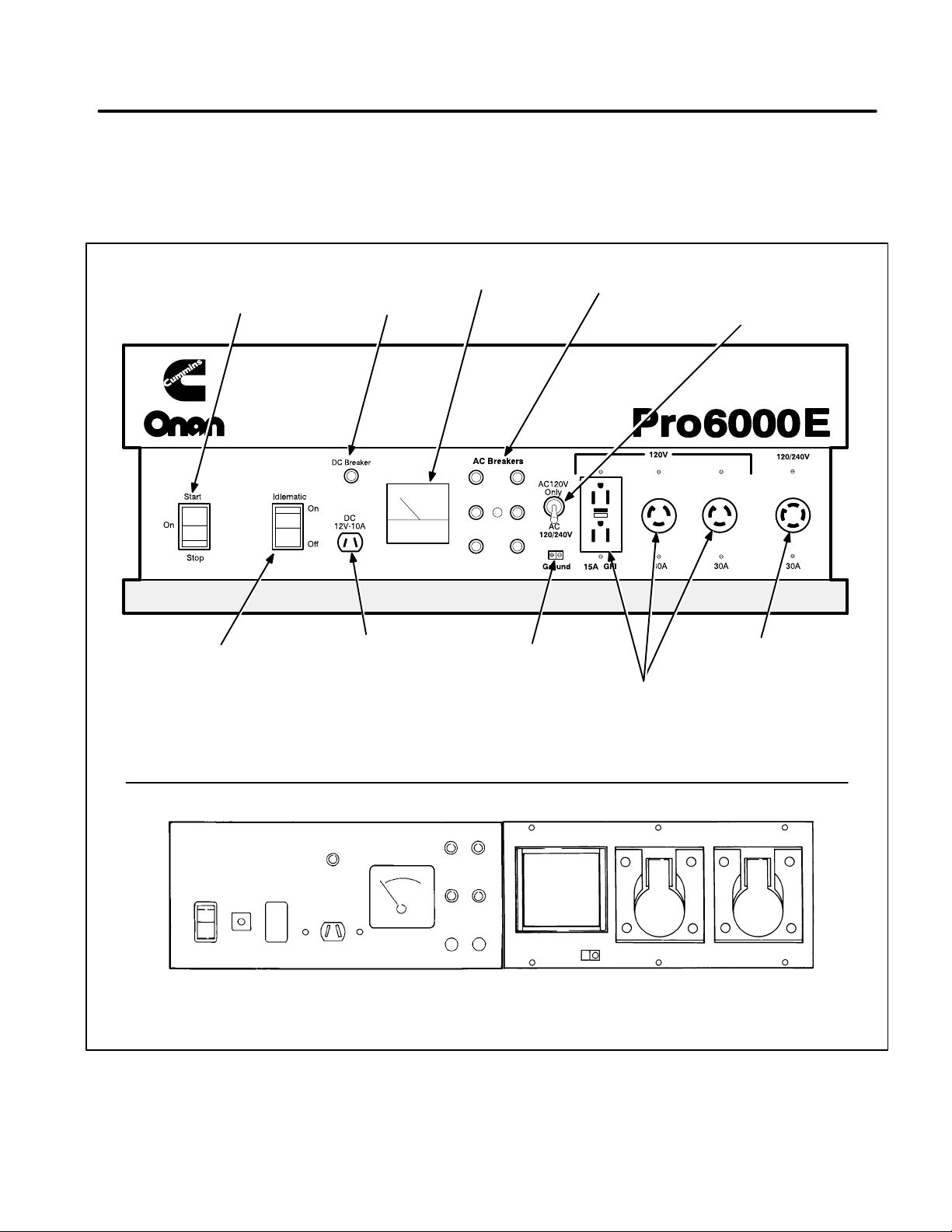
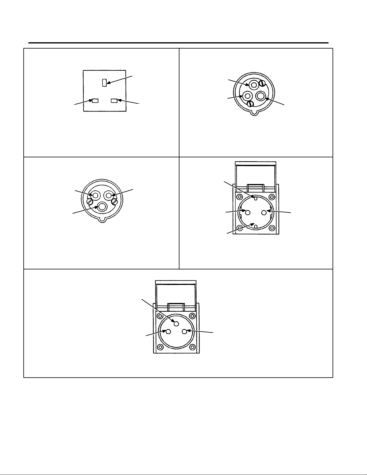
Figure 3 illustrates one of the control panels. Different sets use different receptacle panels: see Figure
4 for illustration of a control panel on a 50 Hz set.
Components
On/Stop Switch (Recoil-only Start Models):
lows the engine to be started and run when the
switch is in the On position. Stops the engine when
held in the Stop position.
Al-
cranking. When engine starts, release the switch
and it will return to the On position. To stop the engine, hold the switch in the Stop position until the
engine stops running.
NOTE: The engine can be recoil started when the
switch is in the On position.
Low Oil Light (4.0 kW and below):
engine oil level. Low Oil Light will flash during
cranking or will flash during operation and the generator set will stop if the engine oil level is below the
low working level.
Voltmeter:
Shows generator AC output voltage.
AC and DC Circuit Breakers:
for the generator from short circuits or overloads.
Full Power Switch:
power operation from the 120 VAC receptacles or
shared power between the 120 VAC and 240 VAC
receptacles. Switch setting also affects voltmeter
readings; refer to voltmeter description.
Allows operator to select full
Idlematic Switch (3.5 kW and above):
engine speed control. In the On position, the engine
operates at idle speed until a load is applied. The
Idlematic automatically increases the engine to full
speed when a load is applied. This feature reduces
engine wear and conserves energy. In the Off position the engine operates at full speed.
Indicates low
Provide protection
Automatic
Start/On/Stop Switch (Electric Start Models):
Pushing switch into the Start position begins engine
Earth Ground Lug T erminal:
set to be grounded to earth ground.
Allows the generator
5
Page 8
Additional Controls
Redistribution or publication of this document,
by any means, is strictly prohibited.
ator set is not in use. See Figure 5.
Fuel Valve:
Controls fuel flow to engine. Setting
fuel valve to Open position allows fuel to flow to engine. Set fuel valve to Closed position when gener-
START/ON/STOP
SWITCH
DC BREAKER
RESET SWITCH
AC VOLTMETER
Choke Lever:
Restricts air flow to the carburetor
for starting a cold engine. See Figure 6 or Figure 7.
AC BREAKER
RESET SWITCHES
FULL POWER
SWITCH
IDLEMATIC
SWITCH
(OPTIONAL)
DC RECEPTACLE (PLUG
WITH JUMPER CLIPS
INCLUDED WITH GENSET)
EARTH
GROUND
LUG
AC RECEPTACLES
(120 VAC)
AC RECEPTACLE
FACEPLATE WITH AC RECEPTACLES (60 HZ GENSETS)
FACEPLATE WITH COVERED AC RECEPTACLES (50 HZ GENSETS)
FIGURE 3. CONTROL PANEL
(120/240 VAC)
ES1961-1
6
Page 9
E
Redistribution or publication of this document,
by any means, is strictly prohibited.
(GROUND
SOCKET)
N
(NETRAL
SOCKET)
N
(120 VAC TO
GROUND)
UK RESIDENTIAL
RECEPTACLE
(GREY − 13 AMP, 220/240V)
N
(120 VAC TO
GROUND)
E
(GROUND
SOCKET)
EUROPEAN INDUSTRIAL RECEPTACLE
(BLUE − 16 AMP, 220/240V)
L
(120 VAC TO
GROUND)
L
(120 VAC TO
GROUND)
L
(120 VAC TO
GROUND)
UK INDUSTRIAL RECEPTACLE
(YELLOW − 16 AMP, 110/130V)
GROUND
CONNECTION
L
(120 VAC TO
GROUND)
GROUND
CONNECTION
GERMAN RESIDENTIAL RECEPTACLE
E
(GROUND
SOCKET)
N
(120 VAC TO
GROUND)
(GREY − 16 AMP, 220V)
E
(GROUND
PIN)
L
(120 VAC TO
GROUND)
FRENCH RESIDENTIAL
RECEPTACLE
(GREY − 16 AMP, 220V)
N
(120 VAC TO
GROUND)
FIGURE 4. RECEPTACLE VARIATIONS, 50 HZ GENERATOR SETS
7
Page 10

STARTING PROCEDURE
Redistribution or publication of this document,
by any means, is strictly prohibited.
After checking the generator set as described in the
Pre-Start Checks and disconnecting all loads from
the generator set, follow each of the steps in sequence.
WARNING
Inhalation of exhaust gas can result
in severe personal injury or death. Do not operate the generator set in poorly ventilated areas
such as indoors, inside tanks, confined areas,
depressions, or any area where exhaust gases
might accumulate. Locate the exhaust outlet so
that exhaust gases will not accumulate during
operation.
WARNING
Due to the danger of severe personal injury or death, do not operate the generator
set in hazardous areas where it might ignite
gases, combustibles, or explosive materials.
WARNING
Generator sets present the hazard
of electrical shock that can result in severe personal injury or death. Never expose the generator set to rain, snow, or similar wet conditions
when operating.
WARNING
The muffler becomes very hot during and after generator set operation and can
cause severe burns. Do not touch hot muffler.
CAUTION
The voltage surge at start-up can
damage appliances (TV sets, microwave ovens,
computers, etc.). Always disconnect all loads
before starting the generator set.
Electric Start Models
1. Open the fuel valve (Figure 5). (4.0 kW sets
and below: Be sure that the speed control lever
is in the high speed (“H” position [Figure 6]).
2. Set the choke lever to the CLOSE position (Figure 6 or Figure 7). If engine is warm from previous operation, do not close the choke.
3. On models equipped with Idlematic switch (3.5
kW and above), position the switch to the OFF
position before starting. Let the engine warm
up for three to five minutes before switching the
Idlematic switch to ON (if desired).
4. Start the engine by pressing the Start/On/Stop
switch to the START position. Release switch
when engine starts and it will return to the On
position. Gradually open the choke lever as
the engine warms up. Let the engine warm up
for three to five minutes before applying load.
The voltmeter on the control panel will indicate
generator output voltage.
If the oil watch lamp (on models so equipped)
flashes during cranking or running, or if the engine starts and shuts off, stop the engine and
check the oil level. Add oil as recommended in
the Maintenance section.
5. Proceed to
Adding Loads
in this section.
Manual Start Models
1. Open the fuel valve: see Figure 5. (4.0 kW sets
and below: Check to be sure that the speed
control lever is in the high speed (”H”) position
[Figure 6]).
2. Set the choke lever to the CLOSE position (Figure 6 or Figure 7). If the engine is warm from
previous operation, do not close the choke.
3. On models equipped with Idlematic switch (3.5
kW and above), position the switch to the OFF
position before starting. Let the engine warm
up for three to five minutes before switching the
Idlematic switch to ON (if desired).
4. Move the engine switch to the On position.
5. With one hand on the generator set to steady it,
grip the recoil handle and pull out smoothly and
quickly. Repeat as necessary. When the engine starts, gradually open the choke lever as
the engine warms up. Allow the engine to
warm up for three to five minutes before applying a load.
If the oil watch lamp (on models so equipped)
flashes during cranking or running, or if the engine starts and shuts off, stop the engine and
check the oil level. Add oil as recommended in
the Maintenance section.
8
Page 11
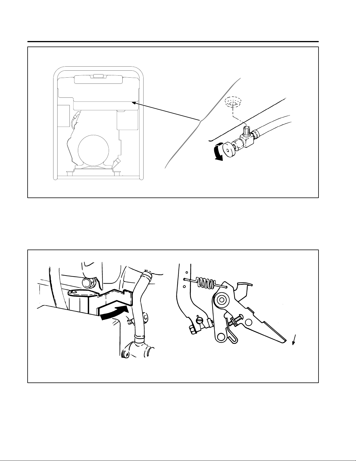
FUEL VALVE LOCATED AT REAR
Redistribution or publication of this document,
by any means, is strictly prohibited.
(SERVICE SIDE) OF GENSET
UNDER LEFT END OF FUEL TANK
OPEN
FIGURE 5. FUEL VALVE (ALL GENSETS)
FS1828-1
M1838
CLOSE (START ENGINE)
CHOKE LEVER
LOW
M1841-1
HIGH
(START ENGINE)
SPEED CONTROL LEVER
FIGURE 6. SPEED CONTROL AND CHOKE OPERATION,
GENSETS 4.0 KW AND BELOW
9
Page 12
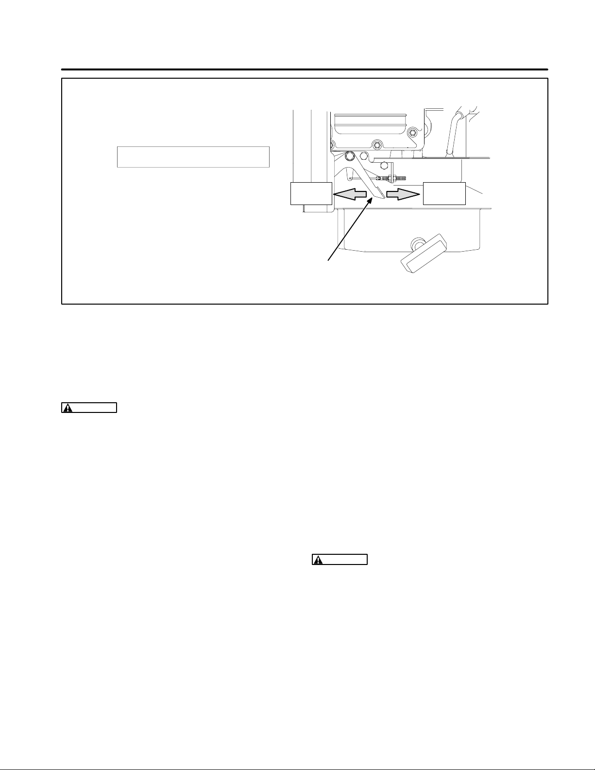
TOP VIEW (FUEL TANK REMOVED
Redistribution or publication of this document,
by any means, is strictly prohibited.
TO SHOW LEVER POSITIONS)
CHOKE
CHOKE LEVER
FIGURE 7. CHOKE OPERATION, 5.0 KW AND 6.0 KW GENSETS
ADDING LOADS
CAUTION
high operating temperatures that could damage
the generator set. Keep the load within the
nameplate rating.
Continuous overloading can cause
Adding AC Loads
1. Note the rated output of the generator set (from
the generator set nameplate or the
section).
tions
2. Check the load rating of each load. Table 1 lists
typical wattages for common appliances and
tools.
3. Add the wattages of the loads and make sure
that the total wattage is not more than the genset rated output. Note the following example.
Specifica-
CHOKE
OPEN
MANUAL
CLOSE
would be necessary to disconnect the 1500
watt heater.
If a motor load and another load have a combined wattage close to the rated output of the
generator set, start the motor load first and
let it run at normal speed before connecting the
other load. Motor loads consume much more
power during start up than they do when they
are running (some motors draw up to three
times their running load).
4. Connect the AC loads to the receptacle(s) on
the control panel. Make sure the cord and plug
connector have ground terminals.
WARNING
Electrical shock can cause severe
personal injury or death. Cord and plug equipment must have a ground terminal to provide
additional protection.
Example:
The 3.5 kW models have a maximum power output of 3500 watts and a rated
output of 3000 watts. A 1500 watt heater, 900
watt circular saw, 500 watt drill and a 100 watt
light could all be operated at the same time. To
operate a second saw rated at 900 watts, it
10
High Altitudes
Maximum power decreases roughly four percent
for each 1000 feet (310 m) above sea level, after the
first 1000 feet) . When operating the generator set
at an altitude above 1000 feet, calculate the altitude
derating to determine maximum AC load capacity.
Page 13

Models with Idlematic:
Redistribution or publication of this document,
by any means, is strictly prohibited.
Move the Idlematic switch
to ON to activate this feature; it controls engine
speed so the set will operate at idle speed with noload and full speed when a load is connected.
Leave the Idlematic Switch OFF if there will be many
small interrupted loads or loads under 0.8 amperes.
TABLE 1. APPROXIMATE POWER USAGE OF
COMMON APPLIANCES
WARNING
Batteries emit a highly explosive
gas that can be ignited by electrical arcing,
smoking, or other ignition source. When charging batteries, connect cables to the battery before connecting cables to the generator set.
This will reduce the risk of arcing at the battery
that could cause an explosion. When battery
charging is complete, remove the cable at the
generator set before removing cables from the
battery. Always remove the negative (-) cable
before the positive (+) cable, and replace it after
the positive cable.
Appliance or Tool Approximate
Running Wattage
Battery Charger Up to 800. . . . . . . . . . . . . . . . .
Bench Grinder (8 in.) 1400. . . . . . . . . . . .
Circular Saw (7-1/4 in.) 900. . . . . . . . . . .
Coffee Maker 850. . . . . . . . . . . . . . . . . . .
Drill (3/8 in.) 400. . . . . . . . . . . . . . . . . . . .
Electric Water Pump 550. . . . . . . . . . . . .
Electric Broom 200-500. . . . . . . . . . . . . . . . . .
Electric Drill 250-750. . . . . . . . . . . . . . . . . . . .
Electric Stove (Per Element) 350-1000. . . . . .
Electric Water Heater 1000-1500. . . . . . . . . . . .
Portable Heater 1500. . . . . . . . . . . . . . . . .
Refrigerator 600-1000. . . . . . . . . . . . . . . . . . . .
Space Heater 1000-1500. . . . . . . . . . . . . . . . . . .
Sump Pump 350. . . . . . . . . . . . . . . . . . . .
Television 200-600. . . . . . . . . . . . . . . . . . . . . .
Trimmer (12-in. heavy duty) 500. . . . . .
See text for starting watts of motor loads.
Adding DC Loads
Connect the DC loads to the DC receptacle on the
control panel. Make sure that polarities are correct
when attaching positive (+) and negative (-) leads.
Refer to the Specification section for maximum DC
output current at 12 volts.
Do not connect AC loads while using DC power on
2.0 kW model.
CIRCUIT BREAKERS
If an AC or DC circuit breaker opens, check to see if
the generator set is overloaded. If so, remove some
of the load from the generator set. Reset the circuit
breaker by pushing in the indicator (reset after waiting a minimum of 10 seconds after tripping).
GROUNDING
Receptacles
Generator set receptacles are internally grounded
to the generator set frame.
Earth Ground Lug Terminal
Ground the generator set to earth ground by connecting a suitable ground wire to the earth ground
lug terminal on the generator set control panel, then
connect the other end of the wire to a suitable earth
ground according to local electrical codes and conditions.
Do not connect grounds from appliance loads to the
Earth Ground Lug terminal. Earth Ground Lug Terminal is for connecting the generator set to earth
ground only.
NOTE: The Idlematic switch must be off when only
DC loads are connected.
NOTE: Do not leave DC load connected to the DC receptacle with the generator set not operating.
LOW OIL SHUTDOWN SYSTEMS
(4.0 kW and below)
The Oil Watch light flashes during cranking if the oil
level is low. It also flashes and stops the generator
set if the set is running and the oil level reaches the
11
Page 14
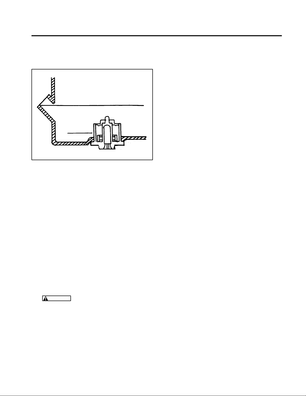
low working level of the Oil Watch. See Figure 8.
Redistribution or publication of this document,
by any means, is strictly prohibited.
Add oil as recommended in the
Maintenance
sec-
tion before attempting to restart.
UPPER OIL LIMIT
OIL WATCH
WORKING
LEVEL
LS1149
OPERATING RECOMMENDATIONS
High/Low Operating Temperatures
High Operating Temperatures:
1. See that nothing obstructs the airflow to and
from the generator set.
2. Keep the engine cooling fins clean. Air housings should be properly installed and maintained.
3. Use the proper viscosity oil as recommended
in the oil change description.
Low Operating Temperatures:
1. Use fresh gasoline and keep the tank filled to
avoid condensation.
2. Keep the spark plug clean and correctly
gapped.
3. Use the proper viscosity oil as recommended
in the oil change description.
FIGURE 8. TYPICAL OIL WATCH
(GENSETS 4.0 KW AND BELOW)
(5.0 kW and above)
These gensets are equipped with pressure-lubricated engines that will automatically stop if low oil
pressure is sensed. A short time delay allows the
engine to be started after an oil change. If the engine stops during running, or starts but then stops,
check the oil level and add oil if needed, as described in the Maintenance section of this manual.
STOPPING
1. Remove all loads from the generator set.
2. Let the generator set run for three to five minutes to allow the engine to cool down.
3. Close the fuel valve.
WARNING
of fire or explosion that can result in severe
personal injury or death. Always close the
fuel valve when the engine is not in use to
reduce the risk of fuel leakage.
Gasoline presents the hazard
Extremely Dusty or Dirty Conditions
Observe the following procedures when operating
the generator set in extremely dusty or dirty conditions.
1. Keep the generator set clean and do not allow
dust and dirt to accumulate.
2. Clean the air cleaner more often than shown in
the maintenance schedule.
3. Keep oil and gas in dust-tight containers suitable for storage of fuels.
Generator Set Exercise
Infrequent operation of the generator set can result
in moisture condensation in the engine and difficult
starting. Moisture accumulates because the engine does not run often enough to reach normal operating temperature. This moisture can cause
damage to the engine.
To prevent moisture damage, run the generator set
at 50 percent capacity electrical load (see
cations
section) two hours every four weeks. A long
Specifi-
exercise period is more effective than several short
periods.
ENGINE BREAK-IN
4. Stop the generator set by pressing and holding
the Start/On/Stop or On/Stop switch in the OFF
position, until the generator set comes to a
complete stop.
12
Correct engine break-in provides the ideal fitting of
all internal moving metal parts, which is essential for
top engine performance. For controlled engine
break-in:
Page 15

1. Operate the equipment as it is intended to be
Redistribution or publication of this document,
by any means, is strictly prohibited.
operated. However, for the first 1-1/2 hours, if
possible, operate the equipment at half the
available engine power, occasionally operating
at full power for brief periods. Avoid prolonged
low-speed, low-power operation during breakin.
2. Proper engine oil is especially critical during
break-in because of the higher engine temperatures that can be expected. See RECOMMENDED ENGINE OIL in
Introduction
Change the oil if it is not right for the temperatures during the break-in period. See Table 3.
3. Check the oil level twice a day or after every 4
hours of operation during the first 24 hours of
operation.
4. Change the oil and oil filter (5.0 kW, 6.0 kW gensets) after the first 24 hours of operation and
have the valves readjusted by a qualified technician.
OUT-OF-SERVICE PROTECTION
one tablespoon (about 30 ml) of clean engine
oil into the spark plug hole. Turn the engine
over for several revolutions. Replace the
spark plug. Pull the recoil starter handle out
slowly until compression is felt.
4. Drain the oil base while still warm. Refill the
crankcase and attach a tag indicating viscosity of oil used.
WARNING
.
if spilled or splashed on skin. Keep fingers
and hands clear when removing oil drain
Hot oil can cause severe burns
plug, and wear protective clothing.
5.
Electric start models only:
Disconnect the
cables from the starting battery negative (-)
cable first to reduce the risk of arcing. Store
battery in a cool dry place and connect to a
charger every 30 days to maintain full charge.
WARNING
Battery electrolyte can cause
severe eye damage and burns to the skin.
Wear goggles, rubber gloves, and a protective apron when working with batteries.
If you are unable to exercise the generator set regularly , and the set will not be in use for more than
120 days, the following procedure is recommended. Failure to provide out-of-service protection can result in difficult starting, rough engine operation and reduced engine life.
Preparing Generator Set For Storage
1. Add a fuel preservative and stabilizer, such as
OnaFresh, to the fuel supply. Follow manufacturer’s instructions for using the fuel additive.
Run the generator at 50 percent load (see
Specifications
WARNING
of personal injury. Read and follow
manufacturer’s instructions.
2. Disconnect the load. Turn the fuel supply
valve of f and remove the air filter. As the generator set runs out of fuel, squirt fogger, such
as OnaGard
reassemble the air filter.
OnaGard is a trademarks of Onan Corporation.
3. When the generator set runs out of fuel and
stops running, remove the spark plug. Squirt
section) for 30 minutes.
Fuel additives can cause a risk
TM
, into the carburetor intake, then
WARNING
Batteries present the hazard of
explosion, which can result in severe personal injury. Do not smoke or allow any
spark, flame, pilot light, arc-producing
equipment or other ignition sources
around the battery area.
6. Cover the generator set and store in a dry protected area.
Returning the Generator Set to Operation
1. Perform an inspection of the generator set.
2. Check tag on set to verify that oil viscosity is still
correct for existing ambient temperature.
3.
Electric start models only:
battery. Measure specific gravity (1.260 at
80°F [27°C]) and verify level to be at split ring.
If specific gravity is low, charge until correct
value is obtained. If level is low add distilled water and charge until specific gravity is correct.
DO NOT OVERCHARGE.
WARNING
Battery electrolyte can cause
severe eye damage and burns to the skin.
Wear goggles, rubber gloves, and a protective apron when working with batteries.
Clean and check
13
Page 16

WARNING
Redistribution or publication of this document,
by any means, is strictly prohibited.
Batteries present the hazard of
explosion, which can result in severe personal injury. Do not smoke or allow any
spark, flame, pilot light, arc-producing
equipment or other ignition sources
around the battery area.
4. Check the condition of the air filter and check
the engine oil level.
5. Open the fuel supply valve.
6. Start the generator set. Initial start-up may be
slow due to oil in the cylinder. Smoke and
rough operation will occur until the oil in the cylinder is exhausted. If the engine does not start,
check the spark plug.
7. Apply 50 percent load to the generator set until
it runs smoothly. Run the generator set for an
hour.
8. Remove the load and let the generator set run
for three to five minutes to cool down. The generator set is now ready for operation.
14
Page 17
Maintenance
Redistribution or publication of this document,
by any means, is strictly prohibited.
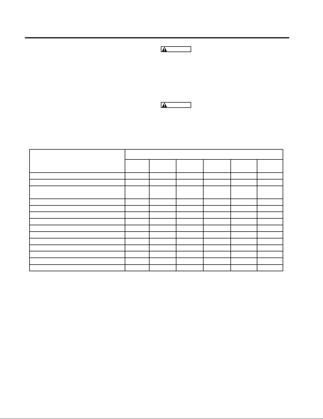
Periodic maintenance is essential for top performance. Use Table 2 as a guide. Under hot or dusty
operating conditions some maintenance operations should be performed more frequently, as indicated by the footnotes in the table.
WARNING
Accidental starting of the generator
set during maintenance can cause severe personal injury or death. Before performing maintenance, disconnect the spark plug wire from
the spark plug. Electric start models: disconnect both generator set starting battery cables.
Keep a log of maintenance performed and the
hours run. Recording maintenance will help you
keep it regular and provide a basis for supporting
warranty claims.
Remove the negative (-) cable first to reduce the
risk of arcing.
WARNING
A hot generator set can cause severe burns. Always allow the generator set to
cool before performing any maintenance or service.
TABLE 2. PERIODIC MAINTENANCE SCHEDULE
SERVICE INTERVAL
SERVICE THESE ITEMS 8 50 EVERY 100 200 400
HOURS HOURS MONTH HOURS HOURS HOURS
General Inspection x
Check Oil Level x
Change Engine Oil and Filter x
(if so equipped)
Clean Air Cleaner Foam Wrapper x
Clean Cylinder Cooling Fins x
Check Starting Battery (if equipped) x
Clean Spark Plug x
Clean and Inspect Muffler x
Replace Fuel Filter x
Inspect, Clean and Regap Spark Plug x
Replace Spark Plug x
Clean Carburetor and Fuel Tank x
Adjust Valve Lash Clearance x
Replace Air Cleaner Element x
1
2,3,4
3
3
5
6
2, 6
3
6
6
1 - Check for loose parts and for oil and fuel leaks. Check exhaust system audibly and visually with the generator set running.
Repair any leaks immediately. Replace corroded exhaust and fuel line components before leaks occur.
2 - Perform after first 24 hours of operation on new sets.
3 - Perform more often in extremely dusty conditions.
4 - Perform more often when operating in hot conditions.
5 - See instructions for battery care provided by the equipment or battery manufacturer.
6 - Must be performed by a qualified mechanic (equipment or Onan dealer).
15
Page 18
DAILY (8 HOUR) MAINTENANCE
Redistribution or publication of this document,
by any means, is strictly prohibited.
The operator should check the following before the
first start of the day and after every eight hours of
operation:
1. Inspect fuel lines and fittings for leaks. Repair
leaks immediately.
2. Look and listen for exhaust system leaks while
the engine is running. Look for cracks and severe rusting in the muffler and tailpipe. Have all
leaks repaired before continuing to operate the
equipment.
WARNING
severe burns. Allow the engine time to cool
before servicing the exhaust system.
Hot exhaust parts can cause
DO NOT FILL TO A LEVEL ABOVE THE FULL
MARK ON THE DIPSTICK. Drain the excess
oil if too much has been added.
CAUTION
Too much oil can cause high oil
consumption, high operating temperatures
and oil foaming. Too little oil can cause severe engine damage. Keep the oil level between the Full and Add marks on the dipstick.
Reinstall the dipstick and cap after checking or
adding oil, making sure the cap is properly
seated. On engines with long oil fill tubes, secure the cap by pushing it down and turning it
clockwise.
OIL AND FILTER CHANGE
3. Check the engine for dirt and debris and clean
the flywheel air inlet screen and cylinder cooling fins as necessary.
CAUTION
A clogged flywheel air inlet
screen or dirty cooling fins can cause overheating and engine damage. Keep the cooling fins and air inlet screen clean.
4. Check the engine oil level. The equipment
must be parked on a level surface and the engine stopped. To get an accurate reading, wait
a minute or so to allow the oil to settle in the
crankcase if the engine has been running.
WARNING
Crankcase pressure can blow
hot engine oil out the fill tube causing severe burns. Always stop the engine before
removing the oil fill cap.
(Gensets 4.0 kW and below) Remove the oil
cap and observe the oil level. The oil level
should appear at the top of the oil port.
(Gensets 5.0 kW and above) Pull the dipstick
up to remove it from the fill tube. Wipe the dip
stick clean, push it back into the oil fill tube until
the cap seats and then withdraw it to check the
oil level.
If the oil level is low, add API Class SG or SH oil
(also SG/CD, SG/CE, SH/CD or SH/CE) having an SAE viscosity grade appropriate for the
expected temperatures, as indicated by
Table 3.
NOTE: Sets 4 kW and below do not use oil filters.
WARNING
State and federal agencies have determined that contact with used engine oil can
cause cancer or reproductive toxicity. Do not
contact or ingest. Use rubber gloves and wash
exposed skin.
See Table 2 for scheduled oil change and filter replacement. See Figures 9 and 10 for oil filter and oil
drain locations.
1. Run the engine until it is warm. Stop the engine
and disconnect the spark plug and, if so
equipped, the battery (negative [-] cable).
Make sure the set is level.
WARNING
Accidental starting of the engine can result in severe personal injury or
death. Always disconnect the spark plug
and the battery (negative [-] cable) before
changing oil.
2. Remove the oil fill cap.
WARNING
Crankcase pressure can blow
hot engine oil out the fill opening causing
severe burns. Always stop the genset before removing the oil fill cap.
3. Place a pan under the oil drain opening and remove the oil drain plug. Reinstall the plug securely after the oil has drained completely.
(Gensets 5.0 and above:) Spin off the oil filter
canister, drain the oil and discard the filter according to local regulations.
16
Page 19
Thoroughly wipe off the filter mounting surface.
Redistribution or publication of this document,
by any means, is strictly prohibited.
Make sure the gasket is in place on the filter
canister and apply a thin film of oil to the gasket.
Spin on the new filter canister by hand until the
gasket just touches the mounting pad and then
turn it an additional 1/2 to 3/4 turn. Do not overtighten.
4. Refill with API Class SG or SH oil (also SG/CD,
SG/CE, SH/CD or SH/CE) having an SAE viscosity grade appropriate for the expected temperatures, as indicated by Table 3. See
fications
TABLE 3. OIL VISCOSITY VS. TEMPERATURE
10° F to 100° F (-12° C to 38° C)
0° F to 80° F (-18° C to 27° C)
-20° F to 50° F (-28° C to 10° C) 5W-30
for the oil capacity.
EXPECTED AMBIENT
TEMPERATURES
32° F (0° C) and higher 30
VISCOSITY
Speci-
SAE
GRADE
15W-40
(OnaMax)
10W-30
10W-40
DO NOT FILL TO A LEVEL ABOVE THE FULL
MARK ON THE DIPSTICK. Drain the excess
oil if too much has been added.
CAUTION
Too much oil can cause high oil
consumption, high operating temperatures
and oil foaming. Too little oil can cause severe engine damage. Keep the oil level between the Full and Add marks on the dipstick.
5. Reconnect the spark plug and battery.
6. Start the engine and run it for a short time while
checking for oil leaks around the drain plug and
oil filter . Do not overtighten: tighten only as necessary to eliminate leaks.
7. Used oil is harmful to the environment. Pour
the used oil into a sealed container and deliver
it to the nearest recycling center.
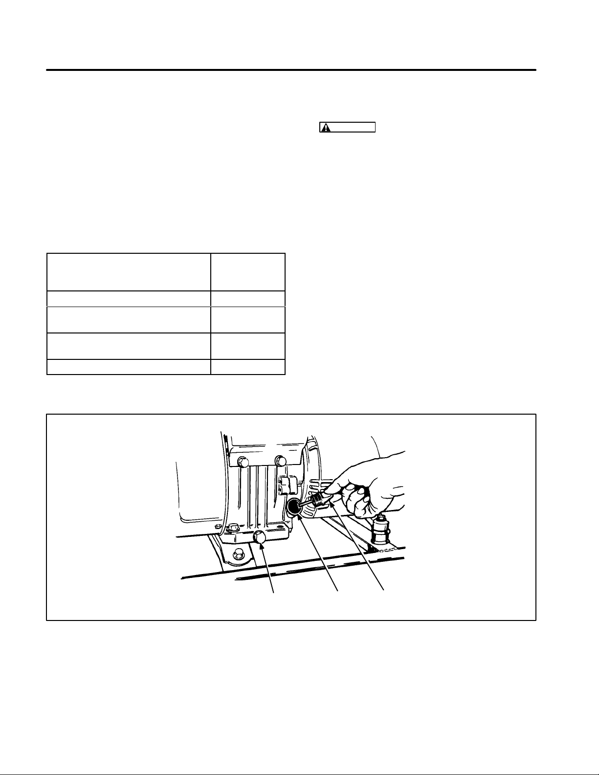
FIGURE 9. OIL CHECK/REFILL, GENSETS 4.0 KW AND BELOW
OIL DRAIN
PLUG
OIL
PORT
LS1122
OIL
CAP
17
Page 20
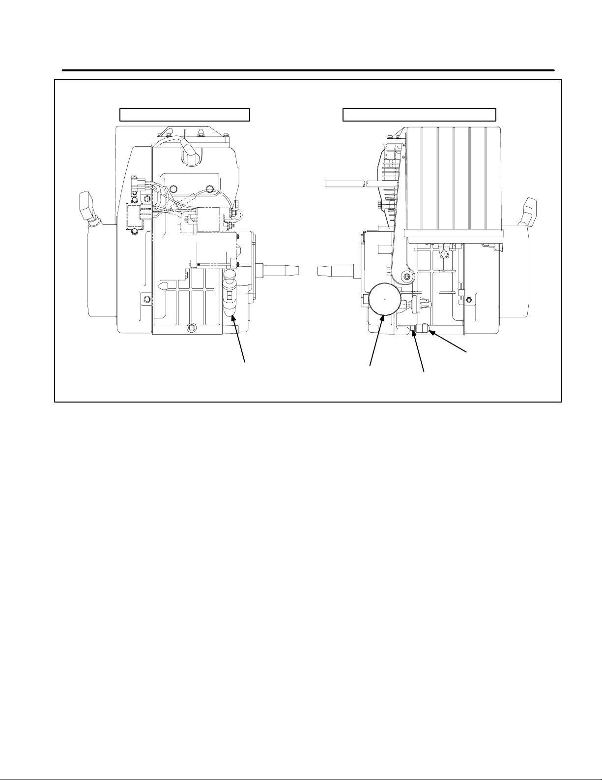
CONTROL SIDE OF ENGINE SERVICE SIDE (REAR) OF ENGINE
Redistribution or publication of this document,
by any means, is strictly prohibited.
90 DEGREE
OIL FILL AND
DIPSTICK
OIL FILTER
OIL DRAIN
ELBOW
FIGURE 10. OIL CHECK/REFILL, FILTER REPLACEMENT, 5.0 KW AND 6.0 KW GENSETS
AIR CLEANER MAINTENANCE
Gensets 4.0 kW And Below
1. Carefully remove the air cleaner cover and the
air cleaner element. See Figure 11.
2. Remove foam wrapper and wash in detergent
and water. Dry foam wrapper thoroughly. Use
low pressure air on the inside of the paper element to remove dust and dirt. Replace paper
element at every sixth cleaning or sooner if
dusty conditions exist or if the paper is torn.
3. Reassemble filter into the housing and carefully install the air cleaner cover.
5.0 And 6.0 kW Gensets
1. Remove the outer cover by rotating the quarter-turn fastener counterclockwise to its vertical position. Then lift the cover and remove it.
See Figure 12.
2.
(Foam wrapper only)
When cleaning the
foam wrapper, do not remove the inner air
cleaner cover. Remove and wash the foam
wrapper in water and detergent. Squeeze the
foam wrapper dry like a sponge. Rinse with
clean water and allow it to dry. Coat the wrapper evenly with one tablespoon (14 grams) of
SAE 30 engine oil. Knead the oil into the wrapper and wring out the excess oil.
Failure to adequately wring out excess oil from
the wrapper may cause a drop in engine power
due to a restriction of inlet air.
3. Re-install the foam wrapper over the paper air
cleaner element by stretching it over the inner
cover. Completely cover all exposed paper
pleats. Replace the foam wrapper when it becomes torn or stretched.
4.
(Air cleaner element replacement)
To keep
debris out of the engine, move the choke lever
to the full-choke position to close the choke
18
Page 21
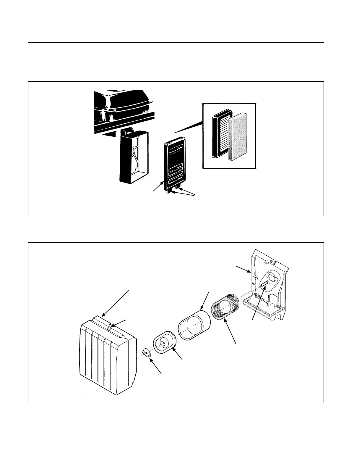
plate. Remove the mounting nut, inner cover
Redistribution or publication of this document,
by any means, is strictly prohibited.
and air cleaner element. Wipe off dust and debris from the air cleaner base.
5. Install the new paper element and secure it
with the inner cover and mounting nut. Tighten
the nut 1-1/2 turns after seating it on the cover.
Reinstall the foam wrapper and outer cover.
PAPER & FOAM
M1845-1
COVER
MOUNTING TABS
(DO NOT TWIST)
FIGURE 11. AIR FILTER REPLACEMENT, GENSETS 4.0 KW AND BELOW
AIR CLEANER
ASSEMBLY BASE
OUTER
COVER
QUARTER−TURN
FASTENER
INNER
COVER
MOUNTING
NUT
FOAM
WRAPPER
SEAL
AIR CLEANER
ELEMENT
FIGURE 12. AIR FILTER REPLACEMENT, 5.0 KW AND 6.0 KW GENSETS
M−2010
19
Page 22
BATTERY CARE
Redistribution or publication of this document,
by any means, is strictly prohibited.
To increase battery life, perform these routine
checks and preventive measures.
WARNING
erator set during maintenance can cause
severe personal injury or death. Disconnect both generator set starting battery
cables before performing maintenance.
Remove the negative (-) cable first to reduce the risk of arcing.
WARNING
gases can cause severe personal injury . Do
not smoke or allow any flame, spark, pilot
light, arc-producing equipment or other
ignition sources near the battery.
WARNING
severe eye damage and skin burns. Wear
goggles, rubber gloves, and a protective
apron when working with batteries.
1. Keep the battery case clean and dry. Wipe battery case with a damp cloth whenever dirt accumulates.
2. Make certain that the battery cable connections are clean and tight. To remove the battery
cables, use a battery puller tool.
3. Identify the cable as positive (+) or negative (-)
before making the connection. Always connect the negative (-) cable last to reduce the
risk of arcing. Apply a light coating of petroleum
jelly or non-conductive grease to battery connections to retard corrosion.
4. Maintain the electrolyte level by adding distilled
water as needed to reach the split-level marker
in the battery. The water component of the
electrolyte evaporates, but the sulfuric acid
component remains. For this reason, only add
water to a low battery.
5. Use a battery hydrometer to check the specific
gravity of the electrolyte in each cell. A battery
Accidental starting of the gen-
Ignition of explosive battery
Battery electrolyte can cause
should be charged if the specific gravity measures less than 1.215. When charging the battery, avoid overcharging. Stop charging battery when the electrolyte specific gravity reaches 1.260, at approximately 80°F (27°C).
FUEL FILTER REPLACEMENT
WARNING
explosion that can cause severe personal injury
or death. Do not permit any flame, spark, pilot
light, cigarette, arcing switch or equipment, or
other ignition source near the fuel system. Inspect for fuel leaks any time service is performed on the fuel system. Keep a fire extinguisher rated ABC near work area.
Clean or replace the fuel filter at the interval recommended in the Maintenance Schedule or if performance problems occur and bad fuel is suspected.
Fuel presents the hazard of fire or
Gensets 4.0 kW And Below
1. Turn the fuel supply valve to the closed position
and allow the set to operate until it runs out of
fuel. Let the generator set cool down before
proceeding.
2. Remove the fuel line from the fuel shutoff valve
and collect the fuel in a suitable container.
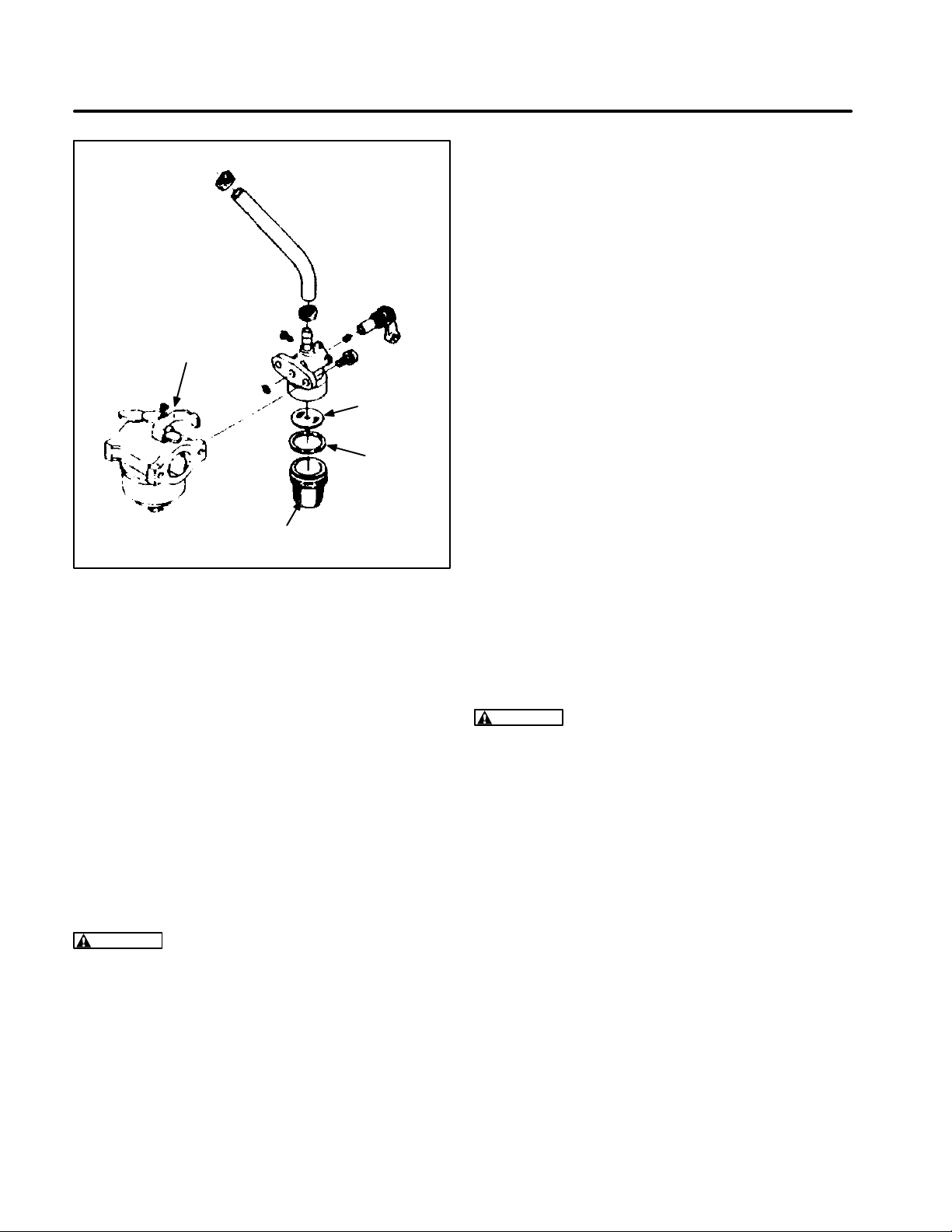
3. See Figure 13. Unscrew the sediment bowl
from the fuel supply valve and clean it.
4. Remove the screen and clean any dirt and particulate off the screen.
5. Reinstall the screen and sediment bowl. Attach the fuel line securely to the fuel shutoff
valve.
5.0 And 6.0 kW Gensets
These sets have a fuel filter screen mounted inside
the gas tank at the fuel shutoff elbow. The screen
should be replaced when performance problems
occur or bad fuel is suspected. Have an Onan Service Center perform this maintenance.
20
Page 23
CARBURETOR
Redistribution or publication of this document,
by any means, is strictly prohibited.
FILTER
ELEMENT
GASKET
CUP
FIGURE 13. FUEL FILTER REPLACEMENT,
GENSETS 4.0 KW AND BELOW
SPARK PLUG MAINTENANCE AND
REPLACEMENT
1. Let the generator set cool down before servicing. Check fuel level in the fuel tank and reduce
the level if tank is full to avoid spilling. Use a
pump designed for use with fuels to lower fuel
tank level and store fuel in a clean container designed for fuel storage.
2. Close the fuel shutoff valve on the bottom of the
fuel tank (Figure 5).
3. Remove the fuel tank mounting nuts and raise
the control panel side of the fuel tank high
enough to access the spark plug. Support the
fuel tank to prevent tilting or dropping.
• Black deposits indicate a rich mixture.
• A wet plug indicates misfiring.
• Badly or frequently fouled plug indicates
the need for a major tune-up.
Refer to Table 2 for scheduled spark plug inspection
and replacement and to
Specifications
for gap size.
To prevent crossthreading the spark plug always
thread it in b y hand until it seats. If the spark plug is
being reused, turn it with a wrench an additional 1/4
turn. If the spark plug is new, turn it an additional 3/8
to 1/2 turn. If you have a torque wrench, tighten the
spark plug to 20 lbs-ft (26 N
•m).
MUFFLER SERVICE
A spark plug with heavy combustion deposits can
cause the generator set to misfire, operate erratically, or stop running when a load is applied. Remove the spark plug and clean carbon and other d e posits off with a wire brush, then inspect and measure plug gap. Plug gap measurements are listed in
the
Specifications
section. If a plug is discolored or
badly fouled, replace it.
If necessary, the fuel tank can be raised for easier
service access as follows:
WARNING
Fuel presents the hazard of fire or
explosion that can cause severe personal injury
or death. Shut fuel valve and handle fuel tank
carefully to prevent fuel leakage. Reduce fuel
level in fuel tank to reduce the risk of spilling
fuel. Do not permit any flame, spark, pilot light,
cigarette, arcing switch or equipment, or other
ignition source near the fuel system. Keep an
ABC type fire extinguisher nearby.
WARNING
A hot muffler can cause severe
burns. Allow the generator set to cool before
servicing the the muffler.
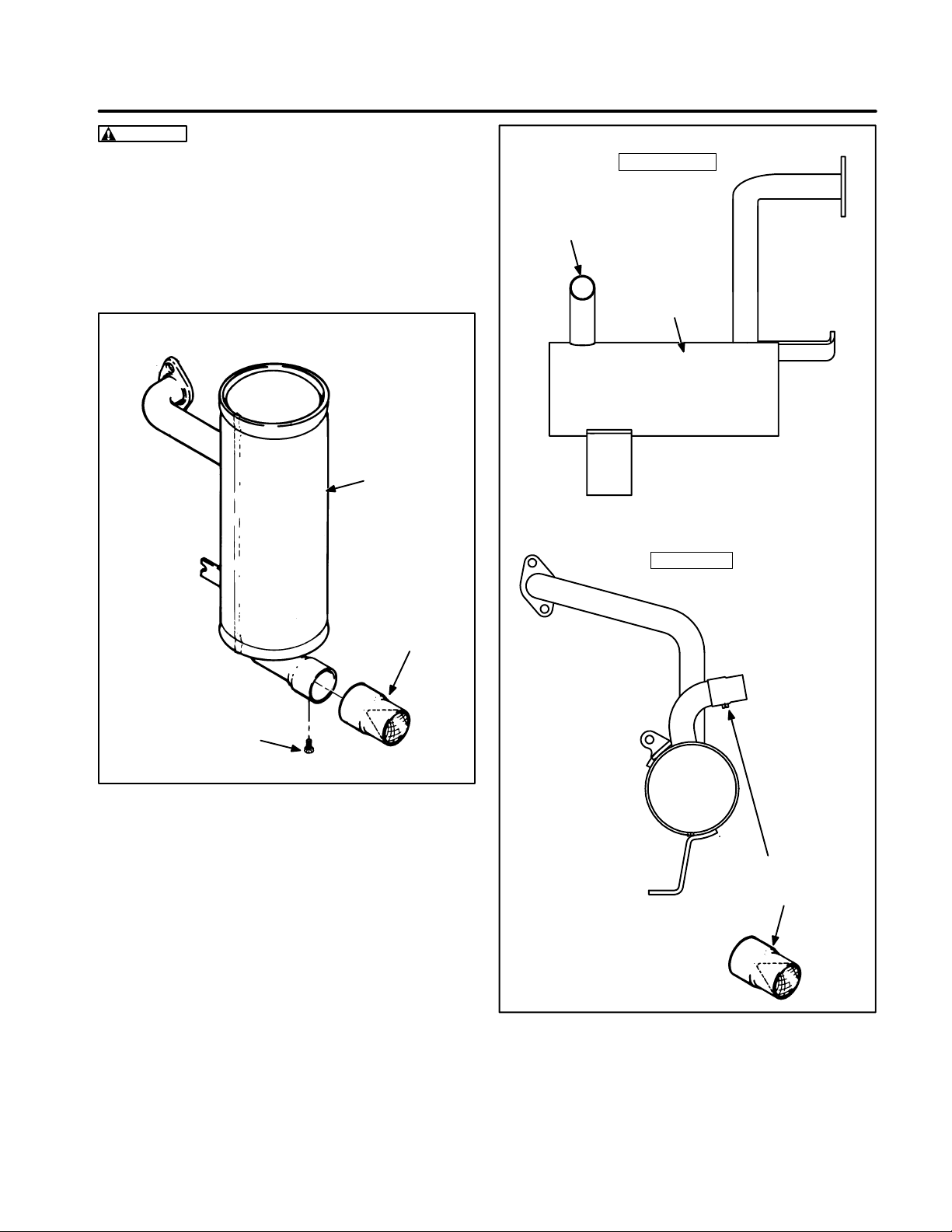
Inspect the muffler for corrosion and physical defects. Operate and generator set and check for exhaust leaks and noisy operation. Replace a noisy or
defective muffler before using the generator set.
The exhaust spark arrester requires periodic cleaning for safe operation and to maintain maximum ef ficiency. Consult the maintenance schedule for recommended cleaning intervals. Allow the generator
set to cool down before servicing the muffler.
Remove the spark arrester screen (Figure 15), inspect for damage, and replace if defective. To
clean, lightly tap the screen and clean any deposits
with a wire brush. Also use a commercial solvent if
necessary. Allow screen to dry, then reassemble
and attach securely.
21
Page 24
WARNING
Redistribution or publication of this document,
by any means, is strictly prohibited.
Most part cleaning solvents are
flammable and misuse can result in severe personal injury or death. Follow the manufacturer’s recommendations. Work in a well ventilated area and do not allow any spark, flame, pilot light, cigarette, or other ignition source near
the generator set. Keep a fire extinguisher rated
ABC near work area.
MUFFLER
FRONT VIEW
TAILPIPE
MUFFLER
SIDE VIEW
ARRESTER
EXS1152-2
MOUNTING
SCREW
FIGURE 14. SPARK ARRESTER CLEANING
(GENSETS 4.0 KW AND BELOW)
SPARK
LOOSEN MOUNTING
SCREW TO REMOVE
SPARK ARRESTER
FIGURE 15. SPARK ARRESTER CLEANING
(5.0 AND 6.0 KW GENSETS)
22
Page 25

CLEANING THE GENERATOR SET
Redistribution or publication of this document,
by any means, is strictly prohibited.
Remove spilled oil and fuel from the generator set
immediately with a dry rag. Dispose of cleaning rag
properly . D o not allow dirt to accumulate on the en-
gine cooling fins or on the control components and
electrical connections. A damp cloth can be used to
clean dust and dirt from the generator set. Cleaning
solvents should not be used, because they can
damage electrical connectors and components.
23
Page 26
Troubleshooting
Redistribution or publication of this document,
by any means, is strictly prohibited.
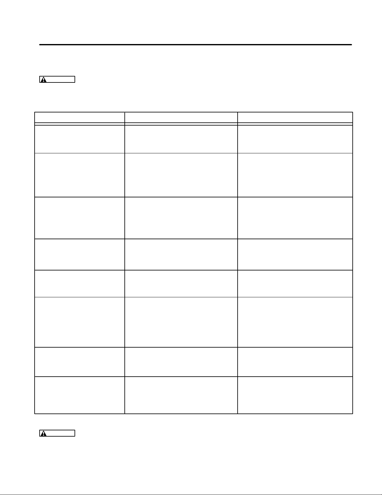
The following troubleshooting guide can be used for basic problem diagnosis. If these recommendations
do not resolve the problem, contact an authorized Onan service center.
WARNING
Many troubleshooting procedures present hazards which can result in severe personal injury or death. Only qualified service personnel with knowledge of fuels, electricity, and machinery hazards should perform service procedures. Review safety precautions on inside cover
page.
Problem Probable Cause
FAILS TO CRANK 1. Low battery. 1. Check battery electrolyte level.
(ELECTRIC START MODELS) 2. Bad battery connection. 2. Clean and tighten all battery
and cable connections.
CRANKS SLOWLY 1. Low battery. 1. Check battery electrolyte level.
(ELECTRIC START MODELS) 2. Bad battery connection. 2. Clean and tighten all battery
3. Oil is too heavy. and cable connections.
4. Load is connected. 3. Replace with recommended oil.
4. Disconnect load while starting.
ENGINE WON’T START 1. Fuel below genset pickup 1. Add fuel.
level in tank. 2. Fully open fuel supply valve.
2. Fuel supply shutoff valve closed. 3. Remove spark plug and clean.
3. Carbon deposits on spark plug. 4. Add oil if necessary.
4. Low oil level.
EXHAUSTING 1. Choke stuck. 1. Open choke
BLACK SMOKE 2. Dirty air filter. 2. Clean or replace air filter.
3. Rich fuel mixture. 3. Contact an Onan service center.
Solution
UNIT RUNS THEN STOPS 1. Out of fuel. 1. Add fuel.
2. Low oil level. 2. Add oil.
3. Excess oil. 3. Reduce engine oil level.
UNIT RUNS THEN SURGES 1. Loose or worn spark plug lead 1. Check spark plug lead connection.
2. Faulty spark plug. 2. Remove and clean or replace.
3. Dirty fuel filter or generator set 3. Check fuel filter and angle of
at too steep of an angle. generator set.
4. Governor out of adjustment 4. Contact an Onan service center.
or lean fuel mixture.
NO AC OUTPUT VOLTAGE 1. Open AC circuit breaker 1. Remove all loads, reset breaker,
due to an overload. check loads for defects. Do not
exceed rated load specifications.
NO DC OUTPUT VOLTAGE 1. Open DC circuit breaker 1. Remove all loads, reset breaker,
due to an overload. check for shorted battery or load
defects. Do not exceed rated
load specifications.
WARNING
A hot generator set can cause severe burns. Always allow the generator set to cool
before performing any maintenance or service.
24
Page 27
Specifications
Redistribution or publication of this document,
by any means, is strictly prohibited.
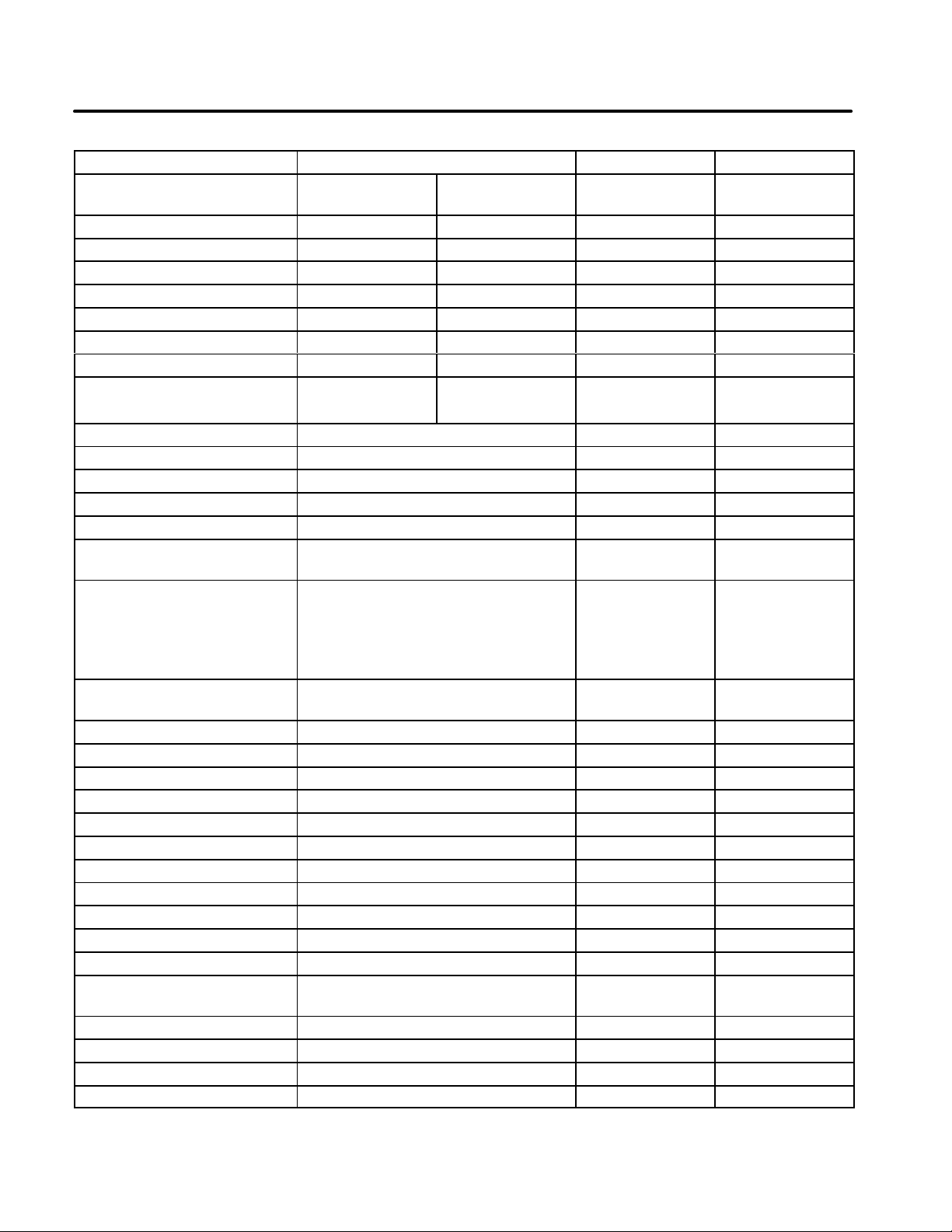
60 HZ GENSETS 2.5 EGHAA 4.0 EGHAB 4.0 EGHEB
Non-CSA
Certified
GENERATOR DETAILS
AC OUTPUT:
Frequency (Hertz) 60 60 60 60
Voltage 120 120 120/240 120/240
Wattage (Max. Power) 1800 2500 4000 4000
Wattage (Rated Power) 1800 2000 3500 3500
Current (Rated Amps) 15 16.7 29.2/14.6 W 29.2/14.6
DC OUTPUT: 12 VDC/120 W 12 VDC/120 W 12 VDC/120 W 12 VDC/120 W
(10 A) (10 A) (10 A) (10 A)
ENGINE DETAILS
Engine Type GH170 GH280 GH280
Engine Speed (RPM) 3600 3600 3600
Fuel Gasoline Gasoline Gasoline
Engine Oil Capacity 0.63 qt (0.6 L) 0.95 qt (0.9 L) 0.95 qt (0.9 L)
Spark Plug Gap 0.028 in.
(0.7 mm)
Engine Valve Lash Intake and
Exhaust:
0.002 - 0.0039 in.
(0.05 - 0.10 mm)
Ignition Timing (BTDC)
(fixed)
Starting System Recoil Recoil Electric/Recoil
Horsepower 5.5 bhp max 9.0 bhp max 9.0 bhp max
Displacement (cc) 169 274 274
21° 25° 25°
0.028 in.
(0.7 mm)
Intake and
Exhaust:
0.002 - 0.0039
in.
(0.05 - 0.10 mm)
0.028 in.
(0.7 mm)
Intake and
Exhaust:
0.002 - 0.0039
in.
(0.05 - 0.10 mm)
GENERATOR DETAILS
Dry Weight 110 lb (50 kg) 145 lb (66 kg) 155 lb ( 70 kg)
Dimensions:
Length - Inches 26.8 (681) 26.8 (681) 26.8 (681)
Width - Inches 22 (559) 22 (559) 22 (559)
Height - Inches 24.6 (625) 24.6 (625) 24.6 (625)
Fuel Tank Capacity 6.5 gal (24.6 L) 6.5 gal (24.6 L) 6.5 gal (24.6 L)
Rated Output Operating
Hrs.
Battery Requirements:
Battery (Group U1) - - 12 Volt
Cold Cranking Amps - - 235
(at 32° F [0° C])
20 13 13
25
Page 28

60 HZ GENSETS 5.0 EGHAB 5.0 EGHEB 6.0 EGHEB
Redistribution or publication of this document,
by any means, is strictly prohibited.
GENERATOR DETAILS
AC Output:
Frequency (Hertz) 60 60 60
Voltage 120/240 120/240 120/240
Wattage (Max. Power) 5000 5000 6000
Wattage (Rated Power) 5000 5000 5500
Current (Rated Amperes) 41.6/20.8 41.6/20.8 45.8/22.9
DC Output: 12 VDC/120 W 12 VDC/120 W 12 VDC/120 W
(10 A) (10 A) (10 A)
ENGINE DETAILS
Engine Type Elite E140H Elite E140H Elite E140H
Engine Speed (RPM) 3600 3600 3600
Fuel Gasoline Gasoline Gasoline
Engine Oil Capacity 1.0 qt (0.95 L) 1.0 qt (0.95 L) 1.0 qt (0.95 L)
Spark Plug Gap 0.035 in. (0.89 mm) 0.035 in. (0.89 mm) 0.035 in. (0.89 mm)
Engine Valve Lash Intake and Exhaust: Intake and Exhaust: Intake and Exhaust:
.006 - .010 in. .006 - .010 in. .006 - .010 in.
(0.15 - 0.25 mm) (0.15 - 0.25 mm) (0.15 - 0.25 mm)
Ignition Timing (BTDC) (fixed) 23° 23° 23°
Starting System Recoil Electric/Recoil Electric/Recoil
Horsepower 14 bhp max 14 bhp max 14 bhp max
Displacement (cc) 390 390 390
GENERATOR SET DETAILS
Dry Weight 175 lb (79 kg) 185 lb (84 kg) 205 lb (94 kg)
Dimensions:
Length - Inches 29.2 (742) 29.2 (742) 29.2 (742)
Width - Inches 22.5 (572) 22.5 (572) 22.5 (572)
Height - Inches 28.3 (719) 28.3 (719) 28.3 (719)
Fuel Tank Capacity 8 gal (30.3 L) 8 gal (30.3 L) 8 gal (30.3 L)
Rated Output Operating Hours 10 10 9
Battery Requirements:
Battery (Group U1) - 12 volt 12 volt
Cold Cranking Amps - 235 235
(at 32° F[0° C])
26
Page 29

50 HZ GENSETS 2.0 EGHAM 3.5 EGHEM 5.0 EGHEM
Redistribution or publication of this document,
by any means, is strictly prohibited.
GENERATOR DETAILS
AC Output:
Frequency (Hertz) 50 50 50
Voltage 110/220 110/220 110/220
Wattage (Max. Power) 2000 3500 5000
Wattage (Rated Power) 1800 3000 4500
Current (Rated Amperes) 16.4/8.2 27.2/13.6 40.9/20.4
DC Output: 12 VDC/100 W 12 VDC/100 W 12 VDC/100 W
(8.3 A) (8.3 A) (8.3 A)
ENGINE DETAILS
Engine Type GH170 GH280 Elite E140H
Engine Speed (RPM) 3000 3000 3000
Fuel Gasoline Gasoline Gasoline
Engine Oil Capacity 0.63 qt (0.6 L) 0.95 qt (0.9 L) 1.0 qt (0.95 L)
Spark Plug Gap 0.028 in. (0.7 mm) 0.028 in. (0.7 mm) 0.035 in. (0.89 mm)
Engine Valve Lash Intake and Exhaust: Intake and Exhaust: Intake and Exhaust:
0.002 - 0.0039 in. 0.002 - 0.0039 in. .006 - .010 in.
(0.05 - 0.10 mm) (0.05 - 0.10 mm) (0.15 - 0.25 mm)
Ignition Timing (BTDC) (fixed) 21° 25° 23°
Starting System Recoil Electric/Recoil Electric/Recoil
Horsepower 5.5 bhp max 9.0 bhp max 14 bhp max
Displacement (cc) 169 274 390
GENERATOR SET DETAILS
Dry Weight 119 lb (54 kg) 165 lb (75 kg) 207 lb (94 kg)
Dimensions:
Length - Inches 26.8 (681) 26.8 (681) 29.2 (742)
Width - Inches 22 (559) 22 (559) 22.5 (572)
Height - Inches 24.6 (625) 24.6 (625) 28 (719)
Fuel Tank Capacity 6.5 gal (24.6 L) 6.5 gal (24.6 L) 8.0 gal (30.3 L)
Rated Output Operating Hours 20.5 13.5 10.5
Battery Requirements:
Battery (Group U1) - 12 volt 12 Volt
Cold Cranking Amps - 235 235
(at 32° F[0° C])
27
Page 30

Important Information for California Users
Redistribution or publication of this document,
by any means, is strictly prohibited.
The Pro series Portable Gensets meets the requirements of California’s Exhaust Emissions Standards
for 1995 and later for Utility and Lawn and Garden
Equipment Engines.
As a California user of this engine, please be aware
that unauthorized modifications or replacement of
fuel, exhaust, air intake, or speed control system
components that affect engine emissions are prohibited. Unauthorized modification, removal or replacement of the engine label is prohibited.
EMISSIONS CONTROL INFORMATION
The California emissions control warranty statement is located
Engine Warranty Information
Engine Valve Lash See
Engine Ignition Timing See
Engine Fuel Requirements
in the same packet of information as this manual when the engine is shipped from the factory.
Specifications.
Specifications.
The engine is certified to operate on unleaded gasoline. See
Fuel Recommendations in
You should carefully review Operator’s and other
manuals and information you receive with your genset. If you are unsure that the installation, use,
maintenance or service of your genset is authorized, you should seek assistance from an approved Onan engine dealer or an approved dealer
for your equipment.
California engine users may use the information below as an aid in locating information related to the
California Air Resources Board requirements for
emissions control.
Introduction
.
Engine Lubricating Oil Requirements See Engine Oil Recommendations in
Engine Fuel Mixture Settings
Engine Adjustments See
Engine Emission Control System
These engines have precision-manufactured carburetors
which are not adjustable.
Starting and Running the Set
The engine emission control system consists of internal engine
modifications.
.
Introduction
.
28
Page 31

Cummins Power Generation
Redistribution or publication of this document,
by any means, is strictly prohibited.
1400 73rd Avenue N.E.
Minneapolis, MN 55432
763-574-5000
Fax: 763-528-7229
Cummins and Onan are registered trademarks of Cummins Inc.
 Loading...