

Page 1

PlayMaker
Version 2.10
User Guide January 2015
Page 2

Copyright © 2015 by Orad Hi-Tec Systems Ltd. All rights reserved worldwide.
No part of this publication may be reproduced, modified, transmitted, transcribed, stored
in retrieval system, or translated into any human or computer language, in any form or by
any means, electronic, mechanical, magnetic, chemical, manual, or otherwise, without
the express written permission of Orad Hi-Tec Systems (www.orad.tv).
Orad provides this documentation without warranty in any form, either expressed or
implied.
Orad may revise this document at any time without notice.
This document may contain proprietary information and shall be respected as a
proprietary document with permission for review and usage given only to the rightful
owner of the equipment to which this document is associated.
This document was written, designed, produced and published by Orad Hi-Tec Systems.
Trademark Notice: Playmaker, Morpho 3D, 3Designer, 3DPlay, Maestro, Maestro
Controller, Maestro PageEditor, JStation, JServer, ProSet, 3DPlay, DVG 2U, DVP-500,
X-pecto, Morpho 3D are trademarks of Orad Hi-Tec Systems Ltd.
All other brand and product names may be trademarks of their respective companies.
Please send any comments on this manual to [email protected].
If you require technical support services, contact Orad Hi-Tec Systems Ltd. at
[email protected] or by phone:
Servers Hotline: +972 54 574 8048, General support: +972 9 7676862.
January 14, 2015
Page 3

Contents
Introduction .......................................................................7
The PlayMaker Server..........................................................................8
The LCD.........................................................................................9
Technical Specifications - Server .....................................................11
Unit Installation ............................................................................ 15
Maintenance and Service Information...............................................16
Connections..................................................................................16
The PlayMaker Controller ...................................................................17
Touchscreen Display ......................................................................18
T-Bar...........................................................................................18
Jog..............................................................................................18
Programmable LCD Keys ................................................................ 18
Keypads.......................................................................................19
Technical Specifications - Controller .................................................20
Maintenance and Service Information...............................................21
Back Panel - Connections ...............................................................22
Conventions Used in this Manual ......................................................... 23
Basics ...............................................................................25
The Main Screen ............................................................................... 26
Video Settings .............................................................................. 27
Audio Settings ..............................................................................29
Controller Settings.........................................................................30
In/Out .........................................................................................31
Maintenance ................................................................................. 32
Data ............................................................................................33
SmartEvents ....................................................................................34
Groups, Pages, and SmartEvents..................................................... 35
SmartEvent Options....................................................................... 38
Network .......................................................................................... 39
Export .............................................................................................40
Auto Import Settings .....................................................................42
Page 4

Recording.....................................................................................43
Using the Virtual Keyboard .............................................................44
Audio Routing ...............................................................................45
Stripping a Recording.....................................................................46
Go To Timecode ............................................................................47
The CLR Key................................................................................. 47
The MENU Key ..............................................................................48
OSD Data (Superimposed Data)..........................................................48
OSD Data for Live/Replay ............................................................... 48
Shutdown ........................................................................................49
RAID Disk Replacement ..................................................................... 50
License Installation ...........................................................................51
Software Upgrades............................................................................ 51
Working in Studio Mode ..................................................................... 52
Managing Recordings.........................................................................52
Replay...............................................................................53
Replaying Video ................................................................................54
Switching Between Channels...........................................................54
Synchronized and Non-Synchronized Modes ......................................... 55
Output ............................................................................................56
Configuring Your Output................................................................. 56
Working in PGM/PVW Mode.............................................................58
Working in 2 PGM Mode .................................................................58
Setting up Multiple Controllers ............................................................59
Cues..................................................................................61
Marking Cues ................................................................................... 62
Cue Setup........................................................................................62
Cue Sorting...................................................................................... 64
Loading a Cue ..................................................................................64
Clips..................................................................................65
About Clips ......................................................................................66
Creating a Clip..................................................................................67
List of Clips .................................................................................. 71
Loading a Clip ...............................................................................73
Page 5

OSD Data for a Loaded Clip ............................................................74
Changing Clips ..............................................................................75
Playing a Clip ...................................................................................76
Playing All Clips.............................................................................76
Looping Clips ................................................................................77
Protecting a Clip............................................................................78
Clip Setup........................................................................................79
Using the Numeric Keypad..............................................................80
Playlists ............................................................................81
Setting the Active Playlist................................................................... 82
Loading the Current Playlist................................................................84
OSD Data for a Playlist...................................................................84
Adding Clips to the Playlist ................................................................. 85
Adding Clips with SmartEvent to a Playlist ........................................86
Adding Clips to Multiple Playlists ...................................................... 86
Changing Clips Within a Playlist .......................................................... 88
Playing a Playlist ........................................................................... 88
Additional Options ......................................................................... 89
Transition Effects...........................................................................90
Setting Clip Speed......................................................................... 91
Playlist Setup ...................................................................................92
Networking.......................................................................95
Copying Clips from a Remote Server....................................................96
Copying Clips from Local Server to Remote Server ................................97
Copying Clips to a Shared Directory or External Device .......................... 97
System Configuration........................................................99
Configuring the Jog ......................................................................... 100
Configuring the T-Bar ...................................................................... 102
AC-8 Analog Audio Converter ........................................................... 103
Audio Configurations for AC-8 ....................................................... 104
AES-8 Audio Converter .................................................................... 108
Audio Configurations for AES-8 ..................................................... 110
Page 6

Video Configurations.......................................................114
Rendering Clips for PlayMaker ........................................120
Using Premiere Pro CS5-CS6......................................................... 120
Using Avid Media Composer .......................................................... 120
Page 7

1.Introduction
Inthissection:
The PlayMaker Server on page 8
The PlayMaker Controller on page 17
Conventions Used in this Manual on page 23
Page 8
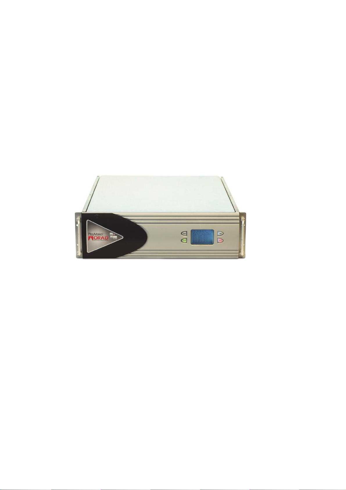
ThePlayMakerServer
PlayMaker is a multi channel, slow motion video server, that provides I-Frame ingest,
synchronized slow motion replay, and editing tools.
PlayMaker currently supports up to eight input/output channels and can be delivered in
a 2, 4, 6, or 8 channel configuration.
The PlayMaker server uses a 3U chassis containing eight video disks, with quick access
to the front panel for disk replacement. The front server panel is equipped with an LCD
screen showing server status, input and genlock detection, disk status, and more. The
server is capable of recording 120 hours in SD (@50 mbps data rate), or 60 hours in
HD (@100 mbps data rate).
To safeguard system integrity, PlayMaker runs on two system disks, using separate
RAID 1 protection, and a dual hot swap power supply. The video storage disks use
RAID 6 dual parity protection.
1.Introduction
Super slow motion: PlayMaker can support both 50/75 fps cameras in 50hz and 60/90
fps in 60hz.
Based on its extended I/O capacity, 1 server can run 2 cameras at 3 times the normal
speed or 3 cameras at twice the normal speed, while preserving two outputs. The
advanced design also allows seamless integration between standard channels and high
speed cams, allowing, for example, 4 in > 2 out, while 1 of the inputs is actually a
super slow-motion feed.
3D stereoscopic support - with its unique 8 channels configuration, PlayMaker can
provide up to 4 stereo channels with flexible I/O configuration, while maintaining the
existing workflow.
8
The PlayMaker Server |
Page 9
TheLCD
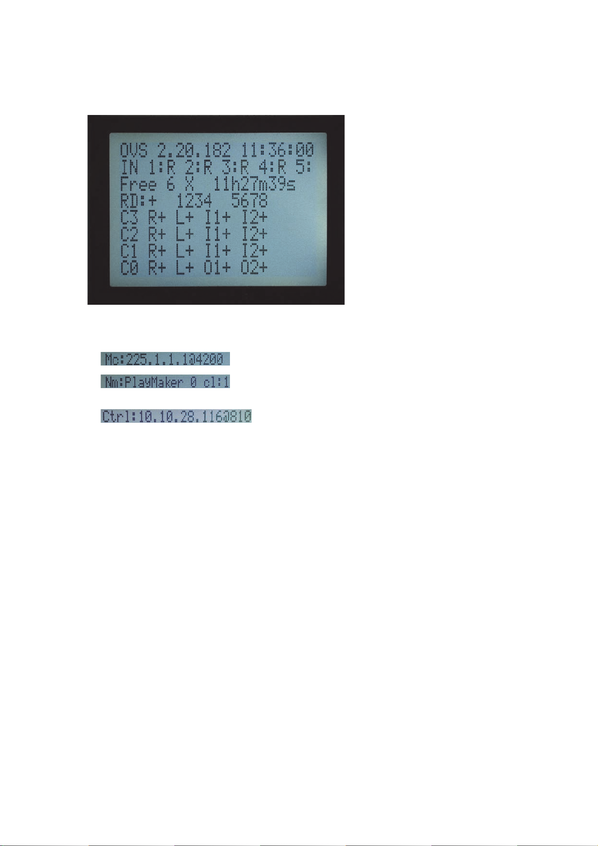
The PlayMaker LCD displays status information.
Line 1 alternates between: (application status)
• Server version, Time. Or-
• Mc: Server group IP address, Server group mask IP port
• Nm: Server name, Server number, Number of clients
connected to server (cl:1)
• Server IP address, Server IP port
Line 2 (application status)
• Status of inputs
- = no/bad inputs
\ / (slash back slash animation) = valid inputs, ready for recording
R/r = recording
If there is no valid software license, an alert is displayed in line 2, and no inputs are
displayed
Line 3 (application status)
• Number of available inputs, available recording time per input in hours, minutes,
seconds
Line 4 (application status)
• Raid status, status of disks 1-4, status of disks 5-8
1.Introduction
+: Raid controller is ready and functioning OK
A: Raid controller is alarming due to some problem
C: Raid critical problem
E: Raid error
O: Raid controller over heating
S: Smart error in one of the disks
The PlayMaker Server |
9
Page 10

-: Raid controller does not exist or is not identified
Disk stats:
Number: Disk at position # is OK
|: Ready - disk not protected by Raid
S: Disk smart fail
P: Spare disk
R: Disk is being rebuilt for Raid
-: Disk is offline
?: Disk state unknown
Line 5-8 (hardware status)
• I/O board, Reference status, LTC status, In1 signal status, In2 signal status
R+: reference signal OK
R-: No valid reference signal
L+: LTC signal OK
L-: no LTC signal
I1+, I2+ = valid genlocked signal (each input can display a different signal)
I1-, I2- = no valid genlocked signal
1.Introduction
10
The PlayMaker Server |
Page 11

TechnicalSpecifications‐Server
Mechanicalspecifications
• Rack 19" 3U
• Height 130mm
• Width 443mm
• Depth 631mm
• Weight 28kg (approx.)
Powersupply
Redundant power supply, 2X 460W (max) 100-240V 47-63hz
3Dstereoscopic
Dual link
VideoCODECs
SD DVCpro50,
1.Introduction
HD DVCpro100, DNxHD 145/120mbps
Recordingcapacity
SD (at 50mbps) Over 120 hours (at 50mbps)
HD (at 100mbps) Over 6
0 hours (at 100mbps)
AvailableI/Oconfigurations
2 channels, 4 channels, 6 channels, 8 channels
Extendedcapacity
SD Over 240 hours (at 50mbps)
HD Over 120 hours (at 100mbps)
Channelconfigurations
Fully Flexible
8in / 0out
7in / 1out
6in / 2out
5in / 3out
4in / 4out
The PlayMaker Server |
11
Page 12

3in / 5out
2in / 6out
1in / 7out
0in / 8out
Superslow‐motionconfiguration
In super slow-motion mode, each double speed camera will occupy two inputs, each
triple speed will occupy 3 inputs.
Double speed camera
4 channels
1 SSM in + 1 in > 1 out
6 channels
1 SSM + 2 in > 2 out
2 SSM > 2 out
8 channels
1 SSM + 4 in > 2 out
2 SSM + 2 in > 2 out
3 SSM > 2 out
Triple speed camera
4 channels
1 SSM in > 1 out
1.Introduction
6 channels
1 SSM + 1 in > 2 out
8 channels
1 SSM + 3 in > 2 out
2 SSM > 2 out
XSync,Frameaccuraterecording,Frameaccurateplayout
2 in / 2 out, Play while record
3 in / 3 out, Play while record
4 in / 4 out, Play while record
5 in / 5 out, Record, later Play
12
6 in / 6 out, Record, later Play
7 in / 7 out, Record, later Play
8 in / 8 out, Record, later Play
The PlayMaker Server |
Page 13

Audio
Embedded audio - PCM, Dolby E, ancillary data fully preserved
Up to 8 Uncompressed stereo audio tracks per video input channel
20bit or 24-bit / 48kHz
Analog audio - Up to 8 in and 8 out balanced stereo channels, using an external 2U
breakout box (AC-8), with software router for internal distribution
AES audio - Up to 8 in and 8 out balanced stereo channels, using an external 1U
breakout box (AES-8), with software router for internal distribution
Videoinputs
1 X SDI / HD-SDI per Video input
Loop 2 X SDI / HD-SDI per input - clean
Monitoring 2 X SDI / HD-SDI per input with OSD
Videooutputs
2 X SDI / HD-SDI per Video output
Monitoring 2 X SDI / HD-SDI per output with OSD
Genlock
Analog Black Burst / tri level
Auto detect
75Ωwith loop through
Timecodeinput
Internal free run
LTC - XLR
Embedded VITC / ATC (RP-188)
Timecodeoutput
VITC (of recorded Input TC)
Data interfaces
1.Introduction
2x Serial
4x USB (2 front / 2 back)
1x SATA
2x Ethernet (1Gb)
1x VGA maintenance (front)
1x XLR LTC input
The PlayMaker Server |
13
Page 14

GPI/O
64 inputs or outputs in flexible configuration Using 8-port external interface
Requires GPI/O Board Option
VDCP
8 X RS-422 using 8-port external interface
CPU
2 GHz Intel quad core Xeon
Operatingsystem
Linux
RAM
6 GB
Systemharddrive
2X 500GB mirrored
Internaldiskstorage
8 x 3"1/2 1TB SATA 2
1.Introduction
Or optional
8 x 3"1/2 2TB SATA 2
HardDiskRedundancy
Raid 6 striped disks with dual parity
Environmentalconditions
Operating temperature: 5c - 40C
Storage temperature: -40c - 70c
Humidity: 90% max
14
The PlayMaker Server |
Page 15
UnitInstallation
Step1:MountingtheServeronarack
■ Mount the Server on the rack using sliders and four rack screws. Verify that the
screws are secure, and that the workstation does not move.
CAUTION:
It is important to use all four screws, and not to overlook the back (inner)
screws.
Ventilation is handled through the sides of the unit; incoming air from the left, and
cooling fans on the right.
If the Server is installed in a closed or multi-unit rack assembly, the operation’s
ambient temperature of the rack may be greater than room ambient. Verify that the
temperature in the rack always stays within the 10C° to 35C° range.
CAUTION:
To prevent overheating, ensure there is enough room for ventilation.
Step2:ConnectingthePower
■ The Server has two power supplies. Connect two power cables, one for each power
supply.
DANGER:
To avoid the risk of electrical shock and fire, inspect the system power cord and
plug routinely. Ensure they are not damaged in any way.
CAUTION:
Make sure power connection includes reli a b le gr ou nd ing.
After the Server is mounted and secured, connect both power supply cables to the
power supply tray. Two power supplies give a back-up power source in case one incurs
a problem.
NOTE:
When one of the power sources ceases to function, an alarm sounds to alert you
that only one power source is in use. Press MUTE on the front panel to silence the
alarm.
Step3:ConnectingtheVideo
The Server must receive a valid reference (Genlock) signal.
When using an Analog GENLOCK source, you can connect one ANALOG REF plug as the
input and the other ANALOG REF plug will automatically serve as the output (Loop).
1.Introduction
When using Analog GENLOCK, always put a 75-OHM termination on the REF out.
Do not use a chained signal from other devices. Connect the video cables according to
your configuration.
The PlayMaker Server |
15
Page 16
Step4:ConnectingtheNetwork
■ The network (Ethernet) interface is used for communication between the Server, the
server controllers, and other network devices.
The Server includes two network interface cards (NIC) for communication with the
control host and general network.
Step5:PoweringUp
When all necessary connections have been completed and configured, switch on the
Server by pressing the POWER button on the front panel.
MaintenanceandServiceInformation
DANGER:
This unit has two connections to the main supply. For protection agai nst electric
shock, disconnect both electric cords before service.
CAUTION:
Do not remove the power module without glov es. T he c o ve r of th e power
module serves as a heat-sink for cooling. Temperature can reach 60°C under
full load condition. If remove d, put aside the power module until cool, and
prevent anyone from touching it until it is cooled.
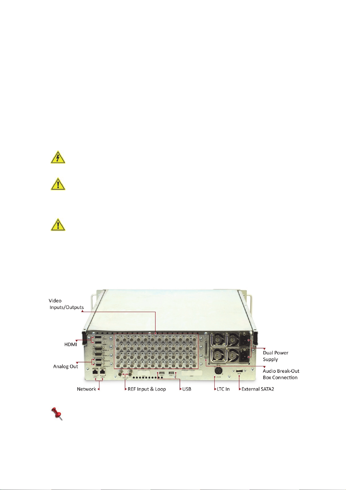
Connections
The back panel of the PlayMaker server is where all input and output connections are
1.Introduction
made. For information on the various possible wiring configurations, see Appendix on
page 113.
CAUTION:
Risk of explosion if lithium ba tt ery on motherboard is replaced by an incorrect
type. Dispose of used batteries according to the instructions.
16
NOTE:
By default, the left socket (LAN-1) is used for controls and connection to external
share-points, and LAN-2 is used for networking multiple servers.
The PlayMaker Server |
Page 17
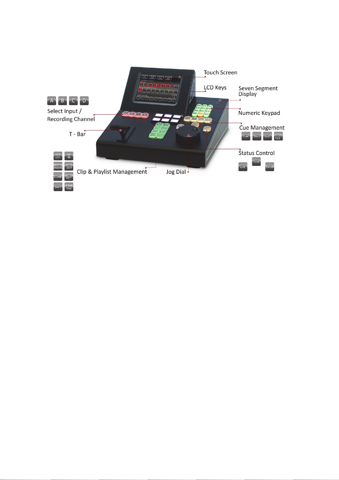
ThePlayMakerController
The PlayMaker Controller provides a full set of tools for instant replay and fast highlight
editing. The Controller’s main components are as follows:
1.Introduction
• Touchscreen display
• T-Bar on page 18
• Jog on page 18
• Programmable LCD Keys on page 18
• Keypads on page 19
• Back Panel - Connections on page 22
The PlayMaker Controller |
17
Page 18

TouchscreenDisplay
The controller is equipped with 5.7" (approx. 15 cm) color touch screen, with 640X480
pixel resolution. The touch screen capabilities eliminate the need for an external
keyboard or mouse.
T‐Bar
The T-bar is used to play instant replays, clips, and playlists with smooth control over
the play speed. The T-bar provides four different operation ranges, and can switch
instantly between two of the four options:
• 0% to 100%
• -100% to 100%
• -100% to 200%
• -200% to 200%
Primary and secondary ranges are set in the controller settings. Switching from
primary to secondary is done using SHIFT+T-bar.
In super slow motion cameras there is a 33% speed flat range at the middle of the
T-bar range.
Jog
The Jog dial allows you to search through the recorded video, field by field. The
number of fields per jog cycle is configurable. In fast jog mode, cycle speed is
multiplied according to the parameter selected during setup.
The Jog is also used to navigate playlists and clip lists.
1.Introduction
ProgrammableLCDKeys
Six programmable LCD keys provide different functionalities, and display the current
function name on the key as programmed, in the appropriate modes. Pressing SHIFT
provides up to six additional functions.
For an easier workflow, you can set a SmartEvent for each saved clip; during the
pre-game setup you will need to define SmartEvent types (see SmartEvents on
page 34). Then, during the game, you have the option to select a SmartEvent when
saving a clip, as a label (see To set a SmartEvent for the clip: on page 70).
Later in the game, pressing one of the SmartEvent keys will sort only the clips related
to the selected SmartEvent, for easy sorting and access.
18
The PlayMaker Controller |
Page 19

Keypads
The PlayMaker Controller has five different keypad areas, each dedicated to its own
purpose.
• The four Select Input/Recording Channel keys (marked A, B, C, D) are used for
switching between live or recorded input from different cameras. If more than four
inputs are configured, use SHIFT, A to access input 5, SHIFT, B to access input 6,
etc.
• The numeric keypad is used to save manually numbered clips, and load them, using
either clip numbers or timecode values, for creating and reloading playlists, and for
deleting clips and playlists.
• The cue management keys are used to play and navigate cues defined during the
game.
• The Status Control keys (LIVE, PVW, ENTER):
LIVE - when first pressed, LIVE starts recording all inputs configured to record that
have a valid input signal. When the system is recording the key turns red.
Pressing LIVE during recording shows the current selected live input on the active
output.
In replay mode, after setting an In or Out point, press SHIFT, LIVE to return to the
live input without deleting the marked points.
When a clip is loaded, press SHIFT, LIVE to switch from the clip to the recording, at
the same time stamp.
When the Server is not recording, press SHIFT, LIVE to switch back to live without
starting a recording.
PVW - Switch control to the preview channel, or to the second PGM channel,
according to your configuration. Blinks red as long as the selection is active.
1.Introduction
ENTER - generally used for saving marked In- and Out-points as clips, and to
confirm clip and playlist loading.
• The clip and playlist management keys are used to mark and store clips, and to
create and edit playlists.
The PlayMaker Controller |
19
Page 20

TechnicalSpecifications‐Controller
Datainterfaces
•1 Serial
•2 USB
•2 Ethernet (1Gb)
•1 VGA
Chassis
• Height - 180mm
• Width - 280mm
• Depth - 285mm
• Weight - 4.8kg (approx.)
Powersupply
60W (max) 100-240V 47-63hz
Environmentalconditions
Operating temperature: 5c - 40C
Storage temperature: -40c - 70c
Humidity: 90% max
1.Introduction
Other
CPU:Atom N270
Operating system: Linux
RAM: 1GB
System hard drive: 8GB solid state drive
LCD: 5.7" 640X480 TFT color touch screen
Push buttons: Illuminated, 3 million operations minimum
Input devices: Support for external USB keyboard & USB mouse
ControllerInstallation
Step1:ConnectingthePower
20
■ Connect the power cable.
DANGER:
To avoid the risk of electrical shock and fire, inspect the system power cord and
plug routinely. Ensure they are not damaged in any way.
The PlayMaker Controller |
Page 21
CAUTION:
Make sure power connection includes reli a b le gr ou nd ing.
Step2:ConnectingtheNetwork
■ The network (Ethernet) interface is used for communication with the Server.
Connect the network cable to right LAN port.
Step3:PoweringUp
When all necessary connections have been completed and configured, switch on the
Controller by switching on the POWER button at the back.
MaintenanceandServiceInformation
DANGER:
This unit has two connections to the main supply. For protection agai nst electric
shock, disconnect both electric cords before service.
CAUTION:
Do not remove the power module without glov es. T he c o ve r of th e power
module serves as a heat-sink for cooling. Temperature can reach 60°C under
full load condition. If removed, put aside the power module until cool, and prevent
anyone from touching it until it is cooled.
1.Introduction
CAUTION:
Risk of explosion if lithium ba tt ery on motherboard is replaced by an incorrect
type. Dispose of used batteries according to the instructions.
The PlayMaker Controller |
21
Page 22
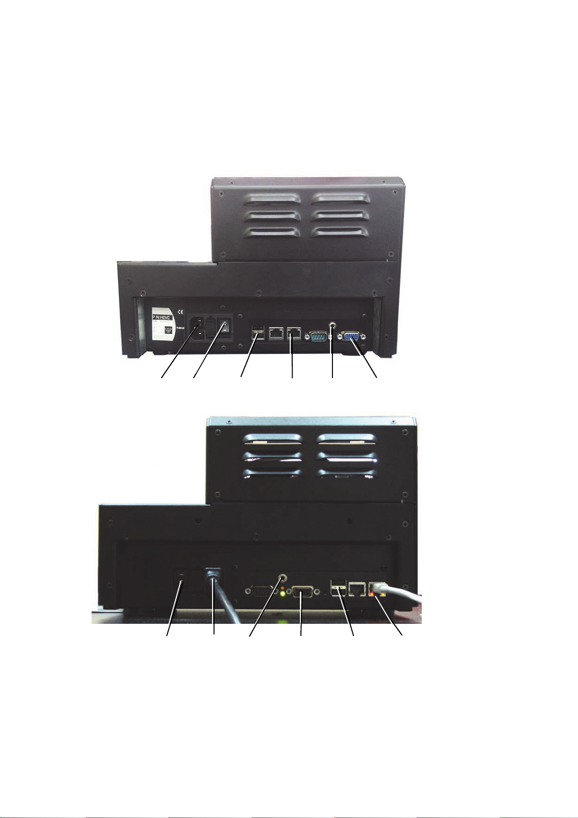
BackPanel‐Connections
Power
Switch
Power
Cable
Mini Jack
External VGA
Connection
Network
USB
port
Power
Switch
Power
Cable
Mini
External VGA
Connection
Network
Jack
USB
Port
The necessary Controller connections are made via the Controller’s back panel (two
models exist, both are shown below); a network connection, external VGA connection,
and the power cable. All other inputs (second network connection, USB X2, serial port)
are optional.
1.Introduction
22
The PlayMaker Controller |
Page 23
ConventionsUsedinthisManual
• Menu options and other on-screen items appear in bold lettering.
For example, “Tap the Video Standards option”.
• Keyboard keys appear in capital letters.
For example, “Press SHIFT, MENU to access the main screen.”
• LCD key options appear in capital letters and in italics.
For example, “Press SHIFT, LOOP to loop the clip when played.”
• “Tap” is used for interaction with the touch-screen
• “Press” is used for regular controller keys and LCD keys.
• NA = not applicable.
DANGER:
This symbol warns of the presence of dangerous high voltage.
CAUTION
This symbol cautions the user about improper handling, which might cause
damage to the hardware or software system. Data loss might result.
1.Introduction
Conventions Used in this Manual |
23
Page 24

1.Introduction
24
Conventions Used in this Manual |
Page 25

Inthissection:
The Main Screen on page 26
SmartEvents on page 34
OSD Data (Superimposed Data) on page 48
Shutdown on page 49
RAID Disk Replacement on page 50
License Installation on page 51
Software Upgrades on page 51
2.Basics
Working in Studio Mode on page 52
Managing Recordings on page 52
Page 26
TheMainScreen
2.Basics
Once the system is started, the main application screen is displayed. This screen
displays system information and serves as a portal to all Controller operations.
Application version and network information is displayed at the top left. Tapping this
data provides a quick view of the information, as follows:
Set 1 Controller IP, Server IP, Server group.
Set 2 Server name - server name with correlation to server serial number. For
example, HDVS-233.
Work mode - available modes are: PGMS_INDI (1 program output),
PGM_PVW (program/preview functionality), 2PGM_SPLIT (2 program
output).
Video standard - current video format.
Video CODEC - encoding/decoding compression format.
Video bit rate - current bit rate for the current video format.
Remaining recording time - total remaining time; before recording
begins, this shows the total available recording time. During recording, this
shows the total remaining recording time, divided by the number of
recording channels.
Set 3 TC source - current time code source. Available options are: Live (free
run, created internally by server), LTC (by XLR), VITC (embedded on video
input).
Genlock - current genlock type. Available options are: Bi-level (analog
black burst), TRI level.
Reference - reference status indication (OK/No signal).
LTC - LTC status indication (OK/No signal).
Audio groups - the mapped audio channels for video inputs. Each group
has four audio channels, only selected groups are recorded. Selecting a
group all of its channels on each video input.
It is recommended to record required groups only to save disk space, and
to avoid unneeded audio channels when exporting.
26
Set 4 USB mount - displays the connection status of the USB storage (import
and export) mounted to the Server.
Shared Folder - displays the connection status of the shared folders
(import and export) mounted to the Server.
Set 5 Software version
Server - Server software version
API - communication protocol version
Controller - Controller software version
GUI - user interface version
LIB - version of server middleware
Firmware - firmware version of the video board.
The Main Screen |
Page 27
To access the main screen from any other point:
■ Press SHIFT, MENU.
The following setup menus are displayed in the main screen.
• Video Settings on page 27
• Audio Settings on page 29
• Controller Settings on page 30
• In/Out on page 31
• Maintenance on page 32
• Data on page 33
• SmartEvents on page 34
• Network on page 39
• Export on page 40
Changes made in the menu take effect after you return to the main screen and tap
Apply & Start to confirm your changes. Some changes require the server application
to restart, which causes ongoing recordings to stop. In this case, the message on
button will be Restart to Apply Changes. To cancel changes, press Cancel.
2.Basics
NOTE:
If a connection to the server has not been established, only Controller and
Maintenance are available. All other options are disabled.
VideoSettings
To access the Video settings:
■ In the Main screen, select Video.
Video
Standard
PlayMaker can switch between video formats, without losing existing
footage. Switching between formats does not require any change in
server wiring. However, the system must stop recording and reload
different firmware. This process is automated, and takes
approximately 30 seconds.
To switch, select the required video format:
• SD PAL 50hz
• 1080i 50hz (HD)
• 720P 50hz (HD)
• SD NTSC 60hz
• 1080i 60hz (HD)
• 720P 60hz (HD)
The Main Screen |
Note:
3D stereo is configured from the in/out settings, according to
the selected video standard
27
Page 28
Video
Format
Phase Use the arrow touch keys to set synchronization of the horizontal and
Record TC Select timecode input source. This defines the timecode that is used
Set the required video format, and its options:
• DVC Pro HD
• DVC Pro SD
•DNxHD
Each CODEC will allow you to select a video format from the relevant
formats.
When changing video format, the appropriate firmware is installed by
the system. Therefore, switching video formats is a process that lasts
approximately 10 minutes.
Note:
3D stereo is configured from the in/out settings, according to
the selected video standard.
vertical signal phases of the server output.
Vertical phase range is +/- 540 lines, in 1 line intervals.
Horizontal phase can be adjusted by 1 line, in 1 pixel intervals.
(Default = 0).
to manage recordings. (LTC is recommended, if available).
• LTC - requires linear timecode input (XLR connector is available on
the server back panel).
• VITC - if available on embedded signal.
• Free run (internal system timecode)
2.Basics
If your TC source fails, the system automatically continuous from the
last known TC, and checks the source every five seconds to resume
usage.
28
The Main Screen |
Page 29
AudioSettings
To access the Audio settings:
In the Main screen, select Audio
Embedded
Inputs Distribution
Router
Output
Audio
Router
Audio Settings
Each input has the following options:
Use Router - uses the internal audio router to mix the AES and the
master embedded input.
Preserve - uses the original embedded input.
Set the router output to be Embedded (default) or AES/Analog.
This affects the way audio is recorded. Embedded - if the router
output is set to Embedded, the audio is recorded only to the
embedded channels, and played only from the embedded channels.
AES - if the router output is set to AES, the audio is recorded only to
the AES channels, and played only from the AES channels.
The audio router allows you to map the audio input sources for each
of the recorded video channels. Router embedded inputs come from
the master embedded channel (embedded audio on in1), or the
Analog AES external audio converter.
On each video channel, you can map both embedded and analog/AES
inputs onto the different stereo pairs.
Each audio channel is mapped as a stereo pair.
Each audio channel can be mapped once for each video input.
Audio router mapping can be recorded as embedded or as AES.
If recorded as embedded output is embedded audio; if recorded as
AES, it will be exported as AES audio.
Audio on Slow/Fast Motion - Set audio to play whenever video is
played (On) or to play only when the video is played at its normal
speed (Off, default). Monitor - audio on audio monitor only.
2.Basics
Router
Source
Audio Scrub on Jog - Toggle between: On- audio scrub on audio
output and audio monitor. Monitor- audio scrub on audio monitor
only. Off- no audio scrub.
Audio Meters - Toggle this option to display audio meters
superimposed on the output (On) or to hide the audio meters (Off).
Audio Monitor - Set audio monitoring for operator on: Controller
or none (Off).
Audio Monitor Channels - Define which audio channels will be
monitored. Default for monitor left is channel 1 and for monitor
right, channel 2.
Audio Monitor on Controller - Set which audio output to hear
when using audio monitoring; PGM, PVW, Active (current). Default
is Active.
Set the source of the audio router as required:
• Embedded
•AES/Analog
•AES+Embedded
• Mute (note: a muted channel is still recorded, and uses space on
the Server.)
The Main Screen |
29
Page 30
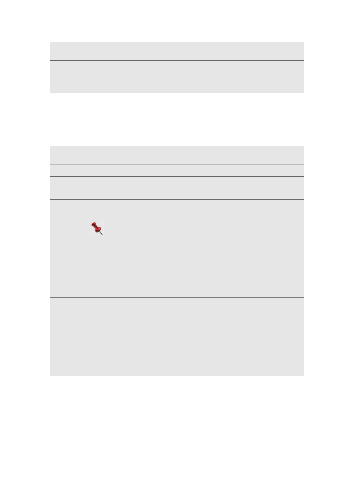
Audio
Levels
Adjust the volume of each input, as required; select the input at the
bottom, and use the arrows to adjust the level.
Recorded
Audio
Groups
Set the required audio groups to be recorded. There are four groups
defined in the audio router; channels 1-4, 5-8, 9-12, 13, 16. Any
audio channel not defined in this group or groups is not recorded by
the PlayMaker Server.
ControllerSettings
To access the Controller settings:
In the Main screen, select Controller.
Jog &
T-Bar
Cues See Cue Setup on page 62.
Clips See Clip Setup on page 79.
Playlists See Playlist Setup on page 92.
Control
mode
See Configuring the Jog on page 100 and Configuring the T-Bar on
page 102.
Set the way the Controller uses the PGM/PRV and/or PGM/PGM
channels.
Note:
You must set the Server’s Output Work Mode settings before you
can set the Controller’s work mode settings. (see page 32)
2.Basics
If you set PGM/PGM mode in the In/Out settings, you can set if you
want the Controller to control one output or both outputs (if you choose
2 outputs you can map which controls PGM 1, and which controls PGM
2.
Gang - when working in a 4in/4out setup, each input is mapped to its
corresponding output, and the Controller controls all channels
synchronously.
Studio
mode
Network Settings for Controller and Server addresses.
Select this mode On when each camera is a different game.
For more information, see Working in Studio Mode on page 52.
When you select Studio mode, the Studio settings option is displayed.
Set Clip list to Show All or Show by Input, and set Derived clips to
be created (Yes) or not (No).
Controller Address - set the IP address, IP mask, or whether to
enable/disable DHCP.
Server to Connect - set IP address (of the server to connect to), IP
port, and controller ID.
30
The Main Screen |
Page 31
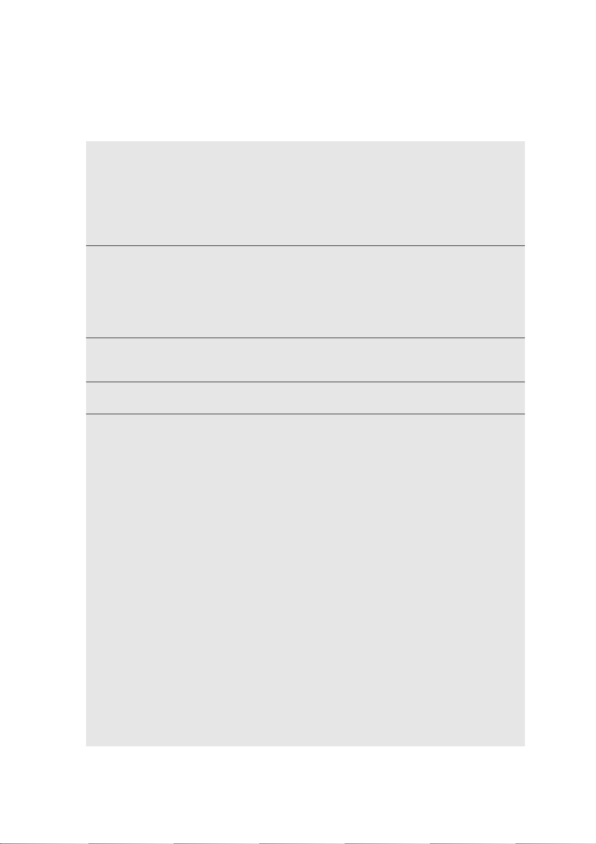
In/Out
To access the Input/Output settings:
In the Main screen, select In/Out.
Start/
Stop
Record
Record
Inputs
As
OSD
Settings
Preview
Output
I/O
Setup
Opens a screen to start or stop recording for selected or all configured
input cameras. A red background indicates that the channel is
recording, a blue background indicates that the channel will not be
recorded, a green background indicates that the channel is not
recording but will record when you next press LIVE. A green spot
indicates that the input signal is available and locked, and a red spot
indicates that there is no signal. You can start or stop recording by
tapping the CAM names.
Opens a screen to select a recording mode.
Sync Recording - all recordings are started simultaneously and can be
stopped separately. When you mark a clip on one channel, it is marked
on all channels (default).
Independent Recording - recording can be started and stopped
separately. When you mark a clip it is only marked on the current
channel.
Opens a screen where you can select to display or hide OSD data for
each output (Super - superimpose data, Clean - hide data).
For more information, see OSD Data (Superimposed Data) on page 48.
Set to display or hide the OSD data for each HDMI and component
output.
The following settings relate to the common 8-channel configuration:
Define how many inputs and outputs are used, and how they are
configured (regular, SSM, 3D, 4K/4sync).
Single Recorders -
4in/4out
6in/2out
7in/1out
5in/3out
8in/0out
0in/8out
1in/7out
2in/6out
3in/5out
Super Slow Motion - SSM50(or 60)+4in/2out
SSM50(or 60)+5in/1out
SSM75(or 90)+3in/2out
SSM75(or 90)+4in/1out
3 X SSM50(or 60) / 2out
2 X SSM75(or 90) / 2out
3D Stereoscopic -
4in (3D) / 0out (3D)
3in (3D) / 1out (3D)
2in (3D) / 2out(3D)
1in (3D) / 3out (3D)
0in (3D) / 4out (3D)
4k/4sync - to record a synchronous recording.
2in, 2out, 1in/1out (1080i).
2.Basics
The Main Screen |
31
Page 32
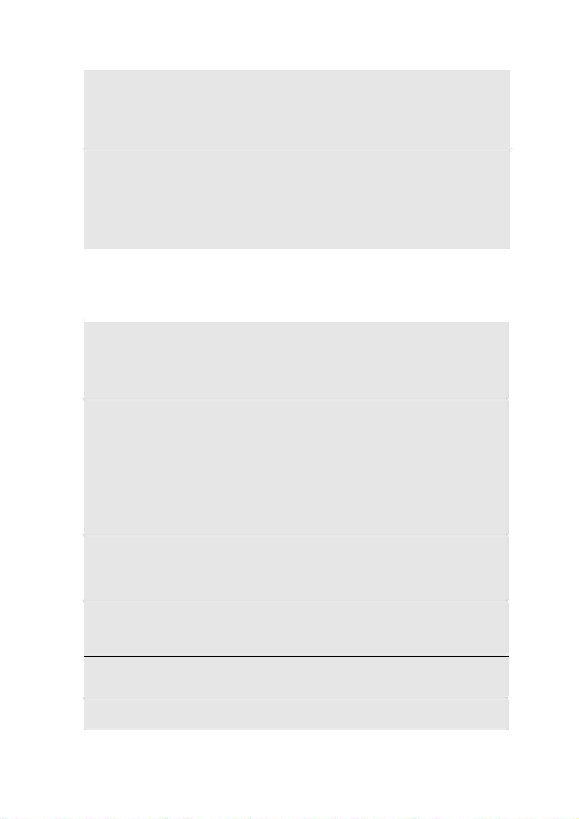
Rename
Inputs
and
Outputs
Rename Inputs - opens a screen to select an input camera for
renaming. Tap the option to open a virtual keyboard and enter the
required name. The new name is reflected in the camera name on touch
screen, and on the OSD data.
Rename Outputs - Open a virtual keyboard to set the name of the
output channel. This name is displayed the OSD data.
Maintenance
To access the Maintenance settings:
2.Basics
Output
Work
Mode
In the Main screen, select Maintenance.
Diagnostic Export Diagnostics Log - export the diagnostics log to a USB device
Storage Clean Video Disks - Use this option to erase all existing data from
Set the output mode to PGM/PVW, separate PGMs, or Gang mode.
PGM/PVW display allows you to control outputs simultaneously or
separately, and can transition between the outputs with an effect.
Two PGM mode allows you to have independent outputs. When you
choose this option you must configure the primary and secondary
output. For more information, see Output on page 56.
When working in Gang mode, each input is mapped to its corresponding
output, and the Controller controls all channels synchronously.
connected to the Controller. This log contains data on the current
system status.
Export Automatic Log - export the automatic log to a USB device
connected to the Controller. This log is created automatically if a crash
occurs.
the disks (in all formats). This removes all cues, clips, playlists, and
actual video recordings from the disks.
After this command is started, video will no longer be accessible. This
option also deletes lock and protected clips and playlists.
RAID Status & Info - RAID board status.
RAID Disk Status - Reflects the status of each disk; Green for fully
operational, Yellow for disk problems, Red for disk failure, Blue for
replaced disk (until recovery). For more information, see RAID Disk
Replacement on page 50.
RAID Alarm - enable or disable the audio alarm for RAID failure.
32
Network Set Server IP - set the IP address of the Server.
Server Group IP Address - set the group IP address. This must be
identical for all servers in the network.
Server Group IP Port - This must be identical for all servers in the
network.
License View the status of the licenses required for the various components of
you system. From this screen you can renew licenses using license
files provides by Orad. For more information, see License Installation
on page 51.
Version
Control
Date and
Time
Displays information about the current hardware and software
versions of the server, controller, and other system components. For
more information, see Software Upgrades on page 51.
Set system time (24 hour format), date (DD-MM-YY). Changes made
here must be applied when finished.
The Main Screen |
Page 33
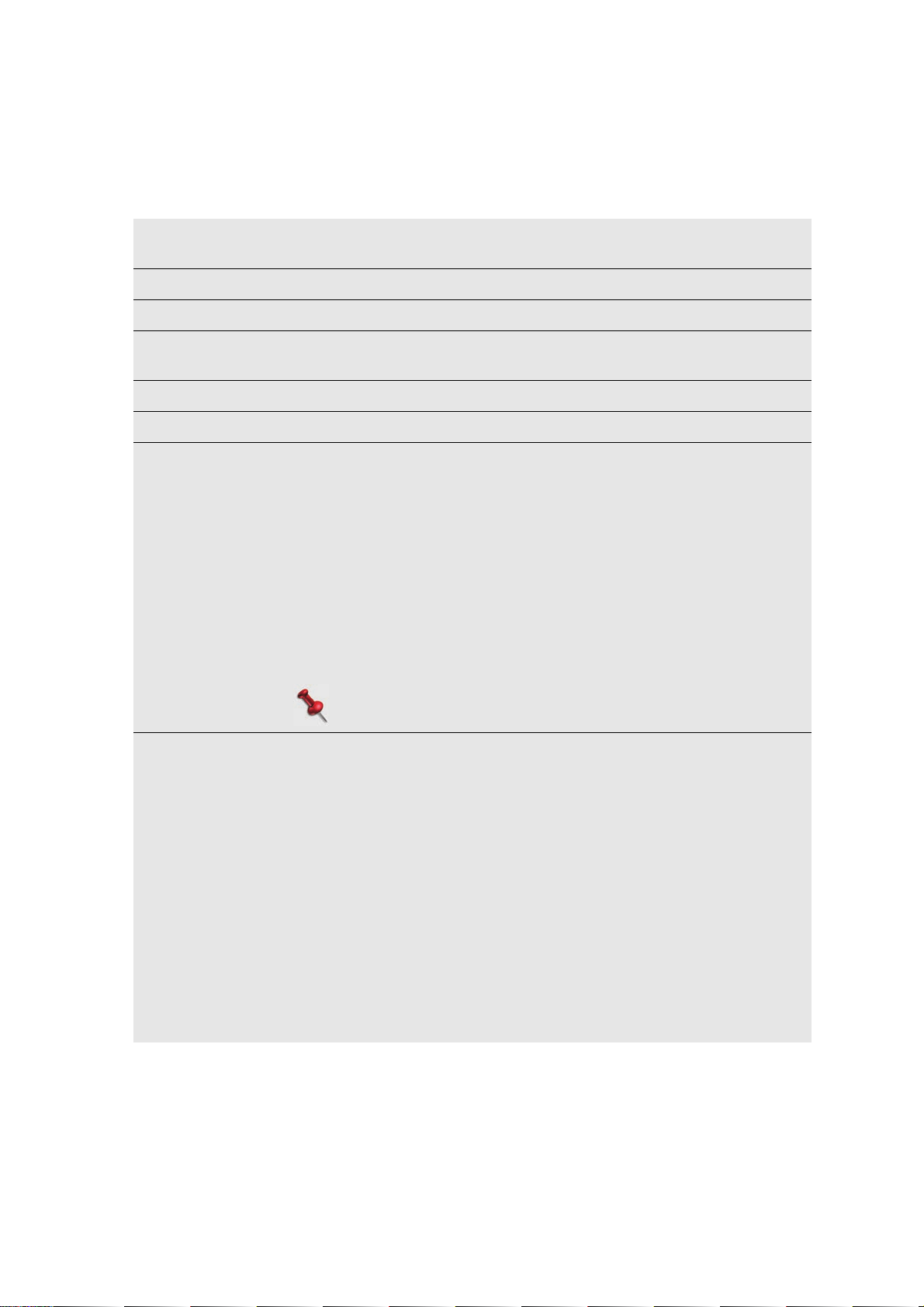
Data
To access the Data settings:
In the Main screen, select Data.
Clear all
unlocked data
Clear all cues Delete all cues.
Clear all clips Delete all unlocked clips (that are not used in a playlist).
Clear all
playlists
Lock all clips Lock all clips to protect them from deletion.
Unlock all clips Unlock all clips to allow them to be deleted.
Strip
Recordings
Delete all unlocked cues, clips, and playlists.
Delete all playlists.
Set the following strip recording options (for more information,
see Stripping a Recording on page 46):
Keep Derived - set Yes to save the primary clip and all of its
derived angles. Set No to save the primary clip only. For more
information, see About Clips on page 66.
Keep Safety Clip Zone - set Yes to save the clip’s safety zone.
Set No to discard the safety zone. For more information, see
About Clips on page 66.
Strip Ongoing Recording - select Yes to strip ongoing
recording. Set No to disable stripping.
Recording Safety Tail - define the number of hours from the
end of the recording that is not stripped.
2.Basics
Note:
Safety tail is valid for ongoing recordings only.
Record Mode Set what happens when there is no empty disk space for
recording;
Standard recording - the recording is stopped. Remaining
recording time indication in the OSD blinks if the remaining
recording time is less than 30 minutes.
Cyclic recording - the server overwrites the earliest possible
materials. Areas in previous recordings which are within any of
the saved clip boundaries are protected and will not be
overwritten. See Loop Recording on page 43.
Auto Start - When auto restart is OFF, after 24 hours, the server
automatically stops recording. (Recording must be restarted
manually.) When auto restart is ON, after 24 hours of recording,
the server stops the current recording and will start a new
recording. The gap between recordings will be less than one
second. For more information, see Round the Clock Recording on
page 43.
The Main Screen |
33
Page 34

SmartEvents
The SmartEvents option is used for tagging a clip according to meta-data keywords
that you set. Some of these tags appear on the LCD buttons in Live/Replay mode (after
setting an in-point), and the tag that is displayed alongside the clip number, in the clip
list view. For example, you can tag a clip as a goal, or by player, or both. Only one
SmartEvent group can be active. You can set keywords prior to or during the
production.
Choose one of three SmartEvent modes to use for marking clips:
• Set a single SmartEvent for a clip from the 12 options displayed on the LCD keys.
(Not controller dependant.)
•Set multiple SmartEvents for a clip from the 150 options displayed in the touch
screen (six active pages with 25 options, each).
•Set a single SmartEvent for a clip from the 150 options displayed in the touch
screen (six active pages with 25 options, each).
NOTE:
Each controller can create and run different groups, and different
SmartEvents, even if they are running on the same server, but the
SmartEvents are saved in the server Data base, not on the controller.
PlayMaker can manage up to 6 groups, each group can manage up to 6 active pages,
each page can manage an unlimited number of SmartEvents, but only 25 of them can
be displayed to the operator at once.
2.Basics
34
SmartEvents |
Page 35
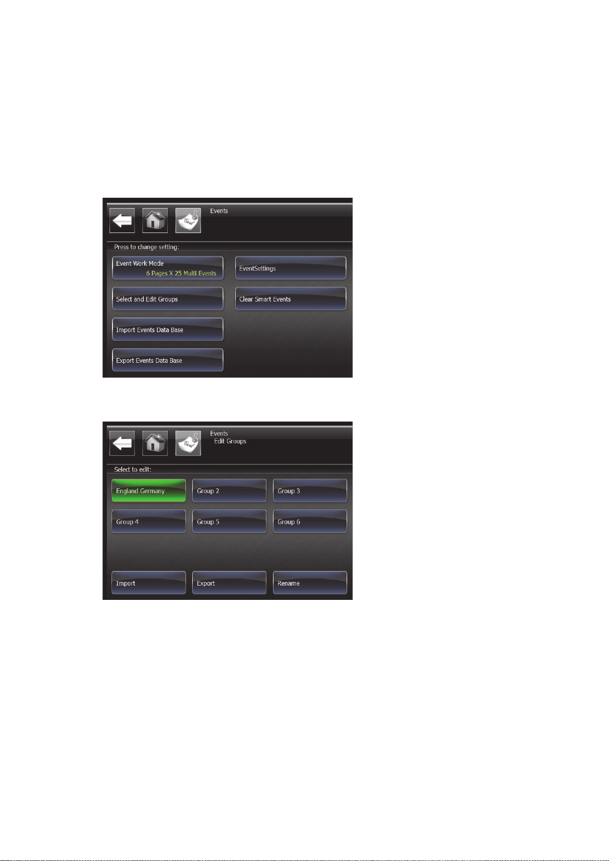
Groups,Pages,andSmartEvents
By tapping a group or page name (that is, when it is marked green), it becomes the
active group/page.
To set group names:
1. In the Main screen, tap SmartEvents.
The SmartEvent options are displayed.
2. Tap Select and Edit Groups.
The SmartEvent groups are displayed.
The currently selected group is green.
3. Select a group and tap Rename.
The Virtual keyboard is displayed.
4. Type in the group name, and then tap Enter.
2.Basics
For more information, see Using the Virtual Keyboard on page 44.
The group now displays the new name.
To open a group and edit its pages and SmartEvents, tap the required group twice.
SmartEvents |
35
Page 36
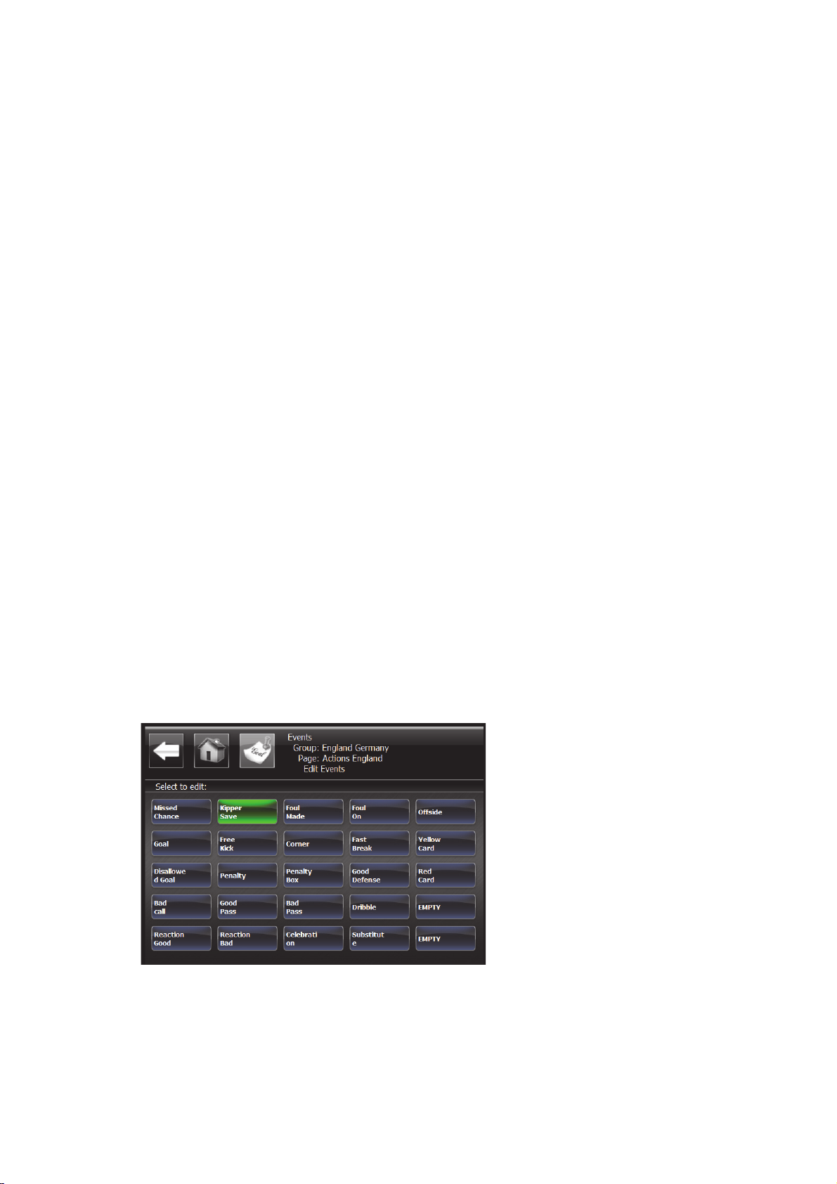
To set page names:
1. In the Main screen, tap SmartEvents > Select and Edit Groups, then tap the
required group twice to open it.
The pages are displayed.
2. Select a page and tap Change.
The Edit Pages screen is displayed.
3. Tap Add New.
The Virtual keyboard is displayed.
4. Type in the page name, and then tap Enter.
The name is added to the list of names.
5. Tap Apply.
The page is renamed.
To open a page and edit its SmartEvents, tap the required page twice.
You can create an unlimited number of pages (in the list of names), but only six can
be active at once.
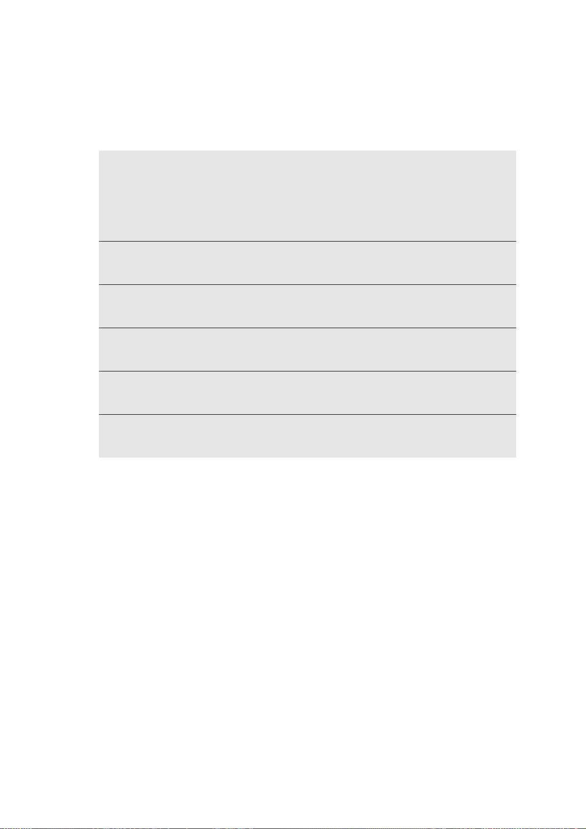
To set SmartEvent names:
1. In the Main screen, tap SmartEvents > Select and Edit Groups, then open the
required group and page.
2. Tap a SmartEvent to rename it.
2.Basics
The SmartEvents screen is displayed.
3. Tap Add New.
The Virtual keyboard is displayed.
4. Type in the SmartEvent name, and then tap Enter.
The name is added to the list of names.
5. Tap Apply.
The SmartEvent is renamed.
36
You can create an unlimited number of SmartEvents (in the list of names), but only
25 can be active at once.
SmartEvents |
Page 37

ImportingandExportingSmartEvents
You can import SmartEvents that were created on other servers, or export
SmartEvents for use on other Servers with their group/page hierarchy.
Group files are saved with the .SEG extension.
Page files are saved with the .SEP extension.
To import SmartEvents:
1. In the Main screen, tap SmartEvents > Import SmartEvents Database.
The available options are displayed with a blue background.
2. Tap the required source to import from.
3. Select the required file using the Jog or the PREV or NEXT LCD keys.
4. Press ENTER.
To export SmartEvents:
1. With a USB device connected, in the Main screen, tap SmartEvents > Export
SmartEvents Database.
2. Tap Export to USB Storage.
The SmartEvents are exported to the device.
2.Basics
SmartEvents |
37
Page 38
SmartEventOptions
To access the SmartEvent settings:
In the Main screen, select SmartEvents.
2.Basics
SmartEvent
Work Mode
Select and Edit
Groups
Import
SmartEvents
Database
Export
SmartEvents
Database
SmartEvents
Settings
Clear
SmartEvents
Set the required SmartEvent work mode;
6 Pages X 25 Multi Events - set multiple SmartEvents for
each clip from the touch screen, from any active page.
6 Pages X 25 Single Events - set a single SmartEvent for
each clip from the touch screen.
12 Single Events - set a single SmartEvent for each clip from
the 12 options displayed on the LCD keys.
Set names of the different groups, pages, and SmartEvents,
select the active group/name, import and export
SmartEvents.
Import SmartEvents from a USB device or a remote server
(.SEG or .SEP extension).
Export events to USB device.
On New In/Out Point - (open top left, open last, only by
user)
Names Over Events - (yes, no)
Clear all groups, pages, and SmartEvents from the Server
database, including SmartEvents which have been used to tag
existing clips.
38
SmartEvents |
Page 39

Network
To access the Network settings:
In the Main screen, select Network.
Net Settings NET Mode - Enable the Server to be part of the defined
Network, or Disable networking capabilities.
Server Name - open the virtual keyboard to enter the Server
name, as it will be displayed to other Servers.
Server Number - open a virtual keyboard to define a Server
number. Each Server number in the network must be unique.
Clips Copy Safety Zone - set Yes to copy the a clip’s safety zone
when copying clips from a remote server, or No to copy the
clip without its safety zone.
Copy Derived Clips - set Yes to copy the a clip’s derived
clips when copying clips from a remote server, or No to copy
the clip without its derived clips.
Net Clip Names - set naming options for imported clip names
in the clip list.
Lists Not supported in current version.
Recordings Not supported in current version.
Net Edit Not supported in current version.
2.Basics
Network |
39
Page 40

Export
To access the Export/Import settings:
In the Main screen, select Export/Import.
2.Basics
Set Export
Shared Folder
Set Import
Shared Folder
Enable Mount - enable connecting to the shared directory’s
export folder.
Protocol - set the communication protocol to use when
retrieving clips from the shared directory (CIFS, SMBFS,
NFS/AFS).
Shared Folder - open the virtual keyboard to enter the name
of the shared directory for exporting clips. A folder with this
name must exist on the remote computer with permissions for
the relevant user name.
Remote Computer - open the virtual keyboard to enter the
remote computer IP address where the shared directory
Export folder is located.
User Name - open the virtual keyboard to enter the user
name for the computer where the shared directory Export
folder is located.
Password - open the virtual keyboard to enter a password for
the computer where the shared directory Export folder is
located.
Domain - open the virtual keyboard to enter the domain
name, when there is a domain name in use.
Enable Mount - enable connection to the shared directory’s
import folder.
Protocol - set the Windows/Mac-Linux communication
protocol to use when copying clips to the shared directory
(CIFS, SMBFS, NFS/AFS).
Shared Folder - open the virtual keyboard to enter the name
of the shared directory for importing clips.
Watch folder - configure watch folder (auto import) options.
For more information, see Auto Import Settings on page 42.
Remote Computer - open the virtual keyboard to enter the
remote computer IP address where the shared directory
Import folder is located.
User Name - open the virtual keyboard to enter the user
name for the computer where the shared directory Import
folder is located.
Password - open the virtual keyboard to enter a password for
the computer where the shared directory Import folder is
located.
40
Export |
Page 41
Auto Export Auto Export - when Active the server will export every new
clip into the shared folder or USB device.
Device - define USB device or a network location as shared
directory.
Export Margin - auto export according the clip number.
When set to All all new clips are automatically exported.
Under Margin exports only clips which are numbered lower
than the selected margin. Above Margin exports only clips
which are numbered lower than the selected margin. The
default margin point is 500. When above Margin or below
margin are selected, tap Margin to change the margin
number.
Re-export on changes - export (an already exported) clip to
the shared directory if its In or Out-points are changed or if
the default input (master) for displaying the clip is changed.
Overwrite - set Yes to overwrite clips of the same name, or
No to save a new clip with the same name.
Export
Settings
Group to
Export
Export Format - select the file format to be used: Quicktime
(MOV), MXF Op1A, MXF OpAtom, PlayMaker REC.
Note:
PlayMaker REC is an internal PlayMaker format, used to
back up server files, or to move files from server to server
with an external device. REC files can only be played by a
PlayMaker server running a similar CODEC and video
format, and similar version.
Derived Angles - set Yes to export all derived angles (clips)
when exporting a clip to the shared directory, or No to export
only the master clip.
Safety zone - set Yes to export safety zones when exporting
a clip to the shared directory, or No to export only the clip.
Export Name - Set the naming options for exported clips.
Include Metadata - set Yes to export clips with all
metadata, or No to export clips without metadata.
Overwrite - set Yes to overwrite clips of the same name, or
No to save a new clip with the same name.
Start Clip - open the virtual keyboard to enter the number of
the first clip in the group for export.
End Clip - open the virtual keyboard to enter the number of
the last clip in the group for export.
There is a limit of 200 clips per group.
2.Basics
Export |
41
Page 42
AutoImportSettings
You can set PlayMaker to automatically import files from the Import folder using the
Watch Folder option.
To set Watch Folder Options:
1. In the Main screen, select Export/Import, and then Import Shared Folder >
Watch Folder.
2. Set the following options:
Auto Import Select Yes to set PlayMaker to activate the watch folder, to
import any files placed in it, or No to deactivate the watch
folder.
Scan Interval Set the time interval between each time the import folder is
checked for changes.
Scan Method Set which files in the folder to check: Only New Files to
import files added to the watch folder after the initial scan, or
All Files to import all files in the watch folder (provided the
watch folder is active).
2.Basics
Re-Import on
File Change
File Safety
Delay
Scan
Subfolders
Source File
Action
Set what action to take when a file is replaced in the Import
folder;
Yes, import and replace - to overwrite a changed file in
PlayMaker.
Yes, import as new file - to import the changed file with a
new name.
No - to take no action when a file is changed in the Import
folder.
Set the safety time interval to check for changes in new file
size. Import begins only after files size has not changed
between checks.
Select Yes to scan any subfolders contained in the Import
folder (and import according to the configured options), or No
to disregard subfolders.
Select what to do with the files in the Import folder after they
are imported to PlayMaker;
Keep - leave the source files in the Import folder.
(This is the only option available in the current version.)
42
Export |
Page 43
Recording
To start recording:
1. After booting the Server, press Start in the main screen.
2. Press LIVE.
Recording begins, for the configured cameras and runs until it is stopped, or there is
no more space left to record, or unless you make a change to the system
configuration that requires the Server to restart. Pressing the LIVE key during
routine operation does not affect the recording.
To stop recording:
■ See Start/ Stop Record on page 31.
LoopRecording
You can loop the recording to automatically strip the earliest possible footage, when
the server runs out of space (leaving any marked clips) by working in Cyclic recording
mode.
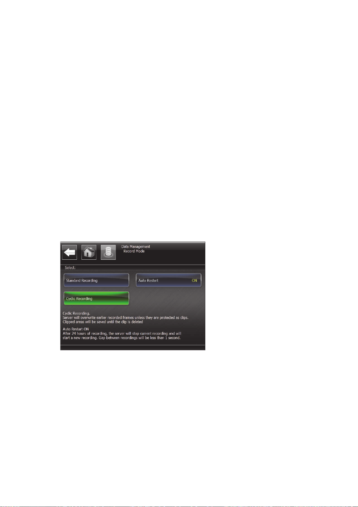
To set cyclic recording:
1. From the Main screen, select Data > Record mode.
2. Select Cyclic Recording.
RoundtheClockRecording
PlayMaker recordings have a 24 hour recording limit. Auto restart allows you to set the
server to start a new recording when the previous one has reached its 24 hour limit.
The time gap between the recordings will be less that 1 second. This can be used in
Standard and Cyclic recording modes.
2.Basics
To set auto restart:
■ From the Main screen, select Data > Record mode and tap Auto Restart to set to
ON.
Export |
43
Page 44
UsingtheVirtualKeyboard
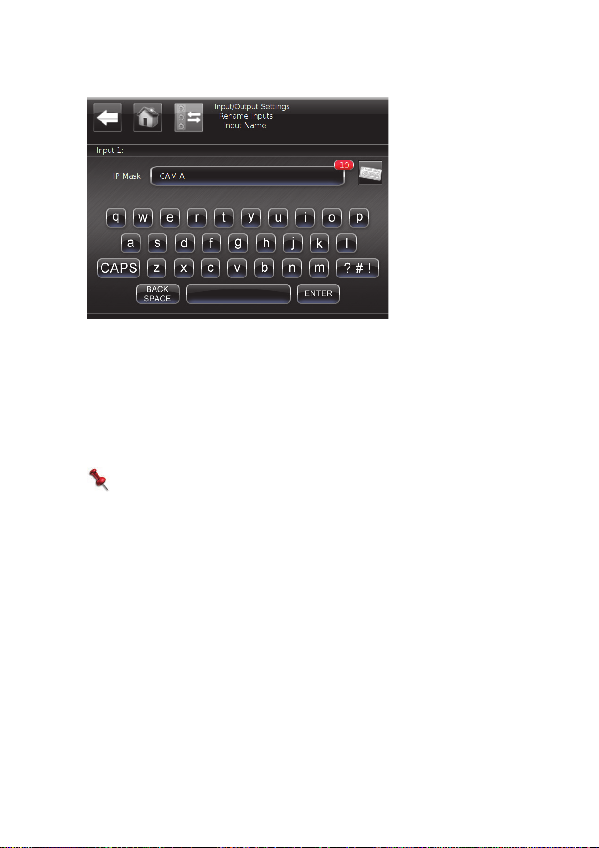
At various times during the workflow and during setup, a virtual keyboard is available
for naming or renaming purposes.
Tap the letters in the QWERTY keyboard to type them. The number of remaining
characters is displayed next to the text line.
2.Basics
The CAPS key functions as a SHIFT/CAPS LOCK key in a standard keyboard; tap once
for a single capital letter, or twice for Caps Lock.
To display digits and other special characters, tap ?#! .
When you’ve entered the required text, tap ENTER to return to the previous screen.
NOTE:
Connecting an external USB keyboard to the controller allows you to perform the
same action from both keyboards.
44
Export |
Page 45
AudioRouting
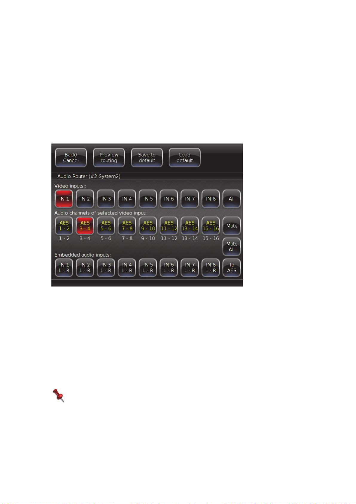
The Audio Router settings allow you to route AES/analog and embedded audio
channels, into the different video channels. For example, you can route the embedded
audio of one video input into some of the other inputs, or use each of the AES or
analog audio channels for several video inputs. You can mix embedded audio and AES
inputs into one video channel. For more information, see Audio Router on page 29.
To set the audio routing:
1. In the main screen, tap Audio > Audio Router.
The settings screen is displayed.
2. Tap the video input for which you want to set the audio output (1st row).
You can select more than one input for which to set the output.
3. Tap the audio channel to which you want to re-route (2nd row).
4. Tap the audio channels that you want to route into the selected audio inputs (3rd
row).
5. If required, toggle the right button to select the audio source type; AES or
Embedded.
6. Tap Save to default.
The available default sets are displayed.
7. Select a default group, and click Save routing to group.
NOTE:
System1 (master embedded channels to all video channels), System2 (all
analog/AES channels to all video channels), and System3 (analog/AES channels
to different video channels) are preset and cannot be changed.
Select a default, and tap Confirm actions. (Router must be enabled in the
Embedded Inputs Distribution settings, see page 29.)
2.Basics
Export |
45
Page 46

StrippingaRecording
Stripping a recording allows you to delete recorded footage while preserving any clips
that you have marked, freeing additional storage space. The recording is still displayed
in the list of recordings as disabled (gray). If you delete this disabled recording, the
clips will no longer be available.
Set stripping preferences in the Data menu on page 33.
To strip a recording:
1. Press MENU three times to display the list of recordings.
2. Use the Jog to select a recording.
3. Press the STRIP REC LCD key.
A confirmation message is displayed.
Note
Once you strip a recording, the action cannot be undone and the stripped footage
is no longer accessible.
4. Press ENTER to confirm stripping the recording, or CLR to abort the action.
PlayMaker strips the recording, keeping all marked clips. The clips keep their
original number and name, original time code, and all added metadata. Each clip
will be available from all recorded angles (if so specified). The stripping process will
not affect prepared playlists.
2.Basics
46
Export |
Page 47
GoToTimecode
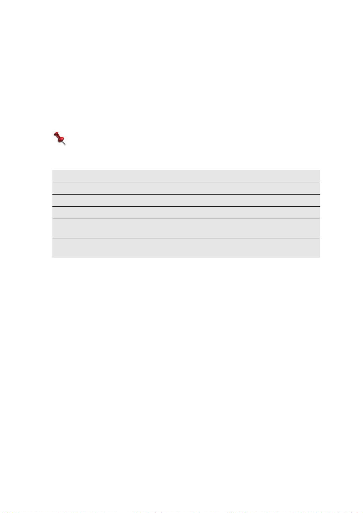
Jump to any point on the video quickly, using the timecode.
To jump to a point:
1. Press SHIFT, TC.
2. Enter the required timestamp (HH:MM:SS) using the numeric keypad.
3. Press ENTER.
The selected timestamp on the recording is displayed.
NOTE:
If multiple recordings exist wit h t he s ame timestamps, the latest recording is
loaded.
When you press SHIFT, TC, the LCD keys display the following options:
+5 minutes Forward the replay five minutes from current timestamp.
- 5 minutes Rewind the replay five minutes from current timestamp.
+1 hour Forward the replay one hour from current timestamp.
- 1 hour Rewind the replay one hour from current timestamp.
Start of
Recording
End of
Recording
Go to the start of the current recording.
Go to the end of the current recording (to the last current frame).
TheCLRKey
The CLR key in the numeric keypad has a number of functions. Use it for the following:
• To clear the Seven Segment display.
To delete a clip:
1. Press MENU to display the list of clips.
2. Press CLR and type in the clip number.
3. Press ENTER.
To delete a playlist:
1. Press CLR, LIST.
2. Type in the playlist number.
3. Press ENTER.
OR
2.Basics
1. Press MENU twice to display the list of playlists.
2. Select the playlist.
3. Press CLR.
4. Press ENTER.
Export |
47
Page 48
TheMENUKey
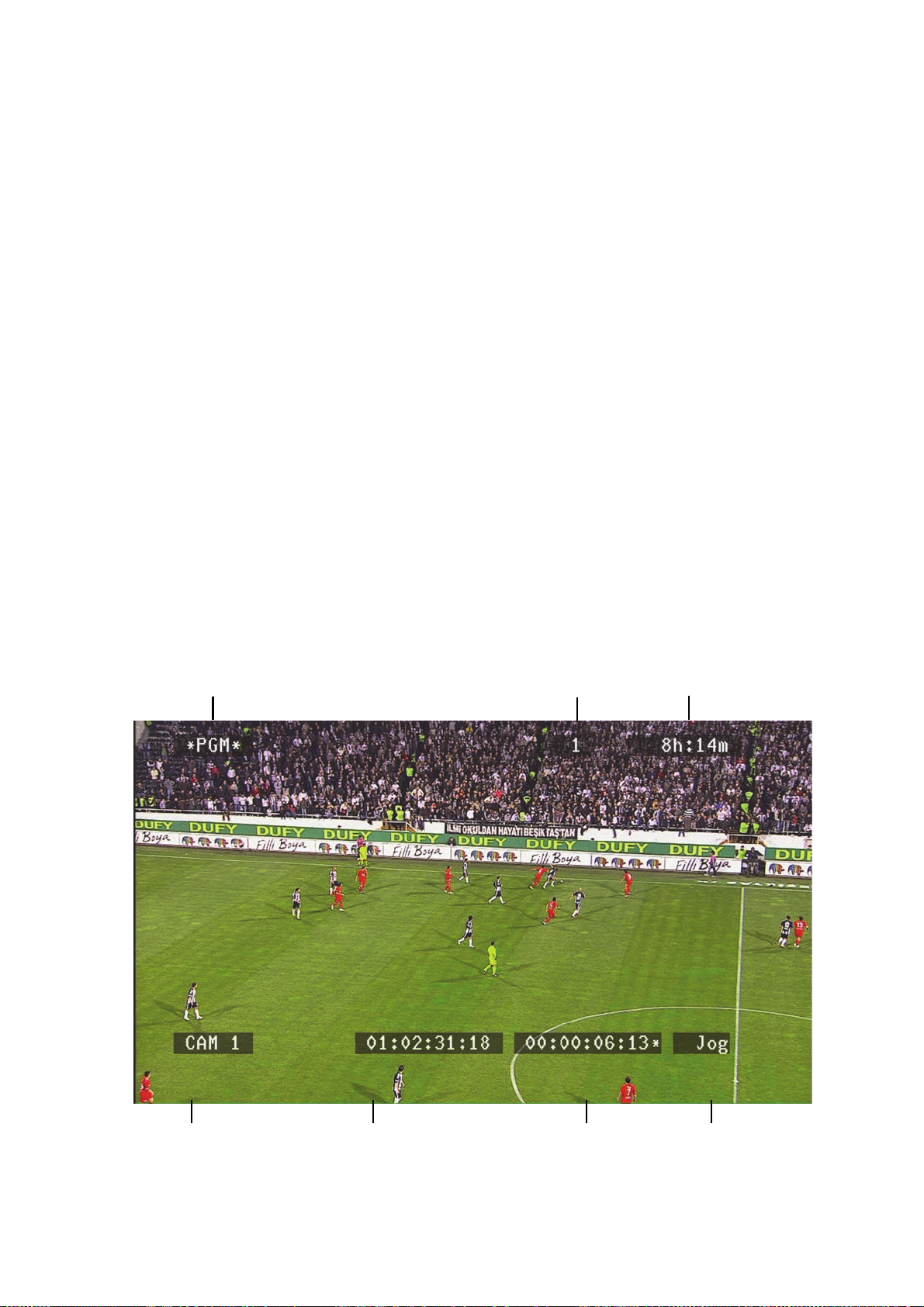
Output
Channel - asterisks indicate active channel
Remaining
Recording Time
Input Current Timestamp Time from In-point Control
Cue Number
• Pressing MENU once displays the list of clips. (If you load a clip from the list, the list
closes.)
• Pressing MENU twice displays the list of playlists. (If you load a playlist, the list
closes; If you press MENU when a playlist is loaded, the list of playlists opens
directly.)
• Pressing MENU three times (or three times on a single Server) displays a list of
recordings.
OSDData(SuperimposedData)
PlayMaker displays on-screen information for each output. You can hide this
information or select what to display.
To set OSD preferences:
■ See OSD Settings on page 31.
For more information, see:
• OSD Data for a Loaded Clip on page 74.
• OSD Data for a Playlist on page 84.
OSDDataforLive/Replay
2.Basics
48
OSD Data (Superimposed Data) |
Page 49
Shutdown
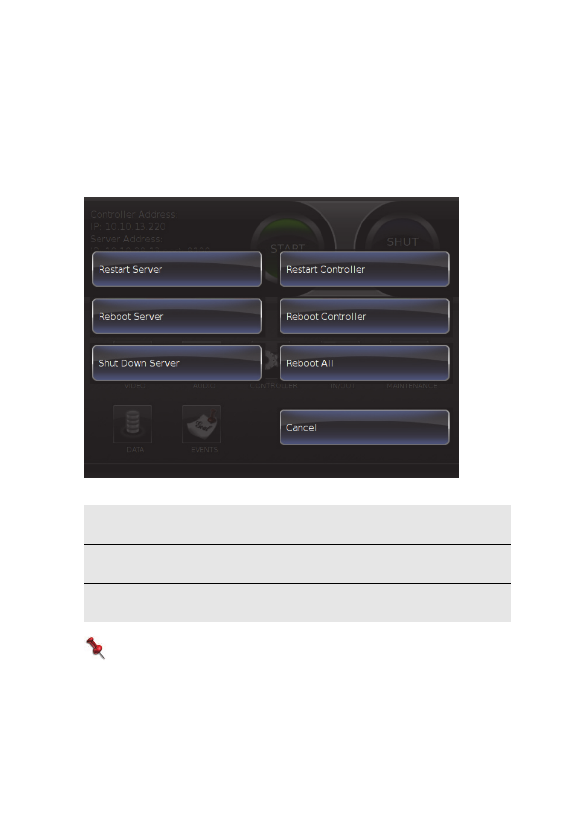
System shutdown options are available on the controller, for the server and the
controller.
To access shutdown options:
■ In the Main screen, tap SHUTDOWN.
The following options are displayed:
Restart Server Restart the server application.
Reboot Server Reboot the server unit.
Shutdown Server Power off the server.
Restart Controller Restart the controller application.
Reboot Controller Reboot the controller unit.
Reboot All Reboot the server and the controller.
NOTE:
To switch the Controller On or Off, use the power button on the back of the
Controller.
2.Basics
Shutdown |
49
Page 50
RAIDDiskReplacement
RAID disk replacement is done from the Server’s front panel, following the instructions
displayed on the Controller.
To replace a RAID disk:
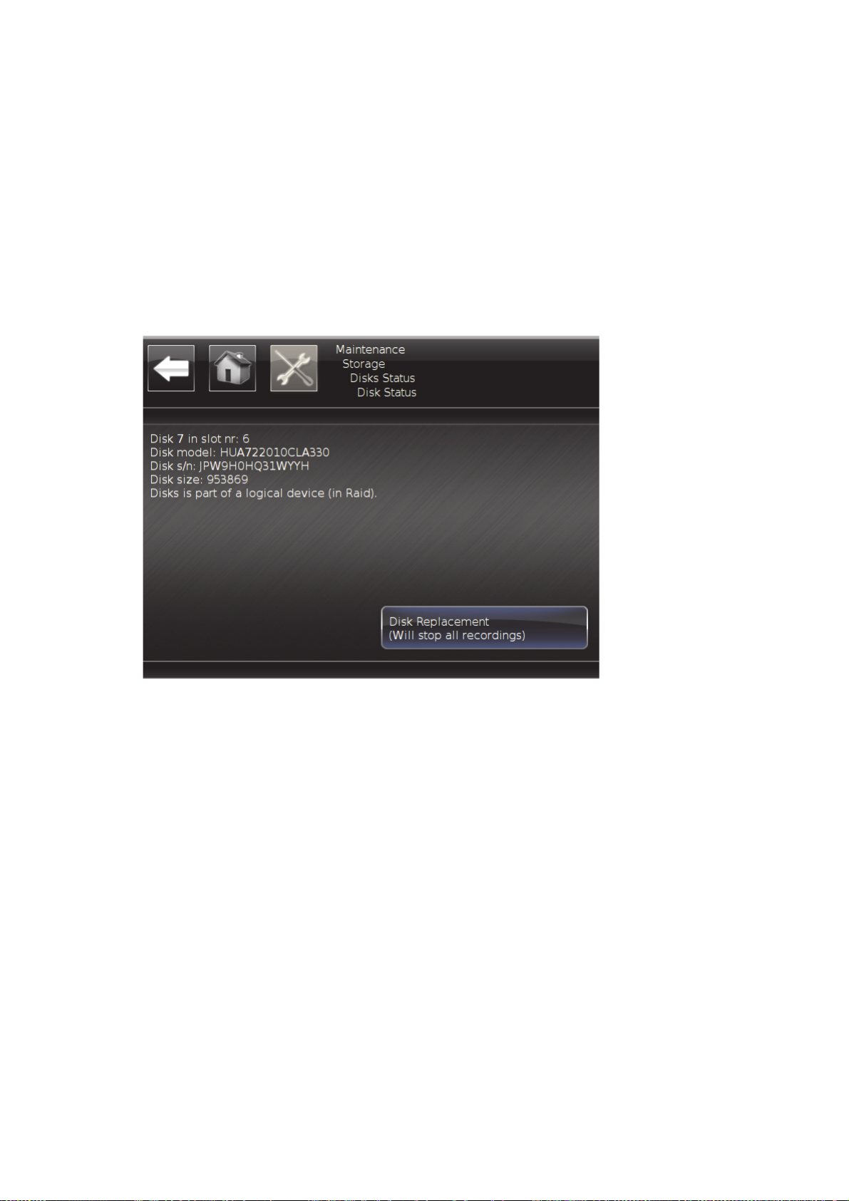
1. In the main screen, tap Maintenance > Storage > RAID Disk Status.
Status for each disk is displayed.
2. Tap the disk to be replaced.
The status screen is displayed.
2.Basics
3. Tap Disk Replacement, and follow the on-screen instructions.
4. When you get to the Start Disk Recovery screen, choose one of the following
options:
Full Disk Recovery - will recover all previous recordings that were on the old RAID
disk, and make the disk status ready for recording. Full recovery lasts
approximately five hours, and cannot be done while Server is recording. Only one
disk at a time can be recovered.
Fast Recovery - will rebuild the disk’s RAID, while deleting all existing recordings, in
all formats, including all protected data. After starting the process, it is not
reversible, and all footage will be lost. Fast recovery lasts approximately two
minutes.
50
RAID Disk Replacement |
Page 51

LicenseInstallation
The PlayMaker system is shipped with the licenses that you ordered, already installed.
If your license has expired, or you have upgraded your license, you will need to
reinstall the license provided by Orad.
To install a license:
1. From the main screen, tap Maintenance > License.
The License status is displayed.
2. Choose the upgrade method; Upgrade from USB or Upgrade from Network.
3. Follow the on-screen instructions to complete the installation.
SoftwareUpgrades
The PlayMaker system is shipped with the latest software version for each system
component. Periodically newer software version are released, and must be installed on
the system. Before installation, verify that the new version is compatible with the
versions on all other system components.
Software installation is done from a USB device, which contains the upgrade files
provided by Orad. For both Server and Controller upgrades, the USB device must be
connected to the Controller USB port.
2.Basics
To upgrade software:
1. From the main screen, tap Maintenance > Version Control.
2. Follow the on-screen instructions to complete the installation.
License Installation |
51
Page 52

WorkinginStudioMode
Studio mode is used for situations when each channel is recording a different game.
When working in Studio mode, a number of changes occur in the way the system
operates:
• Each input has its own active playlist. When switching between the different inputs,
in live or replay mode, the active playlist automatically switches to the correct
playlist.
• Unless otherwise defined in the settings, clips are created separately, with no
derived clips. These clips are marked with a lower case letters, indicating that there
are no derived clips.
• Unless otherwise defined in the settings, the list of clips shows only clips created
from the current input.
• When switching between inputs, the system automatically saves the last position on
each channel, so if you switch between inputs, change position, or perform any
other action, when changing to a different input, the system re-cues the last
position (timecode stamp) on the selected input.
For more information, see Control mode on page 30.
ManagingRecordings
To access the list of recordings:
2.Basics
To load a recording:
■ Press MENU three times.
Each recording is displayed as a tree, with its recorded channels. You can rename, lock
(protect from deletion) or delete each recording, as required, using the respective LCD
keys. Recordings that are locked display an indicator.
1. Use the Jog to highlight the required recording.
2. Press ENTER.
52
Working in Studio Mode |
Page 53

3.Replay
PlayMaker’s replay capabilities can be utilized during an event, while recording the entire
time. Press LIVE at any time to view the live inputs.
As soon as you use the Jog to roll back, you are no longer in live mode. Access any
recorded video, including video recorded prior to the current recording session.
Inthissection:
Replaying Video on page 54
Synchronized and Non-Synchronized Modes on page 55
Output on page 56
Setting up Multiple Controllers on page 59
Page 54

ReplayingVideo
In replay, you can search through the recordings, run a replay, or define a cue, clip or
playlist.
To replay the video;
• Roll back to the required point, and then use the T-Bar to play.
Or-
• After rolling back to the required point, mark the In-point (press IN).
A marked In-point gives you a point of return, even if you have not yet saved a clip,
allowing you to play different camera angles, starting at the same In-point.
NOTE:
It is possible to freeze the replay on the Out point.
In an offside replay, for example, find the relevant offside frame, mark an Out
point, roll back, and start replay; when the recording reaches the Out point, it
will automatically pause on the offside f ram e. Mo ving the t-bar will start playing
the video from the Out point.
You can also use the key combinations SHIFT, >IN or SHIFT, >OUT, to jump to the In
or Out points, as required.
3.Replay
SwitchingBetweenChannels
The Recording Channel keys are used for instantaneous switching between input
channels. In PGM/PVW mode, when a channel is being played to the PGM output, the
respective key is red. When a channel is being played to the PVW output, the
respective key is green. In PGM mode, when a channel is being played to the PGM1
output, the respective key is red. When a channel is being played to the PGM2 output,
the respective key is green.
54
Replaying Video |
Page 55
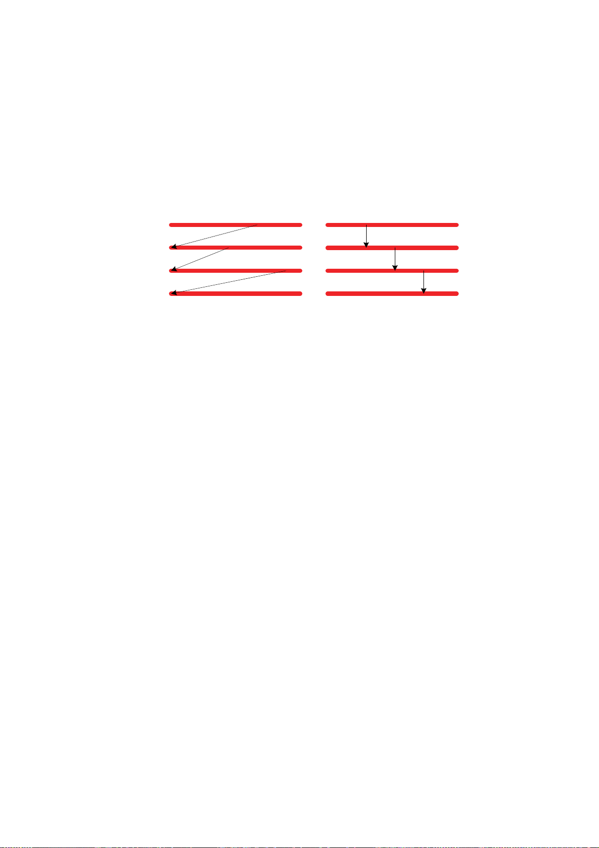
SynchronizedandNon‐SynchronizedModes
Channel A
Channel B
Channel C
Channel D
B
C
D
B
C
D
Non-
Synchronized
Synchronized
IN
IN
IN
IN
IN
IN
IN
IN
By default, the system works in non-synchronized mode; when you change camera
angles, replay is always re-cued from the marked In-point.
However, you can choose to work in synchronized mode; this causes replay to
continue from the same time stamp when switching channels.
To switch between non-synchronized and synchronized modes:
■ Press SHIFT, D.
The input buttons blink as long as the system is in synchronized mode.
3.Replay
Synchronized and Non-Synchronized Modes |
55
Page 56
Output
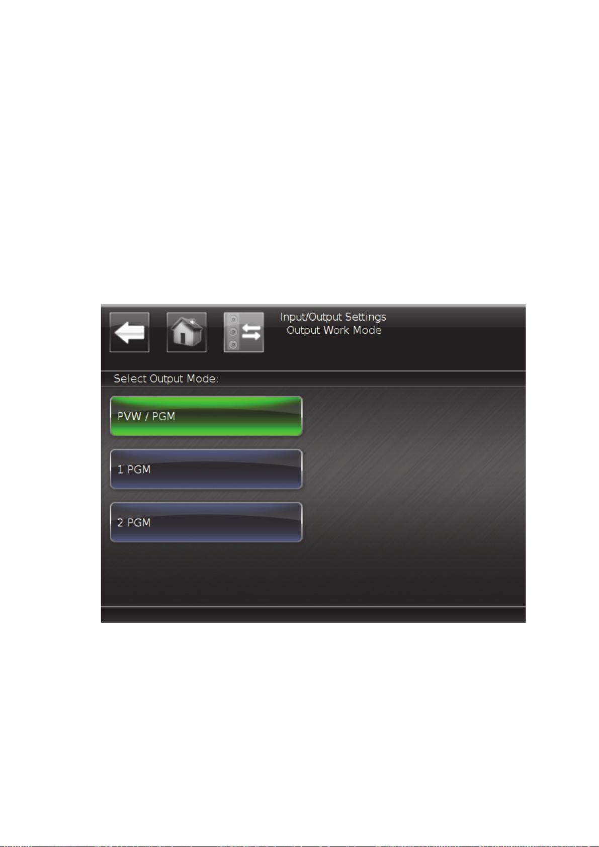
If more than one output is defined, PlayMaker provides two work modes, multi PGM or
PGM/PVW.
ConfiguringYourOutput
When working with two outputs, you must configure which output to use for PVW or for
the second PGM channel.
To configure the outputs:
1. In the Main screen, tap In/Out.
The In/Out options are displayed.
2. Tap Output Work Mode.
The available output mode options are displayed.
3.Replay
• Tap PVW/PGM to set one output as PVW, and one output as PGM.
• 1 PGM - relevant only when working with a single output configuration.
56
Output |
Page 57
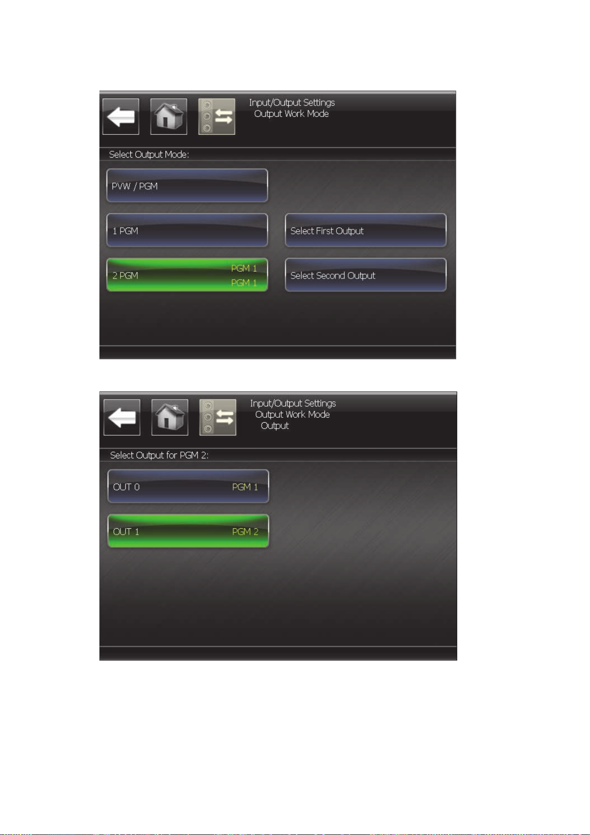
• 2 PGM - map the outputs as required.
Tap Select Primary Output to display the output options, and set as required.
3.Replay
Output |
57
Page 58

WorkinginPGM/PVWMode
In PGM/PVW mode, replay clips in the PGM output, while preparing the next item in the
PVW channel, and then switch between the outputs as required. This sends the item in
the PGM channel to the PVW channel, and the item that you prepared in the PVW
channel to the PGM channel. Use any available transition effect for this purpose.
By default, you work in the PGM channel. All controller actions affect the PGM output.
To work in the PVW channel:
■ Press PVW.
The PVW key flashes red (until you return to the PGM channel).
To return to the PGM channel, press PVW again.
When PVW is enabled, the LIVE key affects only the PVW channel. Cues, clips, and
playlists are loaded only to the PVW channel.
The Jog controls the PVW channel, however, the T-bar still controls the PGM channel
output.
Workingin2PGMMode
3.Replay
2 PGM mode provides two separate, independent outputs. In this mode, you can use
two controllers for the same server, if required. The the PVW key toggles control
between PGM1 and PGM2. The PVW key flashes red, as long as the control is on PGM2.
Although the outputs are independent, both outputs can use the same inputs, in Live
mode, or load clips created on PGM1 to PGM2.
Working with two Controllers, offers a number of possibilities:
• Set each Controller to have control of a single output.
• Set each Controller to control both outputs (with the same primary and secondary
settings).
• Set each Controller to control both outputs with different primary and secondary
outputs, so that each Controller acts as a backup Controller for the other (with
opposite primary and secondary settings).
58
Output |
Page 59

SettingupMultipleControllers
The communication protocol allows you to connect several Controllers to one Server,
and to set each Controller to handle specific outputs, or to set several Controllers to
control the same output.
All devices must be connected to one network, using a standard 1GigaBit Ethernet
hub.
In order to work with several Controllers, each controller must have a unique
Controller ID (See Network on page 30).
To set the output configuration:
1. Set the Control mode (see page 30) to 1PGM or 2PGM as required. (The number of
outputs controlled by the Controller).
When 1PGM is selected, tap Select First Output, and set the server output to
assign to the Controller PGM1.
When 2PGM is selected, you can set both server outputs to their required PGM
channels.
NOTE:
Several Controllers can control the same Server output, but any action made by
one Controller overrides any action made by other Controllers.
3.Replay
Setting up Multiple Controllers |
59
Page 60

3.Replay
60
Setting up Multiple Controllers |
Page 61

4.Cues
A cue is a point on the video that the system can return to when required, as long as the
recording is still available. PlayMaker can store up to 999 cues; if more than 999 cues are
marked, the latest cues overwrite the first cues in the list.
Inthissection:
Marking Cues on page 62
Cue Setup on page 62
Cue Sorting on page 64
Loading a Cue on page 64
Page 62
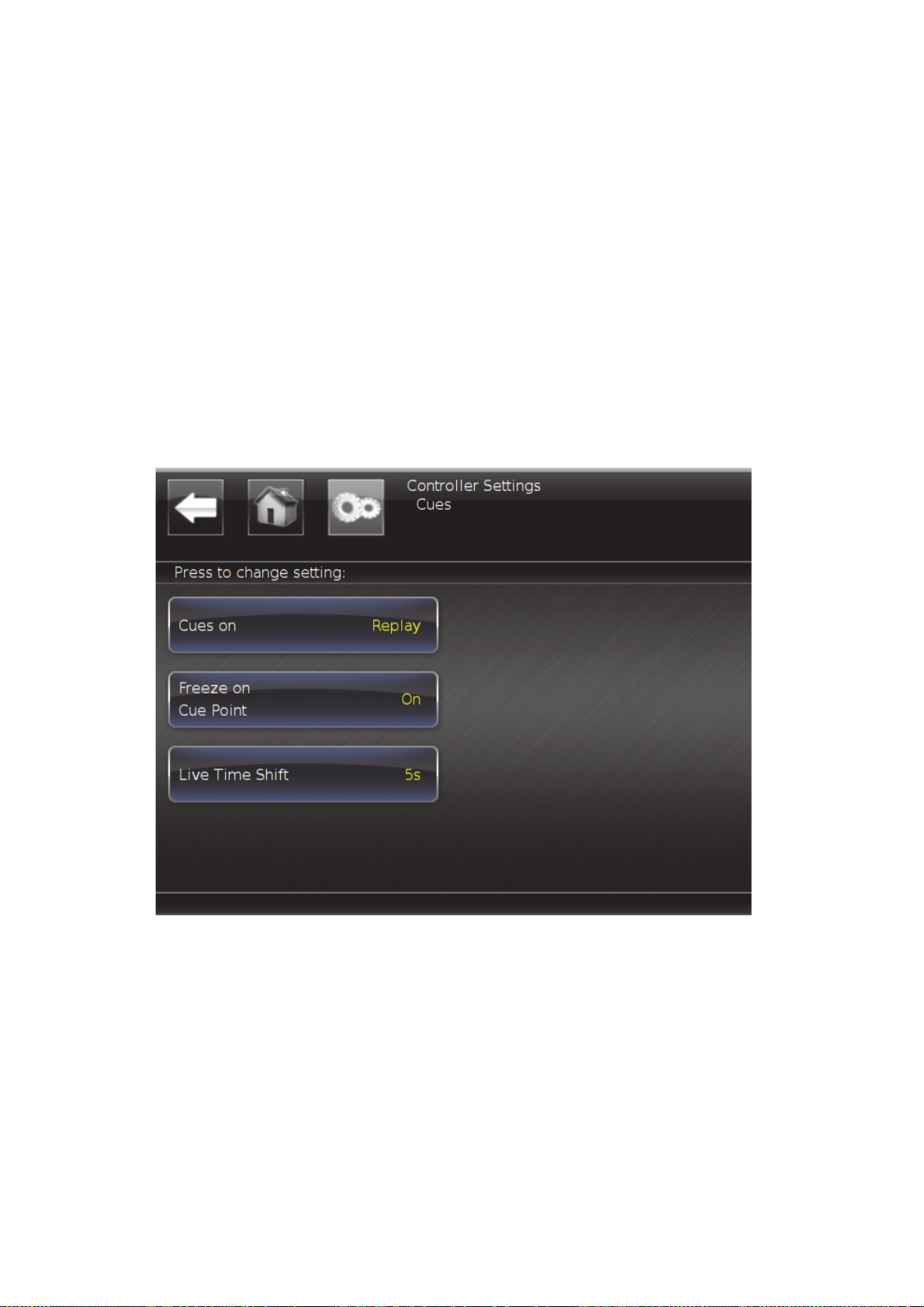
MarkingCues
To add a cue point:
■ Press CUE.
The cue point is set.
CueSetup
During setup, define different preferences for cues.
To access cue settings:
1. Press SHIFT, MENU to display the main screen.
2. Tap Controller to display the Controller settings.
3. Tap Cues to display the Cue settings.
4.Cues
62
Marking Cues |
Page 63
The following options are available:
Cues on Toggle to set if cues are set on the live input timecode (Live), or the
actual output position (Replay).
Freeze on
Cue Point
Live
Timeshift
Toggle (On) to set the replay to stop when a cue point is reached.
Use the T-Bar to play from cue. When set to Off, replay continues
when a cue is reached.
NOTE:
This feature is useful for offside replay in football games. Set
the cue on the offside frame, roll back and start replay.
Playmaker will automatically stop on the exact frame of the
offside.
When cues are set on the live input, open a slider to define the
pre-roll time shift. The time shift can be set between 0 to 5 seconds,
in one-second intervals. This feature allows you to compensate for
the time between recognizing the action and the pressing CUE.
For example, if the time shift is 2 seconds (and Cues on is set to
Live), and a cue is placed on timecode 08:12:47:12, then when
recalled, it will load 08:12:45:12.
4.Cues
Cue Setup |
63
Page 64

CueSorting
Cues are assigned three-digit numbers that do not reflect the timecode, just the order
in which they were set.
Cue numbers are displayed with the OSD data. (See OSD Data for Live/Replay on
page 48) Generally, in live or replay, the last created cue number is displayed. When
jumping between cues, the currently displayed cue is displayed.
LoadingaCue
To load a cue:
■ Use one of the following keys:
PREV - loads the latest cue set in the game (that is, the cue with the most advanced
timecode, not the last cue created).
NEXT - loads the next cue in the game. If you are at the last cue in the game, NEXT
jumps to the first cue.
4.Cues
64
Cue Sorting |
Page 65

Inthissection:
About Clips on page 66
Creating a Clip on page 67
Playing a Clip on page 76
Clip Setup on page 79
5.Clips
Page 66

AboutClips
A PlayMaker clip is a recorded portion of a game for which you determine the start (In)
and end (Out) points, number, name, and tag, in either the live display or the
playback. By default, a clip is saved with a few seconds added before its start point and
after its end point (safety zone).
ClipNumbering
The clip number is a unique identifier comprised of a three-digit number and a letter
(A/B/C/D/E/F) indicating the input channel on which the clip was created.
If more than one input is recorded, each clip is saved for all recorded inputs. The input
for which the clip’s Out-point was defined is the master input. Other clips are derived
from the master clip’s in and out points. The derived clips use the same clip numbers,
with different input indicators. The system can save up to 1000 master clips and 7000
derived clips. In- and Out-points of the derived clips can be changed later, within the
safety zone limit.
PlayMaker gives you the option of creating clips that are numbered automatically,
using the first available number slot, or lets you assign a clip number manually.
ClipNaming
5.Clips
Each clip can be given an alpha-numeric name for easy identification, that always
appears with the clip number, in the list of clips, if a name is assigned. The maximum
number of characters in a clip name is 31.
ClipTags
You can set an SmartEvent tag or label for a clip. For example, for a soccer game, set
a “goal” tag. Applying a tag makes it easier to access other clips with the same tag.
When creating a clip, these tags are displayed on the LCD keys.
If a clip has only a number assigned, and is unnamed, the tag is displayed in the list of
clips, with the clip number.
66
About Clips |
Page 67
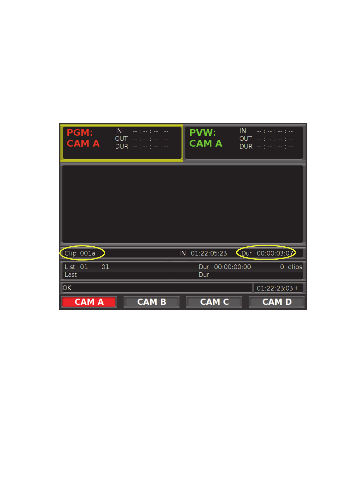
CreatingaClip
To create a clip with the default duration:
1. Press LIVE to reset all operations.
2. Press IN or OUT to set the start or end frame of the clip.
3. Press ENTER.
The clip is created with an auto number, and the default duration set in Clips on
page 30.
5.Clips
Creating a Clip |
67
Page 68
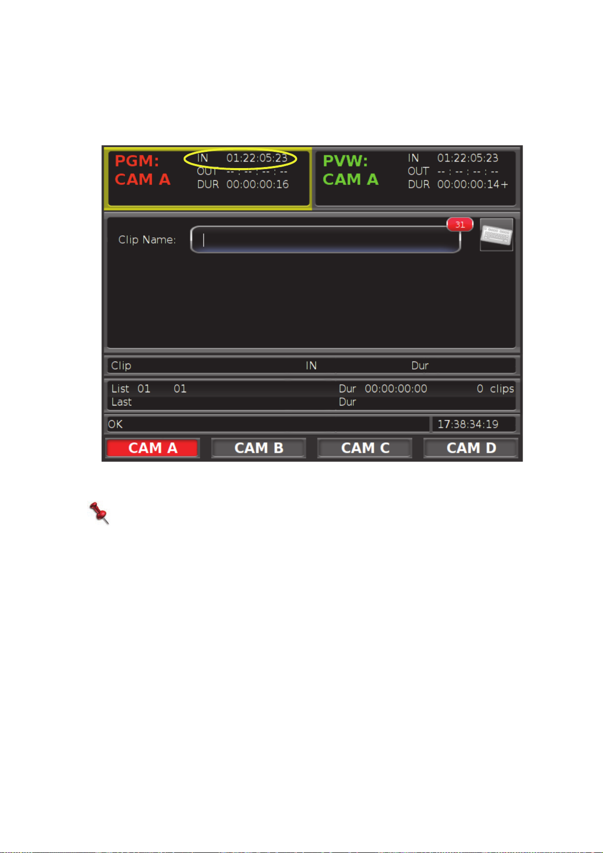
To create an auto numbered clip with In and Out points:
1. Press LIVE to reset all operations.
2. Use the Jog to roll to the required spot.
3. Press IN to set the starting frame of the clip.
5.Clips
4. If required, assign a name for the clip. (Tap the keyboard icon to open a virtual
keyboard).
NOTE:
This can be done at any point, before the clip is saved.
5. Use the Jog to roll to the required spot.
68
Creating a Clip |
Page 69
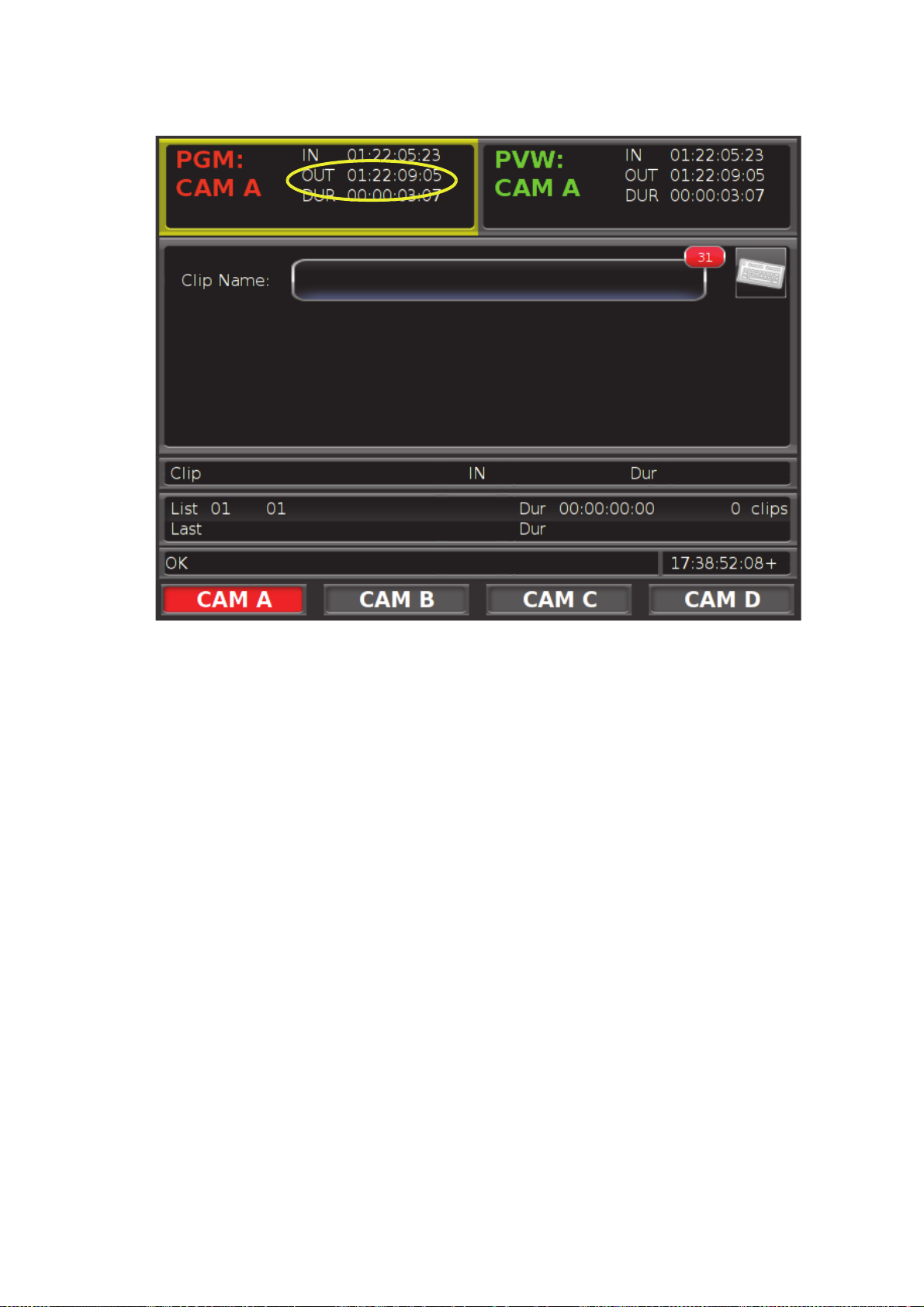
6. Press OUT to set the end frame of the clip.
7. Press ENTER.
The clip is created with automatic numbering, using the first available number slot.
For example, clip 001A is the first clip with auto-numbering saved by the system.
The “A” specifies that the clip was marked for input A, and this will be the input that
is cued and played when you load the clip.
PlayMaker allows the following options when setting a clip:
• Set the Out point before rolling back and setting the In point.
• If you only set one point, the system uses the default duration setting to create a
clip. (See Clips on page 30.)
To set a number for a clip:
1. Execute steps 1-6, above.
2. Type in a three-digit number using the numeric keypad.
For information on using the numeric keypad, see Using the Numeric Keypad on
page 80.
3. Press ENTER.
5.Clips
Creating a Clip |
69
Page 70
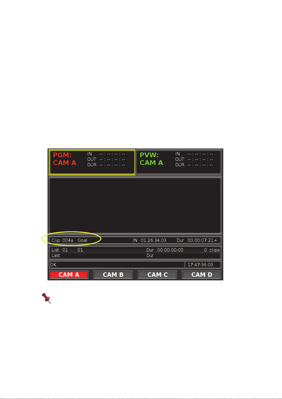
To set a SmartEvent for the clip:
1. Execute steps 1-6, above.
If required, set the clip number manually, but do not press ENTER.
2. When working in LCD key single event mode, press an LCD key to select the
SmartEvent.
The clip is marked.
Or-
When working in touchscreen multi-event mode or in touchscreen single-event
mode, tap the appropriate LCD key to open the SmartEvent page.
To set the active SmartEvent group (whose pages are displayed), see Groups,
Pages, and SmartEvents on page 35.
3. Tap to select the required SmartEvent (or SmartEvents when working in multi-event
mode).
4. Press ENTER.
The clip is numbered, marked, and saved.
5.Clips
For more information on defining SmartEvents, see SmartEvents on page 34.
NOTE:
If you tap a touchscreen SmartEvent that has already been selected, it is
displayed with a red background. All subsequently created clips will be tagged
with this SmartEvent, until you clear the SmartEvent (by tapping it).
To save a clip directly to a playlist:
1. Execute steps 1-6, above.
2. Press STORE
The clip is stored in the current playlist.
70
Creating a Clip |
Page 71
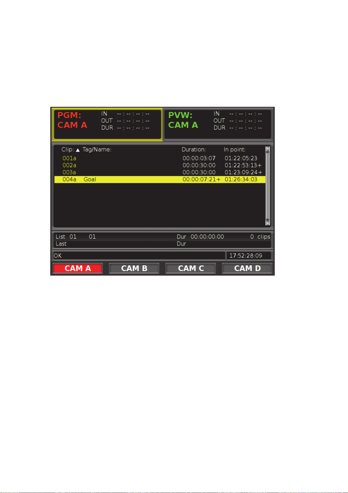
ListofClips
From the list of clips you can perform a number of actions.
To open the list of clips:
1. Press LIVE to reset all operations.
2. Press MENU.
Once the list of clips is displayed, choose a clip to load (see Loading a Clip on page 73),
or sort the list by SmartEvent.
Each row in the list represents a clip. Each column displays clip data, and each color of
the clip number indicates various states as follows:
Clip - clip number. Tap the column heading to sort the list by clip number.
Tag/Name - the name or SmartEvent assigned to the clip. Tap the column heading to
sort the list by names or events.
Duration - clip duration
In-point - the time stamp of the clips In-point.
Yellow clip number- normal.
5.Clips
Blue clip number - the clip is used in a playlist.
Red clip number - the clip is locked (cannot be deleted).
Purple clip number - the clip is both locked and used in a playlist.
Creating a Clip |
71
Page 72

SortingClipsbySmartEvent
When a list of clips is open, the LCD keys show available pages. The selected page is
red and available SmartEvents are displayed on the touchscreen. Only SmartEvents
which are already assigned to clips will be available. Select a SmartEvent to display the
clips tagged with the SmartEvent. You can select additional pages and SmartEvents to
filter the list further.
5.Clips
72
Creating a Clip |
Page 73

LoadingaClip
To load the last created clip:
■ Press SHIFT, CLIP.
The clip is loaded.
There are two ways to load any clip for playing; from the numeric keypad, or from the
list of clips.
To load a clip with a known number from the numeric keypad:
1. Press LIVE to reset all operations.
2. Enter the clip number in the numeric keypad.
For more information, see Using the Numeric Keypad on page 80.
3. Press ENTER.
The clip is loaded at its first frame.
To load a clip from the list of clips:
1. Open the list of clips. See List of Clips on page 71.
2. Using the Jog, or the PREV or NEXT keys to select a clip from the list of clips.
3. Press ENTER.
The clip is loaded at its first frame.
5.Clips
Once a clip is loaded, the functions of the LCD keys change, together with the text
displayed on the keys.
The following functions are available when a clip is loaded:
(ABC)
RENAME
SET
SMARTEVENT
Send to Copy the current clip to a remote server or a shared directory.
DELETE Delete the current clip. (The key is red if the clip is protected).
< PREV Load the previous clip.
> NEXT Load the next clip.
Press SHIFT to access additional options
LOOP Set the current clip to play in a loop. See Looping Clips on page 77.
PLAY ALL Set all clips to be played, starting with the first clip. See Playing All
Open a virtual keyboard or use an external keyboard to name or
rename the current clip.
Switch LCD keys to available SmartEvents to select a SmartEvent tag
for the current clip. You can replace the current clip tag or set a new
one.
For more information, see Copying Clips from Local Server to Remote
Server on page 97 and Copying Clips to a Shared Directory or
External Device on page 97.
Clips on page 76.
Creating a Clip |
73
Page 74
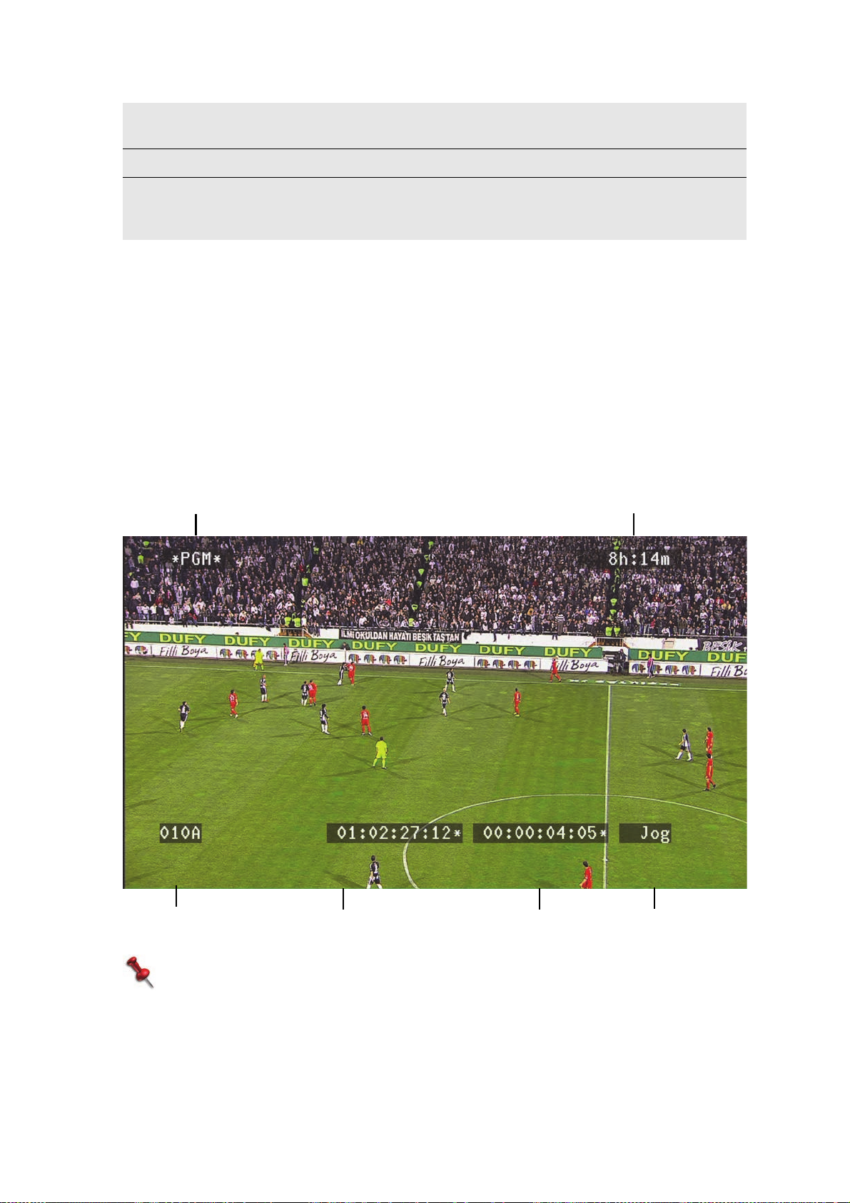
SET
Output
Channel - asterisks indicate the active channel
Remaining
Recording Time
Clip and Input Current Timestamp Time to End of Clip
Control
MASTER
LOCK Protect the clip from deletion. See Protecting a Clip on page 78.
COPY Copy the current clip with a different clip number and/or tag to the
While a clip is loaded (even after it has been played), you can jump to its In- or
Out-point quickly.
Set the default input for displaying the current clip. (Select the input
key, and press SET MASTER.)
next available slot. (Press ENTER to save the clip or type a three digit
number and press ENTER.)
To jump to the In/Out point:
■ P r e s s S H I F T, > I N o r S H I F T, > O U T, a s r e q u i r e d .
OSDDataforaLoadedClip
When a clip is loaded, if OSD data is set to be displayed, the following data appears in
the OSD.
5.Clips
NOTE:
The Control data shows the video speed 1-10000(%), if the video is playing.
If the replay is stopped using the Jog, “Jog” is displayed.
74
Creating a Clip |
Page 75

ChangingClips
After creating a clip, you might want to change the In/Out points of the clip or of one of
the derived clips within the limits of the clip and safety zone. (Derived clips can have
different In- and Out-points.)
To change In/Out point:
1. Load your clip (see Loading a Clip on page 73).
You can change the In/Out points of a clip, if required. Use the Recording Channel
(A/B/C/D) keys to select the angle.
2. Roll to the required In- or Out-point, and press IN or OUT, as required.
For more information, see Creating a Clip on page 67.
To set an In-point prior to the existing In-point:
1. Load your clip (see Loading a Clip on page 73).
2. Press CLR.
The key turns red.
3. Press ENTER.
The existing In-point is deleted.
4. Roll to the required In-point.
5. Press IN.
The new In-point is set.
To set an Out point prior to existing Out-point:
1. Load your clip (see Loading a Clip on page 73).
2. Press CLR.
The key turns red.
3. Press ENTER.
The existing Out-point is deleted.
4. Roll to the required Out-point.
5. Press OUT.
The new Out-point is set.
NOTE:
Previously set In/Out points need to be cleared if the required change involves
marking an In-point that is later than the original Out-poin t, or marking an
Out-point that is earlier than the original In-point.
5.Clips
Creating a Clip |
75
Page 76

PlayingaClip
To play a loaded clip:
■ Press PLAY, or use the T-Bar to play the clip at the required speed. (You can also use
the Jog for a frame-by-frame display.)
If you want to review the clips in the list visually, press the PREV or NEXT LCD key
to load the previous or next clip.
When a clip is loaded, you can only view the loaded clip, and its set safety zone.
However, you can switch from the clip, back to the recording at the same time stamp,
as follows:
To return to the recorded footage (at the same time stamp):
■ Press SHIFT, LIVE.
The clip is unloaded; view any part of your recording.
PlayingAllClips
Play all master and derived clips starting with the first clip. This allows you to play all
clips sequentially for backup, melt (play to VTR), export or any other purpose.
5.Clips
To play all clips in the list of clips:
1. Load any clip (see Loading a Clip on page 73).
The LCD keys display options relevant for clips.
2. Press PLAY ALL. Play begins immediately.
A message is displayed while clips are playing, and all keyboard keys, Jog, and
T-Bar are disabled.
To exit this mode, press SHIFT, LIVE.
76
Playing a Clip |
Page 77
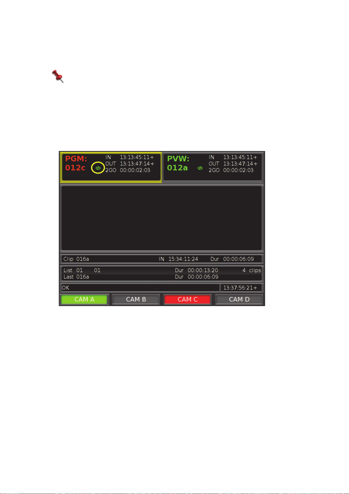
LoopingClips
You can set the current clip to play in a loop.
NOTE:
This setting remains activated for the clip, each time the clip is loaded, until
cancelled.
To set a clip to be played in a loop:
1. Load the clip to be looped (see Loading a Clip on page 73).
The LCD keys display options relevant for clips.
2. Press SHIFT, LOOP.
A Loop indication is displayed with the clip info.
To cancel, press SHIFT, LOOP (while clip is loaded).
5.Clips
Playing a Clip |
77
Page 78
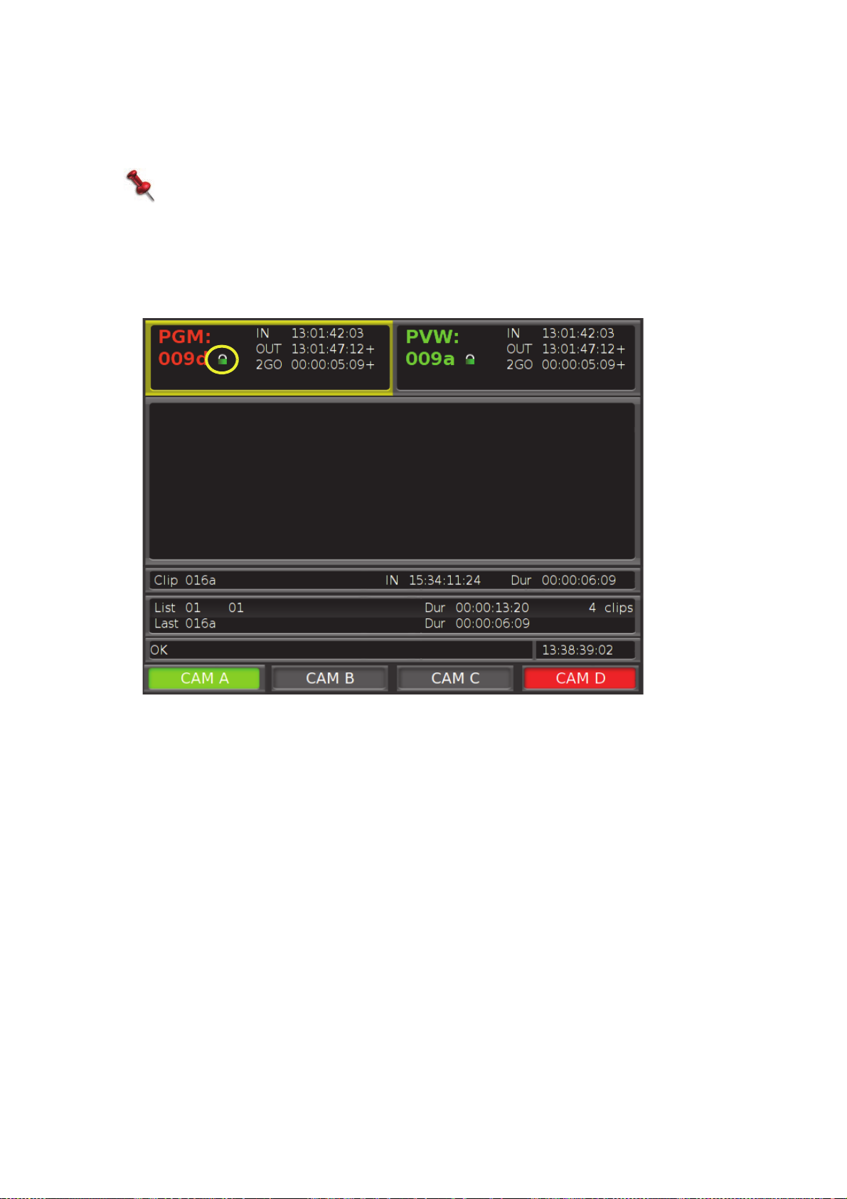
ProtectingaClip
When a clip is loaded, lock it to prevent it from being deleted, if required.
NOTE:
If the recording is deleted, or if the clean disk option is used, protected clips are
deleted, as well.
To lock a clip:
■ Press SHIFT, LOCK.
A lock indication is displayed with the clip info. DELETE is disabled.
5.Clips
78
Playing a Clip |
Page 79
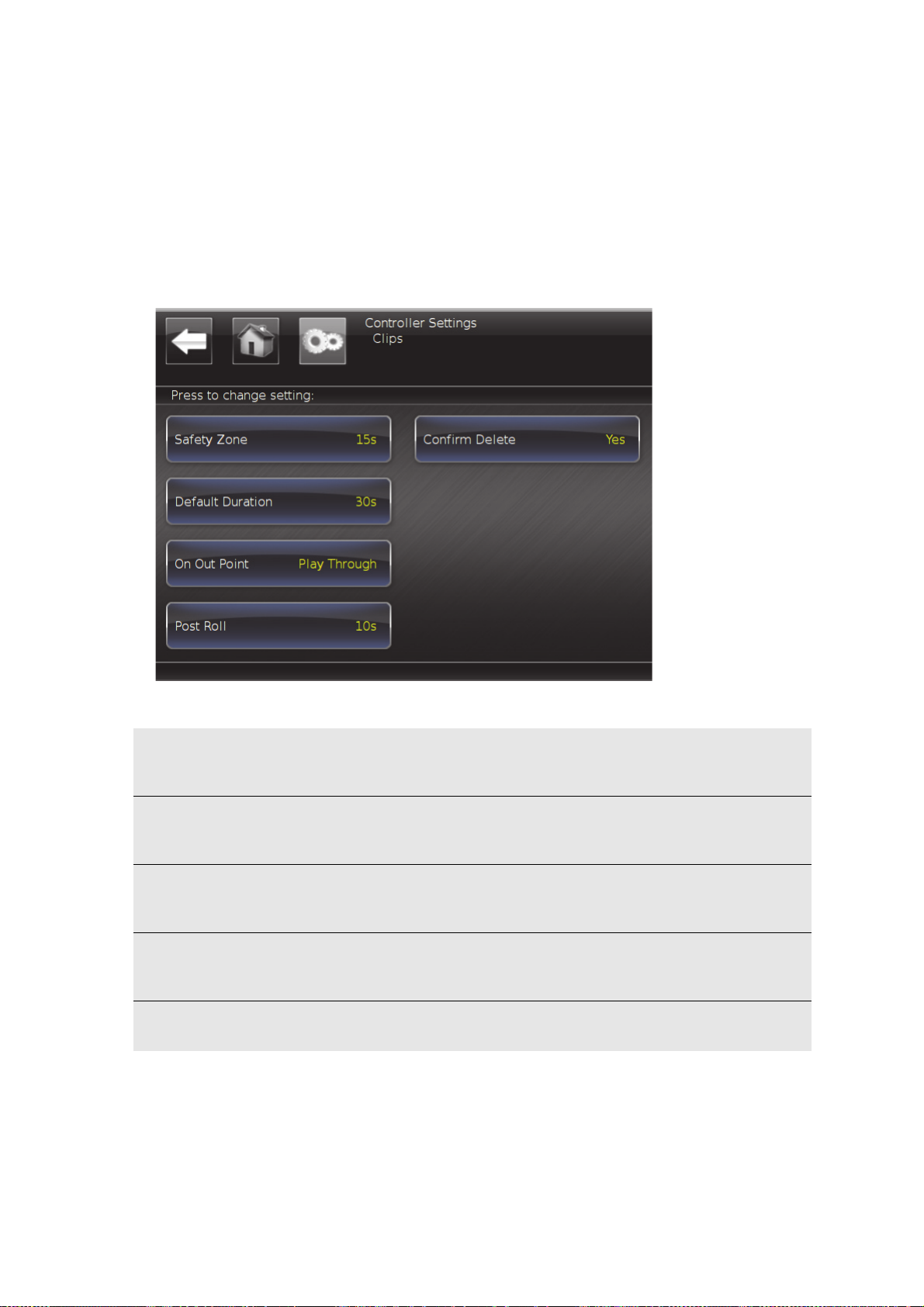
ClipSetup
During setup, you can define different preferences for clips.
To access clip settings:
1. Press SHIFT, MENU to display the main screen.
2. Tap Controller to display the Controller settings.
3. Tap Clips to display the clip settings.
The following options are available:
Safety
Zone
Default
duration
On
Out-point
Post Roll Open a slider to set for how many seconds the clip will continue
Confirm
Delete
Open a slider to set the number of seconds saved with the clip before
the in-point and after the out-point of the clip. Default time: 10
seconds. (Possible range is 1-59 seconds.)
Open a slider to set the default duration of a clip (used if only the Inor Out-point is marked). Default time: 5 seconds. (Possible range is 1
second - 24 hours.)
Toggle to set clip behavior when it reaches the out-point; either it will
stop playing (Freeze), or play until the post roll point (Play
Through). Default is Freeze.
playing after the out-point (relevant only if the "on out point"
parameter is set to "play through"). Default time: 5 seconds.
Toggle Yes to require confirmation before a clip is deleted (default) or
No to allow instant deletion of clips.
5.Clips
Clip Setup |
79
Page 80

UsingtheNumericKeypad
The main function of the numeric keypad is for manually numbering and loading clips.
When numbering or loading, the key colors change to indicate available number slots
or existing clips.
Upon first use, when creating a clip, all keys are green, to indicate their availability.
Once clip 001 (for example) exists, the 1 key will turn orange after you type in “00” to
indicate that slot 001 is assigned. As the clip number slots fill up, you will see more
keys turn orange when typing in clip numbers.
For example, if you have 99 clips stored (with sequential numbering), the next time
you add a clip, the 0 key will be orange, indicating that all new clips must start with a
different digit.
When loading a clip, the opposite logic applies; the green keys indicate assigned clip
number options. If you have 99 clips stored (with sequential numbering), only the 0
key will be green as the first digit.
5.Clips
80
Clip Setup |
Page 81

6.Playlists
Playlists are used to group clips for playing later as a sequence. The same clips can be
added to multiple playlists.
PlayMaker allows you to create up to 99 playlists. By default, the active playlist is List 01.
When adding a clip to a playlist, it is always added to the active playlist.
When you add a clip to a playlist, the clip in and out points are copied to the playlist in
order to create a derived clip. The derived clip can be edited within a playlist to change it’s
In- and Out-points (without affecting the original clip) within the limits of the clip duration
and safety zone.
Clips in a playlist are locked, and cannot be deleted unless removed from the playlist.
Inthissection:
Setting the Active Playlist on page 82
Loading the Current Playlist on page 84
Adding Clips to the Playlist on page 85
Changing Clips Within a Playlist on page 88
Playlist Setup on page 92
Page 82
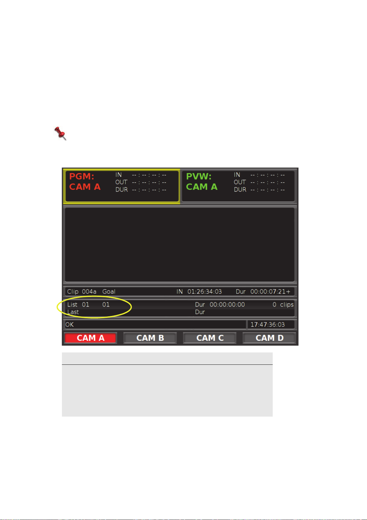
SettingtheActivePlaylist
To set a playlist as the active playlist:
1. Press LIVE to reset.
2. Press LIST.
LST is displayed in the Seven-Digit display.
3. Using the Numeric keypad, enter the number of the playlist that you want to make
active. For more information, see Using the Numeric Keypad on page 80.
NOTE:
If you enter a playlist number that does not exist, a new playlist is created.
4. Press ENTER.
The selected playlist is now the active playlist, as indicated in the Playlist Line.
6.Playlists
Parameters displayed in the Playlist line:
•Playlist number
• Duration of playlist
• Number of clips in playlist
• Last clip added to the playlist
• Duration of last clip
82
Setting the Active Playlist |
Page 83

To select a playlist from the list of playlists:
1. Press MENU twice.
A list of all populated playlists are displayed.
2. Use the Jog, or the PREV or NEXT keys, to select the required playlist.
3. Press ENTER to make the selected playlist active.
6.Playlists
Setting the Active Playlist |
83
Page 84
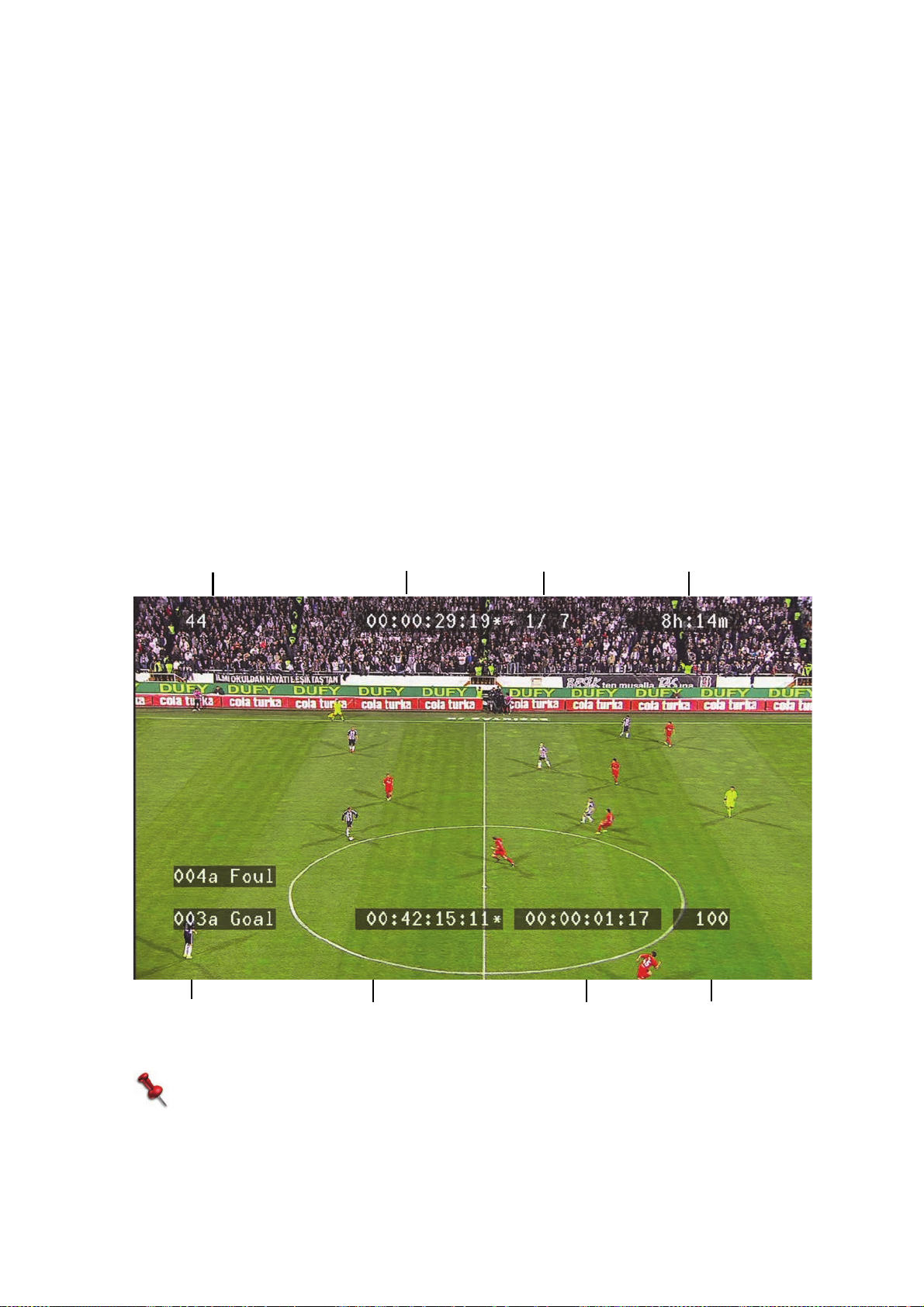
LoadingtheCurrentPlaylist
List
Number
Remaining
Recording Time
Clip # and SmartEvent
Current Timestamp
Time to End of Clip
Control
Time to End of Playlist Playing clip 1 of 7
(Upper - next clip
Lower - current clip)
To load the active playlist:
■ Press LIST three times to open the active playlist.
The playlist opens with the first clip in the playlist selected.
To play the clips in the list, press PLAY or use the T-Bar to play at the required
speed, or the Jog dial for field-by-field.
If you want to load the playlist from the last position, press LIST twice. When the
playlist is loaded, the LCD keys change to display options relevant to the playlist.
To browse the playlist:
■ After loading the playlist, press BROWSE.
Use the Jog to display the first frame of any clip in the list. (Press BROWSE again to
cancel the browsing function and use the Jog to play frame-by-frame.)
OSDDataforaPlaylist
When a playlist is loaded, if OSD data is set to be displayed, the following data appears
in the OSD.
6.Playlists
NOTE:
The Control data shows the video speed 1-10000(%), if the video is playing. If
the replay is stopped using th e Jog, “Jog” is displayed.
84
Loading the Current Playlist |
Page 85

AddingClipstothePlaylist
Clips can be added to the end of the playlist or inserted at any point in the playlist.
To append a clip to a playlist:
1. Press LIVE to reset.
2. Load the clip (see Loading a Clip on page 73).
3. Press STORE to add the clip to the end of the playlist.
A playlist icon is displayed with the clip.
To insert a loaded clip in a playlist:
1. Press LIVE to reset.
2. Press LIST twice to open the required playlist.
3. Press BROWSE, and select a clip.
4. Press MENU to open the list of clips.
5. Load the required clip (see Loading the Current Playlist on page 84).
6. Press SHIFT, INSERT.
The list of clips is displayed. The clip is added to the playlist before the currently
selected clip.
Once a clip is loaded, you can select an additional clip angle (camera) that you want
to add to the playlist.
6.Playlists
To add another clip angle to the playlist:
1. Load the clip (see Loading a Clip on page 73).
2. Select the first camera, using the Recording Channel (A/B/C/D) keys.
3. Press STORE.
4. Select the second camera, using the Recording Channel (A/B/C/D) keys.
5. Press STORE.
To delete a clip from a playlist:
1. Open the required playlist.
2. Select the required clip using the Jog.
3. Press the DELETE (CLIP).
Adding Clips to the Playlist |
85
Page 86
To add clips from a different playlist to the current playlist:
1. Open the playlist to which you want to add on to.
2. Use the Jog to select the insert position.
3. Press SHIFT, ADD LIST.
All populated playlists are displayed.
4. Use the Jog to select the playlist to add.
5. Press ENTER.
The clips from the selected playlist are appended.
NOTE:
Try this: load your first clip, sto re it, and then use the next/prev LCD keys to
quickly run through all clips by number. Press STORE for each clip you want to
add to the playlist.
ReorganizingthePlaylist
Once all required clips are in the playlist, you can change the order of the clips.
To reorder clips in the playlist:
1. In the Playlist, select the clip you want to move.
2. Press DELETE.
3. Using the Jog, highlight the new position.
6.Playlists
4. Press SHIFT, INSERT to paste the last deleted clip.
NOTE:
The last deleted clip is stored in memory only until another clip is deleted, or you
close the playlist screen.
AddingClipswithSmartEventtoaPlaylist
For quick playlist creation you can add all clips with an assigned SmartEvent to the
current playlist.
To add clips:
1. Press MENU to open the list of clips.
2. Using the LCD keys, select a SmartEvent whose clips you want in the playlist.
Only clips with the selected SmartEvent are displayed.
3. Press SHIFT, STORE.
All clips of the selected SmartEvent are added to the current playlist.
AddingClipstoMultiplePlaylists
86
When Multiple Playlist is ON, you can add a clip to all active playlists in one action.
Playlists must be assigned to the LCD keys for selection.
To turn Multiple Playlist ON, see Multiple Playlist on page 93.
Adding Clips to the Playlist |
Page 87

To assign a playlist to an LCD key:
1. Press LIVE.
2. Press MENU twice to open the list of Playlists.
Assigned playlists show on the LCD keys, as Playlist name and Number. If no
playlist is assigned to an LCD key, it will read ASSIGN PL.
3. Select the required playlist by using the Jog or PREV/NEXT.
4. Press any of the unassigned LCD keys to assign the selected playlist to the key.
5. Type in the list number.
To clear a playlist from an LCD key:
1. Press LIVE.
2. Press MENU twice to open the list of Playlists.
3. Press CLR.
The Key flashes.
4. Press the LCD key that you want to clear.
Note:
Detaching a playlist from an LCD key does not delete the playlist, it will still be
available with all its content.
To add an existing clip to multiple playlists:
1. Load the clip to the active output.
2. Press STORE.
All assigned playlists are displayed on their LCD keys.
3. Select one or more playlists.
The selected keys turn red. (Press the key again to clear it.)
4. Press STORE to confirm.
The clip is added to all selected playlists.
To add new in and out points to playlist (during clip creation):
1. Press LIVE.
2. Set in- and out-points.
3. Press STORE.
All assigned playlists are displayed on their LCD keys.
4. Select one or more playlists.
The selected keys turn red. (Press the key again to clear it.)
5. Press STORE to confirm.
The clip is created and added to all selected playlists.
6.Playlists
Note:
When adding a second clip, the last selected playlists are selected on the LCD
keys (shown in red). You can either press STORE, to save the clip to those
playlists, or select and clear playlists as required, and then press STORE.
Adding Clips to the Playlist |
87
Page 88

ChangingClipsWithinaPlaylist
To change a clip’s In/Out points within a playlist:
1. Select the required clip in the playlist.
For more information, see To browse the playlist: on page 84.
2. Press IN or OUT to mark new points, as required, within the clip limits (not including
the safety zone).
3. If you need to set In- and Out-points from the safety zone, press CLR, IN or CLR,
OUT as required.
The In- or Out-point is cleared, and the first frame in the safety zone becomes the
In-point or the last frame in the safety zone becomes the Out-point.
4. Roll to the required frame, and set the points.
For more information, see Creating a Clip on page 67 and Loading a Clip on
page 73.
PlayingaPlaylist
There are a number of options for playing a playlist.
To play a playlist by number:
6.Playlists
1. Press LIST.
2. Using the numeric keypad, enter the required playlist number.
3. Press ENTER. (This loads the playlist to the output at the first frame. If the server
was playing a recording, the new playlist starts playing, according to T-Bar position
or Play status.)
4. If required, press PLAY, or use the Jog or T-Bar to play the playlist.
To play the current playlist:
1. Press LIST three times to open the current playlist, and press PLAY or use the T-Bar
to play at the required speed.
To select a playlist from the list of playlists:
1. Press MENU twice.
All playlists are displayed.
2. Use the Jog dial to select a playlist.
3. Press ENTER to load the playlist. (This loads the playlist to the output at the first
frame. If the server was playing a recording, the new playlist starts playing,
according to T-Bar position or Play status.)
Or-
Press BROWSE to display the clips in the playlist without loading.
88
Changing Clips Within a Playlist |
Page 89
AdditionalOptions
When a playlist is open, and displays the derived clips it contains, the functions of the
LCD keys change, together with the text displayed on the keys.
The following functions are available when a playlist is open:
EDIT BACK - return to the main playlist LCD key options.
EFFECT DURATION - set the duration of the transition effect
between clips in the playlist. Range is 0-2 seconds at one-frame
intervals. For more information, see Transition Effects on page 90.
EDIT ALL - press EDIT ALL before making a change in the edit
options, to apply the change to all clips in the list.
SPEED - set the speed of clips when played from the playlist. For
more information, see Setting Clip Speed on page 91.
EFFECT - set the effect type when transitioning between clips in the
playlist. When you press EFFECT, the effect types are displayed on
the LCD keys. The selected effect key displays a blue background and
the effect will be applied on the Out point of the clip. For more
information, see Transition Effects on page 90. (The default effect is
set in the Playlist Setup on page 92.)
DELETE Delete the selected clip from the playlist.
NEXT Play the next clip in the playlist immediately.
SKIP Finish playing the currently playing clip, skip the next clip, and play
the following clip.
BROWSE Press Browse to use the Jog to select any clip in the playlist. The first
frame of the selected clip is displayed in the active output.
Press SHIFT to access additional options
LOOP LIST Set the playlist to play in a loop until you load another clip or playlist
or until you press LIVE. This setting remains activated for the playlist
until cancelled. Loop indication is displayed with the playlist name.
To cancel, press SHIFT, LOOP LIST.
ADD LIST Add a different playlist to the current playlist as a group of clips.
For more information, see To add clips from a different playlist to the
current playlist: on page 86.
6.Playlists
Changing Clips Within a Playlist |
89
Page 90
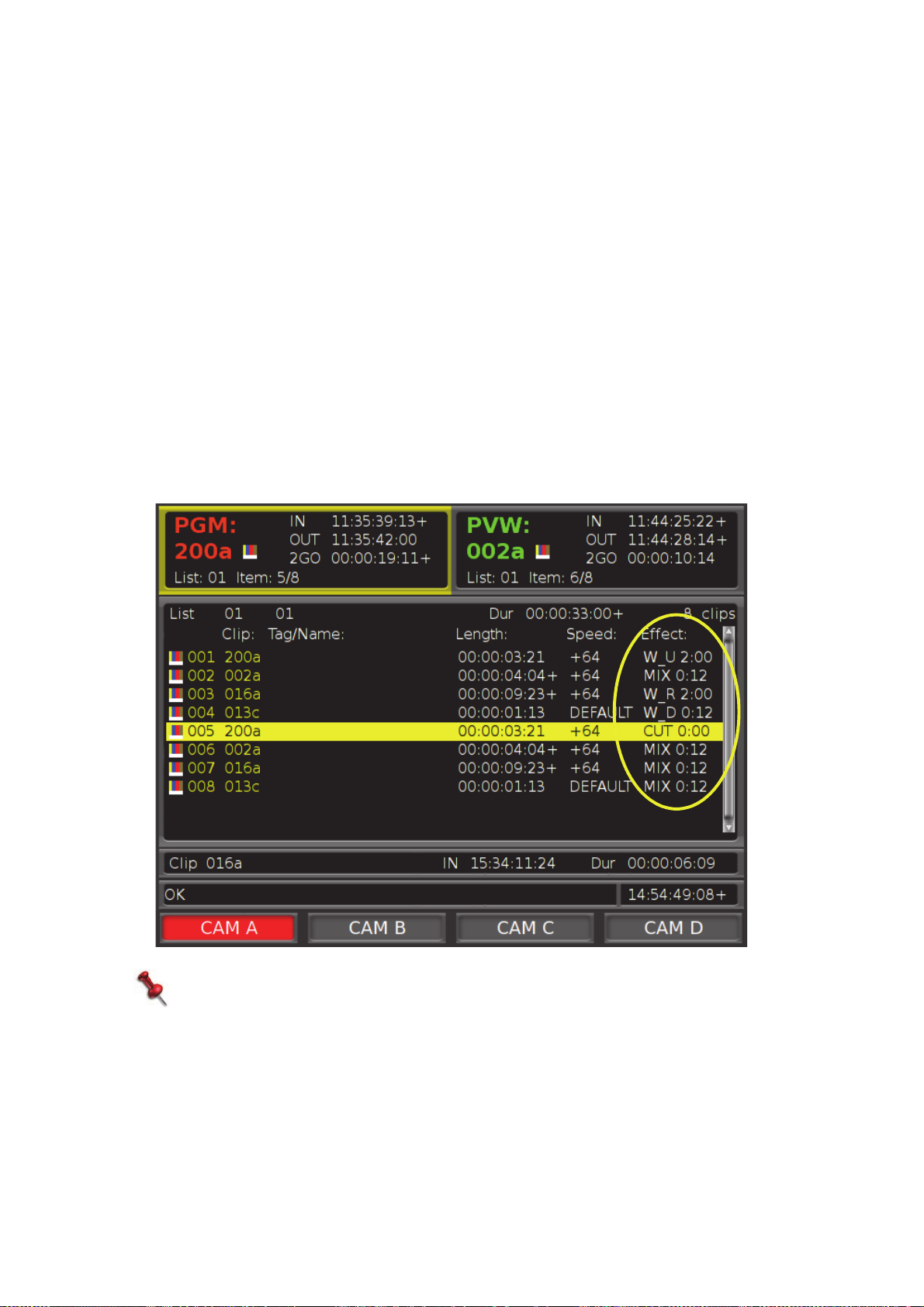
TransitionEffects
One of the advantages of playing clips from a playlist, is the option set the transition
effect between clips, and its duration. Set an effect for all clips in the playlist, or set an
effect for each clip.
To set the transition effect:
1. Open a playlist.
The LCD buttons display the EDIT function.
2. Press EDIT.
The LCD keys change, displaying the editing functions on the keys.
3. Press the EFFECT.
The LCD keys change, displaying the available effects; CUT, MIX, WIPE UP, WIPE
LEFT, WIPE RIGHT, WIPE DOWN.
4. Press a key to select the required effect.
The effect is set for the selected clip, and indicated in the Effect column.
6.Playlists
NOTE:
This is the workflow for each clip; to change all clips at once, use EDIT ALL.
90
Changing Clips Within a Playlist |
Page 91
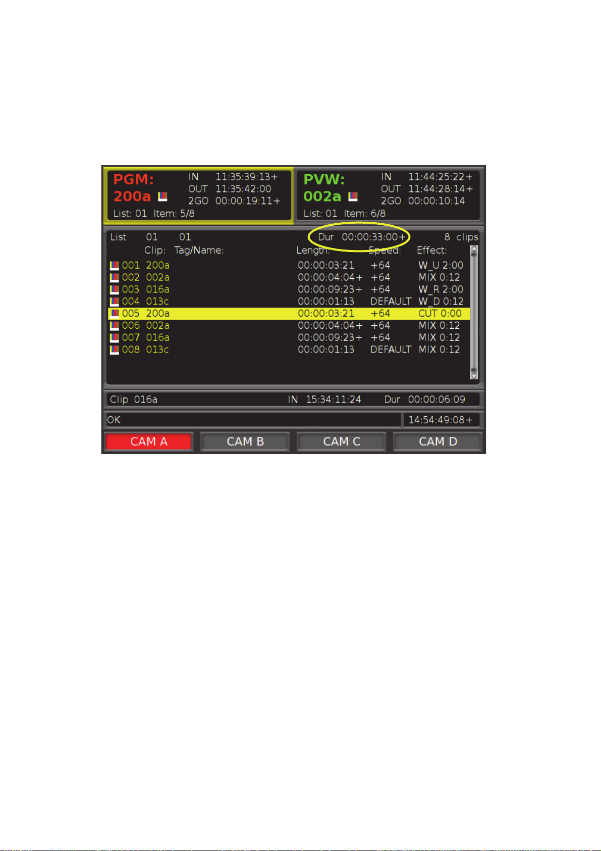
To set the transition effect duration:
1. With the playlist open, select EFFECT DURATION.
The LCD key turns blue.
2. Use the T-Bar to select the effect duration (0-2 seconds).
The duration is indicated in the list (Dur).
3. Press EFFECT DURATION to set the duration.
SettingClipSpeed
Set the speed at which to play each clip in the playlist (or all clips, using EDIT ALL)
when played from the playlist. The speed you set here only affects clip speed when you
use the PLAY button to play the playlist, disregarding the default speed set for the
playlist. Use the Jog or T-Bar to manually control clip speed, even when you have
changed the default.
To set clip speed:
1. From the playlist, select the clip to change.
2. Press SPEED.
The LCD key background turns blue.
3. Adjust the speed using the T-Bar.
6.Playlists
The speed is indicated in the speed column in the playlist.
4. Press SPEED again.
Clip speed is set.
Changing Clips Within a Playlist |
91
Page 92
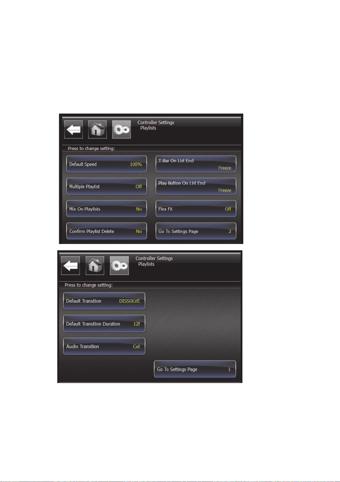
PlaylistSetup
During setup, you can define different preferences for playlists.
To access playlist settings:
1. Press SHIFT, MENU to display the main screen.
2. Tap Controller to display the Controller settings.
3. Tap Playlists to display the playlist settings.
6.Playlists
92
Playlist Setup |
Page 93
The following options are available:
Default
Speed
Multiple
Playlist
Mix On
Playlists
Confirm
Playlist
delete
T-Bar On
List End
Play
Button On
List End
Flex FX Not available in the current version.
Open a slider to set the default speed at which the clips in the playlist
are played when using the PLAY key. Default is 100%.
Turn on to enable multiple active playlists in order to add a clip to
multiple playlists in one action. For more information, see Adding
Clips to Multiple Playlists on page 86.
Available only in PGM mode. When set to Yes, PGM2 is tied to PGM1
to create a mix and wipe transition on playlists. (When enabled,
playlist loaded to PGM1 will automatically eject any item loaded on
PGM2).
Toggle Yes to require confirmation before a playlist is deleted
(default) or No to allow instant deletion of playlists.
When Playlist is controlled by T-bar, toggle to set playlist behavior
when it reaches the out-point of the last clip in the playlist; either it
will stop playing (Freeze), or play until the post roll point (Play
Through). Default is Freeze.
When Playlist is controlled by Play button, toggle to set playlist
behavior when it reaches the out-point of the last clip in the playlist;
either it will stop playing (Freeze), or play until the post roll point.
(Play Through). Default is Freeze.
6.Playlists
Tap Go To Settings Page to display additional options.
Default
Transition
Default
Transition
Duration
Audio
Transition
On List End Define if the last clip in the playlist will freeze (default) on its
Confirm
Playlist
Delete
Open a list of effects from which to choose the default effect used for
transitioning between clips in the playlist. Effect is used on clip
Out-point. Default is Mix.
Open a slider to set the default duration used for the transition effect
between clips in the playlist, in frames. Default is 12 frames.
Toggle this setting to set how the audio relates to the video: Follow
Video (default) - the audio plays according to the default effect of
the video. Cut - audio is cut regardless of the video’s default setting.
Out-point or play through to the post roll.
Toggle this setting to require confirmation for deletion the playlist
(Yes) or to allow instant deletion of playlists (No).
Playlist Setup |
93
Page 94

6.Playlists
94
Playlist Setup |
Page 95
7.Networking
PlayMaker’s networking capabilities enable sharing clips between servers.
The PlayMaker network allows you to:
• Preview clips from remote servers on local server
• Pull (Copy) clips from remote servers to local server
• Push (Copy) clips from local server to remote servers
NOTE:
The above functions require PlayNet license.
• Import clips from the server to a shared storage / External SATA drive / USB device
• Export clips from the server to a shared storage / External SATA drive / USB device
NOTE:
The above features requires an Import/Export plug-in.
In this section:
Copying Clips from a Remote Server on page 96
Copying Clips from Local Server to Remote Server on page 97
Copying Clips to a Shared Directory or External Device on page 97
Page 96

CopyingClipsfromaRemoteServer
You can access the clips on any server on your network.
To access a remote server:
1. Press NET.
The LCD keys display the available servers in the network.
2. Press a key to select a server.
3. Press MENU to display the clip list.
The clip list of the remote server is displayed on your Controller screen. The
message line displays the Server that you are connected to.
To preview a clip from a remote server on a local server:
1. In the remote server’s clip list, use the Jog to select a clip.
2. Press ENTER to preview the clip.
Progress bar on the bottom on the OSD shows the transfer progress.
To copy a clip from a remote server to the local server:
If the clip is in PVW:
7.Networking
1. Press the IMPORT key.
2. Press ENTER to import the clip with auto numbering, or type a clip number and then
press ENTER.
If you are not connected to the remote server:
1. Press NET.
2. Select the remote server (the message line displays the name of the remote
server).
3. Press MENU once to open the remote server clip list.
4. Select the clip using the Jog, or PREV/NEXT.
5. Press IMPORT.
6. Press ENTER to import the clip with auto numbering, or a clip number and then
press ENTER.
96
Copying Clips from a Remote Server |
Page 97

CopyingClipsfromLocalServertoRemoteServer
To copy a clip from your server to a remote server:
1. Load the required clip (see Loading a Clip on page 73).
“Send to” is displayed on an LCD key.
2. Press SEND TO.
The LCD keys display the available servers and shared folders on your network.
3. Select a destination Server(s).
4. Press ENTER to export the clip to the selected server(s).
Or-
When you select a single destination Server, enter a clip number using the numeric
keypad. The key colors change to indicate available number slots on the destination
server. For more information, see Using the Numeric Keypad on page 80.
The clip is copied to the selected destination.
CopyingClipstoaSharedDirectoryorExternalDevice
Clips can be copied to a shared directory, external SATA drive, or a USB drive.
To copy a clip from a local server to a configured computer location or
USB device:
1. Load the required clip (see Loading a Clip on page 73).
2. Press SEND TO.
3. Press SHARE POINT or USB/SATA.
4. Press ENTER.
The clip is copied to the configured “Export” folder.
NOTE:
Imported files must be in the same CODEC and video format which the server is
currently using; for example, DVCproHD in 50HZ cannot be imported to the
server if its configured to run in 60HZ.
When selecting the destination server or shared folders, the LCD buttons indicate the
following:
Green - connection is available
Red - connection is available and selected
Blue - connection is not available
7.Networking
When all parameters are configured correctly, press the Blue button, and wait for the
button to turn green. If the connection is not established, check the settings, and the
physical cable connection.
Copying Clips from Local Server to Remote Server |
97
Page 98

7.Networking
98
Copying Clips to a Shared Directory or External Device |
Page 99

8.SystemConfiguration
Inthissection:
Configuring the Jog on page 100
Configuring the T-Bar on page 102
AC-8 Analog Audio Converter on page 103
AES-8 Audio Converter on page 108
Page 100
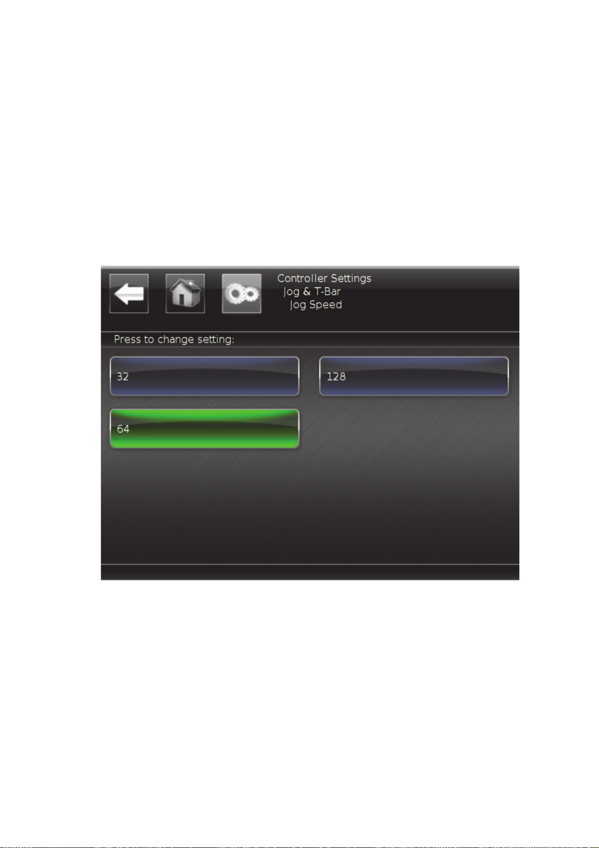
ConfiguringtheJog
Configure the standard rate of frame advancement when the Jog is turned, and when
you activate fast jog mode.
To configure the Jog:
1. Press SHIFT, MENU to display the main screen.
2. Tap Controller Settings to display the Controller options.
3. Tap Jog & T-Bar to display the Jog and T-Bar options.
4. Tap Jog frames Per Cycle to choose the standard number of frames to forward or
rewind when the Jog is turned.
5. Make your selection. (Default is 64 frames per cycle.)
8.SystemConfiguration
100
To configure fast jog mode:
1. Press SHIFT, MENU to display the main screen.
2. Tap Controller Settings to display the Controller options.
3. Tap Jog & T-Bar to display the Jog and T-Bar options.
4. Tap Fast Jog to choose the number of frames to forward or rewind when the Jog is
turned in fast jog mode.
The value is a multiplier of the standard speed, therefore, changing the standard
speed will change fast jog speed.
Configuring the Jog |
 Loading...