

Page 1

MobileSat
Optus MobileSat
®
Mobile Satellite Telephone – S2
User Manual
Page 2

Making a Call
Dial the destination phone number, including the STD code.
Press the key to start the call.
Answering a Call
Press any key (except and ) while the phone is ringing
or remove the handset from the cradle.
During a Call
Adjust volume using / on the side of the handset. Hold
the mute key to inhibit your voice transmission but still allow the
other party to be heard.
Speed Dialling
Press NN or *NN (memory number) and then hit to call a
known number. The phone number will be displayed during call
setup.
OR
Press NN or *NN (memory number) to view the memory
and then hit to call the number.
Repeat Dialling
If the called number is busy, then press to start
repeat dialling. This automatically redials the number three
times at one minute intervals, depending on Earth Station
settings.
Last Number Redial
From the Standby screen, press / to view the last
dialled number. Continue to press this key to review the last 5
numbers.
Correcting the Number
Press the key (momentarily) to erase the last entered digit,
or press (hold) to delete all the entered numbers.
Illumination
To turn on the backlight during poor lighting conditions, press
the mute key while Standby is displayed.
CLR
CLR
-
+
SND
FCN
SND
RCL
SND
-
+
ENDPWR
SND
QUICK REFERENCE GUIDE
Optus MobileSat
®
COMMITMENT TO CUSTOMER
SATISFACTION
Dear Customer
Congratulations on purchasing this high quality Optus MobileSat
product.
Optus Networks Pty Ltd is committed to giving top priority to
customer satisfaction through relentless efforts to provide
better products and better service.
Should you require assistance with regard to your new Optus
MobileSat S2 phone, you are requested to direct your inquiry to
the Authorised MobileSat Dealer from whom you purchased your
phone.
THIS MANUAL BELONGS TO:
PHONE NUMBER:
Page 3

The instructions in this User Manual make it easy to operate your
new Optus MobileSat
®
Mobile Satellite Telephone – S2, the Optus
MobileSat S2. To make a simple phone call or to receive a phone
call, you need to refer to the instructions in Chapter 1 and Chapter 2.
For more advanced operations of the Optus MobileSat S2, read
Chapters 3 to 6.
Chapter 1 – PRELIMINARY INFORMATION:
This section tells you what you receive in the Optus MobileSat S2
Basic Configuration, how to obtain optimum performance and
instructions about safety.
Chapter 2 – OPERATING INSTRUCTIONS:
Phone's features and how to place and receive calls.
Chapter 3 – DISPLAYS AND ALERTS:
Lists commonly displayed messages, functions and status displays.
Alarm/alert messages and tones are also explained.
Chapter 4 – PHONE NUMBER MEMORIES:
Dialling and number storing capabilities of the Optus MobileSat S2
phone. Operation of these capabilities is explained in step-by-step
detailed procedures.
Chapter 5 – ADVANCED OPERATING INSTRUCTIONS:
All operating instructions, that are not covered in the Operating
Instructions (Chapter 2) or the Function Extensions (Chapter 6).
Chapter 6 – FUNCTION EXTENSIONS:
Details each function command which allows you to configure and
monitor the Optus MobileSat S2 operation. The function menu is a
series of displays that can be used to remind you which numbered
keys to use for various function key (ie, FCN) operations.
Chapter 7 – OPTIONAL ACCESSORIES:
Defines some options available from Optus MobileSat.
*Optus does not support this function.
I
QUICK REFERENCE GUIDE HOW TO USE THIS MANUAL
FCN 1
Time
Functions
FCN 2
Unit Status
Functions
FCN 3
Terminal
Option/Setup
FCN 4
Tone
Functions
FCN 5
Screen
Functions
FCN 6
Lock
Functions
FCN 7
Clearing
Functions
FCN 8
Message/CUG
Functions
FCN 9
Antenna
Functions
1
Call Time
FCN 11
Own Number
FCN 21
2W Tel/Fax
FCN 31
Ring Volume
FCN 41
Backlight
FCN 51
Lock Code
Set
FCN 61
Time Clear
FCN 71
Recall Sys
Op Msg
FCN 81
Antenna
Adjust
FCN 91
FCN 0 and FCN 9 are used during digit
entry give a pause or wait digit.
2
Total Call
Time
FCN 12
SW Version/
ESN
FCN 22
Horn
FCN 32
Ring Pitch
FCN 42
Contrast
FCN 52
Lock Mode
FCN 62
Clear Last
Numbers
FCN 72
Messaging
FCN 82
Antenna
Calibrate
FCN 92
3
Outgoing Call
Time
FCN 13
Zone/Class
FCN 23
Auto Answer
FCN 33
Ring
Cadence
FCN 43
Wakeup
Screen
FCN 53
Auto Lock
Enable
FCN 63
Number
Prefix
FCN 73
Distress
Message
FCN 83*
Antenna
Tracking
FCN 93
4
Call Time
Beeps
FCN 14
GPS Location
FCN 24
Ignition Lock
FCN 34
Tone Volume
FCN 44
Call Credit
FCN 64
Memory
Clear
FCN 74
Predefined
CUGs
FCN 84
5
Clock Set
FCN 15
Volts/Temp
FCN 25
2-Wire
Enable
FCN 35
Key Beep
Enable
FCN 45
Network
FCN 65
Edit CUG
Tex t
FCN 85
6
Clock Display
FCN 16
LED Display
FCN 26
System ID
Download
FCN 36
DTMF Tone
FCN 46
Lock Msg
Tex t
FCN 66
7
Alarm Log
FCN 27
Handsfree
Sensitivity
FCN 37
8 9
Primary Menu Secondary Menu
FCN (Hold) = View Hidden Digits
FCN SND = Repeat Dial
FCN (Mute) = Toggle RSSI/RSNR
FCN END = Terminate a current fax or
data call from handset
Page 4

HOW TO USE THIS MANUAL i
GENERAL 1
BASIC CONFIGURATION 2
NOTES ON SAFETY 3
CONTROLS AND FEATURES 5
PLACING A CALL 11
RECEIVING A CALL 22
DURING A CALL 27
DISPLAYS AND TONES 29
MEMORY 32
NAME TAGS 35
PHONE NUMBER STORING 39
SPEED DIAL 42
REPEAT DIAL 44
SCRATCHPAD MEMORY 46
LAST NUMBER REDIAL 48
CALL TIMERS AND CREDITS 49
PHONE LOCKS 50
AUTOMATIC LOCK 51
CONFIDENTIAL CODE 53
NUMBER SETS 54
HANDSFREE 58
SHORT TEXTS (MESSAGES) 60
MESSAGING 61
CONFIGURATION ACCESSORIES 66
ANTENNA ADJUSTMENT 77
MOBILESATANTENNA 78
MAST ANTENNA ADJUSTMENT 79
ANTENNA ADJUSTMENT 81
Chapter 8 – EXPERIENCING PROBLEMS:
Suggests some possible problems you may encounter, and ways to
overcome them.
Chapter 9 – GENERAL INFORMATION:
This covers such areas as copyrights, warranties and general
service information.
II III
HOW TO USE THIS MANUAL TABLE OF CONTENTS
Page 5

FCN 53: WAKEUP SCREEN 122
FCN 61: CONFIDENTIAL CODE 124
FCN 62: LOCK MODE 126
FCN 63: AUTOMATIC LOCK 128
FCN 64: CALL CREDIT 130
FCN 65: NETWORK 139
FCN 66: LOCK MESSAGE TEXT 140
FCN 71: TOTAL TIME CLEAR 142
FCN 72: CLEAR LAST NUMBERS 143
FCN 73: NUMBER PREFIX 144
FCN 74: INITIALISE 145
FCN 81: SYSOP MESSAGES 148
FCN 82: MESSAGE MODE 149
FCN 83: DISTRESS MESSAGE 153
FCN 84 & FCN 85: CLOSED USER GROUP (CUG) OPERATION 154
FCN 91: ANTENNA ADJUST 161
FCN 92: ANTENNA CALIBRATE 164
FCN 93: ANTENNA TYPE 168
P1: PROGRAMMABLE FUNCTION 1 170
P2: PROGRAMMABLE FUNCTION 2 172
OPTIONAL ACCESSORIES 174
EXPERIENCING PROBLEMS 175
SPECIFICATIONS 181
SERVICE INFORMATION 183
WARRANTY 184
REPORTING A FAULT 186
TRANSCEIVER TOP PANEL 187
MOBILESAT S2 COMPLETE PRODUCT CONFIGURATION 189
FUNCTIONS 86
FCN 11: CALL TIME 90
FCN 12: TOTAL CONNECT TIME 91
FCN 13: OUTGOING CALL TIME 92
FCN 14: CALL TIME BEEPS 93
FCN 15: CLOCK SET 94
FCN 16: CLOCK DISPLAY 95
FCN 21: OWN NUMBER 96
FCN 22: SOFTWARE VERSION/ESN 98
FCN 23: ZONE/CLASS/PRIORITY 99
FCN 24: GPS LOCATION 100
FCN 25: VOLT/TEMP 101
FCN 26: LED DISPLAY 102
FCN 27: EVENT/ALARM LOG 103
FCN 31: 2W TEL/FAX 104
FCN 32: HORN ALERT 106
FCN 33: AUTOMATIC ANSWER 108
FCN 34: IGNITION LOCK 109
FCN 35: 2/4 WIRE ENABLE 110
FCN 36: SYSTEM ID DOWNLOAD 111
FCN 37: HANDSFREE SENSITIVITY 112
FCN 41: RING VOLUME 113
FCN 42: RING PITCH 114
FCN 43: RING CADENCE 115
FCN 44: TONE VOLUME 116
FCN 45: KEY BEEP ENABLE 117
FCN 46: IN CALL DTMF TONES 118
FCN 51: BACKLIGHT CONTROL 120
FCN 52: DISPLAY CONTRAST 121
IV V
TABLE OF CONTENTS TABLE OF CONTENTS
Page 6

The Optus MobileSat S2 is designed to work directly with the
Optus B-Series satellites that is geostationary over the equator,
North East of Australia.
Therefore, for correct operation, there must be no physical
obstruction between your
Optus MobileSat S2 antenna and the
satellite overhead. Generally speaking, the satellite is in the
north sky, in the direction of the sun, mid morning.
Possible reasons for an obstruction to a clear view of the
satellite:
• Bridges overhead
• Large trucks alongside
• Nearby buildings
• Inside buildings (unless the antenna is near a window from
which you have line of sight to the satellite)
Medium tree cover does not prevent operation of the phone.
Your antenna should be adjusted correctly for the relevant
location in Australia. Refer to Map 1 on page 81, and the section
"Antenna Adjustment" or "Experiencing Problems" for more
details.
Use care in handling your phone, just as you would with your
home telephone.
• Do NOT leave your phone exposed to extreme environmental
conditions, such as high humidity, rain, high temperatures,
direct sunlight or dusty conditions.
• Do not clean with caustic or harsh chemicals.
The
Optus MobileSat S2 has a rechargeable internal battery which
may flatten if the transceiver is not connected to a power source
for an extended period.
For transceivers that are not permanently connected to a power
source (e.g. in storage or transportable case) Optus
recommends recharging the battery every three months.
Connect the transceiver to a power source for 48 hours every
three months of storage to keep the battery adequately charged.
GENERAL
1
GENERAL
1
1
LIST OF FIGURES
FIGURE 1 – BASIC CONFIGURATION 2
FIGURE 2 – FRONT VIEW 5
FIGURE 3 – REAR VIEW 6
FIGURE 4 – HANDSFREE CONFIGURATION 58
FIGURE 5 – FULLY OPTIONED POWER CONNECTION 70
FIGURE 6 – REMOTE TELEPHONE INSTALLATION 71
FIGURE 7 – EXTERNAL GPS CONFIGURATION 76
FIGURE 8 – ANTENNA ANGLE 77
FIGURE 9 – MAST ADJUSTMENT KNOB 85
FIGURE 10 – COMPLETE CONFIGURATION 189
LIST OF TABLES
TABLE 1 – DISPLAY DURING VOICE CALL 13
TABLE 2 – DISPLAY DURING 2W TEL/FAX CALL 15
TABLE 3 – DISPLAY DURING DATA CALL 18
TABLE 4 – ACCEPTED HAYES AT COMMANDS 18
TABLE 5 – TERMINAL RESPONSE 21
TABLE 6 – MESSAGE TYPES 63
TABLE 7 – LOCK OPTIONS 140
TABLE 8 – FACTORY SETTING OF FUNCTIONS 146
TABLE 9 – FAULT DESCRIPTIONS 178
VI
LIST OF FIGURES AND TABLES
Page 7
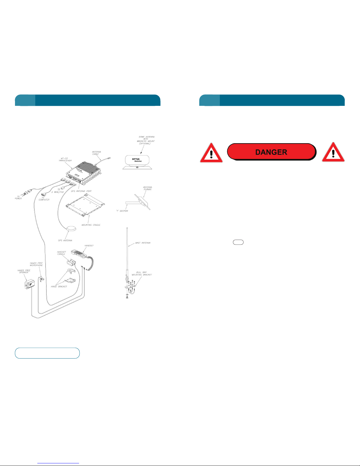
The following are instructions about Safety and Safety
Precautions when using your
Optus MobileSat S2 telephone.
Failure to heed these safety instructions could result in serious
personal injury and possible property damage.
RADIO FREQUENCY INJURY (RADHAZ): Your phone is a power
transmitting device. When the phone is in use, radio frequency
energy (RF) with a power output level of up to 4 watts radiates
from the antenna. When the unit is transmitting, avoid close
contact with the antenna and/or close exposure to the radio
frequency energy radiated from the antenna. (Transmission
occurs when the telephone user is talking or sending data.)
EXPLOSIVES: Radio frequency energy (RF) is a potential danger
near explosives. Turn off your phone when refuelling a vehicle or
when you are in areas of blasting operations or other hazardous
environments. ALWAYS OBEY ''Turn Off Two Way Radio'' signs.
Use the phone key to turn off the power.
TRANSPORTING EXPLOSIVES: Because of the danger of
explosion, NEVER store nor carry flammable gas and/or liquids
or explosive materials in the same compartment with your
satellite phone. Treat LP gas and containers as an explosive
unless correctly installed with ventilation for vehicle use.
MOBILE OPERATION: Refrain from using your phone while you
are driving a vehicle, even during hands-free operation. When a
call is received or you make a call, PULL OFF THE ROAD AND
PARK. It is illegal in some locations to use mobile and radio
telephones while driving.
It is necessary to turn off the phone at Petrol/Service Stations to
eliminate the chance of interference or potentially dangerous
radio frequency energy (RF) transmissions.
INJURY IN VEHICLE: Secure the phone in your vehicle to prevent
damage to the phone and personal injury in the event of an
accident.
PWR
NOTES ON SAFETY
2 3
BASIC CONFIGURATION NOTES ON SAFETY
1 1
Figure 1 – Basic Configuration
Page 8
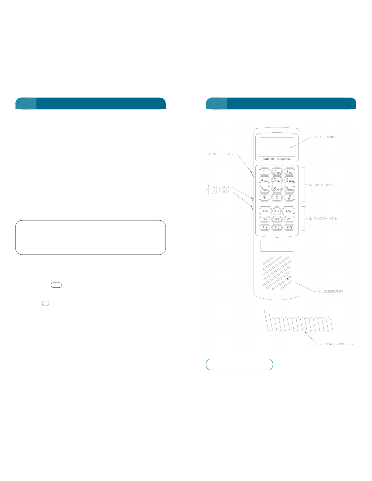
CONTROLS AND FEATURES
ELECTRICAL SAFETY: The Optus MobileSat S2 complies with
AS/NZS 60950-2000 and ACA TS 022-1997 technical standards.
ELECTROMAGNETIC INTERFERENCE WITH YOUR SATELLITE
PHONE: Speed Control, Engine Management computers, Anti-
Brake System, Fuel Injection System, Digital Instrument Panel
Displays, and High Wattage Audio Systems. These electronic
devices are usually protected in vehicle installations from
emitting electromagnetic radiation. A possibility exists that such
devices could interfere with proper operation of your satellite
phone. Alternatively, your satellite phone may interfere with
other devices. Consult your vehicle dealer and/or manufacturer's
representative should such problems develop.
The
Optus MobileSat S2 complies with AS/NZS CISPR 22-2002
and Radiocommunications (Electromagnetic Radiation – Human
Exposure) Standard 2003 (HES) technical standards.
IMPORTANT NOTICE: Users of this equipment should
note that, as with any radio transmitter, this equipment
is capable under some circumstances of causing
interference in other nearby electronic equipment.
Users should be considerate of others in this regard and where
appropriate, move their satellite telephone away from any nearby
affected equipment.
Note: The symbol indicates the SND key on the phone. A similar box is
used for all other keys (the numeric keys only show the number), within this
manual.
For example: the letters ABC are not shown.
COMPLIANCE LABELLING
The Optus MobileSat S2 complies with the applicable regulatory
requirements of the Australian Communications Authority (ACA)
and the regulatory compliance A-Tick label is located on the
underside of the telephone unit.
2
SND
4 5
NOTES ON SAFETY CONTROLS AND FEATURES
1 1
Figure 2 – Front View
Page 9
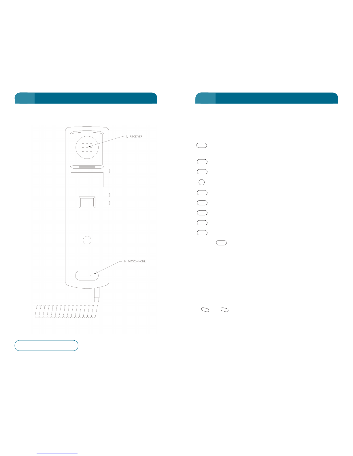
1. RECEIVER: Receives audio signals when handset is off hook.
2. Liquid Crystal Display SCREEN: 30 characters, 3 rows of 10
characters each.
3. FUNCTION KEYS:
Send (transmit) key. Initiates the call after number
selected.
End (phone hang up) key.
Power On/Off key. Must be held for 2-3 sec.
Store Key.
Recall Key for Stored Numbers.
Function (Menus and other functions) key.
Clear key.
Programmable Function key.
Programmable Function key.
Note: The key can be used for correcting the last key press by
pressing momentarily (less than 1 second) and may also be used to abandon
an action by holding for more than 1 second.
4. DIALLING KEYS: Telephone entry keypad “#”, “*” and “0-9” for
phone number, alphanumeric information, etc.
5. LOUDSPEAKER: Call alert and alarm tones when handset is in
the cradle. Not active if handsfree speaker is plugged in.
6. MICROPHONE
7. CURLED-TYPE CORD: Cord for the handset.
8. and KEYS: Volume increase and decrease or display
scroll up and down controls. (The “#” and “*“ keys also perform
these functions in the appropriate mode.)
-
+
CLR
P2
P1
CLR
FCN
RCL
STO
PWR
END
SND
CONTROLS AND FEATURESCONTROLS AND FEATURES
6 7
CONTROLS AND FEATURES CONTROLS AND FEATURES
1 2
Figure 3 – Rear View
Page 10
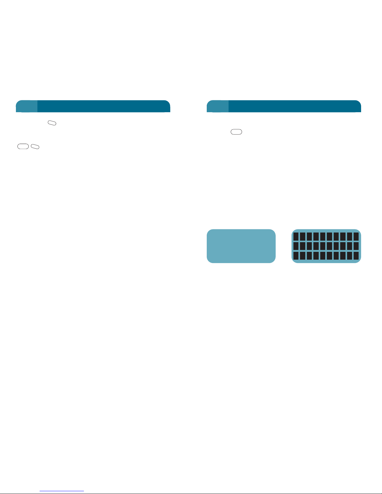
Turn ON
Press the key firmly (for at least 2-3 seconds). On a cold
startup the phone will take 10 seconds to provide service. At
power up, three events will occur, listed as items 1 through 3 as
follows.
1. Display and Keypad Illumination: Display and keypad
backlighting turns on.
2. Wake-up Display: A stored message will be displayed and a
series of short beeps occur. Thirty character displacement
blocks appear momentarily, then the phone goes to Standby
(displaying Signal Strength Indication SSI from 0-20). The
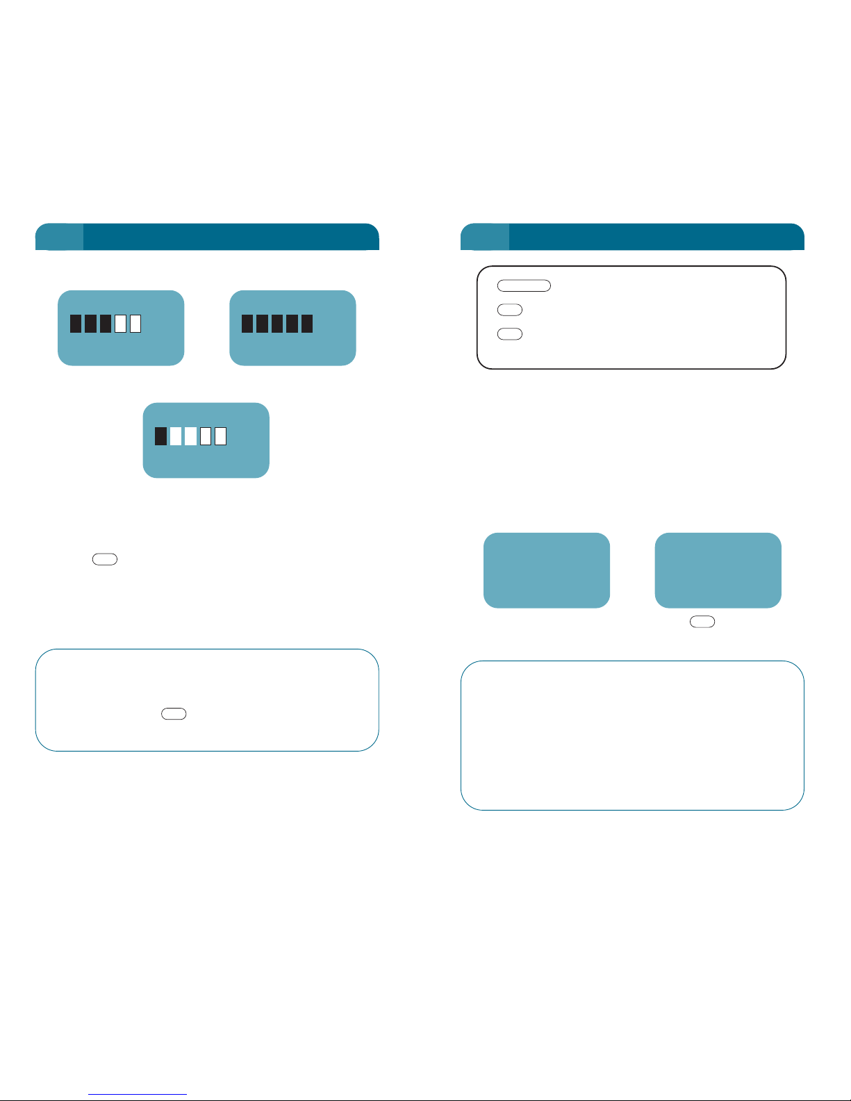
telephone gives an audible beep.
This display maybe altered using FCN 53. See “FCN 53:
WAKEUP SCREEN” on page 122.
3. Signal Strength Indication: This Standby display shows
satellite system signal strength by the number of blocks
shown (five blocks for the strongest signal). A number will
also show the signal strength between 1 and 20. The bigger
the number, the stronger the signal. (No number is displayed
if no signal is received).
The telephone gives a double beep when the Standby screen
appears.
PWR
9
9. MUTE KEY: Mutes the microphone when held down. Switches
on/off the backlight when not in voice mode. This key is also
used to toggle between alpha and lower case in digit entry mode.
is used to toggle between RSSI/RSNR display while
viewing the Standby screen.
M
FCN
M
8
CONTROLS AND FEATURES CONTROLS AND FEATURES
2 2
Default Start Up Message 30 displacement blocks
Optus S2
MobileSat
Telephone
Page 11
STANDBY Display
Turn OFF
Press the key firmly (for at least 2 seconds).
The configuration of the unit to include ignition control, PC
connection, Horn Alert, SCADA (Supervisory Control And Data
Acquisition) setting or 2-Wire operation, alters the basic
operation of the ON/OFF control.
Call-In Progress protection: If the vehicle ignition is
turned Off for some reason during the conversation,
power to the phone is not turned Off until the end of
the call (when the button is pressed or the 2Wire handset placed “On Hook”).
END
PWR
10
(Weaker Signal) (Strong Signal)
Standby
Before a successful call can be made, the phone must display
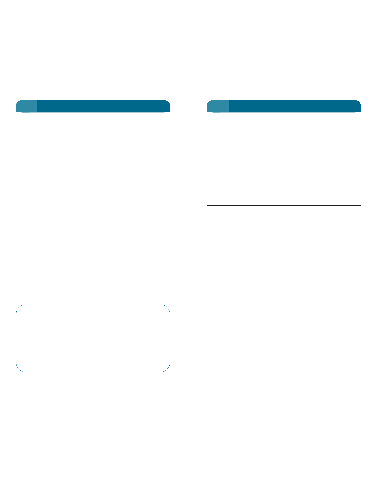
Standby and an adequate receive signal strength.
Enter Phone Number
Enter the number you want to call. The numbers as entered,
appear left to right on the display. You may check them for
accuracy before sending.
In the following example, the number is 03 9264 3050.
STD Area Code
Except for the following calls, the STD Area Code must
be used. eg. 03 9264 3050 even while in Melbourne. IDD
prefixes may also be used.
• 000 Emergency calls
• Operator connected calls
• National numbers generally beginning with “1”
• 008, 013
11
CONTROLS AND FEATURES PLACING A CALL
2 2
(Inadequate Signal)
06
No Service
02
Standby
16
Enter phone number
Start the call request
(Hold) Erase the number displayed
and return to Standby screen
CLR
SND
PHONE NO
(Phone Number Entered) (When Key Pressed)
SND
0392643050
0392643050
Calling
Page 12

View Hidden Digits of Long Phone Number
(Hold) To view long phone number that exceeds display
capacity. The
Optus MobileSat S2 can store phone numbers up to
32 digits.
To Correct an Entry before sending
(Momentarily) To erase digit last entered to first entered,
one at a time.
(Hold) To clear display and return to Standby.
Configuration of phone locks may restrict your ability to make
calls. Refer to Chapter 5 page 50.
Table 1: Handset Displays during a Voice call from the Optus
MobileSat S2 Handset
Displays Description
Standby Normal idle mode for the
Optus MobileSat S2,
will be observed at the beginning and the end
of a call.
Calling Outgoing Tel call initiated.
Call Alert Incoming Tel call.
In Use Tel call in progress.
Clearing Tel call clearing.
CLR
CLR
FCN
13
Start Call
key to transmit entered digits.
Display will change to "Calling" and then ring tone, busy tone or
a recorded voice announcement will be heard.
If ring tone is heard then wait for called party to answer.
When the phone is answered the "In Use'' message will be
displayed, as shown.
ATTENTION
If the key is pressed without dialling a number, the last
telephone number will be displayed. If you press the key
while the ''No Service'' message is displayed, the Error Tone
will sound. (See Chapter 3, Displays and Tones.)
If there is no answer or "Busy" then finish the call with the
key.
End Call (Hang Up)
After you have finished talking, press the key to finish
the call.
“Clearing...” will be displayed, before returning to Standby.
Simply replacing the handset in the cradle will not end the call.
END
END
SND
SND
SND
12
PLACING A CALL PLACING A CALL
2 2
In Use
Page 13
To end a call
Replace the 2 wire phones handset, or set the phone On Hook.
Number Sets stored in the phone may be recalled for commonly
called numbers.
Configuration of phone locks may restrict your ability to make
calls.
Note: The TEL/FAX port of the Optus MobileSat S2 can be set to allow only
voice calls to be made. Refer to Configuration Accessories on page 71.
Table 2: Handset Displays during a 2W Tel or Fax Call
Displays Description
Standby Normal idle mode for the
Optus MobileSat S2,
will be observed at the beginning and the end
of a call.
TEL & FAX Outgoing Tel or Fax call initiated.
Started
IC DAT/FAX Incoming Tel or Fax call.
Started
TEL & FAX Tel or Fax call in progress (Transmit/Receive).
In Use
TEL & FAX Tel or Fax call clearing (Transmit/Receive).
Clearing
TEL & FAX Tel or Fax call ended (Transmit/Receive).
Ended
15
2 Wire Configuration
It is possible to connect a normal telephone to the
Optus
MobileSat S2
TEL & FAX port to make and receive calls. This
includes a standard cordless phone. Due to the system protocol,
ISDN functions and pulse metering (for coin phones) are not
supported by
Optus MobileSat S2 telephones. See Function 35 to
enable the TEL/FAX port.
To make a call
Lift the handset from the phone and wait for a steady dial tone.
This dial tone indicates the phone is in Standby mode. Dial the
phone number using the phone’s keypad and press the Flash
button to indicate that no more digits are to be entered. Note
that a prefix digit may be required before entering the
destination phone number (see page 71). If the Flash button is
not pressed, the
Optus MobileSat S2 transceiver will wait a
short time before assuming the complete number has been
entered, and will then start the call setup with this phone
number. A beep tone indicates the start of the call connection.
If less than 3 digits are dialled, then the
Optus MobileSat S2 will
not attempt to connect the call, but will produce a busy tone at
the handset after a timeout period. After 32 digits are dialled
every attempt to dial more digits will produce a beep tone at
the handset and the digit entry will be ignored.
The ring tone will then be heard to indicate connection. A
failure to connect will result in a busy tone at the handset.
STD Area Code
Except for the following calls, the STD Area Code must
be used. eg. 03 9264 3050 even while in Melbourne. IDD
prefixes may also be used.
• 000 Emergency calls
• Operator connected calls
• National numbers generally beginning with “1”
• 008, 013
14
PLACING A CALL PLACING A CALL
2 2
Page 14

Placing a DATA Call
The
Optus MobileSat S2 Satellite telephone incorporates its own
modem within the transceiver. This internal modem responds to
a restricted set of standard Hayes modem commands.
To send data using the
Optus MobileSat S2 transceiver, it is
necesary to have a compatible data terminal which may connect
to the RS232 pins of the DATA & MAINTENANCE port.
A standard RS232 data communication cable is required to
connect the data terminal to the
Optus MobileSat S2’s DATA &
MAINTENANCE port.
Configuring the DATA Terminal
Configure the data terminal software package to have the
following settings:
Connection: Direct to Com1 (or Com2, 3 or 4)
Baud Rate: 9600bps
Parity: None
Stop Bits: 1
Flow Control: Hardware
Recommended FTP: Zmodem
DATA Operation (sending)
The data call dialling is controlled by entering Hayes AT
commands at the data terminal. The
Optus MobileSat S2 only
supports a restricted set of commands, refer to Table 4 on page
18 for this information.
To initiate a data call, type ‘atdt’ followed by the full STD number
of the destination you wish to dial.
For example: atdt0392643050
Call set-up time will be longer than for standard DATA
communications due to the added satellite delays. Once
connected, data can be sent. Optus recommends using the
“Zmodem” file transfer protocol (FTP) because of its usability
and robustness.
17
FAX Call (Facsimile Machine)
To send a fax using the
Optus MobileSat S2 transceiver, it is
necessary to have a compatible fax machine connected to the
TEL & FAX port of the transceiver.
A fax can be sent by following the instructions (on sending a fax)
of the fax machine. The dialling of the destination number is
described in ‘Placing a Call: 2 Wire Configuration’ on page 14,
and may require a prefix digit.
The
Optus MobileSat S2 transceiver operates transparently to the
fax machine. Once the fax machine has finished transmission,
the call will end automatically.
STD Area Code
An STD (or IDD) Area Code must be used for all fax
transmissions except for:
• Operator connected calls
• National numbers generally beginning with “1”
• 008, 013
The handset display will indicate that the transceiver is currently
being used in a fax call.
Fax sending may be restricted by phone locks of the phone, or if
the
Optus MobileSat S2 has been configured to have the fax
facility turned Off.
Note: The TEL/FAX port of the Optus MobileSat S2 can be set to allow only
fax calls to be made. Refer to Configuration Accessories on page 71.
16
PLACING A CALL PLACING A CALL
2 2
Page 15
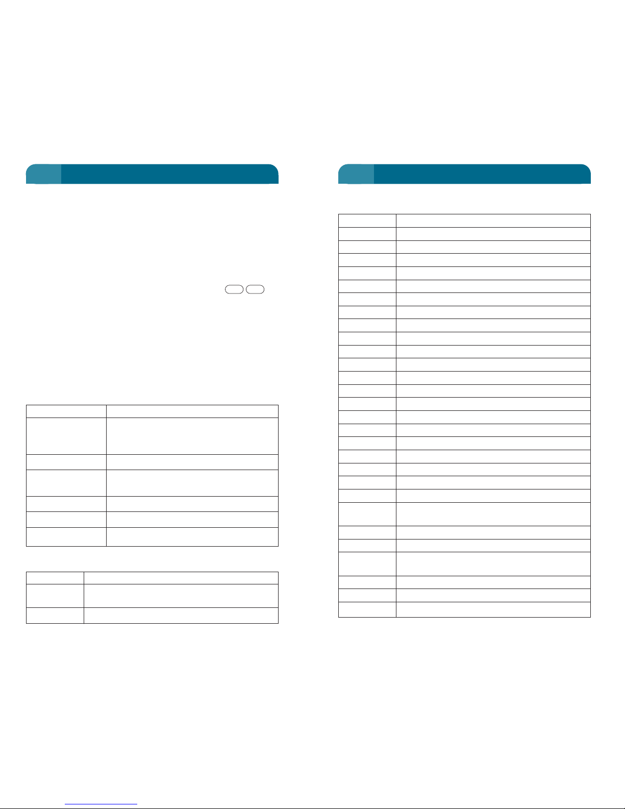
Table 4: Accepted Hayes AT Data Terminal Commands
(continued)
Command Description
AT This will return an OK or ERROR message
ATDTn Dial the number n.
ATH Go on hook, hang up
ATDL Redial the last number
ATDSn Redial any stored number (where n=0, 1, 2 or 3)
ATE0 Disable echo of commands
ATE1 Enable echo of commands
ATI0 Report Product code
ATI1 Precomputed checksum
ATI2 Report ‘OK’
ATI3 Report firmware version
ATI4 “MT-S2”. Report internal code revision
ATI5 Report Country Code
ATI6 Report Internal code revision
ATI255 Reports software build date
ATMn Set speaker volume (n = 0 – 3)
ATQ0 Enable result code (OK or ERROR)
ATQ1 Disable result code, quite mode
ATV0 Returns the result code in numerical form
ATV1 Returns the result code in text form
ATZ Soft reset and restore default configuration
ATO Return to data mode from command mode
(only if on-line)
ATSn Altering S-registers; (see S-registers list)
AT&D0 Modem ignores DTR (Data Terminal Ready)
AT&D2 Modem hangs up on DTR drop and goes to
command mode
AT&F0 User profile 0
AT&F1 User profile 1
AT&K0 No flow control
19
During a data call, the handset display will indicate that the
transceiver is currently being used via the “Data Port in Use”
display. Refer to Table 3 below for a full list of handset displays
during a data call.
Upon completion of your data transfer, the call can be hung up
by either typing the escape sequence ‘+++’ followed by ‘ath’, or
by dropping the DTR line (provided that the
Optus MobileSat S2 is
configured to monitor DTR status See page 20.) The call can also
be terminated through the handset by pressing the
keys.
The
Optus MobileSat S2 behaves transparently to the data
terminal. Once the data terminal hangs up the call, the
Optus
MobileSat S2
will cleardown the satellite channel.
DATA Operation (receiving).
For information on receiving data calls, see “Receiving a DATA
Call” on page 26.
Table 3: Handset Displays during a Data Call
Displays Description
Standby Normal idle mode for the
Optus MobileSat
S2
, will be observed at the beginning and
the end of a call.
Data Port Started Outgoing Data call initiated.
IC DAT/FAX Incoming Data call
Started
Data Port In Use Data call in progress (Transmit/Receive)
Data Port Clearing Data call clearing (Transmit/Receive)
Data Port Ended Data call clearing (Transmit/Receive)
Table 4: Accepted Hayes AT Data Terminal Commands
Command Description
A/ Re-execute command; can be used to place
another call of the previous call failed
ATA Phone off hook to answer incoming call
ENDFCN
18
PLACING A CALL PLACING A CALL
2 2
Page 16

DATA TERMINAL READY settings
The Optus MobileSat S2 modem by default ignores DTR. To
configure the Optus MobileSat S2 to hangup on DTR drop and
then return to command mode, enter the AT command
‘AT&D2S25=10’. This setting can be saved using AT&W, and will
remain in memory provided you power down the Optus MobileSat
S2 with the PWR button on the handset.
Table 5: Terminal Response
Displays Description
OK Data Communications between PC + Optus
MobileSat S2 is established. Command has
been processed satisfactorily.
No Carrier The Optus MobileSat S2 is not in a state where
data calls can be established (e.g.: No Services).
Busy The Optus MobileSat S2 is in a call or cannot set
up a data call since the channel is not available.
The destination number may also be busy.
Error The command to the Optus MobileSat S2 has
not been performed satisfactorily.
Connect XXXX Indicates that the call has been established and
(after a short delay) data transfer can proceed.
Ring This indicates that an incoming data call is
ringing the local terminal.
The handset display will indicate that the transceiver is currently
being used for a data call and will not allow interruption to the
call.
21
Table 4: Accepted Hayes AT Data Terminal Commands
(continued)
Command Description
AT&K3 CTS flow control
AT&K4 Software flow control
AT&K6 CTS & Software flow control
AT&V Displays current configuration and stored profile
AT&Y0 Optus MobileSat S2 will use modem profile 0
AT&Y1 Optus MobileSat S2 will use modem profile 1
AT&W0 Store current configuration in profile 0
AT&W1 Store current configuration in profile 1
AT&Zn = x Save dial number (where n = 0, 1, 2 or 3, x =
PSTN number)
Optus MobileSat S2 Default Modem Settings
Active Modem Profile:
ATE1 Enable echo of commands
ATQ0 Enable result code
ATV1 Returns the result code in text mode
AT&D0 Modem ignores DTR
AT&Y0 Optus MobileSat S2 will use modem profile 0
S–Registers
ATSn Sets and reads the selected register
ATSn=x Set the register n to the value x
ATSn? Reads the value of register n
MOBILESAT S2 Default S–Register Settings
Register 0 = 2 Automatic answer after 2 rings
Register 2 = 43 Escape sequence character ‘+’
Register 3 = 13 CR = carriage return
Register 4 = 10 CTRL-J = line feed character
Register 5 = 8 CTRL-H = backspace
Register 12 = 50 Escape sequence guard time (in Secs)
Register 25 = 10 Loss of DTR (in x100mSecs)
20
PLACING A CALL PLACING A CALL
2 2
Page 17
Answer Call
Press any key (except or ) while ringing to connect
you with the calling party.
OR if the handset is in the cradle, removing it will answer the
call.
The display will show, as per example.
Answer Call if in Auto Answer Mode and handset is in
the cradle
Wait 5 seconds (2 rings) and the telephone automatically
answers (Refer to "FCN 33: AUTOMATIC ANSWER" on page
108).
OR remove handset from the cradle.
OR push any key.
When answering a call without picking up the handset,
ensure the hands free option is installed, and ignition
input is active.
End Call (Hang Up)
To finish a call from the handset, the key must be
pressed. Replacing the handset in the cradle will not
terminate the call.
END
ENDPWR
23
RECEIVING A CALL
The phone MUST BE ON to receive calls.
If the phone is On and in Standby mode it will alert you to an
incoming call.
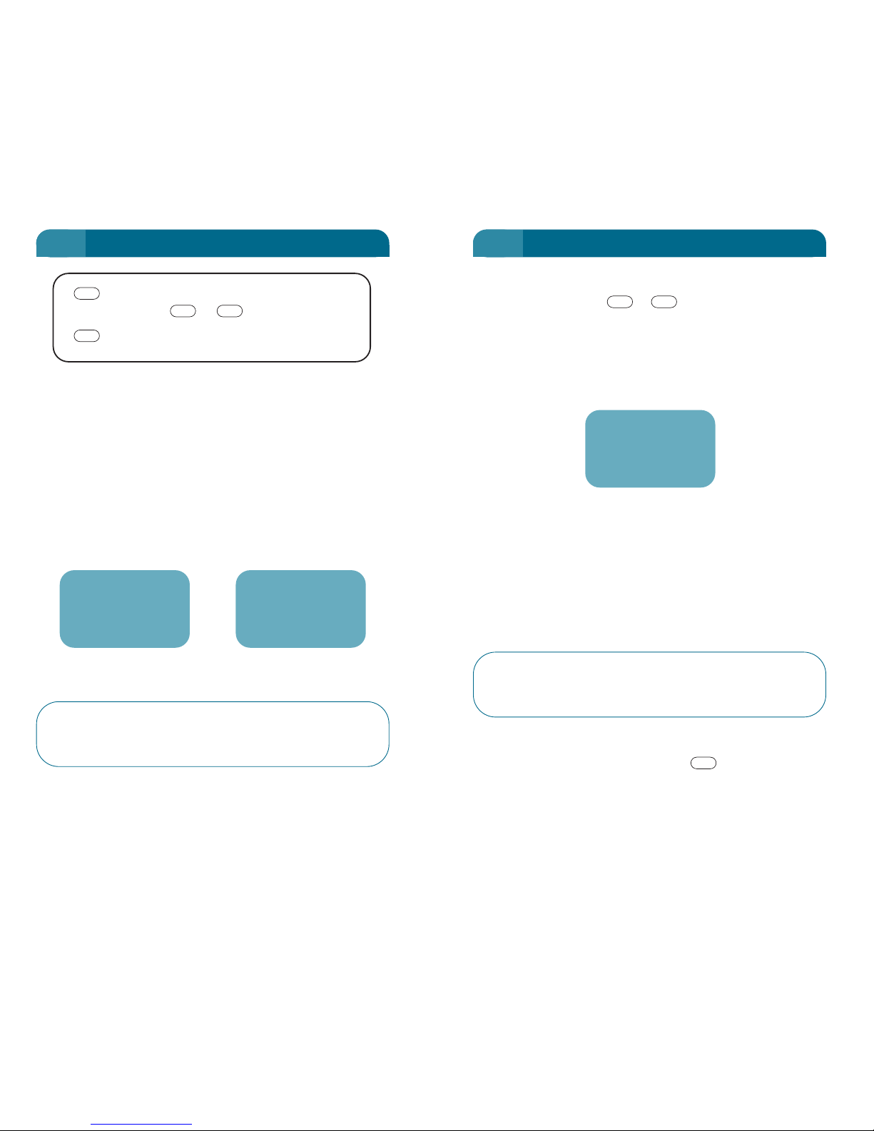
The phone will initially display "Call Alert". See note below.
Your phone will then sound the Call Alert Tone (if on), and "Call''
will flash repeatedly on the display.
If the incoming call is unanswered, ''Called'' will be on the
display and will remain there until display is cleared
(See page 24).
When "Call Alert" is received, the telephone is about to
ring. You must wait until "Call" appears before you can
answer as the call is still being set up.
22
RECEIVING A CALL
2 2
Answer (press any key except
or )
Hang Up
END
ENDPWR
Call
Alert
Call
(Incoming call being set up) (Incoming Call –
Flashing. Ring tone)
In Use
Page 18

2 WIRE CONFIGURATION
VOICE Call
To receive a call when using a 2 Wire phone and no transceiver
handset is installed, it is recommended that the transceiver be
powered up using the ignition control line. See FCN 35 to enable
the TEL/FAX port.
To receive a call
When the handset rings, just lift the handset Off Hook and the
connection is made. Conversation is then possible.
To end a call
Replace the handset, or set the phone On Hook.
FAX Call
The Optus MobileSat S2 automatically directs the call to the fax
machine connected to the TEL/FAX port if FCN 31 has fax
operation activated. The fax machine can be set to answer the
call automatically after several rings.
The call ends automatically on completion of the fax
transmission.
Note: The phone number for the transceiver to receive incoming calls can be
different for voice, fax, or data calls. Refer to "FCN 21: OWN NUMBER" on
page 96.
25
RECEIVING A CALL
Unanswered Call
This display indicates that a call was received, but was not
answered by your phone.
It will also show the time of the last call, and the number of
unanswered calls received since the phone was last used.
24
RECEIVING A CALL
2 2
Called 5
11:43am
Page 19

Using the Optus MobileSat S2 Telephone for the First Time
The first time you use the Optus MobileSat S2 telephone, you will
notice a delay in the voice transmit and receive. This is due to the
time delay in transmitting the information from the telephone to
the earth station via the satellite (a return distance of
approximately 72,000 km). To optimise the conversation, it is
recommended that you wait until the other end of the connection
has finished talking before you begin.
Earpiece and Loudspeaker VOLUME
The or key adjusts the handset speaker volume up or
down while in a call.
Pick up handset
If you have answered the call without picking up the handset,
it can be picked up later, disabling the handsfree mode, and
reverting to normal handset operation.
Note: Replacing the handset during a call does not "hang up" the call.
Send DTMF digits
To send codes to other systems, (eg. banking, "End to End" or
"DTMF") tones may be sent. Refer to FCN 46 for full details on
how to enable this option.
Note: If FCN 46 (DTMF Tones) is enabled, pushing keys will cause these
tones to be heard by the far end party.
Function Extensions
During the call, it is possible to use all the Function
Extensions, with the exception of FCN 82 (sending a message)
or FCN 84 (joining a CUG). A useful function during a call is
FCN 11 which shows the current call time.
Mute or Unmute the phone
• Press and hold down to silence (mute) the microphone,
so that the far party cannot hear your conversation. You will
be able to hear the third party but they can’t hear you. The
words "Mic Mute" will be displayed on the handset. It is not
possible to mute the handset earpiece.
M
-
+
27
DURING A CALL
Receiving a DATA Call
Provided that your terminal is configured correctly, RING will be
displayed by the terminal package for each incoming ring tone.
The incoming call can be answered automatically or manually.
Note: To ensure call setup, it is recommended that the call be answered as
quickly as possible.
Typing ‘ata’ will manually answer the incoming call. To answer
the call automatically after ‘x’ number of rings, use the
command ‘ats0=x’. For optimum performance and to minmise all
setup time, Optus recommends that ‘x’ be no greater than 2,ie.
ats0=2.
The receiving end need not perform any functions during data
transfer, the sending end has control.
The Optus MobileSat S2 will clear the call when requested to do
so by the data terminal at either the sending or receiving end.
For further information, see Table 4 on page 18 for the Hayes AT
command set.
26
RECEIVING A CALL
2 3
Page 20
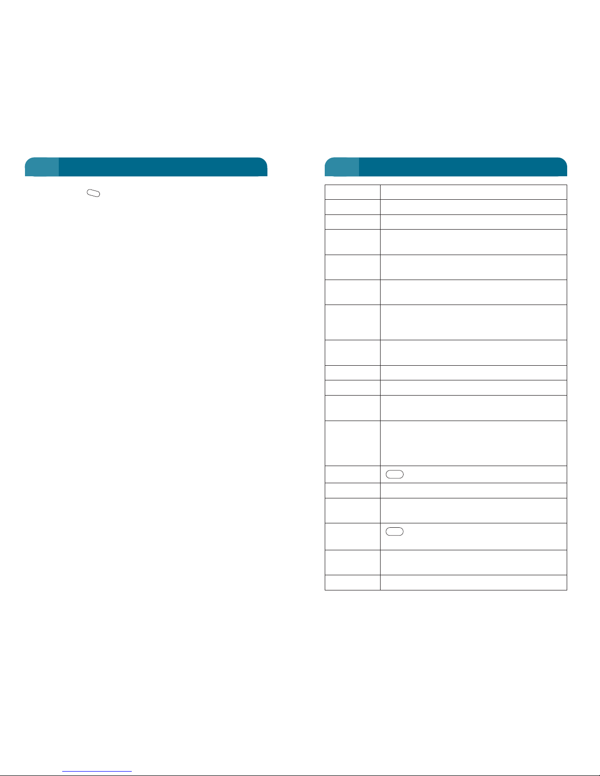
Display Function
abc) Phone is in Name-Tag mode. (lower case)
ABC) Phone is in Name-Tag mode. (upper case)
Another call Attempt to use the phone while it is busy with
is in progress another call.
Call Incoming call ring tone. "Call" display flashes
while phone is ringing.
Call Alert Call setup in progress. Wait for "Call" to be
displayed before answering.
Call is in FCN 82 attempt to send a message while a
progress - call is in progress.
Cannot SND
Called Called-in-absence indicator "Called" remains
on display until cleared (erased).
Calling Displayed during an outgoing call setup.
Clearing Call is clearing
Data port in Data call is in progress
Use
Fault (X) Your phone tests itself for irregularities.
These usually do not prevent the phone from
working, but should be reported to your dealer
as a non-urgent matter.
FCN key is pressed. Refer to page 86.
FL Phone is in Full Lock mode.
HA FCN 32, Optional Horn Alert mode activated
(horn, lights etc.).
HD (Hold) displays the Hidden Digits in a
long phone number.
I/C Data/Fax A fax or data call has been started
Started
IC Call Failed An incoming call attempt failed.
FCN
FCN
29
DISPLAYS AND TONES
• Release the to return to normal operation.
Scratchpad Memory
You may be given information that you wish to store such as a
new phone number or person's name (name tag). This can be
entered on to the scratchpad (as seen on the screen) for saving
to a memory location during or after the call is complete. See
page 46.
M
28
DURING A CALL
3 3
Page 21
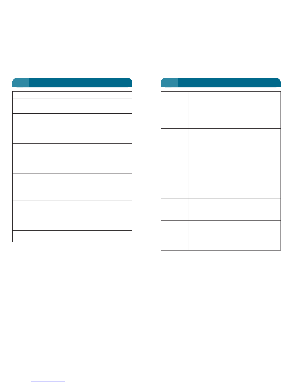
Handset Function
Tones
Alert Tone Indicates that a call is being received, i.e. the
phone is ringing.
Call Initiated Indicates that the phone is setting up or
Tone clearing down a call.
Call Time The Call Time Beep function operates in two
Beep modes, depending on whether the Credit
facility has been set or not. If the Call Credit
facility is Off, then Call Time Beep will sound a
beep ten seconds before the end of each
minute. These beeps may be turned off using
FCN 14. Refer to page 93. If Call Credit facility
is On, then call beeps will operate in
accordance with Call Credit User Manual.
Double Beep Indicates a New message, Fault Display or
Incoming Call, or end of programming (P1/ P2)
mode. On power up, a double beep indicates
that the Standby screen is displayed.
Error Tone Phone detects key or keypad entry errors, and
you are alerted to correct the entry. Error tones
are high pitched. Refer to FCN 44, page 116 to
adjust volume.
Key Tone A short high pitched tone, indicating that a key
has been pressed. Refer to FCN 45, page 117.
Network Indicates call progress through the telephone
Progress network.
Tones
Note: Other Status messages appear on the display as you operate the
phone. Read the procedures in this manual for description.
31
DISPLAYS AND TONES
Display Function
In Use Call in Progress.
Message Flashes when User Message is received.
Mic Mute Microphone is muted. The other party
remains audible on the speaker. Refer to
page 27.
No Reply The phone sent a packet to the earth station,
but no reply was received.
No Response An outgoing call attempt failed.
No Service Weak, lost or invalid signal, when phone is
unable to receive the signal from the satellite,
has found an invalid signal, or has been denied
logon to the system.
PL Phone is in Partial Lock mode.
RD Phone in Repeat Dial mode, refer to page 44.
Standby Displayed when phone is receiving a valid
satellite signal.
System Flashes when a new System Operator
Message Message (SysOp Message) is received. Refer to
page 148.
Tel/Fax 2W Tel or fax call started
Started
Tel/Fax 2W Tel or fax call in progress
In Use
30
DISPLAYS AND TONES
3 3
Page 22

Non Locked Numbers – 99 locations (01-99)
These locations are available to store information or recall
information when the phone is not in Partial or Full Lock. With
any lock applied, these memory locations cannot be recalled.
Partial Lock Numbers – 79 locations (*01-*79)
These locations are available to you to recall and send when the
phone is in Partial Lock mode without the need to know the
Confidential Code. These memory locations may not be edited in
Partial Lock mode. These memory locations cannot be recalled
in Full Lock mode.
Emergency Numbers – 20 locations (*80-*99)
These locations are preloaded with Emergency numbers. These
can be recalled and dialled in Partial or Full Lock mode. The
prestored information cannot be changed from the handset, only
by an Authorised MobileSat Dealer.
Last Number Memory – 5 locations (LN0-4)
The last five numbers dialled are stored and may be recalled for
re-transmission. These include any that were recalled from
memory 01-99 or *01-*99. These numbers cannot be recalled
while in Partial or Full Lock mode. Refer to page 48.
Scratchpad Memory – 1 location
The scratchpad allows you to write notes/numbers during a call
and store in one of the 178 main memory locations. Be aware
that the scratchpad information cannot be stored in Partial or
Full Lock mode. Refer to page 46.
Pre-Stored User Messages – 40 locations
It is possible to send and receive pre-stored messages. Refer to
page 150.
CUG Identification Settings- 9 locations
These are 30 character screen displays to show CUG settings.
Refer to CUG User Guide on page 154.
33
MEMORY
This section gives an explanation of the expected displays,
available options and methods of controlling the memory and its
contents.
• First, the definitions of the various memory locations are
shown below. The Optus MobileSat S2 has 198 memory
locations to store phone numbers, 01-99 and *01-*99.
• The section then explains the name area, or Name Tags
mode.
• There are several methods of storing the number, explained
in PHONE NUMBER STORING page 39. How to edit the
information is also shown.
• Recall of the number, allowing speed dialling is shown in
SPEED DIAL on page 42.
The Optus MobileSat S2 has several banks of memory for storing
phone numbers.
• Location 01-99 Non Locked Numbers
• Location *01-*79 Partial Lock Numbers
• Location *80-*99 Emergency Numbers
• Last Number Memory (5 locations)
• Scratchpad Memory (1 location)
• Pre-Stored User Messages (40 locations)
• CUG (Closed User Group) Identification Settings (9 locations)
The Optus MobileSat S2 can store and display phone numbers
and important information such as: name, extension number,
customer account number and other information.
Each location has a capacity for 32 digits plus 10 alphanumeric
characters, including spaces.
The memory may be configured by the user (from the handset)
or by an Authorised MobileSat Dealer.
Memory banks may be restricted to authorised users only by
setting Full or Partial Locks (see page 50) with a Confidential
Code (see page 53).
32
MEMORY
4 4
Page 23
Pressing or again (second time) will allow you to
enter lower case alpha characters. Pressing or
again (third time) will return you to numerical mode.
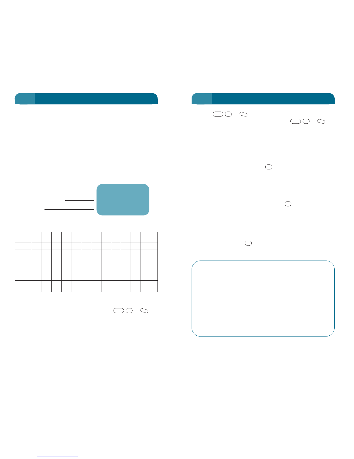
The keypad has Australian Standard telephone key letter/number
symbol assignments.
You may also use "&", "-", " ‘ ", "#", and "*" as characters in
Name Tag mode.
Note: The "#" is NOT entered using the key.
While in Name Tag Mode, you can also enter numbers into the
same fields, however the numbers are now part of the Alpha
Numeric set and will need to be entered as the fourth (or fifth for
7 and 9) keystroke.
For example, a single keystroke (press) of in this function
gives letter A, two keystrokes = B, three keystrokes = C, four
keystrokes = numeral 2.
Normally when a different key is pushed, it means to start a new
character entry, however it is possible that you may wish to enter
the letter "A" twice, and two pushes of the key will give "B"
instead. In this case the key is used to separate the
characters. The "#" does not appear on the display.
PAUSE FCN 0
To place a 2 second pause in a number, use Function 0.
This will show as a “P” in the number. This function
operates only when entering a phone number.
WAIT FCN 9
To place a “Wait for SND” command between sets of
numbers, press Function 9. This function only operates
when entering a phone number. Refer to the NUMBER
SETS chapter for details of sets of numbers on
demand.
#
2
#
M
#
FCN
M
#
FCN
35
NAME TAGS
Each phone number in the main memory can have a short (10character) message attached to it. This message is displayed
with the phone number when this memory is recalled.
The alphanumeric display information is organised as follows:
• Telephone numbers appear in the upper two lines. The bottom
line is for related Alphanumeric information. The Name Tag
function symbol shows when you are in Alphanumeric
Character Entry mode.
• When a telephone number is dialled from memory, only the
phone number is used, the Name Tag information is not sent.
To enter the characters "A" to "Z", (called Alpha Characters), you
will need to enter the Name Tag Mode using or ,
after at least one digit is displayed on the screen.
This function will allow you to enter upper case alpha
characters.
M
#
FCN
34
MEMORY
4 4
ABC) 00111
2122643111
Carol X902
Function Symbol
Telephone Number
Name Tag
ALPHANUMERIC KEY ASSIGNMENTS
No. Key
1
ABC DEF GHI JKL MNO PQRS TUV WXYZ
0 * #
Press
2345 6789
1 1 A D G J M P T W 0 * Separate
2 1 B E H K N Q U X 0 # Space
3 1 C F I L O R V Y 0 & Double
Space
4 1 2 3 4 5 6 S 8 Z 0 ‘ Triple
Space
5 1234567890–Four
Spaces
Page 24
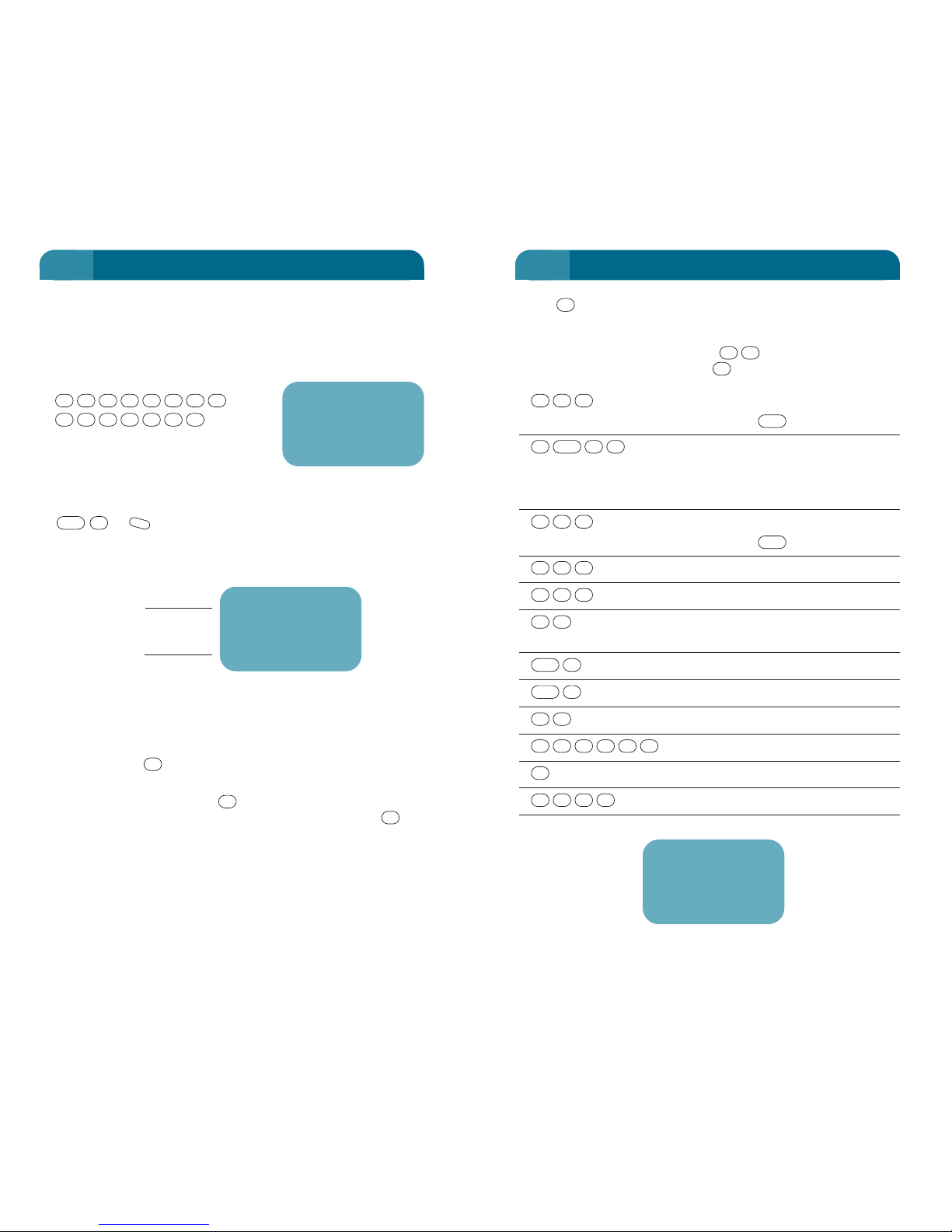
• The key is NOT required as a separator when a different
key is pushed for the next letter, but may be pushed once
without effect.
• To get the space character, use in sequence. A second
space is displayed, if you push for a third time etc.
ABC 2 C
3 pushes of to get C
ABC 2 a
The # is needed to distinguish
between the letters C & A of button
2. Function # goes to lower case.
PQRS 7 r
3 pushes of to get to R
MNO 6 o
JKL 5 l
# Space
Two #’s in a row is a single space
To go to Numerical mode
To go to Alpha (uppercase) mode
WXYZ 9 X
WXYZ 9 9
00
ABC 2 2
2222
0
99999#
99
#
FCN
#
FCN
##
555
666
7
PQRS
777
2#
FCN
#
2
ABC
222
#
##
#
37
NAME TAGS
EXAMPLE:
You wish to store telephone number 0011 1 212 264 3111 with
Alphanumeric (Name Tag) information “Carol X902". Carol
appears to be in New York USA, but the long number is used
here to give you a full display.
to enter the phone number.
The display will show it on two lines.
Note: At least one digit must be entered to the display to enter Name Tag
mode.
or or to enter Name Tag mode (upper case). The
display shows the alpha symbol and a cursor. The cursor is
where the alphanumeric characters appears.
Now that you are in the Name Tag mode enter your required
Alphanumeric information eg. ''Carol X902'' using the key push
sequence shown below.
Note: The use of the key to separate letters is required where they are
both on the same key,
eg. the letters C and A both use the key. A move to the next space must
be done before the second letter can be entered. You must press the key
to indicate that you have finished putting in the letter C after the third push
and that you now wish to put in the letter A.
#
2
#
M
#
FCN
1113462
21211100
36
NAME TAGS
4 4
00111
2122643111
ABC) 00111
2122643111
–
alpha
cursor
ABC) 00111
2122643111
Carol X902
Page 25

Store in a Specific Location
Enter phone number and the Alphanumeric information. The
last character in the sequence is followed by where
XX = desired two-digit memory location (01-99) or
where *xx = desired memory location (*01-*79). If the
location is empty, the information will be automatically stored.
If the selected memory address is occupied, the current
memory contents will appear and flash repeatedly. You may
choose to search for a Vacant Memory Location (using or
) or override the Old Memory using again.
Manually Search for a Vacant Memory Location
After entering the phone number and/or name tag, press
or to scroll display through Memory Addresses. The
current contents of each location is displayed on the screen.
When the desired location is determined, push to store the
information.
STO
-
+
STO
-
+
X
X
*
STO
XX
STO
39
PHONE NUMBER STORING
Store
See Phone Number storing in the following pages.
Error Correction: If an error is made prior to storing.
(Momentarily) to erase each character from last to first.
Note that if there is only one character and it is deleted, the
phone will return to Standby mode.
(Hold) to exit and not save information.
CLR
CLR
38
NAME TAGS
4 4
Enter phone number
Enter alpha description
Store in specified location
OR
(Hold) Store in next free location
STO
XX
STO
NAME TAG
PHONE NO
49)
0392643050
Bill
Memory Location
Phone Number
Name Tag
Page 26
Correct Alphanumeric Information After Storing
Press to display memory contents.
or to enter Name Tag Alphanumeric entry mode
(upper case).
Edit Alphanumeric information.
which overwrites the old information.
Erase a Memory Location
Return phone to Standby.
to store this blank display over existing memory.
STO
XX
STO
STO
XX
STO
M
#
FCN
XX
RCL
41
PHONE NUMBER STORING
Automatically Search for a Vacant Memory Location and
Automatically Store
(Hold for greater than 1 second) The phone automatically
finds the Lowest Vacant Memory Location and stores the
character sequence, with display response as per the
following example.
The display will return to the
number entry mode after 5
seconds, or when any key is
pressed.
Override an Old Number
If a Memory Address you have selected contains obsolete
information, you may choose to erase it and enter the new
data. The obsolete information will appear and flash
repeatedly.
Press again. The phone will return to the number entry
mode, with old information erased and the new information
stored.
Correct a Phone Number After Storing
Press or to display required
memory location.
Press (Momentarily) to erase one digit at a time.
Enter the correct (new) number.
or which overwrites the old
information.
STO
XX
*
STOSTO
XX
STO
CLR
XX
*
RCL
XX
RCL
STO
STO
40
PHONE NUMBER STORING
4 4
Stored 22
Page 27
Display Number Before Dialling
Recall memory address.
to dial and send the number if it is correct.
to cancel.
Having recalled a number, you may scroll up or down through
the memory. The order in which numbers are scrolled
(numerical or alpha), is affected by how you first recalled the
number to the display.
Scroll Display in Numerical Address Order
to display first position for numerical scroll.
/ to scroll display up or down numerical address
order.
to dial and send the displayed number.
Scroll Displays in Alphabetical (Name Tag) Order
with no trailing digits.
/ scroll display up or down alphabetical order.
to dial and send to the displayed number.
SND
-
+
RCL
SND
-
+
XX
RCL
CLR
SND
XX
RCL
43
SPEED DIAL
This section explains how to recall and send the phone numbers
stored by the methods explained in the previous chapters. The
Optus MobileSat S2 has 198 memory locations in two banks:
01-99 and *01-*99.
Note: The access to these numbers may be restricted by the LOCKS as
explained on Page 50.
Speed Dial
or One or two digits. The memory location will not
be displayed on the screen.
to dial and send the pre-stored number from the
memory location XX. Memories *01-*99 can also use this
facility.
The desired phone number may be recalled to the display, prior
to dialling or for confirmation. It is possible to step through the
memory in numeric or alphabetical order by toggling the
/ keys. (See next page.)
-
+
SND
XXX
42
SPEED DIAL
4 4
or Select Memory
OR
Wait
Send Number
SND
XX
RCL
XXX
Page 28
If Busy Signal is Heard
to cancel, "RD" will be displayed.
To Discontinue the Repeat Dial Command
(Hold) to exit while waiting for the next attempt to begin.
CLR
END
45
REPEAT DIAL
With the Repeat Dial feature, the phone automatically redials a
busy or no-answer number, up to three times, at one minute
intervals. If the call is successful then the Repeat Dial is disabled
for that sequence.
This feature is dependant on the configuration of the Earth
Station. Check with the MobileSat Helpdesk to ensure that
Repeat Dial service is available. Repeat Dial will not operate in
Partial or Full Lock mode.
Repeat Dial
will make a normal call, however if the
call fails due to cancellation or time out then the display will
show the phone number and ''RD'' for Repeat Dial.
The phone will redial the number after one minute.
Note: If the phone number was the last number tried, you do not need to reenter the number.
SND
FCN
PHONE NO
44
REPEAT DIAL
4 4
Enter phone number
Repeat Dial Mode and Start
If busy signal
To exit Repeat Dial Mode
CLR
END
SND
FCN
PHONE NO
RD
0392643050
Bill
Flashing
Page 29
Edit Scratchpad Memory
(Momentarily) will backspace the last character.
Note: If the DTMF (FCN 46) digits are being sent, the tone cannot be
retracted, and the button is not sent as a tone.
CLR
CLR
47
SCRATCHPAD MEMORY
During a call, you can use the display as a scratchpad to enter
information (phone numbers, names, address, etc.) that you may
want to save temporarily. It is possible to save the scratchpad
information in a vacant memory location during a call, or to save
it after the call is ended. Note that even though a ‘Clearing’
message appears on the display, once the call has cleared the
scratchpad information will appear on the display, ready to be
stored.
To save this information, you must store it in a Memory Location
or you may immediately dial that number.
Note: The scratchpad information cannot be stored in Partial or Full Lock
mode.
Store a Scratchpad Number
Enter phone number alone or enter
phone number with Alphanumeric information while call is in
progress.
for Memory Manual Storing, or
(Hold) for Memory Automatic Storing.
Dial from Scratchpad Memory
while digits are shown on the display.
WARNING:
IF END TO END DIALLING DTMF TONES ARE
TURNED ON (SEE FUNCTION 46) THEN THE
PARTY AT THE OTHER END WILL HEAR
THE TONES AS YOU TYPE YOUR SCRATCHPAD
DETAILS ONTO THE DISPLAY.
SND
STO
XX
STO
NAME TAGPHONE NO
46
SCRATCHPAD MEMORY
4 4
Page 30
The Optus MobileSat S2 has several functions to monitor the call
time of the transceiver.
• Total Connect Time – Shows the total accumulated incoming
and outgoing call time since last reset. Refer to “FCN 12:
TOTAL CONNECT TIME” on page 91.
• Call Time – Shows the duration of the last call, or displays the
time of the current call. This timer is restarted for each call.
Refer to “FCN 11: CALL TIME” on page 90.
• Outgoing Call Time – Shows the total accumulated call time
for only outgoing calls since last reset. Refer to “FCN 13:
OUTGOING CALL TIME” on page 92.
• Call Time Beeps – these tones allow you to hear beeps during
a call to indicate the duration of the call. Refer to “FCN 14:
CALL TIME BEEPS” on page 93.
• Credit Time Setting – This allows the owner to charge
customers for outgoing calls. Ask your dealer about Call
Credit operation.
The Total Call Timer, (Last/Current) Call Timer and Outgoing
Call Timers may be reset through the clear functions which are
protected by Confidential Codes in the handset.
49
CALL TIMERS AND CREDITS
Redial Last Number Dialled
While in Standby mode.
Review Last Number Dialled Prior to Sending
The last number dialled appears on the display.
The Optus MobileSat S2 saves the
last 5 numbers sent. This list
includes the numbers recalled
from the main memory. If the
same number is sent several
times, these are not recorded as
separate numbers. The memory
shift only occurs when the present
call is different to the previous number.
Scroll Recently Dialled Numbers from Last Memory 0-4
/ When the required phone number appears, you may
press to send it.
Erase these last 5 numbers
Refer to FCN72.
SND
-
+
00
RCL
SNDSND
48
LAST NUMBER REDIAL
4 5
Redial Last Number and sends
or Display Last Number
Send Selected Number
or or Select one of Last Five
Send Selected Number
SND
-
+
SND
00
RCL
SNDSND
LNO
0392643080
Bill
Page 31

51
AUTOMATIC LOCK
The phone lock system provides protection from unauthorised
use of your phone (outgoing calls). Refer to FCN 62 on Page 126
for control of these locks, and refer to Page 53 for the
Confidential Code that controls these locks.
LOCKS
• FULL LOCK (FL)
– Stop outgoing calls.
– Allow Emergency calls (refer to call memories *80-*99 or
dial 000).
– You can answer incoming calls.
• PARTIAL LOCK (PL)
– Stop outgoing calls except the recalled numbers *01-*79.
– Allow emergency calls as in FL (*80-*99 and "000").
– You can answer incoming calls.
Note: Changing the lock status does not affect a call in progress.
• NETWORK CALL BARRING
These restrictions provide facilities that affect the type of calls
from your phone and are in addition to the "FL" and "PL"
above.
These restrictions are set at the earth station, and are under
the control of Optus. Please contact the MobileSat Helpdesk
on 1800 500 269 for assistance.
These restrictions are normally used on special groups of
telephone networks, to restrict access to specific destinations
or network functions, such as Call Diversion, or international
dialling access.
With no restrictions set, all functions are available on the
phone, except those requiring special codes. e.g. Functions
starting with 6 or 7.
50
PHONE LOCKS
EXCEPTIONS
Although the phone when locked prevents unauthorised
outgoing calls, the following operations are possible while in a
lock mode.
Partial Lock Full Lock
Receiving a call Receiving a call
Placing an emergency call Placing an emergency call
(Dial 000) (Dial 000)
Placing an emergency call Placing an emergency call
(RCL *80-*99) (RCL *80-*99)
Reviewing Function Menu Reviewing Function Menu
Auto Answer On/Off Auto Answer On/Off
Mic Mute On/Off Mic Mute On/Off
Send the Distress Message*, Send the Distress Message*,
refer to Page 153 refer to Page 153
Memory Recall *01-*79
Send a Message
Join a CUG
Edit a Message
*Distress message is not currently supported by Optus.
5 5
Page 32

The Optus MobileSat S2 has a CONFIDENTIAL CODE that is
required for access to locked functions, or the locking functions
themselves.
The Confidential Code is a 4-digit code, and is recommended for
the exclusive use of the phone owner.
The code is required to either control the locks as explained on
Page 126, OR to access the functions beginning with the number
6 or 7.
• CONFIDENTIAL ACCESS CODE
Can be used to set FULL LOCK or PARTIAL LOCK.
Your 4 digit code is initially "0000", but may be altered using
Function 61 (e.g. could be set to the same four digit code as
your credit card).
This 4 digit code is used to allow access to many functions
shown later in this manual.
Note: The Confidential Code of the S2 unit is different to the PIN used to
access Voicemail.
If you forget what the Confidential Code has been set to, your
Authorised MobileSat Dealer will need to reset the code.
53
CONFIDENTIAL CODE
AUTOMATIC LOCK
The Optus MobileSat S2 has a feature where Full Lock is set
everytime the phone powers up. This restricts the use of the
phone when powered up by unauthorised users.
With FCN 63 set On, the phone will always power up in Full
Lock. To unlock the phone press
(where is the
Confidential Code).
or Resets the lock mode to Partial or Normal.
Saves the setting and exits.
(The programmable keys or may be useful for this
operation. See Page 56).
When the phone is powered off then on again, Full Lock mode
will be reinstated.
P2P1
STO
-
+
XXXX2XXXX6
FCN
52
AUTOMATIC LOCK
5 5
Page 33

Transmit Number Sets from Speed Dial Memory
to recall first set to the display.
to send each set of numbers as they are requested by
operator.
Phone Prefix Digits (International use only)
When using a Optus MobileSat S2 outside of Australia, you
would be required to dial the international prefix to make calls
locally. The phone prefix function allows a single digit to recall
5 prestored numbers to avoid pressing the international prefix
every time a local call is made. Note that FCN 73 must be
turned off if a call is to go to an international country other
than your own.
Use FCN 73 when you want to insert a prefix (of up to 5 digits)
to a phone number, and whenever a leading “0” is entered,
the prefix will replace the “0” in the phone number.
Example: If a user in Norfolk Is. always calls locally, then a
single “0” can be entered as the leading digit of a phone number
and 0011 will be dialled in place of the “0”. (To call Australia
FCN 73 would need to be blanked before making the call).
Set FCN 73
where is
Confidential Code
enter prefix
save prefix
To dial 0011 6723 9264 3050
prefix digit
country code
destination number
start call setup
The number sent is 0011 6723 92643050. Using the prefix digit
allows only 31 digits to be entered (total of 32 digits).
SND
05034629
3276
0
STO
1100
XXXX3XXXX7
FCN
SND
XX
RCL
55
NUMBER SETS
Where separate number set sequences are often used (such as
ID number, transaction code number, etc., in electronic banking),
you can enter the entire sequence by separating each set with a
Wait Digit.
• You can send the number sets, one at a time, by pressing
as each set of numbers is requested.
• You can have up to 32 digits in each total sequence, with each
Wait Digit "w" or Pause Digit "p" taking one digit position.
• If a single memory location is insufficient, a second memory
location may be used for further sets, and recalled during the
call.
• It is advisable NOT to use the memory locations *01-*79 as
these are available to users under the Partial Lock mode.
• The Pause Digit may also be placed in a number set
"p" to give a 2 second nominal delay, without the need to push
the key. You may use more than one Pause Digit.
Enter the Wait Digit
after each number set, "w" will be displayed.
If another set is to be entered then press .
Repeat number set entry, with before each number
set.
two-digit address to store full sequence.
XX
STO
9
FCN
9
FCN
NUMBER SET
9
FCN
PHONE NO
SND
0
FCN
SND
54
NUMBER SETS
5 5
Page 34
To Recall the Programmed Function
From the Standby screen press . The key sequence
automatically proceeds, displaying each step on the handset
screen.
To Abort P1(P2) Recall
During the recall procedure, P1(P2) can be used to halt the
automatic process. These are the only operational keys during
program recall.
To Clear the Program P1 Hotkey
From the Standby screen.
Press and hold for over 1 second. The screen will display
P1 on the handset display.
Press (momentarily) to end the program sequence. A
double beep will be heard.
Note: If any of the functions requiring the Confidential Code are used in the
program, then the Confidential Code will be required to be entered for the
hotkey to perform during recall.
CUG transceivers use alternate key sequences for programming P1 and P2.
Refer to CUG on page 154.
P1
P1
P1
57
NUMBER SETS
Programmable Function Keys
The Programmable function keys of the Optus MobileSat S2
transceiver provide a facility to be able to perform a function
or a repeated key sequence at the touch of a single button.
There are two Programmable function keys on the Optus
MobileSat S2 which can be configured.
The Programmable function keys may be set to call up
commonly used functions.
For example: a surveyor may require regular GPS Location
requests and the hotkey can provide easier access to the
function display.
To Program P1 Hotkey to recall GPS Location
From the Standby screen..
Press and hold for over 1
second. The screen displays P1
on the handset display.
Press to assign the
operation of the hotkey to display
the GPS Location of the transceiver.
Press (momentarily) to end the program sequence. A
double beep will be heard.
In these cases, the hotkey replaces the normal function
selections with one key press.
Other applications may combine useful number sets and
functions to program a commonly requested sequence.
For example: you may be able to turn on the voicemail
diversion facility with key press, and use to turn off
the voicemail diversion.
P2P1
P1
42
FCN
P1
56
NUMBER SETS
5 5
P1 7:26pm
Standby
10
Page 35
Speaker Volume Control
Pressing or will adjust the volume of the external
speaker, while the speaker is in use.
The setting of the volume of the handset earpiece is not
changed when adjusting the external speaker volume. The
volume levels of the two operations are saved as separate
settings.
Automatic Answering
During Handsfree, with FCN 33 Auto Answer Mode, the phone
automatically answers a call after 2 rings. The handsfree
microphone should be plugged in for this operation and the
ignition input must be active. Refer to FCN 33 for more
information.
Pick up handset
If you have answered the call without picking up the handset,
it can be picked up later, disabling the handsfree mode, and
reverting to normal handset operation.
Note: Replacing the handset during a call to return to Handsfree mode, does
not "hang up" the call.
Microphone Sensitivity
The sensitivity of the microphone can be adjusted depending
on the environment. Refer to FCN 37.
-
+
59
HANDSFREE
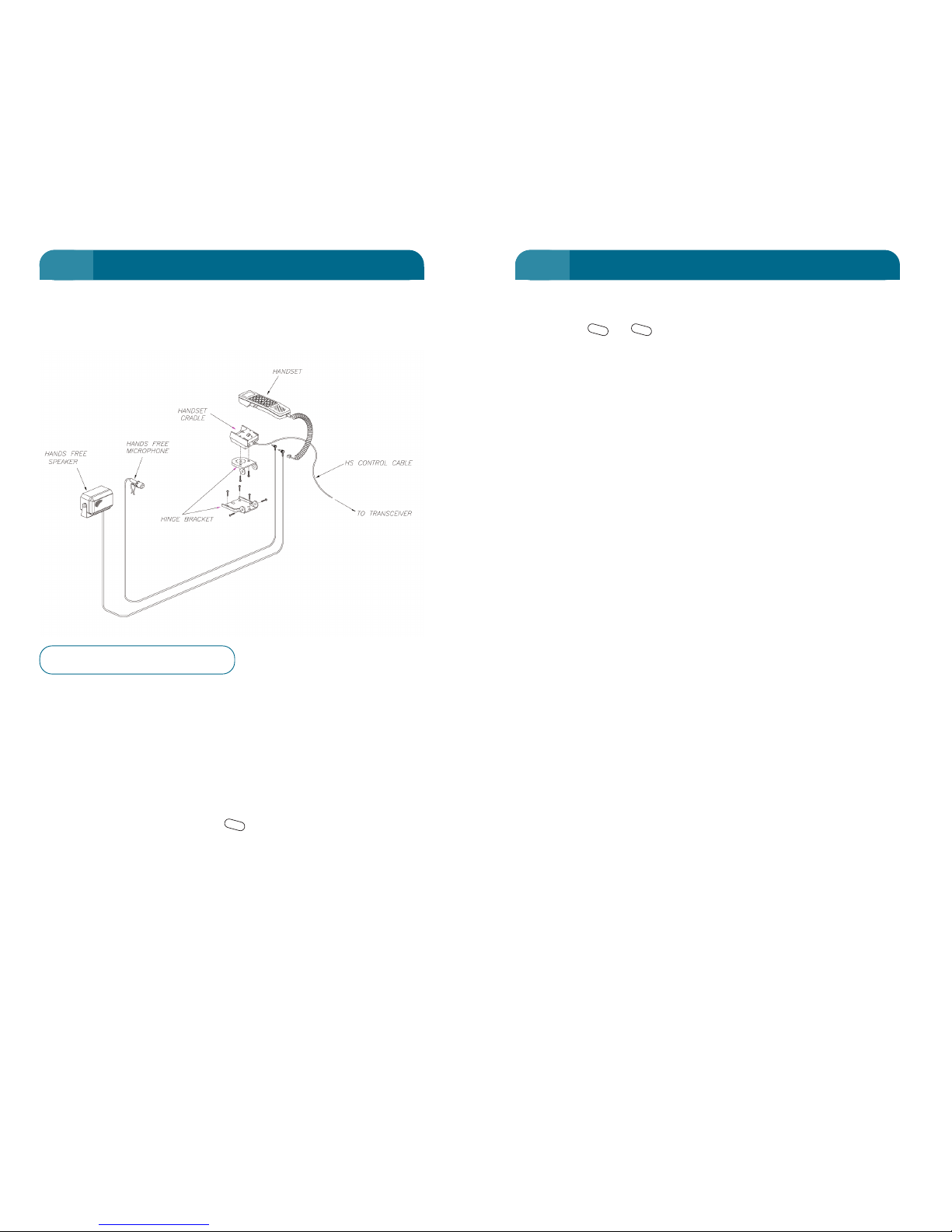
The handsfree adaptor consists of a handset cradle which has
connectors for a handsfree microphone and external speaker.
Handsfree operation is available when the microphone and
external speaker are connected to the cradle and the handset is
placed in the cradle.
Handsfree operation of the phone is the same as that for normal
handset operation, except for the following:
Muting
During Handsfree, the Mute key (held down) switches the
phone microphone On/Off when you are talking. The phone
automatically exits "Mic Mute" Mode when the phone is "offhook" from the cradle.
M
58
HANDSFREE
5 5
Figure 4 – Handsfree Configuration
Page 36

The Optus MobileSat S2 provides the ability to send pre-arranged
(coded) messages over the network without setting up a phone
call. This service requires setting up by your Service Provider
and the pre-coding of the messages at both source and
destination.
Each phone has the ability to send and receive up to 40 different
messages, each with its own attached 6 digit message code and
6 digit destination number. Each message is stored for user
display and has a maximum of 30 characters.
If you wish to say for example "Vehicle has stopped" or "Vehicle
is moving", set these messages in your memory, with a selected
code and destination number.
The destination will need to have the same messages installed
with the same codes, but not necessarily in the same memory
locations. The actual text of the message is NOT sent over the
network, only its code, so for the message to have any meaning,
the other end must know what the code means. The destination
may be another satellite telephone or a Dispatch Centre.
FCN 82 is used to recall a message for sending or for the editing
and storing of messages. Note that the destination number, is
not necessarily the number of the phone. Check with Optus.
SEND a Message
Phone must be in Standby mode (not In Use).
where XX is the memory
location of the message.
SNDXX
RCL
28
FCN
61
MESSAGING
System Operator Message (SysOp)
The System Operator Message is a message from the
Network Operator to all telephones on the system.
When a new message is received, the handset will beep twice
and display “System Message”. To view the message, press
. The or key can be used to view the second
page of the message.
Press once more to remove the message from the
screen.
This message is received at any time while a call is not in
progress. Any new message will over-write the previous
message. The most recent message can be viewed at any time
using FCN 81.
User Messages
The following message services need Optus to configure the
necessary Network Functions.
Emergency Message
Sent when emergency button (option) is pressed or FCN 83 is
selected.
In Call Messaging
This is a short message that can be received during a call and
displayed on the handset screen. The screen is erased at the
end of a call. This service may not be provided by the network.
Messaging
This system allows the sending and receiving of pre-arranged
(coded) messages, with the text for the message being
displayed from the memory when the code is received. A
description of this system is on the following pages.
CLR
-
+
CLR
60
SHORT TEXTS (MESSAGES)
5 5
Page 37

Summary (Messaging via the Optus MobileSat S2 Handset)
The following table is a summary of messaging via the Optus
MobileSat S2 handset.
Table 6: Message Type
Message
Direction
Stored upon
Type
(Relative to When
Reception
MobileSat S2)
SysOp In During Yes (last one
Standby only)
Distress Out During N/A
Standby
In Call Both During a call No
Coded Both During No
Standby
63
MESSAGING
RECEIVING a Message
• Push any key to view the message.
• If no matching code found then the message code number
will be displayed.
• (Hold) to view the message sender and other details.
Note: The Storage Location will show as ??) if the message code is Unknown.
FCN
62
MESSAGING
5 5
Message
Received
Flashing
Your Dinner
is Ready
Unknown
Message…
xxxxxx
(Message Code recognised) (Unknown Code)
xx)
fr xxxxxxx
msg xxxxxx
Storage Location
Message Sender
Message Code
Page 38
enter the GPS position as it will not be read from the GPS
navigational equipment.
Note: Optus does not presently support distress messaging.
EMERGENCY
Since Optus does not support distress messaging, you
should dial your usual emergency number 000.
GPS Messaging
The Optus MobileSat S2 can be configured to operate with
GPS equipment that can be either internal or external to the
transceiver. The Optus MobileSat S2 then reports this position
via a message sent ‘on request’ or periodically.
This type of message can be used to monitor operating zones
of Optus MobileSat S2 users, or for GPS based fleet
management systems.
Use of Mailboxes
The Optus MobileSat S2 has 32 mailboxes or memory
locations that are used by the system to store various
information parameters of the unit. The Optus MobileSat S2
will automatically store relevant information in predefined
mailboxes. You can also set various mailboxes via the DATA &
MAINTENANCE port using an external terminal and
appropriate communication software.
These mailboxes can be used in data acquisition applications
such as remote monitoring systems. Contact your Authorised
MobileSat Dealer for more information.
65
MESSAGING
Messaging via the DATA & MAINTENANCE Port
In order to send and receive messages via the DATA &
MAINTENANCE port of the Optus MobileSat S2, an external
terminal should be connected to the port which runs
appropriate communication software. The following table lists
the message types that can be sent and received from the
DATA & MAINTENANCE port and the direction of the message.
Messages Direction Relative to MOBILESAT S2
Normal both
One way both
SCADA in
Distress out
GPS out
Normal Message
This message allows 3 bytes of user information to be
transferred in either direction between the Optus MobileSat
system and the Optus MobileSat S2 transciever.
One-way Message
A One Way Message is the same as a Normal Message,
although the transmission of the message is not
acknowledged.
SCADA Message
This message is similar in structure to a Normal Message,
but the message is held at the earth station waiting for the
pre-determined Optus MobileSat S2 “wake up” time,
whereupon it is sent.
Distress Message
The Distress Message allows the earth station to know your
phone number and location (if the GPS navigational
equipment is connected to the unit). When a Distress Message
is sent via the DATA & MAINTENANCE port, the user must
64
MESSAGING
5 5
Page 39

Horn Alert
The Horn Alert function of the Optus MobileSat S2 allows you
to be away from the vehicle/installation but still be made
aware of incoming calls being received by sounding a horn or
flashing lights. The phone is kept on after ignition is turned off
so that the phone may still receive calls.
WARNING:
ENSURE THAT STATE LAWS PERMIT THE
OPERATION OF THE HORN ALERT FEATURE
BEFORE INSTALLATION.
Criteria for Horn alert
• Horn (and/or lights) wired to alert relay.
• FCN 32 turned ON.
• Vehicle Ignition is OFF (indicates vehicle unattended).
When horn alert is activated, the phone is kept powered up
even after the ignition is turned off. This option runs the risk
of flattening the vehicle battery.
To preserve the battery, the phone will turn itself off after a
period of time that can be set from the handset.
By toggling through the FCN 32 selections you can set the
phone to turn off after 1, 2, 3 ..... 10 hours.
For installation where battery drain is not a concern, selecting
the ‘On’ option inhibits the phone from shutting itself off.
A 2 minute test option is also a selection provided to test the
horn alert shutdown operation.
If there is a call in progress when the timer expires, then the
call will proceed but the phone will turn off when the call is
completed. The button can be used to turn off the phone
at any time.
The timer may be changed by selecting FCN 32 and entering a
new timer value.
PWR
67
CONFIGURATION ACCESSORIES
Ignition Switch Sensing
If this option is fitted and wired, the phone can be turned off
and on with the ignition switch depending on the setting of
Function 34. However if a call is in progress and the ignition is
switched OFF, the phone will stay ON until the end of the call.
Using Function 34, the Optus MobileSat S2 provides three
ignition sense options.
•Off
• Ignition Lock enable
• Ignition Lock disable.
Ignition Lock Off
The ignition or the key will turn On or Off the phone.
This mode behaves the same as the NEC S1 telephone
allowing a combination of ignition and key to control the
power to the phone.
Ignition Lock Enabled
The phone will not turn on unless the ignition is on. The phone
powers up with the ignition switch, or it can be turned on
using the key (as long as ignition is on). It can be
powered down using the key, but will switch on when the
ignition goes on again.
This feature stops the phone from powering up without
ignition being turned on, but allows the phone to be turned off
while the ignition is on.
Ignition Lock Disabled
The phone will only power on using the key. Ignition does
not affect the power status of the phone.
In this case the ignition is used only as a sense to enable the
horn alert function (ignition must be off for horn alert).
PWR
PWR
PWR
PWR
PWR
66
CONFIGURATION ACCESSORIES
5 5
Page 40
Thermal Control
The Optus MobileSat S2 transceiver can be configured to
provide an output to control the operation of a fan. If this line
is connected to a relay to control the power supply to the fan,
the S2 transceiver will turn the relay on when the internal
temperature of the unit crosses the predefined threshold. The
transceiver will turn off the relay when it has cooled to below
a predefined threshold.
This control line does not operate when the phone is powered
down.
RTS Control
The Optus MobileSat S2 can be powered on/off by the RS232
RTS line.
If (and only if) the unit is powered on by assertion of the RTS
line, then the phone will power down when the RTS line drops.
69
CONFIGURATION ACCESSORIES
The default horn alert setting is five seconds of alert tone (2
rings) before horn starts then the horn will sound for 5
seconds (2 rings). The handset will continue to ring after the
horn stops.
Setting Operation
Off Horn alert disabled.
1 hr Phone will stay on for 1 hr after ignition
turned off and ring horn if incoming call.
2 hr Phone will stay on for 2 hr after ignition
turned off and ring horn if incoming call.
10 hr Phone will stay on for 10 hr after ignition
turned off and ring horn if incoming call.
On Phone will not switch itself off and the horn
will be activated if incoming call.
2 min Test After ignition is turned off, the phone will
remain on for two minutes before turning
itself off. Any incoming calls will sound the
horn during this two minutes.
Note: Max Relay coil current is 150mAmps.
WARNING
Do not start the vehicle while the Optus MobileSat S2
is powered on. Sudden voltage fluctuations (due to
cranking) may damage the phone
68
CONFIGURATION ACCESSORIES
5 5
Page 41
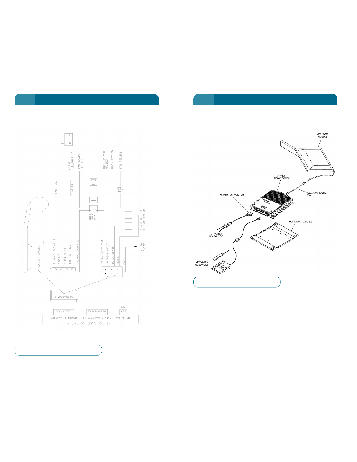
2-Wire Configuration
The Optus MobileSat S2 allows 2 wire phones to connect straight
into the front panel TEL & FAX port.
As this port can be used either for 2W telephone, or fax, it is
necessary to inform the Optus MobileSat S2 which type of call
(voice/fax) is being requested. A prefix digit can be used to do
this. Alternatively, by changing FCN 31 setting, you can configure
your installation so as not to require these prefix digits. (See
Placing a Call and "FCN 31: 2W TEL/FAX" on page 104 for
further details.)
However, if both an external 2W phone and fax machine are used
together in your installation, prefix digits will need to be used for
outgoing voice and fax calls.
71
CONFIGURATION ACCESSORIES
70
CONFIGURATION ACCESSORIES
5 5
Figure 5 – Fully Optioned Power Connection
Figure 6 – Remote Telephone Installation
Page 42
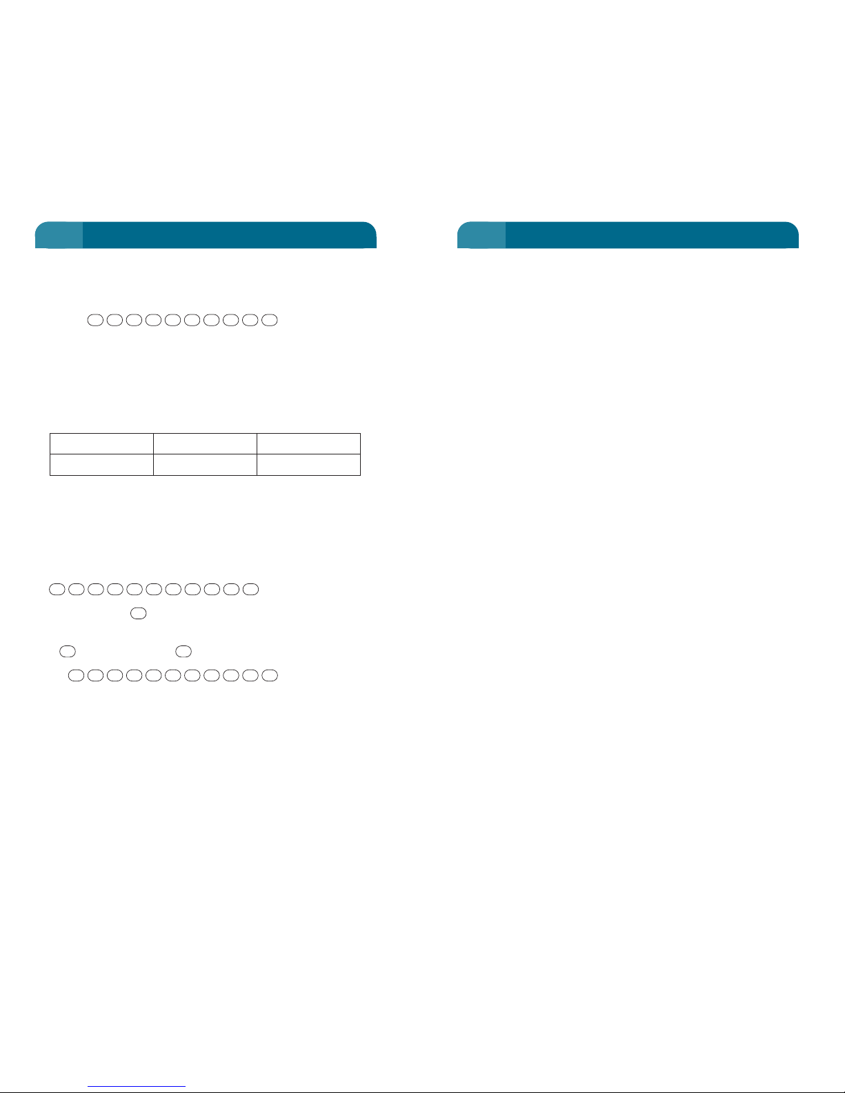
Prior to Commencement:
• Prior to purchasing a fax machine ask your Authorised
MobileSat Dealer for a list of compatible fax machines.
• When purchasing a fax machine, if possible, perform some
test faxes to commonly required terrestrial numbers. Use
different fax machines and choose the one that gives you
the best results.
• Ensure you properly understand the functionality of the TEL
& FAX port and FCN 31 and the effect it will have on
sending and receiving faxes. (Refer to Page 104).
• Ensure you fully understand how to send and receive faxes.
(Refer to Page 16 and Page 25).
• Ensure that FCN 35 is set to 2Wire On, without this faxes to
and from the Optus MobileSat S2 will not work. This
function is by default set to 2Wire On.
Hints for Sending:
• Optimise antenna tuning for best received signal strength.
• Ensure the fax machine is receiving dial tone from the
Optus MobileSat S2, without dial tone your faxes will not be
sent or received. This can be done by placing a standard
telephone handset on your 2W Fax cable to verify that dial
tone is indeed being emitted from the TEL & FAX port of the
Optus MobileSat S2.
• Ensure that the number you wish to dial is actually dialled
by checking the fax machine’s LCD display.
• If your fax machine will not transmit faxes, firstly re-check
all your fax machine configurations and options menus to
ensure all is correct (Note: Standard configuration
options/settings are optimal). Next try using your fax
machine over a terrestrial link to ensure its functionality.
There is a chance that the fax which you are using is not
compatible with the S2.
• For greater fax transmission success it is recommended
that standard or draft transmission modes be used. Do not
use Fine setting.
• Ensure fax is set for ECM = off (Error Correction Mode)
• In mobile vehicle fax transmissions, ensure power supply to
the Optus MobileSat S2 and fax machine is adequate.
73
CONFIGURATION ACCESSORIES
72
CONFIGURATION ACCESSORIES
TEL & FAX Prefix Digit
The TEL & FAX port can be dedicated to voice operation. In
this case the destination phone number need only be dialled.
eg dial .
Similarly, the TEL & FAX port can be dedicated to fax
operation and no prefix digit is required.
For configurations where a 2 Wire phone and fax machine are
connected to the TEL & FAX port, a prefix digit must be
entered before the phone number to set the call type.
Call Type 2 Wire phone Fax machine
Prefix Digit 12
Note: The Optus MobileSat S2 can only drive a 2 Wire load of 3 ren. Ensure
that combinations of 2 Wire equipment do not exceed 3 ren.
For example: If a fax and 2 Wire phone are connected to the
TEL & FAX port and the destination phone number is 03 9264
3050 the following buttons should be pressed when a fax is to
be sent:
.
The prefix digit sets the call type in the Optus MobileSat
S2 and is not sent to the earth station.
A would replace the if a 2 Wire voice call was required.
eg. .
Note: If a fax and 2W phone are connected to the TEL & FAX port there is a
risk that the fax will automatically answer an incoming voice call before the
handset is picked up. Ask your dealer to provide a Fax Switching cable so
that the fax does not ‘steal’ voice calls.
05034629301
21
2
05034629302
0503462930
5 5
Page 43

The GPS information can be read from the handset via FCN 24
which displays the longitude and latitude of the Optus
MobileSat S2 in degrees, hours and minutes. (See FCN24 on
Page 100)
External GPS
If the vehicle/vessel already has GPS equipment fitted, this
can be connected directly to the Optus MobileSat S2 via the
DATA & MAINTENANCE port. The external device should be
configured to output its data using the NMEA protocol at
4800bps for best results. Your Authorised MobileSat Dealer
can provide the customised cable for this application.
If the GPS does not update the Optus MobileSat S2, FCN 24 on
the handset will display "No GPS Position Available". The
current GPS information will be displayed after the Optus
MobileSat S2 has detected enough valid GPS data. If the Optus
MobileSat S2 cannot detect the external device, then the "No
GPS connected" will be displayed.
75
CONFIGURATION ACCESSORIES
• If possible, send all faxes in a static environment where the
Optus MobileSat S2 has a clear line of sight to the satellite
and is receiving adequate signal strength.
• When performing mobile fax calls try and send when on a
clear open road. Shadowing and loss of line of sight to the
satellite will greatly effect the success of your call.
• Transmission success when using your Optus MobileSat S2
to call another Optus MobileSat S2 while mobile is reduced
due to the increased delay in call setup time. For best
results ensure both telephones are static and have a clear
view to the satellite.
Hints for Receiving:
• Optimise antenna tuning for best received signal strength.
• Configure your fax machine to automatically answer the
incoming call on a minimum number of rings.
• If incoming calls are clearing prior to any fax reception,
disable all header and calling number identification
information on the receiving fax machine.
• Ensure that the sending party is dialling the correct
number for fax.
• If the received fax is illegible and unclear contact the
sender and instruct them to re-transmit the fax with
standard settings and in a static environment with a clear
view to the satellite.
• As a good rule of thumb, ensure your receiving fax machine
has sufficient paper to receive the incoming fax.
Internal GPS
Internal GPS consists of a GPS driver board within the Optus
MobileSat S2 transceiver. This printed circuit board once
connected to the GPS antenna and cable via the GPS
connector (SMA type) will report the global position of the
Optus MobileSat S2. Once the internal GPS has acquired
enough GPS satellite information it will report the position to
the Optus MobileSat S2 handset. It will also report GPS
information to a remote monitoring terminal if connected (See
Remote GPS Monitoring on next page).
74
CONFIGURATION ACCESSORIES
5 5
Page 44
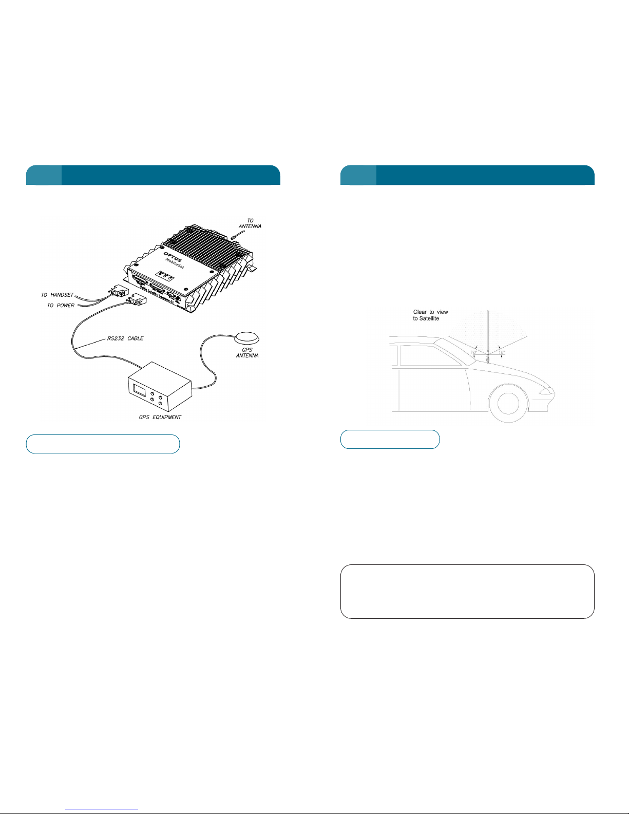
Unlike analogue or digital cellular phones, the Optus MobileSat
S2 Mobile Satellite Telephone is designed to work directly with
the Optus B-Series satellites, located above the equator, North
East of Australia.
For it to work correctly, there must be no physical obstruction
between your antenna and the satellite overhead. Generally
speaking, the satellite is in the north-east sky, in the direction of
the sun, mid morning. Your antenna should have a clear view in
all directions.
Possible reasons for an obstruction to a clear view of the
satellite are:
• Bridges overhead
• Large trucks alongside
• Antenna is at an angle from vertical
• Nearby buildings
• Inside buildings (unless the antenna is near a window
which has line of sight to the satellite)
• Medium tree cover does not prevent operation of the phone.
WARNING:
THE MAST ANTENNA CANNOT WITHSTAND
IMPACTS AT SPEED. CARE MUST BE TAKEN TO
AVOID DAMAGING THE MAST ANTENNA.
77
ANTENNA ADJUSTMENT
The port uses NMEA0183 protocol to store latitude and
longitude (only) in the standard GPS mailbox of the Optus
MobileSat S2. This can be polled by external parties to
determine the location of the Optus MobileSat S2. The
following NMEA commands are supported:
GGA: GPS fix data.
RMC: Recommended Minimum specific GPS Data.
Remote GPS Monitoring
When an inbuilt GPS is installed in the Optus MobileSat S2, a
monitor can be connected to the DATA & MAINTENANCE port
to view the GPS information. The connection is the same as
shown above except that the GPS position information comes
from within the Optus MobileSat S2.
76
CONFIGURATION ACCESSORIES
5 5
Figure – 7 External GPS Configuration
Figure 8 – Antenna Angle
Page 45

1. Select the handset FCN 91 screen to display the current
setting and RSSI level.
2. Adjust the antenna elevation to a value appropriate to your
location on Map 1, Page 81. This can be done by pressing
either the or key as appropriate on the side of the
handset. Alternately, use the key to increase the setting
or the key to decrease the elevations setting.
3. Monitor the RSSI level as the adjustments are made and
determine the elevation setting at the maximum received
signal. (RSSI display is only updated every 2 seconds). Stop
adjusting when the maximum RSSI is reached.
4. Exit FCN 91 using the key.
Note: The antenna must be kept clean to maximise the transmit and receive
signal strength.
It is possible to fine tune the antenna while in a call.
When to RE-ADJUST
While moving your vehicle within local regions, it is unlikely that
your antenna will need adjustment, however:
• If signal strength appears to have dropped, and no
obstructions are obvious, it is recommended that an
adjustment be made. Always check that the antenna is
vertical.
• As your vehicle moves across Australia from Townsville to
Perth, it is recommended that changes are made as
necessary. Refer to Map 1 on Page 81.
• Moving from Melbourne to Broome on a direct route would
require no adjustment.
• Re-adjustment can be made during a call, but to monitor
RSSI the party at the other end must be talking.
CLR
*
#
-
+
79
MAST ANTENNA ADJUSTMENT
Motorised Mast Antenna
The Motorised Mast antenna must be calibrated and adjusted
correctly for reliable communications. It should have been set
correctly for your location when it was installed, however if
adjustment is necessary the following instructions are provided.
CALIBRATION
The calibration process (FCN 92) winds the antenna from the
lowest setting right through to the maximum setting to
determine the size of each step for handset adjustment. Once
the antenna has driven the antenna through the full adjustment
scale, the motor will drive the antenna to the last known
elevation setting (the default elevation setting is 45 degrees). The
calibration of the mast antenna should take less than 20
seconds. At the completion of the calibration process, the screen
allows adjustment of the antenna using the or keys.
Calibration of the antenna is required every six months (at a
minimum) to ensure the correct control of the antenna by the
transceiver. Changing between different mast antennae requires
recalibration of the new mast antenna.
ANTENNA TRACKING
After a mast antenna is calibrated, the Optus MobileSat S2
automatic antenna tracking is enabled (ie Track On). The
tracking status is configured using FCN 93. This antenna
tracking instructs the Optus MobileSat S2 to periodically test the
received signal level, and adjusts the elevation angle setting of
the antenna automatically to optimise its setting. Auto tracking
will not occur during a call.
ADJUSTMENT
The Optus MobileSat S2 Motorised Mast antenna is incrementally
adjusted from the handset controls using FCN 91. There are no
physical adjustments to be made to the antenna itself.
The strength of the signal is shown on the handset RSSI
(Received Signal Strength Indicator) display.
When adjusting the antenna, it is important to have the vehicle
on a flat, fixed position with the antenna mounted vertically.
-
+
78
MOBILESAT ANTENNA
5 5
Page 46

MAP 1
MAP 2
AREA OF COVERAGE
81
ANTENNA ADJUSTMENT
Fixed Site Installation
Where a motorised mast antenna is used in a fixed site
installation, it is possible to enhance the performance of the
antenna by pointing the antenna directly at the satellite.
With the elevation adjustment set to a maximum, the antenna
beam behaves similar to a torch beam where the radiation
pattern fires out the end of the mast (End Fire Method).
The antenna should be mounted in a fixed position when the
maximum RSSI is determined. In this configuration, the gain of
the antenna is improved.
Emergency Operation
In an emergency situation where the vehicle cannot support the
motorised mast antenna in a vertical position (i.e: the vehicle has
rolled on its side), it is possible to dismount the antenna and
hold it by the spring pointing toward the satellite. The antenna
should be tuned to the maximum elevation (70º tuning for End
Fire Method) for the duration of the call. While the radiation
pattern is pointed to the end of the antenna, it is safe for a
person to hold the antenna by the spring.
80
MAST ANTENNA ADJUSTMENT
5 5
ELEVATION NUMBERS
Adelaide 43
Alice Springs 50
Birdsville 52
Bourke 52
Brisbane 58
Broome 43
Canberra 48
Darwin 53
Eucla 41
Gove 59
Hobart 39
Kalgoorlie 35
Melbourne 44
Mt. Isa 56
Normanton 60
Perth 30
Port Hedland 38
Portland 42
Rockhampton 62
Sydney 50
Townsville 63
Woomera 46
Page 47

Dome Antenna
The Dome antenna is a highly versatile antenna and can be
utilised in a host of applications. It is suitable for vehicular
(trucks, cars), fixed site, and marine applications.
The antenna operates autonomously and requires no user
intervention or calibration. The antenna uses a simple
mechanical steering mechanism to maintain tracking of the
satellite. Upon initial power up it simply requires a brief
initialisation period to acquire the satellite's position. The
antenna steering is self-recovering after shadowing effects or
loss of signal, and will maintain accurate pointing at the satellite
at all other times.
Note: The handset of the Optus MobileSat S2 does not control the
functionality of the Dome antenna, the antenna operates autonomously.
Installation of the Dome antenna requires one single coaxial
cable from the transceiver to the antenna's base. The antenna
can be mounted on its own or with its magnetic mount
(purchased separately). There is also a pole mount option,
contact your Authorised MobileSat dealer for further
information.
The Dome antenna on its own has four screw holes on the base
plate, these can be used to permanently affix the antenna to flat
surfaces. Alternatively, the magnetic mount can be used for
temporary installations or for installations where holes are
undesirable. For best results the magnetic mount should be
installed on a clean flat metallic surface. The magnetic mount
has its limits and the following warnings should be noted. Do not
drive at speeds greater than 200kph or greater than 100kph into
a 100kph head wind or similar combinations. These speeds can
cause the magnetic mount to dislodge*.
Note: Optus recommends that for best results, the antenna be mounted on a
horizontal flat surface, and that there are no obstructions to the antenna's
line of sight to the satellite at all times.
83
ANTENNA ADJUSTMENT
Planar Antenna Adjustment
The planar antenna is intended for fixed site or itinerant use. Its
adjustment involves pointing the antenna’s radiating face toward
the satellite to get the maximum RSSI reading. This is best
achieved using the following steps:
Adjust the elevation angle of the radiating face of the antenna to
the designated angle shown in Map 1 for the geographical
position of the antenna. Set the radiating face of the antenna to
point in a North Easterly direction.
Observe the handset signal strength number and swivel the
direction of the radiating face in the horizontal plane until the
maximum signal level is achieved. Fix the antenna mount in this
direction where this maxima is determined. (Note that the RSSI
indicator of the handset updates every 2 seconds).
Observe the handset signal strength numbers to adjust the
angle of the radiating face of the antenna until the maximum
signal strength is achieved. Fix the antenna elevation in this
position. (Note that the RSSI indicator of the handset updates
every 2 seconds).
No further adjustment is required unless the antenna is moved
from the initial position.
Marine Antenna Adjustment
The steering of the Marine Antenna is controlled by the
transceiver and adjustment by the user is not required for
normal operation.
After the initial calibration of the antenna on installation, the
transceiver will steer the antenna from that point on.
Note: If any structural or appliance changes occur to the installation, the
calibration procedure should be repeated.
82
ANTENNA ADJUSTMENT
5 5
Page 48
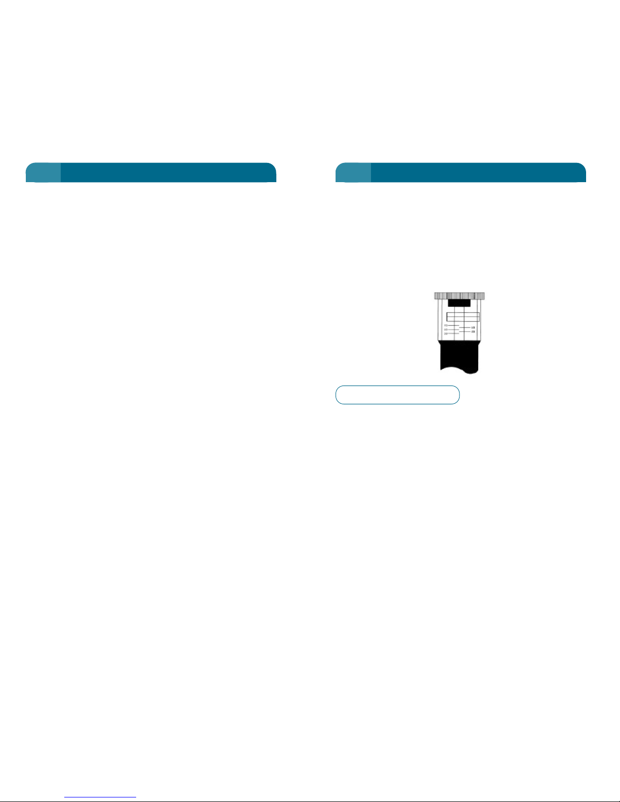
MANUALLY ADJUSTED MAST ANTENNA
In the case of the Manually Adjusted Mast antenna, the handset
FCN 91 will not adjust the antenna elevation. Rotating the
adjustment knob on the top of the antenna sets the elevation
angle of the antenna. It would have been correctly adjusted for
your location during its installation, however if the signal
strength has dropped noticeably, perform the following
procedure to adjust the antenna.
1. Ensure that the antenna is vertical.
2. From the map on Page 81, determine the elevation setting
for your current geographic location.
3. Rotate the adjustment knob (milled edge wheel at the top
of the antenna) until the indicator in the adjustment window
aligns with the elevation marker from the map
(eg: Broome = 43 degrees).
4. Read the handset display to determine your signal
strength.
5. Adjust the knob by an eighth of a turn in elevation to
determine your maximum received signal setting. The
signal strength may remain at a maximum for several
adjustments of elevation.
6. Increase the elevation setting of the antenna until the RSSI
numeric value drops 1 or 2 below the maximum.
7. At this setting, calls should be attempted in both directions.
85
ANTENNA ADJUSTMENT
*Optus does not accept responsibility for any damages or
injuries, whether direct or indirect, that the magnetic mount
installation may cause. Optus will not warrant any damages
caused to the antenna in the event that the magnetic mount
comes free during use.
Received Signal Display Modes (All Antennas)
The received signal display on the handset display can be viewed
in two modes:
• RSSI (Received Signal Strength Indication), and
• RSNR (Received Signal to Noise Ratio)
To toggle between the two modes, simply press the FCN button
followed by the MUTE button located on the side of the handset.
The default mode for the Optus MobileSat S2 display is RSSI. The
Optus MobileSat S2 will remember the user’s last received
signal display mode on subsequent power ups from the handset.
The RSNR display mode is distinguishable from the RSSI display
mode by a small ‘sr’ character located to the right of the
numerical received signal display.
Both use a scale of 1-20 where the higher value represents
better operation.
84
ANTENNA ADJUSTMENT
5 5
Figure 9 – Mast Adjustment Knob
Page 49

SPECIAL Functions
Some functions are relevant only during digit entry mode.
is used to provide a "Wait" between number sets in a
single sequence. Refer to the chapter on NUMBER SETS on
Page 54. It shows as a "w" in the phone number. This function
only operates when entering a phone number.
provides a “Pause” in number sets (period defined by
Earth Station). It shows as a "p" in the phone number on the
display. Refer to Page 54. This function only operates when
entering a phone number.
starts Repeat Dial mode. Refer to Page 44.
(Hold) during digit entry will show any higher digits of a
phone number that are not already on the screen.
will toggle between RSSI and RSNR display while
viewing the Standby screen.
will terminate a fax or data call that is in progress.
Call Control
While inside a Function, a call can be answered by pushing
any key except or , however the Function will be
exited without saving any changes.
If a Function is entered after a call has commenced the
key will hang up the call and exit the function ignoring any
changes not saved.
If the other party hangs up, the function will be exited in the
same manner.
END
ENDPWR
ENDFCN
M
FCN
FCN
SND
FCN
0
FCN
9
FCN
87
FUNCTIONS
The purpose of the key is to provide more control than a
single key can provide. Using the key and associated menu
selection or numbers, many extra features can be controlled.
If you know the function required, (they are all 2 digit numbers),
you can go directly to that function. If however, you wish to scan
the available menu options, push the key then step through
the options with the or keys using or to make
your selection.
Most function sets may be selected while in a call or in the
Standby display.
The setting of each function will remain even if the phone is
powered off and on again.
Settings will be lost if phone power is interrupted without
powering down using PWR button on the handset.
MENU Selection
• Primary Menus
to enter the primary menu at the Function 1 group.
/ or / to scroll up or down through the primary
menu. The Primary Menu heading will be displayed.
, to enter the Secondary Menus with the number
flashing.
If you are in Primary Menu 6 or 7 you will be asked for the
Confidential Code.
• Secondary Menus
/ or / to scroll up or down through the
secondary menu.
or to enter the Function with the number flashing.
DIRECT Entry
where XX is the function number required.
XX
FCN
SND
STO
*
#
-
+
SND
STO
*
#
-
+
FCN
SND
STO
-
+
FCN
FCN
FCN
86
FUNCTIONS
6 6
Page 50
89
FUNCTIONS
EXIT a Function
(Hold). Holding will always exit (without saving) a
function display and return to the previous screen.
Locked Functions
When entering any function from the Primary Menu with 6 or
7, a screen requests the Confidential Code. Refer to Page 124.
CLRCLR
88
FUNCTIONS
6 6
FCN 1
Time
Functions
FCN 2
Unit Status
Functions
FCN 3
Terminal
Option/Setup
FCN 4
Tone
Functions
FCN 5
Screen
Functions
FCN 6
Lock
Functions
FCN 7
Clearing
Functions
FCN 8
Message/CUG
Functions
FCN 9
Antenna
Functions
1
Call Time
FCN 11
Own Number
FCN 21
2W Tel/Fax
FCN 31
Ring Volume
FCN 41
Backlight
FCN 51
Lock Code
Set
FCN 61
Time Clear
FCN 71
Recall Sys
Op Msg
FCN 81
Antenna
Adjust
FCN 91
FCN 0 and FCN 9 are used during digit
entry give a pause or wait digit.
2
Total Call
Time
FCN 12
SW Version/
ESN
FCN 22
Horn
FCN 32
Ring Pitch
FCN 42
Contrast
FCN 52
Lock Mode
FCN 62
Clear Last
Numbers
FCN 72
Messaging
FCN 82
Antenna
Calibrate
FCN 92
3
Outgoing Call
Time
FCN 13
Zone/Class
FCN 23
Auto Answer
FCN 33
Ring
Cadence
FCN 43
Wakeup
Screen
FCN 53
Auto Lock
Enable
FCN 63
Number
Prefix
FCN 73
Distress
Message
FCN 83*
Antenna
Tracking
FCN 93
4
Call Time
Beeps
FCN 14
GPS Location
FCN 24
Ignition Lock
FCN 34
Tone Volume
FCN 44
Call Credit
FCN 64
Memory
Clear
FCN 74
Predefined
CUGs
FCN 84
5
Clock Set
FCN 15
Volts/Temp
FCN 25
2-Wire
Enable
FCN 35
Key Beep
Enable
FCN 45
Network
FCN 65
Edit CUG
Tex t
FCN 85
6
Clock Display
FCN 16
LED Display
FCN 26
System ID
Download
FCN 36
DTMF Tone
FCN 46
Lock Msg
Tex t
FCN 66
7
Alarm Log
FCN 27
Handsfree
Sensitivity
FCN 37
8 9
Primary Menu Secondary Menu
FCN (Hold) = View Hidden Digits
FCN SND = Repeat Dial
FCN (Mute) = Toggle RSSI/RSNR
FCN END = Terminate a current fax or
data call from handset
*Optus does not support this function.
Page 51
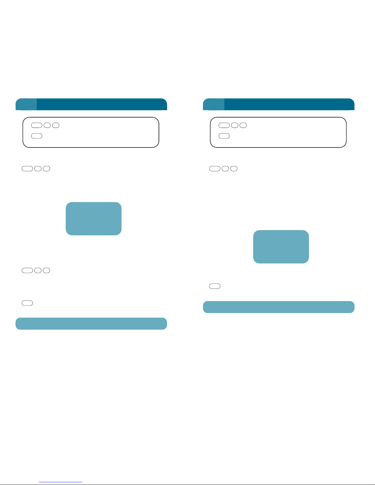
91
FCN 12: TOTAL CONNECT TIME
90
FCN 11: CALL TIME
Call Time
EXIT
CLR
11
FCN
View Elapsed Time of Last Completed Call (Length of Call)
Last call time will be displayed in minutes and
seconds.
Each call is calculated from "In Use" until "Standby" or "No
Service".
Depending on call charging method, this may not be directly
related to your account time.
View Elapsed Time During a Call
Press at any time during a call. Call elapsed time
will be displayed in minutes and seconds, and will update as
call time progresses.
EXIT
Return to previous screen.
This time is reset when the next call is connected.
CLR
11
FCN
11
FCN
FCN 11
Call Time
05m 15s
Call Connect Time
EXIT
CLR
21
FCN
Review Total Connection Time
The accumulated call time from this phone will
be displayed in hours and minutes.
Each call is calculated from "In Use" until "Standby" or "No
Service".
The time includes both outgoing and incoming calls.
Depending on call charging method, this may not be directly
related to your account time.
EXIT
Return to previous screen.
To clear the total time, refer to FCN 71.
CLR
21
FCN
6 6
FCN 12
Total Time
999h 45m
Page 52
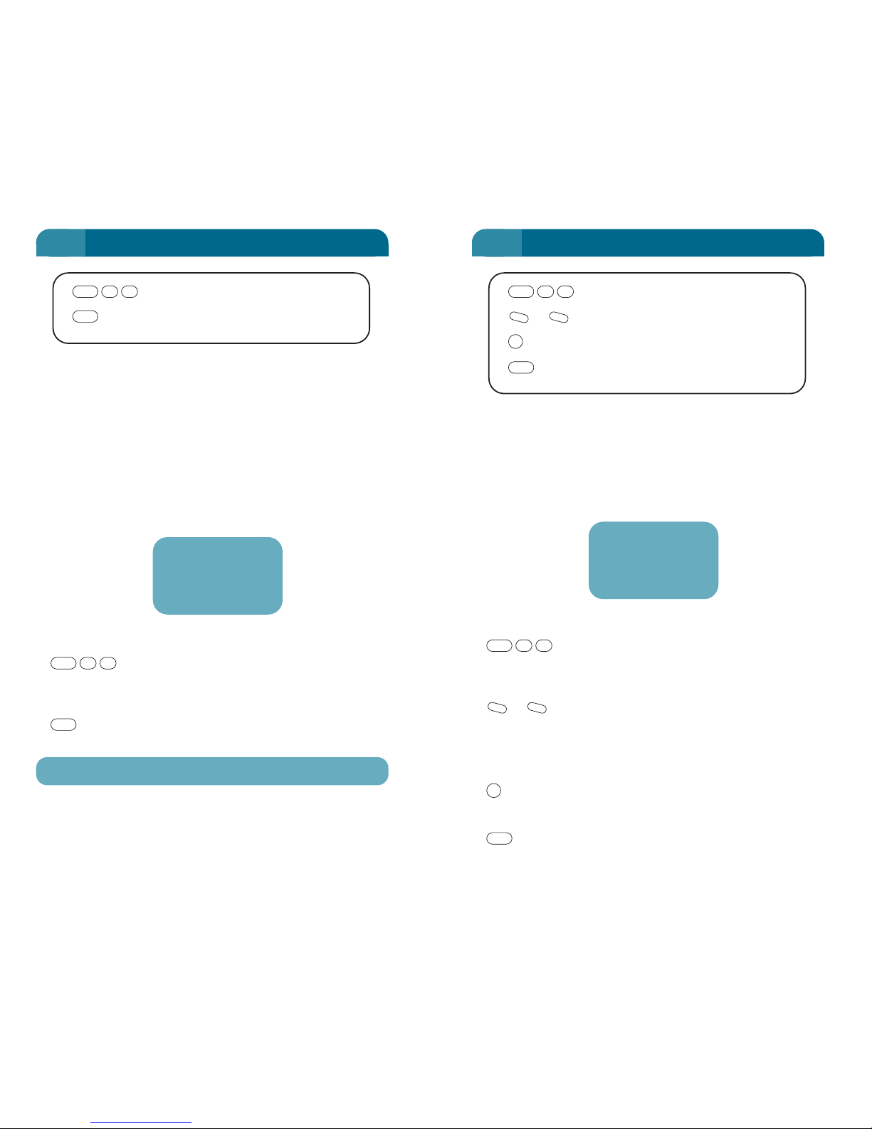
When the call time beeps mode is activated, timing tones sound
during conversation to inform your air time use. A single "beep"
sounds 10 seconds before the end of each minute. A double
"beep" signals the end of each minute.
Note: This function operates differently if the Call Credit facility (FCN 64) is
activated.
DISPLAY Current status
The phone display shows whether Call Time
Beeps are On or Off.
Toggle the status
or will toggle the mode "On" and "Off".
The display will start flashing, indicating that this status has
been changed, but has not been saved.
Save and EXIT
will set and save the new value, then EXIT the function.
EXIT without saving.
Return to the previous screen.
CLR
STO
-
+
41
FCN
93
FCN 14: CALL TIME BEEPS
92
FCN 13: OUTGOING CALL TIME
Outgoing Call Time
EXIT
CLR
31
FCN
Call Time Beeps
or Change Status
SAVE and EXIT
EXIT without saving
CLR
STO
-
+
41
FCN
Review Total Outgoing Call Time
The accumulated outgoing call time from this phone will be
displayed in hours and minutes.
Each call is calculated from “In Use” until “Standby” or “No
Service”.
Depending on call charging method, this may not be directly
related to your account time.
This display can be monitored while a call is in progress.
Display Outgoing Call Time
The outgoing call time will be displayed on the
handset.
EXIT
Return to previous screen.
To reset the outgoing call time, refer to FCN 71.
CLR
31
FCN
6 6
FCN 13
O/G Time
451h 38m
FCN 14
Time Beeps
On
Page 53
You may set whether the clock time display is to be continuously
displayed while the telephone is in Standby mode.
Display Current Setting
to display the clock status.
The status will be either "On" or "Off".
Change Status
or or or will toggle the status.
The display starts flashing indicating that this status has been
changed but not saved.
Save and EXIT
Save the setting and EXIT.
EXIT without saving
Return to the previous screen.
CLR
STO
*
#
-
+
61
FCN
95
FCN 16: CLOCK DISPLAY
Set the internal CLOCK and DATE
to enter the clock set mode.
The HOUR will flash, indicating that this is about to be
changed.
or or or to set the new value.
to save and step on to minutes, which will now flash.
The order the time and date is set is as follows
HOUR MINUTE DATE MONTH YEAR
Hint
To step on without changing, just push .
If you make a mistake, press (Momentarily – less than
1 second) to backspace to the previous item.
As the date is changed, the day of the week is set automatically.
Leap year is calculated automatically.
EXIT
after setting YEAR to save setting and EXIT or,
(Hold) for 1 second for
immediate EXIT without saving.
If any value is not stored, when is
held to EXIT, the old value is
left unchanged.
CLR
CLR
STO
CLR
STO
STO
*
#
-
+
51
FCN
FCN 15: CLOCK SET
Clock Set
or Change Status
SAVE and EXIT
(Momentarily) Step Back
(Hold) EXIT without saving
CLR
CLR
STO
-
+
51
FCN
Clock Display
or Change Status
SAVE and EXIT
EXIT without saving
CLR
STO
-
+
61
FCN
FCN 15
9:32a Fri
7 Oct ’96
94
6 6
FCN 16
Clock Disp
On
Flashing when
changed
Page 54
EXIT without saving
(Hold) Return to previous screen.
To Modify your Own Numbers
to display your own phone number
(Use / to select the number to modify).
, or digit key to begin editing.
Enter number from keypad.
(momentarily) to correct errors.
It is not possible to switch between own phone number, data
number or fax number while in edit mode.
SAVE and EXIT
A message saying "Stored" will be displayed for about 5
seconds, before returning to Standby screen. (This can be
cleared immediately by pressing the key.)
EXIT without saving
(Hold) Return to previous screen.
Note: The number cannot be changed whilst the phone is in Partial or Full
Lock.
CLR
CLR
STO
CLR
STO
SND
-
+
12
FCN
CLR
97
FCN 21: OWN NUMBER
This function allows you to hold your own phone number for easy
reference. The number stored here is not used by the network
operations. If the incorrect number is loaded the phone will still
work using the network allocated number, i.e. this number is
only kept here for your information.
The Optus MobileSat S2 may have different numbers for voice,
fax and data calls. From the Own Number screen, it is possible
to record your allocated fax number and data number.
To View Your Own Telephone Number:
to display your own phone number. To view the
rest of any long number, press or and then press
(hold) for over one second.
/ Scroll to own fax number
or own data number.
Editing these numbers is the same as
editing your own phone number.
-
+
FCN
SND
STO
12
FCN
96
FCN 21: OWN NUMBER
6 6
Own Number
or Toggle between voice/fax/
data number
To edit selection
… New Number
SAVE and EXIT
(Hold) EXIT without saving
CLR
STO
XXX
STO
-
+
12
FCN
FCN 21
Own Number
0145107145
Page 55
This function allows you to read the configuration parameters of
the Optus MobileSat S2 terminal. The read-only parameters are
Zone, Class, Priority and Quality.
These parameters affect the satellite power used to make the
call, and can be monitored by Optus at any time.
Read Configuration Parameters:
The display of the
parameters is in an abbreviated
format where:
Z – Zone (range 0-3)
C – Class (range 1-4)
P – Priority (range 0-3)
Q – Quality (range 0-3)
EXIT
Return to the previous screen.
CLR
32
FCN
99
FCN 23: ZONE/CLASS/PRIORITY
This function allows you to immediately determine what software
version is loaded inside the S2 transceiver unit. Each unit is
uniquely identified by its Electronic Serial Number (ESN). The
ESN will be displayed as a decimal number with a maximum of
fourteen characters. This function provides a read-only display.
Supplementary pages provide:
• GPS configuration
• HPA software version
• Antenna software version and serial number.
Review Software Version and ESN
The software version
and the ESN number of the unit
will be displayed. / to
toggle through the supplementary
pages.
EXIT
Return to the previous screen.
CLR
-
+
22
FCN
98
FCN 22: SOFTWARE VERSION/ESN
6 6
Software Version/ESN
EXIT
CLR
22
FCN
Zone/Class/Priority
EXIT
CLR
3
2
FCN
Ver 37
ESN : 0123
4567890123
FCN 23
SYS_CONFIG
Z2C1P3Q2
Page 56
This function displays the current position of the Optus
MobileSat S2 as derived from the GPS driver inside the S2
transceiver or an external GPS device. This is a read-only
display.
This information is stored in a mailbox within the memory. It is
sent with the distress message packet whenever this facility is
activated.
If no GPS driver is installed, the mailbox will be loaded with zero
values for latitude and longitude. An external GPS device may
be connected to the Optus MobileSat S2 to update the mailbox.
See page 75.
This screen will flash every 10 seconds to indicate that an update
has occurred. A supplementery page shows the speed and
heading information.
Read GPS Location
The GPS Location will
display the latitude and longitude
in degrees, minutes and seconds.
/ to toggle to
supplementery page.
EXIT
(Hold) Return to previous screen.
CLR
-
+
42
FCN
100
FCN 24: GPS LOCATION
6
GPS Location
EXIT
CLR
42
FCN
Position:
0º 0’ 0S
0º 0’ 0E
FCN 25: VOLT/TEMP
6
101
This function displays the voltage supply level (as measured by
the unit) and the internal temperature of the Base Assembly
unit. The second page displays the temperature of the HPA unit
and also the AFC offset. This is a read-only screen, that is
updated every 2 seconds. The software updates the supply
voltage measurement every 2 seconds, but the temperature is
only updated every 20 seconds.
A voltmeter or thermometer should be used if these parameters
are to be monitored for a length of time.
Read Unit Voltage and Temperature
The Voltage and
Temperature of the unit will be
displayed.
or to toggle between the
two pages of information.
EXIT
Return to previous screen.
Protective Shutdown
The Optus MobileSat S2 powers
down when the internal
temperature reaches 70°C, or
goes below -15°C (warning at
65°C, -10°C).
The Optus MobileSat S2 powers
down when the (averaged) supply
voltage drops to 10.5 Volts, or goes over 32V for more than 2
seconds.
Warning displays appear on the handset if the excess is
gradual.
CLR
-
+
52
FCN
Volt/Temp
EXIT
CLR
52
FCN
FCN 25
Volt 13.6 V
Base 33ºC
FCN 25
AFC +002Hz
HPA 28ºC
Page 57
The Optus MobileSat S2 always logs alarms or events that are
flagged within the software. You can recall the log using this
function to report a history to an Authorised MobileSat dealer.
The read-only screen contains the log number, the time and
date of the event/alarm and an indicator of the nature of the
event or alarm.
An event is distinguished by an ‘EV’ on the bottom line, where an
alarm displays ‘AL’. Events occur due to protocol failures over
the air, while alarms point to disturbances in the Optus
MobileSat S2 transceiver.
This information in this log is only useful to the Dealer or Optus
for fault analysis, but you may be asked for it when reporting a
fault.
Display Log entries
The event/alarm entry
is displayed.
To Scroll through Log
or Scrolls through the log
by log number.
EXIT
Return to the previous screen.
CLR
-
+
72
FCN
FCN 27: EVENT/ALARM LOG
6
103
This function copies the transceiver LED indicators (on top cover
of Base Assembly) to the handset.
The second row of the display indicates:
GEN = General
CH = Channel
SIG = Signal
The third row of the display shows the colour of the LED (G =
Green, O = Orange, R = Red, a blank means the LED is off).
Refer to page 176.
To View LED Display
The handset
representation of the LED
indicators will be displayed.
Changes in the LED display are
updated regularly.
EXIT
Return to previous screen.
CLR
62
FCN
FCN 26: LED DISPLAY
6
102
LED Display
EXIT
CLR
62
FCN
Event/Alarm log
or Toggle through log entries
EXIT
CLR
-
+
72
FCN
STATUS
GEN CH SIG
GOG
005) 16:15
11 Jun 1997
AL: 23 HW
Page 58
2W TEL/FAX On/Off
This configuration only allows voice
calls to or from the 2 Wire port. A 2W
phone, or cordless phone can be
used instead of the handset to make
and receive calls. Incoming voice
calls will ring the handset and the 2W
phone Incoming fax calls will be
rejected.
2W TEL/FAX Off/On
This configuration only allows fax
calls to or from the 2 Wire port. A fax
machine is used to send and receive
faxes. Incoming voice calls will ring
the handset only. Incoming fax calls
will be answered by the fax machine.
2W TEL/FAX On/On
This configuration allows both voice
and fax calls to or from the 2 Wire
port. A prefix digit must be used for
outgoing calls to inform the Optus
MobileSat S2 what call type is
proceeding. Incoming voice calls will
ring the handset and the 2 wire port.
Incoming fax calls will ring only the 2
Wire device/s.
Prefix digit “1” for voice calls
Prefix digit “2” for fax calls
(See page 71 for more details.)
SAVE and EXIT
Save the setting and EXIT.
EXIT without saving
Return to previous screen.
CLR
STO
FCN 31: 2W TEL/FAX
6
105
This function allows control over the operation of the 2 Wire port
of the Optus MobileSat S2. It can enable the 2 Wire port to be
used for either voice calls only or fax calls only, or both voice and
fax calls.
The three configurations together with instructions on their use
are described below.
Note: FCN 35 must be set to enable 2W operation for FCN 31 to operation
correctly.
Display Current Setting
to display the current 2W TEL&FAX port status of
the unit.
Change Status
or will toggle the status. The display will start
flashing, indicating that the status has been changed but not
saved.
The three FCN 31 settings are:
(i) 2W TEL/FAX On/Off (2W phone only)
(ii) 2W TEL/FAX Off/On (2W fax only)
(iii) 2W TEL/FAX On/On (2W phone plus fax)
-
+
13
FCN
FCN 31: 2W TEL/FAX
6
104
2W TEL/FAX
or Change Status
SAVE and EXIT
EXIT without saving
CLR
STO
-
+
13
FCN
FCN 31
2W TEL/FAX
On/Off
FCN 31
2W TEL/FAX
Off/On
FCN 31
2W TEL/FAX
On/On
Page 59
If the function is activated, the
Standby screen will display the
letters ‘HA’ to indicate that the Horn
Alert function is ON
Refer to page 67.
FCN 32: HORN ALERT
6
107
When the phone is provided with the horn alert accessory, the
car horn and/or lights can sound or flash when the phone rings.
WARNING:
ENSURE THAT STATE LAWS PERMIT THE
OPERATION OF THE HORN ALERT FEATURE
BEFORE INSTALLATION.
Display Current Status
to display the current Horn Alert mode.
Change Status
or to toggle the status.
OFF, 1,2....10, ON, 2min Test.
The display will start flashing to
indicate that the status has been
changed but has yet to be saved.
SAVE and EXIT
Save the setting and EXIT.
EXIT without saving
Return to previous screen.
CLR
STO
-
+
23
FCN
FCN 32: HORN ALERT
6
106
Horn Alert
or Change Status
SAVE and EXIT
EXIT without saving
CLR
STO
-
+
23
FCN
FCN 32
Horn Alert
Off
9:20pm
9 HA
Standby
Page 60
The Optus MobileSat S2 provides three options for the operation
of the ignition control; Off, Lock enable, and Lock disable.
Off: The key can override ignition control.
Enable: The phone will not power on unless the ignition is on.
Disable: The ignition control is always ignored, even though it
may be wired in
For more details refer to Advanced Settings, page 66.
Display Ignition Lock setting
to display the current mode.
Change Mode
or Toggles between “Off”, “Enable” and “Disable”.
The display flashes, showing the
mode has been changed but not
saved.
SAVE and EXIT
Save the setting and EXIT.
EXIT without saving
Return to previous screen.
CLR
STO
-
+
43
FCN
PWR
FCN 34: IGNITION LOCK
6
109
When the phone has the external microphone connected, it is
possible for it to automatically answer the phone, allowing
"handsfree" operation.
Criteria for automatic answering
• Handsfree microphone plugged in.
• Handset is in the cradle.
• Phone is turned ON.
• FCN 33 (this function) turned ON.
• Vehicle Ignition is ON (or accessory position).
The call is automatically answered after 5 seconds (2 rings).
(Default setting).
Display current Mode
to display the current mode.
Change Mode
or will toggle the mode "On" and "Off".
The display will flash, showing that
the mode has been changed but
has not been saved.
SAVE and EXIT
Save the setting and EXIT.
EXIT without saving
Return to previous screen.
CLR
STO
-
+
33
FCN
FCN 33: AUTOMATIC ANSWER
6
108
Auto Answer
or Change Status
SAVE and EXIT
EXIT without saving
CLR
STO
-
+
33
FCN
Ignition Lock
or Change Status
SAVE and EXIT
EXIT without saving
CLR
STO
-
+
43
FCN
FCN 33
Auto. Ans
Off
FCN 34
Ign Lock
Off
Page 61
In discussion with an operator from
Optus, it may be agreed to send new
Identification Codes to your phone.
FCN 36 allows the phone user to
accept those new codes.
This message appears, possibly
several times during the call to the
operator, and you will be instructed
to press .
Do not press the function until
instructed and do not terminate the
call without operator permission, as
a partial transfer could "lock up" the phone, requiring it to be
returned to the dealer for service.
• At the completion of the call, the phone automatically powers
down (switch off). You may immediately restart.
If you decide not to accept the changes or as instructed by the
operator, use the (Hold) before the function, to clear the
changes.
WARNING:
DO NOT TURN OFF THE PHONE DURING THE CALL
TO THE OPERATOR FOR THE ID DOWNLOAD,
AS THIS MAY ALSO CORRUPT THE
IDENTIFICATION CODES.
CLR
63
FCN
FCN 36: SYSTEM ID DOWNLOAD
6
111
When the transceiver is being installed with a 2 Wire or 4 Wire
phone, it is necessary to engage the software of the phone to the
appropriate mode.
Display Current Mode.
to display the current
mode.
Change Mode
or toggles between “Off”,
“2Wire On”, “4W_Ring”,
“4W_PABX”, and “4W PABX_A”.
The display flashes, showing that the mode has been changed
but not saved.
SAVE and EXIT
Save the setting and EXIT.
EXIT without saving
Return to previous screen.
Note: It is necessary to change some hardware settings inside the
transceiver to operate in 4-Wire mode. Call prefix could be disabled by
hardware settings as well. Refer to Configuration Accessories, page 71.
CLR
STO
-
+
53
FCN
FCN 35: 2/4 WIRE ENABLE
6
110
2/4 Wire Enable
or Change Status
SAVE and EXIT
EXIT without saving
CLR
STO
-
+
53
FCN
FCN 35
2W/4Wire
2Wire On
New IDs
received
IDs
have been
changed
Page 62
For different handsfree environments, the Optus MobileSat S2
provides a function to alter the handsfree sensitivity of the
microphone.
Display Current Mode.
to display the current
mode.
Change Mode
or toggles between
“Low”, “Mid” and “Max”.
The display flashes to show the
setting has been changed but not saved.
SAVE and EXIT
Save the setting and EXIT.
EXIT without saving
Return to previous screen.
CLR
STO
-
+
73
FCN
FCN 37: HANDSFREE SENSITIVITY
6
112
You can set the volume of the following tones.
• Alert Tone (RING for incoming call only)
• Fault Tone
• Message Received – Double Beep
Display Current Volume
The phone display shows the current volume and
will start to ring at the present level once it is changed.
Possible settings for the volume are "Max'', "Mid", ''Low",
''Min'', or "Off", while Ring can also be set to "Esc".
"Esc" = Escalating Ring, which means a ring that starts low
and increases in volume to maximum and then repeats. When
Ring is set to "Esc", all other tones are not altered in level
from their previous setting.
When the volume is "Off", the only indication of incoming ring
is flashing backlight and display.
Alter the Volume
or to alter the volume.
The display starts flashing
indicating that this status has been
changed but not saved.
Once a change has been made, the
handset will ring to provide an example of that setting.
SAVE and EXIT
Save the setting and EXIT.
EXIT without saving
Return to previous screen.
CLR
STO
-
+
14
FCN
FCN 41: RING VOLUME
6
113
Handsfree Sensitivity
or Change Status
SAVE and EXIT
EXIT without saving
CLR
STO
-
+
73
FCN
Ring Volume
or Change Status
SAVE and EXIT
EXIT without saving
CLR
STO
-
+
14
FCN
FCN 37
H/free Mic
Mid
FCN 41
Ring Vol
Mid
Page 63
It is possible to alter the pitch of the ring tone from the Optus
MobileSat S2.
Display Current Pitch
The phone display shows the current pitch and
will ring at the displayed level if changed.
Possible settings for the pitch are “Low”, “Mid”, “High” and
“Max”.
Alter the Pitch
or to alter the pitch.
The display starts flashing
indicating that this status has been
changed but not saved.
SAVE and EXIT
Save the setting and EXIT.
EXIT without saving
Return to previous screen.
CLR
STO
-
+
24
FCN
FCN 42: RING PITCH
6
114
It is possible to set the cadence of the ring tone of the Optus
MobileSat S2.
Display Current Setting
The display shows the present ring cadence.
Possible settings are single or double.
Change Status
or to alter the cadence.
The display will start flashing indicating that this status has
changed but not saved.
The change in cadence will be heard immediately, but will not
be saved until you press .
SAVE and EXIT
Save the setting and EXIT.
EXIT without saving
Return to previous screen.
CLR
STO
STO
-
+
34
FCN
FCN 43: RING CADENCE
6
115
Ring Pitch
or Change Status
SAVE and EXIT
EXIT without saving
CLR
STO
-
+
24
FCN
Ring Cadence
or Change Status
SAVE and EXIT
EXIT without saving
CLR
STO
-
+
34
FCN
FCN 42
Ring Pitch
Low
FCN 43
Ring Cad.
Double
Page 64
You can set the phone so that the keypad beeps whenever a
handset key is pressed. This function does not control Error
Beeps, as these cannot be turned off.
Display Current Setting
The phone displays the current setting.
Change Status
or to change between On and Off
The display starts flashing indicating that the change in
status has not been saved.
SAVE and EXIT
Save the setting and EXIT.
EXIT without saving
Return to previous screen.
CLR
STO
-
+
54
FCN
FCN 45: KEY BEEP ENABLE
6
117
You can set the volume of the following tones
• Key beep tone (See FCN 45).
• Call Initiated Tones (for incoming and outgoing calls)
• Error Tone
Display Current Setting
The display shows the present tone volume, and
the tone will be heard as the setting is changed.
Possible settings for the volume are "Max'', "Mid", ''Low",
''Min'', or "Off.
Change Status
or to alter the volume.
The display starts flashing indicating that this status has been
changed but not saved.
The change of tone level will be heard immediately, but will
not be saved until you press .
SAVE and EXIT
Save the setting and EXIT.
EXIT without saving
Return to previous screen.
CLR
STO
STO
-
+
44
FCN
FCN 44: TONE VOLUME
6
116
Tone Volume
or Change Status
SAVE and EXIT
EXIT without saving
CLR
STO
-
+
44
FCN
FCN 44
Tone Vol
Min
Key Beep Enable
or Toggle Selection
SAVE and EXIT
EXIT without saving
CLR
STO
-
+
54
FCN
FCN 45
Key Beep
On
Page 65
SAVE and EXIT
will set and save the new value, then EXIT. The new status
will remain valid for all subsequent calls, and even if the
transceiver is powered off and on.
EXIT without saving
Return to previous screen.
DTMF Tone duration is set by the system and is
typically 100mSecs.
CLR
STO
FCN 46: IN CALL DTMF TONES
6
119
On the Optus MobileSat S2 phone, DTMF tones can be used to
send codes to the far end, after a call has voice connection.
These are sometimes called "End to End" Tones.
The tones are sent manually by pushing the number keys or can
be stored as telephone numbers for automatic use when
controlling remote systems, e.g. banking etc. Refer to page 54
for details of NUMBER SETS.
Note: Unlike a normal phone, DTMF tones are not used to setup the call.
DISPLAY Current status
to select mode.
The phone display shows whether
the In Call DTMF Tones are On or
Off.
Change Status
or toggles the mode "On"
and "Off".
The display starts flashing indicating that the change in
status has not been saved.
-
+
64
FCN
FCN 46: IN CALL DTMF TONES
6
118
DTMF Send
or Change Status
SAVE and EXIT
EXIT without saving
CLR
STO
-
+
64
FCN
FCN 46
DTMF Send
On
Page 66
This function lets you control the background light of the display
and keypad to be either Off or On, or be automatically turned on
for a short period when a key is pressed.
Display Current Setting
The current backlight
setting is displayed.
Adjust the Backlight Operation
or to alter setting.
Options are "Off", "On" or "Key".
"Key" means that the backlight is turned on whenever a key
is pushed and turns off after 10 seconds, unless another key
is pushed.
The display starts flashing indicating that this status has been
changed but not saved.
Note: With the phone in Standby, the Mute key toggles the display and
keypad backlighting On and Off.
SAVE and EXIT
Save the setting and EXIT.
EXIT without saving
Return to previous screen.
CLR
STO
-
+
15
FCN
FCN 51: BACKLIGHT CONTROL
6
120
Back Light Control
or Change Status
SAVE and EXIT
EXIT without saving
CLR
STO
-
+
15
FCN
FCN 51
Back Light
Key
FCN 52: DISPLAY CONTRAST
6
121
This function lets you control the display (LCD) contrast in the
range 1 to 7, to allow individual adjustment of the screen
visibility under the current lighting conditions. The phone stores
and remembers the level until you change it even if the power is
turned off.
DISPLAY Current Setting
The display shows as
follows, and will be set into the
Function 52 mode.
Adjust the Contrast
or to change contrast.
Numerical key entry is not permitted.
Note: The display contrast is modified but not stored immediately.
The number starts flashing indicating that this status has
been changed but not saved.
SAVE and EXIT
Save the setting and EXIT.
EXIT without saving
Return to previous screen.
CLR
STO
-
+
25
FCN
FCN 52
Contrast
3
Display Contrast
or Change Status
SAVE and EXIT
EXIT without saving
CLR
STO
-
+
25
FCN
Page 67
• Entry to this function puts you in the Name Tag Mode.
Refer to NAME TAGS on page 35 to see how to enter
characters.
• Entry to this function, shows the old message, which can
be edited.
• To have a blank screen at wake-up, store a blank screen.
• To return to default wake-up message, use FCN 74 to
re-initialise the phone, which will set all options back to
the factory default settings. Consult with your Authorised
MobileSat Dealer before re-initialising the phone.
• To correct an error, use the key momentarily (less
than 1 second) to erase the last entered character.
SAVE and EXIT
After a short wait, the "Stored" message will appear for a
few seconds.
EXIT without saving
(Hold) Return to previous screen.
CLR
STO
CLR
FCN 53: WAKEUP SCREEN
6
123
When your phone is switched on, the display and keyboard
backlighting will illuminate, the wake-up alert tone will sound,
and the wake-up message will appear on the display. If a
message has not been entered by this function, then the default
message will appear as shown below. This function allows you
to specify your own personal wake-up message.
Edit Wake-Up Message
to enter edit mode.
35
FCN
FCN 53: WAKEUP SCREEN
6
122
Set Wakeup Message
Message
SAVE and EXIT
(Hold) EXIT without saving
CLR
STO
30 ALPHA CHARACTERS
35
FCN
OPTUS S2
MOBILESAT
TELEPHONE
HAPPY
NEW
YEAR
Default Message New Message
OPTUS S2
MOBILESAT
TELEPHONE_
Cursor
Page 68

Now enter your four new digits. This is the only time they will
be displayed.
followed by if correct. In this step only, you
can use the (momentarily) to correct errors before
pushing .
Final confirmation is now requested.
Push the four new numbers without an error.
They will not be displayed. You cannot use the key to
correct errors in this step.
If the confirmation is correct, the display will indicate “OK –
STO to save”.
SAVE and EXIT
Save the new number and EXIT.
WARNING:
SAVE A COPY OF THESE NUMBERS IN SOME
LOCATION NOT NEAR YOUR PHONE,
OR NOTIFY YOUR DEALER OF THE CONFIDENTIAL
CODE CHANGE.
Cancel and EXIT
(Hold) the change will be abandoned.
CLR
STO
CLR
YYYY
STO
CLR
STO
YYYY
FCN 61: CONFIDENTIAL CODE
6
125
The 4-digit CONFIDENTIAL ACCESS CODE provides security to
your phone. Provided you know the old 4-digit code, you may
change to a more suitable number (eg. same as your credit card
PIN or Network PIN). When purchased, the default code is
"0000", and must be used to enter this mode.
To achieve a change of code, you will need to enter your old
number twice, and your new number twice before the
Confidential Code number is actually changed.
If you forget or lose your number, the phone will have to be
returned to your dealer to reset the code.
Change Code
The display will now ask for you to confirm
your intention by entering the same four digits without an
error, as any error will cause the handset to return to
"Standby".
You cannot correct any errors when entering the Confidential
Code by using the key. The digits are not displayed.
CLR
XXXX
1XXXX6
FCN
FCN 61: CONFIDENTIAL CODE
6
124
FCN 6
Enter Lock
Code
FCN 6
Confirm
XXXX
Before entering code After entering code once
(i.e. second request)
FCN 61
NEW Number
9876
Page 69
CHANGE the LOCK
or will step through the 3 options of "Normal",
"Partial" and "Full Lock".
The display will start flashing indicating that this status has
been changed but has not been saved.
SAVE and EXIT
Save the lock status and EXIT.
EXIT without saving
Return to previous screen.
EXAMPLES of Display after lock set.
Refer also to FCN 63 – Automatic Lock.
CLR
STO
-
+
FCN 62: LOCK MODE
6
127
To prevent unauthorised use of the phone, it is possible to lock
the phone, limiting outgoing calls to a restricted range, or
banning all outgoing calls from the handset (except
EMERGENCY calls which are always permitted). This function
turns on (or off) the lock into one of two levels, (Partial or Full
Lock) using the 4 digit Confidential Code. Refer to "Phone Locks
and Codes", page 50.
Note: The default Confidential Code is 0000. If you forget your Confidential
Code you must consult your dealer to reset it.
DISPLAY Current Lock Status
using Confidential Code.
The Confidential Code digits are not displayed as they are
entered but the keypad tone will sound.
The display will now show the current lock status.
Possible selections are "Normal", "Partial" or "Full Lock".
2
XXXX6
FCN
FCN 62: LOCK MODE
6
126
Lock Mode
or Change Status
SAVE and EXIT
EXIT without saving
CLR
STO
-
+
2
XXXX6
FCN
FCN 62
Lock Mode
Normal
PL
12
Standby
(Partial Lock) (Full Lock)
FL
12
Standby
Page 70
EXIT without saving
Return to previous screen.
Note: Do not set this function ON if loaning the phone to a user with only
Partial Lock access, as they won’t know the Confidential Code to unlock the
phone on power up.
Refer to page 52 for operating details.
CLR
FCN 63: AUTOMATIC LOCK
6
129
When the phone is switched on, it will return to the last lock
status set by FCN 62. However with the Automatic Lock turned
On, your phone will always power up in Full Lock mode. This
restricts the use of the phone when powered up by unauthorised
users.
The phone can be unlocked by entering the Confidential Code,
using FCN 61. The 4 digit Confidential Code controls the setting
of Automatic Lock function.
DISPLAY Automatic Lock Status
The status is shown as below and
the phone set into the Function 63.
The status "Off" or "On" appears.
Change the Lock
or Toggles the Status.
The display starts flashing
indicating that this status has been
changed but not saved.
SAVE and EXIT
Set and save the new value
then EXIT.
STO
-
+
3
XXXX6
FCN
FCN 63: AUTOMATIC LOCK
6
128
Automatic Lock
or Change Status
SAVE and EXIT
EXIT without saving
CLR
STO
-
+
3
XXXX6
FCN
FCN 63
Auto Lock
On
Page 71
CREATING A NEW ACCOUNT
To create a new account, press the
following button sequence when
starting from the Standby screen:
This will display a new account screen where the name can
be entered.
Pressing will allow entry of a new credit account.
Entering The Three Character Tag
The Master can enter a three character
‘Tag’ for use in searching for a
forgotten Pin. The keyboard will default
to Alpha Mode for the entry of the data.
Press to save the Tag and move the
cursor to edit the credit amount.
Press and hold for about 0.5 seconds to cancel the
creation of the new account.
Entering the Call Credits
When the 3 Character Tag has been
entered, the handset prompts for the
amount of credit to be set. The Credit
amount should be entered followed by
the key.
The User Pin for the account will then be displayed. This Pin
is automatically generated by the transceiver.
Press again to save the new account details.
The screen will then allow the operator to enter another
account. Press to exit the screen and return to Standby.
CLR
STO
STO
CLR
STO
STO
+++4
CONF CODE
6
FCN
FCN 64: CALL CREDIT
6
131
The Call Credit functionality provides the ability for the owner of
the phone to charge other customers for calls.
WARNING:
DO NOT ACTIVATE CALL CREDIT WITHOUT
CONSULTING YOUR MOBILESAT DEALER.
Once the Master Pin and Confidential codes have been entered,
the owner can configure the Call Credit using FCN 64. FCN 64 of
the Optus MobileSat S2 handset allows the Master to control
and maintain the Call Credit functions and accounts.
To access FCN 64, the operator must know the Optus MobileSat
S2 Lock Code.
FCN 64 provides the Master with
the ability to access the Call Credit
System.
Once the Call Credit menu screen
is displayed the following options
can be scrolled using the scroll
keys +, -, * and #.
• Create a new credit account
• Edit an existing account
• Delete an existing credit account
• Change the Master Pin
• Activate or Disable the Call Credit mode
FCN 64: CALL CREDIT
6
130
FCN 64
CallCredit
Menu
CallCredit
New
Account
Name: CAT
PIN: ______
Crd: ******
Edit: CAT
PIN: ______
Crd: 100000
CallCredit
New
Account
CallCredit
Edit
Account
CallCredit
Delete
Account
CallCredit
Change
Master Pin
CallCredit
On/Off
Setting
Page 72

EDIT AN ACCOUNT
To Edit an existing account, press the
following button sequence when
starting from the Standby screen:
The operator can either enter the User Pin to select the
account to edit, or use the or button to scroll
through the accounts.
When the correct account has been scrolled into the handset
display, press to select the displayed account.
The name Tag will start flashing when
the account is selected. The operator
can change the name of the account
and press , to then change the
amount of credits in the account. To
leave the name the same and change
the credits, just press when the name Tag is flashing.
To change the amount of credits in the account, just enter the
new amount while the credit line is flashing.
Press to save the credit changes,
and then press again to return to
the Standby screen
Short presses of the key shall
erase the last entered or displayed
digit.
Pressing a long shall cancel the edit operation and leave
the account unchanged.
CLR
CLR
STO
STO
STO
STO
STO
-
+
STO
++++4
CONF CODE
6
FCN
FCN 64: CALL CREDIT
6
132
DELETE AN ACCOUNT
To Delete an existing account, press the following button
sequence when starting from the Standby screen:
The operator can either enter the User
Pin to select the account to delete, or
use the or button to scroll
through the accounts.
When the correct account has been
scrolled into the handset display, press to select the
displayed account.
The Delete Account function will be validated. Press to
delete the account. A confirmation
screen will be displayed.
Press again to delete the account.
The handset will return to Standby
screen.
Pressing a long shall cancel the
edit operation and leave the account unchanged.
CLR
STO
STO
STO
-
+
STO
+++++4
CONF CODE
6
FCN
FCN 64: CALL CREDIT
6
133
Edit:
PIN: ______
Crd:
Edit: ***
PIN: 6407
Crd: 100000
Edit: BOB
PIN: 6407
Crd: ******
Delete
PIN: ______
Crd:
CONFIRM
PIN: 6407
delete?
Page 73
CHANGE MASTER PIN
To change the Master Pin from the
handset, press the following button
sequence when starting from the
Standby screen:
Then enter the new 4 digit Master Pin.
The numbers will be displayed as they
are entered. Press .
Note: that the old Master Pin will not be displayed
by this handset function screen
Re-enter the new Master Pin number.
The entry will not display the numbers,
but will show how many digits have
been entered with stars.
Press to confirm the change to the
new Master Pin.
During the Pin digit entry, short
presses of the CLR key will erase the
last digit.
A long press of the key will cancel the function and
return to the 'Enter Pin' screen.
CLR
STO
STO
STO
++4
CONF CODE
6
FCN
FCN 64: CALL CREDIT
6
134
MODE CONTROL
To activate or disable the Call Credit
mode, press the following button
sequence when starting from the
Standby screen:
Use the or or /buttons
to toggle the mode between Active and
Disabled.
When the key is pressed, the
displayed setting is saved. If the setting
is ACTIVE, the handset will immediately proceed to Call Credit
mode and display the "Enter Pin" screen.
MAKING A CALL: OPTUS MOBILESAT-S2 HANDSET
With the Call Credit system Disabled, the Optus MobileSat S2
shall operate in ‘normal’ mode.
The user may originate outgoing calls without restriction. The
PIN Number is not required to make calls.
CALL CREDIT SYSTEM – ACTIVE
With the ‘Call Credit’ system ACTIVE,
the Optus MobileSat S2 handset display
always prompts the user for the input
of a 4-digit user account PIN NUMBER,
followed by the key.
The PIN Number must correspond to a
valid user account Pin Number.
If the entered PIN is the MASTER PIN,
the handset shall then prompt for the
Optus MobileSat S2 ‘Lock Code’.
If correctly entered, the Optus MobileSat S2 will switch to
‘Normal mode’ and display ‘Standby’.
While at the Standby screen, a long , will return the
handset to Call Credit Mode, provided the function is still
active.
CLR
STO
STO
#
*
-
+
STO
+4
CONF CODE
6
FCN
FCN 64: CALL CREDIT
6
135
CallCredit
Change
MasterPin
CallCredit
On/Off
Setting
CallCredit
On/Off
Active
1:45pm
Enter PIN
[ ]
Enter Lock
Code
CallCredit
Change
****
CallCredit
Re-enter
MasterPin
Press STO
to save
Page 74

MAKING A CALL: OPTUS MOBILESAT S2 2-WIRE PORT
The Call Credit System of the Optus MobileSat S2 Handset is
also applicable to the 2-wire port. The User Pin must prefix
all telephone numbers dialled.
Operation
Ensure the ‘Call Credit’ system is active by checking the
Optus MobileSat S2 handset display, which should be
prompting the user for the input of a 4-digit user account PIN.
NOTE: This example assumes that the Master has set FCN31= Tel On/
Fax Off.)
Pick up the 2-wire telephone handpiece and listen for the dial
tone.
To make a call the following numbers must be dialled;
• 4-Digit User Account Pin
• Country Code
• Region Code
• Telephone Number
For example, if the PIN Number is 1234, then the following
digits will need to be entered for a telephone Voice Call;
1 2 3 4 6 1 3 9 2 6 2 1 1 1 1
Voice/Fax Operation
Where FCN 31 is set to Tel On/ Fax Off, prefix digit call type
dialing is required. (Refer to FCN 31 on page 105)
To make a call the following numbers must be dialled;
• 4-Digit User Account Pin
• Call Type (Voice = 1, Fax = 2)
• Country Code
• Region Code
• Telephone Number
Again using PIN Number 1234, then the following digits will
need to be entered for a telephone Voice Call;
1 2 3 4 1 6 1 3 9 2 6 2 1 1 1 1
FCN 64: CALL CREDIT
6
137
Dialling the telephone number
When a User Account PIN Number has
been correctly entered, the available
credit for the account is displayed.
The user shall be prompted to enter the
telephone number they wish to call.
At the entry of the first digit, the entire
screen will clear, allowing the user to
enter the telephone number as per normal
operation of the Optus MobileSat S2.
The format of the telephone number shall be [Country code]
[Area code] [Telephone number].
Eg 61 3 92621111
Pressing the key shall erase previously entered digits.
Pressing or shall enter the number for processing.
Checking the Prefix Digits
As the User enters the telephone number, the handset attempts
to match the first five digits with the Call Prefix table as the
digits are entered. This prevents the situation where the user
enters a long number (potentially 32 digits long) before being
warned of a destination country code error.
In the case where the first 5 digits of the
destination number entered by the User
do not match any of the prefixes defined
in the Call Prefix table, an error message
will be displayed.
After 5 seconds, the display will return to the "Enter Pin" screen
or the user can press to return to "Enter Pin".
CLR
SND
STO
CLR
FCN 64: CALL CREDIT
6
136
Credits
9999.99
Dial>
6139262111
Invalid
prefix
code
Page 75
This screen provides an immediate indicator to which MSAT
system the phone is configured. This is a read only screen. It is
necessary to use the Confidential Code to access this screen.
Display Network
This displays network being used.
EXIT
Return to previous screen.
CLR
FCN 65: NETWORK
6
139
The following digits will need to be entered for a Fax Call;
1 2 3 4 2 6 1 3 9 2 6 4 3 6 2 5
MAKING A CALL: OPTUS MOBILESAT S2 DATA PORT
The Call Credit System of the Optus MobileSat S2 Handset is
also applicable to the RS-232 Data Port. The User Pin must
prefix all telephone numbers dialled.
Operation
Ensure the ‘Call Credit’ system is active by checking the
Optus MobileSat S2 handset display, which should be
prompting the user for the input of a 4-digit user account PIN.
To make a call the following numbers must be typed at the
command prompt;
• 4-Digit User Account Pin
• Country Code
• Region Code
• Telephone Number
For example, if the PIN is 1234, then the following digits will
need to be entered for a DATA Call;
ATDT 1234 61 3 9545 3521
FCN 64: CALL CREDIT
6
138
Network
EXIT without changes
CLR
5
XXXX6
FCN
FCN 65
OPTUS
MobileSat
Page 76
This function can be set to lock the editing functions of the
internal text messages.
Other Functions (82 & 85) edit text messages stored in the
phone. eg. FCN 82 edits the message texts, while FCN 85 is used
to edit the text displayed for each CUG Identification number.
This FCN 66 provides locks that prohibit this editing as required.
Table 7: Lock Options
Lock Message Editing FCN 82 CUG Ident Text
Options Editing FCN 85
Disabled Edit Locked but Recall and Edit Locked
Send is permitted.
Message All Operations Permitted Edit Locked
CUG Edit Locked but Recall and Edit Permitted
Send is Permitted.
Enabled All Operations Permitted Edit Permitted
Note: Editing is not permitted in Full Lock, irrespective of the FCN 66
options.
FCN 66: LOCK MESSAGE TEXT
6
140
Lock Message Text
or Change Status
SAVE and EXIT
EXIT without saving
CLR
STO
-
+
6
XXXX6
FCN
FCN 66: LOCK MESSAGE TEXT
6
141
Display Text Lock Option
The text lock status is displayed.
Change the Text Lock
or to toggle status
between “Disabled”, “Message”,
“CUG”, or “Enabled”.
SAVE and EXIT
Save the setting and EXIT.
EXIT without saving
Return to previous screen.
CLR
STO
-
+
66
FCN
FCN 66
Messaging
Enabled
Page 77
The last five phone numbers called are recorded in memory for
easy recall. However there may be a need to clear these 5
numbers for security reasons.
Enter Function
using 4 digit Confidential Code.
Clear Numbers and EXIT
Clear memories and EXIT.
EXIT without clearing
Return to previous screen.
CLR
STO
2
XXXX7
FCN
FCN 72: CLEAR LAST NUMBERS
6
143
The Total Time feature of this phone allows the owner of the
phone to lend it to another, and have the time of usage recorded
during the lending period.
To read the Total Time, use FCN 12, which is not restricted by a
lock. Use FCN 13 to read the Total Outgoing Call Time.
The Total Time and Outgoing Call Time can be reset to zero
using FCN 71. To enter the function, the 4 digit Confidential
Code is required.
Enter Function
Enters the function showing the
current total time.
RESET the time to ZERO and EXIT
Reset timers and EXIT.
EXIT without resetting
Return to previous screen.
CLR
STO
1
XXXX7
FCN
FCN 71: TOTAL TIME CLEAR
6
142
Total Time
Clear/Outgoing
Call Time Clear
Clear Time and EXIT
EXIT without change
CLR
STO
1
XXXX7
FCN
FCN 71
Time Clear
123h 45m
FCN 72
Clear Last
Numbers
Clear Last Numbers
Set and EXIT
EXIT without change
CLR
STO
2
XXXX7
FCN
Page 78
When this function is activiated, the phone initialises functions
to default factory settings. Use to confirm initialisation and
EXIT. Consult your Authorised Dealer before engaging this
function.
The initialised value of each function option is shown on the next
page. N/A means not applicable (no change).
Enter Mode
using 4
digit Confidential Code.
Reinitialise and EXIT
Initialise and EXIT.
EXIT without initialisation
Return to previous screen.
Note: During the initialisation of flash memory the 198 phone number
memories, Program P1 or P2, Confidential Code and LockStatus are NOT
changed.
CLR
STO
4
XXXX7
FCN
STO
FCN 74: INITIALISE
6
145
A prefix can be added to a phone number so that international
dialling can be made without dialling every time.
This is for international use only. Refer to Number Sets page 54.
With a prefix set, a single at the start of a number will be
substituted with the prefix set by FCN 73. A maximum of 5 digits
can be used as a prefix.
The default prefix is 5 blanks to inhibit usage of the number
prefix.
Display Number Prefix
to display current prefix.
Change Number Prefix
…
Use the numerical keys
to enter the desired number prefix.
(Momentarily) to erase one
digit at a time.
SAVE and EXIT
Save the prefix and EXIT.
EXIT without saving
(Hold) Return to previous screen.
CLR
STO
CLR
90
3
7
FCN
0
1100
FCN 73: NUMBER PREFIX
6
144
Number Prefix
Enter Prefix Number
SAVE and EXIT
(Hold) EXIT without saving
CLR
STO
PREFIX
3
XXXX7
FCN
FCN 73
Set prefix
to 00116
▲
▲
FCN 74
Initialise
Initialise/Reset
Set and EXIT
EXIT without change
CLR
STO
4
XXXX7
FCN
Page 79

Table 8 – Factory Setting of Functions (continued)
Function Description Factory Setting
45 Key Beep Enable ON
46 DTMF Tone Send ON
51 Back Light KEY
52 Contrast 3
53 Wake Up Screen MT S2 MOBILE
TELEPHONE
61 Lock Code Set N/A
62 Lock Mode N/A
63 Auto Lock Enable OFF
64 Call Credit DISABLE
65 Network N/A
66 Lock Message Text Enabled
71 Total Time Clear 000h 00m
72 Clear Last Numbers N/A
73 Number Prefix Blank Entry
81 Recall SysOp Message N/A
82 Messaging N/A
83 Distress Message* N/A
84 Predefined CUGs N/A
85 CUG Setting N/A
91 Antenna Adjust N/A
92 Antenna Calibrate N/A
93 Antenna Type/TRACKING ON
*Distress Message is not currently supported by Optus
FCN 74: INITIALISE
6
147
Table 8 – Factory Setting of Functions
Function Description Factory Setting
11 Call Time 00m 00s
12 Total Call Time 000h 00m
13 Outgoing Call Time N/A
14 Call Time Beeps OFF
15 Clock Set N/A
16 Clock Display ON
21 Own Number N/A
22 SW Version/ESN N/A
23 Class/Priority N/A
24 GPS Location N/A
25 Volts/Temp N/A
26 LED/Display N/A
27 Alarm Log N/A
31 2W TEL/FAX ON/ON
32 Horn Alert OFF
33 Auto Answer OFF
34 Ignition Lock OFF
35 2W Enable 2-Wire On
36 System ID Download N/A
37 Handsfree Sensitivity MID
41 Ring Volume LOW
42 Ring Pitch LOW
43 Ring Cadence DOUBLE
44 Tone Volume LOW
FCN 74: INITIALISE
6
146
Page 80
This facility allows the sending and receiving of pre-arranged
(coded) messages, with the text for the message being displayed
from the memory when the code is received.
Enter Messaging Mode
Note that this service requires the
Network Facility to be provided. Refer
to page 60.
to prepare for sending
or editing a message.
28
FCN
FCN 82: MESSAGE MODE
6
149
An Operator at Optus has the ability to send messages to your
phone. These messages may be sent when Optus has an
important message for MobileSat S2 users. The phone beeps
twice when a new SysOp message is received.
To view the last received message,
use this function.
to enter mode.
to see the NEXT page, OR
to see the FIRST page.
or to exit mode.
If a new System Operator Message has been received
in Standby mode, the screen will flash “System
Operator Message” and the phone will beep twice. To
view the message, push any key except .
PWR
ENDCLR
-
+
18
FCN
FCN 81: SYSOP MESSAGES
6
148
Next page
of message
A message
from system
operator.
FCN 82
Messaging
Messaging
Recall Message
OR or Select Message
Alternate between
message text,
destination address
and message number
Send Message
Store edited message
(Hold) EXIT Function
CLR
STO
SND
M
-
+
XX
RCL
28
FCN
SysOp Message
or Next or First Screen
EXIT
CLR
-
+
18
FCN
Page 81

After successful transmission, and while the word "Sent" is
still on the screen, (Hold) will show the reply code and
its source.
Any other key will return to the sent message.
EXIT
(Hold) to exit, abandoning
changes not saved.
To Edit a Message
Select FCN 82
Use to scroll to the message that will be changed. The
phone will be in Alpha mode.
Use to erase existing text, and enter the new message
using keypad buttons.
Press to edit the destination ID
M
CLR
+
CLR
FCN
FCN 82: MESSAGE MODE
6
151
Select a Message
Recalls a particular message (01 – 40).
or / to step through
the 40 messages.
( and do not perform
the up/down selection while in
FCN 82 Name Tag Mode).
If creating a new message, or
editing an existing message,
use the Mute key to alternate
between message text,
destination address and
message number, and adjust
values as required.
The 30 characters of the
message will be shown on the
screen.
(Hold) to view the destination number and message
code.
is used to store a message (01 – 40) once edited. The
stored message can then be re-sent when desired.
SEND the selected Message
From ’Standby’, use the button to send the selected
message.
NOTE: The message will not be sent if the handset displays “No Service”.
SND
STO
FCN
*
#
-
+
XX
RCL
FCN 82: MESSAGE MODE
6
150
MESSAGE CODE
This 6 digit number which
may be a decimal or hex
number, must be the
same for both the source
and destination for the
message to be
understood.
It is recommended that
the number ends with
“00” to allow system
messages to be
developed in the message
code and destination
number.
DESTINATION NUMBER
This 6-digit decimal
number is not the
destination PHONE
number. Check with
Optus.
Sending Sent
Flashing Successful
Page 82

Enter the destination ID for the
message.
Press to change the
message ID.
to save message settings.
(Hold) to exit abandoning changes not saved.
CLR
STO
M
FCN 82: MESSAGE MODE
6
152
FCN 83: DISTRESS MESSAGE
6
153
02)
to
[]
02)
Message
[]
Optus does not presently support this function.
Page 83

Note: You must be a CUG subscriber and have CUG software installed to be
able to use this service.
The Closed User Group (CUG) allows many Optus MobileSat S2’s
to be able to communicate within a private group that restricts
all other Optus MobileSat S2’s from listening to the group
conversation. The members of the CUG can also communicate
with a CUG Operator located at a central site.
The Optus MobileSat S2 allows CUG members to detach from
the CUG channel at any time and make normal calls to the
PSTN using the Optus MobileSat network. The Optus MobileSat
S2 can re-establish connection to the CUG channel at any time.
CUG MODES
Duplex
In the normal CUG mode, the CUG Operator will be heard by
all of the Optus MobileSat S2’s that are attached to the CUG
channel. The Optus MobileSat S2’s can reply to the CUG
Operator, and know that the other members in the CUG
cannot hear its reply to the CUG Operator. Only one Optus
MobileSat S2 can talk on the channel at any one time,
however the CUG Operator can talk to all of the Optus
MobileSat S2’s at any time.
The CUG Operator must be in attendance to listen to the
Optus MobileSat S2’s that are talking.
Broadcast
In Broadcast CUG mode, all of the Optus MobileSat S2’s and
the CUG Operator can listen to the person who is talking. In
this way Optus MobileSat S2’s attached to the CUG can talk to
each other, and there is no necessity to have the CUG
Operator in attendance. Only one person can talk on the
channel at any one time. CUG operator cannot talk to MT’s in
this mode.
Setting up the CUG Handset settings
Optus will supply the configuration details of the CUG to
approved users.
FCN 84 & 85: CLOSED USER GROUP
(CUG) OPERATION
6
FCN 84 & 85: CLOSED USER GROUP
(CUG) OPERATION
6
154
These details will include:
– Name of the CUG
– CUG ID number
– CUG Channel number
This configuration data must be entered into the transceiver
using FCN 85 to allow the transceiver to access the CUG
channel.
To enter this data into the Optus MobileSat S2:
From the Standby screen press:-
To display Edit CUG Text.
or To scroll to the CUG memory (1-9).
To start editing – the cursor will start flashing.
<Name> Use the number pad to enter the name of
the CUG.
MUTE Use Mute button to go to the CUG ID screen.
(The MUTE button is used to scroll through
the setup screens for the CUG settings.)
<ID> Enter CUG ID number.
MUTE Use Mute button to go to the CUG Channel
screen.
<Chan No> Enter the channel number of the CUG.
To save the setting for the CUG memory No#.
The handset will display the summary details of the CUG No#.
To return to Standby.
The user can press the button at any time to exit the
FCN85 screen without saving any information.
If an error is made during the CUG entry, the user can enter
FCN85 at any time to edit the entered details for the CUG setup.
CLR
CLR
STO
STO
-
+
58
FCN
155
Page 84
The handset will display “Awaiting Connection” for a short
while before attaching to the CUG and displaying;
– CUG<NAME>
– Listen
If the transceiver does not manage to attach to the CUG, then
it will display “Awaiting Connection” for approx 1 minute
before returning with a timeout display.
The Optus MobileSat S2 may not satisfactorily attach to the
CUG if;
– the S2 has not been registered in the MT Member List by
the CUG Operator
– the CUG ID is incorrect
– the CUG Channel number is incorrect
– the S2 does not have satisfactory signal to receive or
transmit (ie: cannot even make a voice call from Standby
screen)
The handset will display “Listen” when the phone is in idle
state and tuned to the CUG channel.
Use the or volume controls on the handset to adjust
the volume of the received audio. A level indicator will be
displayed for 3 seconds before clearing to the idle screen.
Request to Talk
While the Optus MobileSat S2 is in “Listen” mode, the user
can request permission to talk, by pressing the MUTE (or
SND) button.
The display will change to “Talk Request” before displaying
one of the following states:
“Talk” The user has permission to talk to all of the
CUG members.
“Next” The user will be given Talk permission once
the current person who is talking finishes.
-
+
157
REMOVING A CUG ENTRY FROM THE HANDSET
To remove a CUG configuration from the handset memory,
use FCN 85 to set the CUG ID=00.
From the Standby screen press:
To display Edit CUG Text.
or To scroll to the CUG memory (1-9) you wish to
erase.
To start editing – the cursor will start flashing.
MUTE Use Mute button to go to the CUG ID screen.
<ID> Enter CUG ID number = 00.
MUTE Use Mute button to go to the CUG Channel
screen. It is not necessary to change the CUG
Channel number to delete the CUG memory.
To erase the CUG memory No.
The handset will indicate that the CUG
memory has been erased.
To return to Standby.
CUG HANDSET OPERATION
Attaching to a CUG
While the Optus MobileSat S2 is in Standby mode, press:
To list the Predefined CUGs
or To scroll through CUG memories entered via
FCN85.
Scroll until the CUG you want is displayed on the handset.
To attach to the CUG.
SND
-
+
48
FCN
CLR
STO
STO
-
+
58
FCN
156
FCN 84 & 85: CLOSED USER GROUP
(CUG) OPERATION
6
FCN 84 & 85: CLOSED USER GROUP
(CUG) OPERATION
6
Page 85

Handset Messages
Calling Appears when the user attempts to
attach to the CUG.
Awaiting Connection Follows “Calling” when attaching to a
CUG to indicate that the S2 has tuned
to the CUG channel and is waiting for
connection.
Listen S2 is attached to the CUG and is able
to listen to others talking on the CUG
channel.
Talk Request Indicates that the S2 is sending a
request to the CUG operator for
permission to be the S2 that is
talking.
Talk Indicates that the user has
permission to talk on the CUG
channel. Other CUG members will
hear what is said on this phone.
Next Indicates that the Talk Request was
received by the CUG Operator, and
that the S2 will be the next S2 to be
granted talk permission.
Queued Indicates that the Talk Request was
received by the CUG Operator, and
that the S2 is in the queue to be
granted Talk permission (maybe
queue position 2 – 10).
CUG Link Timeout Indicates the S2 has lost the CUG
channel for a period of time and has
automatically detached from the
CUG. (maybe due to shading or the
CUG channel has stopped
transmitting.)
Listen Request Indicates that the S2 has requested to
relinquish the Talk state and is
changing to Listen state.
159
“Queued” The user is queued for talk permission. The
display will remain as “Queued” before
changing to “Next”, and then finally to “Talk”
as the queue shuffles up.
The user will hear a beep in the handset to indicate that they
have Talk permission.
NOTE: While in Talk mode on a Broadcast CUG channel, ensure that the user
holds down the MUTE button to prevent echo being broadcast back into the
handset.
Hold the Mute key down to prevent echo. Releasing the MUTE
button while in Talk mode, will send a request to end the talk
session (ie: Listen Request) and the phone will return to
Listen mode.
On a Duplex CUG Channel the Optus MobileSat S2 user
should not hold down the MUTE button as the conversation to
the CUG Operator will be full duplex.
Detach from CUG
A user can detach from the CUG while in Listen mode by
pressing the END key for >2 seconds. This will return the
phone to Standby mode where normal PSTN calls can be
made.
If a user is in Listen mode and holds down the PWR key for >
2 seconds, then the transceiver will detach from the CUG and
then power down.
When the unit next powers up, it will go to Standby mode and
then wait 15 seconds before attempting to automatically
attach to the CUG. If the user presses any handset button in
the period before the transceiver attempts to attach to the
CUG, then the auto-attach will be aborted. The user must use
FCN84 to attach to the CUG in this case.
158
FCN 84 & 85: CLOSED USER GROUP
(CUG) OPERATION
6
FCN 84 & 85: CLOSED USER GROUP
(CUG) OPERATION
6
Page 86
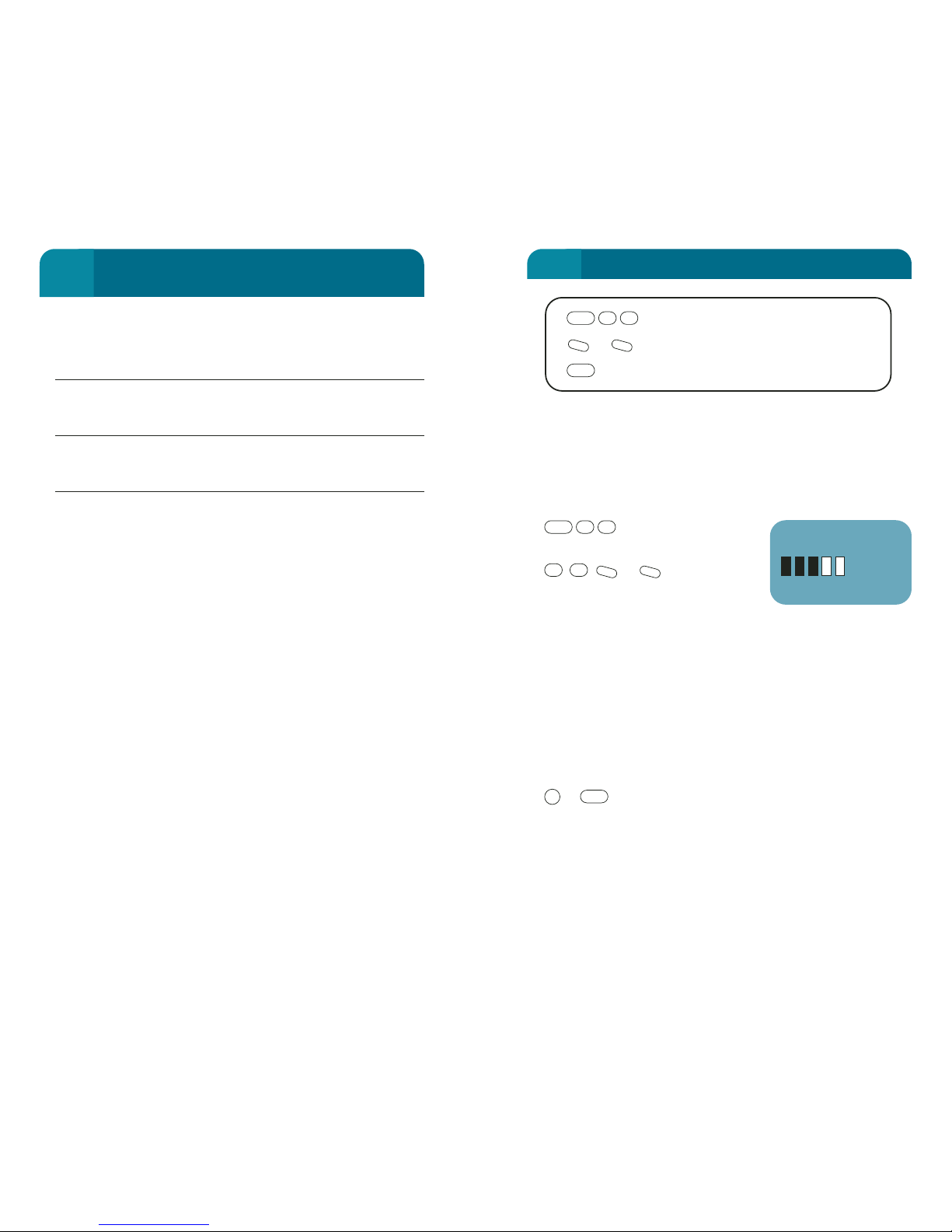
Prior Talk Request Indicates that a high priority Talk
request has been sent to gain
immediate access to Talk state
without being queued.
Detach Request Indicates that the S2 has requested to
detach from the CUG channel and
return to Standby mode.
CUG NotActive Indicates that the CUG channel has
been cleared down while the S2 was
in Listen mode.
Push to Talk (PTT) Operation
A customised PTT microphone can be connected to the
handset cradle to provide easier operation. The PTT
microphone must be supplied by Optus since it must be
modified above the standard off-the-shelf product.
The PTT mic allows the user to send Talk Requests, Listen
Requests and provides easier user operation. Priority Talk
Requests cannot be generated from the PTT mic. The handset
must be in the cradle for the PTT mic to operate correctly.
The handset must be used to attach (or detach) the
transceiver to the CUG channel – this cannot be performed
using the PTT mic.
When in Listen mode, a single press of the PTT switch will
activate a Talk Request. The user will hear the “Talk” beep
once the unit has been granted Talk permission (“Talk” is
displayed on the handset display).
The user must hold the PTT switch in for the whole time that
the user is talking. Releasing the PTT switch while in Talk
mode will activate a Listen Request, and the unit will return to
Listen mode.
If a Talk request is initiated by the PTT switch while another
user is talking, then the handset display will change to Next.
Once the current talker relinquishes the Talk permission, then
the PTT user will gain Talk permission and must hold the PTT
switch in for the duration of the talk period.
160
FCN 84 & 85: CLOSED USER GROUP
(CUG) OPERATION
6
FCN 91: ANTENNA ADJUST
6
161
Motorised Mast
The Antenna Adjust function for the Motorised Mast allows
you to manually adjust the motorised antenna in small
increments.
Motorised Mast Antenna Setting
To display the current
setting.
, , or can be used to
increment or decrement the
antenna elevation from the current
setting. The adjustment from
current reference (00) is displayed as the adjustments are
made, and also an arrow to indicate the direction of the
adjustment.
An RSSI (Received Signal Strength Indicator) is displayed to
monitor the effect of the adjustments. This value updates
every 2 seconds.
Refer to page 78 to adjust the motorised mast antenna.
EXIT
or (hold) To exit the function. The antenna will
remain at the elevation it was last set when exiting this screen.
Planar Antenna
The Antenna Adjust function for the planar antenna is not
applicable since the antenna must be manually aligned.
Marine Antenna
The Antenna Adjust function for the Marine antenna allows
movement of the antenna in both the elevation and azimuth
CLR
STO
-
+
#
*
19
FCN
Antenna Adjust
or Incremental Adjustment
(Hold) EXIT
CLR
-
+
19
FCN
FCN 91
10
REF: 00
▲
▲
Page 87
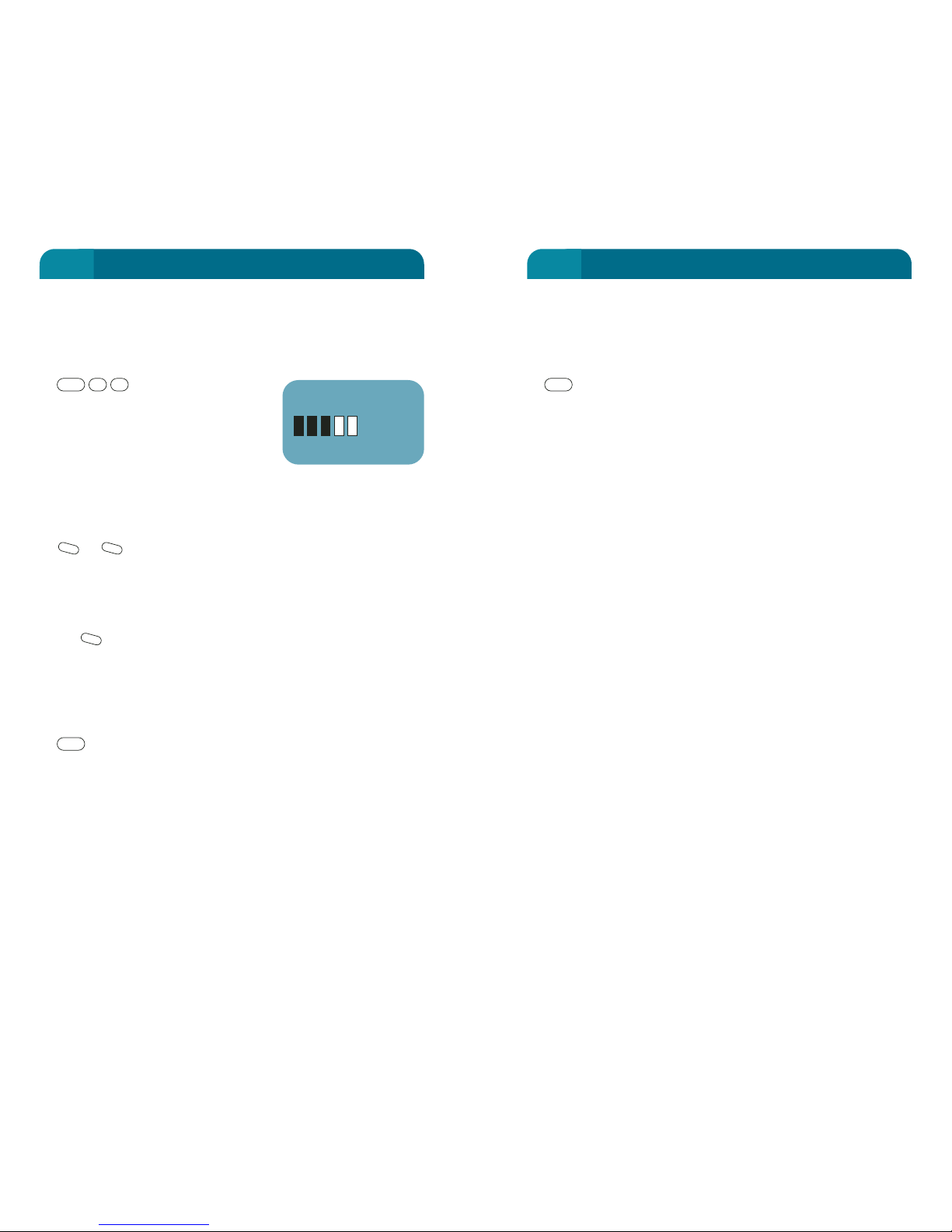
Unknown Antenna
When the transceiver does not recognise the antenna, or
there is no antenna connected the display will show
“Unknown Antenna”.
(Hold) Return to previous screen.
CLR
FCN 91: ANTENNA ADJUST
6
163
planes. In normal operation, the marine antenna will track
the satellite to its best ability and will not require manual
adjustment from the handset.
Marine Antenna Setting
To display the current
setting. This display shows the
setting of the antenna in an
abbreviated form where A=azimuth
plane and E=elevation plane. Both
readings are in degrees. The
display will also show the current plane which can be
controlled by the handset keys.
To adjust the antenna
or are used to increment or decrement the antenna
setting in the plane being displayed. The changes in the
antenna alignment are displayed as the adjustments are
made.
To switch between azimuth and elevation plane control, use
the key. The arrows for editing control will change to
indicate the plane that is currently being edited.
An RSSI is displayed to monitor the effect of the adjustments.
This value updates every 2 seconds.
EXIT
(Hold) Return to previous screen.
Dome Antenna
The Antenna Adjust function for the Dome antenna is not
applicable since the antenna is self steering.
Manual Mast Antenna
The manual mast antenna is not adjusted using the handset
so FCN 91 is not applicable for this antenna.
CLR
M
-
+
19
FCN
FCN 91: ANTENNA ADJUST
6
162
FCN 91
12 A
EOOAOOO
▲
▲
Page 88
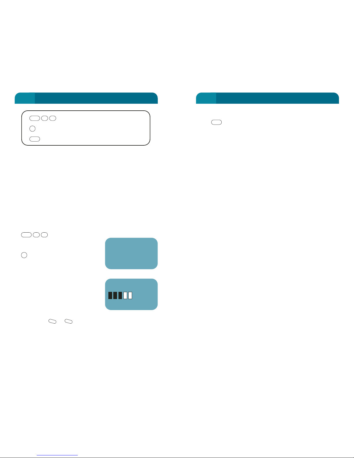
EXIT
(Hold) Return to previous screen.
Planar Antenna
The planar antenna has no steering control so does not
require calibration.
Manual Mast Antenna
The manual mast antenna does not require calibration while
in the field.
Marine Antenna
The marine antenna must be calibrated for adequate
operation of the antenna.
Read the complete instruction set before beginning
calibration of the marine antenna.
Preparation for calibration
It is vital that the antenna be installed in its permanent
position before beginning the calibration. The calibration of
the Gyro Compass inside the antenna relies on magnetic
fields to determine its relative position. Hence any distortions
in the field due to hard or soft irons in the installation must
be experienced by the antenna during its calibration process.
Calibration
To calibrate the antenna, you must turn the ship or vehicle in
two full circles over a period of at least 4 minutes on a
relatively calm or smooth surface. If aboard a boat, seek
protected waters where the wind is light. The direction of the
turn is not important and the vehicle’s track need not be a
perfect circle, but it must take at least 4 minutes to complete
– the rate of turn should not exceed 3 degrees per second.
If wind or wave action make it difficult to maintain the
required turning rate, it may be necessary to continue
through more circles. Remember to complete your circles in
no less than 4 minutes. You can’t go too slowly, but you can
go too fast!
CLR
FCN 92: ANTENNA CALIBRATE
6
165
Some of the antenna used with the Optus MobileSat S2
telephone are controlled by the handset. For this reason it is
necessary to calibrate the antenna periodically to ensure that
the transceiver provides the best steering control possible.
Motorised Mast Antenna
The Motorised Mast antenna can be calibrated to optimise the
control from the handset.
Note: Before calibrating the mast antenna, the vehicle should be stationary
and level with the antenna mounted vertically (except when using End Fire
method. Refer to page 80).
To Enter Function
To Start Calibration
This starts the automatic
calibration procedure. The antenna
calibration completes within 20
seconds.
At the completion of the
calibration the display shows the
RSSI signal, plus the last known
elevation setting of the antenna.
The FCN 92 screen returns to a
state where adjustment can be
made using or buttons (up/down arrows on screen),
showing the elevation in degrees from the horizontal.
-
+
STO
29
FCN
FCN 92: ANTENNA CALIBRATE
6
164
FCN 92
S72 MAST
Calibrate?
Antenna Calibrate
Start/Stop Automatic Tuning
(Hold) EXIT
CLR
STO
29
FCN
FCN 92
10
ELEV: 46
▲
▲
Page 89

Unknown Antenna
The antenna is not recognised by the transceiver unit. Refer to
page 168.
(Hold) Return to previous screen.
CLR
FCN 92: ANTENNA CALIBRATE
6
167
At the conclusion of the circles the handset will display a
calibration score (1-9) as an indication of how sure the
antenna is of optimal steering operation.
Calibration Score
The calibration score is a three digit number in which
• the first digit represents the quality of the calibration,
• the second digit represents an assessment of the distortion
caused by the local magnetic environment,
• the third digit is an incremental counter that keeps track of
the number of calibrations accomplished.
Scores for the calibration quality and distortion factors are 1
(worst) to 9 (best). There is a relationship between the first
and second digits: The higher the first digit’s value, the
greater the accuracy of the compass azimuth output. It is
possible to have a high calibration score in the presence of a
high distortion factor score. In general, a second digit value of
5 or lower would suggest that the antenna should be
relocated to a more benign magnetic environment.
To Enter Function
To Start Calibration
This starts the calibration procedure. The vehicle/vessel
should begin prescribing it’s circles after pressing the
button.
The display shows a countdown timer (starting at four
minutes) to indicate the time left in the current calibration.
The calibration score is also be displayed in this screen.
To STOP the Calibration
(again) Indicates to the antenna that the calibration
procedure has been completed and to assume free tracking
mode.
To Abort Calibration
Exit the FCN 92 screen at any time during the
calibration. This will stop the calibration procedure.
CLR
STO
STO
STO
29
FCN
FCN 92: ANTENNA CALIBRATE
6
166
Page 90
Motorised Mast Antenna
or toggles between ‘ON’ and ‘OFF’. When the
tracking is on, the mast will periodically step up one
adjustment and also down one ajustment to determine if the
signal is better either side of its current alignment. If this is
the case, then the antenna will maintain the optimum
alignment until the next test is performed.
KVH Marine Antenna
FCN 93 provides four tracking options for the KVH Marine
Antenna.
Manual – the user can point the antenna at the Satellite using
FCN 91. Once pointed, the KVH marine antenna will maintain
optimum RSSI using the KVH gyro compass and stabilised
platform operation.
Dither – after searching and finding the Satellite Signal, the
transceiver commands the antenna to dither in order to
maintain the optimum signal. (This is the operation used in
all previous versions of transceiver software)
GPS – The transceiver uses GPS information to calculate the
azimuth and elevation to point to the satellite. The azimuth
and elevation commands are sent to the antenna to point
directly at the satellite (NOTE: the transceiver must have a
GPS input for this mode).
GPS + Dither – Same as GPS operation, but if there is no valid
GPS position available, the antenna control will revert to
dither mode.
-
+
FCN 93: ANTENNA TYPE
6
169
This function displays the antenna type that is connected
to the Optus MobileSat S2 antenna port. This is a read-only
screen.
Only MobileSat authorised antennas are designed to operate
with the Optus MobileSat S2 unit. If the transceiver does not
recognise the antenna (display shows UNKNOWN) then the
standard transceiver will not attempt to make or receive calls.
To Display Antenna Type
Antenna description is
displayed.
Change Mode
or toggles between
settings for motorised mast or
marine antenna.
The display flashes, showing the mode has been changed but
not saved.
SAVE and EXIT
Save the setting and EXIT.
EXIT
Return to previous screen.
CLR
STO
-
+
39
FCN
FCN 93: ANTENNA TYPE
6
168
Antenna Type/Tracking
or Change Tracking Status
SAVE AND EXIT
EXIT without saving
CLR
STO
-
+
39
FCN
FCN 93
S72 MAST
TRACK: Off
Page 91
Reset
To remove the programmed key sequence from P1, just press
and hold, then press (momentarily) to erase the
hot key function (ie: enter no sequence). Resetting the
programmed key sequence is not protected by passwords.
Save the Programmed Function
Save the programmed function and EXIT. A double beep
is heard when the programming mode ends.
Note: While in program mode, the key is treated as any other key and
will not exit the program mode or Clear the last entry. The key cannot
be saved in a program. P2 cannot be recalled while in P1 programming
mode.
Run the Programmed Function
To run the P1 key sequence, start in the Standby screen and
press momentarily. If no program has been saved, an
Error Beep will sound. The programmed key sequence will be
recalled step by step, each step being displayed on the
screen.
While a P1 program is running, only the (momentarily)
key will abort the program.
Return to previous screen.
CLR
P1
P1
PWR
CLR
P1
P1P1
P1: PROGRAMMABLE FUNCTION 1
6
171
This allows you to set a commonly used key sequence as a
hot key. When P1 is selected, the key sequence is called up
immediately. P1 can be programmed or recalled in Partial or
Full Lock modes.
Note that P1 operates differently for transceivers with CUG
capability.
To Program
(Hold) When programming a
P1 function, an indicator will
appear in the Standby screen.
Any key sequence
may be entered and assigned to
the hot key .
All of the keys pressed while in programming mode will be
performed when is recalled. If an incorrect key
sequence is entered, it is recommended to reset and
start again.
When programming a lock function (FCN 6X or 7X) in the
sequence, recalling as a hot key will prompt for the
Confidential Code before stepping to the following
programmed key sequence.
A maximum of fifty keystokes can be recorded.
P1P1
P1
P1
P1
Select Sequence
P1
P1: PROGRAMMABLE FUNCTION 1
6
170
Programmable Function 1
Select Key Sequence
SAVE Sequence as P1 and EXIT
EXIT without saving
CLR
STO
Select Sequence
P1
P1 7:26pm
10
Standby
Page 92
This allows you to set a commonly used key sequence as a
‘hot’ key. When P2 is selected, the key sequence is called up
immediately. P2 can be programmed or recalled in Partial or
Full Lock modes.
Note that P2 operates differently for transceivers with CUG
capability.
To Program
(Hold) When programming a P2 function, an indicator
will appear in the Standby screen.
Any key sequence
may be entered and assigned to
the hot key
All of the keys pressed while in
programming mode will be
performed when is recalled.
If an incorrect key sequence is
entered, it is recommended to reset and start again.
When programming a lock function (FCN 6X or 7X) in the
sequence, recalling will prompt for the Confidential
Code before stepping to the following programmed key
sequence.
A maximum of fifty keystrokes can be recorded.
P2
P2
P2
P2
P2
Select Sequence
P2
172
Reset
To remove the programmed key sequence from P2, just press
and hold, then press (momentarily) to erase the
hot key function (ie: enter no sequence). Resetting the
programmed key sequence is not protected by passwords.
Save the Programmed Function
This saves the programmed function and EXIT. A double
beep is heard when the programming mode ends.
Note: While in program mode, the key is treated as any other key and
will not exit the program mode. The key cannot be saved in a program.
P1 cannot be recalled while in P2 programming mode.
Run the Programmed Function
To run the P2 key sequence, start in the Standby screen and
press momentarily. If no program has been saved, an
Error Beep will sound. The programmed key sequence will be
recalled step by step, each step being displayed on the
screen.
While a P2 program is running, only the (momentarily)
key will abort the program.
Return to previous screen.
CLR
P2
P2
PWR
CLR
P2
P2P2
173
Programmable Function 2
Select Key Sequence
SAVE Sequence as P2 and EXIT
EXIT without saving
CLR
STO
Select Sequence
P2
P2 7:27pm
10
Standby
P2: PROGRAMMABLE FUNCTION 2
6
P2: PROGRAMMABLE FUNCTION 2
6
Page 93

Application Modules
The Optus MobileSat S2 telephone is available in a range of
application modules that allow for a greater flexibility in
installation. The application modules are presented in the
following list:
Module 1 S2 transceiver unit
Module 2 Vehicle installation kit
Module 6 GPS option kit
Module 11 R41 planar antenna kit
Module 17 Antenna cable (6m)
Module 18 Antenna cable (3m)
Module 27 Manual Mast Antenna
Module 28 Dome Antenna
Module 29 Dome Magenetic Mount
It is recommended that you keep the cardboard
packaging for use in the event that you have to return
the system for repair.
174
Before You Call For Assistance
This section deals with fixing problems you may encounter.
Generally most problems can be easily solved with a little
thought. The best approach is to retry the steps you were doing
again, paying more attention to all detail. Reading this User
Manual is always a good start.
Customer support of this product is provided through an
Authorised MobileSat Dealer Network. If you call your dealer,
they will make every effort to respond quickly and resolve your
problem. However there are some things you can do before
calling your dealer. This may help you solve your problem
yourself or make it easier for the dealer to solve it for you.
Read this section carefully to see if your problem is described.
Try the suggested fixes and if all fails, call your dealer.
The phone will not turn ON
• Make sure that the vehicle’s battery is fully charged. Try
again with vehicle’s engine running.
• Check the fuse to the battery.
• Try pressing the PWR key longer (more than 1 second).
• Try powering on the unit using the ignition input.
The phone displays "No Service"
• The antenna’s view of the satellite is obstructed or is not
tuned correctly.
• Clear the view of the antenna and adjust for peak signal
strength. Refer page 77.
The phone displays "Standby" but I cannot make a call
• If you have just bought the phone make sure it has been
commissioned. Check with your dealer.
• If you see "FL" or "PL" on the display, your phone is in lock
mode. Please unlock with Confidential Code (FCN 62)
before attempting to make a call.
• Try again a minute or two later. The network may be
congested.
• Check FCN 93 responds with antenna identification.
175
OPTIONAL ACCESSORIES
6
EXPERIENCING PROBLEMS
6
OPTIONAL ACCESSORIES
7
EXPERIENCING PROBLEMS
8
Page 94

Phone turns off by itself
The phone may turn off by itself for the following reasons:
• over/under voltage.
• over/under temperature.
• ignition turned off.
• horn alert timer shutdown.
• RTS line of data cable may have deactivated.
• internal fault detected.
If the Optus MobileSat S2 fails to operate correctly, or the
handset buttons or display indicate problems, you should
power down the unit using the handset’s button (or
ignition) and then remove the POWER & HANDSET connector
from the unit. Do Not remove the POWER & HANDSET
connector from the unit while the handset display is still
active, since any recent changes will not be saved. If the
Optus MobileSat S2 does not recover consult your Dealer.
PWR
177
Major Fault Alarm and the Phone is Hot
• A major fault is indicated. When either of the CH or GEN
lights are Steady Red.
• If the phone has been exposed to direct sunlight or was not
well ventilated, place the phone in a shaded well ventilated
area, turn off and allow to cool for about 15 minutes.
Signal appears weak (RSSI < 5)
• Ensure mast antenna is vertical (vehicle should be
horizontal).
• Check for obstructions overhead, refer to page 77.
• Check that antenna is clean and free from dust, bugs, etc.
• Antenna connection is loose or dirty/wet.
• RSSI approx. 5 expected for aero antenna.
Notes on Installation
Repair, service and installation should be handled only
through an Authorised MobileSat Dealer. DO NOT attempt to
install, service, repair or disassemble your phone as it has no
user serviceable parts and the warranty on the unit will
become void.
Installed Location
The phone will not operate effectively in temperatures greater
than 60ºC so ensure that the phone is not maintained in
direct sunlight, and that ventilation is provided to keep the
phone from overheating.
176
OPTIONAL ACCESSORIES
6
EXPERIENCING PROBLEMS
6
EXPERIENCING PROBLEMS
8
EXPERIENCING PROBLEMS
8
Page 95

Fault Description
23 Antenna controller error or no response from
antenna control
24 Antenna initialisation required
25 Antenna adjustment mechanism jammed
26 Antenna operation error
27 DTI error
28 VFI error
29 HPA ON fail – Rx not ready
30 HPA ON fail – Tx not ready
31 HPA ON fail – UW Lost
32 HPA ON fail – AFC error
33 HPA ON fail – ASC failure
34 HPA ON fail – HPA failure
35 Marine Antenna K91 – Gyro compass alarm
36 Marine Antenna K91 – Gyro Inclonometer alarm
37 OS9 Error
38 Start Call Failure
39 Antenna Call Failure K91
40 Antenna Link Failure
41 HPA Reset (long)
42 HPA bad response packet
43 HPA bad Checksum
44 HPA reset
45 Link pipe error
46 External Alarm INPUT
47 SW Watchdog fail
179
Fault Messages
The following table explains some of the fault messages that
appear on the handset screen
Table 9: Fault Description
Fault Description
1 Transceiver internal temp > +70ºC
2 Transceiver internal temp < -15ºC
3 Transceiver internal temp > +65ºC
4 Transceiver internal temp < -10ºC
5 Battery Voltage > 32V
6 Battery Voltage < 10.5V
7 Alarm signal detected from HPA Assembly
8 Rx channel lock alarm
9 Tx channel lock alarm
10 Power alarm detected from HPA Assembly
11 Transmitter alarm detected from HPA Assembly
12 Base – HPA Assembly communications fault
13 Flash memory error
14 Channel correction limit exceeded
15 Rx frequency outside normal band
16 Tx frequency outside normal band
17 Warning: Battery voltage > 31.0V
18 Warning: Battery voltage < 11.5V
19 Power supply voltage > nominal +10%
20 Power supply voltage < nominal -10%
21 Transceiver received wrong system operating ID
22 GPS not connected or GPS parameter not set
178
OPTIONAL ACCESSORIES
6
EXPERIENCING PROBLEMS
6
EXPERIENCING PROBLEMS
8
EXPERIENCING PROBLEMS
8
Page 96

Fault Description
48 HPA Temperature alarm
49 Dome antenna alarm (1)
50 Dome antenna alarm (2)
51 Invalid Freq sent to Dome antenna
52 Invalid command sent to Dome antenna
53 Error response from Dome antenna
EXPERIENCING PROBLEMS
8
180
SPECIFICATIONS
9
181
Power
Input Supply 10.5-32.0 Volts (regulated)
Maximum Ripple 150mV
The following current consumption figures are for use with a
12Volt supply and Class 1 operation.
Off <10 milliamps (12V)
Standby 0.5 Amps (12V)
In Call (Rx voice) 0.7 Amps (12V)
In Call (Tx voice) 2.3 Amps (12V)
In Call (Rx fax) 3.2 Amps (12V)
In Call (Tx fax) 3.2 Amps (12V)
Frequency Range
Transmit 1646.5-1660.5 MHz
Receive 1545.0-1559.0 MHz
Channel
Voice Channel AMBE
®
Facsimile channel Group 3, 2400 bps
Data Channel 2400 bps
Bandwidth < 4 kHz
Dimensions
Transceiver Length 267mm
Width 240mm
Height 48mm
Transceiver with cradle Length 301mm
Width 241mm
Height 61mm
Handset Length 210mm
Width 54mm
Height 37mm
RF Output Power
nominally +4dBW±1dB Class 1 (antenna connector).
nominally +1dBW±1dB Class 2 (antenna connector).
nominally +7dBW±1dB Class 3 (antenna connector).
Page 97

Your Optus MobileSat S2 Mobile Satellite Telephone is designed
to give you years of trouble free service. However, should a fault
arise, please return the unit to an Authorised Optus MobileSat
Dealer.
Full details of service agents and repair costs can be obtained
from your Authorised Dealer.
Optus Networks instructs the user of the Optus MobileSat S2 to
use it in complete accordance with the Optus MobileSat S2
User's Manual. The information in this technical manual is
relevant to Version 37 software and Version 40 software for CUG
and is advisory in nature. If there is any doubt about these
instructions, please call your Authorised MobileSat Dealer.
Optus may make improvements and changes in the products
described in this manual without notice to you. Changes will be
periodically made to the information in the new editions. Efforts
have been made to ensure that the contents of this manual are
correct. Should you find an error, Optus welcomes your
comment to improve these technical communications.
Computer Software COPYRIGHTS
The Optus products described herein this manual may contain
copyrighted Optus computer programs stored in semiconductor
memories or other media. The copyright protection for these
programs is claimed by Optus Networks Pty Limited.
The AMBE
®
voice coding technology included in this product is
protected by intellectual property rights including patent rights,
copyrights and trade secrets of Digital Voice Systems, Inc. The
user of this technology is explicitly prohibited from attempting to
decompile, reverse engineer, or disassemble the object code, or
in any other way convert the object code into a human-readable
form. This technology is licensed solely for use within this
product. US Patent Nos. 5,870,405, 5,826,222, 5,754,974,
5,701,390, 5,715,365, 5,649,050, 5,630,011, 5,581,656, 5,517,511,
5,491,772, 5,247,579, 5,226,084, and 5,195,166.
Trademarks
MobileSat
®
is a registered trademark of Optus Networks Pty Ltd
ABN 65 054 365 696.
SERVICE INFORMATION
9
183
Vibration 0.04 g2/Hz NAVMAT – P9492
EMI/EMC Rating Class B, AS/NZS CISPR 22-2002
Temperature Range -10 to +50ºC
95% humidity (0-35ºC) non
condensing
75% humidity (above 35ºC)
non-condensing
Sealing Transceiver IP54
Base Assembly Separate IP54
HPA Assembly Separate IP55
Safety AS/NZS 60950-2000 &
ACA TS 22-1997
EMR Radiocommunications
(Electromagnetic Radiation – Human
Exposure) Standard 2003 (HES)
(The AMBE®voice coding technology embodied in this product is protected
by intellectual property rights including patent rights, copyrights and trade
secrets of Digital Voice Systems, Inc.)
SPECIFICATIONS
9
182
Page 98

c. You have not provided full written particulars of the
defect to the Authorised Optus MobileSat Dealer;
d. The Goods are not branded Optus;
e. The Goods have been rented to any person;
f. The defect was caused by alterations or modifications to
the Goods that were not authorised by Optus, an
accident, misuse, abuse, fault or negligence of the
customer, improper operation including connection or
accessories not approved by Optus, lack of reasonable
care, loss of parts, tampering or attempted repair or
installation or servicing by a person not authorised by
Optus, and incorrect adjustment of the Goods’ controls;
or
g. The Goods have been damaged by lightning or a mains
power surge.
Important
Please retain your sales receipt as proof of the date of purchase.
Please retain this information as your record of the Goods’
warranty terms and conditions. This warranty applies only to
Optus MobileSat Goods purchased in Australia from Optus
Networks Pty Limited’s authorised distributors.
WARRANTY FOR AUSTRALIA
9
185
For 12 months from the date of purchase, Optus Networks Pty
Limited guarantees this MobileSat product, and its accessories,
(‘Goods’) against defects in material and workmanship under
normal use and service, provided you have exercised reasonable
care in use and service of the Goods in accordance with Optus
MobileSat’s operating instructions. This warranty is subject to
you providing to the authorised service organisation proof of the
date of purchase, full written particulars of the defect and the
conditions set out below.
The benefits conferred by this warranty in respect of the Goods
are in addition to all other rights and remedies you have under
the operation of laws generally, and in particular, the Trade
Practices Act 1974 and similar State and Territory laws.
Warranty Service Conditions
1. Subject to your statutory rights referred to above, Optus
expressly limits its liability with respect to these Goods to
repairing the Goods.
2. Optus shall not be under any liability to the customer in
respect of any loss or damage, including consequential
loss or damage, howsoever caused, which may be suffered
or incurred, or which may arise directly or indirectly in
respect of the Goods.
3. In the event the Goods require service under warranty, you
are responsible for the cost of transportation to an
Authorised Optus MobileSat Dealer. The Goods are at the
owner’s risk in transit. (Please ensure that the Goods are
suitably packaged preferably in the original packaging).
4. If the Goods are found to be in sound working order by the
authorised service organisation you may be charged a
service fee.
5. The Goods will not be eligible for warranty service if:
a. You cannot provide proof of the date of purchase of the
Goods to the Authorised Optus MobileSat Dealer;
b. You have not returned the Goods to the Authorised
Optus MobileSat Dealer;
WARRANTY FOR AUSTRALIA
9
184
Page 99

The transceiver has three small Light Emitting Diodes (LED’s), to
give an indication of the phone’s operational state.
LED 1 GEN (General) Description
Off Phone is Off
Orange Phone is initialising
Orange (Flashing) Supply voltage outside
nominal range
Green Normal
Green (flashing) Temperature outside nominal
range
Red Serious Fault (Return for
Repair)
Red (Flashing) Minor Fault (Phone will still
function)
LED 2 CH (Channel) Description
Off Phone is Off or Faulty
Orange Operating on a Voice Channel
Orange (Flashing) Searching for a Control
Channel
Green Operating on a Control
Channel
Green (flashing) Searching for a Control
Channel
Red (Flashing) Minor Fault (Phone will still
function)
Red Failed to find valid Control
Channel
TRANSCEIVER TOP PANEL
9
187
Should your Optus MobileSat S2 phone fail to operate
satisfactorily, it is recommended that you report the fault to
your Authorised MobileSat Dealer.
Please provide the following details to aid fault diagnosis.
• Type of installation – vehicle, fixed site, marine, other
• Type of antenna – mast, planar, dome
• Electronic Serial Number (ESN) of the unit – FCN 22 or label
on bottom cover
• Step by step procedure of user operations to cause the fault
(Is it repeatable?)
• Handset displays or messages including
– Signal Strength (RSSI)
– Handset progress messages
– Handset fault messages
• LED display on Base Assembly top cover (or FCN 26)
• Damage to any part of the installation
Your dealer may request more information that can be accessed
from the handset, so ensure the handset is close by when
reporting the fault.
Do not attempt to dismantle the installation without dealer
instructions as this may void warranty.
REPORTING A FAULT
9
186
Page 100
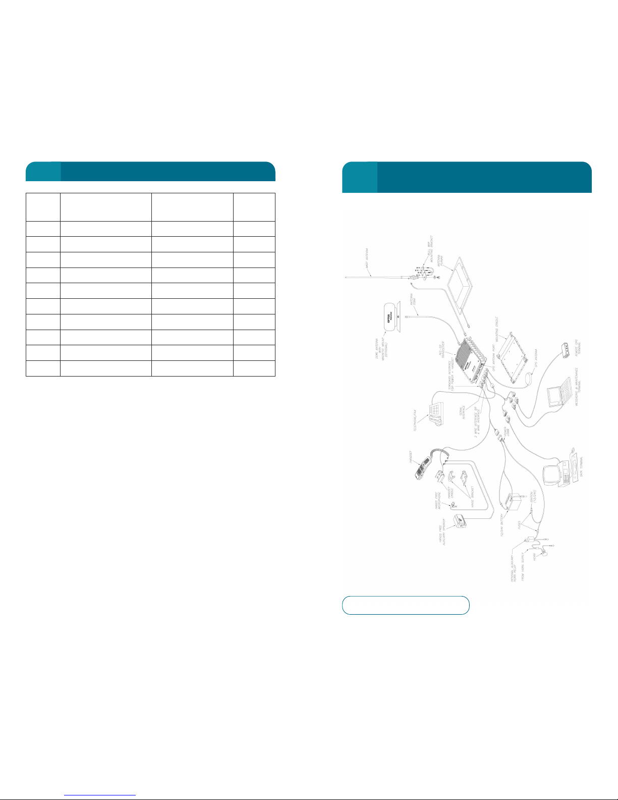
189
LED 3 SIG (Signal) Description RSSI
(Class 1)
Off No Signal 0
Red (Steady) Inadequate Signal 1
Orange (Steady) Very Poor Signal 2-3
Orange (Slow Flash) Poor Signal 4-5
Orange (Fast Flash) Fair Signal 6-7
Green (Steady) Moderate Signal 8-9
Green (Slow Flash) Good Signal 10-11
Green (Fast Flash) Very Good Signal 12-16
Red (Slow Flash) Overloading 17-19
Red (Fast Flash) Overloaded 20
TRANSCEIVER TOP PANEL
9
188
OPTUS MOBILESAT S2 COMPLETE
PRODUCT CONFIGURATION
10
Figure 10 – Complete Configuration
 Loading...