

Page 1

Operator’s Manual
optris
®
CTlaser
LT/ LTF/ 05M/ 1M/ 2M/ 3M/ 4M/ MT/ F2/ F6/ G5/ G7/ P7
Infrared thermometer
Find Quality Products Online at: [email protected]
www.GlobalTestSupply.com
Page 2

Table of contents 3-
Table of contents
Table of contents .............................................................................................................................................. 3
1 General Notes ........................................................................................................................................... 9
1.1 Intended use ....................................................................................................................................... 9
1.2 Warranty ........................................................................................................................................... 10
1.3 Scope of delivery .............................................................................................................................. 10
1.4 Maintenance ..................................................................................................................................... 11
1.5 Model Overview ................................................................................................................................ 12
2 Technical Data ........................................................................................................................................ 14
2.1 Factory settings ................................................................................................................................ 14
2.2 General specifications ...................................................................................................................... 17
2.3 Electrical specifications ..................................................................................................................... 18
Find Quality Products Online at: [email protected]
www.GlobalTestSupply.com
Page 3

-4 -
2.4 Measurement specifications [LT models] ......................................................................................... 20
2.5 Measurement specifications [05M model] ........................................................................................ 21
2.6 Measurement specifications [1M models] ........................................................................................ 22
2.7 Measurement specifications [2M models] ........................................................................................ 23
2.8 Measurement specifications [3M models] ........................................................................................ 24
2.9 Measurement specifications [4M/ MT models] ................................................................................. 25
2.10 Measurement specifications [F2/ F6/ P7 models]............................................................................. 26
2.11 Measurement specifications [G5/ G7 models] .................................................................................. 27
2.12 Optical charts .................................................................................................................................... 28
3 Mechanical Installation .......................................................................................................................... 46
3.1 Accessories....................................................................................................................................... 49
3.1.1 Air purge collar .......................................................................................................................... 49
3.1.2 Mounting bracket ...................................................................................................................... 50
Find Quality Products Online at: [email protected]
www.GlobalTestSupply.com
Page 4

Table of contents 5-
3.1.3 Water cooled housing ............................................................................................................... 51
3.1.4 Rail mount adapter for electronic box ....................................................................................... 52
3.1.5 CoolingJacket Advanced .......................................................................................................... 53
3.1.6 Outdoor protective housing ....................................................................................................... 53
3.1.7 IR app Connector ...................................................................................................................... 55
4 Electrical Installation .............................................................................................................................. 56
4.1 Connection of the cables .................................................................................................................. 56
4.1.1 Basic version............................................................................................................................. 56
4.1.2 Connector version ..................................................................................................................... 57
4.1.3 Pin assignment of connector plug (connector version only) ..................................................... 58
4.1.4 Designation [models LT/ LTF/ MT/ F2/ F6/ G5/ G7/ P7] ........................................................... 59
4.1.5 Designation [models 05M/ 1M/ 2M/ 3M] ................................................................................... 60
4.1.6 Designation [models 4M] .......................................................................................................... 61
Find Quality Products Online at: [email protected]
www.GlobalTestSupply.com
Page 5

-6 -
4.2 Power supply .................................................................................................................................... 62
4.3 Cable assembling ............................................................................................................................. 62
4.4 Ground connection ........................................................................................................................... 64
4.4.1 05M, 1M, 2M, 3M models ......................................................................................................... 64
4.4.2 4M model .................................................................................................................................. 65
4.4.3 LT, LTF, MT, F2, F6, G5, G7, P7 models ................................................................................. 66
4.5 Exchange of the sensing head ......................................................................................................... 67
4.6 Exchange of the head cable ............................................................................................................. 68
4.7 Outputs and Inputs ........................................................................................................................... 69
4.7.1 Analog outputs .......................................................................................................................... 69
4.7.2 Digital Interfaces ....................................................................................................................... 71
4.7.3 Relay outputs ............................................................................................................................ 72
4.7.4 Functional inputs (not for CTlaser 4M) ..................................................................................... 73
Find Quality Products Online at: [email protected]
www.GlobalTestSupply.com
Page 6

Table of contents 7-
4.7.5 I/O Pins (only for CTlaser 4M) .................................................................................................. 74
4.7.6 Alarms ....................................................................................................................................... 76
4.7.7 Open collector output / AL2 ...................................................................................................... 78
5 Operation ................................................................................................................................................. 79
5.1 Sensor setup ..................................................................................................................................... 79
5.2 Aiming laser ...................................................................................................................................... 91
5.3 Error messages ................................................................................................................................ 93
6 IRmobile app ........................................................................................................................................... 94
7 Software CompactConnect/ CompactPlus Connect ........................................................................... 96
7.1 Installation ......................................................................................................................................... 96
7.2 Communication settings ................................................................................................................... 98
7.2.1 Serial Interface .......................................................................................................................... 98
7.2.2 Protocol ..................................................................................................................................... 98
Find Quality Products Online at: [email protected]
www.GlobalTestSupply.com
Page 7

-8 -
7.2.3 ASCII-Protocol .......................................................................................................................... 99
7.2.4 Save parameter settings ......................................................................................................... 100
8 Basics of Infrared Thermometry ......................................................................................................... 101
9 Emissivity .............................................................................................................................................. 102
9.1 Definition ......................................................................................................................................... 102
9.2 Determination of unknown emissivity ............................................................................................. 103
9.3 Characteristic emissivity ................................................................................................................. 104
Appendix A – Table of emissivity for metals ............................................................................................. 105
Appendix B – Table of emissivity for non-metals ..................................................................................... 107
Appendix C – Smart Averaging ................................................................................................................... 108
Appendix D – Declaration of Conformity ................................................................................................... 109
Find Quality Products Online at: [email protected]
www.GlobalTestSupply.com
Page 8

General Notes 9-
1 General Notes
1.1 Intended use
Thank you for choosing the optris® CTlaser infrared thermometer.
The sensors of the optris CTlaser series are noncontact infrared temperature sensors. They calculate the
surface temperature based on the emitted infrared energy of objects [►8 Basics of Infrared
Thermometry]. An integrated double laser aiming helps to mark the measurement spot on the object
surface. This lies within the two laser points.
The CTlaser sensing head is a sensitive optical system. Please use only the thread for
mechanical installation.
• Avoid abrupt changes of the ambient temperature.
• Avoid mechanical violence on the head – this may destroy the system (expiry of warranty).
• If you have any problems or questions, please contact our service department.
Read the manual carefully before the initial start-up. The producer reserves the right to change
the herein described specifications in case of technical advance of the product.
Find Quality Products Online at: [email protected]
www.GlobalTestSupply.com
Page 9

-10 -
► All accessories can be ordered according to the referred part numbers in brackets [ ].
1.2 Warranty
Each single product passes through a quality process. Nevertheless, if failures occur contact the customer
service at once. The warranty period covers 24 months starting on the delivery date. After the warranty is
expired the manufacturer guarantees additional 6 months warranty for all repaired or substituted product
components. Warranty does not apply to damages, which result from misuse or neglect. The warranty also
expires if you open the product. The manufacturer is not liable for consequential damage or in case of a nonintended use of the product.
If a failure occurs during the warranty period the product will be replaced, calibrated or repaired without
further charges. The freight costs will be paid by the sender. The manufacturer reserves the right to
exchange components of the product instead of repairing it. If the failure results from misuse or neglect the
user has to pay for the repair. In that case you may ask for a cost estimate beforehand.
1.3 Scope of delivery
• CTlaser sensing head with connection cable and electronic box
• Mounting nut and mounting bracket (fixed)
• Operators manual
Find Quality Products Online at: [email protected]
www.GlobalTestSupply.com
Page 10

General Notes 11-
1.4 Maintenance
Blow off loose particles using clean compressed air. The lens surface can be cleaned with a soft, humid
tissue (moistened with water) or a lens cleaner (e.g. Purosol or B+W Lens Cleaner).
Never use cleaning compounds which contain solvents (neither for the lens nor for the housing).
Find Quality Products Online at: [email protected]
www.GlobalTestSupply.com
Page 11

-12 -
1.5 Model Overview
The sensors of the CTlaser series are available in the following basic versions:
Model
Model code
Measurement range
Spectral response
Typical applications
CTlaser LT
LT
-50 to 975 °C
8-14 µm
non-metallic surfaces
CTlaser F
LTF
-50 to 975 °C
8-14 µm
fast processes
CTlaser 05M
05M
1000 to 2000 °C
0.525 µm
measurement of liquid metal
CTlaser 1M
1ML
1MH
1MH1
485 to 1050 °C
650 to 1800 °C
800 to 2200 °C
1,0 µm
metals and ceramic surfaces
CTlaser 2M
2ML
2MH
2MH1
250 to 800 °C
385 to 1600 °C
490 to 2000 °C
1.6 µm
metals and ceramic surfaces
CTlaser 3M
3ML
3MH
3MH1
3MH2
3MH3
50 to 400 °C
100 to 600 °C
150 to 1000 °C
200 to 1500 °C
250 to 1800 °C
2.3 µm
metals at low object temperatures (from 50 °C)
CTlaser 4M
4ML
0 to 500 °C
2,2-6 µm
metals at low object temperatures (from 0 °C)
and very fast processes
CTlaser MT
MT
200 to 1450 °C
3.9 µm
measurement through flames
Find Quality Products Online at: [email protected]
www.GlobalTestSupply.com
Page 12

General Notes 13-
MTH
400 to 1650 °C
CTlaser F2
F2
F2H
200 to 1450 °C
400 to 1650 °C
4.24 µm
measurement of CO2-flame gases
CTlaser F6
F6
F6H
200 to 1450 °C
400 to 1650 °C
4.64 µm
measurement of CO-flame gases
CTlaser G5
G5L
G5H
G5HF
G5H1F
100 to 1200 °C
250 to 1650 °C
200 to 1450 °C
400 to 1650 °C
5,0 µm
measurement of glass
CTlaser G7
G7
100 to 1200 °C
7,9 µm
measurement of glass
CTlaser P7
P7
0 to 710 °C
7.9 µm
plastic foils and surfaces of glass
Table 1: Overview of models
In the following chapters of this manual you will find only the short model codes. On the 1M, 2M, 3M, 4M and G5
models the whole measurement range is split into several sub ranges (L, H, H1 etc.).
Find Quality Products Online at: [email protected]
www.GlobalTestSupply.com
Page 13

-14 -
2 Technical Data
2.1 Factory settings
Smart Averaging means a dynamic average adaptation at high signal edges. [Activation via
software only]. [►Appendix C – Smart Averaging]
Signal output object temperature
0 – 5 V
Emissivity
0.970 [LT/ LTF/ MT/ F2/ F6/ G5/ G7/ P7]
1.000 [05M/ 1M/ 2M/ 3M/ 4M]
Transmissivity
1.000
Average time (AVG)
0.2 s [LT]; 0.1 s [LTF/ MT/ F2/ F6/ G5/ G7/ P7]
0.001 s [05M/ 1M/ 2M/ 3M/ 4M]
Smart Averaging
Inactive (active [LTF])
Peak hold
Inactive
Valley hold
Inactive
Find Quality Products Online at: [email protected]
www.GlobalTestSupply.com
Page 14

Technical Data 15-
LT/ LTF
05M
1ML
1MH
1MH1
2ML
2MH
2MH1
3ML
3MH
3MH1
3MH2
3MH3
Lower limit temperature
range [°C]
0
1000
485
650
800
250
385
490
50
100
150
200
250
Upper limit temperature
range [°C]
500
2000
1050
1800
2200
800
1600
2000
400
600
1000
1500
1800
Lower alarm limit [°C]
(Normally closed)
30
1200
600
800
1200
350
500
800
100
250
350
550
750
Upper alarm limit [°C]
(Normally open)
100
1600
900
1400
1600
600
1200
1400
300
500
600
1000
1200
Lower limit signal output
0 V
Upper limit signal output
5 V
Temperature unit
°C
Ambient temperature compensation
(on LT, LTF, MT, F2, F6, G5, G7, P7
output at OUT-AMB as 0-5 V signal)
internal head temperature probe
Baud rate [kBaud]
115
Laser
inactive
Find Quality Products Online at: [email protected]
www.GlobalTestSupply.com
Page 15

-16 -
4ML
MT
MTH
F2
F2H
F6
F6H
G5L
G5H
G5HF
G7
P7
Lower limit temperature
range [°C]
0
200
400
200
400
200
400
100
250
200
100
0
Upper limit temperature
range [°C]
500
1450
1650
1450
1650
1450
1650
1200
400
600
1200
710
Lower alarm limit [°C]
(Normally closed)
30
400
600
400
600
400
600
200
350
350
200
30
Upper alarm limit [°C]
(Normally open)
100
1200
1400
1200
1400
1200
1400
500
900
900
500
100
Lower limit signal output
0 V
Upper limit signal output
5 V
Temperature unit
°C
Ambient temperature compensation
(on LT, LTF, MT, F2, F6, G5, G7, P7
output at OUT-AMB as 0-5 V signal)
internal head temperature probe
Baud rate [kBaud]
115 (4M: 921,6)
Laser
inactive
Find Quality Products Online at: [email protected]
www.GlobalTestSupply.com
Page 16

Technical Data 17-
2.2 General specifications
Sensing head
Electronic box
Environmental rating
IP65 (NEMA-4)
Ambient temperature 1)
-20...85 °C (4ML: -20…70 °C)
Storage temperature
-40...85 °C (3M: -40…125 °C)
-40...85 °C
Relative humidity
10...95 %, noncondensing
Material
Stainless steel
Die casting zinc
Dimensions
100 mm x 50 mm, M48x1.5
89 mm x 70 mm x 30 mm
Weight
600 g
420 g
Cable length
3 m (standard), 8 m, 15 m
Cable diameter
5 mm
Ambient temperature cable
Max. 105 °C [High temperature cable (optional):
180 °C]
Vibration
IEC 60068-2-6 (sinus shaped), IEC 60068-2-64
(broad band noise)
Find Quality Products Online at: [email protected]
www.GlobalTestSupply.com
Page 17

-18 -
Shock
IEC 60068-2-27 (25G and 50G)
Software (optional)
CompactConnect
1)
Laser will turn off automatically at ambient temperatures >50 °C. The functionality of the LCD display can be limited at ambient
temperatures below 0 °C.
2.3 Electrical specifications
Power supply
8–36 VDC (4M: 8-30 VDC / 5 V USB / max. 1,2 W)
Current draw
Max. 160 mA
Aiming laser
635 nm, 1 mW, On/ Off via programming keys or software
Outputs/ analog
(For 4M output 1 and 2 are freely selectable: Analog mA/mV, Alarm mA/mV, TCK)
Channel 1
selectable: 0/ 4–20 mA, 0–5/ 10 V, thermocouple (J or K) or alarm output (Signal source:
object temperature)
Channel 2 (LT/ LTF/ MT/ F2/ F6/ G5/ G7/ P7 only)
Head temperature [-20...180 °C] as 0–5 V or 0–10 V output or alarm output (Signal source
switchable to object temperature or electronic box temperature if used as alarm output)
Alarm output
Open collector (NPN type) output at Pin AL2 [24 V/ 50 mA]
Output impedances
mA
Max. loop resistance 500 Ω (at 8-36 VDC)
Find Quality Products Online at: [email protected]
www.GlobalTestSupply.com
Page 18

Technical Data 19-
mV
Min. 100 kΩ load impedance
Thermocouple
20 Ω
Digital interfaces
USB, RS232, RS485, Profibus DP, Modbus RTU, Ethernet (optional plug-in modules)
Relay outputs
2 x 60 VDC/ 42 VAC
RMS
, 0.4 A; optically isolated (optional plug-in module)
Functional inputs
F1-F3; software programmable for the following functions:
- external emissivity adjustment
- ambient temperature compensation
- trigger (reset of hold functions)
4M: I/O1-3 pins freely selectable via software
Find Quality Products Online at: [email protected]
www.GlobalTestSupply.com
Page 19

-20 -
2.4 Measurement specifications [LT models]
LT
LTF
Temperature range (scalable)
-50...975 °C
Spectral range
8...14 µm
Optical resolution
75:1
50:1
System accuracy
1) 2) 3)
±1 °C or ±1 %
±1,5 °C or ±1,5 %
Repeatability
1) 3)
±0.5 °C or ±0.5 %
±1 °C or ±1 %
Temperature coefficient 4)
±0,05 K/ K or ±0,05 %/ K
NETD
3) 5)
0.1 K
0.5 K
Response time (90 % signal)
120 ms
9 ms
Warm-up time
10 min
Emissivity/ Gain, Transmissivity
0.100...1.100 (adjustable via programming keys or software)
Signal processing
Average, peak hold, valley hold (adjustable via programming keys or software)
1)
at ambient temp. 23 ±5 °C; at object temperatures >0 °C (LT) / ≥ 20 °C (LTF); response time=1 s
2)
Accuracy for thermocouple output: ±2.5 °C or ±1 %, whichever is greater
3)
ε =1
4)
for ambient temperatures (head) <18 °C and >28 °C; whichever is greater
5)
at time constant of 200 ms (LT) / 100 ms (LTF) and an object temperature of 25 °C
Find Quality Products Online at: [email protected]
www.GlobalTestSupply.com
Page 20

Technical Data 21-
2.5 Measurement specifications [05M model]
05M
Temperature range (scalable)
1000…2000 °C
Spectral range
0.525 µm
Optical resolution
150:1
System accuracy
1) 2) 3)
± 1 % T
Meas
(≤ 1100 °C)
± (0.3 % T
Meas
+ 2 °C) (>1100 °C)
Repeatability
1) 3)
± 0.5 % T
Meas
(≤ 1100 °C)
± (0.1 % T
Meas
+ 1 °C) (>1100 °C)
Temperature coefficient 4)
±0,05 K/ K or ±0,05 %/ K
NETD
3) 5)
0.2 K
Response time (90 % signal) 6)
1 ms
Emissivity/ Gain
0.100...1.100 (adjustable via programming keys or software)
Transmissivity
0.100...1.000 (adjustable via programming keys or software)
Signal processing
Average, peak hold, valley hold (adjustable via programming keys or software)
1)
at ambient temp. 23 ±5 °C; whichever is greater; response time=1 s
2)
Accuracy for thermocouple output: ±2.5 °C or ±1 %, whichever is greater
3)
ε =1 4) for ambient temperatures (head) <18 °C and >28 °C; whichever is greater 5) at time constant 1 ms and object
temperature=start of measurement range + 50 °C 6) with dynamic adaptation at low signal levels
Find Quality Products Online at: [email protected]
www.GlobalTestSupply.com
Page 21

-22 -
2.6 Measurement specifications [1M models]
1ML
1MH
1MH1
Temperature range (scalable)
485...1050 °C
650...1800 °C
800...2200 °C
Spectral range
1,0 µm
Optical resolution
150:1
300:1
System accuracy
1) 2) 3)
±(0.3 % T
Meas
+2 °C)
Repeatability
1) 3)
±(0.1 % T
Meas
+1 °C)
Temperature coefficient 4)
±0,05 K/ K or ±0,05 %/ K
NETD
3) 5)
0.1 K
Response time (90 % signal) 6)
1 ms
Emissivity/ Gain
0.100...1.100 (adjustable via programming keys or software)
Transmissivity
0.100...1.000 (adjustable via programming keys or software)
Signal processing
Average, peak hold, valley hold (adjustable via programming keys or software)
1)
at ambient temp. 23 ±5 °C; whichever is greater; response time=1 s
2)
Accuracy for thermocouple output: ±2.5 °C or ±1 %, whichever is greater
3)
ε =1
4)
for ambient temperatures (head) <18 °C and >28 °C; whichever is greater
5)
at time constant 1 ms and object temperature=start of measurement range + 50 °C
6)
with dynamic adaptation at low signal levels
Find Quality Products Online at: [email protected]
www.GlobalTestSupply.com
Page 22

Technical Data 23-
2.7 Measurement specifications [2M models]
2ML
2MH
2MH1
Temperature range (scalable)
250...800 °C
385...1600 °C
490...2000 °C
Spectral range
1.6 µm
Optical resolution
150:1
300:1
System accuracy
1) 2) 3)
±(0.3 % T
Meas
+2 °C)
Repeatability
1) 3)
±(0.1 % T
Meas
+1 °C)
Temperature coefficient 4)
±0,05 K/ K or ±0,05 %/ K
NETD
3) 5)
0.1 K
Response time (90 % signal) 6)
1 ms
Emissivity/ Gain
0.100...1.100 (adjustable via programming keys or software)
Transmissivity
0.100...1.000 (adjustable via programming keys or software)
Signal processing
Average, peak hold, valley hold (adjustable via programming keys or software)
1)
at ambient temp. 23 ±5 °C; whichever is greater; response time=1 s
2)
Accuracy for thermocouple output: ±2.5 °C or ±1 %, whichever is greater
3)
ε =1
4)
for ambient temperatures (head) <18 °C and >28 °C; whichever is greater
5)
at time constant 1 ms and object temperature=start of measurement range + 50 °C
6)
with dynamic adaptation at low signal levels
Find Quality Products Online at: [email protected]
www.GlobalTestSupply.com
Page 23

-24 -
2.8 Measurement specifications [3M models]
3ML 1)
3MH 1)
3MH1 2)
3MH2 2)
3MH3 2)
Temperature range (scalable)
50...400 °C
100...600 °C
150...1000 °C
200...1500 °C
250...1800 °C
Spectral range
2,3 µm
Optical resolution
60:1
100:1
300:1
System accuracy
3) 4) 5)
±(0,3 % T
Mess
+2 °C)
Repeatability
3) 5)
±(0,1 % T
Mess
+1 °C)
Temperature coefficient 6)
±0,05 K/ K or ±0,05 %/ K
NETD
5) 7)
0,1 K
Response time (90 % signal) 8)
1 ms
Emissivity/ Gain
0,100...1,100 (adjustable via programming keys or software)
Transmissivity
0,100...1,000 (adjustable via programming keys or software)
Signal processing
Average, peak hold, valley hold (adjustable via programming keys or software)
1)
T
Object
> T
Head
+25 °C
2)
Specification valid at T
Object
≥ start of measurement range + 50 °C
3)
at ambient temp. 23 ±5 °C; whichever is greater; response time=1 s
4)
Accuracy for thermocouple output: ±2.5 °C or ±1 %, whichever is greater
5)
= 1 6) for ambient temperatures (head) <18 °C and >28 °C; whichever is greater 7) at time constant 1 ms and object
temperature=start of measurement range + 50 °C 8) with dynamic adaptation at low signal levels
Find Quality Products Online at: [email protected]
www.GlobalTestSupply.com
Page 24

Technical Data 25-
2.9 Measurement specifications [4M/ MT models]
4ML
MT
MTH
Temperature range (scalable)
0...500 °C
200...1450 °C
400...1650 °C
Spectral range
2,2-6 µm
3,9 µm
Optical resolution
33:1
45:1
System accuracy
1) 2)
±(0,3 % T
Mess
+2 °C)
±1 % 3)
Repeatability 1)
±(0,1 % T
Mess
+1 °C)
±0,5 % or 0,5 °C 3)
Temperature coefficient 4)
±0,05 K/ K or ±0,03 %/ K 5)
±0,05 K/ K or ±0,05 %/ K
NETD 6)
180 mK
0,1 K
Response time (90 % signal)
300 µs (Exposure time: 90 µs)
10 ms
Emissivity/ Gain
0,100...1,100 (adjustable via programming keys or software)
Transmissivity
0,100...1,000 (adjustable via programming keys or software)
Signal processing
Average, peak hold, valley hold (adjustable via programming keys or software)
1)
at ambient temp. 23 ±5 °C; whichever is greater; response time=1 s
2)
Accuracy for thermocouple output: ±2.5 °C or ±1 %
3)
MT: at object temperatures >300 °C with dynamic adaptation at low signal levels
4)
for ambient temperatures (head) <18 °C and >28 °C; whichever is greater
5)
for ambient temperatures > 10 °C; whichever is greater
6)
= 1 7) at time constant 1 ms and TObj = 50 °C
Find Quality Products Online at: [email protected]
www.GlobalTestSupply.com
Page 25

-26 -
2.10 Measurement specifications [F2/ F6/ P7 models]
F2
F2H
F6
F6H
P7
Temperature range (scalable)
200...1450 °C
400...1650 °C
200...1450 °C
400...1650 °C
0…710 °C
Spectral range
4,24 µm
4,64 µm
7,9 µm
Optical resolution
45:1
System accuracy
1), 2)
±1 % 3)
±1,5 °C or ±1 %
Repeatability 1)
±0,5 °C or ±0,5 % 2)
Temperature coefficient 4)
±0,05 K/ K or ±0,05 %/ K
NETD 5)
0,1 K
0,5 K
Response time (90 % signal)
10 ms
150 ms
Emissivity/ Gain
0.100...1.100 (adjustable via programming keys or software)
Transmissivity
0.100...1.000 (adjustable via programming keys or software)
Signal processing
Average, peak hold, valley hold (adjustable via programming keys or software)
1)
at ambient temp. 23 ±5 °C; whichever is greater; response time=1 s
2)
Accuracy for thermocouple output: ±2.5 °C or ±1 %
3)
at object temperatures >300 °C (F2/F6)
4)
for ambient temperatures (head) <18 °C and >28 °C; whichever is greater
5)
= 1; at time constant 200 ms and object temperature=start of measurement range + 50 °C
Find Quality Products Online at: [email protected]
www.GlobalTestSupply.com
Page 26

Technical Data 27-
2.11 Measurement specifications [G5/ G7 models]
G5L
G5H
G5HF
G5H1F
G7
Temperature range (scalable)
100...1200 °C
250...1650 °C
200...1450 °C
400...1650 °C
100…1200 °C
Optical resolution
5,0 µm
7,9 µm
System accuracy
1) 2), 3)
45:1
70:1
45:1
Repeatability
1) 3)
±1,5 °C or ±1 %
Temperature coefficient 4)
±0,05 K/ K or ±0,05 %/ K
NETD
3) 5)
±0,5 °C or ±0,5 %
Response time (90 % signal)
0,1 K
0,5 K
Emissivity/ Gain
120 ms
80 ms
10 ms
150 ms
Transmissivity
0,100...1,100 (adjustable via programming keys or software)
Signal processing
0,100...1,100 (adjustable via programming keys or software)
Optical resolution
Mittelwert, MAX, MIN (adjustable via programming keys or software)
1)
at ambient temp. 23 ±5 °C; whichever is greater; response time=1 s
2)
Accuracy for thermocouple output: ±2.5 °C or ±1 %
3)
= 1
4)
for ambient temperatures (head) <18 °C and >28 °C; whichever is greater
5)
at time constant 200 ms and object temperature=start of measurement range + 50 °C
Find Quality Products Online at: [email protected]
www.GlobalTestSupply.com
Page 27

-28 -
2.12 Optical charts
The following optical charts show the diameter of the measuring spot in dependence on the distance
between measuring object and sensing head. The spot size refers to 90 % of the radiation energy.
The distance is always measured from the front edge of the sensing head.
As an alternative to the optical diagrams, the spot size calculator can also be used on the
Optris website or via the Optris calculator app. The app can be downloaded for free from
the Google Play store (see QR code).
D = Distance from front of the
sensing head to the object
S = Spot size
The size of the measuring object and the optical resolution of the infrared thermometer
determine the maximum distance between sensing head and measuring object.
In order to prevent measuring errors the object should fill out the field of view of the optics
completely.
Consequently, the spot should at all times have at least the same size like the object or should
be smaller than that.
Find Quality Products Online at: [email protected]
www.GlobalTestSupply.com
Page 28

Technical Data 29-
LT
Optics: CF1
D:S (focus distance) = 75:1/ 0.9mm@70mm
D:S (far field) = 3.5:1
LT
Optics: SF
D:S (focus distance) = 75:1/ 16mm@1200mm
D:S (far field) = 24:1
Find Quality Products Online at: [email protected]
www.GlobalTestSupply.com
Page 29

-30 -
LT
Optics: CF2
D:S (focus distance) = 75:1/ 1.9mm@150mm
D:S (far field) = 7:1
LT
Optics: CF3
D:S (focus distance) = 75:1/ 2.75mm@200mm
D:S (far field) = 9:1
Find Quality Products Online at: [email protected]
www.GlobalTestSupply.com
Page 30

Technical Data 31-
LT
Optics: CF4
D:S (focus distance) = 75:1/ 5.9mm@450mm
D:S (far field) = 18:1
LTF
Optics: SF
D:S (focus distance) = 50:1/ 24mm@1200mm
D:S (far field) = 20:1
Find Quality Products Online at: [email protected]
www.GlobalTestSupply.com
Page 31

-32 -
LTF
Optics: CF1
D:S (focus distance) = 50:1/ 1.4mm@70mm
D:S (far field) = 3.5:1
LTF
Optics: CF2
D:S (focus distance) = 50:1/ 3mm@150mm
D:S (far field) = 6:1
Find Quality Products Online at: [email protected]
www.GlobalTestSupply.com
Page 32

Technical Data 33-
LTF
Optics: CF3
D:S (focus distance) = 50:1/ 4mm@200mm
D:S (far field) = 8:1
LTF
Optics: CF4
D:S (focus distance) = 50:1/ 9mm@450mm
D:S (far field) = 16:1
Find Quality Products Online at: [email protected]
www.GlobalTestSupply.com
Page 33

-34 -
1MH/ 1MH1/ 2MH/ 2MH1/ 3MH1-H3
Optics: FF
D:S (focus distance) = 300:1/ 12mm@ 3600mm
D:S (far field) = 115:1
05M/ 1ML/ 2ML Optics: FF
D:S (focus distance) = 150:1/ 24mm@ 3600mm
D:S (far field) = 84:1
1MH/ 1MH1/ 2MH/ 2MH1/ 3MH1-H3
Optics: SF
D:S (focus distance) = 300:1/ 3,7mm@ 1100mm
D:S (far field) = 48:1
05M/ 1ML/ 2ML Optics: SF
D:S (focus distance) = 150:1/ 7,3mm@ 1100mm
D:S (far field) = 42:1
Find Quality Products Online at: [email protected]
www.GlobalTestSupply.com
Page 34

Technical Data 35-
1MH/ 1MH1/ 2MH/ 2MH1/ 3MH1-H3
Optics: CF2
D:S (focus distance) = 300:1/ 0,5mm@ 150mm
D:S (far field) = 7,5:1
1ML/ 2ML Optics: CF2
D:S (focus distance) = 150:1/ 1mm@ 150mm
D:S (far field) = 7:1
1MH/ 1MH1/ 2MH/ 2MH1/ 3MH1-H3
Optics: CF3
D:S (focus distance) = 300:1/ 0,7mm@ 200mm
D:S (far field) = 10:1
1ML/ 2ML Optics: CF3
D:S (focus distance) = 150:1/ 1,3mm@ 200mm
D:S (far field) = 10:1
Find Quality Products Online at: [email protected]
www.GlobalTestSupply.com
Page 35

-36 -
3MH Optics: FF
D:S (focus distance) = 100:1/ 36mm@ 3600mm
D:S (far field) = 65:1
1MH/ 1MH1/ 2MH/ 2MH1/ 3MH1-H3
Optics: CF4
D:S (focus distance) = 300:1/ 1,5mm@ 450mm
D:S (far field) = 22:1
1ML/ 2ML Optics: CF4
D:S (focus distance) = 150:1/ 3mm@ 450mm
D:S (far field) = 20:1
Find Quality Products Online at: [email protected]
www.GlobalTestSupply.com
Page 36

Technical Data 37-
3ML Optics: FF
D:S (focus distance) = 60:1/ 60mm@ 3600mm
D:S (far field) = 45:1
3MH Optics: SF
D:S (focus distance) = 100:1/ 11mm@ 1100mm
D:S (far field) = 38:1
3ML Optics: SF
D:S (focus distance) = 60:1/ 18.3mm@ 1100mm
D:S (far field) = 30:1
Find Quality Products Online at: [email protected]
www.GlobalTestSupply.com
Page 37

-38 -
3MH Optics: CF1
D:S (focus distance) = 100:1/ 0.85mm@ 85mm
D:S (far field) = 4:1
3ML Optics: CF1
D:S (focus distance) = 60:1/ 1.4mm@ 85mm
D:S (far field) = 4:1
3MH Optics: CF2
D:S (focus distance) = 100:1/ 1.5mm@ 150mm
D:S (far field) = 7:1
3ML Optics: CF2
D:S (focus distance) = 60:1/ 2.5mm@ 150mm
D:S (far field) = 6:1
Find Quality Products Online at: [email protected]
www.GlobalTestSupply.com
Page 38

Technical Data 39-
3MH Optics: CF3
D:S (focus distance) = 100:1/ 2mm@ 200mm
D:S (far field) = 9:1
3ML Optics: CF3
D:S (focus distance) = 60:1/ 3.4mm@ 200mm
D:S (far field) = 8:1
3MH Optics: CF4
D:S (focus distance) = 100:1/ 4.5mm@ 450mm
D:S (far field) = 19:1
3ML Optics: CF4
D:S (focus distance) = 60:1/ 7.5mm@ 450mm
D:S (far field) = 17:1
Find Quality Products Online at: [email protected]
www.GlobalTestSupply.com
Page 39

-40 -
MT/ MTH/ F2/ F2H/ F6/ F6H/ G5L/ G5HF/
G5H1F/ G7/ P7 Optics: CF1
D:S (focus distance) = 45:1/ 1.6mm@70mm
D:S (far field) = 3:1
G5H Optics: CF1
D:S (focus distance) = 70:1/ 1mm@70mm
D:S (far field) = 3.4:1
MT/ MTH/ F2/ F2H/ F6/ F6H/ G5L/ G5HF/
G5H1F/ G7/ P7 Optics: SF
D:S (focus distance) = 45:1/ 27mm@1200mm
D:S (far field) = 25:1
G5H Optics: SF
D:S (focus distance) = 70:1/ 17mm@1200mm
D:S (far field) = 33:1
Find Quality Products Online at: [email protected]
www.GlobalTestSupply.com
Page 40

Technical Data 41-
MT/ MTH/ F2/ F2H/ F6/ F6H/ G5L/ G5HF/
G5H1F/ G7/ P7 Optics: CF2
D:S (focus distance) = 45:1/ 3.4mm@150mm
D:S (far field) = 6:1
G5H Optics: CF2
D:S (focus distance) = 70:1/ 2.2mm@150mm
D:S (far field) = 6.8:1
MT/ MTH/ F2/ F2H/ F6/ F6H/ G5L/ G5HF/
G5H1F/ G7/ P7 Optics: CF3
D:S (focus distance) = 45:1/ 4.5mm@200mm
D:S (far field) = 8:1
G5H Optics: CF3
D:S (focus distance) = 70:1/ 2.9mm@200mm
Find Quality Products Online at: [email protected]
www.GlobalTestSupply.com
Page 41

-42 -
MT/ MTH/ F2/ F2H/ F6/ F6H/ G5L/ G5HF/
G5H1F/ G7/ P7 Optics: CF4
D:S (focus distance) = 45:1/ 10mm@450mm
D:S (far field) = 15:1
G5H Optics: CF4
D:S (focus distance) = 70:1/ 6.5mm@450mm
4ML Optics: FF
D:S (focus distance) = 30:1/ 120mm@3600mm
D:S (far field) = 25:1
Find Quality Products Online at: [email protected]
www.GlobalTestSupply.com
Page 42

Technical Data 43-
4ML Optics: CF1
D:S (focus distance) = 30:1/ 2,4mm@70mm
D:S (far field) = 3:1
4ML Optics: SF
D:S (focus distance) = 30:1/ 36,7mm@1100mm
D:S (far field) = 20:1
Find Quality Products Online at: [email protected]
www.GlobalTestSupply.com
Page 43

-44 -
4ML Optics: CF3
D:S (focus distance) = 30:1/ 6,7mm@200mm
D:S (far field) = 8:1
4ML Optics: CF2
D:S (focus distance) = 30:1/ 5mm@150mm
D:S (far field) = 6:1
Find Quality Products Online at: [email protected]
www.GlobalTestSupply.com
Page 44

Technical Data 45-
4ML Optics: CF4
D:S (focus distance) = 30:1/ 15mm@450mm
D:S (far field) = 15:1
Find Quality Products Online at: [email protected]
www.GlobalTestSupply.com
Page 45

-46 -
3 Mechanical Installation
• Keep the optical path free of any obstacles.
• For an exact alignment of the head to the object activate the integrated double laser.
[►5.2 Aiming laser]
The CTlaser is equipped with a metric M48x1.5 thread and can be installed either directly via the sensor
thread or with help of the supplied mounting nut (standard) and fixed mounting bracket (standard) to a
mounting device available.
Figure 1: CTlaser sensing head
Find Quality Products Online at: [email protected]
www.GlobalTestSupply.com
Page 46

Mechanical Installation 47-
Figure 2: Mounting bracket, adjustable in one axis [Order No. - ACCTLFB] – standard scope of supply
Find Quality Products Online at: [email protected]
www.GlobalTestSupply.com
Page 47

-48 -
Figure 3: Electronic box
Find Quality Products Online at: [email protected]
www.GlobalTestSupply.com
Page 48

Mechanical Installation 49-
3.1 Accessories
3.1.1 Air purge collar
• Use oil-free, technically clean air only.
• The needed amount of air (approx. 40...120 l/ min.) and pressure (approx. 1,1...8 bar)
depends on the application and the installation conditions on-site.
The lens must be kept clean at all times from dust, smoke, fumes and other contaminants in order to avoid
reading errors. These effects can be reduced by using an air purge collar.
Figure 4: Air purge collar [Order No.: ACCTLAP], hose connection: 6x8 mm, thread (fitting): G 1/8 inch
Find Quality Products Online at: [email protected]
www.GlobalTestSupply.com
Page 49

-50 -
3.1.2 Mounting bracket
This adjustable mounting bracket allows an adjustment of the sensor head in two axes.
Figure 5: Mounting bracket, adjustable in two axes [Order No.: ACCTLAB]
Find Quality Products Online at: [email protected]
www.GlobalTestSupply.com
Page 50

Mechanical Installation 51-
3.1.3 Water cooled housing
To avoid condensation on the optics an air purge collar is recommended.
The sensing head is for application at ambient temperatures up to 85 °C. For applications at higher ambient
temperatures we recommend the usage of the optional water cooled housing (operating temperature up to
175 °C) and the optional high temperature cable (operating temperature up to 180 °C).
Figure 6: Water cooled housing [Order No.: ACCTLW], hose connection: 6x8 mm, thread (fitting): G 1/8 inch
Water flow rate: approx. 3…5 l/ min
Water pressure: approx. 3…10 bar
(Cooling water temperature should not exceed 30 °C)
Find Quality Products Online at: [email protected]
www.GlobalTestSupply.com
Page 51

-52 -
3.1.4 Rail mount adapter for electronic box
With the rail mount adapter the CTlaser electronics can be mounted easily on a DIN rail (TS35) according
EN50022.
Figure 7: Rail mount adapter [Order No.: ACCTRAIL]
Find Quality Products Online at: [email protected]
www.GlobalTestSupply.com
Page 52

Mechanical Installation 53-
3.1.5 CoolingJacket Advanced
For very high ambient temperatures (up to
315 °C) the CoolingJacket Advanced (cooling
housing) is provided.
Order No.: ACCXLCJA
For detailed information see installation manual.
3.1.6 Outdoor protective housing
The CTlaser LT models and the USB server can also be used for outdoor applications by using the outdoor
protective housing (Order No.: ACCTLOPH24ZNS).
Find Quality Products Online at: [email protected]
www.GlobalTestSupply.com
Page 53

-54 -
Figure 8: Outdoor protective housing for CTlaser LT with
integrated heater, incl. prot. window (ZnS) and air purge
collar/ 24 V DC
Figure 9: Outdoor protective housing with wall mount
For detailed information see installation manual.
Find Quality Products Online at: [email protected]
www.GlobalTestSupply.com
Page 54

Mechanical Installation 55-
3.1.7 IR app Connector
The IR App Connector is used to connect the sensor to a smartphone or tablet (► 6 IRmobile app). The
Figure 10: IR app Connector: USB programming adaptor [Order No.: ACCTIAC (for CTlaser 4M: ACCTMIAC)]
connector cable can be also used for the connection to your PC in combination with the software
CompactConnect which can be downloaded for free under
Find Quality Products Online at: [email protected]
www.GlobalTestSupply.com
Page 55

-56 -
4 Electrical Installation
4.1 Connection of the cables
• For the Cooling jacket the connector version is needed.
• Connector Kit: Subsequent conversion of a standard CTlaser sensor into the connector
version (Order No.: ACCTLCONK).
4.1.1 Basic version
The basic version is supplied with a connection cable (connection
sensing head-electronics). For the electrical installation of the CTlaser
open at first the cover of the electronic box (4 screws). Below the
display are the screw terminals for the cable connection.
Figure 11: Basic version
Find Quality Products Online at: [email protected]
www.GlobalTestSupply.com
Page 56

Electrical Installation 57-
4.1.2 Connector version
Use the original ready-made, fitting connection cables which are optionally available.
Consider the pin assignment of the connector (see Figure 13).
This version has a connector plug integrated in the sensor backplane
Figure 12: Connector version
Find Quality Products Online at: [email protected]
www.GlobalTestSupply.com
Page 57

-58 -
4.1.3 Pin assignment of connector plug (connector version only)
PIN
Designation
Wire color (original sensor cable)
Figure 13: Connector plug
(exterior view)
1
Detector signal (+)
Yellow
2
Temperature probe head
Brown
3
Temperature probe head
White 4 Detector signal (–)
Green
5
Ground Laser (–)
Grey 6 Power supply Laser (+)
Pink
7
--
Not used
Find Quality Products Online at: [email protected]
www.GlobalTestSupply.com
Page 58

Electrical Installation 59-
4.1.4 Designation [models LT/ LTF/ MT/ F2/ F6/ G5/ G7/ P7]
+8...36 VDC
Power supply
Figure 14: Opened electronic box
(LT/ LTF/ MT/ F2/ F6/ G5/ G7/ P7) with terminal
connections
GND
Ground (0 V) of power supply
GND
Ground (0 V) of internal in- and outputs
OUT-AMB
Analog output head temperature (mV)
OUT-TC
Analog output thermocouple (J or K)
OUT-mV/mA
Analog output object temperature (mV or mA)
F1-F3
Functional inputs
AL2
Alarm 2 (Open collector output)
3V SW
PINK/ Power supply Laser (+)
GND
GREY/ Ground Laser (–)
BROWN
Temperature probe head
WHITE
Temperature probe head
GREEN
Detector signal (–)
YELLOW
Detector signal (+)
Find Quality Products Online at: [email protected]
www.GlobalTestSupply.com
Page 59

-60 -
4.1.5 Designation [models 05M/ 1M/ 2M/ 3M]
+8…36 VDC
Power supply
Figure 15: Opened electronic box (05M/ 1M/ 2M/ 3M) with
terminal connections
GND
Ground (0 V) of power supply
GND
Ground (0 V) of internal in- and outputs
AL2
Alarm 2 (Open collector output)
OUT-TC
Analog output thermocouple (J or K)
OUT-mV/mA
Analog output object temperature (mV or mA)
F1-F3
Functional inputs
GND
Ground (0 V)
3V SW
PINK/ Power supply Laser (+)
GND
GREY/ Ground Laser (–)
BROWN
Temperature probe head
WHITE
Temperature probe head
GREEN
Detector signal (–)
YELLOW
Detector signal (+)
Find Quality Products Online at: [email protected]
www.GlobalTestSupply.com
Page 60

Electrical Installation 61-
4.1.6 Designation [models 4M]
+8…30 VDC
Power supply
Figure 16: Opened electronic box (4M) with terminal
connections
GND
Ground (0 V) of power supply
GND
Ground (0 V) of internal in- and outputs
AL2
Alarm 2 (Open collector output)
OUT-1
Analog output mA, mV, TCK
OUT-2
Analog output mA, mV, TCK
I/O1-I/O3
In- and outputs
GND
Ground (0 V)
Pink
3 VDC, switchable, for laser-sightingtool
Gray
Ground of PIN pink
BROWN
Temperature probe head (NTC)
WHITE
Head ground
GREEN
Head power
YELLOW
Detector signal
Find Quality Products Online at: [email protected]
www.GlobalTestSupply.com
Page 61

-62 -
4.2 Power supply
Do never connect a supply voltage to the analog outputs as this will destroy the output!
The CTlaser is not a 2-wire sensor!
Use a separate, stabilized power supply unit with an output voltage in the range of 8–36 VDC
(CTlaser 4M: 8–30 VDC) which can supply 160 mA. The residual ripple should be max 200 mV.
4.3 Cable assembling
For all power and data lines use shielded cables only. The sensor shield has to be grounded.
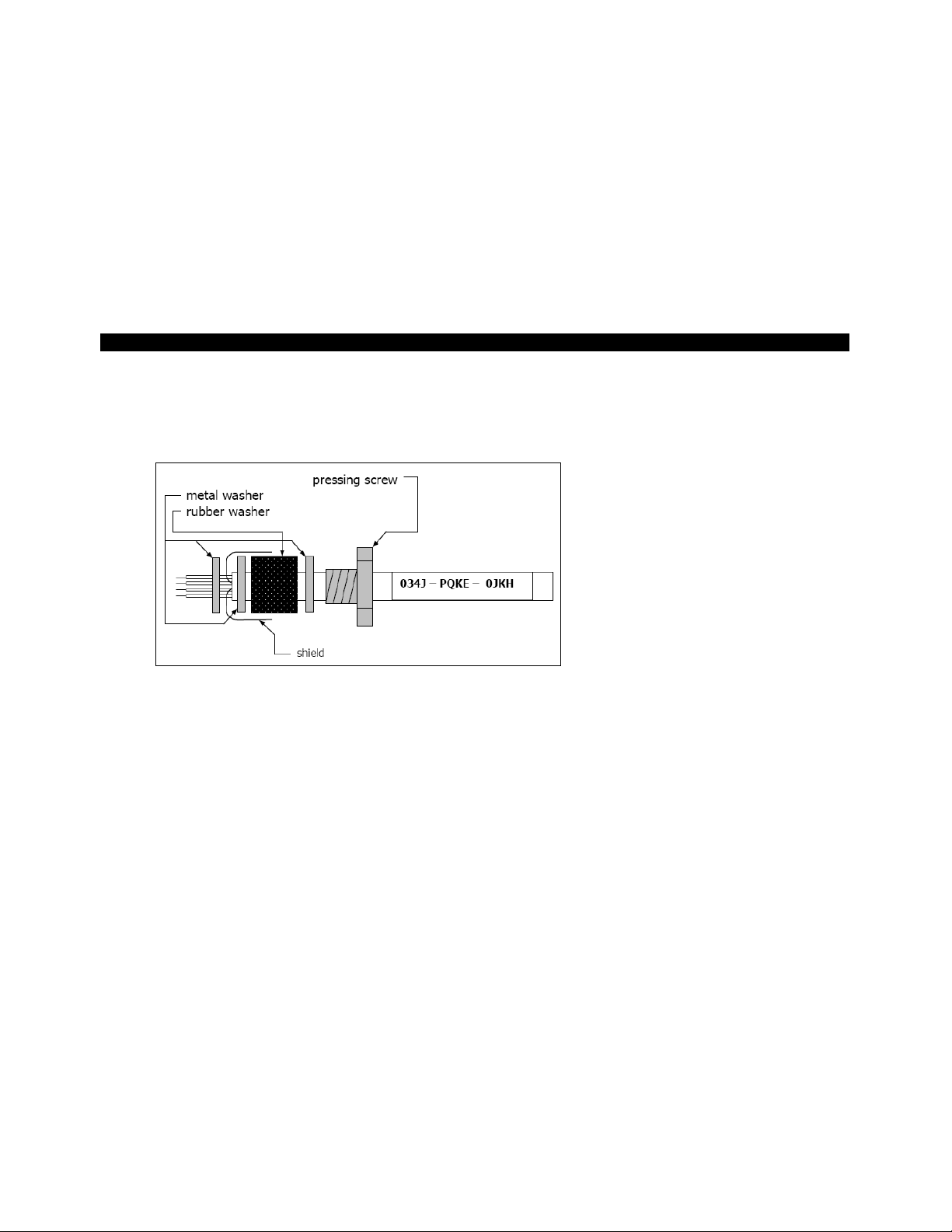
The cable gland M12x1.5 allows the use of cables with a diameter of 3 to 5 mm.
1. Remove the isolation from the cable (40 mm power supply, 50 mm signal outputs, 60 mm functional
inputs), cut the shield down to approximately 5 mm and spread the strands out.
2. Extract about 4 mm of the wire isolation and tin the wire ends. Place the pressing screw, the rubber
washer and the metal washers of the cable gland one after the other onto the prepared cable end
(see Figure 17).
Find Quality Products Online at: [email protected]
www.GlobalTestSupply.com
Page 62
Electrical Installation 63-
3. Spread the strands and fix the shield between two of the metal washers.
4. Insert the cable into the cable gland until the limit stop and screw the cap tight. Every single wire may
be connected to the according screw clamps according to their colors.
Figure 17: Cable assembling
Find Quality Products Online at: [email protected]
www.GlobalTestSupply.com
Page 63

-64 -
4.4 Ground connection
4.4.1 05M, 1M, 2M, 3M models
At the bottom side of the mainboard PCB you will find a connector
(jumper) which has been placed from factory side as shown in the
picture [bottom and middle pin connected]. In this position the
ground connections (GND power supply/ outputs) are connected with
the ground of the electronics housing.
To avoid ground loops and related signal interferences in industrial
environments it might be necessary to interrupt this connection. To
do this put the jumper in the opposite position [middle and top pin
connected].
If the thermocouple output is used the connection GND – housing
should be interrupted generally.
Figure 18: Ground connection
Find Quality Products Online at: [email protected]
www.GlobalTestSupply.com
Page 64

Electrical Installation 65-
4.4.2 4M model
On the left side of the mainboard PCB you will find a black switch which is
connecting factory-default the ground connections (GND power supply/ outputs)
with the ground of the electronics housing.
To avoid ground loops and related signal interferences in industrial
environments it might be necessary to interrupt this connection. For this
purpose, the switch must be changed.
Figure 19: Ground
connection
Find Quality Products Online at: [email protected]
www.GlobalTestSupply.com
Page 65

-66 -
4.4.3 LT, LTF, MT, F2, F6, G5, G7, P7 models
At the bottom side of the mainboard PCB you will find a
connector (jumper) which has been placed from factory
side as shown in the picture [left and middle pin
connected]. In this position the ground connections
(GND power supply/ outputs) are connected with the
ground of the electronics housing.
To avoid ground loops and related signal interferences
in industrial environments it might be necessary to
interrupt this connection. To do this put the jumper in the
other position [middle and right pin connected].
If the thermocouple output is used the connection GND
– housing should be interrupted generally.
Figure 20: Ground connection
Find Quality Products Online at: [email protected]
www.GlobalTestSupply.com
Page 66

Electrical Installation 67-
4.5 Exchange of the sensing head
• After exchanging a head the calibration code of the new head must be entered into the
electronics.
• After modification of the code a reset is necessary to activate the changes.
[►5 Operation]
• The calibration code is fixed on a label on the head. Do not remove this label or note the
code. The code is needed if the electronic must be exchanged.
• The sensing head of the CTlaser 4M cannot be exchanged.
The sensing head is already connected to the electronics by factory default. Inside a certain model group an
exchange of sensing heads and electronics is possible.
Entering of the calibration code
Every head has a specific calibration code, which is printed on the head. For a correct temperature
measurement and functionality of the sensor this calibration code must be stored into the electronic box. The
calibration code consists of five blocks with 4 characters each.
Example: EKJ0 – 0OUD – 0A1B – A17U – 93OZ
block 1 block 2 block 3 block 4 block 5
Find Quality Products Online at: [email protected]
www.GlobalTestSupply.com
Page 67

-68 To enter the code press the Up and Down key (keep pressed) and then the Mode key. The display shows
HCODE and then the 4 signs of the first block. With Up and Down each sign can be changed. Mode switches
to the next sign or next block.
Figure 21: Sensing head
4.6 Exchange of the head cable
To avoid influences on the accuracy use an exchange cable with the same wire profiles and
specification like the original one.
The sensing head cable can also be exchanged if necessary.
Find Quality Products Online at: [email protected]
www.GlobalTestSupply.com
Page 68

Electrical Installation 69-
1. For a dismantling on the head side open the cover plate on the back side of the head first. Then
remove the terminal block and loose the connections.
2. After the new cable has been installed proceed in reversed order. Be careful the cable shield is
properly connected to the head housing.
4.7 Outputs and Inputs
4.7.1 Analog outputs
The CTlaser has two analog output channels. With the CTlaser 4M the outputs are freely selectable.
Consider that there are different connection pins on the mainboard (OUT-mV/mA or OUT-TC)
according to the chosen output signal.
Output channel 1
This output is used for the object temperature. The selection of the output signal can be done via the
programming keys [►5 Operation]. The CompactConnect software allows the programming of output
channel 1 as an alarm output.
Find Quality Products Online at: [email protected]
www.GlobalTestSupply.com
Page 69

-70 -
Output signal
Range
Connection pin on CTlaser board
Voltage
0 ... 5 V
OUT-mV/mA
Voltage
0 ... 10 V
OUT-mV/mA
Current
0 ... 20 mA
OUT-mV/mA
Current
4 ... 20 mA
OUT-mV/mA
Thermocouple
TC J
OUT-TC
Thermocouple
TC K
OUT-TC
Output channel 2 [on LT/ G5/ G7/ P7 only]
The connection pin OUT AMB is used for output of the head temperature [-20–180 °C as 0–5 V or 0–10 V
signal]. The CompactConnect software allows the programming of output channel 2 as an alarm output.
Instead of the head temperature THead also the object temperature TObj or electronic box temperature TBox can
be selected as alarm source.
Find Quality Products Online at: [email protected]
www.GlobalTestSupply.com
Page 70

Electrical Installation 71-
4.7.2 Digital Interfaces
The Ethernet interface requires a minimum 12 V supply voltage. Pay attention to the notes on
the according interface manuals.
CTlaser sensors can be optionally equipped with an USB-, RS232-, RS485-, Profibus DP-*, Modbus RTU-*
or Ethernet-interface.
1. To install an interface, plug the interface board into the
place provided, which is located beside the display. In the
correct position the holes of the interface match with the
thread holes of the electronic box.
2. Press the board down to connect it and use both M3x5
screws for fixing. Plug the preassembled interface cable
with the terminal block into the male connector of the
interface board.
Figure 22: Digital interfaces
* Not for CTlaser 4M available
Find Quality Products Online at: [email protected]
www.GlobalTestSupply.com
Page 71

-72 -
4.7.3 Relay outputs
• The switching thresholds are in accordance with the values for alarm 1 and 2 [►4.7.6
Alarms]. The alarm values are set according to the ►2.1 Factory settings. For advanced
settings (change of low- and high alarm) a digital interface (USB, RS232) and the software is
needed.
• A simultaneous installation of a digital interface and the relay outputs is not possible.
The CTlaser can optionally be equipped with a relay output. The relay board will be installed in the same way
as the digital interfaces.
The relay board provides two fully isolated switches, which have the capability to switch
max 60 VDC/ 42 VAC
RMS
, 0.4 A, DC/AC. A red LED shows the closed switch.
Find Quality Products Online at: [email protected]
www.GlobalTestSupply.com
Page 72

Electrical Installation 73-
4.7.4 Functional inputs (not for CTlaser 4M)
The three functional inputs F1 – F3 can be programmed with the CompactConnect software, only.
F1 (digital):
trigger (a 0 V level on F1 resets the hold functions)
F2 (analog):
external emissivity adjustment [0–10 V: 0 V ► = 0.1; 9 V ► = 1; 10 V ► = 1,1]
F3 (analog):
external compensation of ambient temperature/ the range is scalable via software [0–10 V ► -40–900 °C/ pre-set range: -20–200 °C]
F1-F3 (digital):
emissivity (digital choice via table)
A non-connected input represents:
F1 = High | F2, F3 = Low
[High level: ≥ +3 V…+36 V | Low level: ≤ +0,4 V…–36 V]
Find Quality Products Online at: [email protected]
www.GlobalTestSupply.com
Page 73

-74 -
4.7.5 I/O Pins (only for CTlaser 4M)
The CT 4M has three digital pins which can be programmed as outputs (digital) or as inputs (digital or
analog) using the CompactPlus Connect software. The following functions are available:
Function
I/O pin acts
as
Description
Alarm
Output digital
Open collector output/ definition as High- or Low alarm via norm.
open/ norm. close options in software dialog.
Valid Low
Input digital
The output follows the object temperature as long as there is a
Low level at the I/O pin. After discontinuation of the Low level the
last value will be held.
Valid High
Input digital
The output follows the object temperature as long as there is a
High level at the I/O pin. After discontinuation of the High level
the last value will be held.
Hold Low-High
Input digital
The last value will be held if there is a signal with a rising edge
on the I/O pin.
Hold High-Low
Input digital
The last value will be held if there is a signal with a falling edge
on the I/O pin.
Find Quality Products Online at: [email protected]
www.GlobalTestSupply.com
Page 74

Electrical Installation 75-
Hold Reset Low
Input digital
Reset of Peak or valley hold (High-Low signal)
Hold Reset High
Input digital
Reset of Peak or valley hold (Low-High signal)
Emissivity external
Input analog
The emissivity value can be adjusted via a 0-10 V signal on the
I/O pin (scaling possible via software).
Uncommitted value
Input analog
Display of a uncommitted value
Laser on Low
Input digital
Turning on the laser (Low signal)
Laser on High
Input digital
Turning on the laser (High signal)
External Ambient
Compensation
Input analog
The ambient temperature will be determined by a voltage on the
I/O-pin [0–10 V; range scalable].
External Transmitted
Radiation
Input analog
The transmitted ambient temperature will be determined by a
voltage on the I/O-pin [0–10 V; range scalable].
Low/High-level:
Via software
Find Quality Products Online at: [email protected]
www.GlobalTestSupply.com
Page 75

-76 -
4.7.6 Alarms
All alarms (alarm 1, alarm 2, output channel 1 and 2 if used as alarm output) have a fixed
hysteresis of 2 K.
The CTlaser has the following Alarm features:
Output channel 1 and 2 [channel 2 on LT/ G5/ G7/ P7 only]
To activate, the according output channel has to be switched into digital mode. For this purpose the software
CompactConnect is required.
Visual alarms
These alarms will cause a change of the color of the LCD display and will also change the status of the
optional relays interface. In addition the Alarm 2 can be used as open collector output at pin AL2 on the
mainboard [24 V/ 50 mA].
The alarms are defined as follows by factory default:
Find Quality Products Online at: [email protected]
www.GlobalTestSupply.com
Page 76

Electrical Installation 77-
Alarm 1
Normally closed/ Low-Alarm
Alarm 2
Normally open/ High-Alarm
For extended setup like definition as low or high alarm [via change of normally open/ closed], selection of
the signal source [TObj, THead, TBox] a digital interface (e.g. USB, RS232) including the software
CompactConnect is needed.
On the CTlaser model 4M both outputs are freely selectable. Analog mA/mV, Alarm mA/mV and
TCK are available.
Both alarms affect the color of the LCD display:
BLUE: alarm 1 active
RED: alarm 2 active
GREEN: no alarm active
Find Quality Products Online at: [email protected]
www.GlobalTestSupply.com
Page 77

-78 -
4.7.7 Open collector output / AL2
• The transistor acts as a switch. In case of alarm, the contact is closed.
• A load/consumer (Relay, LED or a resistor) must always be connected.
• The alarm voltage (here 24V) must not be connected directly to the alarm output (short
circuit).
Find Quality Products Online at: [email protected]
www.GlobalTestSupply.com
Page 78

Operation 79-
5 Operation
After power up the unit the sensor starts an initializing routine for some seconds. During this time the display
will show INIT. After this procedure the object temperature is shown in the display. The display backlight
color changes accordingly to the alarm settings [►4.7.6 Alarms].
5.1 Sensor setup
• Pressing the Mode button again recalls the last called function on the display. The signal
processing features Peak hold and Valley hold cannot be selected simultaneously.
• To set the CTlaser back to the factory default settings, press at first the Down-key and then
the Mode-key and keep both pressed for approx. 3 seconds. RESET appears as
confirmation in the display.
The programming keys Mode, Up and Down enable the user to set the
sensor on-site. The current measuring value or the chosen feature is
displayed. With Mode the operator obtains the chosen feature, with Up
and Down the functional parameters can be selected – a change of
parameters will have immediate effect. If no key is pressed for more
than 10 seconds the display automatically shows the calculated object
temperature (according to the signal processing).
Figure 23: Display of the device
Find Quality Products Online at: [email protected]
www.GlobalTestSupply.com
Page 79

-80 -
Display
Mode [Sample]
Adjustment Range
S ON
Laser Sighting [On]
ON/ OFF
142.3C
Object temperature (after signal processing) [142,3 °C]
fixed
127CH
Head temperature [127 °C]
fixed
25CB
Box temperature [25 °C]
fixed
142CA
Current object temperature [142 °C]
fixed
ð MV5
Signal output channel 1 [0-5 V]
ð 0-20 = 0–20 mA/ ð 4-20 = 4–20 mA/ ð MV5 = 0–5 V/
ð MV10 = 0-10 V/ ð TCJ = thermocouple type J/
ð TCK = thermocouple type K
E0.970
Emissivity [0,970]
0,100 ... 1,100
T1.000
Transmissivity [1,000]
0,100 ... 1,100
A 0.2
Signal output Average [0,2 s]
A---- = inactive/ 0,1 … 999,9 s
P----
Signal output Peak hold [inactive]
P---- = inactive/ 0,1 … 999,9 s/ P oo oo oo oo = infinite
V----
Signal output Valley hold [inactive]
V---- = inactive/ 0,1 … 999,9 s/ V oo oo oo oo = infinite
u 0.0
Lower limit temperature range [0 °C]
depending on model/ inactive at TCJ- and TCK-output
n 500.0
Upper limit temperature range [500 °C]
depending on model/ inactive at TCJ- and TCK-output
[ 0.00
Lower limit signal output [0 V]
according to the range of the selected output signal
] 5.00
Upper limit signal output [5 V]
according to the range of the selected output signal
U °C
Temperature unit [°C]
°C/ °F
| 30.0
Lower alarm limit [30 °C]
depending on model
|| 100.0
Upper alarm limit [100 °C]
depending on model
XHEAD
Ambient temperature compensation [head temperature]
XHEAD = head temperature/ -40,0 … 900,0 °C (for LT)
as fixed value for compensation/ returning to XHEAD
(head temperature) by pressing Up and Down together
M 01
Multidrop adress [1] (only with RS485 interface)
RS422 mode
01 … 32
RS422 (Press Down button on M01)
B 9.6
Baud rate in kBaud [9,6]
9,6/ 19,2/ 38,4/ 57,6/ 115,2 kBaud
Table 2: Sensor settings
Find Quality Products Online at: [email protected]
www.GlobalTestSupply.com
Page 80

Operation 81-
S ON
Activating (ON) and Deactivating (OFF) of the Sighting Laser. By pressing Up or Down
the laser can be switched on and off.
ð MV5
Selection of the Output signal. By pressing Up or Down the different output signals can
be selected (see Table 2).
E0.970
Setup of Emissivity. Pressing Up increases the value, Down decreases the value (also
valid for all further functions). The emissivity is a material constant factor to describe the
ability of the body to emit infrared energy [►9 Emissivity].
T1.000
Setup of Transmissivity. This function is used if an optical component (protective
window, additional optics e.g.) is mounted between sensor and object. The standard
setting is 1.000 = 100 % (if no protective window etc. is used).
A 0.2
Setup of Average time. In this mode an arithmetic algorithm will be performed to
smoothen the signal. The set time is the time constant. This function can be combined
with all other post processing functions. The shortest value is 0.001 s and can be
increased/ decreased only by values of the power series of 2 (0.002, 0.004, 0.008,
0.016, 0.032, ...). If the value is set to 0.0 the display will show --- (function deactivated).
P----
Setup of Peak hold. If the value is set to 0.0 the display will show --- (function
deactivated). In this mode the sensor is waiting for descending signals. If the signal
descends the algorithm maintains the previous signal peak for the specified time.
Find Quality Products Online at: [email protected]
www.GlobalTestSupply.com
Page 81

-82 -
After the hold time the signal will drop down to the second highest value or will descend
by 1/8 of the difference between the previous peak and the minimum value during the
hold time. This value will be held again for the specified time. After this the signal will
drop down with slow time constant and will follow the current object temperature.
V----
Setup of Valley hold. If the value is set to 0.0 the display will show --- (function
deactivated). In this mode the sensor waits for ascending signals. The definition of the
algorithm is according to the peak hold algorithm (inverted).
Find Quality Products Online at: [email protected]
www.GlobalTestSupply.com
Page 82

Operation 83-
Signal graph
with P----
▬ TProcess with Peak Hold (Hold time = 1s)
▬ TActual without post processing
u 0.0
Setup of the Lower limit of temperature range. The minimum difference between
lower and upper limit is 20 K. If you set the lower limit to a value ≥ upper limit the upper
limit will be adjusted to [lower limit + 20 K] automatically.
Find Quality Products Online at: [email protected]
www.GlobalTestSupply.com
Page 83

-84 -
n 500.0
Setup of the Upper limit of the temperature range. The minimum difference between
upper and lower limit is 20 K. The upper limit can only be set to a value = lower limit +
20 K.
[ 0.00
Setup of the Lower limit of the signal output. This setting allows an assignment of a
certain signal output level to the lower limit of the temperature range. The adjustment
range corresponds to the selected output mode (e.g. 0-5 V).
] 5.00
Setup of the Upper limit of the signal output. This setting allows an assignment of a
certain signal output level to the upper limit of the temperature range. The adjustment
range corresponds to the selected output mode (e.g. 0-5 V).
U °C
Setup of the Temperature unit [°C or °F].
| 30.0
Setup of the Lower alarm limit. This value corresponds to Alarm 1 [►4.7.6 Alarms]
and is also used as threshold value for relay 1 (if the optional relay board is used).
|| 100.0
Setup of the Upper alarm limit. This value corresponds to Alarm 2 [►4.7.6 Alarms]
and is also used as threshold value for relay 2 (if the optional relay board is used).
Find Quality Products Online at: [email protected]
www.GlobalTestSupply.com
Page 84

Operation 85-
XHEAD
Setup of the Ambient temperature compensation. In dependence on the emissivity
value of the object a certain amount of ambient radiation will be reflected from the object
surface. To compensate this impact, this function allows the setup of a fixed value which
represents the ambient radiation. If XHEAD is shown the ambient temperature value will
be taken from the head-internal probe. To return to XHEAD press Up and Down
together.
M 01
Setup of the Multidrop address. In a RS485 network each sensor will need a specific
address. This menu item will only be shown if a RS485 interface board is plugged in. For
using the RS422 mode, press once the down button on M01.
B 9.6
Setup of the Baud rate for digital data transfer.
Especially if there is a big difference between the ambient temperature at
the object and the head temperature the use of ambient temperature
compensation is recommended.
Find Quality Products Online at: [email protected]
www.GlobalTestSupply.com
Page 85

-86 -
CTlaser 4M
Display
Mode [Sample]
Display
TPROC 320.9
Process temperature (after signal processing) [320,9 °C]
fixed
T INT 50.1
Detector Temperature [50,1 °C]
fixed
T BOX 38.6
Electronic box Temperature [38,6 °C]
fixed
EMISS 1.000
Emissivity [1,000]
0,100 ... 1,100
TRANS 1.000
Transmission [1,000]
0,100 ... 1,100
AVG 0.020
Signal output Average [0,020 s]
AVG 0.000 = inactive/ 0,1 … 65 s
HOLD
H TIM
H TH
H HY
OFF
PEAK/ VALL
APEAK/ AVALL
APEAK/ AVALL
OFF/ PEAK/ VALL/ APEAK/ AVALL
0…65 s (65 = infinity)
Starting temperature…end temperature
Hysteresis setting in °C/°F
U °C
Temperature unit [°C]
°C/ °F
M 01
Multidrop address [1] (only with RS485 interface)
RS422 mode
01 … 32
RS422 (Press Down button on M01)
BAUD 115.2K
Baud rate in kBaud [115]
115.2 / 921.6 kBaud
S ON
Laser Sighting
ON/ OFF
EMISS 1.000
Setup of Emissivity. Pressing Up increases the value, Down decreases the value (also
valid for all further functions). The emissivity is a material constant factor to describe the
ability of the body to emit infrared energy [►9 Emissivity].
TRANS 1.000
Setup of Transmissivity. This function is used if an optical component (protective
window, additional optics e.g.) is mounted between sensor and object. The standard
Find Quality Products Online at: [email protected]
www.GlobalTestSupply.com
Page 86

Operation 87-
setting is 1.000 = 100 % (if no protective window etc. is used).
AVG 0.020
Setup of Average time. In this mode an arithmetic algorithm will be performed to
smoothen the signal. The set time is the time constant. This function can be combined
with all other post processing functions. The shortest value is 0,001 s. If the value is set to
0.0 the function is deactivated.
HOLD
Setup of signal processing. By pressing Up or Down the mode can be selected.
PEAK: Setup of Peak hold. In this mode the sensor is waiting for descending signals. If
the signal descends the algorithm maintains the previous signal peak for the specified
time.
After the hold time the signal will drop down to the second highest value or will descend
by 1/8 of the difference between the previous peak and the minimum value during the
hold time. This value will be held again for the specified time. After this the signal will drop
down with slow time constant and will follow the current object temperature.
If the value is set to 0.0 the display will show --- (function deactivated).
VALL: Setup of Valley hold. In this mode the sensor waits for ascending signals. The
definition of the algorithm is according to the peak hold algorithm (inverted).
If the value is set to 0.0 the function deactivated.
APEAK (Advanced Peak Hold): In this mode the sensor waits for local peak values. Peak
values which are lower than their predecessors will only be taken over if the temperature
has fallen below the Threshold value beforehand. If Hysteresis is activated a peak in
addition must decrease by the value of the hysteresis before the algorithm takes it as a
new peak value.
AVALL (Advanced Valley Hold): This mode is the inverted function of Advanced Peak
Find Quality Products Online at: [email protected]
www.GlobalTestSupply.com
Page 87

-88 -
hold. The sensor waits for local minima. Minimum values which are higher than their
predecessors will only be taken over if the temperature has exceeded the Threshold
value beforehand. If Hysteresis is activated a minima in addition must increase by the
value of the hysteresis before the algorithm takes it as a new minimum value.
U °C
Setup of the Temperature unit [°C or °F].
M 01
Setup of the Multidrop address. In a RS485 network each sensor will need a specific
address. This menu item will only be shown if a RS485 interface board is plugged in. For
using the RS422 mode, press once the down button on M01.
BAUD 115.2K
Setup of the Baud rate for digital data transfer.
S OFF
Activating (ON) and Deactivating (OFF) of an optional Sighting Laser [►5.2 Aiming
laser]. By pressing Up or Down a voltage of 3 VDC will be switched to the PINK
connection pin on the mainboard.
Peak picking function
For a detection of fast hotspots (detection time 90 µs) the averaging time must be set to 0.0 s.
You can display the process temperature TProc (with post processing) and also the current
average temperature TAvg (without any post processing) in the diagram. In this way the result
and functionality of the selected post processing features can easily be traced and controlled.
Find Quality Products Online at: [email protected]
www.GlobalTestSupply.com
Page 88

Operation 89-
Signal Graphs
▬ T
Proc
with Peak Hold (Hold time = 1s)
▬ T
Avg
without post processing
Find Quality Products Online at: [email protected]
www.GlobalTestSupply.com
Page 89

-90 -
▬ T
Proc
with Advanced peak hold (Threshold = 80 °C/ Hysteresis = 20 °C)
▬ T
Avg
without post processing
Find Quality Products Online at: [email protected]
www.GlobalTestSupply.com
Page 90

Operation 91-
5.2 Aiming laser
The CTlaser has an integrated double laser aiming which helps for the
alignment of the sensor. Within the two laser points lies the measurement
spot. At the focus point of the according optics [►2.12 Optical charts] both
lasers are crossing and showing as one dot the minimum spot. This enables
an alignment of the sensor to the object.
Do not directly point the laser at the eyes of persons or animals! Do not stare into the laser
beam. Avoid indirect exposure via reflective surfaces!
The two laser points mark the position of the measuring spot, but not its exact size. The exact
size of the measurement spot can be found in the optical charts [►2.12 Optical charts].
• At ambient temperatures >50 °C the laser will be switched off automatically.
• The laser should only be used for sighting and positioning of the sensor. A permanent use of
the laser can reduce the lifetime of the laser diodes.
• Furthermore, in a permanent use of the laser, the measurement accuracy can be affected.
Find Quality Products Online at: [email protected]
www.GlobalTestSupply.com
Page 91

-92 -
Figure 24: Identification of the laser
The laser can be activated/ deactivated via the programming keys on the unit or via the software. If the laser
is activated a yellow LED is shining (beside temperature display).
Find Quality Products Online at: [email protected]
www.GlobalTestSupply.com
Page 92

Operation 93-
5.3 Error messages
The display of the sensor can show the following error messages:
LT/ LTF/ MT/ F2/ F6/ G5/ G7/ P7 models:
05M/ 1M/ 2M/ 3M models:
OVER
Object temperature too high
1. Digit:
UNDER
Object temperature too low
0x
No error
^^^CH
Head temperature too high
1x
Head temperature probe short circuit to GND
vvvCH
Head temperature too low
2x
Box temperature too low
4x
Box temperature too high
6x
Box temperature probe disconnected
8x
Box temperature probe short circuit to GND
2. Digit:
x0
No error
x2
Object temperature too high
x4
Head temperature too low
x8
Head temperature too high
xC
Head temperature probe disconnected
Find Quality Products Online at: [email protected]
www.GlobalTestSupply.com
Page 93

-94 -
6 IRmobile app
The CTlaser sensor has a direct connection to an Android smartphone or tablet. All you
have to do is download the IRmobile app for free in the Google Play store. This can also be
done via the QR code. An IR app connector is required for connection to the device (Part-
No.: ACCTIAC).
With IRmobile you are able to monitor and analyse your infrared temperature measurement on a connected
smartphone or tablet. This app works on most Android devices running 5.0 or higher with a micro USB or
USB-C port supporting USB-OTG (On The Go). It is easy to operate: after you plug your CTlaser device to
your phone or tablet, the app will start automatically. The device is powered by your phone. Different digital
temperature values can be displayed in the temperature time diagram. You can easily zoom-in the diagram
to see more details and small signal changes.
Find Quality Products Online at: [email protected]
www.GlobalTestSupply.com
Page 94

IRmobile app 95-
IRmobile app features:
➢ Temperature time diagram with zoom function
➢ Digital temperature values
➢ Setup of emissivity, transmissivity and other parameters
➢ Scaling of the analog output and setting of the alarm output
➢ Change of temperature unit: Celsius or Fahrenheit
➢ Saving/loading of configurations and T/t diagrams
➢ Restore factory default sensor settings
➢ Integrated simulator
Supported for:
➢ Optris pyrometers: Compact series, high performance series and video thermometers
➢ Optris IR cameras: PI and Xi series
➢ For android devices running 5.0 or higher with a micro USB or USB-C port supporting USB-OTG (On
The Go)
Find Quality Products Online at: [email protected]
www.GlobalTestSupply.com
Page 95

-96 -
7 Software CompactConnect/ CompactPlus Connect
Minimum system requirements:
• Windows 7, 8, 10
• USB interface
• Hard disc with at least 30 MByte of free space
• At least 128 MByte RAM
• CD-ROM drive
• A detailed description is provided on the downloaded software package.
• Software CompactConnect for LT/ LTF/ 05M/ 1M/ 2M/ 3M/ MT/ F2/ F6/ G5/ G7/ P7
• Software CompactPlus Connect for 4M
7.1 Installation
The software can be downloaded under Unzip and open the program and start the CDsetup.exe. Follow
the instructions of the wizard until the installation is finished.
The installation wizard will place a launch icon on the desktop and in the start menu:
[Start]\Programs\CompactConnect or [Start]\Programs\CompactPlus Connect.
If you want to uninstall the software from your system, please use the uninstall icon in the start menu.
Find Quality Products Online at: [email protected]
www.GlobalTestSupply.com
Page 96

Software CompactConnect/ CompactPlus Connect 97-
CompactConnect
Main Features:
▪ Graphic display for temperature trends and
automatic data logging for analysis and
documentation
▪ Complete sensor setup and remote controlling
▪ Adjustment of signal processing functions
▪ Programming of outputs and functional inputs
CompactPlus Connect
Find Quality Products Online at: [email protected]
www.GlobalTestSupply.com
Page 97

-98 -
7.2 Communication settings
For further information see protocol and command description on the software package
CompactConnect or CompactPlus Connect in the directory: \Commands.
7.2.1 Serial Interface
Baud rate:
9.6...115.2 kBaud (adjustable on the unit or via software)
CTlaser 4M: 115,2 or 921,6 kBaud (adjustable on the unit or via software)
Data bits:
8
Parity:
none
Stop bits:
1
Flow control
off
7.2.2 Protocol
All sensors of the CTlaser series are using a binary protocol. Alternatively they can be switched to an ASCII
protocol. To get a fast communication the protocol has no additional overhead with CR, LR or ACK bytes.
Find Quality Products Online at: [email protected]
www.GlobalTestSupply.com
Page 98

Software CompactConnect/ CompactPlus Connect 99-
7.2.3 ASCII-Protocol
To switch to the ASCII protocol, use the following command:
Decimal:
131
HEX:
0x83
Data, Answer:
byte 1
Result:
0 – Binary protocol
1 – ASCII protocol
Find Quality Products Online at: [email protected]
www.GlobalTestSupply.com
Page 99

-100 -
7.2.4 Save parameter settings
After switch-on of the CTlaser sensor the flash mode is active. This means, changed parameter settings will
be saved in the internal Flash-EEPROM and will be kept also after the sensor is switched off. If the settings
need to change continuously the flash mode can be switched off by using the following command:
Decimal:
112
HEX:
0x70
Data, Answer:
byte 1
Result:
0 – Data will be written into the flash memory
1 – Data will not be written into the flash memory
If the flash mode is off, all settings only will be kept as long as the unit is powered. This means that all
previous settings are getting lost if the unit is switched off and powered on again. The command 0x71 will
poll the current state.
Find Quality Products Online at: [email protected]
www.GlobalTestSupply.com
Page 100

Basics of Infrared Thermometry 101-
8 Basics of Infrared Thermometry
Depending on the temperature each object emits a certain amount of infrared radiation. A change in the
temperature of the object is accompanied by a change in the intensity of the radiation. For the measurement
of “thermal radiation” infrared thermometry uses a wave-length ranging between 1 µm and 20 µm. The
intensity of the emitted radiation depends on the material. This material contingent constant is described with
the help of the emissivity which is a known value for most materials (►9 Emissivity).
Infrared thermometers are optoelectronic sensors. They calculate the surface temperature on the basis of
the emitted infrared radiation from an object. The most important feature of infrared thermometers is that
they enable the user to measure objects contactless. Consequently, these products help to measure the
temperature of inaccessible or moving objects without difficulties. Infrared thermometers basically consist of
the following components:
• lens
• spectral filter
• detector
• electronics (amplifier/ linearization/ signal processing)
The specifications of the lens decisively determine the optical path of the infrared thermometer, which is
characterized by the ratio Distance to Spot size. The spectral filter selects the wavelength range, which is
relevant for the temperature measurement. The detector in cooperation with the processing electronics
transforms the emitted infrared radiation into electrical signals.
Find Quality Products Online at: [email protected]
www.GlobalTestSupply.com
 Loading...