

Page 1

Preface
This ma nual is prepared for the maintena nce service f or EP735 Micro Portable XGA
DLP Projector. Maintenance procedures described in this manual are intended to isolate
faulty parts and replace them in the field. It also aims to serve as a guide in procuring
replace ment parts f or this product.
This ma nual is copyrighted and all rights are reserved. This product may not, in
whole or in part, be copied, photocopied, translated or reduced to any electronic or machine
rea dable form without prior written consent except for copies retained by the purcha ser f or
backup purpose.
EzPro735
EzPro735
This ma nual includes system overview, ma jor system assembly, components’
description, and the “Trouble shooting” making explanations on how to detect errors. It also
includes a flow chart for checking or correcting faults.
No warranty or representation, either expressed or implied, is made with respect
to this documentation, its quality, performance, merchantability or fitness for
particular purpose.
No event that the vendor will be liable for direct, indirect, special, incidental or
consequential damages arising out of the user or inability to use this product or
documentation.
✍ NOTICE :
The information found in this manual is subject to change without prior
notice. Any subsequent changes made to the data herein will be incorporated in
further edition.
Copyright 2001, July
All Rights Reserved
Ma nual Version 1.0
Doc.#
834-G04-01A
P/N : 36.83403.001
SERVICE MANUAL
Page 2

EzPro735
EzPro735
4TABLE OF CONTENTS 3
1. Introduction 1-1
1-1 Product Features 1-2
1-2 Technical Specification 1-3
2. Fundamental Principle 2-1
2-1 Block Diagra m 2-2
2-2 Optics 2-6
3. Mechanical Construction 3-1
3-1 Package Overview 3-2
3-2 Exploded Overview 3-4
3-3 Recommendation Spare Parts List 3-10
4. Procedure of Disassembly 4-1
4-1 Disassemble Top Cover and Speaker 4-2
4-2 Disasse mble Main Board and DC-DC Module 4-3
4-3 Disassemble Engine, Formatter Board and Thermal Board 4-5
4-4 Disassemble Ballast Module 4-8
4-5 Disasse mble Fan Modules 4-9
4-6 Disassemble La mp Module 4-11
4-7 Disassemble Base Housing 4-13
5. The Function of Boards 5-1
5-1 Main Board 5-2
5-2 Formatter Board 5-10
5-3 IR Board 5-16
5-4 DC-DC Power 5-17
5-5 Thermal Board 5-19
5-6 Ballast 5-24
SERVICE MANUAL
Page 3

EzPro735
EzPro735
6. Specifications 6-1
6-1 Lamp Specifications 6-2
6-2 DMD Specifications 6-4
6-3 Screen Defects 6-7
6-4 DC-DC Specifications 6-9
6-5 Lam p Driver Specifications 6-10
7. Troubleshooting Procedure 7-1
7-1 Equipment Needed 7-2
7-2 Main Procedure 7-2
8. Function Test and Alignment Procedure 8-1
8-1 Equipment Needed 8-2
8-2 T est Condition 8-2
8-3 T est Display Modes a nd Pattern 8-3
8-4 Inspection Procedure 8-7
9. Firmware Upgrading Procedure 9-1
9-1 Equipment Needed 9-2
9-2 Setup Procdure 9-2
9-3 Upgrading Procdure 9-3
10. DDC Key-In Procedure 10-1
10-1 Equipment Needed 10-2
10-2 Setup Procdure 10-2
10-3 Upgra ding Procdure 10-3
11. Appendix 11-1
11-1 Serial Number Format 11-2
SERVICE MANUAL
Page 4

Chapter 1
EzPro735
EzPro735
INTRODUCTION
This manual is applied to EP735 0.7”*1 DMD XGA Micro Portable
Projector with digital imaging functionality based on Digital Micromirror
Device (DMD) technology. It’s the mode of single panel, 130 watt Compact
P-VIP lamp and 1024*768 resolution. The manual gives you a brief
description of basic technical information to help in service and maintaining
the product.
Your customers will appreciate the quick response time when you
immediately identify problems that occur with our products. We expect your
customers will appreciate the service that you offer them.
This manual is for technicians and people who have an electronic
background. Send the product back to the distributor for repairing and do not
attempt to do anything that is complex or is not mentioned in the
troubleshooting.
SERVICE MANUAL 1 - 1
Page 5

EzPro735
EzPro735
1-1 Product Highlights
u One pa nel 0.7” DMD projection syste m with 820 ANSI lumens (A verage),
75% uniformity (Min.)
u 130-W att Compa ct P-VIP Lamp (user replacea ble)
u High efficiency cooling system with syste m acoustic noise level 38dBA (Average)
u Light weight less than 3.4 lbs
u Manual focus projection zoom lens
u True 1024*768 resolution, True colors
u With up, down, left, and right screen reverse
u Built-in full screen NTSC/PAL/SECAM video capability with S-video/composite/
component a nd HDTV terminals
u SXGA/XGA/SV GA/VGA/MAC/PC98/FM Towns compatibility with XGA
compression/pan
u Auto image re-sizing to 1024*768 full screen
u Auto detection of computer signal input
u Auto image. (Auto-tra cking/frequency/position a djustment)
u Powerful enlarge and freeze function
u Automatically saves a djustments f or furture use
u On-screen menu with 9 la nguages
u On-screen lamp life timer
u One DVI PC-data input (Including Analog and Digital RGA signal)
u Built-in one speaker with 2-Watt amplifier
u Self protect (15 seconds) timer f or hot re-strike of compact P-VIP lam p
u Wireless re mote controller/mouse
u Adaptive voltage control fan speed
SERVICE MANUAL 1 - 2
Page 6

EzPro735
1-2 Technical Specification
1-2.1 Optical Features
Technology Digital Light Processing™ (DLP™) technology
by T exas Instruments
Resolution 1024*768 XGA, True color
Brightness 820 ANSI Lumens (Average)
700 ANSI Lumens (M ini mum)
Contrast Ratio 300:1 (Full White and Black)
EzPro735
Unif ormity 50% (ANSI standard)
60% (3*3)
75% (Japan standard)
Displayable Color 16.7 Milion colors
Color T e mperature 6500oK~9000oK
Projection Lens f =28.51~34.21mm, F/2.2~2.4
Zoom Factor 1.2X , Manual
Projection Screen Size Adjustable from 20.5” to 246” Diagonal
Throw Distance 1.0m to 12m
SERVICE MANUAL 1 - 3
Page 7

EzPro735
EzPro735
Throw Ratio 2.17~2.94(Projection Dista nce/Image Width)
1-2.2 Electrical Features
Horizontal Sca n Rate 15~100 kHz
Vertical Refresh Rate 43~120 Hz
Pixel Frequency 140 MHz
Aspect Ratio 4:3, 16:9 (wide screen) compatible
Video Compati bility Sta ndards : NTSC (M, 4.43 MHz)
PAL ( B, D, G, H, I, M, N )
SECAM (B, D, G, K, K1, L)
HDTV ( 1080i , 720P , 480i/P )
TV Lines : 500 lines
Power Supply Universal AC 100-240V, AC 50/60Hz with PFC input (SRAM)
130W for 130W Compa ct V-VIP Lamp @ normal operation
Vari ance FAN speed control (De pend on te mperature varia nt)
Audio One 8-Ohm, 2W, internal speaker
3-W att amplifier
Input sensitivity 0.3V rms.
SERVICE MANUAL 1 - 4
Page 8

EzPro735
EzPro735
1-2.3 Mechnical Features
Dimension (W x H x D) 8.86*6.93*2.0” / 225*176*52mm
Keystone Correction ± 16 degrees
W eight Approx. 3.46 lbs (1.572 Kg)
Lamp Door Protection Lamp Power Supply shut off automatically when door open
1-2.4 Environmental Features
Temperature Operating : 10°C~40°C / 50°F~104°F
Storage : -20°C~60°C / -4°F~140°F
Humidity Operating : 10°C~40°C, 80%RH (M ax.), non-condensing
Storage : -20°C~60°C, 80%RH (Max.), non-condensing
Acoustic Noise Level 38dBA (Average, under 25oC)
Less tha n 40dBA (M ini mum)
Lamp Life 1,000 hours Min. 70% survival rate
1,500 hours typical, 50% survival rate
Altitude Operating : 10,000 ft
Storage : 40,000 ft
MTBF Operating : more than 10,000 hours (80% confidence level)
1-2.5 Regulation Features
Regulation FCC Part 15 Class B
CE --- Class B
VCC --- Class B
UL
CUL
TUV — GS
SERVICE MANUAL 1 - 5
Page 9

Chapter 2
EzPro735
EzPro735
FUNDAMENTAL PRINCIPLE
This section provides the conceptual drawing about optics of projector.
You can realize optical projection system through the following diagram and
the integral part of configuration, too.
SERVICE MANUAL 2 - 1
Page 10
EzPro735
EzPro735
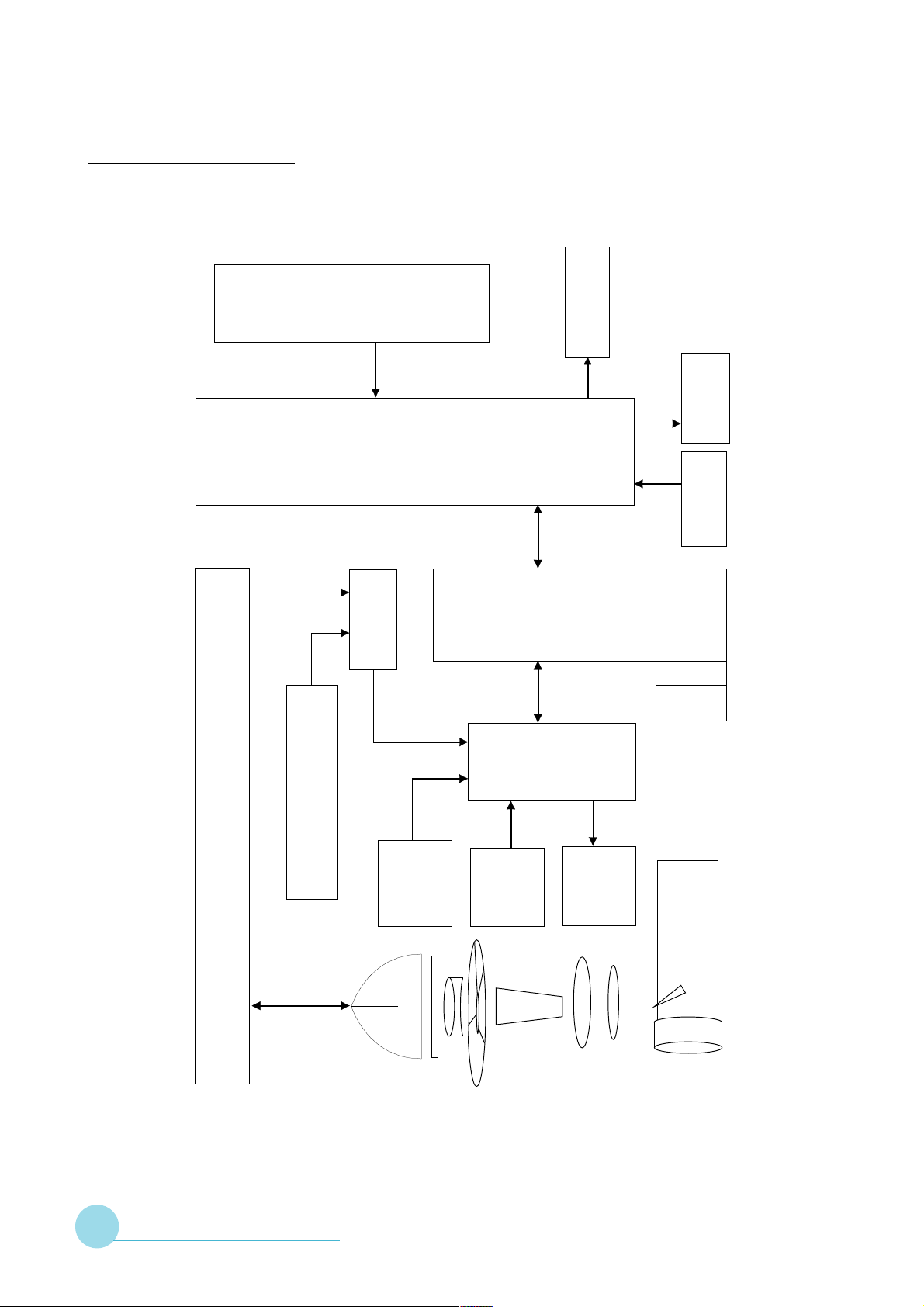
2-1 Block Diagram
Board
Keypa d
Input
Mouse
DVI
Audio
Board
Main
Video
D-sub Output
S-V ideo
Speaker
IR Receiver
Ballast
DC to DC
Inter Lock Switch
Switch
Thermal
Board
Sensor
Board
Board
Thermal
DMD
Fan
DMD
Mirror
Projection Lens
Mirror
SERVICE MANUAL 2 - 2
Hollow Rod
Lamp
UV -IR L3
Color Wheel
Condenser
Condenser
Page 11
EzPro735
EzPro735
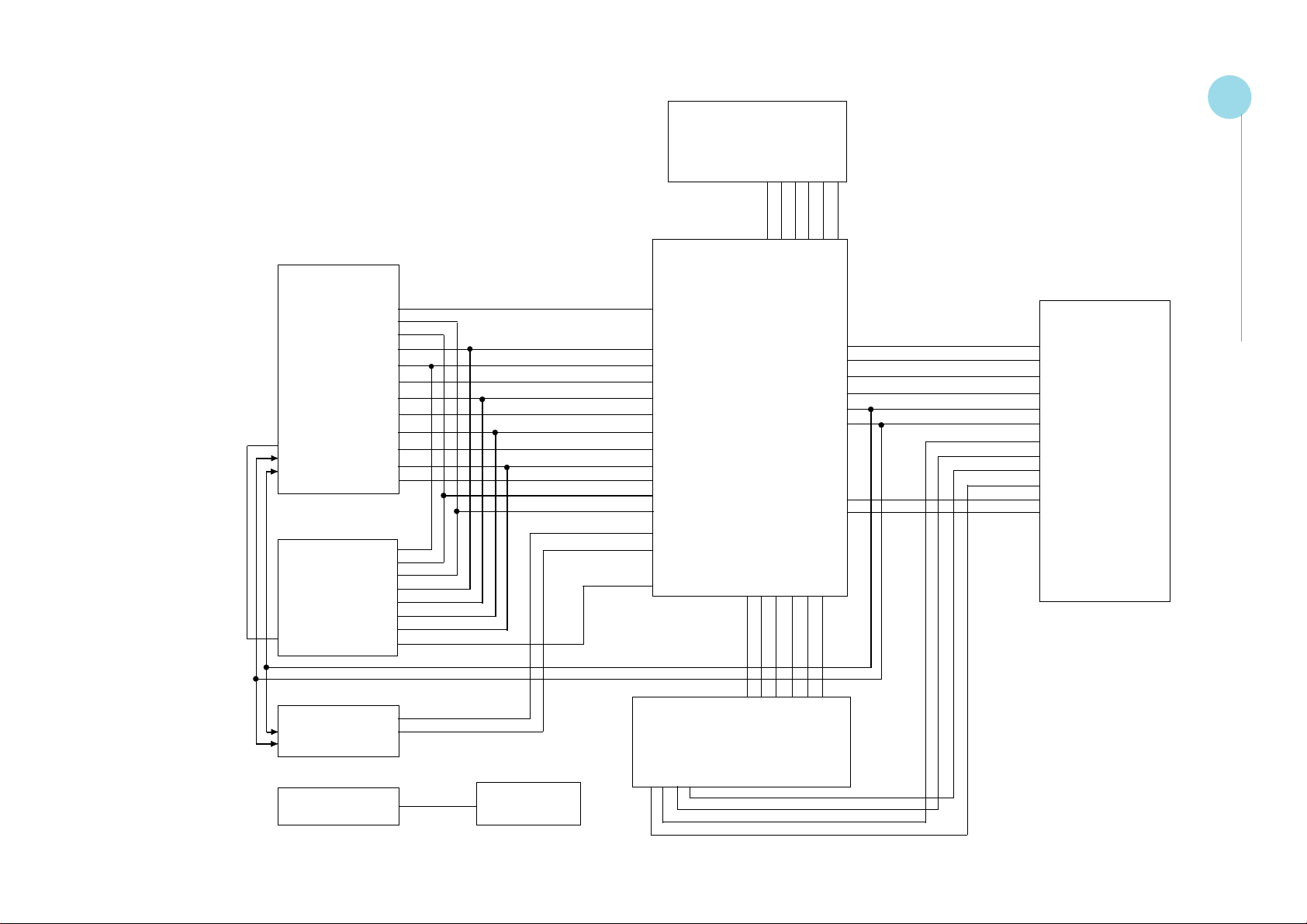
ADC
GCOAST
GVS
GHS
GFBK
GCLK
GBLKSPL
GRE(0..7)
GRO(0..7)
GGE(0..7)
DE
GGO(0..7)
SDA
SCL
GBE(0..7)
GBO(0..7)
Digital Receiver
GCLK
GHS
GVS
GFBK
GRE(0..7)
GGE(0..7)
DE
GBE(0..7)
Switch
Memory
Image Processor
GCOAST
GFBK
GCLK
GBLKSPL
GRE(0..7)
GRO(0..7)
GGE(0..7)
GGO(0..7)
GBE(0..7)
GBO(0..7)
GHS
GVS
Y(0..7)
UV(0..7)
Switch
BOOTWE
A(0..5)
BOOTWE
DRE(0..7)
GGE(0..7)
DBE(0..7)
TEMPER
Sta ndby
RESET
7SEC
A(0..5)
VPPEN
D(0..5)
D(0..5)
VPPEN
ROMOEN
SCL
SDA
TXD
RXD
KEY(1..7)
DCLK
MCLK
ROMOEN
ROMWEN
ROMWEN
DMD Module
DRE(0..7)
GGE(0..7)
DBE(0..7)
TEMPER
SCL
SDA
PWRGOOD
IR-ONOFF
LAMPEN
-RESET
TXD
RXD
SERVICE MANUAL 2 - 3
2-1.1 Main Board Block Diagram
Video
SCL
SDA
Audio
Y(0..7)
UV(0..7)
Speaker
±
Speaker
-RESET
PWRGOOD
IR-ONOFF
LAMPEN
RESET
Sta ndby
7SEC
DCLK
KEY(1..7)
MCLK
MIS
Page 12
EzPro735
EzPro735
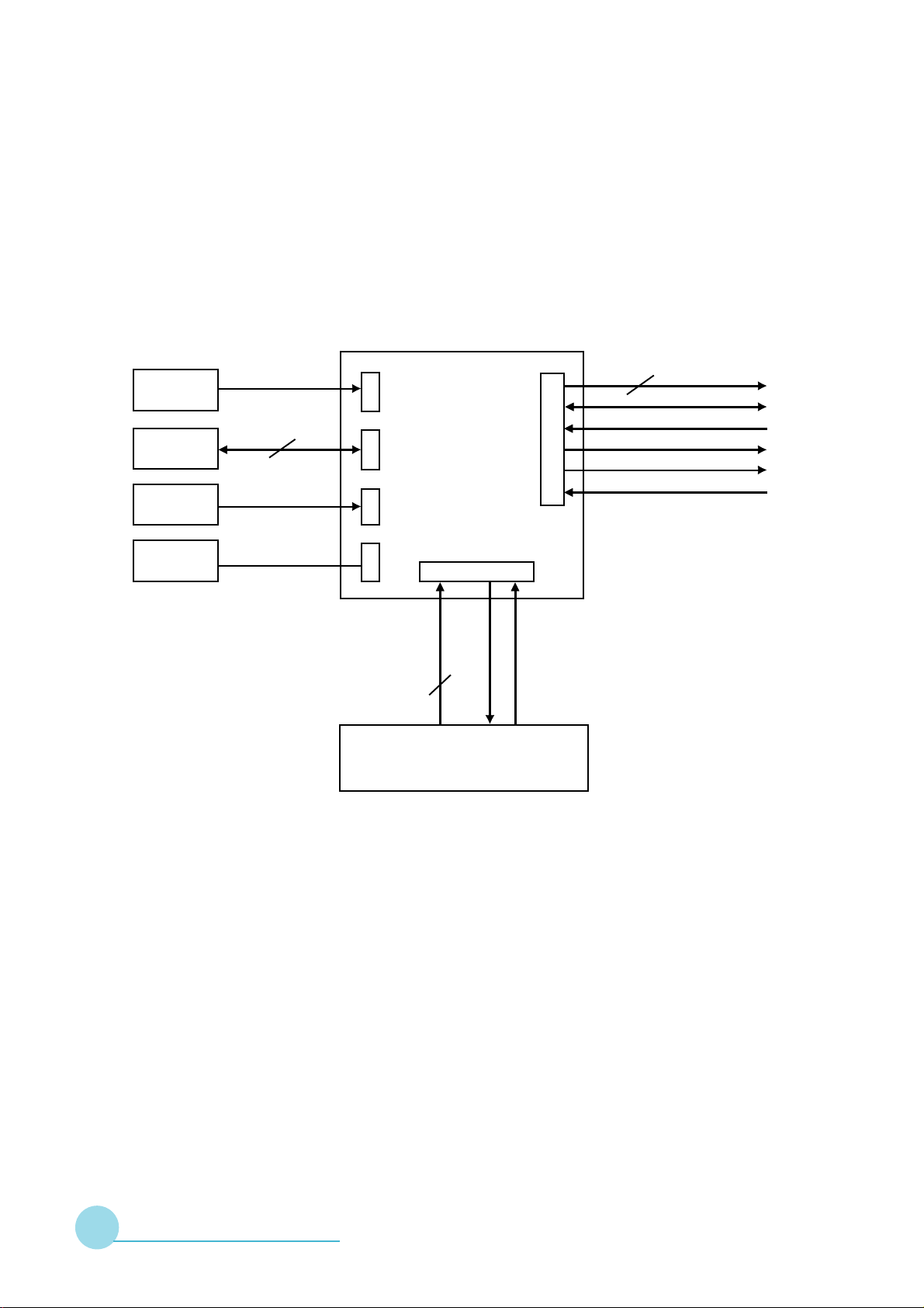
2-1.2 Thermal Board Block Diagram
PHOTO
SENSOR
F AN1-13
THERMAL
SWITCH
THERMAL
SENSOR
THERMAL BOAR D Interface
3P Connector
3P Connector*3
30P Connector
to Formatter
2P Connector
4P Connector*2
14P Connector
+15VSBY
+5VSBY
+3.3VSBY
LAMPEN_OUT
DC TO DC POWER SUPPLY
Board
LAMPLIT_IN
+12V*1
+5V*2
+3.3V*2
GND
LAMPEN (RESETZ)
CWINDEX
LAMPLIT
Power on/off (only 5V, 15V)
SERVICE MANUAL 2 - 4
Page 13
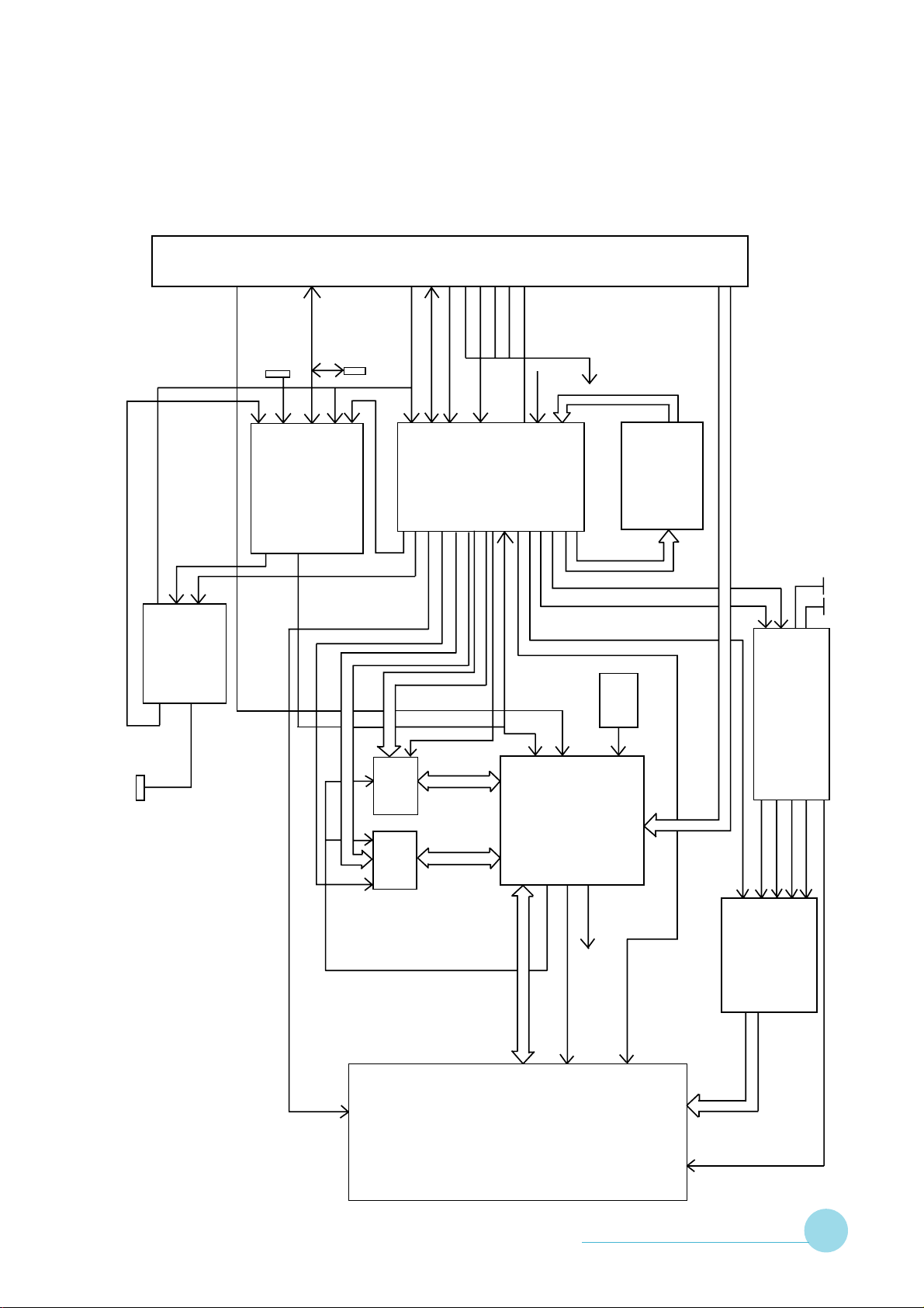
2-1.3 Formatter Board Block Diagram
Customer Interface Connector
HEADER
PROGRAMMING
FLASH
U13
COLOR WHEEL INDEX
VSYNCZ, RESETZ
LAMP CONTROL&STATUS
CWRSTZ
DMD CONTROL
MEMORY CONTROL B
COLOR WHEEL STATUS
CONTROL
WHEEL
COLOR
CLKIN
IIC BUS
HEADER
DOWNLOAD
HITACHI
CONTROLLER
MICRO
SYNCVAL
TFIELD
OLACT
MEMORY ADDRESS B (12)
MEMORY ADD RESS A (12)
ACTDATA
HSYNCZ
VSYNCZ
FPGA
CONTROL
BIAS/RESET CONTROL
DMD CONTROL
PBUS2
MEMORY CONTROL A
EzPro735
EzPro735
DPF2A CONTROL
FPGA CLK
DATA(8)
U504
CONFIG/
BIAS BIN
VOLTAGE ENABLES
U6
ADDRESS(19)
PROM
SEQUENCE
+5V+12V
DRIVE
WHEEL
COLOR
CONTROL
U2
MOTOR
ALLEGRO
A
B
SDRAM
SDRAM
DMD DA T A (0..63)
INPUTCLK
DPF2A
FORMA TTER
SDRAM CLK
DMDCLK
OSC
DAT APA TH
FPGA CLK
CLOCK
VERSET GENERA TION
VCC2, VOFFSET, VBIAS
VRESET
VBIAS
VOFFSET
RESET ASIC
MBIASRST(16)
VCC2(ASIC)
VCC2 (DMD)
DATA (0..63)
0.7”XGA
DMD
SERVICE MANUAL 2 - 5
Page 14
EzPro735
EzPro735
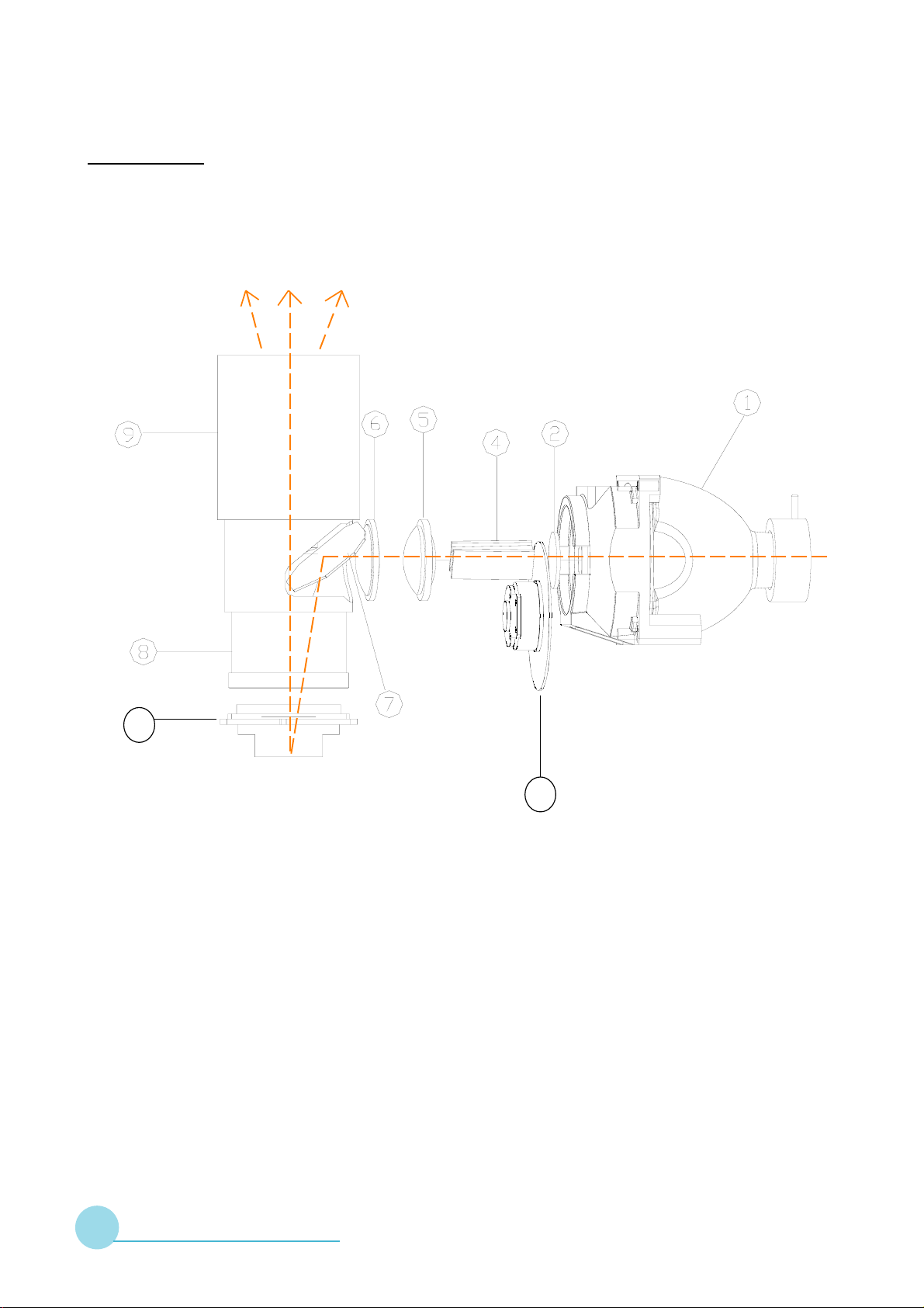
2-2 Optics
2-2.1 Conceptual Drawing
10
3
1. OSRAM Elli ptical Reflector 6. Condenser Lens 2
UHP La mp 120W
7. Enhance M irror
2. UV-IR Filter
8. Field Lens
3. Color Wheel
9. Projection Zoom Lens
4. Hollw Integratin Rod
10. DMD Module
5. Condenser Lens 1
SERVICE MANUAL 2 - 6
Page 15

EzPro735
EzPro735
2-2.2 Basic Functions
◆ Elliptical Reflector The light source.
UHP Lamp 120W
◆ UV-IR Filter Filtering UV -IR out.
◆ Color Wheel Separating the light beam into a nd produce
R.G.B colors.
◆ Hollow Making the light bea m uniform.
Integration Rod
◆ Condenser Lens Condensing the light beam .
◆ Enhance Mirror Folding optical path.
◆ Projection Zoom Lens Projecting i mage on the screen
◆ DMD Module Displaying component.
SERVICE MANUAL 2 - 7
Page 16

Chapter 3
EzPro735
EzPro735
MECHANICAL CONSTRUCTION
This section provides the package and exploded overview, replaceable
parts list and recommendatiom parts list for the portable projector. You can
place an order for correct parts in the recommendation parts list.
SERVICE MANUAL 3 - 1
Page 17
EzPro735
EzPro735
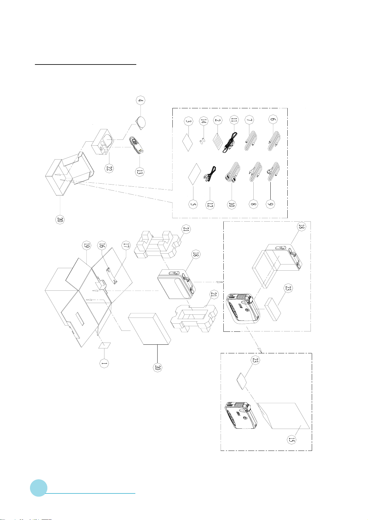
3-1 Package Overview
SERVICE MANUAL 3 - 2
Page 18

EzPro735
EzPro735
3-1.1 Replacement Parts List
metI N/P .veR noitpircseD krameR
1190.20325.53A knalB29*801notraC,lebaL
1-2200.21000.63B seireSPPLrofSU,draCytnarraW
2-2300.50000.63B NPJ,draCytnarraW
3-2300.60000.63B NWT,draCytnarraW
4-2300.90000.63B KH,draCytnarraW
5-2200.01000.63B KU,draCytnarraW
---100.21000.53B mc4.3*8.7ecivreSKUroflebaL
3100.31000.63B seiresPPLrofSU,mroFnoitartsigeRytnarraWdednetxE
4100.10438.63C 537PElaugnilitluMediuGs'resU
5100.20438.63B 537PElaugnilitluMdraCtratSkciuQ
6200.01105.24B oediV-PPLmm0051ACRelbaC
7110.90205.24BM2SHV-SelbaC
8100.51708.24B mm0081ACRotkcaJiniMelbaC
9100.01918.24B
01100.30438.24B M8.1)eulB(AGVot)etihW(IVDelbaC
11100.40438.24B etihWM8.1ACRotIVDelbaC
1-21100.50438.24B 501M8.1CAdroCrewoPelbaC
2-21100.70438.24B )anihC(kcalBM8.1CAdroCrewoPelbaC
3-21140.21518.24B
4-21100.51138.24B )napaJ(kcalB75/65XM8.1droCCAelbaC
5-21100.61138.24B )eporuE(kcalB75/65XM8.1droCCAelbaC
6-21100.71138.24B )KU(kcalB75/65XM8.1droCCAelbaC
---100.20318.24BTRACSretpadA
3138.54 104 00. 2 ArellortnoCetomeR lebaLADFhtiw
41100.10308.64BV5.14#yrettaB
M8.1BUS-D/epyT"A"BSUotP8niDiniMelbaCY
o
)SU(kcalBC
)dnalaeZweN/ailartsuA(kcalBtf015CCAdroCrewoPelbaC
51100.73518.15A mm1.0*004*003gaBDSE
61100.92518.15A xoB-yrraCreppUeldnaH
71100.03518.15A xoB-yrraCrewoLeldnaH
81100.10338.35AgaBgniyrraCtfoS
91100.10338.55A 037PExoBedistuOnotraC
02100.20338.55A xoByrosseccAnotraC
SERVICE MANUAL 3 - 3
Page 19

EzPro735
EzPro735
metI N/P .veR noitpircseD krameR
12100.10338.65AnoihsuC
22100.20338.65A xoByrosseccArofnoititraP
32100.30438.65A esaCtfoSedisnInoihsuC
42100.10000.75AOiSkcaP2 g02reirD
---200.30438.53A erutarepmeT&egatloVhgiHnoituaClebaL
---100.20438.55A tellaProftroppuSrepaP
Note : Mark --- and in red color mean the added or updated item, and item
in blue color is deleted.
SERVICE MANUAL 3 - 4
Page 20
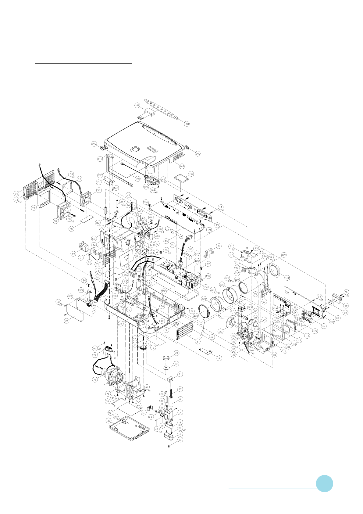
3-2 Exploded Drawing
EzPro735
EzPro735
SERVICE MANUAL 3 - 5
Page 21

EzPro735
EzPro735
3-2.1 Replacement Parts List
metI N/P .veR noitpircseD krameR
1100.60418.53A knalB601*23cepSlebaL
2003.323A1.58A kcalB03*3MhceMnapwercS
3060.221A4.58A 6*2MhceMtalFwercS
4100.10138.25A evitcAllamSrotavelE
5100.20138.25BtroppuSrebbuR
6100.11338.15A 537PErevoCtupnItneV
7100.73138.15AediuGriAtuptuO
8100.93138.15AxiFedoCrewoP
9100.70438.16A lateMteNfoorperiF
01100.50438.25B P04-S-RSnoroPyeKrotavelEroftuCthgiL
11100.30138.24B )B/TotCD(mm0862#P41.A.W
21100.40138.24B )tsallaBotdraoBCD-CD(mm05242#P4.A.W
31100.70338.15A 037PErevoCxoBOI
41.GA500.58 040 AO/IwercS 5.5L*4H*CNU04-4#leetS
51100.10000.15AeiTelbaC
61.91138.15 200 AesaBrotavelE
71100.02138.15BtekcarBrotavelE
81100.12138.15ASProtavelE
91.22138.15 200 AraeGrotavelE
02100.42138.15AtraPedilS
12100.03138.15A tekcarBpoTrotavelE
22100.05138.15ApartSpaC
32100.45138.15AediuGraBhsuP
42100.55138.15A tekcarBediSrotavelE
52100.50338.15AyeKrotavelE
62100.22138.16A gnirpSediSrotavelE
72100.52138.16A gnirpSraeGrotavelE
82200.82138.16AraBhsuP
92100.65138.16A gnirpSraBhsuProtavelE
03100.20338.16CgnisuoHesaB
13100.40438.16A 5.4LwercS81L3MkcitSreppoCnogaxeH
23080.221A1.58A 8*2MhceMnaPwercS
33.58 321A0 060.A 6*3MhceMF/PwercS
SERVICE MANUAL 3 - 6
Page 22

EzPro735
EzPro735
metI N/P .veR noitpircseD krameR
43060.321A1.58A 6*3MhceMnaPwercS
53100.60438.16A 3.62L3MkcitSreppoCnogaxeH
63040.321A1.58A 4*3MhceMnaPwercS
73060.722C1.58A )rehsaWPS/W(roloC6*5.3MhceMnaPwercS
83100.14138.15A revoCnoitcetorPkcolretnI
93100.10438.08D draoBniaMABCP
04100.80138.08A draoBhctiwSABCP
14100.50438.08C 09=DIdraoBrosneSlamrehTABCP
24100.60438.08D 19=DIdraoBrosneSlamrehTABCP
34100.30438.16A hctiwSlamrehTraeNtuCthgiL
44.68 530.24130 AP7.0*4MstuNdaeHpaCxeH
54100.10438.15B ralyMdraoBniaM
64100.52138.25A rebbuRnoitalusnItaeHesuoHpmaL
74100.40438.53A hctiwSkcolretnIroflebaL
84420.221A4.58A 4.2*2MhceMrefaWwercS
94100.60438.25A rebbuRnociliSepiPriA
05.12138.16 300 AredloHhctiwSlamrehT
15.20138.34 300 AhctiwSlamrehT 07
25100.20138.94A01*04*04naF
35100.91138.16A 01*04*04redloHnaF
45100.10438.25A naFllamSrofrebbuR
55100.10438.53AepaTnaFllamS
65041.323A0.58A 41*3MhceMtalFelbuoDwercS
758.94 8013 100.A 51*05*05naFsselhsurBCDNONUS
85100.01338.15A revoCtuptuOtneV
95100.30438.25A naFgiBrofrebbuR
o
06002.323A1.58A kcalB02*3MhceMnaPwercS
16200.01138.32A retliFRI-VUlacitpO w mn556:05Tmm1.1=T57.61=
26100.30138.94A mm051:Lmm51*15HP21-F50DnaFOCCORICSCEDIN
36.40138.15 200 BgnisuoHpmaL
46100.60138.15A epiPdniWrewolB
56100.71518.16A retliFRI-VUroftekcarB
66100.74138.16B lioFmunimulApoTesuoHpmaL
SERVICE MANUAL 3 - 7
Page 23

EzPro735
EzPro735
metI N/P .veR noitpircseD krameR
76100.44138.16A lioFmunimulAesuoHpmaL
86100.54138.16AdleihSepiPdniW
96520.223AY.58A kcalB5.2*2MpaTdaeHtalFwercS
07AW.58 623 060.A kcalB6*6.2MpaTdaeHnaPwercS
17100.20438.15A keePpmaLroftuCthgiL
27002.323A1.58A kcalB02*3MhceMnaPwercS
37A0.68 420.321 AtuNxeH 4.2LP5.0*3M
47900.031RS.78A t9.0*3MrehsaWgnirpS
57.51918.32 400 Amm3.1W021rotcelfeRlacitipillEMARSO
67100.20138.15AredloHpmaL
77.53138.15 200 AtekcarBrotcennoCpmaL
87100.90138.16A reldnaHegnahcxEpmaL
97060.321A1.58A 6*3MhceMnaPwercS
08.58 106 060.32AwercS tekcoSxeH 6*3MhceM
18060.621AW.58A 6*6.2MpaTdaeHnaPwercS
28420.321A0.68A 4.2LP5.0*3MtuNxeH
38100.40338.16AtuCthgiL
48.10138.15 200 ArevoCenignE
58100.30438.15AralyMtuCthgiL
68100.60138.25A rebbuR1sneL-revoCenignE
78100.12138.25A rebbuR2sneL-revoCenignE
88100.10138.16AkniStaeHDMD
98100.70138.16B )draoBniaMrof(troppuS-LdraoBDMD
09060.321A1.58A 6*3MhceMnaPwercS
19080.221A1.58A 8*2MhceMnaPwercS
29230.FA1A1.58A 4/1x23-6#hceMnaPwercS
39050.221D1.58A rehsaW/W(5*2MhceMnaPwercS & )0.5
49A0.58 321 060.AwercS F/P 6*3MhceM
59100.10138.75A evisehdAnoitcudnoCtaeH
69200.71138.32A mm1.62:L,wolloH,repaT,doRgnitargetnI
79200.91138.32C 301B25W501G001R F leehWroloCmm44
89110.60138.32A 1sneLresnednoClacirehpsA F mm7.6:Tmm12
99100.60338.32A 2sneLresnednoClacirehpsA F mm00.9:Tmm22
SERVICE MANUAL 3 - 8
Page 24

EzPro735
EzPro735
metI N/P .veR noitpircseD krameR
001100.80138.25A rebbuRsneL-1esaBenignE
101100.31138.16AIesaBenignE
201100.41138.16AIIesaBenignE
301100.32138.16A tsujdAdoRrofetalPgnirpS
401100.14138.16AgnirpSdexiFdoR
501200.10138.67A draoBrosneSotohPYSSA
601060.321A1.58A 6*3MhceMnaPwercS
701080.325A3.58A 8*3MhceMdaeHpaCwercS
801050.221D1.58A rehsaW/W(5*2MhceMnaPwercS & )0.5
901050.221A1.58A 5*2MhceMnaPwercS
011200.20138.32A mm7.0:TnogyloProrriMecafruStnorF
111.31138.53 300 A76J-M3mm21.51*02rorriMrofepaTediShtoB
211.81138.16 200 AAGXrofredloHrorriM
31110D.MD818.84A AGX"7.0slexiP867**4201DMD
411100.10238.15A AGX"7.0rofredloHDMD
511100.10718.25AremotsalEarbeZ
611200.40138.25A rebbuRredloHDMD
711300.90138.25A rebbuRkraMDMD
811100.10238.08B draoBrettamroFABCP
911200.10138.32A 4.2:#/FsneLevitcejbOnoitcejorP
021100.60338.15AgniRsucoF
121100.21338.15AgniRmooZ
221100.30138.25A rebbuRsneLtcejorP
321040.10438.16A 3D-4*2MhceMtalFwercS
421030.221A4.58A 3*2MhceMtalFwercS
521100.10438.57A eludoMpaCsneLYSSA
621100.13138.15AralyMCD-CD
721100.83138.15A redloHdraoBCD-CD
821.20138.57 200 AdraoBCD-CDYSSA
921100.16000.15AteviRcitsalP w L3-RS0.3
031110.31138.15A revoCtnemecalpeRpmaL
131100.34138.16A )revoCtnemecalpeR(reppoCkniStaeH
231100.11508.16A kcalB4-8*3MhceMnaPwercS
SERVICE MANUAL 3 - 9
Page 25

EzPro735
EzPro735
metI N/P .veR noitpircseD krameR
331100.50438.15AralyMtsallaB
431200.24138.15A )LU-L1-HF(revoCesuF
531100.10138.57A CPF+tsallaBYSSA
631060.722C1.58A )rehsaWPS/W(6*5.3MhceMnaPwercS
731100.20438.16A etalPdnuorGtsallaB
831100.30438.08F draoBlamrehTABCP
931100.80138.16A troppuSdraoBlamrehT
041050.221A1.58A 5*2MhceMnaPwercS
141100.10138.14A eroCCPFdapyeK
241110.10338.16BrevoCpoT
341100.30338.16AredloHrekaepS
441.621A1.58 030 AMhceMnaPwercS 3*6.2
541100.50338.16A reppoCkniStaeH
641100.31338.15ArevoCsneLRI
741100.50138.08A draoBrevieceRRIABCP
841100.10338.67BdapyeKYSSA
941060.321A1.58A 6*3MhceMnaPwercS
051100.10438.94A mm11*2.82*04mho8W2rekaepS
151100.15138.15AralyMdraoBRI
251100.60438.15BdleihSrekaepS
351100.60438.24A )DBniaMotDBRI(mm08262#P3.A.W
Note : Mark --- and in red color mean the added or updated item, and item
in blue color is deleted.
SERVICE MANUAL 3 - 10
Page 26

EzPro735
EzPro735
3-3 Recommendation Spare Parts List
metI N/P .veR noitpircseD epyT
1100.72438.07A )AMR(eludoMgnisuoHesaBMC
2100.11338.15ArevoCtupnItneVMC
3100.10000.15AeiTelbaCMC
4100.70338.15ArevoCxoBOIMC
5100.50438.07A eludoMrosneSlamrehTYSSAMC
6100.73138.15AediuGriAtuptuOMC
7100.93138.15AxiFdroCrewoPMC
8100.05138.15ApartSpaCMC
9100.14138.15A revoCnoitcetorPkcolretnIMC
01100.60438.25A rebbuRnociliSepiPriAMC
11100.65138.16A gnirpSraBhsuProtavelEMC
21100.20138.94A01*04*04naFMC
31100.10438.25A naFllamSrofrebbuRMC
4138.94 801 100.A 51*05*05naFMC
51100.01338.15A revoCtuptuOtneVMC
61100.30438.25A naFgiBrofrebbuRMC
71100.30138.94A mm051:Lmm51*15HP21-F50DnaFOCCORICSCEDINMC
81100.92438.07A )AMR(eludoMenignEYSSAWS
91200.10138.67A draoBrosneSotohPYSSAMC
0210D.MD818.84A AGX"7.0slexiP867*4201DMDWS
12200.40138.25A rebbuRredloHDMDMC
22300.90138.25A rebbuRkraMDMDMC
32100.10238.08B draoBrettamroFABCPWS
42100.10438.57A eludoMpaCsneLYSSAMC
52100.10138.75A evisehdAnoitcudnoCtaeHMC
62100.41438.07A eludoMCDotCDYSSAWS
72100.13438.07A )AMR(eludoMgnisuoHpmaLWS
82100.51438.07A revoCtnemecalpeRpmaLYSSAMC
92100.50438.15AralyMtsallaBMC
03100.03438.07A )AMR(eludoMtsallaBYSSAWS
13100.62438.07A )AMR(eludoMdraoBniaMYSSAWS
23100.80138.08A draoBhctiwSABCPWS
33100.30438.16A hctiwSlamrehTraeNtuCthgiLMC
SERVICE MANUAL 3 - 11
Page 27

EzPro735
EzPro735
metI N/P .veR noitpircseD epyT
43100.82438.07A )AMR(eludoMrevoCpoTYSSAMC
53100.10438.94A mm11*2.82*04mho8W2rekaepSMC
63100.60438.15BdleihSkaepSMC
73100.15138.15AralyMdraoBRIMC
83100.31338.15ArevoCsneLRIMC
93100.50138.08A draoBrevieceRRIABCPWS
04100.60438.24A )draoBniaMotRI(mm08262#P3.A.WMC
14100.30438.08F draoBlamrehTABCPWS
24100.50438.08C 09=DIdraoBrosneSlamrehTABCPWS
34100.60438.08D 19=DIdraoBrosneSlamrehTABCPWS
44100.10438.PSA )AMR(eludoMpmaLMC
54100.11508.16A kcalB4-8*3MhceMnaPwercSMC
64040.10438.16A 3D-4*2MhceMtalFwercSMC
74100.40438.16A 5.4LwercS81L3MkcitSreppoCnogaxeHMC
84.GA500.58 040 A*CNU04-4#leetSO/IwercS 5.5L*4H MC
94041.323A0.58A kcalB41*3MhceMF/PwercSMC
05A0.58 321 060.AwercS F/P 6*3MhceMMC
15050.221A1.58A 5*2MhceMnaPwercSMC
25080.221A1.58A 8*2MhceMnaPwercSMC
35040.321A1.58A 4*3MhceMnaPwercSMC
45060.321A1.58A 6*3MhceMnaPwercSMC
55.621A1.58 030 AhceMnaPwercS 3*6.2M MC
65230.FA1A1.58A 4/1*23-6#hceMnaPwercSMC
75002.323A1.58A kcalB02*3MhceMnaPwercSMC
85003.323A1.58A kcalB03*3MhceMnaPwercSMC
95060.722C1.58A )rehsaWS/W(roloC6*5.3MhceMnaPwercSMC
06050.221D1.58A rehsaWS/W(5*2MhceMnaPwercS w )0.5MC
16080.325A3.58A 8*3MhceMdaeHpaCwercSMC
26420.221A4.58A 4.2*2MhceMrefaWwercSMC
36030.221A4.58A 3*2MhceMtalFwercSMC
46060.221A4.58A 6*2MhceMtalFwercSMC
56.58 32106 060.AwercS tekcoSxeH 6*3MhceMMC
66060.621AW.58A 6*6.2MpaTdaeHnaPwercSMC
SERVICE MANUAL 3 - 12
Page 28

EzPro735
EzPro735
metI N/P .veR noitpircseD epyT
76520.223AY.58A kcalB5.2*0.2MepaTdaeHrefaWwercSMC
86530.24130.68A P7.0*4MtuNdaeHpaCxeHMC
96420.321A0.68A 4.2LP5.0*3MtuNxeHMC
07900.031RS.78A t9.0*3MrehsaWgnirpSMC
17100.42438.07A tamroF537PEhtiwlebaLnotraCyssAMC
27110.90205.24BM2SHV-SelbaCMC
37100.51708.24B mm0081ACRotkcaJiniMelbaCMC
47200.01105.24B mm0051ACRelbaCMC
57100.01918.24B M8.1BUS-D/epyT"A"BSUotP8niDiniMelbaCYMC
67100.30438.24B M8.1)eulB(AGVot)etihW(IVDelbaCMC
77100.40438.24B etihWM8.1ACRotIVDelbaCMC
87100.50438.24B 501M8.1CAdroCrewoPelbaC
o
)SU(kcalBCMC
97.10438.54 200 ArellortnoCetomeR lebaLADFhtiw 537PEMC
08100.92518.15A xoB-yrraCreppUeldnaHMC
18100.03518.15A xoB-yrraCrewoLeldnaHMC
28100.73518.15A mm1.0*004*003gaBDSEMC
38100.10338.35A gaBgniyrraCtfoSMC
48100.10338.55A xoBedistuOnotraCMC
58100.20338.55A xoByrosseccAnotraCMC
68100.10338.65AnoihsuCMC
78100.20338.65A xoByrosseccArofnoititraPMC
88.30438.53 200 AerutarepmeT&egatloVhgiHnoituaClebaLMC
98200.21000.63B seireSPPLrofSU,draCytnarraWMC
09100.31000.63B seireSPPLrofSU,mroFnoitartsigeRytnarraWdednetxEMC
19100.10438.63C 537PElaugnilitluMlaunaMs'resUMC
29100.20438.63B 537PElaugnilitluMdraCtratSkciuQMC
Note : SW = Swap Spare Parts, CM = Consume Spare Parts. You can place an order
for swap or consume spare parts to do replacement. Or just return swap spare
parts back for repair, but consume spare parts is not acceptable for repair or
return.
SW is repairable, when its defective please return back the defective but
complete parts to swap for good parts. Regarding CM, its not repairable and you
should give the order to do replacement and discard the defective parts directly.
The recommendation spare parts list is built for the convenience of disassembly
procedure. If there is any comment or recommendatin on the item of SW or CM,
please let us know.
SERVICE MANUAL 3 - 13
Page 29
EzPro735
EzPro735
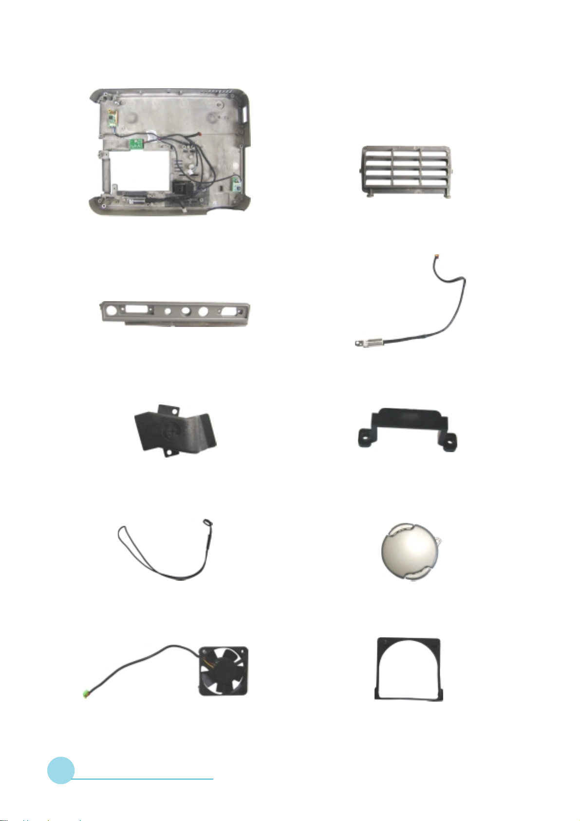
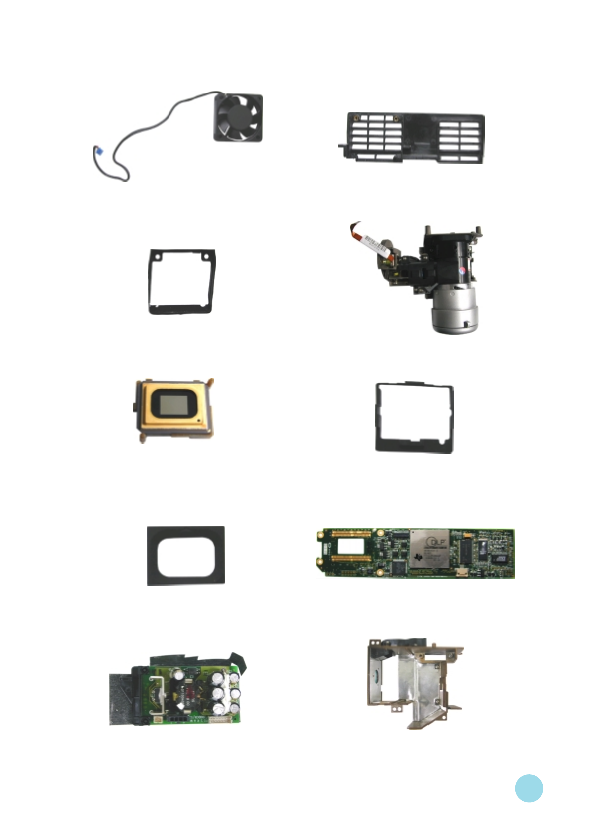
70.83427.001 Base Housing Module (RMA)
51.83307.001 IO Box Cover
51.83137.001 Output Air Guide 51.83139.001 Power Code Fix
51.83311.001 Vent Input Cover
70.83405.001 ASSY Thermal Sensor Module
51.83150.001 Cap Strap
49.83102.001 Fan 40*40*10
SERVICE MANUAL 3 - 14
75.83401.001 ASSY Lens Cap Module
52.83401.001 Rubber for Small Fan
Page 30
EzPro735
EzPro735
49.83108.001 Fan 50*50*15
52.83403.001 Rubber for Big Fan
48.818DM.D01 DMD 1024*768 Pixels
0.7 XGA
51.83310.001 Vent Output Cover
70.83429.001 Engine Module (RMA)
52.83104.002 DMD Holder Rubber
52.83109.003 DMD Mark Rubber
70.83414.001 ASSY DC to DC Module
80.83201.001 PCBA Formatter Board
70.83431.001 Lamp Holder Module (RMA)
SERVICE MANUAL 3 - 15
Page 31

EzPro735
EzPro735
70.83415.001 ASSY Lamp Replacement Cover
70.83430.001 Ballast Module (RMA)
51.83405.001 Ballast Mylar
70.83426.001 Main Board Module
61.83403.001 Light Cut Near Thermal Switch
80.83108.001 PCBA Switch Board
70.83428.001 ASSY Top Cover Module
(RMA)
SERVICE MANUAL 3 - 16
49.83401.001 Speaker 2W 8ohm 40*28.2*11mm
51.83313.001 IR Lens Cover
Page 32

EzPro735
EzPro735
80.83105.001 PCBA IR Receiver Board
SP.83401.001 Lamp Module (RMA)
42.83406.001 W.A. 3P #26 280mm
80.83403.001 PCBA Thermal Board
80.83405.001 PCBA Thermal Sensor Board
ID=90
49.83103.001 NIDEC SCIROCCO Fan
51*15mm L:150mm
80.83406.001 PCBA Thermal Sensor Board
ID=91
52.83406.001 Air Pipe Silicon Rubber
SERVICE MANUAL 3 - 17
Page 33

EzPro735
EzPro735
61.80511.001 Screw Pan Mech M3*8-4 Black
61.83404.001 Hexagon Copper Stick M3 L18
Screw L4.5
85.0A323.140 Screw P/F Mech M3*14 Black
61.83401.040 Screw Flat Mech M2*4-D3
85.005AG.040 Screw I/O #4-40*H4*L5.5
85.0A123.060 Screw P/F Mech M3*6
85.1A122.050 Screw Pan Mech M2*5
85.1A123.040 Screw Pan Mech M3*4
SERVICE MANUAL 3 - 18
85.1A122.080 Screw Pan Mech M2*8
85.1A123.060 Screw Pan Mech M3*6
Page 34

EzPro735
EzPro735
85.1A126.030 Screw Pan Mech M2.6*3
85.1A323.200 Screw Pan Mech M3*20 (Black)
85.1C227.060 Screw Pan Mech M3.5*6 Color
(W/SP Washer)
85.1A1AF.032 Screw Pan Mech #6-32*1/4
85.1A323.300 Screw Pan Mech M3*30 (Black)
85.1D122.050 Screw Pan Mech M2*5
(W/Washer w5.0)
85.4A122.024 Screw Wafer Mech M2*2.4
85.WA126.060 Screw Pan Head Tap M2.6*6
85.4A122.060 Screw Flat Mech M2*6
85.YA322.025 Screw Wafer Head Tape
M2.0*2.5 Black
SERVICE MANUAL 3 - 19
Page 35

EzPro735
EzPro735
85.0A123.024 Hex Nut M3*0.5P L2.4
42.50209.011 S-VHS Cable
42.50110.002 RCA Cable 1500mm
70.83424.001 Carton Label
42.80715.001 Cable Mini Jack to RCA
1800mm
42.83403.001 Cable DVI(White) to
VGA(Blue) 1.8m
42.83404.001 Cable DVI to RCA 1.8m White
42.83405.001 Cable Power Cord AC
1.8M (US)
SERVICE MANUAL 3 - 20
42.81910.001 Y Cable Mini Din 8P to USB
A Type/D-SUB 1.8m
55.83301.001 Carton Outside Box
Page 36

EzPro735
EzPro735
45.83401.002 Remote Controller
53.83301.001 Soft Carrying Bag
51.81537.001 ESD Bag 300*400*0.1mm
55.83302.001 Carton Accessory Box
56.83301.001 Cushion
35.83403.002 Label Caution High Voltage
& Temperature
36.83402.001 Quick Start Card
Multilingual EP735
36.00012.002 Warranty Card, US for LPP
SERVICE MANUAL 3 - 21
Page 37

EzPro735
EzPro735
36.00013.001 Extended Warranty Registration
Form, US for LPP
36.83401.001 Users Manual
Multilingual EP735
SERVICE MANUAL 3 - 22
Page 38

Chapter 4
EzPro735
EzPro735
PROCEDURE OF DISASSEMBLY
This section provides disassembly procedures for EP735 Micro Portable
XGA DLP Projector. Before you begin a ny of these procedures, be sure to turn
off the power, computer system, and other attached devices; then disconnect
the power cable from the electronically outlet. Moreover, when you disasse mble
the projector, be sure to put the screws in a safe place and separate them
according to grouping.
SERVICE MANUAL 4 - 1
Page 39

EzPro735
EzPro735
Tools Needed :
Long Nose Nipper (Left)
Angle Cutting Ni pper (Right)
Screw Bit (+) : 107, 102, 101 (from top to bottom)
Hex Sleeves 5mm (T op)
Screw Bit (-) 101
SERVICE MANUAL 4 - 2
Page 40

4-1 Disassemble Top Cover and Speaker
1
Base Housing
EzPro735
EzPro735
Lens Cap
1
1
1. Take off Lens Cap. Unscrew three long screws on the rear side of Base Housing and one
screw beside Base Housing.
2. Lift up Top Cover and unplug three wires from Main Board to remove Top Cover.
Mylar
4
IR Receiver Board
5
IR Board W ire
2
Top Cover
2
Speaker
Speaker Holder
3. Unscrew two screws of Speaker Holders to remove Speaker.
4. Unscrew one screw on IR Receiver Board to remove IR Receiver Board and Mylar.
5. Unplug IR Board Wire.
3
SERVICE MANUAL 4 - 3
Page 41

EzPro735
EzPro735
4-2 Disassemble Main Board and DC-DC Module
Main Board
M/B Mylar
2
3
IO Box Cover
1
3
1. Unscrew four screws on Main Board.
2. Disconnect the connector and re move M ain Board with IO Box Cover from
Base Housing.
3. Unscrew four hex screws to remove IO Box Cover from Main Board, and
tear off M ain Board Mylar.
SERVICE MANUAL 4 - 4
Page 42

DC-DC Module
EzPro735
EzPro735
4
4. Unscrew one screw and unplug three wire s to re move DC-DC Module.
DC-DC Board
6
DC-DC Mylar
DC-DC
Board
Holder
5
5. Unscrew two screws a nd two Hex Nuts to remove DC-DC Board Holder.
6. Tear off DC-DC Mylar.
SERVICE MANUAL 4 - 5
Page 43

EzPro735
EzPro735
4-3 Disassemble Engine, Formatter Board and Thermal Board
1
1
2
1. Unplug seven wires.
2. Unscrew four screws on Eengine Module to remove Engine Modulet.
SERVICE MANUAL 4 - 6
Page 44

EzPro735
EzPro735
DMD Holder Rubber
5
DMD Holder
4
3
Thermal Board
DMD
Module
4
Formatter Board
Heat Sink
6
3. Unplug one wire, then push forward a nd take of f Thermal Board.
4. Unscrew four screws of Frmatter Board, a nd unplug FPC to re move Formatter Module.
5. Remove DMD Holder Rubber and DMD Holder.
6. Unscrew two screws on DMD Heat Sink to take of f DMD Module.
SERVICE MANUAL 4 - 7
Page 45

EzPro735
EzPro735
7
7. Unscrew two screws of Thermal Board Support to remove it.
SERVICE MANUAL 4 - 8
Page 46

4-4 Disassemble Ballast Module
5
Ballast
EzPro735
EzPro735
Ballast Mylar
4
2
Base Housing
1
Ballast Wire
1. Unscrew two screws a nd unplug Ballast wire.
2. Unscrew two screws on Ballast, two screws on Power Cord Fix and one screw of
Ground Plate.
2
2
Power Cord
Fix
3. Take off Bala st Module from Ba se Housing.
4. Unscrew one screw to remove Ground Plate from Balla st.
5. Unplug one wire a nd tear of f Ballast Mylar.
SERVICE MANUAL 4 - 9
Page 47

EzPro735
EzPro735
4-5 Disassemble Fan Modules
Small Fa n
1
3
V ent Output
Module
2
1. Unscrew two screws to remove Small Fan Module.
2. Unscrew two screws to remove Vent Output Module.
3. Take off Vent Input Cover a nd Push Bar.
Vent
Input
Cover
3
Push Bar
4. Unscrew two screws to remove Fan Holder from samll Fan.
5. Take of f Rubber.
SERVICE MANUAL 4 - 10
5
Rubber
4
Fan Holder
Page 48

Vent Output Cover
Rubber
EzPro735
EzPro735
6
Brushless Fan
6. Unscrew two screws to remove Brushless Fan a nd Rubber from Vent Output Cover.
SERVICE MANUAL 4 - 11
Page 49

EzPro735
EzPro735
4-6 Disassemble Lamp Module
1
Lamp Holder Module
2
Lamp Repla cement Cover
1. Loose two screws to remove Lamp Repla ce ment Cover.
2. Unscrew three screws to pull out Lamp Holder Module.
Lamp Housing
4
Base Housing
3
Ar Pipe
3. Turn over Base Housing, unscrew two screws and remove Output Air Guide and Air Pipe.
4. Unscrew three screws to remove Lamp Housing.
Output Air Guide
SERVICE MANUAL 4 - 12
Page 50

EzPro735
EzPro735
Lamp Housing
5. Unscrew two screws to remove Light Cut.
Fan
5
Light Cut
Blower Wind Pipe
6
7
6. Unscrew four screws to remove Blower Wind Pipe.
7. Unscrew one screw a nd one Hex Nut to remove Fan.
SERVICE MANUAL 4 - 13
Page 51

EzPro735
EzPro735
4-7 Disassemble Switch Board and Thermal Sensor Board
Switch Board
1
2
Thermal
Sensor Board
Base Housing
Light Cut
Thermal Switch
Thermal Sensor Board
4
3
1. Unscrew one screw to remove Switch Board.
2. Unscrew one screw to remove one Thermal Sensor Board.
3. Unscrew one screw to remove a nother Thermal Sensor Board.
4. Unscrew one screw to remove Light Cut a nd Thermal Switch.
SERVICE MANUAL 4 - 14
Page 52

Chapter 5
EzPro735
EzPro735
FUNCTION OF BOARDS
This section provides each connector location on boards, signal and
function of each board. They will be useful for your detecting the defective
boards.
SERVICE MANUAL 5 - 1
Page 53

EzPro735
EzPro735
5-1 Main Board
5-1.1 The locations of Connectors
JP4
J2
J1
J6
JP6
J5
JP1
J4
CON1
JP2
5-1.2 J6 : Audio-In Connector
#niP emaNlangiS noitpircseD
1DNGdnuorG
2R_OIDUAtupnIlennahCthgiRoiduA
3L_OIDUAtupnIlennahCtfeLoiduA
4.C.NnoitcennoCoN
5.C.NnoitcennoCoN
SERVICE MANUAL 5 - 2
Page 54

5-1.3 J1 : DVI Input Connector
#niP emaNlangiS noitpircseD
1-2XTataDtimsnarT
2+2XTataDtimsnarT
3dleihS4/2dnuorG
4-4XTnoitcennoCoN
5+4XTnoitcennoCoN
6KLCCDDkcolCCDD
7TADCDDataDCDD
8NICNYSVtupnI.cnySlacitreVgolanA
EzPro735
EzPro735
9-1XTataDtimsnarT
01+1XTataDtimsnarT
11dleihS3/1dnuorG
21-3XTnoitcennoCoN
31+3XTnoitcennoCoN
41CCV_CPrewoPV5+
51DNGdnuorG
61PHV5+
71-0XTataDtimsnarT
81+0XTataDtimsnarT
91dleihS5/0dnuorG
02-5XTV5+
12+5XTataDtimsnarT
22dleihSKLCdnuorG
32+CXTataDlaireS
42-CXTataDlaireS
52R_golanAtupnIlangiSdeRgolanA
62G_golanAtupnIlangiSneerGgolanA
72B_golanAtupnIlangiSeulBgolanA
82NICNYSHtupnI.cnySlatnoziroHgolanA
92DNGdnuorG
SERVICE MANUAL 5 - 3
Page 55

EzPro735
EzPro735
5-1.4 CON1 : VGA-Out Connector
#niP emaNlangiS noitpircseD
1TUO-RtuptuO.cnySdeR
2TUO-GtuptuO.cnySneerG
3TUO-BtuptuO.cnySeulB
4.C.NnoitcennoCoN
5DNGdnuorG
6DNGdnuorG
7DNGdnuorG
8DNGdnuorG
9.C.NnoitcennoCoN
01DNGdnuorG
11.C.NnoitcennoCoN
21.C.NnoitcennoCoN
31TUO_HtuptuO.cnySlatnoziroH
41TUO_VtuptuO.cnySlacitreV
51.C.NnoitcennoCoN
5-1.5 J2 : RS232 Connector
#niP emaNlangiS noitpircseD
1-DBSUlangiS-BSUesuoMetomeR
2+DBSUlangiS+BSUesuoMetomeR
31CRTD
4DNGdnuorG
5CSTRdneSottseuqeR
61CRTD
7CDXTtupnIataDtimsnarTCP
8CDXRataDevieceR
SERVICE MANUAL 5 - 4
Page 56

5-1.6 JP6 : Output Interface Connector
#niP emaNlangiS noitpircseD
1DNGdnuorG
2BTSV5+rewoPybnatSV5+
3DNGdnuorG
4BTSV5+rewoPybnatSV5+
5DNGdnuorG
6IV3.3+IV3.3+
7DNGdnuorG
8IV3.3+IV3.3+
9DNGdnuorG
EzPro735
EzPro735
01IV3.3+IV3.3+
11DNGdnuorG
21IV3.3+IV3.3+
31DNGdnuorG
41IV3.3+IV3.3+
51DNGdnuorG
61.C.NnoitcennoCoN
71YBDNATS.cnySybdnatS
81RREPMETrorrEerutarepmeT
91FFONO_RIlortnoCybdnatSlortnoCetomeR
02FFONO_DELffO/nODELybdnatS
12DNGdnuorG
22OTESER-.cnySteseR
32DOOGRWPdooGrewoP
42DNGdnuorG
52DLEIFTlangiSdleiF
62XEDNIWCxednIleehWroloC
72ZOCNYSVCNYSlacitreV
82DNGdnuorG
92ATADTCAelbanEataD
03DNGdnuorG
SERVICE MANUAL 5 - 5
Page 57

EzPro735
EzPro735
#niP emaNlangiS noitpircseD
13OKLCDtuptuOkcolCataD
23DNGdnuorG
331DBataDeulB
433DBataDeulB
53DNGdnuorG
635DBataDeulB
737DBataDeulB
83DNGdnuorG
931DRataDdeR
043DRataDdeR
14DNGdnuorG
245DRataDdeR
347DRataDdeR
44DNGdnuorG
540DGataDneerG
642DGataDneerG
74DNGdnuorG
844DGataDneerG
946DGataDneerG
05DNGdnuorG
15IV21+V21+
25DNGdnuorG
35IV21+V21+
45DNGdnuorG
55IV21+V21+
65DNGdnuorG
75IV21+V21+
85DNGdnuorG
95IV5+V5+
06DNGdnuorG
SERVICE MANUAL 5 - 6
Page 58

#niP emaNlangiS noitpircseD
16IV5+V5+
26DNGdnuorG
36IV5+V5+
46DNGdnuorG
56IV5+V5+
66DNGdnuorG
7675X/65XtceteD75Xro65X
86EKOPSsutatSAGPF
96#NWOD_TUHS.cnySnwoD-tuhS
EzPro735
EzPro735
07DNGdnuorG
17ADSataDlaireS
27LCSkcolClaireS
37DNGdnuorG
47CNYSPMAL.cnySpmaL
57TILPMALtiLpmaL
67TSTXEDNIWCtsuahxEleehWroloC
77LAVCNYSV3.3+
87DNGdnuorG
97ZOCNYSHCNYSlatnoziroH
08TCALOlennahCniaM
18DNGdnuorG
28DNGdnuorG
380DBataDeulB
482DBataDeulB
58DNGdnuorG
684DBataDeulB
786DBataDeulB
88DNGdnuorG
980DRataDdeR
092DRataDdeR
SERVICE MANUAL 5 - 7
Page 59

EzPro735
EzPro735
#niP emaNlangiS noitpircseD
194DRataDdeR
296DRataDdeR
39DNGdnuorG
49DNGdnuorG
591DGataDneerG
69DNGdnuorG
793DGataDneerG
895DGataDneerG
99DNGdnuorG
0017DGataDneerG
5-1.7 J4 : S_VHS Connector
#niP emaNlangiS noitpircseD
1DNGdnuorG
2DNGdnuorG
3AMULtupnIlangiSecnanimuL
4AMORHCtupnIlangiSecnanimorhC
5-1.8 J5 : RCA JACK Connector
#niP emaNlangiS noitpircseD
1PMOCtupnIoediVetisopmoC
2DNGdnuorG
SERVICE MANUAL 5 - 8
Page 60

5-1.9 JP1 : To Keypad
#niP emaNlangiS noitpircseD
1PUlortnoCpUdapyeK
2NWODlortnoCnwoDdapyeK
3YBDNATSlortnoCybdnatSdapyeK
4TFELlortnoCtfeLdapyeK
5THGIRlortnoCthgiRdapyeK
6UNEMlortnoCuneMdapyeK
7RETNElortnoCretnEdapyeK
81PMAL_DELDELpmaL
EzPro735
EzPro735
91YEK_DELffO/nOneerGDEL
011PMET_DELDELerutarepmeT
111FFONO_DELDELybdnatS
21DNGdnuorG
31DNGdnuorG
41DNGdnuorG
5-1.10 JP2 : Speaker
#niP emaNlangiS noitpircseD
1+REKAEPS+rekaepSoT
2-REKAEPS-rekaepSoT
5-1.11 JP4 : IR Receiver Connector
#niP emaNlangiS noitpircseD
1R_RIrevieceRRI
2DNGdnuorG
3BTSV5+rewoPybdnatSV5+
SERVICE MANUAL 5 - 9
Page 61

EzPro735
EzPro735
5-2 Formatter Board
5-2.1 The locations of Connectors
JP5
JP1
5-2.2 J502 : To Color Wheel Connector
#niP emaNlangiS noitpircseD
1RTCWClangiSevirDrotoMleehWroloC
2C1TWClangiSevirDrotoMleehWroloC
3C2TWClangiSevirDrotoMleehWroloC
4C3TWClangiSevirDrotoMleehWroloC
J502
SERVICE MANUAL 5 - 10
Page 62

5-2.3 JP5 : Input Interface Connector
#niP emaNlangiS noitpircseD
1DNGdnuorG
2BTSV5+rewoPybnatSV5+
3DNGdnuorG
4BTSV5+rewoPybnatSV5+
5DNGdnuorG
6IV3.3+IV3.3+
7DNGdnuorG
8IV3.3+IV3.3+
EzPro735
EzPro735
9DNGdnuorG
01IV3.3+IV3.3+
11DNGdnuorG
21IV3.3+IV3.3+
31DNGdnuorG
41IV3.3+IV3.3+
51DNGdnuorG
61.C.NnoitcennoCoN
71YBDNATSybdnatS
81RREPMETrorrEerutarepmeT
91FFONO_RIlrtnoCybdnatSlortnoCetomeR
02FFONO_DELDELybdnatS
12DNGdnuorG
22OTESER-.cnySteseR
32DOOGRWPdooGrewoP
42DNGdnuorG
52DLEIFTlangiSdleiF
62XEDNIWCxednIleehWroloC
72ZOCNYSVCNYSlacitreV
82DNGdnuorG
92ATADTCAelbanEataD
03DNGdnuorG
SERVICE MANUAL 5 - 11
Page 63

EzPro735
EzPro735
#niP emaNlangiS noitpircseD
13OKLCDtuptuOkcolCataD
23DNGdnuorG
331DBataDeulB
433DBataDeulB
53DNGdnuorG
635DBataDeulB
737DBataDeulB
83DNGdnuorG
931DRataDdeR
043DRataDdeR
14DNGdnuorG
245DRataDdeR
347DRataDdeR
44DNGdnuorG
540DGataDneerG
642DGataDneerG
74DNGdnuorG
844DGataDneerG
946DGataDneerG
05DNGdnuorG
15IV21+V21+
25DNGdnuorG
35IV21+V21+
45DNGdnuorG
55IV21+V21+
65DNGdnuorG
75IV21+V21+
85DNGdnuorG
95IV5+V5+
06DNGdnuorG
SERVICE MANUAL 5 - 12
Page 64

#niP emaNlangiS noitpircseD
16IV5+V5+
26DNGdnuorG
36IV5+V5+
46DNGdnuorG
56IV5+V5+
66DNGdnuorG
7675X/65XtceteD75Xro65X
86EKOPSsutatSAGPF
EzPro735
EzPro735
96#NWOD_TUHSnwoDtuhS
07DNGdnuorG
17ADSataDlaireS
27LCSkcolClaireS
37DNGdnuorG
47CNYSPMALCNYSpmaL
57TILPMALtiLpmaL
67TSTXEDNIWCtsuahxEleehWroloC
77LAVCNYS)AGPF(lortnoCataD
87DNGdnuorG
97ZOCNYSHCNYSlatnoziroH
08TCALOlennahCniaM
18DNGdnuorG
28DNGdnuorG
380DBataDeulB
482DBataDeulB
58DNGdnuorG
684DBataDeulB
786DBataDeulB
88DNGdnuorG
980DRataDdeR
092DRataDdeR
SERVICE MANUAL 5 - 13
Page 65

EzPro735
EzPro735
#niP emaNlangiS noitpircseD
194DRataDdeR
296DRataDdeR
39DNGdnuorG
49DNGdnuorG
591DGataDneerG
69DNGdnuorG
793DGataDneerG
895DGataDneerG
99DNGdnuorG
0017DGataDneerG
5-2.4 JP1 : To Thermal Board Connector
#niP emaNlangiS noitpircseD
1DNGdnuorG
2DNGdnuorG
3IV5+V5+
4IV5+V5+
5IV5+V5+
6IV5+V5+
7DNGdnuorG
8IV5+V5+
9DNGdnuorG
01DNGdnuorG
11DNGdnuorG
21DNGdnuorG
31V21PV21+
SERVICE MANUAL 5 - 14
Page 66

#niP emaNlangiS noitpircseD
41V21PV21+
51DNGdnuorG
61DNGdnuorG
71V3P3PV3.3+
81V3P3PV3.3+
91V3P3PV3.3+
02V3P3PV3.3+
12DNGdnuorG
EzPro735
EzPro735
22DNGdnuorG
32YBSV5rewoPybdnatSV5+
42YBSV5rewoPybdnatSV5+
52DNGdnuorG
62RORRE_NAFrorrEnaF
72NOCPlortnoCrewoP
82NENAFelbanEnaF
92XEDNIWCxednIleehWroloC
03NEPMALelbanEpmaL
13TILPMALtiLpmaL
23RREPMETrorrEpmeT
33DOOGRWPdooGrewoP
431PMETtceteDerutarepmeT
SERVICE MANUAL 5 - 15
Page 67

EzPro735
EzPro735
5-3 IR Board
5-3.1 The locations of Connectors
JP3
5-3.2 JP3 : IR Receiver Connector
#niP emaNlangiS noitpircseD
1R_RIrevieceRRI
2DNGdnuorG
3BTSV5+rewoPybdnatSV5+
SERVICE MANUAL 5 - 16
Page 68

5-4 DC-DC Board
5-4.1 The locations of Connectors
EzPro735
EzPro735
J4
5-4.2 J2 : Interlock Connector
#niP emaNlangiS noitpircseD
1KCOLRETNIPMALkcolretnIpmaL
J1
J2
2KCOLRETNIPMALkcolretnIpmaL
5-4.3 J1 : To Ballast Connector
#niP emaNlangiS noitpircseD
1REWOPMETSYSV004+
2.C.NnoitcennoCoN
3DNGdnuorG
4REWOPMETSYSV21+
SERVICE MANUAL 5 - 17
Page 69

EzPro735
EzPro735
5-4.4 J4 : To Thermal Board Connector
#niP emaNlangiS noitpircseD
1TUO_NEPMALtuptuOlangiSelbanEpmaL
2YBSV3.3+rewoPybdnatSV3.3+
3YBSV5+rewoPybdnatSV5+
4DNGdnuorG
5DNGdnuorG
6YBSV1.31+rewoPybdnatSV1.31+
7YBSV1.31+rewoPybdnatSV1.31+
8.C.NdnuorG
9DNGdnuorG
01DNGdnuorG
11DNGdnuorG
21YBSV5+rewoPybdnatSV5+
31YBSV3.3+rewoPybdnatSV3.3+
41NI_TILPMALtupnIlangiStiLpmaL
SERVICE MANUAL 5 - 18
Page 70

5-5 Thermal Board
5-5.1 The locations of Connectors
EzPro735
EzPro735
J8 J9 J5 J3 J2 J6 J4
J7
JP2
5-5.2 J8 : Thermal Sensor Connector
#niP emaNlangiS noitpircseD
1YBSV5+rewoPybdnatSV5+
2DNGdnuorG
3ADSataDlaireS
4LCSkcolClaireS
SERVICE MANUAL 5 - 19
Page 71

EzPro735
EzPro735
5-5.3 J9 : Thermal Sensor Connector
#niP emaNlangiS noitpircseD
1YBSV5+rewoPybdnatSV5+
2DNGdnuorG
3ADSataDlaireS
4LCSkcolClaireS
5-5.4 J5 : Fan3 Connector
#niP emaNlangiS noitpircseD
13REWOP_NAFrewoP3naF
2YBSV5+rewoPybdnatSV5+
3DNGdnuorG
5-5.5 J3 : Fan2 Connector
#niP emaNlangiS noitpircseD
12REWOP_NAFrewoP2naF
2YBSV5+rewoPybdnatSV5+
3DNGdnuorG
5-5.6 J2 : Fan Connector
#niP emaNlangiS noitpircseD
11REWOP_NAFrewoP1naF
2YBSV5+rewoPybdnatSV5+
3DNGdnuorG
SERVICE MANUAL 5 - 20
Page 72

5-5.7 J6 :Photo Sensor Input Connector
#niP emaNlangiS noitpircseD
1DNGdnuorG
2NI_OTOHPlangiStupnIrosneSotohP
3V3.3+V3.3+
5-5.8 J4 : Thermal Switch Connector
#niP emaNlangiS noitpircseD
EzPro735
EzPro735
1#RORRE_LAMREHTrorrElamrehT
2DNGdnuorG
5-5.9 J7 : To DC-DC Interface
#niP emaNlangiS noitpircseD
1TUO_NEPMALtuptuOlangiSelbanEpmaL
2YBSV3.3+rewoPybdnatSV3.3+
3YBSV5+rewoPybdnatSV5+
4DNGdnuorG
5DNGdnuorG
6YBSV1.31+rewoPybdnatSV1.31+
7YBSV1.31+rewoPybdnatSV1.31+
8.C.NdnuorG
9DNGdnuorG
01DNGdnuorG
11DNGdnuorG
21YBSV5+rewoPybdnatSV5+
31YBSV3.3+rewoPybdnatSV3.3+
41NI_TILPMALtupnIlangiStiLpmaL
SERVICE MANUAL 5 - 21
Page 73

EzPro735
EzPro735
5-5.10 JP2 : To DMD Board
#niP emaNlangiS noitpircseD
1DNGdnuorG
2DNGdnuorG
3V5+V5+
4V5+V5+
5V5+V5+
6V5+V5+
7DNGdnuorG
8V5+V5+
9DNGdnuorG
01DNGdnuorG
11DNGdnuorG
21DNGdnuorG
31V21+V21+
41V21+V21+
51DNGdnuorG
61DNGdnuorG
71V3.3+V3.3+
81V3.3+V3.3+
91V3.3+V3.3+
02V3.3+V3.3+
12DNGdnuorG
22DNGdnuorG
32YBSV5+rewoPybdnatSV5+
42YBSV5+rewoPybdnatSV5+
52DNGdnuorG
62FFONO_DELDELybdnatS
72FFONO_YEKffO/nOneerGDEL
82FFONO_RI.cnySybdnatSlrtnoCetomeR
92XEDNIWCxednIleehWroloC
03NEPMALelbanEpmaL
SERVICE MANUAL 5 - 22
Page 74

#niP emaNlangiS noitpircseD
13TILPMALtiLpmaL
23#NWOD_TUHS.cnySnwoDtuhS
33DOOGRWPdooGrewoP
43TUO_RREtuptuO.cnySrorrE
EzPro735
EzPro735
SERVICE MANUAL 5 - 23
Page 75

EzPro735
EzPro735
5-6 Ballast
5-6.1 The locations of Connectors
CN1
CN3
5-6.2 CN3 : DC-DC Connector
#niP emaNlangiS noitpircseD
1REWOPMETSYSV004+
2.C.NnoitcennoCoN
3DNGdnuorG
4REWOPMETSYSV21+
5-6.3 CN1 : Control Board Connector
#niP emaNlangiS noitpircseD
1ICStupnIlortnoCtratS
2DNGdnuorG
3TUPTUOGALFtuptuOgalF
SERVICE MANUAL 5 - 24
Page 76

Chapter 6
EzPro735
EzPro735
SPECIFICATIONS
This chapter provides DMD, Screen Defects, Lamp, Lamp Driver an d
DC-DC specifications. All specifications are for your reference.
SERVICE MANUAL 6 - 1
Page 77

EzPro735
EzPro735
6-1 Lamp Specifications
Operating and Measurement Conditions
w Ballast type Test conditions stable at 120W with
OSRAM PT VIP 120 AC/100-240 H ballast
w Rated la mp wattage 120 W (cf. note in item 1. Product Scope)
w Burner position 0° to +20° (0° optical axis horizontal)
w Burning position horizontal
Temperature
w Lamp burner Mo f oil, ba ck < 350°C
w Lamp burner Mo wire < 400°C
w Lamp burner Mo f oil, front < 350°C
Validation of max. permissible temperatures by reference thermocouple mea sure ment ba sed
on a reference lamp housing.
Typical Burner Characteristics (initial)
w UV-output UV A (315-400 nm) 7 W typical
UVB (280-315 nm) < 0,1 W
UVC (248-280 nm) < 0,01 W
w UV-output through dichroic reflector (248-400 nm) 2 W typical
w Total visible flux (400-780 nm) 30 W typical
w I R (780-2500 nm) 30 W typical
Average Lamp Life and Lumen Maintenance
w Switching cycle 3.5 hrs on 0.5 hrs off
w La m p life time 1000 hrs typical
w Lamp life Lamp output >50% of initi al lumen output
Lumens measurement as described in 2.9.
Rise Time
Rise time to 80% of the sta bilized luminous output is < 90 sec without forced convection.
Extensive cooling of the bulb during lamp run-up pha se ha s to be avoided.
Hot Restrike
If the unit has been off f or more than 60 sec. the lamp must restrike.
(Ignition voltage 20 kV +/- 3 kV)
No forced cooling is required following lamp switch-off.
SERVICE MANUAL 6 - 2
Page 78

EzPro735
EzPro735
Light output
w Balla st type Test conditions on electronic power supply
OSRAM PT VIP 120 AC/100-240 H sta ble at 120W
w Stabilization ti m e 5 min, without forced cooling
w Luminous flux throughaperture T yp.: 4000 lm @ 5.0 x 3.8 mm2 rect.
w rectangular aperture Min.: 3600 lm
w Color coordinates
Instructions for use
w For lamp re placement: switch off power, disconnect mains supply, disconnect power
cord, allow lamp to rea ch room te mperature.
w This VIP lamp operates at high pressure a nd at high te mperature and may unexpectedly
shatter.
w This VIP lamp generates ultraviolet ra di ation which may cause skin and eye irritation
with prolonged exposure.
w This VIP lamp must be operated only in suitably designed, enclosed fixtures which
prevent direct observation of the arc a nd will prevent lamp fragments from exiting, in
the unlikely event of a lamp rupture.
w The burning position is 0° to +20° (0° optical axis horizontal).
w Do not touch the lamp with bare hands.
w If necessary, lamp can be cleaned with lint free towel before operation.
w The lamp must be operated with the OSRAM lamp driver PT VIP 120 AC/100-240 H.
w Protect lamp environment against high ignition pulse s (max. 23 kV).
w Avoid direct contact of objects to reflector cover glass.
w Fast on-off-cycles will reduce lamp life.
w Use appropriate spa nner when assembling central connection.
w Visible arc instability ha s to be suppressed by optical system.
w Operate lamp only in accorda nce to UL 1950 regulations.
w This lamp must not be operated with a broken, cracked or loose reflector or cover glass.
1
Typ. x: 0.280 +/- 0.020
Typ. y: 0.290 +/- 0.020
Disposal: For disposal of spent lamps, always consult federal, state, local and provincial
hazardous waste disposal rules and regulations to ensure proper disposal.
Caution: This lamp emits ultra violet (UV) radiation a nd operates at high pre ssure. This lamp
may only be used in enclosed fixtures that comply with UL1572. Due to the high
luminous effica cy, the UV ra di ation which the lamp emits a nd the high pre ssure
within the lamp, P-VIP â lamps may only be operated within enclosed,
purpose-built housings.
SERVICE MANUAL 6 - 3
Page 79

EzPro735
EzPro735
6-2 DMD Specifications
Table 1. Physical, Optical and Thermal Parameters
lacisyhP
snmulocforebmuN4201
sworforebmuN867
retemaraP niM moN xaM tinU
)htdiw(hctiprorriM8.31
]slexip4201[)yarrarorrimevitca(htdiwlatoT-131.41-mm
]slexip867[)yarrarorrimevitca(thgiehlatoT-895.01-mm
lacitpO
)1etoN()elgnaflah(tlitrorriM90111seergeD
tfelrewolotthgirreppu-noitatorfosixA445464seergeD
yarrarorrimlatotrevotneidargssentalF1.0%
)2etoN(ytivitcelferralucepsaeraevitcA0657%
)ngisedyb(rotcafllifaeraevitcA98%
)mn007-024(ytivitcelferralucepslatemrorriM4.98%
)AepyT(noitangisedlairetamwodniW
)CepyT(noitangisedlairetamwodniW
)AepyT(mn545@xednievitcarferwodniW784.1
)CepyT(mn545@xednievitcarferwodniW274.1
gninroC
6507
ttohcS
33taolforoB
mm
lamrehT
)3,2,1T(xaM56
SERVICE MANUAL 6 - 4
,gnitaocRAgnidulcni-ecnattimsnartwodniW
)3etoN(sretemonan007-024@derusaem
)sretemonan055@(ssentalfwodniW
).cte,msitamgitsa(ytiralugerri/rewoplacirehps
ytivitcelfercirtemoidarerutrepawodniW8%
ytivitcelfercipotohperutrepawodniW32%
)6etoN(tneiciffeocnoitprosbaevitcA3353%
)5etoN(esacotaeraevitca,ecnadepmilamrehT7.0
)5&4etoN(esacotretteg,ecnadepmilamrehT7.1
)5etoN(dutslamrehtotesac,ecnadepmilamrehT8.0
)3,2,1T(niM-)3,2,1T(xaM51
79%
21/21segnirf
o
W/C
o
W/C
o
W/C
o
C
o
C
Page 80

EzPro735
EzPro735
Note 1 : Tilt Angle Tolerances
Limits on vari ability of mirror tilt half a ngle are critical in the design of the a ccompanying
optical system. Variations in tilt angle within a device may result in apparent nonuniformities, such a s line pairing and image mottling, across the projected i mage. Variations
in the average tilt a ngle between devices may result in colorimetry a nd syste m contrast
variations. The specified limits represent the tolerances of the tilt angles within a device.
Note 2 : Active Area Reflectivity
The DMD specular reflectivity is defined a s the ratio of the light incident upon the mirror
array to the light specularly reflected from it. The measure ment is made with all mirrors in
the full on state without electronic duty cycle effects (i.e. mea sure using 100% duty cycle).
The specified specular reflectivity applies to any arbitrary point on the DMD active area.
Note 3 : Window Transmittance
Double pass system .
Note 4 : Window Aperture
A shield is utilized on the interior peri meter of the window to improve system contrast and to
expose only the active area of the DMD to the projection optics. Incident light of up to 40
degrees cone half angle shall be supported without interference (active area shading) from
the window aperture. Light that falls outside the window clear aperture or outside the
specified angle will have a detrimental effect on system optical and thermal performance.
Note 5 : Thermal Performance
The DMD is designed to conduct residual heat energy to the ba ck of the package where it ca n
be removed by an appropriate heat sink. A device configured for a particular application can
be ma nufa ctured with a thermal stud de signated f or that a pplication. The heat sink and
cooling system must be capable of maintaining the package within the specified operational
temperatures. The total heat load is largely driven by the incident light a bsorbed by the
active area although other significant contributions that should be considered include light
energy absorbed by the window aperture a nd electrical input power. The portion of incident
light absorbed by the active area is determined from the active area absorption coefficient.
Optical systems should be designed so that no significant light energy falls outside the
window clear aperture as additional thermal load on the case top can damage the device.
SERVICE MANUAL 6 - 5
Page 81

EzPro735
EzPro735
Note 6 : Thermal Performance
The DMD is designed to conduct residual heat energy to the ba ck of the pa ckage where it can
be removed by an appropriate heat sink. A device configured for a particular application can
be ma nufa ctured with a thermal stud de signated f or that a pplication. The heat sink and
cooling system must be capa ble of maintaining the package within the specified operational
temperatures. The total heat load is largely driven by the incident light a bsorbed by the
active area although other significant contributions that should be considered include light
energy absorbed by the window aperture a nd electrical input power. The portion of incident
light absorbed by the active area is determined from the active area absorption coef ficient.
The absorption by the window a perture is the light ne ither spectrally nor dif fusely reflected
according to the window a perture reflectivity parameters. Optical systems should be de
signed so that no significa nt light ener gy falls outside the window clear aperture as any
significa nt additional thermal loa d on the case top ca n damage the device.
P
ARAMETER
Table 2. Standard DMD Illumination Conditions
I
NPUTCONDITION
ffoelgnayarfeihcmaeB
ralucidneprep
morfgnikcolcyarfeihC
senilretnecaeraevitca
02
o
6 52.0
o61o
54
o
O
UTPUTCONDITION
0o6 52.0
o
N
OTES
metsysotevitaleR
enalpecafretni
otralucidnepreP
sixatlitrorrim
SERVICE MANUAL 6 - 6
Page 82

EzPro735
EzPro735
6-3 Screen Defects
The following are the defect limits f or this product. They include DMD defects and lens
defects where the latter are visible as point or area artifacts.
6-3.1 Image Size
The projector shall be set up in the standard operating position for all evaluations in this
section. Nominal image size is 121.9 cm (48 inches) wide, a nd 91.4 cm (36 inche s) high. The picture
setting of the SOD shall be set for a linear gray scale reproduction.
* Defect Types
There are two types of defects covered in this section, optical blemishes and DMD
defects. DMD defects consist of individual mirrors which do not change state
correctly and do not reproduce the appropriate gray scale.
* DMD Defects
This includes mirrors which are stuck on (bright pixel), stuck off (dark pixel), stuck
at some arbitrary angle (gray pixel) or who change state when they are not supposed
to (twinklers). Observe the screen under a variety of conditions. Enumerate all
single defects.
* Optical Blemishes
These are defects of the lens system, including scratches and specks of dirt, which
result in noticeableor mea surable fixed variations in light intensity on the screen
other tha n the expected light intensity fall of f from the lens axis. Classify blemishes
as e ither major or minor. Minor blemishes are those which are not rea dily
noticeable on screen at a viewing distance equal to the standard setup distance of
2.895 meters.
SERVICE MANUAL 6 - 7
Page 83

EzPro735
EzPro735
6-3.2 DMD Defect Limits
*Unstable Pixels
There shall be no unstable pixels (twinklers).
*Dark Pixels
Using a blue screen, level 180 out of a maximum of 255, look f or pixels and
blemishes darker than this background level. There shall be no more than
4 single dark pixels. No adjacent dark pixels are allowed.
* Bright Pixels
Using a gray screen where each primary color is set to 30 out of a
maximum of 255, look for pixels and blemishes that are brighter tha n this
background level. None are allowed.
* Optical Blemishes
Optical defects must not be large or small and concentrated to the extent
that they are easily visible.
* Minor Blemishes
Using both black and full white screens, count the number of minor
blemishes. There may not be more than 6 of these.
* Major Blemishes
There may not be any major blemishes which are easily visible at the
standard setup dista nce.
SERVICE MANUAL 6 - 8
Page 84

6-4 DC-DC Specifications
Dimensions and Weight
DC-DC Converter Size 70*42*27mm
DC-DC Converter Weight 45g
DC-DC Converter Data
Input W attage 32W 50W
Power Dissipation 7W 1 2 W
EzPro735
EzPro735
Normal Max .
Output V oltage1 3.3V
Output Current1 1.5A 2.0A
Output V oltage2 5V
Output Current2 1.5A 2.5A
Output V oltage3 13V
Output Current3 1.0A 1.5A
SERVICE MANUAL 6 - 9
Page 85

EzPro735
EzPro735
6-5 Lamp Driver Specifications
Dimensions and Weight
Lamp Driver Size 177*50*27mm
Lamp Driver W eight 240g
Lamp Driver Data
Input Voltage, normal 100V to 240V AC, 50/60Hz
Input Current, normal 2.0A to 0.8A
Input W attage, normal 200W
Power Dissipation 16W normal, 23W max.
Output Voltage1 (Lamp) 85V AC rectangular
Output Current1 1.4A
Output Voltage2 (DC-DC) 400V
Output Current2 0.08A
Ignition Pulse 2x max. 10kVpp for max. 4s
Hot Restrike Delay 60s max.
Enable-Dsable-Enable Cycle 15s min.
Switch off Lam p Voltage 115V 1 10-120V
Cooling Method Forced air cooling at 1m/s mini m um
Thermal Protection T1 switch point 90oC +/- 5oC
Electrical Protection Short cut + output /- output for max. 10s
SERVICE MANUAL 6 - 10
no protection for short to GND
Page 86

EzPro735
EzPro735
Environmental Requirements for Lamp and Lamp Driver
Ambient T emperature Operating : 10oC to 40oC
Non-operating : -20oC to 70oC
Humidity Operating : 5% to 95% relative, non-condensing
Non-operating : 5% to 95% relative, non-condensing
Altitude Operating : max. 10,000ft (3,000m) @ 40oC
Non-operating : max. 40,000ft @ 70oC
V ibration Operating : random, standalone 0.015g2/Hz
5Hz to 1000Hz, all primary axis,
30 minutes per orientation
Non-operating : sine, standalone Q[5 1G control,
5Hz to 500Hz, all three primary axis,
5 minutes sweep rate
Shock Operating : standalone 50g 11ms half sine pulse,
all primary axis, three shocks per
orientation
Note : Lamp mounting must ensure the a.m. vibration and shock conditions.
SERVICE MANUAL 6 - 11
Page 87

Chapter 7
EzPro735
EzPro735
TROUBLESHOOTING PROCEDURE
This chapter provides technicians and people who have an electronic
background a primary description about maintaining the product. Moreover,
you can get the appropriate operation to solve some complicated problems
of component repairing and professional problems.
SERVICE MANUAL 7 - 1
Page 88

EzPro735
EzPro735
7-1 Equipment Needed
t EP735
t DVI to VGA Cable, Power Cord
t PC (Personal Computer)
t Audio Input, Video Input
t Screw Drivers
7-2 Main Procedure
Start
Connect Power cord, analog or
digital signal and audio signal,
then turn power on
Is Lamp light on ?
Yes
Is Image OK ?
Yes
Is function ok ?
Yes
No
No
No
A. Power
Troubleshooting
B. Image Performa nce
Troubleshooting
C. Function
Troubleshooting
SERVICE MANUAL 7 - 2
1
Page 89

EzPro735
EzPro735
1
Is Audio OK ?
Yes
Is Remote
Control OK?
Yes
No Fault Found
End
No
No
D. Audio
Troubleshooting
E. Remote Control
Troubleshooting
SERVICE MANUAL 7 - 3
Page 90

EzPro735
EzPro735
7-2.1 A. Power Troubleshooting
Start
Is LED
indicator
OK ?
Yes
Is Fa n working ?
Yes
Is Lamp lit ?
Yes
End
No
No
No
Check
power cord
& input power
voltage
Supply
AC power
Change
DC-DC
Change
Main Board
No
No
No
Yes
Cha nge
Fan
Module
Cha nge
Ballast
Lamp
Housing asse mbly
OK ?
Yes
Cha nge
DC-DC
No
Cha nge
M/B
No
Change
Ballast
No
Reassembly
lamp Housing
SERVICE MANUAL 7 - 4
Page 91

7-2.2 B. Performance Troubleshooting
Start
EzPro735
EzPro735
Have image ?
Yes
Have garbage
pattern ?
No
Uniformity OK ?
Yes
Is color OK ?
Yes
No
Yes
No
No
Cha nge
M/B
Cha nge
M/B
Cha nge
Engine Module
Color Adjust
Procedure
* Note 1
No
No
Change
DMD Module
Change
DMD Module
No
Cha nge
M/B
No
Cha nge
DMD
Module
No
Optical
Engine
Dot defect isn’t
compliant with the
spec.?
No
Have line bar ?
No
Have noise ?
No
End
Yes
Yes
Yes
Change
DMD Module
Adjust
frequency
Adjust
tracking
No
No
Cha nge
M/B
Cha nge
M/B
SERVICE MANUAL 7 - 5
Page 92

EzPro735
EzPro735
Color Adjust Procedure :
Notice : PC shall run R.G.B. gray scale pattern (3:169 pattern) of DMU Program.
1. Press menu button and power on simultaneously. Hold menu button until Optoma logo
shows on the screen.
2. Press menu button again and OSD will appear on the screen.
3. Choose service function.
4. Choose “displaying hours” function.
5. Press “-”, “+” and “-” buttons in turn.
6. Press “+” or “-” button to adjust.
✎ Note 1 : It may need to be used when you replace Main Board or Optical Engine alone.
7-2.3 C. Function Troubleshooting
Start
Does OSD
show up ?
Yes
Ca n function
be a djusted ?
Yes
No
No
Is KeyPad
Board OK ?
No
Cha nge
KeyPa d board
Change
Main board
Yes
Is Remote
Controller
OK ?
No
Cha nge
battery
No
Cha nge
Remote
Controller
Yes
Change
Main board
End
SERVICE MANUAL 7 - 6
Page 93

7-2.4 D. Audio Troubleshooting
Start
EzPro735
EzPro735
Ca n hear
sound ?
Yes
Sound is clear
without noise ?
Yes
End
No
No
Cha nge
Main board
Change
Speaker
7-2.5 E. Remote Control Troubleshooting
Start
No
Cha nge
Speaker
Replace
the battery
No
Cha nge Remote
Controller
No
Cha nge Keypad
No
Cha nge M/B
Yes
Yes
Yes
Yes
End
SERVICE MANUAL 7 - 7
Page 94

Chapter 8
EzPro735
EzPro735
FUNCTION TEST AND ALIGNMENT PROCEDURE
This chapter provides equipment, conditions, patterns, and procedure
needed for Function Test and Alignment. It also includes compatible modes.
All information is for your reference.
SERVICE MANUAL 8 - 1
Page 95

EzPro735
EzPro735
8-1 Equipment Needed
✑ IBM PC with XGA resolution (Color V ideo Signal & Pattern Generator)
✑ VCR with Multi-system(NTSC/PAL/SECAM)
✑ Chroma meter Minolta CL-100
✑ Hi-Pot
VCR with Multi-system
Hi-Pot
(NTSC/PAL/SECAM)
8-2 Test Condition
✑ Circumstance Brightness : Dark room less than 60 lux
✑ Inspection Distance : 2.0m
✑ Screen Size : 60 inches diagonal (wide)
✑ Before function test and alignment, each EP735 should be run-in a nd warmed-up
for at least 30mins with f ollowing conditions.
In room temperature
With cycled display colors (R,G,B,White)
With cycled display mode s
640*350 (H=31.5 KHz, V=70 Hz)
640*400 (H=31.5 KHz, V=70 Hz)
Chroma meter
Minolta CL-100
640*480 (H=37.5 KHz, V=75 Hz)
720*400 (H=31.5 KHz, V=70 Hz)
800*600 (H=53.7 KHz, V=85 Hz)
800*600 (H=37.9 KHz, V=60 Hz)
1024*768 (H=48.4 KHz, V=60 Hz)
1024*768 (H=68.7 KHz, V=85 Hz)
✑ Test Display Mode & Pattern (Ref er to 8-3.1 & 8-3.2)
✑ Function T est a nd Alignment Procedure
SERVICE MANUAL 8 - 2
Page 96

8-3 Test Display Modes and Patterns
8-3.1 Compatible Modes
EzPro735
EzPro735
Analog :
noituloseR )zH(cnyS-V )zHK(cnyS-H ytilibitapmoC
053*046075.13AGV
053*046589.73
004*046075.13
004*046589.73
084*046065.13
084*046279.73
084*046575.73
084*046583.34
004*027075.13
004*027589.73
006*008652.53AGVS
006*008069.73
006*008271.84
006*008579.64
006*008587.35
867*42014.345.53AGX
867*4201064.84
867*4201075.65
867*4201570.06
867*4201587.86
4201*08210689.36AGXS*
4201*08215789.97
468*2511575.76ASEV*
096*08210606ASEV*
096*0821589.58
084*04666.6689.43"31CLCAM
084*04686.6653"31IICAM
426*23855.47527.94"61CAM
867*42015742.06"91CAM
078*251160.5786.86CAM
084*0460653.134GCAM
084*04602130.86
SERVICE MANUAL 8 - 3
Page 97

EzPro735
EzPro735
noituloseR )zH(cnyS-V )zHK(cnyS-H ytilibitapmoC
867*420102190.794GCAM
084*04671106VDcaMi
006*0085906
867*42015706
078*25115749.86
069*08215757
4201*0821589.09
004*04624.6538.4289CP
084*046075.13
084*046065.13
084*04673.5573.42NWOTMF
084*046065.13
* Compressed
Digital :
noituloseR )zH(cnyS-V )zHK(cnyS-H ytilibitapmoC
053*046075.13AGV
053*046589.73
004*046075.13
004*046589.73
084*046065.13
084*046279.73
084*046575.73
084*046583.34
004*027075.13
004*027589.73
006*008652.53AGVS
006*008069.73
SERVICE MANUAL 8 - 4
006*008271.84
006*008579.64
006*008587.35
867*42014.345.53AGX
867*4201064.84
867*4201075.65
867*4201570.06
Page 98

EzPro735
EzPro735
8-3.2 Function Test Display Pattern
metI tnetnoCtseT nrettaP noitacificepS krameR
1gnikcarT&ycneuqerFerioMeniLeniF.esionyvawlausivetanimilE1erugiF
2ssenthgirB/tsartnoCelacSyarG.elbahsiugnitsidebdluohsslevelyarG2erugiF
3
4
5
6
rekcilF
/daeD
yradnuoB
etihWdnaB,G,R
ecnamrofreProloC
&ytimrofinUneercS
hsimelB
lexiP
dnaB,G,R
roloCetihW
etihWlluF.cepsehthtiwtnailpmocebdluohS
,B,G,R
etihW
,081eulB,kraD
03yarG
.lamronebdluohsrolocB,G,RhcaE
F
i
3erug
6~
i
erug
6
F
,
emarFyradnuoB
/daedfosrebmunehT
hsimelb
slexip
.cepsehthtiwtnailpmocebdluohs
ebdluhsoedivfonoitisop.treVdna.zroH
i
F
.emarfneercsehtnihtiwebotelbatsujda
9~3erugiF
erug
01
Fine Line Morie Pattern (Figure 1) Contrast & Brightness (Figure 2)
R. Color Pattern (Figure 3) G. Color Pattern (Figure 4)
SERVICE MANUAL 8 - 5
Page 99

EzPro735
EzPro735
B. Color Pattern (Figure 5) Full White Pattern (Figure 6)
Dark Pattern (Figure 7) Gary 30 Pattern (Figure 8)
Blue 180 Pattern (Figure 9) Boundary Frame (Figure 10)
SERVICE MANUAL 8 - 6
Page 100

EzPro735
EzPro735
8-4 Inspection Procedure
8-4.1 RESET
Please press “Menu” button on the projector panel to enter “Factory Reset” Function
then choose “YES” and press “Enter” to see if it works. This action will allow you to erase
all end-user’s settings and restore the original factory setting.
8-4.2 Hi-Pot and Grounding Test
❐ Hi-Pot Specification : 1.5kVAC ,10mA , 2 seconds
❐ Grounding Specification : 12VDC, 25A, 0.1 ohm
8-4.3 Clock and Clock Phase
T e st Signal : 1024*768 @ 85Hz
T e st Pattern : Line Moire Pattern
❐ Check a nd see if image sharpness and focus is well performed.
❐ If not, readjust by following ste ps,
✎ Enter “Digital Conversion” menu and select “Clock” Function to a djust the total
pixel number of pixel clock in one line period.
✎ Then Select “Clock Phase” Function and use right or left arrow key to adjust the
value to minimize video flicker.
8-4.4 R, G, B and White Colors Contrast
T e st Signal : 1024*768 @ 85Hz
T e st Pattern : 64 or 16 R,G,B and White colors Intensities Pattern
❐ Please check and see if each colors is normal and distinguishable.
❐ If not, please return the unit to repair area.
8-4.5 Screen Uniformity and Flicker
T e st Signal : 1024*768 @ 85Hz
T est Pattern : Full White Pattern
❐ Please check and see if it’s in normal condition.
❐ If not, please return the unit to repair area.
SERVICE MANUAL 8 - 7
 Loading...