

Page 1
9I301 29/11/10
Page 2

Page 3

DVA-102ETH version 1.2 R&D Department 3
DVA-102ETH
Digital voice announcer
and Optimax system gateway
Contents
1. INTRODUCTION ..................................................................................................................................... 5
2. FRONT VIEW .......................................................................................................................................... 6
3. REAR VIEW ............................................................................................................................................ 7
4. CONFIGURATION OF THE RS485 ADDRESS ............................................................................................ 8
5. CONFIGURATION OF THE IP ADDRESS OF THE UNIT ............................................................................. 9
5.1. UNIT IP ADDRESS CONFIGURATION BY MEANS OF DIPSWITCHES ................................................... 9
5.2. DELETE THE IP ADDRESS BY MEANS OF DIPSWITCHES .................................................................. 9
5.3. CONFIGURATION OF THE IP OF THE UNIT BY SOFTWARE ............................................................. 11
6. INTERNAL CONFIGURATIONS ......................................................................... ¡Error! Marcador no definido.
7. EQUIPMENT CONNECTIONS ................................................................................................................. 13
7.1. RECORDING MICROPHONE CONNECTION ................................................................................... 13
7.2. AUDIO INPUT CONNECTION ...................................................................................................... 13
7.3. EMERGENCY INPUT CONNECTION .............................................................................................. 14
7.4. AUDIO OUTPUT CONNECTION ................................................................................................... 15
7.5. INPUT CONTACTS CONNECTION ................................................................................................ 15
7.6. OUTPUT CONTACTS CONNECTION ............................................................................................. 15
7.7. RS485 BUS CONNECTION ......................................................................................................... 16
8. CONFIGURATION BY SOFTWARE ......................................................................................................... 17
8.1. GENERAL CONFIGURATION ....................................................................................................... 17
8.2. CONFIGURATION OF PARAMETERS............................................................................................. 21
8.3. CONFIGURATION OF CONTACTS ................................................................................................ 22
8.3.1. CREATION OF DVA-102ETH ANALOG ZONES .................................................................. 23
8.4. CONNECTING THE EQUIPMENT IN THE INSTALLATION STRUCTURE ............................................... 23
8.5. ASSIGNING THE DVA-102ETH TO A SERVER PC ........................................................................... 24
8.6. SENDING CONFIGURATIONS TO THE UNIT.................................................................................. 24
8.7. EDITING THE CONFIGURED PARAMETERS ................................................................................... 24
9. PRE-RECORDED MESSAGES .................................................................................................................. 25
10. OPERATIONS FROM THE FRONT CONTROLS ......................................................................................... 27
10.1. MENU STRUCTURE ................................................................................................................... 27
10.2. OPERATIONS FROM THE DVA-102ETH MENU ............................................................................... 28
10.2.1. CHANGE THE MENU LANGUAGE .................................................................................... 28
10.2.2. MONITOR A MESSAGE ................................................................................................. 28
10.2.3. STOP MONITORING / PLAYING OF A MESSAGE ............................................................... 28
10.2.4. RECORD A MESSAGE FROM THE DVA-102ETH ................................................................ 28
10.2.5. VIEW THE SYSTEM ALARMS.......................................................................................... 28
10.2.6. MODIFY THE ETH PROGRAM VOLUME ............................................................................ 28
10.2.7. MODIFY THE ETH PRIORITY VOLUME ............................................................................. 29
10.2.8. MODIFY THE CF (COMPACT FLASH) PROGRAM VOLUME ................................................... 29
10.2.9. MODIFY THE CF (COMPACT FLASH) PRIORITY VOLUME .................................................... 29
10.2.10. MODIFY THE RECORDING VOLUME ................................................................................ 29
10.2.11. ACTIVATE OR DEACTIVATE THE MONITOR LOUDSPEAKER ................................................ 29
11. TYPICAL CONFIGURATIONS WITH DVA-102ETH .................................................................................. 30
11.1. DIGITAL AUDIO TO DIGITAL POWER UNITS (UP-ETH) .................................................................. 30
11.2. DVA-102ETH AND ANALOG ZONES THROUGH A UMX-02/0 AUDIO MATRIX ..................................... 31
Page 4

DVA-102ETH version 1.2 R&D Department 4
DVA-102ETH
Digital voice announcer
and Optimax system gateway
11.3. DVA-102ETH AND ANALOG ZONES ACTIVATED BY CONTACT ........................................................ 34
11.4. DVA-102ETH AND ANALOG ZONES ACTIVATED BY CONTACT, WITH LOUDSPEAKER LINE
SURVEILLANCE ................................................................................................................................ 37
12. NETWORK SPECIFICATIONS ................................................................................................................ 39
13. STECHNICAL SPECIFICATIONS ............................................................................................................ 41
14. SOFTWARE AND FIRMWARE VERSIONS ............................................................................................... 41
15. DOCUMENT VERSION TRACKING ......................................................................................................... 41
16. GUARANTEE ......................................................................................................................................... 42
Page 5

DVA-102ETH version 1.2 R&D Department 5
DVA-102ETH
Digital voice announcer
and Optimax system gateway
1. INTRODUCTION
The OPTIMUS DVA-102ETH unit is an Ethernetcontrolled player of digital messages in WAV or OGG
format.
The digital messages are stored on a 2 GB Compact
Flash memory card, which is supplied together with the
DVA-102ETH.
It occupies one unit of height in 19” Rack cabinets.
As an element of the OPTIMAX Public Address and Voice
Alarm system, the following functions are supported:
Playing of the messages pre-recorded on the
Compact Flash card through the Ethernet link
towards the OPTIMAX digital power units.
Recording of messages on the Compact Flash card
from the following sources:
- Local microphone input
- Ethernet link
Activation of messages and selection of zones to
which these are to be directed by means of:
- P.A. Manager Software, by means of Ethernet
commands
- Activation of local contacts
Reception of system alarms via IP and display of
these on the front LCD screen.
Another functionality of the DVA-102ETH is that it
works autonomously, as a source of messages towards
analog power units or as a link between an installation
in an OPTIMAX network and conventional PA systems
with analog power units. In the latter case, it supports:
Reception of audio via IP and transmission of this
through the analog audio output.
Playing of pre-recorded messages from the Compact
Flash card and transmission of these through the
analog audio output.
Recording of messages on the Compact card from
the following sources:
- Local microphone input
- Ethernet link
Activation of messages and selection of zones to
which these are to be directed by means of:
- P.A. Manager Software, by means of Ethernet
commands
- Activation of local contacts
Translation of the zone selection commands received
via IP into RS485 commands (by polling in
installations with UDCE-01 zones and by CSMA in
installations with UMX-02/0 zones).
In installations with UMX-02/0 zones, reception of
the system alarms via RS485 CSMA and display of
these on the front LCD screen.
Therefore, this unit adds more power to the
management of pre-recorded messages in PA systems,
and it perfectly complements the capacities of the
OPTIMAX digital system, designed for PA and Voice
Evacuation systems according to the European standard
UNE-EN 60849.
Page 6
DVA-102ETH version 1.2 R&D Department 6
DVA-102ETH
Digital voice announcer
and Optimax system gateway
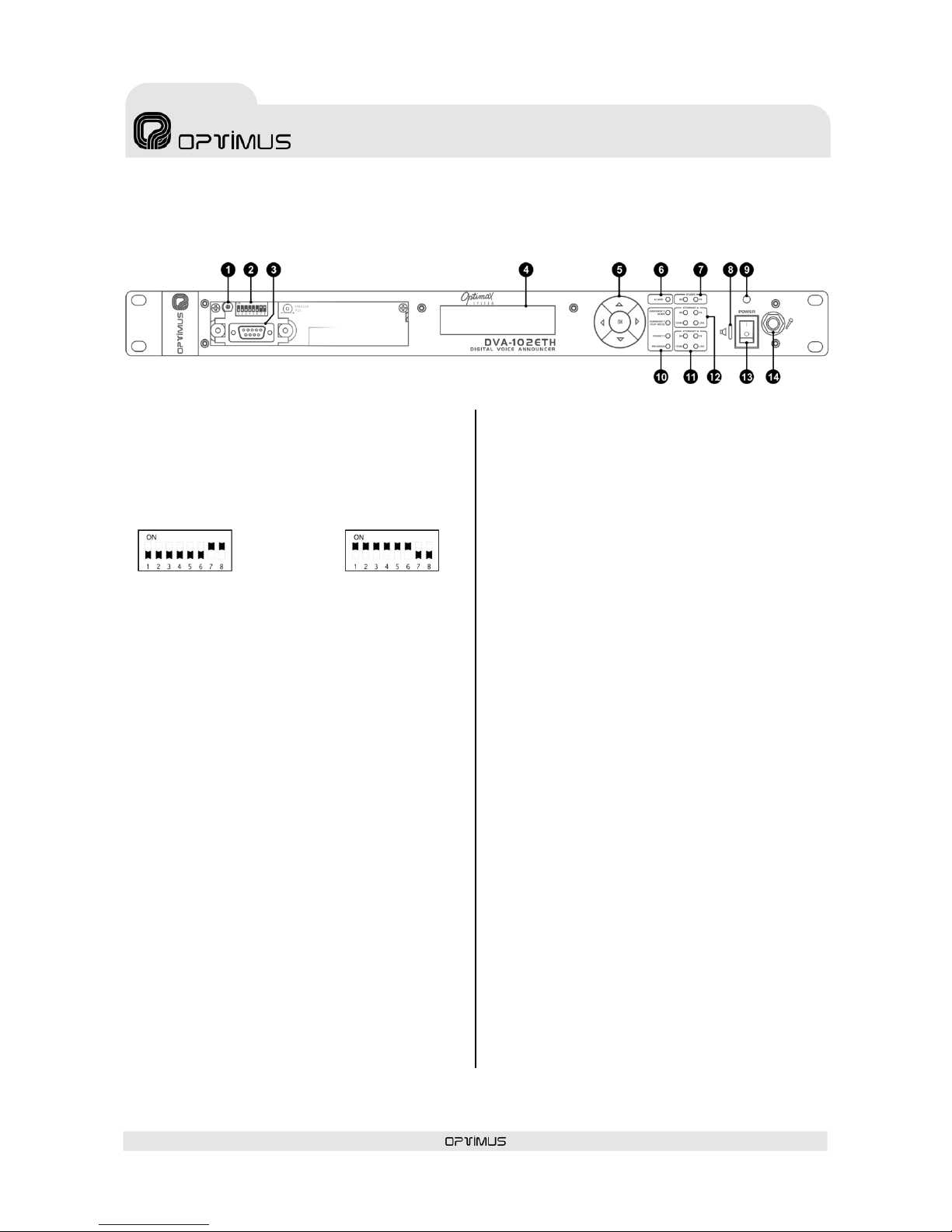
2. FRONT VIEW
(1) Monitor loudspeaker volume adjustment
(2) Download DIP switch
Allows the user to switch between normal working
mode and firmware download mode.
(3) Download connector
Used to update the firmware of the DVA-102ETH.
(4) LCD screen
(5) MENU navigation keys and OK/CANCEL
selection
(6) ALARM indicator
Lights when an alarm is received from the unit itself or
from the system.
(7) RX and TX indicators
Their blinking indicates transmission (TX) or reception
(RX) of data through the RS485 port.
(8) Monitor loudspeaker
This is used to monitor the pre-recorded messages.
(9) Power indicator
Power supply indicator.
(10) Analog function indicators
- Emergency Mode. When lit, it indicates that the
DVA-102ETH has gone into emergency mode.
- Emergency Play Message. Lights when an
emergency message is played.
- Priority. Lights when an emergency message with
priority is played.
- Program. Lights when an emergency message
without priority is played.
(11) Ethernet B input status indicators
- RX. When lit, it indicates that data is being received
through the ETHERNET B input.
- TX. When lit, it indicates that data is being
transmitted through the ETHERNET B input.
- 10 Mb. Indicates the speed of the Ethernet network
connected to the Ethernet B input. If the LED is lit,
it indicates a speed of 10 Mb. If unlit, it indicates a
network speed of 100 Mb (use of a transmission
speed of 100 Mbps is highly recommended).
- LINK. When lit, it indicates the connection of the
Ethernet B input with the HUB or SWITCH.
(12) Ethernet A input status indicators
These serve the same purpose as the ETHERNET B
indicators, applied in this case to the ETHERNET A
input.
(13) Power switch
ON/OFF switch.
(14) Recording input
Used for connection of a microphone to record
messages. The input sensitivity is -60 dBm.
Figure 1
FIRMWARE DOWNLOAD
MODE
NORMAL MODE
Page 7
DVA-102ETH version 1.2 R&D Department 7
DVA-102ETH
Digital voice announcer
and Optimax system gateway
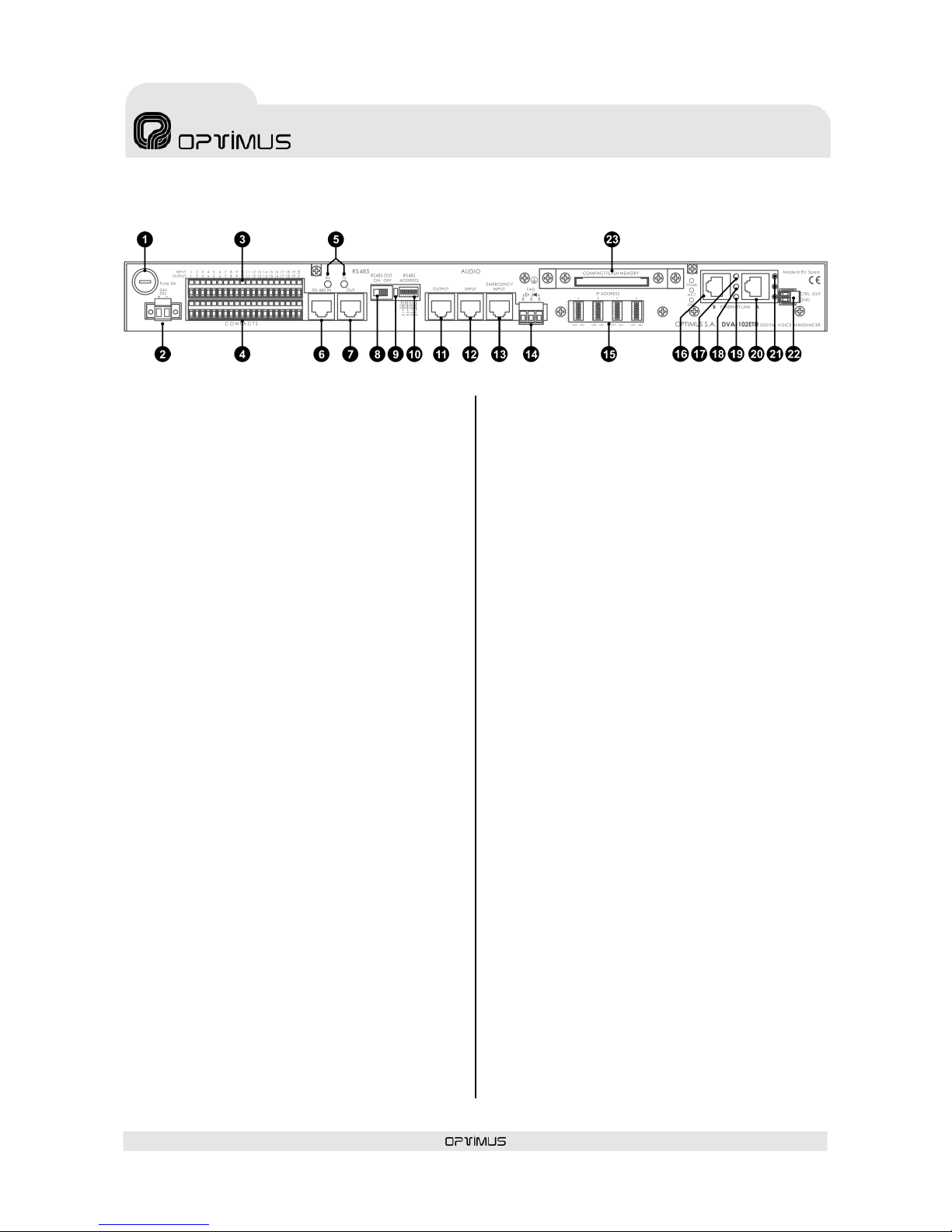
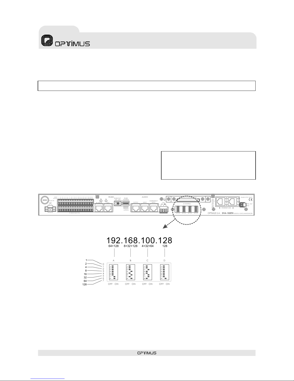
3. REAR VIEW
(1) Power supply fuse
3 A fuse.
(2) Power supply input
To power the DVA-102ETH, connect a power supply of
24 V DC / 2 A to this input.
(3) Input contacts 1 to 19
(4) Output contacts 1 to 19
(5) RX and TX indicators
Their blinking indicates transmission (TX) or reception
(RX) of data through the RS485 port.
(6) RS485 IN connector
RJ45 type connector. This is used to connect the
DVA-102ETH to the RS485 communication bus.
(7) RS485 OUT connector
RJ45 connector. Used to give continuity to the RS485
bus. If this output is used, the RS485 ON/OFF switch
(8) must be moved to the ON position.
(8) RS485 OUT ON/OFF switch
In the ON position, the RS485 output is activated.
(9) Ground to chassis connection
(10) RS485 ADDRESS DIP switch
In mixed or analog installations, the DVA-102ETH
communicates with the various elements of the
SMP-250 system (SU-114N, UMX-02/0, MD-500,
MD500EM...) through an RS485 bus. By means of this
DIP switch a communication address can be assigned to
the unit, inside the RS485 bus. Each unit connected to
an RS485 bus must have a different address. To
configure it, refer to section 4.
(11) AUDIO OUTPUT connector
Balanced analog output of 0 dBm, through the RJ45
connector. To connect it, refer to section 7.4.
(12) AUDIO INPUT connector
Balanced analog input of 0 dBm, through the RJ45
connector. To connect it, refer to section 7.2.
(13) AUDIO EMERGENCY INPUT connector
Analog local input, balanced, with an RJ45 connector
and a sensitivity of 0 dBm, especially suitable for
receiving emergency announcements.
It takes priority over any other signal (ETH inputs,
AUDIO INPUT and pre-recorded messages). To connect
it, refer to section 7.3.
(14) FAIL relay
This is activated when the unit is switched off, when a
failure in the Ethernet connection is detected or an
internal communication error occurs.
(15) IP ADDRESS DIP switches
The IP address of the unit is configured through these 4
DIP switches. This address identifies the DVA-102ETH
in the network, so each unit must have a unique
address.
(16) Ethernet B connector
RJ45 type connector. Used, in a redundant network, as
a secondary connection to the IP network. In
installations with a redundant network, if the
connection to ETH A fails, the unit automatically
switches to this B connection, so that the PA system
continues to operate.
(17) Ethernet B input 10 Mb indicator
Indicates the speed of the Ethernet network connected
to the Ethernet B input. If the LED is lit, it indicates a
speed of 10 Mb. If it is not lit, it indicates a network
speed of 100 Mb.
(18) Ethernet B input ACT indicator
When lit, it indicates that data is being sent or received
through the ETH B input.
(19) Ethernet B input LINK indicator
When lit, it indicates the connection of the ETH B input
with the HUB or SWITCH.
(20) Ethernet A connector
RJ45 type connector. Used for connection to the IP
network.
(21) 10 Mb, ACT and LINK LED indicators of the
Ethernet A input
These serve the same purpose as the ETH B indicators,
applied in this case to the ETH A input.
(22) CTRL OUT strip
Not used.
(23) COMPACT FLASH memory
Figure 2
Page 8
DVA-102ETH version 1.2 R&D Department 8
DVA-102ETH
Digital voice announcer
and Optimax system gateway
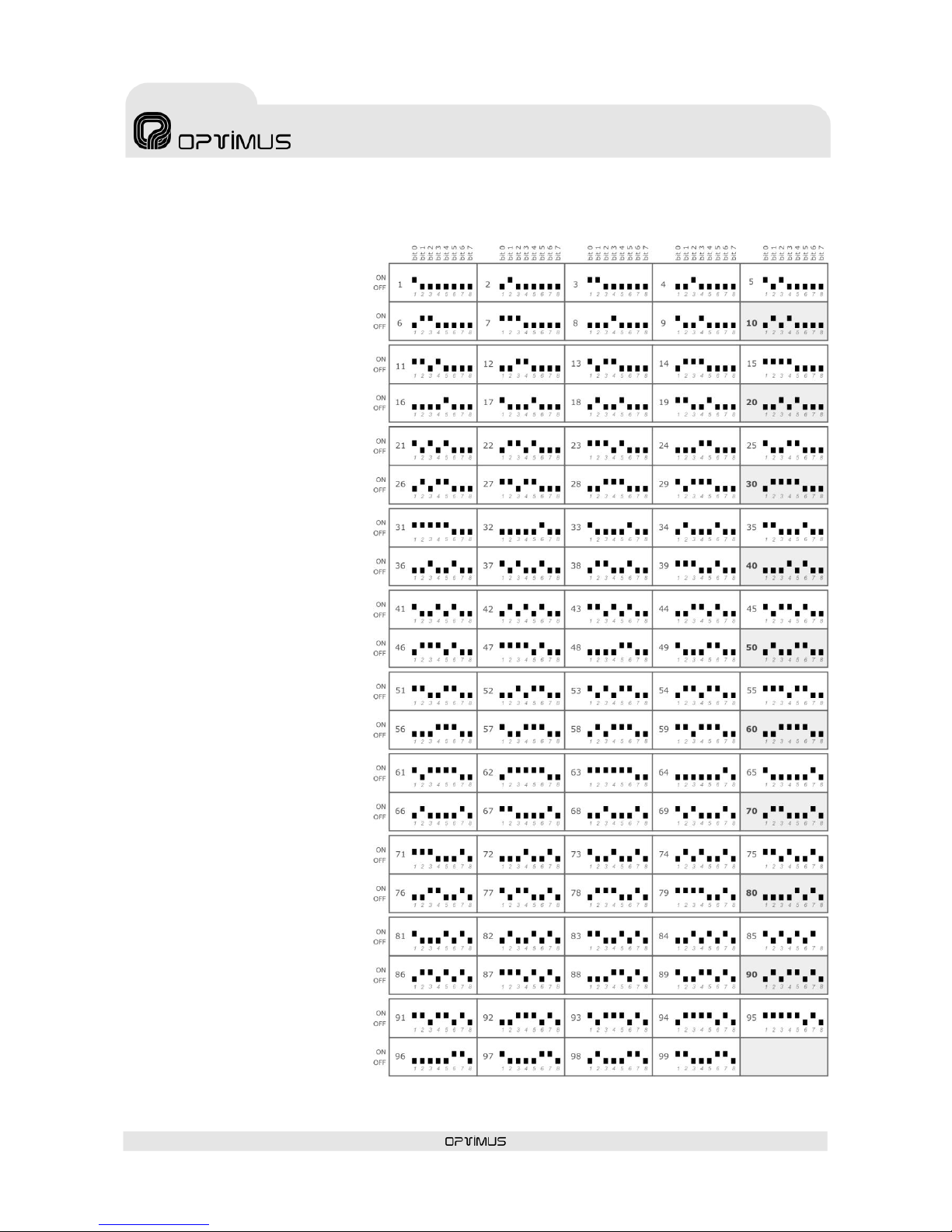
4. CONFIGURATION OF THE RS485 ADDRESS
On an RS485 BUS, each unit must
have a different address. Table I shows
the configuration of the RS485
ADDRESS DIP switches and their
possible values.
Table I
Page 9
DVA-102ETH version 1.2 R&D Department 9
DVA-102ETH
Digital voice announcer
and Optimax system gateway
ATTENTION:
When the unit starts to run, the dipswitches IP address is
automatically saved in the DVA-102ETH flash memory. To
change the address, it is necessary to delete first the IP
address which is saved in the flash memory.
5. CONFIGURATION OF THE IP ADDRESS OF THE UNIT
On the back of the unit there are some DIP switches by means of which the IP address can be configured manually.
This address identifies the unit in the network, so each unit must have a unique IP address.
An IP address is represented by means of a 32-bit binary number. The IP addresses are expressed as decimal notation
numbers: the 32 bits of the address are divided into four octets (an octet is a group of 8 bits). Each octet is
represented by A0 to A7 for the first octet, B0 to B7 for the second octet, C0 to C7 for the third octet and D0 to D7 for
the fourth octet.
Each bit can have the value 0 (DIP switch OFF) or 1 (DIP switch ON). In order to obtain the decimal value of the octet,
the decimal values of each bit that is in the ON position must be added up (from the top down: 1, 2, 4, 8, 16, 32, 64
and 128).
5.1. UNIT IP ADDRESS CONFIGURATION BY MEANS OF DIPSWITCHES
1. Switch off the unit.
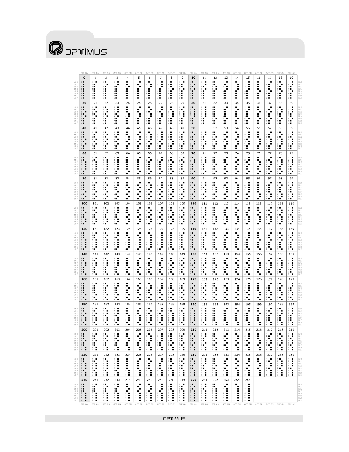
2. Set the required address in the IP Config dipswitches. Table
II on the next page shows all the DIP switch combinations
from 0 to 255.
3. Switch on the unit.
Figure 3 shows an example in which the IP address
192.168.100.128 is configured.
5.2. DELETE THE IP ADDRESS BY MEANS OF DIPSWITCHES
1. Switch off the unit.
2. Set the 0,0,0,0 address in the IP Config dispswitches.
3. Switch on the unit and after 15 seconds, switch it off. The IP address saved in the flash memory has been deleted.
NB: The IP address can also be set by software. To do so, refer to section 5.3.
Figure 3
Page 10
DVA-102ETH version 1.2 R&D Department 10
DVA-102ETH
Digital voice announcer
and Optimax system gateway
TABLE II
Page 11

DVA-102ETH version 1.2 R&D Department 11
DVA-102ETH
Digital voice announcer
and Optimax system gateway
NB: To view the page, it is necessary to deactivate the proxy in the configuration
of the web browser.
ATTENTION
If the IP is activated by software, the functionality of IP
address selection by DIP switches will be deactivated.
Once the change has been made, it can be undone by
deleting the IP software via the web, or by selecting
the address 0.0.0.0 on the DIP switches and restarting
the unit.
ATTENTION:
Once the IP address of the unit has been changed, it is necessary to modify this in the P.A. Manager software as well (see
section 8.1) and to send configurations to the unit (see section 8.6).
5.3. CONFIGURATION OF THE IP OF THE UNIT BY SOFTWARE
(Is necessary configure previously the parameters of the equipment according to paragraph 8)
It is possible to change the IP configuration of the unit by means of the IP ADDRESS DIP switches on the back of the
unit or remotely, without the need for access to the unit, through the P.A. Manager software.
To make the change by software, right click with the mouse on the name of
the DVA-102ETH on the message panel and select the option Web Connection
(1).
If the PC is remote with respect to the installation, open the Internet browser
and enter the IP of the unit in the address bar (for example: http://10.1.1.2).
This IP address is the address configured through the IP ADDRESS DIP
switches situated on the back of the unit.
In both cases, a web page belonging to the unit will load.
Proceed as follows:
1. Enter the password in
the Administrator
Login (2) (contact
technical staff at
Optimus and they will
provide you with this)
and click on Login.
2. Open the Expert menu (3) and click
on the Set IP address option (4).
3. Write the new IP in the IP Address field (5) (for example:
10.1.1.100) and click on Save IP Address (6).
(1)
(2)
(3)
(4)
(5)
(6)
Page 12
DVA-102ETH version 1.2 R&D Department 12
DVA-102ETH
Digital voice announcer
and Optimax system gateway
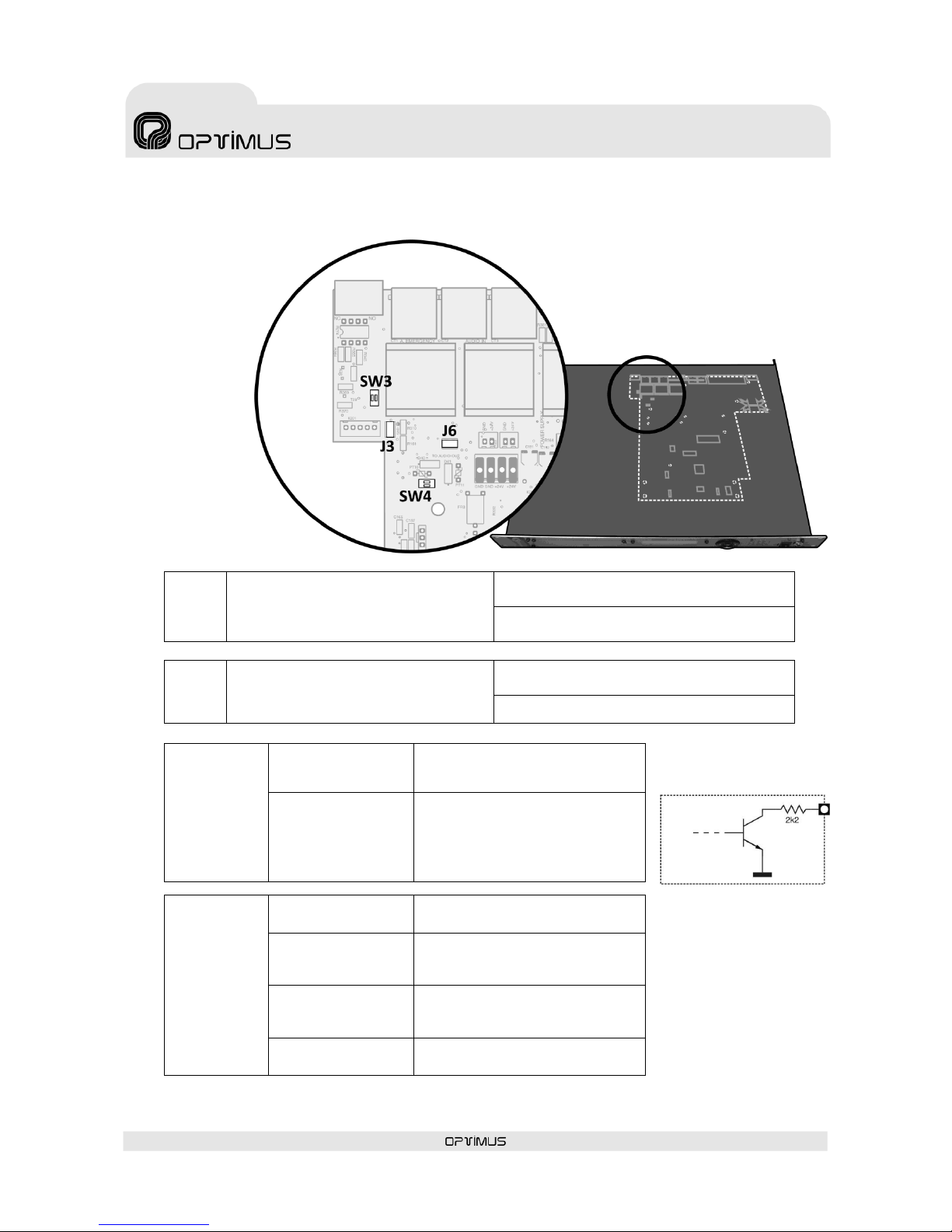
6. INTERNAL CONFIGURATIONS
To gain access to
the DIP switches
and internal
jumpers, it is
necessary to
remove the cover
of the unit. Ensure
that the power
supply to the unit
has been
disconnected
before performing
this operation.
J3
jumper
Separates the shields of the EMERGENCY
INPUT, AUDIO INPUT and AUDIO OUTPUT
connectors from the ground connection of
the signal circuit.
J3 positioned: Shields grounded
(factory configuration)
J3 not positioned: Shields and ground
connection separated
J6
jumper
Connects the live voice priority contact of
the EMERGENCY INPUT connector to the
output priority contact of the AUDIO
OUTPUT connector.
J6 positioned: Priorities connected
(factory configuration)
J6 not positioned: Priorities independent
Dipswitch
SW3
DIPSWITCH 1= ON
DIPSWITCH 2= OFF
GND on PIN 8 of the EMERGENCY
INPUT connector (factory
configuration
DIPSWITCH 1= OFF
DIPSWITCH 2= ON
ALARM indicator contact on PIN 8 of
the EMERGENCY INPUT connector.
This contact is an open collector
output, in accordance with the
figure 4b below.
Dipswitch
SW4
DIPSWITCH 1= ON
PHANTOM power supply of the
AUDIO INPUT ENABLED
DIPSWITCH 1= OFF
PHANTOM power supply of the
AUDIO INPUT DISABLED
(factory configuration)
DIPSWITCH 2= ON
PHANTOM power supply of the
EMERGENCY INPUT ENABLED
(factory configuration)
DIPSWITCH 2= OFF
PHANTOM power supply of the
EMERGENCY INPUT DISABLED
Figure 4
Figure 4b
Page 13
DVA-102ETH version 1.2 R&D Department 13
DVA-102ETH
Digital voice announcer
and Optimax system gateway
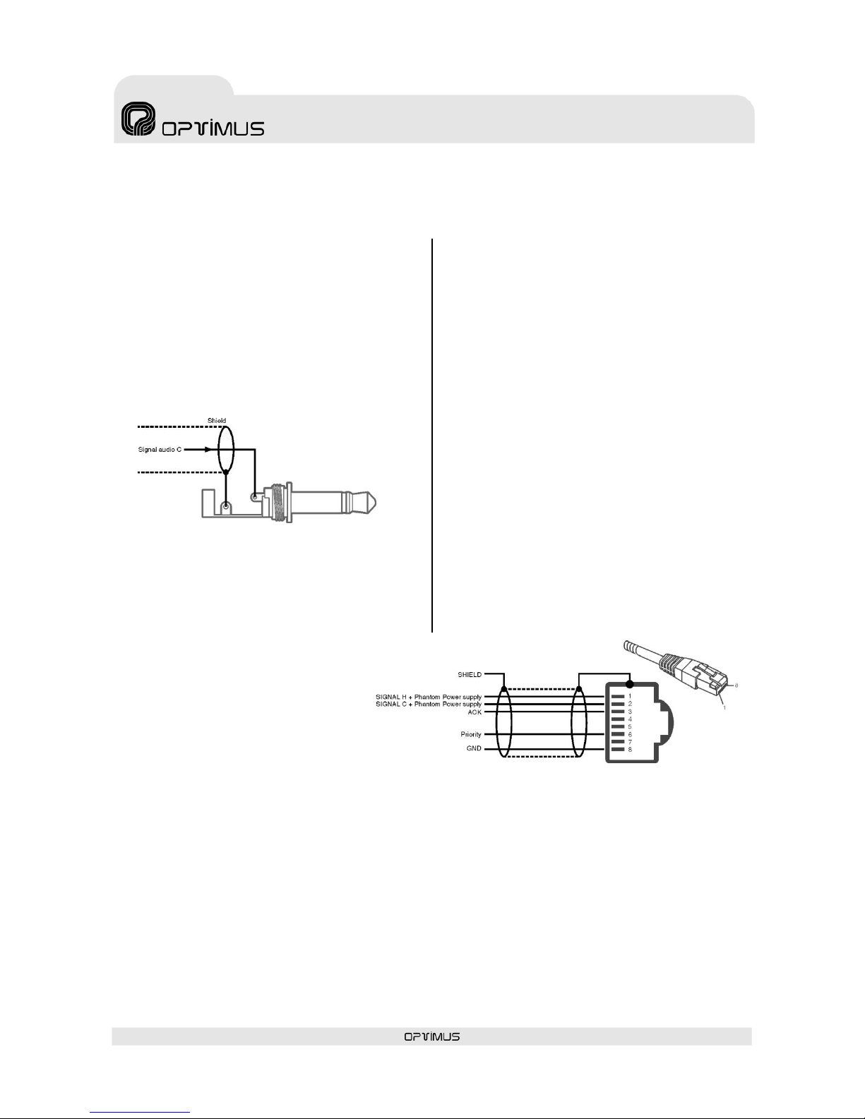
Figure 5
Figure 6
7. EQUIPMENT CONNECTIONS
7.1. RECORDING MICROPHONE
CONNECTION
The unit has a mono female JACK input of 6.35 mm on
the front to connect a microphone for recording
messages. The input sensitivity is -60 dBm.
For its connection, refer to Figure 5.
7.2. AUDIO INPUT CONNECTION
Analog local input, balanced, with an RJ45 connector
and a sensitivity of 0 dBm.
For its connection, refer to Figure 6.
Pin 1: Audio H (Hot).
Pin 2: Audio C (Cold).
Through contacts 1 and 2, this input can provide a
“PHANTOM”-type power supply of 24 V DC. See section
6. INTERNAL CONFIGURATIONS.
Pin 3: Acknowledge. This output contact allows
synchronisation with external desks (MD-94 family),
avoiding initial signal loss from the desk due to possible
delays in activation.
Pin 6: Priority input contact.
Pin 8: GND
When the internal jumper JP3 is removed (see section
0), the shield of the Cat 5 FTP cable is separated from
the ground connection of the signal circuit. In certain
installations, this makes it possible to eliminate
alternating noises caused by ground loops.
Page 14
DVA-102ETH version 1.2 R&D Department 14
DVA-102ETH
Digital voice announcer
and Optimax system gateway
Figure 8
Figure 7
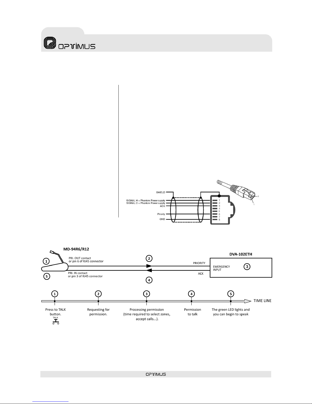
7.3. EMERGENCY INPUT CONNECTION
Analog local input, balanced, with an
RJ45 connector and a sensitivity of 0
dBm, especially suitable for
emergency announcements.
This input has priority over any
other signal from the unit.
The emergency announcements are
activated when pin number 6
(speech preference) is connected to
pin number 8 (GND) of the
connector.
Although the DVA-102ETH may not
be powered, the signal applied to
this input appears in the AUDIO
OUTPUT when speech preference is
activated.
For its connection, refer to Figure 7.
Pin 1: Audio H (Hot).
Pin 2: Audio C (Cold).
Through contacts 1 and 2, this input provides a “PHANTOM”-type power
supply of 24 V DC (see section 6) to power the emergency desk.
Pin 3: Acknowledge. Allows synchronisation with external desks (MD-94
family), avoiding initial signal loss from the desk due to possible delays in
activation. Figure 8 shows an example of ACK operation between micro
MD-94 and DVA-102ETH.
Pin 6: Priority contact of the live voice emergency message.
It is connected to pin 6 of the AUDIO OUTPUT (priority output) connector
through the internal jumper J6 (see section 0).
Pin 8: GND.
By changing the configuration of some internal DIP switches (see section
6), this contact becomes an open collector output which is activated
whenever the system detects an alarm.
Page 15

DVA-102ETH version 1.2 R&D Department 15
DVA-102ETH
Digital voice announcer
and Optimax system gateway
7.4. AUDIO OUTPUT CONNECTION
Balanced analog output, with an RJ45 connector and a sensitivity of 0 dBm.
For its connection, refer to Figure 9.
Pin 1: Audio H (Hot).
Pin 2: Audio C (Cold).
Pin 3: 24 V DC input. Provides the EMERGENCY INPUT
with a phantom power supply, even when the DVA102ETH is not powered.
Pin 6: Output priority contact. It is activated:
when a Compact Flash message from the DVA-
102ETH is played,
when the priority contact of the AUDIO INPUT is activated,
when priority digital audio is received through the ETH A or B inputs,
when an input contact configured as Local message activation is activated.
Pin 8: GND.
7.5. INPUT CONTACTS
CONNECTION
The unit has 19 input contacts, which can be
configured by means of the P.A. Manager
software.
To activate a contact, this contact must be
grounded.
These inputs are used for:
Local pre-recorded message activation:
When the input contact is activated, a prerecorded message is sent from the DVA102ETH to one or several zones.
Zone selection: When the input contact is
activated, a destination zone is preselected. When the priority of the AUDIO
INPUT is activated, the signal applied to the
AUDIO INPUT will be sent to this zone.
7.6. OUTPUT CONTACTS CONNECTION
The unit has 19 output contacts, which can be configured by means of the P.A.
Manager software.
They are open collector outputs, as shown in the diagram in Figure 11. These
outputs can be used, for example, to activate analog zones, to select zones of an
MC12/24L, to activate the priority of external devices, to light a LED…
Figure 11
Figure 9
Figure 10. Example of input contacts connection for activation of pre-
recorded messages from the DVA-102ETH.
Figure 11
Page 16

DVA-102ETH version 1.2 R&D Department 16
DVA-102ETH
Digital voice announcer
and Optimax system gateway
7.7. RS485 BUS CONNECTION
One of the DVA-102ETH functions is that it can act as a link between an installation in an OPTIMAX network and
analog PA systems with UMX-02/0 or UDCE-01 zones and analog power units.
For this purpose, the DVA-102ETH must communicate with the various elements of the analog system (UMX-02/0,
MD-500, MD-500EM, UDCE-01…) through an RS485 bus.
This communication allows to:
Translate the zone selection commands received via Ethernet into RS485 commands (by Polling in installations
with UDCE-01 zones and by CSMA in installations with UMX-02 zones).
Receive system alarms via RS485, display them on the front LCD screen and communicate them to other units
with an ETHERNET connection (DC-600ETH, FC-600ETH…).
RJ45 connectors with a metal housing are used for the RS485 connection.
If the unit is positioned as the first or last element of the RS485 bus, the RS485 OUT switch must be moved to the OFF
position. Otherwise, the RS485 output must be enabled by moving the switch to the ON position.
Use category 5 FTP cable to connect different units to each other on the same RS485 bus.
Figure 12
Page 17

DVA-102ETH version 1.2 R&D Department 17
DVA-102ETH
Digital voice announcer
and Optimax system gateway
8. CONFIGURATION BY SOFTWARE
For the unit implementation in the installation, it is necessary to have a PC connected to the DVA-102ETH, either
through the ETHERNET network, or through a crossed network cable.
The PC must have the P.A. Manager software installed.
1. Open the P.A. Manager software and on the installation screen add the DVA-102ETH to the installation structure.
The DVA-102ETH must be associated with a PA Area.
2. Configure the configuration parameters of the unit. They are divided into three sections, accessed via tabs:
General: The general communication parameters, such as IP, RS485 addresses, etc., can be configured here
(see section 8.1).
Parameters: This is where the language of the menus, the passwords and the digital audio volume can be
configured (see section ¡Error! No se encuentra el origen de la referencia.).
Contacts: The functions of the input and output contacts of the DVA-102ETH can be configured here (see
section 8.3).
3. Connect the equipment to the installation structure (see section 8.4).
4. The DVA-102ETH must be associated with the Server PC (see section 8.5).
5. Send the configurations to the unit (see section 8.6).
8.1. GENERAL CONFIGURATION
(1) Name
Enter a name to identify
the unit (maximum of 20
characters).
RS485 PARAMETERS
(2) Address
Every equipment unit
connected to an RS485
bus must have a unique
address which
distinguishes it from the
other units connected to
the same bus. Enter a
value of between 1 and
99. The address entered
must coincide with the
address configured
through the RS485
ADDRESS DIP switch on
the rear panel of the DVA102ETH.
(3) RS485 Polling Freq.
Frequency with which the
DVA-102ETH
communicates with each
unit in the installation (DALA-01/0B, UMX-02/0,
MD500, MD500EM...) in order to receive information
about the status of each of these units (incidents). The
incidents are displayed on the screen of the unit.
Values: Between 1 and 60 seconds.
It is recommended to have the highest possible polling
frequency, in accordance with the characteristics of
each installation.
Default value: 10 seconds.
Figure 13
(1)
(3)
(4)
(6)
(5)
(7)
(11)
(12)
(14)
(15)
(16)
(17)
(8)
(9)
(13)
(10)
(2)
Page 18

DVA-102ETH version 1.2 R&D Department 18
DVA-102ETH
Digital voice announcer
and Optimax system gateway
POLLING
CSMA
DVA-102ETH
•
•
DALA-01/0B
•
•
MD-500EM
•
SU-114N •
SU-214/0N
• UMX-02/0
• ECM-01 •
UDCE-01 •
(4) CSMA/POLLING
The DVA-102ETH can use two different types of RS485
protocol: POLLING or CSMA (Carrier Sense Multiple
Access).
Select the type of
protocol according
to the units
connected to the
RS485 bus, taking
account of the table
attached.
It must be
remembered that
units which use
different protocols
cannot be
connected on the
same RS485 bus.
IP DATA
(5) IP Address
Enter the IP address of the unit. This IP must be unique
in the installation and it must coincide with the
configuration of the DIP switches on the back of the
unit, or with the address configured through the Web
connection (see section ¡Error! No se encuentra el
origen de la referencia..1). It must be a fixed IP
address.
(6) Netmask (7) Gateway
In installations that require it. Consult the network
administrator of the installation.
MULTICAST DATA (also see pages 17 and 18)
(8) IP Multicast
Default setting 239.5.5.5. Do not modify this field
unless the installation topology makes it necessary. All
the units with an IP connection in the installation must
have the same IP multicast address.
(9) Multicast Port
Default setting 5000. Do not modify this field unless the
installation topology makes it necessary. All the units
with an IP connection in the installation must have the
same multicast port.
(10) Send “Heart beat” every n seconds.
Frequency with which the unit sends a heart beat signal
to the multicast group. This signal informs the other
units with an Ethernet connection in the installation
that the DVA-102ETH is operating perfectly.
(11) Local Manager and (12) Global Manager
Only on Optimax systems. Defines whether the
DVA-102ETH is to function as a priority manager of the
Optimax system, either locally at PA Area level or
globally for the installation, and establishes the priority
of this management with respect to other equipment
units (1 = maximum priority). It is not advisable to
activate this management on the DVA-102ETH (see
Notes on Local and Global Co-ordinators on page 19).
(13) RS485 Gateway
Enable this function in installations in which the DVA102ETH is connected to another equipment unit by
means of the RS485 bus.
If there is more than one DVA-102ETH connected to the
RS485 bus, only one of them will have the RS485 Gateway
function activated.
(14) Associated Audio Input
Used on DVA-102ETH units whose AUDIO OUT output is
connected to an UMX-02/0 input card. Open the dropdown menu and select this input. Beforehand, it is
necessary to configure the UMX-2E cards of the
UMX-02/0.
(15) Emergency source
Defines the priority level of the EMERGENCY INPUT of
the DVA-102ETH with respect to the other audio signals
in the installation.
When the DVA-102ETH is added to the installation, the
Emergency DVA sound source is automatically created,
and this source is associated with the EMERGENCY Mode;
in this way, the priority of this input with respect to the
other signals in the installation is established.
This default configuration can be modified through the
menu Optimax > Modes and Sound Sources.
(16) Priority source
Defines the priority level of the AUDIO INPUT of the
DVA-102ETH with respect to the other audio signals in
the installation, when this input receives a priority
signal (when the priority contact of the AUDIO INPUT is
activated).
When the DVA-102ETH is added to the installation, the
Priority DVA sound source is automatically created, and
this source is associated with the PRIORITY Mode; in this
way, the priority of this input with respect to the other
signals in the installation is established.
This default configuration can be modified through the
menu Optimax > Modes and Sound Sources.
(17) Program source
Defines the priority level of the AUDIO INPUT of the
DVA-102ETH with respect to the other audio signals in
the installation, when this input receives a program
signal (when the priority contact of the AUDIO INPUT is
not activated).
When the DVA-102ETH is added to the installation, the
Music DVA sound source is automatically created, and
this source is associated with the Music Mode; in this
way, the priority of this input with respect to the other
signals in the installation is established.
This default configuration can be modified through the
menu Optimax > Modes and Sound Sources.
Page 19

DVA-102ETH version 1.2 R&D Department 19
DVA-102ETH
Digital voice announcer
and Optimax system gateway
a) Information about the multicast configuration in Optimax equipment
It is possible to modify the multicast configuration of all the equipment units in the installation simultaneously. Proceed as follows:
1. From the installation screen, open
the Options menu and select
Multicast Configuration.
2. A window with the configurations
of the multicast group appears.
Double click on the data item
that you wish to change.
3. Modify the value and click on
Accept.
4. Confirm the change by clicking on
Yes.
5. Close the multicast configuration window by clicking on OK.
ATTENTION: The values that are modified from the multicast configuration window affect all the equipment units in the
multicast group in the installation.
Page 20

DVA-102ETH version 1.2 R&D Department 20
DVA-102ETH
Digital voice announcer
and Optimax system gateway
Default base Multicast addresses, ports and configurations
Broadcast address
Broadcast port
Initial configuration download
255.255.255.255
3333
Multicast address
Multicast port
Initial configuration download
239.5.5.5
8001
Multicast address
Multicast port
Others
Control data
239.5.5.5
5000
Heart beat every 10 seconds
Global audio channels
239.1.0.x
6000 + x
8 simultaneous channels
Local audio channels
239.1.PAArea.x
6000 + (PAArea*100) + x
5 simultaneous channels
Valid ranges (according to the IANA Guidelines for IPv4 Multicast Address)
Multicast address
Multicast port
Others
Control data
Between 239.0.0.0 and
239.255.255.255
Between 1025 and 65536
Heart beat between 1 and 65000
seconds.
Global audio channels
Between 239.0.0.0 and
239.255.255.255
Between 1025 and 65536
1-50 simultaneous channels
Local audio channels
Between 239.0.0.0 and
239.255.255.255
Between 1025 and 65536
1-50 simultaneous channels
b) Notes on Local and Global Co-ordinators
The system requires management of the digital audio channels at all times, so that the data may circulate freely across the network.
This function is performed by two applications: one at a local level, known as LCC, which manages the digital channels at PA Area
level, and another, known as GCC, which manages the digital channels at a global level (between different PA areas and/or servers).
Each PA Area needs at least one LCC process on one of its equipment units.
If there is more than one PA Area in an installation, and announcements have to made or music programs have to be sent between
PA Areas, a minimum of one GCC process is required on an equipment unit in the installation.
If the number of equipment units so permits, it is advisable to have each process available on at least two equipment units. In this
way, the applications continue to work even when a fault in one of the equipment units occurs.
There are specific equipment to run these applications: CC-100ETH, UMX-CC and UMX-ETH (Control). It is recommended that they
are the ones who made the role of coordinator. If these equipment are not present in the installation, it is advisable that the COU02/0ETH, performs the functions of co-ordinator.
The recommended order of priority depending on the model is as follows:
CC-100ETH
UMX-CC
UMX-ETH
(Control)
COU-02/0ETH
SU-114N
SU-214/0N
UP-xETH
(Backup amplifier)
UP-xETH
UMX-ETH
(program
or priority)
DVA-102ETH
DC-600ETH
FC-600ETH
>
> > >
>
Page 21

DVA-102ETH version 1.2 R&D Department 21
DVA-102ETH
Digital voice announcer
and Optimax system gateway
8.2. CONFIGURATION OF PARAMETERS
Click on the Parameters tab to view the configuration options.
(1) Language
Configures the language in which the
messages appear on the LCD screen
of the DVA-102ETH.
(2) Buzzer (NOT IMPLEMENTED)
The DVA-102ETH has a buzzer which
is activated when an alarm is
received. This control activates or
deactivates the buzzer.
(3) Keypad Sound (NOT
IMPLEMENTED)
Activates or deactivates the sound of
the keys (PLAY, REP, TALK and
GONG+TALK make no sound).
(4) Administrator Control and (5)
Operator Control
(NOT IMPLEMENTED)
In order to restrict access to certain
functions of the DVA-102ETH from the
controls on the front, 3 user levels
have been established: Basic, Operator and
Administrator.
Through these parameters, the Administrator password
and the Operator password can be established.
Basic
Default level when the unit is switched on. Without
password. Allows basic operations such as sending
pre-recorded messages and viewing the status of
the volume.
Operator
With password (by default 1234). In addition to all
the operations available to the basic user, the zone
volume can be modified.
Administrator
With password (by default 1234). Without any
restriction.
COMPACT FLASH MESSAGES
Volume controls for the pre-recorded messages
resident in the Compact Flash memory of the DVA102ETH.
(6) Volume, Treble and Bass controls of the
messages configured as Program in the Compact Flash
memory. Only for OGG format messages.
(7) Volume, Treble and Bass controls of the
messages in the Compact Flash memory of the DVA102ETH. Only for OGG format messages.
(8) Recording Volume
This adjusts the input volume of the recording micro on
the front of the DVA-102ETH.
DIGITAL AUDIO MESSAGES
(9) Digital Audio Messages. Program Volume,
Treble and Bass Controls
Establishes the volume, treble and bass levels of the
program digital audio signal received by the DVA102ETH.
(10) Digital Audio Messages. Priority Volume,
Treble and Bass Controls
Establishes the volume, treble and bass levels of the
priority digital audio signal received by the DVA102ETH.
Figure 14
(1)
(9)
(6)
(4)
(3)
(10)
(8)
(7)
(2)
(5)
Page 22

DVA-102ETH version 1.2 R&D Department 22
DVA-102ETH
Digital voice announcer
and Optimax system gateway
8.3. CONFIGURATION OF CONTACTS
The DVA-102ETH has two rear strips:
an input contacts strip and an output
contacts strip. Each contact that it is
wished to use must be individually
configured by clicking on the Contacts
tab.
(1) New
Creates a configuration of a contact
that is yet to be used.
(2) Edit
Allows to modify the configuration of a
contact.
(3) Delete
Deletes the configuration of a contact.
(4) Number
Contact number that has to be
configured.
(5) Name
Enter a name to identify the contact.
(6) In/Out
Defines whether the contact that is being configured
belongs to an input (upper strip of the DVA-102ETH) or
to an output (lower strip).
(7) Standby Status
Select the status of the contact when it is on standby.
NO: Normally open.
NC: Normally closed.
(8) Function
Defines the function of the contact. The functionalities
available vary depending on whether the contact has
been defined as input or output.
Functionalities of the contact defined as Input:
Disabled: Nothing occurs when the input contact is
activated.
Local Message Activation: When the input
contact is activated, a pre-recorded message is
sent from the DVA-102ETH to one or several zones.
The message and the zones are configured by
means of the Message and Zones drop-down
menus that appear when this functionality is
selected. Also configure the Activation Mode,
choosing between Pulse and Level. If pulse is
configured, a pulse is required to activate the
message and another pulse is required to stop it.
The duration of the pulse must be at least 500
milliseconds.
Zone selection: When the input contact is
activated, a destination zone is pre-selected. This
zone is defined in the Zone drop-down menu that
appears when this functionality is selected. When
the priority of the AUDIO INPUT is activated, the
signal from the AUDIO INPUT will be sent to this
zone.
Functionalities of the contact defined as Output:
Disabled: The output contact is not used.
Analog Zone Activation: One or several output
contacts are assigned to an analog zone (the
analog zones must be created beforehand, see
section 8.3.1). The contacts assigned will be
activated whenever a (live voice or pre-recorded)
message is sent from a unit in the installation to
this analog zone.
The zone is defined in the Zone drop-down menu
that appears when this functionality is selected.
Once the parameters accessed via the three tabs of the DVA-102ETH (General – Parameters - Contacts) have been
configured, click on the button Accept in the lower part of the window.
Figure 15
(2)
(1)
(3)
(4)
(6)
(8)
(5)
(7)
Page 23

DVA-102ETH version 1.2 R&D Department 23
DVA-102ETH
Digital voice announcer
and Optimax system gateway
8.3.1. CREATION OF DVA-102ETH ANALOG ZONES
On the DVA-102ETH, an analog zone is an analog amplifier that
receives audio from the AUDIO OUTPUT and whose priority is
activated by an output contact of the DVA-102ETH.
To create analog zones, proceed as follows from the P.A. Manager
installation screen:
1. Select the DVA-102ETH to which you wish to add analog
zones.
2. Open the Add Equipment menu and select Analog Zone.
3. Enter a name to identify the zone.
4. Enter a zone number.
5. Click on the output contacts that you wish to associate with
this zone (the contacts assigned are shown in green). These
contacts will be activated whenever a (live voice or prerecorded) message is sent from a unit in the installation to
this analog zone.
The contacts that appear in grey are output contacts already
used by another analog zone.
8.4. CONNECTING THE EQUIPMENT IN THE INSTALLATION
STRUCTURE
When equipment units are added to the installation, they appear in the structure with their name in red, preceded by
the “disconnection” icon. While their status is shown as disconnected, these units are not operative.
To connect the equipment, proceed as follows:
1. In the installation structure, right click with the mouse on the
disconnected equipment unit.
2. Click on Connect Equipment. The connection icon appears and the name
of the equipment unit is shown in green.
Figure 16
= Equipment disconnected
= Equipment connected
Page 24

DVA-102ETH version 1.2 R&D Department 24
DVA-102ETH
Digital voice announcer
and Optimax system gateway
8.5. ASSIGNING THE DVA-102ETH TO A SERVER PC
In installations with a Server PC, in order to be able to send DVA-102ETH messages from the P.A.
Manager, it is necessary to associate the DVA-102ETH with the Server PC.
1. On the installation tree, right
click with the mouse on the
Server PC and select the option
Edit Equipment.
2. In the Server PC configuration
window, click on the Associated
DVA-102ETH tab (1).
3. Select the DVA from the list
headed Available DVA-102ETH (2)
and click on the button Add (3).
The DVA selected appears in the
Selected DVA-102ETH window (4).
4. Click on OK (5).
8.6. SENDING CONFIGURATIONS TO THE
UNIT
1. Open the File menu and click on Save.
2. On the installation tree, right click with the mouse on the DVA-102ETH that
has just been configured and select the option Send Configurations.
3. A progress bar appears. Upon completion, click on OK.
You can exit the installation screen by opening the File menu and selecting Exit.
The P.A. Manager software will restart automatically.
8.7. EDITING THE CONFIGURED PARAMETERS
If required, the configurations of the DVA-102ETH can be edited. Proceed as
follows:
1. Open the installation screen of the P.A. Manager software.
2. In the installation structure, right click with the mouse on the name of the
DVA-102ETH whose configuration you wish to edit.
3. Select Edit Equipment.
4. The configuration window appears. Edit the parameters as required.
5. Once the parameters have been configured, click on the button OK.
6. Save the configuration by opening the File menu and selecting Save.
7. Send the configurations to the unit (Section 8.6).
(2)
(3)
(4)
(5)
(1)
Page 25

DVA-102ETH version 1.2 R&D Department 25
DVA-102ETH
Digital voice announcer
and Optimax system gateway
(3)
(2)
(1)
(4)
9. PRE-RECORDED MESSAGES
The digital messages are stored on the 2 GB Compact Flash memory card, which is supplied together
with the DVA-102ETH.
9.1. CHARACTERISTICS
Access/Updating of messages
By means of the Server PC and the P.A. Manager software through the
Ethernet connection.
By means of a Compact Flash card reader connected to a PC.
Memory capacity:
2 GB
File format admitted
OGG, WAV
9.2. TRANSFER OF MESSAGES TO THE DVA-102ETH MEMORY
There are two different ways of recording files in the Compact Flash memory of the DVA-102ETH.
A. Recording onto the memory by means of a Compact Flash card reader.
1. Remove the memory from the DVA-102ETH and position it in a Compact Flash memory card reader connected to
the PC that contains the files.
2. Use the PC browser to copy the files from the computer to the memory, which will be shown as an additional disk
unit.
3. Put the memory back into the DVA-102ETH.
B. Recording onto the memory inserted in the DVA-102ETH itself.
1. Open the P.A. Manager
program from the
Server PC.
2. Open the Messages
menu and select Pre-
recorded Messages
Management (DVA).
3. Select the Local
Messages tab (1) if you
wish to copy messages
to just one DVA102ETH. Select its
name from the dropdown menu (3).
4. Select the Common
Messages tab (2) if you
wish to copy the
messages to all the
DVA-102ETH units in
the installation.
5. Click on the button Add
New Files (4).
Figure 18
Page 26

DVA-102ETH version 1.2 R&D Department 26
DVA-102ETH
Digital voice announcer
and Optimax system gateway
(3)
(4)
(1)
(5)
(6)
(2)
6. Locate the files that you wish to copy and select
them (to select more than one, hold the Ctrl. key
down).
7. Click on the button Open (5).
The messages selected are added to the list and
copied to the Compact Flash card of the
DVA-102ETH.
9.3. ASSIGNMENT OF PRIORITY LEVELS TO MESSAGES
1. Open the P.A. Manager program from the Server PC.
2. From the operator screen, open the Messages menu and select Pre-recorded Message Management (DVA). It is also
possible to perform this operation from the Installation screen by selecting the menu Options > Pre-recorded Message
Management (DVA).
3. Locate the message whose parameters you wish to change.
If it is a local message, click on the Local Messages tab (1), select the name of the DVA-102ETH (2) from the dropdown menu and then select the message. To make a multiple selection, hold the Ctrl. key down.
If the message is one of the Common Messages, click on the Common Messages tab (3) and select the message. In
this case, the parameters of this message will be changed on all the DVA-102ETH units in the installation.
4. Activate the option Change settings (4).
5. Open the drop-down
menu Mode (5) and
select a priority level.
These priority levels or
modes are
automatically created
when the DVA-102ETH
is added to the
installation. If required,
the modes can be
modified through the
menu Optimax > Modes
and Sound Sources.
6. Finally, click on Apply
changes (6).
(5)
Figure 19
Figure 20
Page 27

DVA-102ETH version 1.2 R&D Department 27
DVA-102ETH
Digital voice announcer
and Optimax system gateway
Moves the user to
the higher level
menu.
Enters the menu shown
on the screen
Moves the user to the next
menu on the same level
Moves the user to the
previous menu on the same
level
Starts or activates the
menu option selected
10. OPERATIONS FROM THE FRONT CONTROLS
Through the front controls and the LCD
screen, it is possible to perform some basic
operations:
Monitor messages of the DVA-102ETH
Modify program and priority volumes of
the DVA-102ETH
Record DVA-102ETH messages
View system alarms.
Use the navigation keys to view and select
the various menu options.
10.1. MENU STRUCTURE
Page 28

DVA-102ETH version 1.2 R&D Department 28
DVA-102ETH
Digital voice announcer
and Optimax system gateway
10.2. OPERATIONS FROM THE DVA-102ETH MENU
10.2.1. CHANGE THE MENU LANGUAGE
1. From the start screen, press .
2. Press until you see the CONFIGURATIONS
menu on the screen.
3. Press to enter the CONFIGURATIONS menu.
4. Press until you see the option DVA language
selection on the screen.
5. Press and select the required language by means
of the and keys.
6. Press OK.
10.2.2. MONITOR A MESSAGE
1. From the start screen, press .
2. From the PLAYER menu, press .
3. Select the message that you wish to monitor by
means of the and keys.
4. Press OK.
NB: The message monitored is only played through the
monitor loudspeaker of the DVA-102ETH. It is not sent
to any zone in the installation.
10.2.3. STOP MONITORING / PLAYING
OF A MESSAGE
This process is valid for:
- Stopping a message in progress which has been
activated from a server PC or through an input
contact.
- Stopping a message that is being monitored.
1. When a message is being played or monitored, it
appears on the screen. Press .
2. Press until you see the option STOP ACTIVE
CHANNEL on the screen.
3. Press OK.
10.2.4. RECORD A MESSAGE FROM THE
DVA-102ETH
1. Connect a microphone to the front recording input
of the DVA-102ETH.
2. From the start screen, press .
3. Press until you see the option ACQUISITION
MICROPHONE on the screen.
4. Press to enter the menu.
5. Press OK to start recording.
6. Press OK to stop recording.
7. Press OK (option OK) to save the selection or
press to select Cancel and eliminate it.
The maximum recording time is 30 seconds. After this
time, recording stops automatically.
10.2.5. VIEW THE SYSTEM ALARMS
1. From the start screen, press .
2. Press until you see the option ALARM LIST on
the screen.
3. Press to enter the menu.
4. View the alarms by means of the and keys.
10.2.6. MODIFY THE ETH PROGRAM
VOLUME
Establishes the volume, treble and bass levels of the
program digital audio signal received by the DVA102ETH via IP.
1. From the start screen, press .
2. Press until you see the option
CONFIGURATIONS on the screen.
3. Press to enter the CONFIGURATIONS menu.
The option Modify ETH PROGRAM volumes
appears.
4. Press to view the program volumes.
5. Select the volume that you wish to modify by
means of the and keys.
6. Situate the volume in the desired position by
means of the and keys.
7. Press OK.
Page 29

DVA-102ETH version 1.2 R&D Department 29
DVA-102ETH
Digital voice announcer
and Optimax system gateway
10.2.7. MODIFY THE ETH PRIORITY
VOLUME
Establishes the volume, treble and bass levels of the
priority digital audio signal received by the DVA102ETH via IP.
1. From the start screen, press .
2. Press until you see the option
CONFIGURATIONS on the screen.
3. Press to enter the CONFIGURATIONS menu.
4. Press until you see the option Modify ETH
PRIORITY volumes on the screen.
5. Press to view the priority volumes.
6. Select the volume that you wish to modify by
means of the and keys.
7. Situate the volume in the desired position by means
of the and keys.
8. Press OK.
10.2.8. MODIFY THE CF (COMPACT
FLASH) PROGRAM VOLUME
(NOT IMPLEMENTED) Establishes the volume, treble
and bass levels of the messages configured as program
in the Compact Flash memory of the DVA-102ETH.
10.2.9. MODIFY THE CF (COMPACT
FLASH) PRIORITY VOLUME
Establishes the volume, treble and bass levels of the
messages in the Compact Flash memory of the DVA102ETH.
1. From the start screen, press .
2. Press until you see the option
CONFIGURATIONS on the screen.
3. Press to enter the CONFIGURATIONS menu.
4. Press until you see the option Modify CF
PRIORITY volumes on the screen.
5. Press to view the priority volumes.
6. Select the volume that you wish to modify by
means of the and keys.
7. Situate the volume in the desired position by means
of the and keys.
8. Press OK.
This volume affects the audio of the AUDIO OUT output
of the DVA-102ETH when this plays a message from
the Compact Flash memory.
10.2.10. MODIFY THE RECORDING
VOLUME
1. From the start screen, press .
2. Press until you see the option
CONFIGURATIONS on the screen.
3. Press to enter the CONFIGURATIONS menu.
4. Press until you see the option Modify
ACQUISITION volume on the screen.
5. Press to view the current acquisition volume.
6. Situate the volume in the desired position by
means of the and keys.
7. Press OK.
10.2.11. ACTIVATE OR DEACTIVATE THE
MONITOR LOUDSPEAKER
1. From the start screen, press .
2. Press until you see the option
CONFIGURATIONS on the screen.
3. Press to enter the CONFIGURATIONS menu.
4. Press until you see the option
Activate/Deactivate monitor loudspeaker on
the screen and press .
5. Activate or deactivate the monitor by selecting
Activate or Deactivate by means of the and
keys.
6. Press OK.
Page 30

DVA-102ETH version 1.2 R&D Department 30
DVA-102ETH
Digital voice announcer
and Optimax system gateway
11. TYPICAL CONFIGURATIONS WITH DVA-102ETH
11.1. DIGITAL AUDIO TO DIGITAL POWER UNITS (UP-ETH)
DESCRIPTION
The DVA-102ETH, the PC, the
DC-600ETH desk and the
digital power units (ETH
series) are connected to the
Ethernet network.
The system supports:
Sending pre-recorded
messages from the DVA102ETH to the power units by
activating the input contacts of
the DVA-102ETH (in the
diagram, CTI-1 and CTI-2).
Sending pre-recorded
messages from the DVA102ETH to the power units,
activating these from the PC.
Sending digital audio from
the desk to the power units.
Reception of system
incidents and alarms by the
PC, the DVA-102ETH and the
DC-600ETH desk.
Surveillance of loudspeaker
lines, activation of local
messages from the power
unit… (all the functions of
the ETH power units).
INSTALLATION STRUCTURE
Page 31

DVA-102ETH version 1.2 R&D Department 31
DVA-102ETH
Digital voice announcer
and Optimax system gateway
11.2. DVA-102ETH AND ANALOG ZONES THROUGH A UMX-02/0
AUDIO MATRIX
DESCRIPTION
The PC, the DVA-102ETH and
the DC-600ETH desk are
connected to the Ethernet
network.
The DVA-102ETH and the UMX02/0 are interconnected by
means of an RS485 bus.
The system supports:
Sending pre-recorded
messages from the DVA-102ETH
to the power units by activating
the input contacts of the DVA102ETH (in the diagram, CTI-1
and CTI-2).
Sending pre-recorded
messages from the DVA-102ETH
to the power units, activating
these from the PC.
Sending audio from the DC-
600ETH desk to the power units
(digital audio to the DVA102ETH, and analog audio from
the DVA-102ETH to the power
units).
Selection of zones from the
DC-600ETH desk and from the
PC, using RS485 communication
between the DVA-102ETH and
the UMX-02/0. The DVA-102ETH
translates the zone selection
commands received via Ethernet
into RS485 commands. In this
way the UMX-02/0 receives the
commands and activates the
outputs corresponding to the
zones selected.
Through the configuration of
the input contacts of the DVA102ETH (in the diagram, contacts 3, 4 and 5), an analog microphone with zone selection (MD-94R6) can be used.
When a zone is selected from the MD-94R6 desk, the DVA-102ETH sends the zone selection commands via RS485 to
the UMX-02/0, which activates the output corresponding to the zone selected.
Reception of system incidents and alarms by the PC, the DVA-102ETH and the DC-600ETH desk.
This installation supports the broadcast of local music (UMX-2M > UMX2S > Analog power units). It is not possible
to play ETH music.
Page 32

DVA-102ETH version 1.2 R&D Department 32
DVA-102ETH
Digital voice announcer
and Optimax system gateway
INSTALLATION STRUCTURE
CONFIGURATION
Establish the audio
input of the
UMX-2E to which
the audio output of
the DVA-102ETH is
connected as the
associated input.
The audio input of
the UMX-2E card
must be configured
beforehand.
Establish the RS485
address (this
address must
coincide with the
value of the RS485
configuration DIP
switch on the back
of the DVA-102ETH)
and the CSMA
communicatioon
protocol.
Activate the RS485
Gateway control so
that the DVA102ETH acts as a
link between the
OPTIMAX system
and the analog part
of the installation.
Page 33

DVA-102ETH version 1.2 R&D Department 33
DVA-102ETH
Digital voice announcer
and Optimax system gateway
Configure the input contacts
(in this case contacts 1 and 2),
assigning them the Local
Message Activation
functionality.
Select a message
and the destination zones.
When one of the two input
contacts is activated, the
message selected will be sent
to the zones configured in the
Zones field.
Configure the input contacts
that will be used as zone
selection of the MD-94R6
analog microphone (in this
case contacts 3, 4 and 5),
assigning them the Zone
Selection functionality.
Assign a zone to the contact.
The input contact will be
activated when the message
is started from the MD-94R6
desk. Through the RS485 bus,
the DVA-102ETH will send the
order to the UMX-02/0 so
that it activates the output of
the UMX-2S card
corresponding to that zone.
Page 34

DVA-102ETH version 1.2 R&D Department 34
DVA-102ETH
Digital voice announcer
and Optimax system gateway
11.3. DVA-102ETH AND ANALOG ZONES ACTIVATED BY CONTACT
DESCRIPTION
The PC, the DVA-102ETH and the DC600ETH desk are connected to the
Ethernet network.
Three output contacts of the DVA102ETH (contacts 1, 2 and 3) are
configured to activate the priority of
the analog power units.
The system supports:
Sending pre-recorded messages
from the DVA-102ETH to the power
units by activating the input contacts
of the DVA-102ETH (in the diagram,
CTI-1 and CTI-2).
Sending pre-recorded messages
from the DVA-102ETH to the power
units, activating these from the PC.
Sending audio from the DC-
600ETH desk to the power units
(digital audio from the desk to the
DVA-102ETH, and analog audio from
the DVA-102ETH to the power units).
Zone selection from the DC-
600ETH desk or from the PC, using
the output contacts of the DVA102ETH (in the diagram, Ct1, Ct2 and
Ct3).
Through the configuration of the
input contacts of the DVA-102ETH (in
the diagram, contacts 3, 4 and 5), an
analog microphone with zone
selection (MD-94R6) can be used.
When a zone is selected from the
MD-94R6 desk, the DVA-102ETH
activates the output contact
corresponding to the zone selected.
Reception of system incidents and
alarms by the PC, the DVA-102ETH
and the DC-600ETH desk.
Broadcast of ETH music (music
source connected to the DC-600ETH
desk in the installation).
Page 35

DVA-102ETH version 1.2 R&D Department 35
DVA-102ETH
Digital voice announcer
and Optimax system gateway
INSTALLATION STRUCTURE
CONFIGURATION
Add the analog zones to the
DVA-102ETH. Configure them,
assigning a contact to each
one.
Once the analog zones have
been configured, when the
Contacts tab in the
configuration of the DVA102ETH is opened, the output
contacts already appear in the
list of configured contacts.
Page 36

DVA-102ETH version 1.2 R&D Department 36
DVA-102ETH
Digital voice announcer
and Optimax system gateway
Configure the input contacts
that will be used as zone
selection of the MD-94R6
analog microphone (in this
case contacts 3, 4 and 5),
assigning them the Zone
Selection functionality.
Assign a zone to the contact.
When a zone is selected from
the MD-94R6 desk, one of
these input contacts is
activated, and when the
message is started, the DVA102ETH will activate the
output contact corresponding
to the zone selected.
Configure the input contacts
(in this case contacts 1 and 2),
assigning them the Local
Message Activation
functionality.
Select a message, the
destination zones and the
activation mode.
When one of these two input
contacts is activated, the
message selected will be sent
to the zones configured in the
Zones field.
Page 37

DVA-102ETH version 1.2 R&D Department 37
DVA-102ETH
Digital voice announcer
and Optimax system gateway
11.4. DVA-102ETH AND ANALOG ZONES ACTIVATED BY CONTACT,
WITH LOUDSPEAKER LINE SURVEILLANCE
DESCRIPTION
The PC, the DVA-102ETH and the
DC-600ETH desk are connected
to the Ethernet network.
DVA-102ETH and DALA-01/0B
are interconnected by means of
an RS485 bus.
Three output contacts of the
DVA-102ETH (contacts 1, 2 and
3) are configured to activate the
priority of the analog power
units.
The system supports:
Sending pre-recorded
messages from the DVA-102ETH
to the power units by activating
the input contacts of the DVA102ETH (in the diagram, CTI-1
and CTI-2).
Sending pre-recorded
messages from the DVA-102ETH
to the power units, activating
these from the PC.
Sending audio from the DC-
600ETH desk to the power units
(digital audio from the desk to
the DVA-102ETH, and analog
audio from the DVA-102ETH to
the power units).
Zone selection from the DC-
600ETH desk or from the PC,
using the output contacts of the
DVA-102ETH (in the diagram,
Ct1, Ct2 and Ct3).
Through the configuration of
the input contacts of the DVA102ETH (in the diagram, contacts
3, 4 and 5), an analog
microphone with zone selection
(MD-94R6) can be used. When a
zone is selected from the MD94R6 desk, the DVA-102ETH
activates the output contact
corresponding to the zone
selected.
Surveillance of the status of the loudspeaker lines by the DALA-01/0B. The status of the lines is sent through the
RS485 connection to the DVA-102ETH, and this sends the data via Ethernet to the PC and DC-600ETH. RS485
communication between DALA-01/0B and DVA-102ETH supports CSMA or POLLING protocol.
Reception of system incidents and alarms by the PC, the DVA-102ETH and the DC-600ETH desk.
Page 38

DVA-102ETH version 1.2 R&D Department 38
DVA-102ETH
Digital voice announcer
and Optimax system gateway
INSTALLATION STRUCTURE
CONFIGURATION
The configuration of the Contacts tab of the DVA-102ETH must be identical to the configuration in section 11.3.
Establish the RS485
address (this
address must
coincide with the
value of the RS485
configuration DIP
switch on the back
of the DVA102ETH).
The communication
protocol selected
(CSMA or POLLING)
must coincide with
the DALA-01 added
to the installation
(DALA-01-CSMA or
DALA-01-POLLING).
Activate the RS485
Gateway control so
that the DVA102ETH acts as a
link between the
OPTIMAX system
and the analog part
of the installation
(in this case, with
the DALA-01).
Page 39

DVA-102ETH version 1.2 R&D Department 39
DVA-102ETH
Digital voice announcer
and Optimax system gateway
12. NETWORK SPECIFICATIONS
The Optimax PA system supports audio and control data communication through Ethernet and IP networks. Since it
works on levels 3 and 4 of the OSI scale, the Optimax protocol supports communication through routers (IP protocol)
by means of the configurations of the gateways and subnetwork masks. Thanks to these features, Optimax can work
on both LANs and WANs.
Most of the communications in the Optimax systems use multicast. Multicast is an effective means of providing transit
services from one sender to many receivers. It is absolutely essential to exhaustively and rigorously check the network
configuration in order to ensure that the system operates correctly.
The multicast networks include a wide range of protocols, from filter protocols (IGMP, MLD) to routing protocols
(MOSPF, DVMRP, PIM-DM and PIM-SM/SSM).
Optimax incorporates an application-level control (ACK) (level 7 of the OSI scale) of the management data sent.
1. Default multicast base addresses, ports and configurations
Broadcast address
Broadcast port
Initial configuration download
255.255.255.255
3333
Multicast address
Multicast port
Initial configuration download
239.5.5.5
8001
Multicast address
Multicast port
Others
Control data
239.5.5.5
5000
Heart beat every
10 seconds
Global audio
channels
239.1.0.x
6000 + x
8 simultaneous
channels
Local audio
channels
239.1.PAArea.x
6000 +
(PAArea*100)
+ x
5 simultaneous
channels
2. Valid ranges (according to the IANA Guidelines for IPv4 Multicast Address)
Multicast address
Multicast port
Others
Control data
Between 239.0.0.0 and
239.255.255.255
Between 1025 and 65536
Heart beat between 1 and 65000
seconds.
Global audio channels
Between 239.0.0.0 and
239.255.255.255
Between 1025 and 65536
1-50 simultaneous channels
Local audio channels
Between 239.0.0.0 and
239.255.255.255
Between 1025 and 65536
1-50 simultaneous channels
3. Local network (LAN) specifications
- Dedicated VLAN.
- Bandwidth: 4 Mb for each audio channel.
- Number of audio channels:
Up to 50 global channels (from the exchange to the satellites).
Up to 50 local channels (internal to the satellite, they do not consume backbone bandwidth).
Page 40

DVA-102ETH version 1.2 R&D Department 40
DVA-102ETH
Digital voice announcer
and Optimax system gateway
(*) Multicast addresses and reserved ports
4. Switch/router specifications for LAN and WAN
networks
- Protocols:
UDP/ IP multicast for Audio.
UDP/ IP multicast for Control. Security of
reception by means of ACK management
protocol in Application Layer.
- Multicast snooping:
Multicast filtering.
IGMP v2.
- For large installations:
Multicast routing (Spanning Tree).
Capacity to handle TOS (Type Of Service).
5. Certified hardware
- Large installations:
Nortel: BayStack 470, Ethernet Routing Switch
3510 and higher.
Cisco: 36XX or higher.
Alcatel: Level 3 switches.
- Medium-sized installations:
NKF: XSNET 1800
Hirschmann: RS30-0802O6O6SDAEHH01.0
- Small installations, with a proprietary
network:
Nortel: BayStack 425
Cisco: 500G and 29600 families
Equitel: N950
6. Network protocol stack
Page 41

DVA-102ETH version 1.2 R&D Department 41
DVA-102ETH
Digital voice announcer
and Optimax system gateway
13. TECHNICAL SPECIFICATIONS
DVA-102ETH
Ethernet inputs
2 Ethernet
Analog audio inputs
2 RJ45 EMERGENCY INPUT and AUDIO INPUT (0 dB)
Recording inputs
Front Jack (-60 dB)
Audio outputs
RJ45 AUDIO OUTPUT (0 dB)
Input contacts
19
Output contacts
19
Power supply
24 V DC
Consumption
1 A
Dimensions
483 (w) x 44 (h) x 340 (d)
Rack units
1
Finishes
Painted iron front panel RAL9005.
Cover: Black skinplate
14. SOFTWARE AND FIRMWARE VERSIONS
The functionalities described in this user’s manual are valid for the following software and firmware versions (or later
versions):
Hitachi Firmware
Version 2.62
P.A. Manager Software
Version 2.6 / Revision 3903.20496
Optimus Flasher Software
Version 2.6.11
15. DOCUMENT VERSION TRACKING
Reference system
Type of Document
Confidentiality
N/A
Optimax
Installation and operation guide
Rev
Date
Modifications Content
Written by:
1.0
May 10
First version, based on DVA-100ETH_V1.1
R&D Department
1.1
April 11
Section 5. Unit IP address configuration by means of dipswitches. Recording
in Flash.
Section 8.2. Configuration of parameters.
R&D Department
1.2
June 11
Apartado 6. Internal configurations
R+D Department
Approved by
Position
Date
Ferran Gironès i Puig
R&D Director
26/04/2011
Page 42

DVA-102ETH version 1.2 R&D Department 42
DVA-102ETH
Digital voice announcer
and Optimax system gateway
16. GUARANTEE
1. GUARANTEE CERTIFICATE
1. OPTIMUS S.A. guarantees that its products are free from material and
manufacturing defects when they are first delivered to the purchaser.
2. In accordance wi th the conditions outlined here, OPTIMUS S.A.
guarantees its products for two (2) years from the date on which the
purchaser acquires the product. If, within this guarantee period, defects
appear whi ch are not due to factors outlined in section 2, OPTIMUS S.A.
shall replace or repair the unit using equivalent, new or reconstructed
replacement parts, as it deems fit. If replacement parts are applied which
improve the unit, OPTIMUS S.A. reserves the ri ght to charge the client for
the additional cost of these components.
3. No guarantee benefits shall be provided other than those cited here.
4. In order to claim the guarantee ri ghts, it shall be an essential
requirement to present the original purchase invoice or the guarantee
certificate.
2. GUARANTEE PROVISIONS
1. In the event that the product had to be modified or adapted to comply
with local requirements concerning technical specifi cations or safety, and
if the country in question is not the country for which the product was
originally designed and manufactured, defects are not considered to be
material or manufacturing defects. Furthermore , the guarantee does not
cover the execution of these modifications or adaptations, regardless of
whether or n ot they have been carried out correctly. Nor shall OPTIMUS
S.A. be responsible for any costs under this guarantee for these types of
modifications.
2. The guarantee shall not entitle the purchaser to inspection or free
maintenance or repair of the unit, particularly if the defects are due to
inappropriate use. Nor do the guarantee rights cover defects in wearing
parts that become worn as a result of normal wear and tear. Wearing
parts are, in particular, potentiometers, switches/keys, and similar parts.
3. The guarantee does not cover defects in the equipment unit caused by:
Abuse or incorrect use of the unit for purposes other than those for
which it i s intended, in non-compliance with the service and
maintenance instructions specified in the Manual and/or Technical
Instructions for the unit.
Connection or use of the product in a manner that does not
correspond to the technical or safety requirements of the country in
which the unit is used.
Installation in conditions other than those indicated in the Manual
and/or Technical Instructions.
Deficiency or interruptions in the electricity supply or installation
defects which imply use in abnormal conditions.
Damage caused by other equipment units that are connected to the
product.
The use or installation of Software (programmes), interfaces, parts or
supplies not provided and/or not authorised by OPTIMUS S.A.
Failure to use the original packaging for transportation.
Damage caused by force majeure or other causes not attributable to
OPTIMUS S.A.
4. The following elements are not covered by this guarantee:
All plastic surfaces and all parts exposed to outdoor conditions which
have been scratched or damaged as a result of normal or abnormal
use.
Breakages, knocks, damage due to a fall or scratches caused by
moving the unit in anyway.
Damage caused by tests, use, maintenance, installation or
inappropriate adjustments, or as a result of any alteration or
modification of any kind not carried out by a Service Authorised by
OPTIMUS S.A. in compliance with this guarantee.
Damage to persons or property that might be caused by the improper
use of the equipment, including lack of maintenance.
5. The guarantee shall not be valid whenever the following is observed:
Amendments or corrections made to the details of the guarantee
certificate or purchase invoice.
Failure to produce the original invoice or the absence of a date on
this.
Absence of the serial or batch number on the equipment.
6 In the case of personal computers, the guarantee will not cover the
elimination of computer viruses, the restoration of programmes damaged
by these or the reinstallation of the disk following its deletion.
7. The rights of this guarantee are invalidated if the product has been
repaired or opened by staff unauthorised by OPTIMUS S.A.or by the client
himself.
8. If OPTIMUS S.A.were to establish before the client that the damage
affecting the unit does not entitl e a claim to be made un der the
guarantee, the costs of checking the equipment incurred by OPTIMUS S.A.
shall be borne by the client.
9. Products not covered by the guarantee shall only be repaired once
payment has been effected by the client. In the event that the guarantee
rights do not apply, OPTIMUS S.A. sh all duly inform the client. If, within a
period of 6 weeks from this communication, no written repair order is
received from the client confirming acceptance of the costs, OPTIMUS S.A.
shall return the unit in question to the client. In this case, the transport
and packaging costs shall be invoiced separately and payment shall be
made on delivery. In the event that a repair order is sent by the client,
confirming that he assumes the costs of repair, the transport and
packaging costs shall be invoiced additionally, and also separately.
10. If the equipment needs to be transferred to the Authorised Service
Centre, transportation shall be effected by the responsible party according
to the guarantee, who will also bear the freight and insurance costs.
11. In the event of a defect, OPTIMUS S.A. guarantees that the repair
and/or replacem ent of parts so that the unit operates correctly will be
made within a period of no more than 30 days. Nevertheless, OPTIMUS
S.A. would like to clarify that the normal period does not exceed 30 days.
12. All parts or products replaced as part of the guarantee services shall
become the property of OPTIMUS S.A.
3. TRANSFER OF GUARANTEE
The guarantee is solely awarded to the original purchaser (principal client)
and is not transferable. With the exception of OPTIMUS S.A., no third
party (dealers, etc.) is authorised to award additional guarantees on
behalf of OPTIMUS S.A.
4. CLAIMS FOR DAMAGE
In the event that OPTIMUS S.A. cannot provide a suitable guarantee
service, the purchaser shall not be entitled to claim any indemnity for
damages arising.
The responsibility held by OPTIMUS S.A. is limited in all cases to the
invoicing price of the product.
5. RELATION WITH OTHER GUARANTEE RIGHTS AND NATIONAL
LAW
1. This guarantee does not affect the rights of the purchaser with respect
to the vendor arising from the contract of sale accomplished.
2. These conditions of the guarantee provided by OPTIMUS S.A. are valid
as long as they do not contradict the corresponding national law on
guarantee provisions.
3. OPTIMUS S.A. guarantees that this product complies with the safety
regulations in force in the country.
THIS LIMITED GUARANTEE DECLARATION IS THE EXCLUSIVE GUARANTEE
OFFERED BY OPTIMUS S.A. ALL OTHER EXPLICIT OR IMPLICIT
GUARANTEES ARE EXCLUDED, AND THIS ALSO APPLIES TO GUARANTEES
OF MARKETABILITY AND SUITABILITY FOR A PARTICULAR PURPOSE.
(EXCEPT WHEN THESE GUARANTEES ARE REQUIRED BY AN APPLICABLE
LAW). NO GUARANTEE, EITHER EXPLICIT OR IMPLICIT, SHALL BE
APPLIED ONCE THE GUARANTEE PERIOD HAS EXPIRED.
OPTIMUS S.A.
Export Department
C/ Barcelona 101
17003 – GIRONA (SPAIN)
Tel.+34 972203300 –
Fax.+34 972218413
e-mail: export@optimus.es 1999/44/CE
Page 43

Page 44

 Loading...