

Page 1
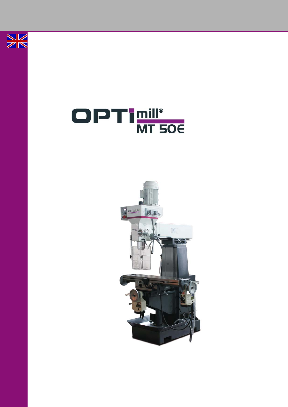
OPTIMUM
Part no. 3336010
MASCHINEN - GERMANY
Operating Manual
Version 1.0
Drilling- milling machine
GB
Page 2

OPTIMUM
MASCHINEN - GERMANY
Table of contents
1 Safety
1.1 Glossary of symbols .................................................................................................................................6
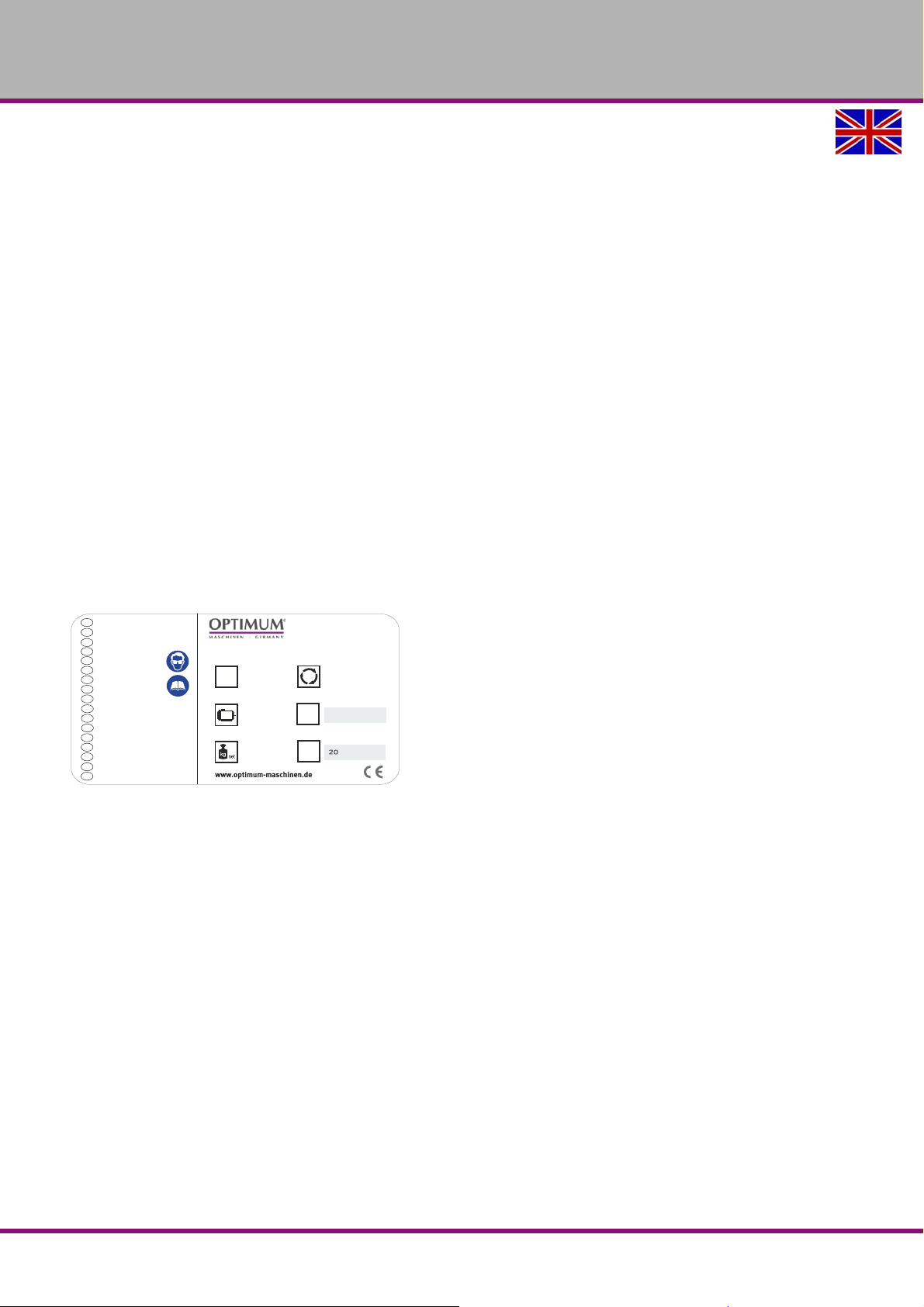
1.2 Type plate.................................................................................................................................................6
1.3 Safety instructions (warning notes)...........................................................................................................7
1.3.1 Classification of hazards ...............................................................................................................7
1.3.2 Other pictograms ...........................................................................................................................7
1.4 Intended use.............................................................................................................................................8
1.5 Reasonably foreseeable misuse...............................................................................................................9
1.5.1 Avoiding misuse............................................................................................................................9
1.6 Possible dangers caused by the milling machine.....................................................................................9
1.7 Qualification of personnel.......................................................................................................................10
1.7.1 Target group................................................................ ................................................................10
1.7.2 Authorized persons ..................................................... .................................................. ..............11
1.8 User positions.................................................................................... ... ..................................................12
1.9 Safety devices ........................................................................................................................................12
1.9.1 Lockable main switch..................................................................................................................13
1.9.2 Emergency-stop push button ......................................................................................................13
1.9.3 Control technical protection........................................................................................................13
1.9.4 Prohibition, warning and mandatory signs ..................................................................................13
1.10 Safety check...........................................................................................................................................14
1.11 Personal protective equipment...............................................................................................................14
1.12 Safety during operation...........................................................................................................................15
1.13 Safety during maintenance.....................................................................................................................15
1.14 Switching-off and securing the milling machine......................................................................................15
1.15 Using lifting equipment ...........................................................................................................................16
1.16 Mechanical maintenance work ...............................................................................................................16
1.17 Accident report........................................................................................... ... ..........................................16
1.18 Electronics..............................................................................................................................................16
1.19 Inspection deadlines...............................................................................................................................17
1.20 Clamping devices for workpieces and tools............................................................................................17
1.21 Environmental protection and water conservation................................................................. ... ... ...........17
2 Technical specification
2.1 Electrical connection...............................................................................................................................18
2.2 Spindle....................................................................................................................................................18
2.3 Cross table..............................................................................................................................................18
2.4 Travels....................................................................................................................................................18
2.5 Dimensions.............................................................................................................................................18
2.6 Work area........................................................... ................................................... .................................19
2.7 Coolant equipment...................................... ... .................................................. ... ....................................19
2.8 Environmental conditions.................................................................................... ....................................19
2.9 Emissions ...............................................................................................................................................20
3 Assembly and commissioning
3.1 Unpacking the machine..........................................................................................................................21
3.2 Accessories ............................................................................................................................................21
3.3 Transport ................................................................................................................................................21
3.4 Load suspension point............................................................................................................................22
3.5 Set-up and assembly.................................. .................................................. ... .......................................23
3.5.1 Installation plan ................................................ .................................................. .........................23
3.5.2 Requirements regarding the installation site ...............................................................................23
3.6 Machine mounting ..................................................................................................................................25
3.6.1 Anchor-free mounting..................................................................................................................25
MT50EGB
Version 1.0 dated 2017-05-24Page 2 Translation of the original instructions
Page 3

OPTIMUM
MASCHINEN - GERMANY
3.6.2 Anchored mounting.....................................................................................................................25
3.7 First commissioning................................................................................................................................26
3.8 One-component paint.............................................................................................................................27
3.9 Cleaning the machine.............................................................................................................................27
3.10 Lubrication and oil level..........................................................................................................................27
3.11 Warming up the machine .......................................................................................................................27
3.12 Electrical connection ..............................................................................................................................27
4Operation
4.1 Overview ................................................................................................................................................29
4.1.1 Control panel...............................................................................................................................29
4.2 Switching on the machine ......................................................................................................................30
4.3 Turning off the machine..........................................................................................................................30
4.4 Resetting an emergency stop situation................................................................. ... .. ............................30
4.5 Power failure, Restoring readiness for operation ...................................................................................30
4.6 Inserting tool...........................................................................................................................................30
4.7 Speed change........................................................................................................................................30
4.7.1 Speed table.................................................................................................................................31
4.8 Standard values for cutting speeds.................................. ... ...................................................................31
4.9 Spindle sleeve feed................................................................................................................................32
4.9.1 Manual spindle sleeve feed.........................................................................................................32
4.9.2 Quill fine feed..............................................................................................................................32
4.10 Moving the cross table up / down...........................................................................................................32
4.11 Moving the cross table left or right .........................................................................................................33
4.11.1 Manual travel...............................................................................................................................33
4.11.2 Automatic movement of the X axis and Y axis using the feed motor..........................................33
4.12 Swivelling the milling head................................................................ .....................................................34
4.12.1 Setting the milling head to zero position.....................................................................................34
4.13 Turning the milling head..................................................................................... ... ... ..............................34
4.14 Turning of the cross table (X axis)..........................................................................................................35
4.15 Cooling...................................................................................................................................................35
5 Maintenance
5.1 Safety.....................................................................................................................................................36
5.1.1 Preparation..................................................................................................................................36
5.1.2 Restarting....................................................................................................................................36
5.2 Inspection and maintenance ..................................................................................................................37
5.3 Repair.....................................................................................................................................................39
5.3.1 Customer service technician.......................................................................................................39
6 Ersatzteile - Spare parts - MT50E
6.1 Ersatzteilbestellung - Ordering spare parts............................................................................................40
6.2 Schaltplan - Wiring diagram...................................................................................................................40
6.3 Maschinenfuß und Säule - Base & Column ...........................................................................................40
6.4 Frästisch - Milling table...........................................................................................................................42
6.5 Fräskopf - Milling head........................................................................................................................... 44
6.6 Getriebe Fräskopf - Milling head gear....................................................................................................46
6.7 Fräsfutterschutz - Milling chuck cover....................................................................................................48
6.8 Lagerübersicht - Bearing overview .........................................................................................................49
6.9 Schaltplan - Wiring diagram...................................................................................................................50
6.10 Cooling lubricants and tanks............................................................. .....................................................53
6.10.1 Inspection plan for water-mixed cooling lubricants .....................................................................54
7 Malfunctions
8 Appendix
8.1 Copyright................................................................................................................................................59
8.2 Changes.................................................................................................................................................59
Version 1.0 dated 2017-05-24 Page 3Translation of the original instructions
MT50E GB
Page 4

OPTIMUM
MASCHINEN - GERMANY
8.3 Product follow-up....................................................................................................................................59
8.4 Liability claims for defects / warranty......................................................................................................59
8.5 Storage...................................................................................................................................................60
8.6 Advice for disposal / Options of re-use...................................................................................................61
8.6.1 Decommissioning........................................................................................................................61
8.6.2 Disposal of new device packaging..............................................................................................61
8.6.3 Disposal of the machine..............................................................................................................61
8.6.4 Disposal of electrical and electronic components .......................................................................61
8.6.5 Disposal of lubricants and coolants.............................................................................................62
8.7 Disposal through municipal collection facilities.......................................................................................62
8.8 Terminology/Glossary.............................................................................................................................62
MT50EGB
Version 1.0 dated 2017-05-24Page 4 Translation of the original instructions
Page 5

OPTIMUM
MASCHINEN - GERMANY
Preface
Dear customer,
Thank you very much for purchasing a product made by OPTIMUM.
OPTIMUM metal working machines o ffer a maximum of quality, technically optimum solutions
and convince by an outstanding price performance ratio. Continuous enhancements and product innovations guarantee state-of-the-art products and safety at any time.
Before commissioning the machine please thoroughly read these operating instructions and get
familiar with the machine. Please also make sure that all persons operating the machine have
read and understood the operating instructions beforehand.
Keep these operating instructions in a safe place nearby the machine.
Information
The operating instructions include indications for safety-relevant and proper installation, operation and maintenance of the machine. The continuous observance of all notes included in this
manual guarantee the safety of persons and of the machine.
The manual determines the intended use of the machine and includes all necessary information
for its economic operation as well as its long service life.
In the paragraph "Maintenance" all maintenance works and functiona l tests are described which
the operator must perform in regular intervals.
The illustration and information included in the present manual can possibly deviate from the
current state of construction of your machine. Being the manufacturer we are continuously
seeking for improvements and renewal of the products. Therefore, changes might be performed
without prior notice. The illustrations of the machine may be different from the illustrations in
these instructions with regard to a few details. However, this does not have any influence on
the operability of the machine.
Therefore, no claims may be derived from the indications and descriptions. Changes and errors
are reserved !
Your suggestion with regard to these operating instructions are an important contribution to
optimising our work which we offer to our customers. For any questions or suggestions for
improvement, please do not hesitate to contact our service department.
If you have any further questions after reading these operating instructions and you are
not able to solve your problem with a help of these operating instructions, please
contact your specialised dealer or directly the company OPTIMUM.
Optimum Maschinen Germany GmbH
Dr.- Robert - Pfleger - Str. 26
D-96103 Hallstadt, Germany
Email: [email protected]
MT50E_preface_GB.fm
Version 1.0 dated 2017-05-24 Page 5Translation of the original instructions
MT50E GB
Page 6
OPTIMUM
C
Optimum Maschinen
Germany GmbH
Dr.-Robert-Pfleger-Str. 26
D-96103 Hallstadt
850 kg
0.85/1.5 kW
400 V ~50 Hz
1750 U/min
NO.
SN
Year
DE
EN
ES
FR
IT
CZ
DK
FI
GR
HU
NL
PL
PT
RO
RU
SL
TR
Fräsmaschine
Milling machine
Fresadora
Fraiseuse
Fresatrice
Univerzální frézka
Freesmachine
Porajyrsin
Φρεζοδραπανο
Multifunkciós marógép
Freesmachine
Frezarka
Φ
резерный станок
Frezalni stroj
Freze Tezgahı
Màquina freadora
Maşină de frezat
MT 50E
3336010
MASCHINEN - GERMANY
1 Safety
This part of the operating instructions
expl ains the meaning and use of the warning notes included in these operating instructions,
defines the intended use of the milling machine,
points out the dangers that might arise for you or others if these instructions are not
observed,
informs you about how to avoid dangers.
In addition to these operation instructions, please observe
the applicable laws and regulations,
the statutory provisions for accident prevention,
the prohibition, warning and mandatory signs as well as the warning notes on the milling
machine.
Always keep this documentation close to the milling machine.
1.1 Glossary of symbols
provides further instructions
calls on you to act
listings
1.2 Type plate
MT50EGB
MT50E_GB_1.fm
Safety
Version 1.0 dated 2017-05-24Page 6 Translation of the original instructions
Page 7
OPTIMUM
MASCHINEN - GERMANY
1.3 Safety instructions (warning notes)
1.3.1 Classification of hazards
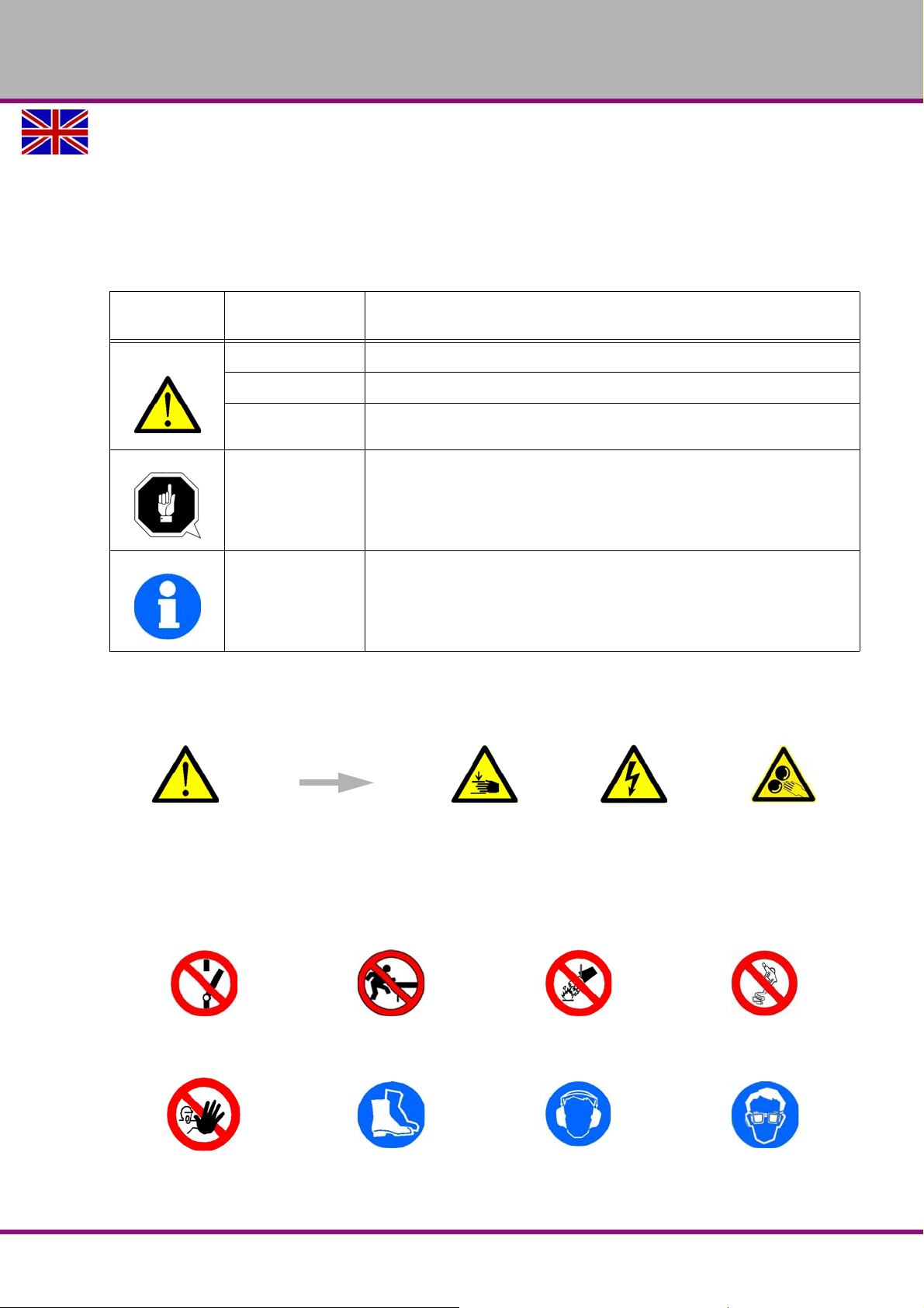
We classify the safety warnings into different categories. The table below gives an overview of
the classification of symbols (ideogram) and the warning signs for each specific danger and its
(possible) consequences.
Symbol
Alarm expres-
sion
DANGER!
WARNING!
CAUTION!
ATTENTION!
Impending danger that will cause serious injury or death to people.
A danger that can cause serious injury or death.
A danger or unsafe procedure that can cause personal injury or damage to
property.
Situation that could cause damage to the milling machine and product, as
well as other types of damage.
No risk of injury to persons.
Practical tips and other important or useful information and notes.
No dangerous or harmful consequences for people or objects.
INFORMATION
In case of specific dangers, we replace the pictogram with
Definition / consequence
general danger
with a warning of
injury to hands, hazardous electrical
voltage,
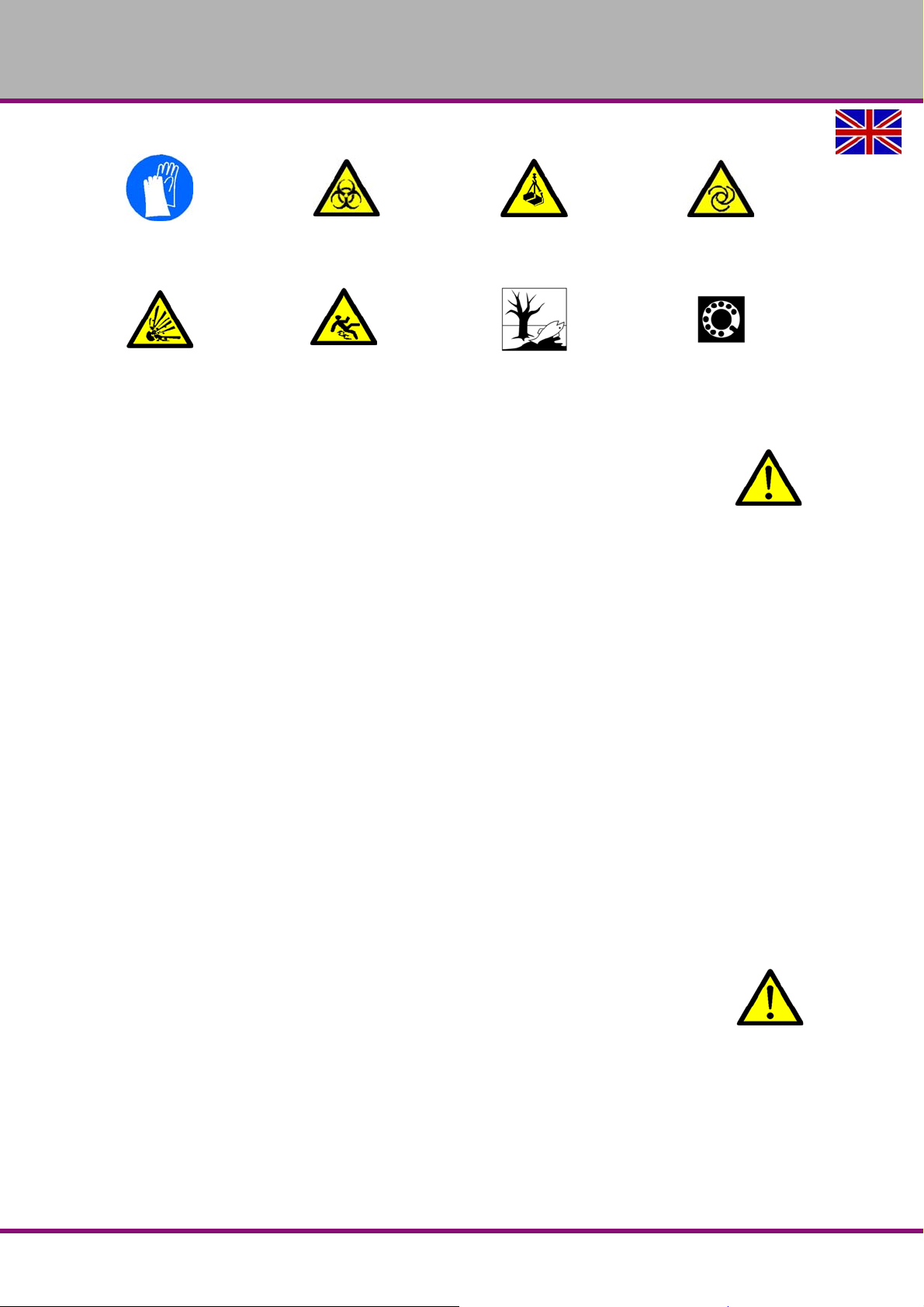
1.3.2 Other pictograms
Activation forbidden!
Access forbidden! Wear safety shoes! Use ear protection! Wear protective glasses!
MT50E_GB_1.fm
Safety
Version 1.0 dated 2017-05-24 Page 7Translation of the original instructions
Do not step into the
machine!
Do not extinguish with
water!
rotating parts.
Do not clean with com-
pressed air!
MT50E GB
Page 8
OPTIMUM
MASCHINEN - GERMANY
Wear protective gloves!
Caution, danger of explo-
sive substances!
Warning: biological hazard!
Warning: danger of slip-
ping!
Warning: suspended loads!
Protect the environment! Contact address
Warning: automatic start-
1.4 Intended use
WARNING!
In the event of improper use, the milling machine
may be a hazard to personnel,
the machine and other property of the operating company and
the functionality of the milling machine may be compromised.
The milling machine is designed and manufactured to be used for milling and drilling cold metals or other non-flammable materials or materials that do not constitute a health hazard when
commercial milling and drilling tools are used.
Using this machine it is possible to perform dry process ing as well as processing by using cooling lubricants.
The milling machine must only be installed and operated in a dry and well-ventilated areas.
The milling machine is designed and manufactured to be used in a non-explosive environment.
approval of Maschinen Germany GmbH, then the milling machine is being used improperly.
We will not be held liable for any damages resulting from any operation which is not in accord-
ance with the intended use.
We expressly point out that the guarantee or CE conformity will expire, if any constructive, tech-
nicalor procedural changes are not performed by the company Optimum Maschinen Germany
GmbH.
It is also part of the intended use that you
the limits of performance of the milling machine are observed,
the operating manual is observed,
the inspection and maintenance instructions are observed.
up!
Intended useIf the milling machine is used in any way other than described above, or modified without the
WARNING!
Extremely severe injuries due to non-intended use.
It is forbidden to make any modifications or alternations to the operating parameters
values of the milling machine. They could pose an accident hazard to persons and cause
damage to the milling machine.
MT50EGB
Version 1.0 dated 2017-05-24Page 8 Translation of the original instructions
MT50E_GB_1.fm
Safety
Page 9
OPTIMUM
MASCHINEN - GERMANY
1.5 Reasonably foreseeable misuse
Any other use other than that specified under "Intended use" or any use beyond the described
use shall be deemed as non-intended use and is not permissible.
Any other use has to be discussed with the manufacturer.
It is only permissible to process metal, cold and non-inflammable materials with the milling
machine.
In order to avoid misuse, it is necessary to read and understand the operating instructions
before first commissioning.
Operators must be qualified.
1.5.1 Avoiding misuse
Use of suitable cutting tools.
Adapting the speed setting and feed to the material and workpiece.
Clamp workpieces firmly and free of vibration.
Risk of fire and explosion due to the use of flamma b le ma te ria l s or coolin g lubr ican ts .
Before processing inflammable materials (e.g. aluminium, magnesium) or using inflammable auxiliary materials (e.g. spirit), you need to take additional preventive measures in order
to avoid health risks.
When processing carbons, graphite and carbon-fibre-reinforced carbons, the machine is no
longer being used as intended. This causes the warranty to be null and void. When
processing carbons, graphite and carbon-fibre-r einforced carbons an d similar materials, the
machine can be damaged extremely quickly, even if the dusts generated are completely
sucked out during the work process.
ATTENTION!
The workpiece is always to be fixed by a machine vice, jaw chuck or by another
appropriate clamping tool such as for the clamping claws.
WARNING!
Risk of injury caused by flying workpieces.
Clamp the workpiece in the machine vice. Make sure that the workpiece is firmly clamped in the
machine vice and that the machine vice is firmly clamped onto the machine table.
Use cooling and lubricating agents to increase the durability of the tool and to improve the
surface quality.
Clamp the cutting tools and workpieces on clean clamping surfaces.
Sufficiently lubricate the machine.
WARNING!
Do not use the drill chuck as a milling tool. Never clamp a milling cutter into a drill
chuck. Use a collet chuck with collets for the end mill.
When milling make sure that
the corresponding cutting speed is selected,
for workpieces with normal strength values, e.g. steel 18-22 m/min,
for workpieces with high strength values, 10-14 m/min,
for hard materials commercial cooling / lubricating agents are used.
1.6 Possible dangers caused by the milling machine
The milling machine has been tested for operational safety. The construction and type are state
of the art.
Nevertheless, there is a residual risk, as the milling machine operates with
MT50E_GB_1.fm
Safety
Version 1.0 dated 2017-05-24 Page 9Translation of the original instructions
MT50E GB
Page 10
OPTIMUM
MASCHINEN - GERMANY
rotating parts,
electrical voltage and currents,
and an automatic feed.
We have used design and safety engineering to minimize the health risk to personnel resulting
from these hazards.
If the milling machine is used and maintained by personnel who are not duly qualified, there
may be a risk resulting from its incorrect or unsuitable maintenance.
INFORMATION
Everyone involved in the assembly, commiss ion ing , op e ra tio n an d main te na nc e mu st
be duly qualified,
and strictly follow these operating instructions.
In the event of improper use
there ma y be a risk to personnel,
the milling machine and other property and
the functionality of the milling machine may be compromised.
Always switch off the milling machine and disconnect it from the mains, when cleaning or maintenance work is carried out.
WARNING!
The milling machine may only be used with fully functional safety devices. Disconnect
the milling machine immediately, whenever you detect a failure in the safety devices or
when they are not fitted!
All additional parts of the machine which had been added by the customer need to be
equipped with the prescribed safety devices.
This is your responsibility being the operating company!
12
"Safety devices“ on page
1.7 Qualification of personnel
1.7.1 Target group
This manual is addressed to
the operating companies,
operators having sufficient specialist knowledge,
the maintenance personnel.
Consequently, the warning notes refer both to the use of the milling machine and to its maintenance.
Determine clearly and explicitly who will be responsible for the different activities on the milling
machine (operation, setting up, maintenance and repair). Please note the name of the responsible person into an operators´s log.
INFORMATION
Unclear responsibilities constitute a safety risk!
Always lock the main switch after switching off the milling machine. This will prevent it from
being used by unauthorized persons.
The qualifications of the personnel for the different tasks are mentioned below:
Operator
The operator has been instructed by the operating company regarding the assigned tasks and
possible risks in case of improper behaviour. Any tasks which need to be performed beyond the
operation in standard mode must only be performed by the operator, if so indicated in these
MT50EGB
Version 1.0 dated 2017-05-24Page 10 Translation of the original instructions
MT50E_GB_1.fm
Safety
Page 11
OPTIMUM
MASCHINEN - GERMANY
instructions and if the operator has been expressively commissioned by the operating company.
Qualified electrician
With professional training, knowledge and experience as well as knowledge of respective
standards and regulations, qualified electricians are able to perform work on the electrical system and recognise and avoid any possible dangers.
Qualified electricians have been specially trained for the working environment, in which they are
working and know the relevant standards and regulations.
Qualified personnel
Due to their professional training, kn owledge and experience as we ll as knowledge of relevant
regulations, qualified personnel are able to perform the assigned tasks and to independently
recognise and avoid any possible dangers.
Instructed person
Instructed persons were instructed by the operating company regarding the assigned tasks and
any possible risks of improper behaviour.
1.7.2 Authorized persons
INFORMATION
Sufficient expertise is required for working on the milling machine. No one must work on
the machine without having the necessary training, not even for a short while.
WARNING!
Inappropriate operation and maintenance of the milling machine constitutes a danger to
the personnel, objects and the environment. Only authorized personnel may operate the
milling machine !
Persons authorized to operate and maintain should be trained technical personnel and
instructed by the ones who are working for the operating company and for the manufacturer.
Obligations of the operating company
train the personnel,
instruct the personnel in regular intervals (at least once a year) on
- all safety regulations relevant to the milling machine,
- operation of the milling machine,
- generally accepted engineering standards.
- possible emergency situations,
check the personnel‘s knowledge level,
document training/instruction in a operation book,
require personnel to confirm participation in training/instructions by means of a signature,
check whether the personnel is working safety and risk-conscious and observes the operat-
ing instructions.
Define and document the machine inspection deadlines in accordance with section 3 of the
Factory Safety Order and perform an operational risk analysis in accordance with section 6
of the Safety at Work Act.
Obligations of
the operating
company
Obligations of the user
have obtained a training regarding the handling of the milling machine,
keep an operator‘s log,
before taking the machine in operation
- have read and understood the operating manual,
- be familiar with all safety devices and instructions.
MT50E_GB_1.fm
Safety
Version 1.0 dated 2017-05-24 Page 11Translation of the original instructions
Obligations of
the operator
MT50E GB
Page 12
OPTIMUM
MASCHINEN - GERMANY
For work on the following milling machine parts there are additional requirements:
Electric components or operating materials: Must only be worked on by a qualified electri-
cian or person working under the instructions and supervision of a qualified electrician.
1.8 User positions
The operator position is located in front of the milling machine at the inspection window, to the
side of the automatic feed for the cross table or on the control panel.
1.9 Safety devices
The milling machine must only be operated with fully functional safety devices.
Stop the milling machine immediately if there is a failure on the safety device or becomes inef-
fective.
This is your responsibility!
If a safety device has been activated or has failed, the milling machine must only be used if you
have eliminated the cause of the fault and
you have verified that there is no danger to personnel or objects.
WARNING!
If you bypass, remove or override a safety device in any other way, you are endangering
yourself and other persons working with the milling machine. The possible
consequences include:
injuries due to tools, workpieces or fragments hereof which are flying off at high
speed,
contact with rotating or moving parts,
fatal electrocution,
pulling-in of clothes.
Additional
requirements
regarding the
qualification
WARNING!
Although the isolating safety devices provided and delivered with the machine are
designed to reduce the risks of workpieces being ejected or parts of tools or workpieces
breaking off, they cannot eliminate these risks completely. Always work carefully and
observe the limits of the machining process.
The milling machine features the following safety devices:
a lockable main switch,
an emergency stop push button,
a spindle guard,
a milling table with T-slots to fix the workpiece or the clamping device.
MT50E_GB_1.fm
MT50EGB
Version 1.0 dated 2017-05-24Page 12 Translation of the original instructions
Safety
Page 13
OPTIMUM
MASCHINEN - GERMANY
1.9.1 Lockable main switch
In the "0" position, the lockable main switch can be secured against accidental or non-authorised switching on by means of a padlock.
The power supply is cut off when the master switch is in the off position.
Except for the areas marked by the pictogram in the margin. In these areas there might be volt-
age, even if the main switch is switched-off.
WARNING!
Dangerous voltage even if the main switch is switched off.
The areas marked by the pictogram might contain live parts, even if the master switch is
switched off.
1.9.2 Emergency-stop push button
CAUTION!
Only press the emergency stop button in a genuine emergency. Do not use the
emergency stop button to stop the machine during normal operation.
ATTENTION!
If a emergency-stop push button is activated, the drives are stopped with the maximum
possible braking torque. The spindle drive continues to run for a while depending on the
moment of inertia of all components and the mass of the tool in use.
Press the emergency stop push button only if there is a risk! If this push button is
actuated in order to switch off the milling machine in the standard operation the tool or
workpiece might get damaged.
After having actuated the emergency-stop mushroom switch, turn the knob of the particular
push button to the right in order to restart the machine.
1.9.3 Control technical protection
WARNING!
If you bypass a controller you endanger yourself and other persons working on the
milling machine.
injuries due to tools, workpieces or fragments hereof which are flying off at high
speed,
contact with rotating parts,
fatal electrocution,
pulling-in of clothes.
If you temporarily bypass a controller in exceptional cases (e.g. during electrical repairs), you
must continuously monitor the milling machine.
1.9.4 Prohibition, warning and mandatory signs
INFORMATION
All warning and mandatory signs must be legible. They must be checked regularly.
MT50E_GB_1.fm
Safety
Version 1.0 dated 2017-05-24 Page 13Translation of the original instructions
MT50E GB
Page 14
OPTIMUM
MASCHINEN - GERMANY
1.10 Safety check
Check the milling machine at least once per shift. Inform the person responsible immediately of
any damage, defects or changes in the operating function.
Check all safety devices
at the beginning of each shift (when the machine is operated continuously),
once per day (during one-shift operation),
once per week (when operated occasionally),
after all maintenance and repair work.
Check that prohibition, warning and information signs and the labels on the milling machine
are legible (clean them, if necessary)
and complete (replace them, if necessary).
INFORMATION
Organise the checks according to the following table;
General check
Equipment Check OK
Signs, Markings Installed and legible
Date: Checked by (signature):
Functional check
Equipment Check OK
Emergency stop
push button
Spindle guard The spindle drive can only be switched on if the spindle
Date: Checked by (signature):
After actuating an emergency stop push button the milling machine must be switched off.
guard is in the machining position.
1.11 Personal protective equipment
For certain work personal protective equipment is required.
Protect your face and your eyes: Wear a safety helmet with facial protection when performing
work where your face and eyes are exposed to hazards.
Wear protective gloves when handling pieces or tools with sharp edges.
Wear safety shoes when you assemble, disassemble or transport heavy components.
Use ear protection if the noise level (emission) in the workplace exceeds 80 dB (A).
Before starting work make sure that the required personal protective equipment is available at
the work place.
CAUTION!
Dirty or contaminated personnel protective equipment can cause illness. It must be
cleaned after each use and at least once a week.
MT50EGB
Version 1.0 dated 2017-05-24Page 14 Translation of the original instructions
MT50E_GB_1.fm
Safety
Page 15
OPTIMUM
MASCHINEN - GERMANY
1.12 Safety during operation
WARNING!
Before switching the milling machine on, make sure that there is no risk of personal
injury or damage to property.
Avoid any unsafe work methods:
The instructions mentioned in these operating instructions have to be strictly observed dur-
ing assembly, operation, maintenance and repair.
Do not work on the milling machine, if your concentration is reduced, for example, because
you are taking medication.
Clamp the workpiece securely and firmly before switching on the milling machine.
WARNING!
When chipping magnesia materials (aluminium-/magnesium alloys), spontaneously
inflammable or explosive particles (powder, dust, chips) might be generated, which
might cause a fire and/or explosion (deflagration).
Magnesium is designated a dangerous material in the list of dangerous materials and
preparations according to para. 4a of the Ordinance of Hazardous Substances.
In case of a fire with magnesium, only use appropriate and admitted extinguishing
agents. Never extinguish using water. If burning magnesium is extinguished with water,
this might lead to dangerous reactions (hydrogen gas). Water would be decomposed in
its components hydrogen (H) and oxygen (O).
Only the following extinguishing agents are permissible:
solid extinguishing agent of fire class D (fires involving metals)
dry cover ing salts for magnesium
a mixture of sand and cast chips
argon (Ar) or nitrogen (N
If fine mist and smoke is generated at the workplace, suction units must be provided in
order to avoid the accumulation of ignitable mixtures and emissions.
We specifically point out the dangers in the description of work with and on the drilling machine.
)
2
1.13 Safety during maintenance
Inform the operators in good time of any maintenance and repair works.
Report all safety relevant changes and performance details of the milling machine or their oper-
ational behaviour. Any changes must be documented, the operating instructions updated and
machine operators instructed accordingly.
1.14 Switching-off and securing the milling machine
Turn off the main switch of the milling machine before starting any maintenance or repair work.
Use a padlock to prevent the switch fro m being turned on without authorization and keep the
key in a safe place.
All machine parts as well as all dangerous voltages are switched off.
Excepted are only the positions which are marked with the adjoining pictogram. These positions
may be live, even if the main switch is switched off.
Place a warning sign on the milling machine.
WARNING!
Live parts and moves of machine parts can injure you or others dangerously!
Proceed with extreme caution if you
the milling machine due to required works (e.g. functional control).
MT50E_GB_1.fm
Safety
Version 1.0 dated 2017-05-24 Page 15Translation of the original instructions
MT50E GB
Page 16

OPTIMUM
MASCHINEN - GERMANY
1.15 Using lifting equipment
WARNING!
The use of unstable lifting and load suspension equipment that might break under load
can cause severe injuries or even death. Observe the accident prevention regulations
issued by your Employers Liability Insurance Association or other supervisory
authorities responsible for your company.
Check that the lifting and load-suspension equipment are of sufficient load-bearing
capability and are in perfect condition.
Fasten the loads carefully.
Never walk under suspended loads!
1.16 Mechanical maintenance work
Remove or install protection safety devices before starting or after completing any maintenance work; this include:
covers,
safety instructions and warning signs,
grounding cables.
If you remove protective or safety devices, re-fit them immediately after the completing the
work.
Check if they are working properly!
1.17 Accident report
Inform your supervisors and Optimum Maschinen Germany GmbH immediately in the event of
accidents, possible sources of danger and any actions which almost led to an accident (near
misses).
There are many possible causes for "near misses".
The sooner they are notified, the quicker the causes can be eliminated.
INFORMATION
We provide information about the specific dangers when working with and on the milling
machine in the descriptions for these types of work.
1.18 Electronics
Have the machine and/or the electric equipment checked regularly. Immediately eliminate all
defects such as loose connections, defective wires, etc.
A second person must be present during work on live components to disconnect the power in
the event of an emergency. Disconnect the machine immediately if there is a malfunction in the
power supply!
Comply with the required inspection intervals in accordance with the factory safety directive,
operating equipment inspection.
The operator of the machine must ensure that the electrical systems and operating equipment
are inspected with regards to their proper condition, namely,
by a qualified electrician or under the supervision and direction of a qualified electrician,
prior to initial commissioning and after modifications or repairs, prior to recommissioning
and at set intervals.
The intervals must be set so that foreseeable defects can be detected in a timely manner, when
they occur.
The relevant electro-technical rules must be followed during the inspection.
MT50E_GB_1.fm
MT50EGB
Version 1.0 dated 2017-05-24Page 16 Translation of the original instructions
Safety
Page 17
OPTIMUM
MASCHINEN - GERMANY
The inspection prior to initial commissioning is not required if the operator receives confirmation from the manufacturer or installer that the electrical systems and operating equipment comply with the accident prevention regulations, see conformity declaration.
Permanently installed electrical systems and operating equipment are considered constantly
monitored if they are continually serviced by qualified electricians and inspected by means of
measurements in the scope of operation (e.g. monitoring the insulation resistance).
1.19 Inspection deadlines
Define and document the inspection deadlines for the machine in accordance with § 3 of the
Factory Safety Act and perform an operational risk analysis in accordance with § 6 of the Work
Safety Act. Also use the inspection intervals in the maintenance section as reference values.
1.20 Clamping devices for workpieces and tools
ATTENTION!
Attention when taking over existing clamping devices. Pleased thoroughly check that
the clamping device is appropriate for your milling machine.
Only use clamping devices with a complete inherent rigidity.
Contact the manufacturer of the clamping device regarding the reuse of clamping
devices after damage to the clamping device due to collisions.
Correctly insert the workpiece and make sure that the machine is proper working
condition.
1.21 Environmental protection and water conservation
The milling machine is a device to produce, handle and use materials which are hazardous to
water according to para. 19g of the Water Resources Law.
Please follow the requirements of the Water Resources Law when operating, decommissioning
or disassembling the milling machine or parts hereof. Detailed information regarding this can be
found in the Ordinance on Installations for the Handling of Substances Hazardous to Water
(VAwS).
MT50E_GB_1.fm
Safety
Version 1.0 dated 2017-05-24 Page 17Translation of the original instructions
MT50E GB
Page 18
OPTIMUM
44.45
17
M16
68.4
15.9
19.1
35
22.8 25
16.1
48
63.55
MASCHINEN - GERMANY
2 Technical specification
The following information represents the dimensions and indications of weight and the manufacturer‘s approved machine data.
2.1 Electrical connection
Total connection 3 x 400V ~ 50Hz (60 Hz)
Fusing performed by the operator 16 A
2.2 Spindle
Drive motor 0.85 / 1.5 kW
Operating mode and duty cycle S6 - 60%
Speed 115 - 1750 rpm
Gear stages / motor stages 4 / 2
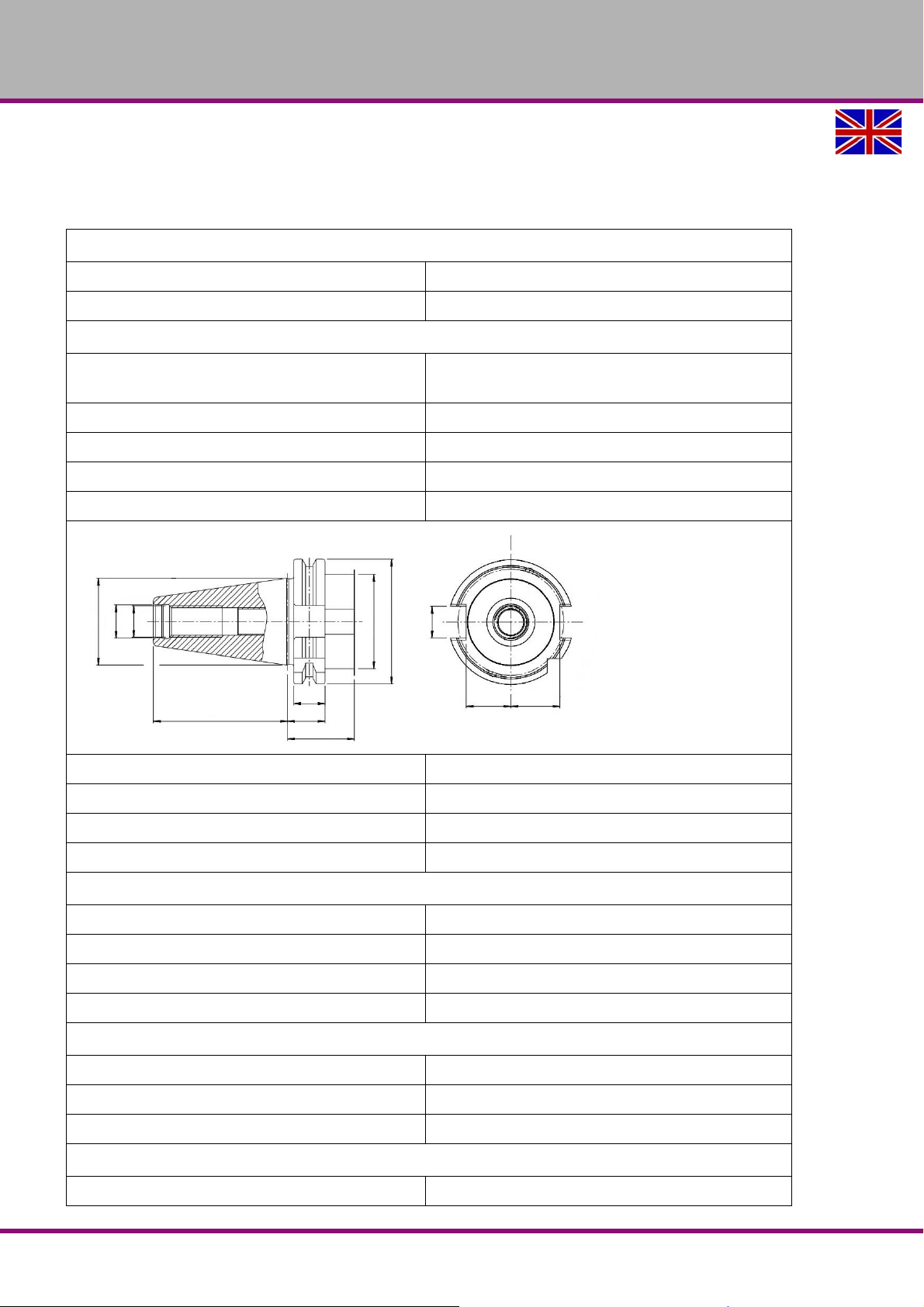
Spindle seat SK40 DIN 69871
Draw bar M16
2.3 Cross table
2.4 Travels
X axis automatic / manual [mm] 520 / 600
Y axis automatic / manual [mm] 150 / 230
2.5 Dimensions
Spindle sleeve travel [mm] 120
Throat [mm] 250 - 650
Distance spindle - table [mm] 60 -360
Inclination of milling head ± 45°
Table size [ mm ] 1000 x 240
max. load of cross table [ kg ] 150
T-slot size / number 14mm / 4
Rotatable
Z axis manual [mm] 400
"Installation plan“ on page 23
MT50E_GB_2.fm
MT50EGB
Technical specification
Version 1.0 dated 2017-05-24Page 18 Translation of the original instructions
Page 19

OPTIMUM
MASCHINEN - GERMANY
Total weight [kg] 900
2.6 Work area
Keep a work area of at least one metre around the machine free for operation and maintenance.
2.7 Coolant equipment
Power of the cooling lubricant pump [ W ] 40 W
Capacity cooling lubricant tank [ L ] 8
Delivery height [ meter ] 3
2.8 Environmental conditions
Temperature 19 - 21 °C (for an optimum milling result)
permissible range + 10° to + 35°C
Admissible relative humidity 5...90 % no condensation
30% to 90% at 35°C
90 % at 21°C
Compressed air 700...1060 hPa
Environmental conditions - storage 5 - 45 °C
MT50E_GB_2.fm
Technical specification
Version 1.0 dated 2017-05-24 Page 19Translation of the original instructions
MT50E GB
Page 20
OPTIMUM
MASCHINEN - GERMANY
2.9 Emissions
Measurement in operating conditions in accordance with DIN ISO 8525 with surface areas
Measurement methods in accordance with DIN 45635.
The generation of noise emitted by the machine is 80 dB(A) on no-load running at 80% of max.
spindle speed and activated automatic feed on no-load running at 80% of the possible feed
speed, measured at a distance of one meter from the machine and at a height of 1.6m.
If the milling machine is installed in an area where various machines are in operation, the noise
exposure (immission) on the operator of the milling machine at the working place may exceed
80 dB(A).
INFORMATION
This numerical value was measured on a new machine under the operating conditions specified
by the manufacturer. The noise behaviour of the machine might change depending on the age
and wear of the machine.
Furthermore, the noise emission also depends on production engineering factors, e.g. speed,
material and clamping conditions.
INFORMATION
The specified numerical value represents the emission level and does not necessarily a safe
working level.
Though there is a dependency between the degree of the noise emission and the degree of the
noise disturbance it is not possible to use it reliably to determine if further precaution measures
are required or not.
The following factors influence the actual degree of the noise exposure of the operator:
Character istics of the working area, e.g. size or damping behaviour,
other noise sources, e.g. the number of machines,
other processes taking place in proximity and the period of time, during which the operator
is exposed to the noise.
Furthermore, it is possible that the admissible exposure level might be different fr om country to
country due to national regulations.
This information about the noise emission should, however, allow the operator of the machine
to more easily evaluate the hazards and risks.
CAUTION!
Depending on the overall noise exposure and the basic threshold values, machine
operators must wear appropriate hearing protection.
We generally recommend the use of noise and ear protection.
MT50EGB
Technical specification
Version 1.0 dated 2017-05-24Page 20 Translation of the original instructions
MT50E_GB_2.fm
Page 21
OPTIMUM
MASCHINEN - GERMANY
3 Assembly and commissioning
INFORMATION
The milling machine is delivered pre-assembled. It is delivered in a transport box. After the
unpacking and the transportation to the installation site it is necessary to mount and assemble
the individual components of the milling machine.
3.1 Unpacking the machine
Install the machine close to its final position before unpacking. If the packaging shows signs of
having possibly been damaged during transport, take the appropriate precautions to prevent
the machine being damaged when unpack ing. If damage is disco vered, the carrier and /or shipper must be notified immediately so the necessary steps can be taken to register a complaint.
Examine the complete machine carefully and check whether all materials, such as shipping
documents, instructions and accessories have been delivered with the machine.
3.2 Accessories
Draw bar
Key type drill chuck
Arbor drill chuck ISO40 / B18
T-nuts
Drill drift
Adapter SK40 - MT3
Adapter MT3 - MT2
Operating tool
3.3 Transport
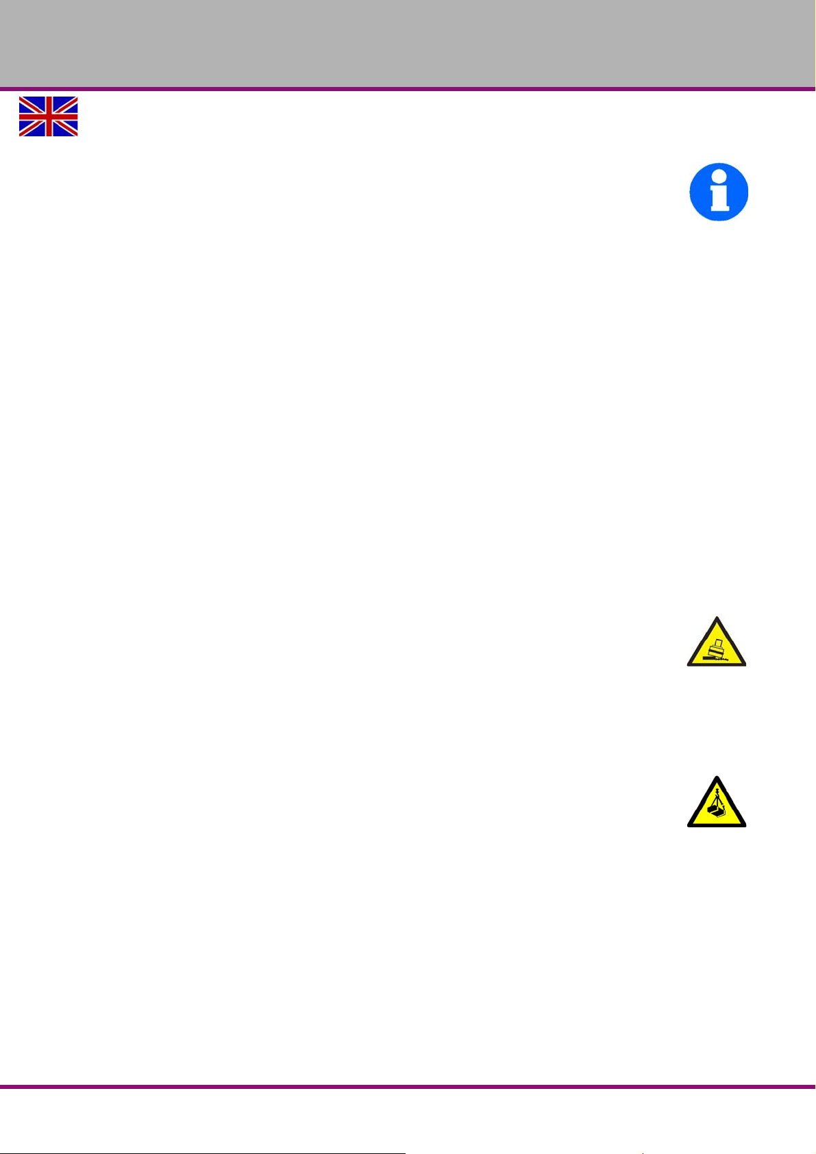
WARNING!
Severe or fatal injuries may occur if parts of the machine tumble or fall down from the
forklift truck or from the transport vehicle. Follow the instructions and information on
the transport box.
Note the total weight of the milling machine.
Only use transport devices and load suspension gear that can hold the total weight of
the milling machine.
WARNING!
The use of unstable lifting and load suspension equipment that might break under load
can cause severe injuries or even death. Check that the lifting and load suspension gear
has sufficient load-bearing capacity and that it is in perfect condition.
Observe the accident prevention regulations issued by your Employers Liability
Insurance Association or other supervisory authorities applicable to your company.
Fasten the loads carefully.
Never walk under suspended loads!
Weights
"Installation plan“ on page 23
Weight of the milling machine “Total weight [kg]“ on page 19
MT50E_GB_3.fm
Assembly and commissioning
Version 1.0 dated 2017-05-24 Page 21Translation of the original instructions
MT50E GB
Page 22
OPTIMUM
1.5 t
MASCHINEN - GERMANY
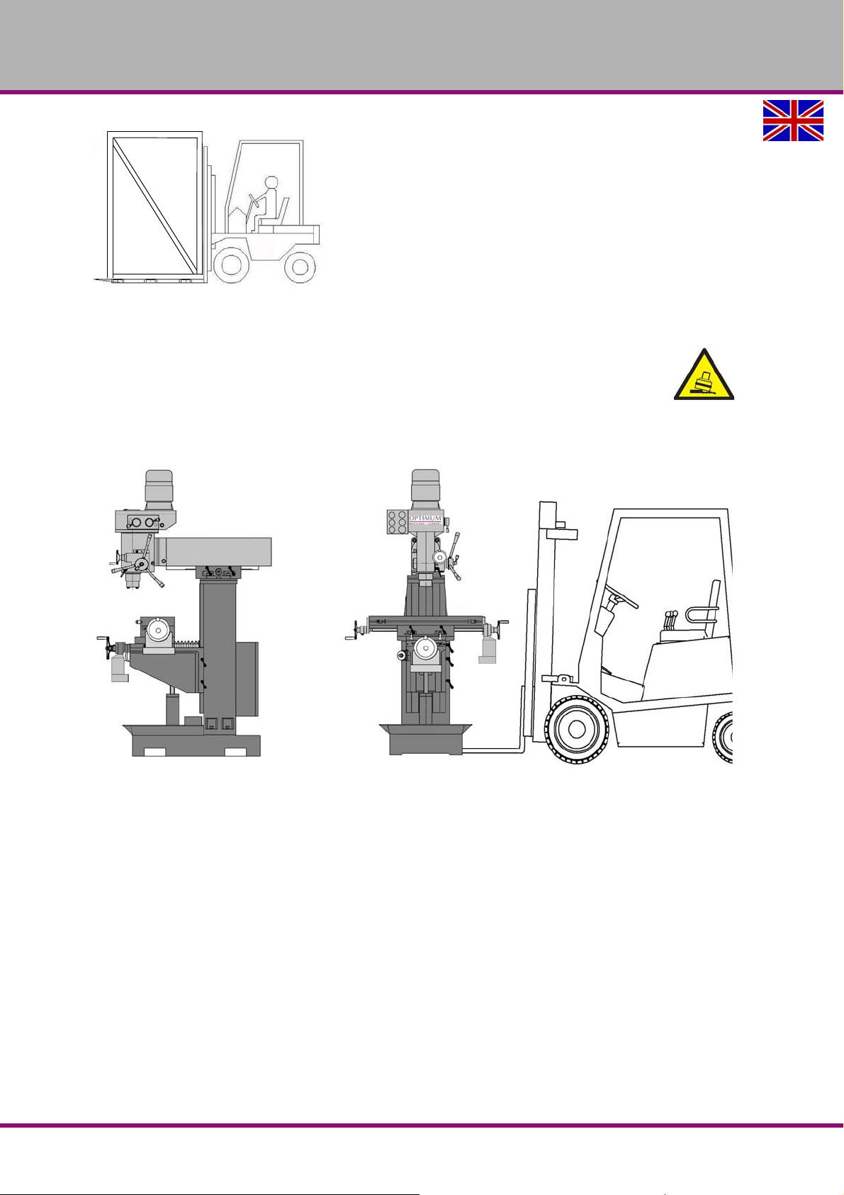
3.4 Load suspension point
WARNING!
Before lifting the milling machine, check that all clamping screws of the milling table and
the spindle head are tightened.
The milling machine is lifted with a forklift on the machine base.
The clamping screws of the milling table and the spindle head bearing must be tightened.
Img.3-1: Load suspension point
MT50E_GB_3.fm
MT50EGB
Assembly and commissioning
Version 1.0 dated 2017-05-24Page 22 Translation of the original instructions
Page 23
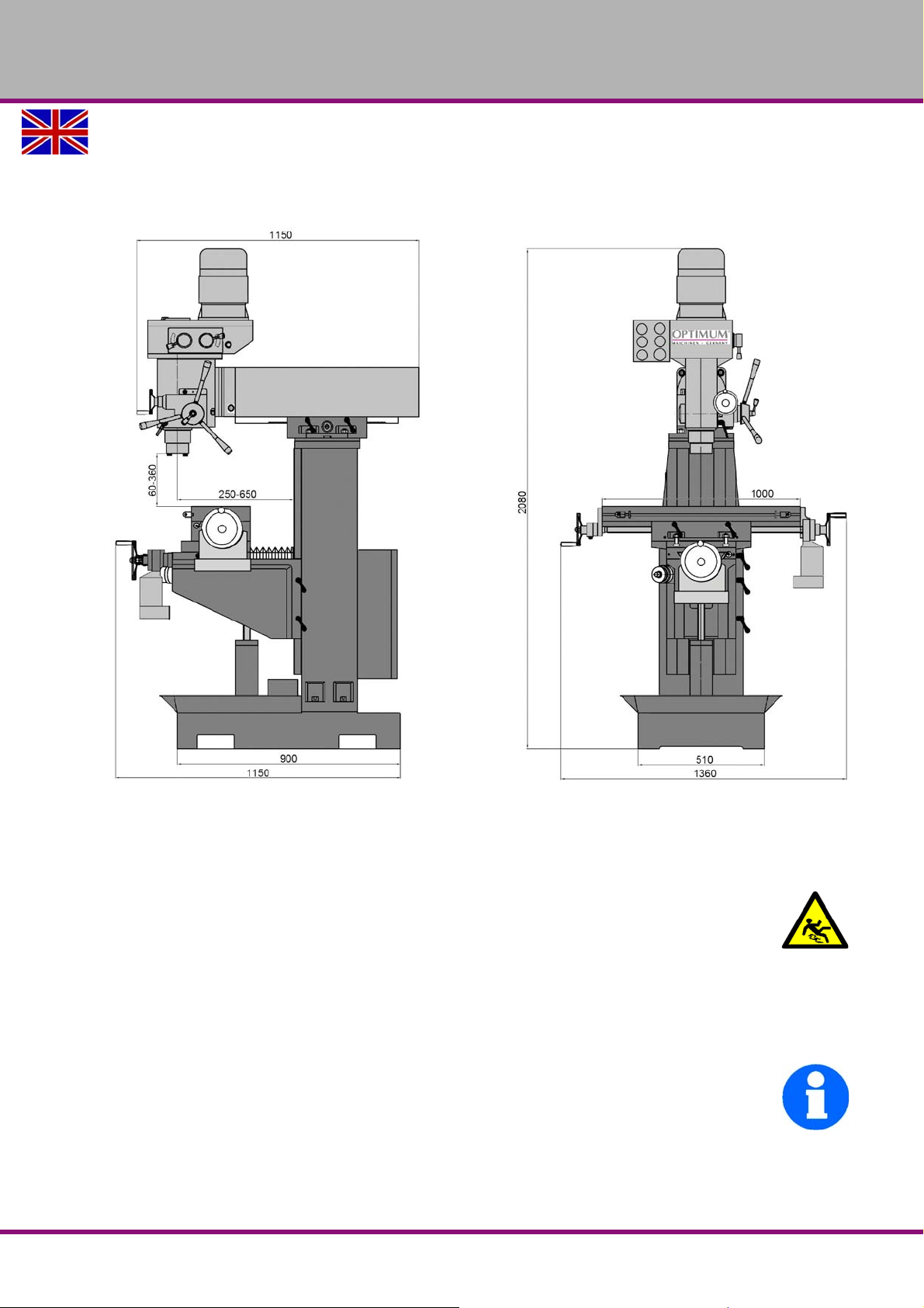
3.5 Set-up and assembly
3.5.1 Installation plan
OPTIMUM
MASCHINEN - GERMANY
3.5.2 Requirements regarding the installation site
Keep a work area of at least one metre around the machine free for operation and maintenance.
In order to achieve sufficient safety against falls by slipping, the accessible area in the mechanical machining zone of the machine must be equipped with a slip resistance. The slip-resistant
mat and/or slip-resistant flooring must be at least R11 in accordance with BGR 181. The determination of this requirement resulted in the risk assessment of the machine.
The used shoes must be suitable for being used in those machining areas. The accessible surfaces must be cleaned.
Organise the working area around the milling machine machine according to the local safety
regulations.
INFORMATION
In order to achieve high levels of functionality and machining accuracy, as well as a long
service life of the machine, the set-up location should meet certain criteria.
The following points should be noted:
The device must only be installed and operated in a dry and well-ventilated place.
Avoid places close to machines which cause chips or dust.
MT50E_GB_3.fm
Assembly and commissioning
Version 1.0 dated 2017-05-24 Page 23Translation of the original instructions
MT50E GB
Page 24

OPTIMUM
MASCHINEN - GERMANY
The installation site must be vibration-free, i.e. located away from presses, planing
machines, etc.
The foundation must be suitable for the milling machine. Pay attention also to the load-bear-
ing capacity and evenness of the floor.
The substru cture m ust b e prepa re d in such a wa y a s to ensure that, if any lubricant is used,
it cannot penetrate the floor.
Protruding parts - such as the dog, handles, etc. - must be secured, where necessary, by
means of on-site measures so that persons are not endangered.
Provide enough space for set-up and operating personnel and material transport.
Also bear in mind accessibility for installation and maintenance works.
Ensure ad equate lighting is availab le (minimum va lue : 500 Lux, mea sured at th e tool tip). In
the event of a lower level of lighting, additional illumination must be provided, e.g. by means
of a separate workplace light.
INFORMATION
The main switch of the milling machine must be freely accessible.
MT50E_GB_3.fm
MT50EGB
Assembly and commissioning
Version 1.0 dated 2017-05-24Page 24 Translation of the original instructions
Page 25
OPTIMUM
840
130
4 - 80x80
455
710
1100
250 - 300
190
DIN 529 M12 x 320
400 - 500
840
MASCHINEN - GERMANY
3.6 Machine mounting
3.6.1 Anchor-free mounting
This must be done by laying down a strong base, on each support of the levelling points,
between the foundation and the machine foot.
3.6.2 Anchored mounting
Use an anchored mounting to achieve a rigid connection to the substructure. An anchored
mounting is always appropriate if the intention is to machine large parts up to the maximum
capacity of the drilling-milling machine.
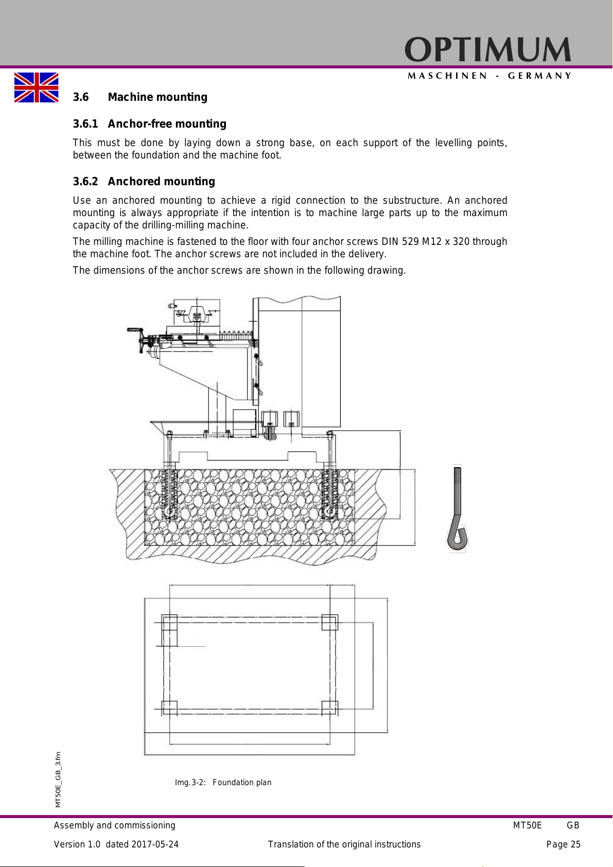
The milling machine is fastened to the floor with four anchor screws DIN 529 M12 x 320 through
the machine foot. The anchor screws are not included in the delivery.
The dimensions of the anchor screws are shown in the following drawing.
MT50E_GB_3.fm
Assembly and commissioning
Img.3-2: Foundation plan
MT50E GB
Version 1.0 dated 2017-05-24 Page 25Translation of the original instructions
Page 26
OPTIMUM
MASCHINEN - GERMANY
Drilled core holes with a diameter of 80mm and a depth of 250mm to 300mm are provided
in the foundation.
Raise the machine from the floor and centre in the inner drill holes with the anchor screws.
Roughly align the machine.
Fill the drill holes with concrete and allow to set.
Aligning the machine
Place a machine spirit level (0.04mm/m) on the cross table.
Attach washers and nuts to the anchor screws.
Check the alignment of the milling machine with a machine spirit level on the cross table
and place base plates underneath th e ma ch in e foo t.
ATTENTION!
All four corners of the machine foot must lie flat. The maximum height difference of the
bearing surfaces after tightening the anchor screws should not exceed 0.04mm per
1000mm. We recommend using a machine spirit level to align the milling machine.
The the anchor screw nuts.
Check the alignment of the milling machine again. Re-check the alignment after a few days
of use.
3.7 First commissioning
WARNING!
Commissioning should only take place after proper installation of the machine.
First commissioned of the milling machine by inexperienced personnel constitute a risk
to personnel and equipment.
We do not accept any liability for damages caused by incorrectly performed
commissioning.
"Qualification of personnel“ on page 10
WARNING!
The use of improper tool holders or their operation at inadmissible speeds constitutes a
hazard.
Only use the tool holders (e.g. drill chuck) which were delivered with the machine or
which are offered as optional equipment by OPTIMUM.
Only use tool holders in the intended admissible speed range.
Tool holders may only be modified in compliance with the recommendation of
OPTIMUM or of the manufacturer of the clamping devices.
ATTENTION!
Before commissioning the machine, all bolts, fastenings and protections must be
checked and retightened as necessary!
MT50E_GB_3.fm
MT50EGB
Assembly and commissioning
Version 1.0 dated 2017-05-24Page 26 Translation of the original instructions
Page 27
OPTIMUM
MASCHINEN - GERMANY
3.8 One-component paint
The machine is lacquered with a one-component paint. Take this criterion into account when
selecting your cooling lubricant and cleaning the machine.
A one-component paint with added solvent sets when the solvent evaporates.
As soon as the paint is applied, the solvent escapes into the air. The binding agent becomes
felted and a dry film is formed. This process is reversible, i.e. the binding agent can always be
re-softened.
A two-component paint also consists of binding agent and solvent. However, the paint only
dries when a setting agent is added. This process is not reversible, i.e. the binding agent cannot be re-softened.
The company Optimum Maschinen Germany GmbH does not assume any guarantee for subsequent damages due to unsuitable cooling lubricants.
3.9 Cleaning the machine
ATTENTION!
Do not use compressed air to clean the machine.
Your new milling machine must be completely cleaned after unpacking to ensure that the moving parts and sliding surfaces cannot be damaged when the machine is operated. Prior to delivery, all blank parts and sliding surfaces in each unit are appropriately lubricated to protect
against rust in the period before commissioning. Remove all wrappings and clean all surfaces
with a degreaser to soften and remove protective greases and coatings.
Wipe all surfaces with a clean cotton cloth and lubricate the milling machine in accordance with
the maintenance section
power and putting the machine into service.
"Inspection and maintenance“ on page 37 before switching on the
3.10 Lubrication and oil level
During the initial lubrication and greasing of your new milling machine, the oil levels are
checked and the machine lubricated after cleaning. Only when this has been done can commissioning of the machine proceed.
"Inspection and maintenance“ on page 37
3.11 Warming up the machine
ATTENTION!
If the milling machine and in particular the milling spindle is immediately operated at
maximum load when it is cold it may result in damages.
If the machine is cold, e.g. directly after h aving transported the machine, it shoul d be warmed
up at a spindle speed of only 500 1/min for the first 30 minutes.
3.12 Electrical connection
CAUTION!
Lay the connection cable to the electrical cabinet and the cable of the coded connector
from the machine to the electrical cabinet in such a way as to prevent a trip hazard.
WARNING!
The three-phase electrical connection may only be performed by an electrician or under
the guidance and supervision of an electrician.
Please check that the type of current, voltage and protection fuse correspond to the values
specified. A protective earth ground wire connection must be available.
Min. terminal cross-section per phase and grounding: 1.5 mm
MT50E_GB_3.fm
2
Assembly and commissioning
Version 1.0 dated 2017-05-24 Page 27Translation of the original instructions
MT50E GB
Page 28

OPTIMUM
MASCHINEN - GERMANY
Electric connected load: 2 KVA
Permissible voltage fluctuations in normal operation: +6% -10% Volt
Permissible frequency fluctuations: ± 1Hz (50/60 Hz)
Permissible phase imbalance: 3% or less
ATTENTION!
Ensure that all 3 phases (L1, L2, L3) and the ground wire are connected correctly.
The neutral conductor (N) of its power supply is not connected.
ATTENTION!
Check if the drive motor is turning in the correct rotation direction. If necessary, two
phase connections must be swapped.
In the event of an incorrect rotation direction, machine components may be dama ged.
The guarantee will become null and void if the machine is connected incorrectly.
Check the fusing (fuse) of your electrical supply according to the technical instructions
regarding the total connected power of the m achin e.
Firmly connect the machine.
Please check that the type of current, voltage and protection fuse correspond to the values
specified. A protective earth ground wire connection must be available.
Main Fuse 16A.
MT50E_GB_3.fm
MT50EGB
Assembly and commissioning
Version 1.0 dated 2017-05-24Page 28 Translation of the original instructions
Page 29
4 Operation
6
2
4
5
7
10
8
1
3
9
Control ON
Coolant pump
Emergency stop
Rotational direction spindle
Spindle stop
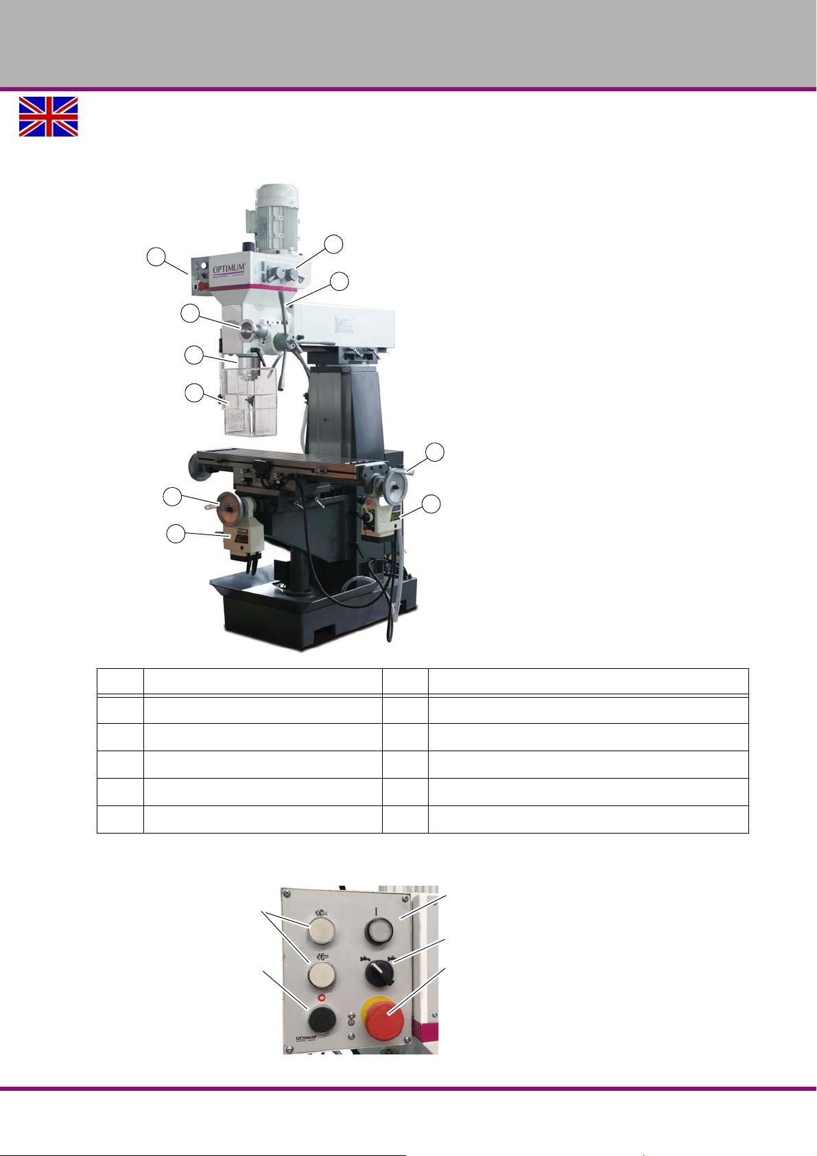
4.1 Overview
OPTIMUM
MASCHINEN - GERMANY
Pos. Designation Item Designation
1
2
3
4
5
4.1.1 Control panel
MT50E_GB_4.fm
Control panel
Spindle
Table feed Y axis
Y axis handwheel for cross table
Spindle guard
6
7
8
9
10
Spindle sleeve lever
Table feed X axis
Spindle gear
X axis handwheel for cross table
Quill fine feed
Operation
Version 1.0 dated 2017-05-24 Page 29Translation of the original instructions
MT50E GB
Page 30
OPTIMUM
Step switch
Main switch
MASCHINEN - GERMANY
4.2 Switching on the machine
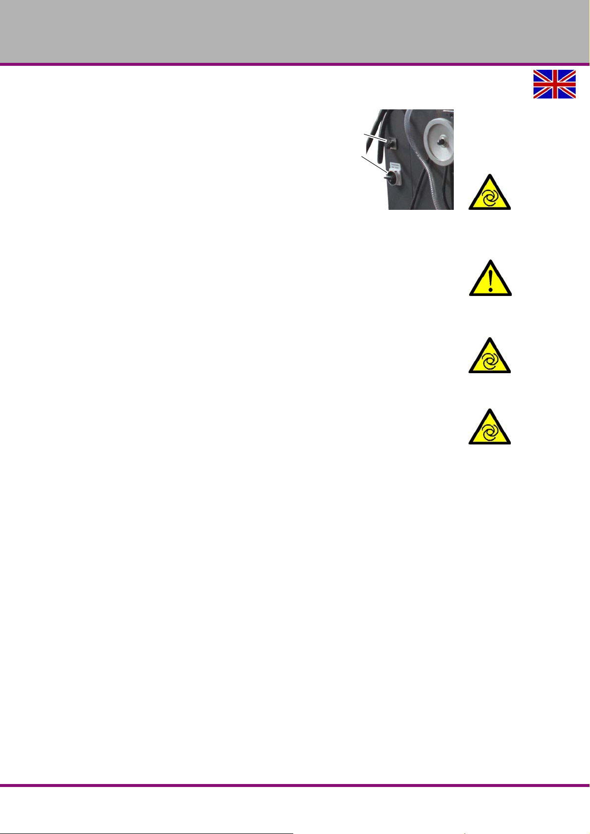
Turn the main switch to the "On" position. The
main switch is located on the distribution cabinet.
Set the step switch to the desired position. The
step switch is located on the distribution cabinet.
Set the direction lever for the table feed to the
neutral position.
Switch on the control voltage.
4.3 Turning off the machine
CAUTION!
Only press the emergency stop button in a genuine emergency. You should not use the
emergency-stop button to stop the machine during normal operation.
Switch the main switch to the position „OFF“ / 0 , lock if necessary.
4.4 Resetting an emergency stop situation
Unlock the emergency stop switch again.
Set the direction lever for the table feed to the neutral position.
Switch on the control voltage.
Switch on the spindle rotation again.
4.5 Power failure, Restoring readiness for operation
Set the direction lever for the table feed to the neutral position.
Switch on the control voltage.
4.6 Inserting tool
The milling spindle is equipped with a SK40 capture and draw bar M16.
Clean the conical seat in the milling head.
Clean the cone of your tool.
Check that the driving blocks are firmly seated.
Put the tool holder with tool from below into the steep taper of the milling spindle.
Screw the draw bar in the cone of the tool holder.
Tighten the tightening nut.
4.7 Speed change
Set the gearbox to the desired position at standstill. Set the motor step switch on distribution
cabinet to the desired position.
MT50EGB
MT50E_GB_4.fm
Operation
Version 1.0 dated 2017-05-24Page 30 Translation of the original instructions
Page 31
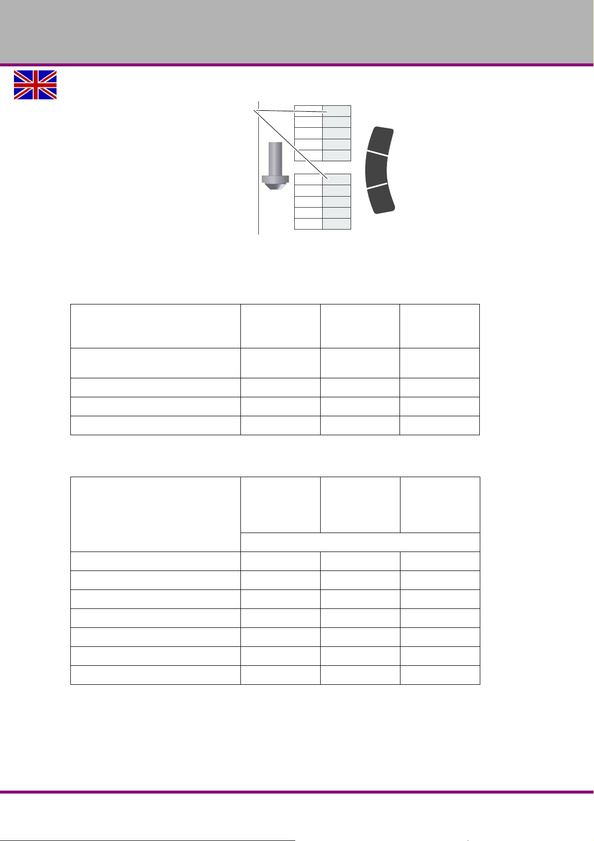
4.7.1 Speed table
Master Labels
AD
1750
AC
BD
580
720
B
0
A
AD
875
L
BC
AC
BD
115
290
360
H
BC
230
C
B
A
0
Drive step switch
Img.4-1: Speed table
4.8 Standard values for cutting speeds
[m/min] with high-speed steel and hard metal for upcut milling.
Tool Steel Grey cast iron
OPTIMUM
MASCHINEN - GERMANY
Al alloy
case-hard-
ened
Plain milling cutters and shell end mills
[m/min]
Relieved milling cutters [m/min] 15 - 24 10 - 20 150 - 250
Cutter head with SS [m/min] 15 - 30 12 - 25 200 - 300
Cutter head with HM [m/min] 100 - 200 30 - 100 300 - 400
This results in the following standard speeds, dependent on
mill diameter, mill type and material.
Tool diameter [ mm ] shell end
mill, helical milling cutter
35 91 - 227 91 - 200 1364 - 3183
40 80 - 199 80 - 175 1194 - 2785
45 71 - 177 71 - 156 1061 - 2476
50 64 - 159 64 - 140 955 - 2228
55 58 - 145 58 - 127 868 - 2025
10 - 25 10 - 22 150 - 350
Steel
10 - 25 m/min
Grey cast iron
10 - 22 m/min
Speed [rpm]
Al-alloy hard-
ened
150 - 350
m/min
60 53 - 133 53 - 117 796 - 1857
65 49 - 122 49 - 108 735 - 1714
MT50E_GB_4.fm
Operation
Version 1.0 dated 2017-05-24 Page 31Translation of the original instructions
MT50E GB
Page 32
OPTIMUM
Lever
MASCHINEN - GERMANY
Tool diameter
[mm]
Form mills
4 1194 - 1911 796 - 1592 11937 - 19894
5 955 - 1529 637 - 1274 9549 - 15916
6 796 - 1274 531 - 1062 7958 - 13263
8 597 - 955 398 - 796 5968 - 9947
10 478 - 764 318 - 637 4775 - 7958
12 398 - 637 265 - 531 3979 - 6631
14 341 - 546 227 - 455 3410 - 5684
16 299 - 478 199 - 398 2984 - 4974
Steel
15 - 24 m/min
Grey cast iron
10 - 20 m/min
Speed [rpm]
Al-alloy hard-
ened
150 - 250
m/min
4.9 Spindle sleeve feed
4.9.1 Manual spindle sleeve feed
Actuate the quill lever in order to manually lift respectively lower the quill.
You can se t the spindle sleeve to a given height using the tightening lever.
ATTENTION!
For all movements of the spindle sleeve you must first loosen the tightening lever!
4.9.2 Quill fine feed
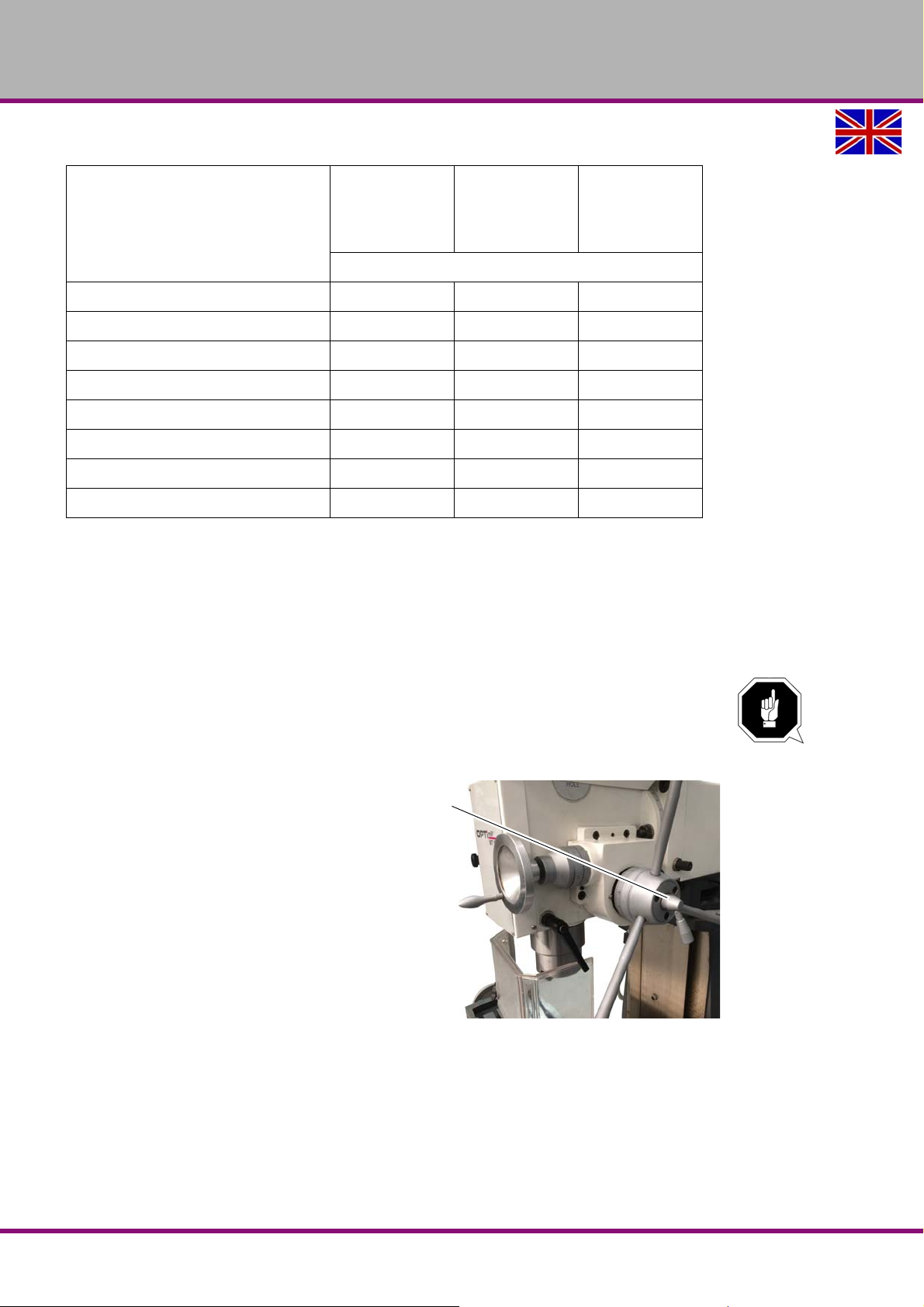
Turn the lever clockwise. The sleeve
lever moves to the spindle head and activates the coupler of the fine feed.
Turn the quill fine feed handwheel in
order to move the quill.
4.10 Moving the cross table up / down
Manual movement on the Z axis
The height adjustment of the milling table is carried out with the hand crank.
Loosen the clamping lever.
Engage the hand crank by pressing into the coupling.
MT50EGB
Img.4-2: Fine feed
MT50E_GB_4.fm
Operation
Version 1.0 dated 2017-05-24Page 32 Translation of the original instructions
Page 33
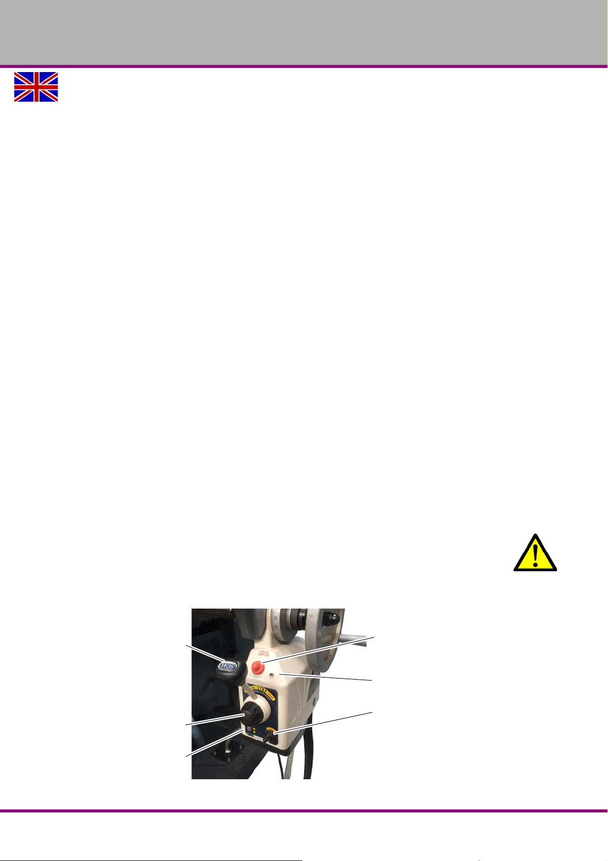
OPTIMUM
Rapid traverse
Operation control light
ON/OFF switch
Direction lever
Speed regulator
Safety switch
MASCHINEN - GERMANY
Position the milling table on desired position using the crank.
Make sure to tighten the clamping lever again once you have completed the operation.
4.11 Moving the cross table left or right
There are two ways of moving the cross table.
By turning the handwheel on the milling table.
With the automatic table feed.
4.11.1 Manual travel
To manually move the cross table, the clamping levers are released and the table is moved
with the hand crank.
Loosen the clamping levers.
Engage the hand crank by pressing into the coupling.
Position the milling table on desired position using the crank.
Clamp again if required.
4.11.2 Automatic movement of the X axis and Y axis using the feed motor
The feed motor automatically moves the cross table along the X axis and Y axis.
Turn on the ON/OFF switch.
The service light comes on.
Adjust the feed speed using the speed regulator.
Move the direction lever to the direction in which you want the cross table to move.
When the lever is in the central position, the feed motor is halted.
Do not change the motor from L to R during the operation. Wait until it has come to a com-
plete halt.
The end stop switch and th e two adjustable stops deactivate the automatic feed when the
preset position is reached.
Move the turning direction lever in the required direction.
Press the button for rapid traverse.
Once you release the button the machine will proceed at the preset speed.
WARNING!
When the feed motor is operating in fast motion, do not touch moving parts or rotating
parts.
Make sure there are no other people in the danger zone.
Img.4-3: Feed
MT50E_GB_4.fm
Operation
Version 1.0 dated 2017-05-24 Page 33Translation of the original instructions
MT50E GB
Page 34
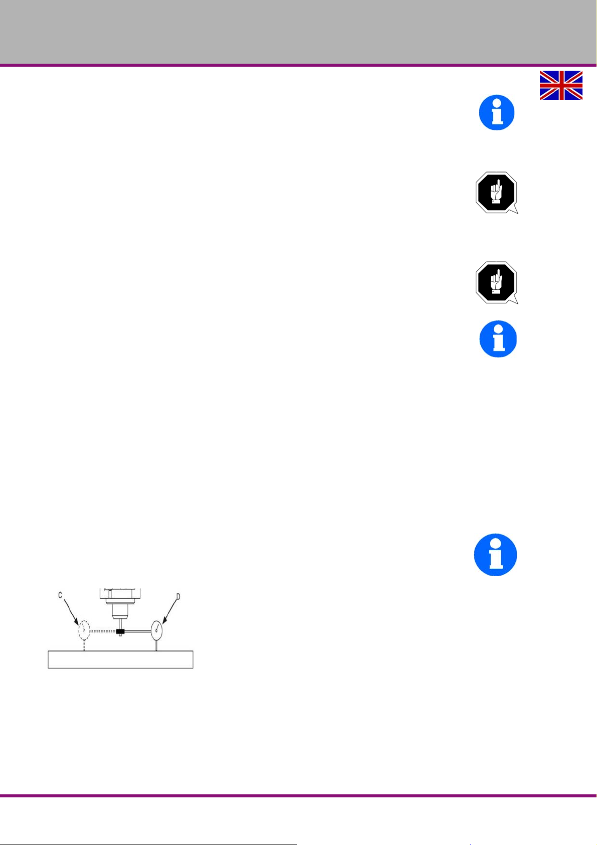
OPTIMUM
MASCHINEN - GERMANY
INFORMATION
The circuit is automatically disco nnected if a curr ent of 4 A circulates through the safety switch
for more than 10 seconds.
To reactivate it, press the safety switch for a moment.
The service light will come on again.
ATTENTION!
During manual operation the limit stops may collide with the end stop switch. This can
cause damage to the end stop switch.
4.12 Swivelling the milling head
ATTENTION!
If the milling head is slewn too far oil might escape from the gear. Therefore, we recom-
mend to slew the milling head only as far as no oil escapes while the vertical spindle is
running.
INFORMATION
The gear of the milling machine is located in open reservoirs which have to be con-
nected with the ambient air.
The milling head can be swivelled to the right and to the left.
Loosen the nuts for clamping the rotary disc maximum of one turn. A complete removal or
loosening of the nuts can lead to jamming of the rotary disc.
Rotate the square head in order to set the milling head to max. 45 °. Use the scale on the
rotary disc to set the angle.
Clamp the nuts again after adjusting the required angle.
4.12.1 Setting the milling head to zero position
Loosen the nuts to clamp the rotary disc.
Turn the square head until the milling head is in the zero position.
Retighten the nuts.
INFORMATION
The milling head should be aligned after resetting to the initial position with a dial indicator so
that holes can be produced with the spindle sleeve at a right angle.
4.13 Turning the milling head
The milling head can be swivelled to the right and to the left.
Loosen the nuts for clamping the rotary disc maximum of one turn. A complete removal or
loosening of the nuts can lead to jamming of the rotary disc.
Use the scale on the rotary disc to set the angle.
Clamp the nuts again after adjusting the required angle.
MT50E_GB_4.fm
MT50EGB
Version 1.0 dated 2017-05-24Page 34 Translation of the original instructions
Operation
Page 35
OPTIMUM
MASCHINEN - GERMANY
4.14 Turning of the cross table (X axis)
Loosen the clamping screws (4 units).
Position the milling table on desired angle position.
Imperatively fasten the clamping screws.
After completion of the work positioning the cross table back to „0“. If necessary, the cross
table must be aligned with a dial indicator again.
Make sure that the clamping screws are tightened.
4.15 Cooling
WARNING!
Discharge and overflow of cooling lubricants and lubricants Ensure that cooling
lubricants are not discharged onto the floor. Any cooling lubricants that run onto the
floor must be removed immediately.
The coolant delivery is switched on and off via a push button on the control panel.
The amount of cooling lubricant can be regulated using the dosing tap.
The friction generated during rotation can cause the edge of the tool to become very hot.
When milling it is necessary to cool down the tool depending on the material. By cooling with an
appropriate coolant lubricant you will achieve a better working result and longer durability of the
tool.
Adjust the rate of flow by means of the stop and dosing valve.
ATTENTION!
Failure of the pumps in case of dry running. The pump is lubricated by the cooling
lubricant. Do not start up the pump without cooling lubricant.
INFORMATION
Use a water-soluble environmentally friendly emulsion as cooling lubricant procured from a specialist retailer.
Respect the environment when disposing of any lubricants and cooling agents.
Follow the manufacturer’s disposal instructions.
MT50E_GB_4.fm
Operation
Version 1.0 dated 2017-05-24 Page 35Translation of the original instructions
MT50E GB
Page 36
OPTIMUM
MASCHINEN - GERMANY
5 Maintenance
In this chapter you will find important information about
Inspection
Maintenance
Repair
of the milling machine.
ATTENTION!
Properly performed regular maintenance is an essential prerequisite for
operational safety,
failure-free operation,
a long working life of the milling machine and
the quality of the products which you manufacture.
Installations and equipment from other manufacturers must also be in good order and condition.
5.1 Safety
WARNING!
The consequences of incorrect maintenance and repair work may include:
Severe injuries of persons working on the milling machine,
damage to the milling machine.
Maintenance and repair work on the milling machine must be carried out by qualified
technical personnel only.
Validation
Check and maintain all safety-relevant stop, control and measuring devices (validation).
Documentation
Record all tests and works in a operator's log resp. log book.
5.1.1 Preparation
WARNING!
Only carry out work on the milling machine, if the main switch is switched off and
secured against restarting by means of a padlock.
"Switching-off and securing the milling machine“ on page 15. Attach a warning label.
5.1.2 Restarting
Before restarting, run a safety check.
"Safety check“ on page 14
WARNING!
Before starting the milling machine, it is essential that you ensure that this does not
constitute a risk to personal safety or damage to the milling machine.
MT50EGB
Version 1.0 dated 2017-05-24Page 36 Translation of the original instructions
MT50E_GB_5.fm
Maintenance
Page 37
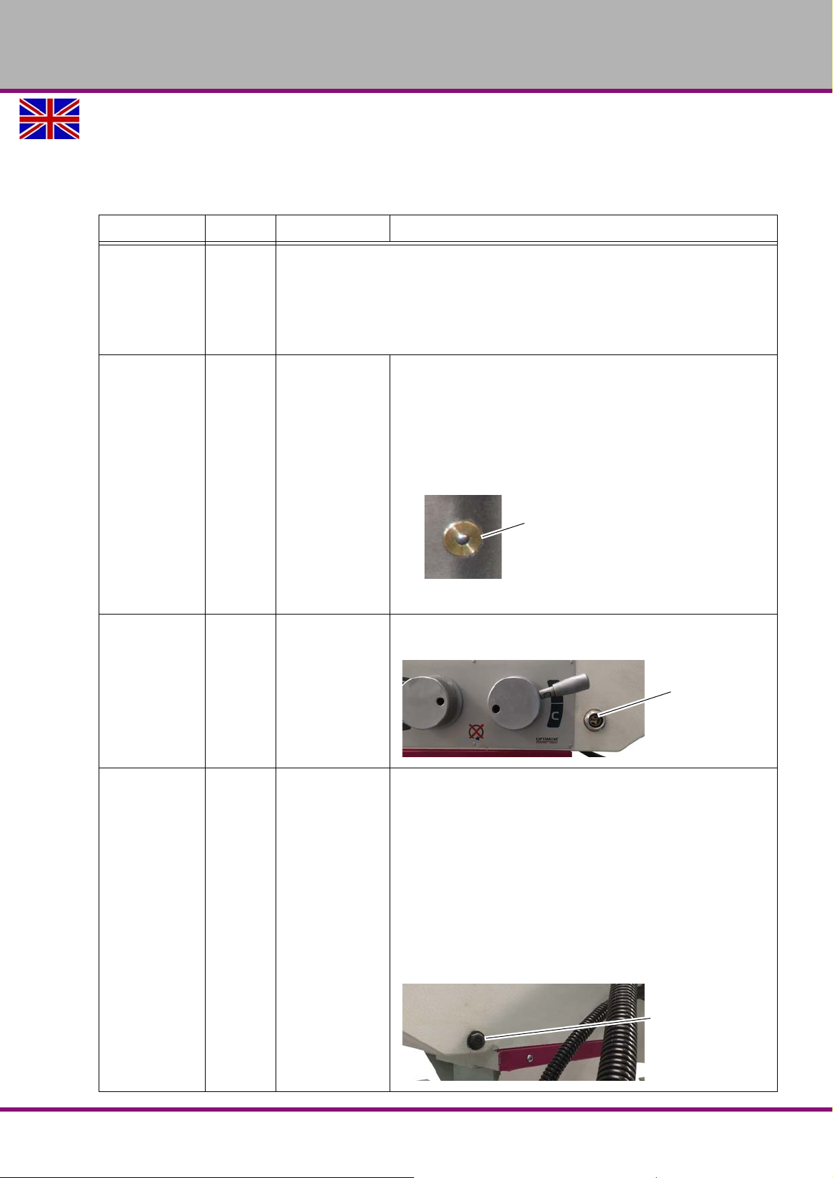
OPTIMUM
Oiler cup
Sight glass
Oil outlet
MASCHINEN - GERMANY
5.2 Inspection and maintenance
The type and level of wear depends to a large extent on the individual usage and operating
conditions. Any indicated intervals therefore are only valid for the corresponding approved conditions.
"Technical specification“ on page 18
Interval Where? What? How?
Start of work,
after every
maintenance
or repair work
Start of work,
after every
maintenance
or repair work
Monthly
"Safety check“ on page 14
Milling machine
All mobile machine parts such as guides, feed screws,
spindle nuts must be oiled in regular intervals.
Always slightly oil bare surfaces.
Lubricate the cross table lifting spindle with bearing
grease.
Oil at these lubricating point positions.
Oiling
Moving machine parts
Img.5-1: Oiler cup
The oil level must at least attain the centre resp. top
marking of the oil sight glass.
Oil level control
The first time
after 3 month,
then every
year.
MT50E_GB_5.fm
Maintenance
Spindle gear
Spindle gear
Oil change
Oil quantity about 1 litre, ISO VG68
For oil change use an appropriate collecting tray of suffi-
cient capacity.
Have the milling spindle run for a few minutes, the oil
will heat up and will slightly penetrate from the opening.
Unscrew the screw from the drain hole.
Unscrew the screw from the filler hole.
Close the drain hole if no more oil drains.
Fill up to the middle of the reference mark of the oil sight
glass into the filler hole using a suitable container.
MT50E GB
Version 1.0 dated 2017-05-24 Page 37Translation of the original instructions
Page 38
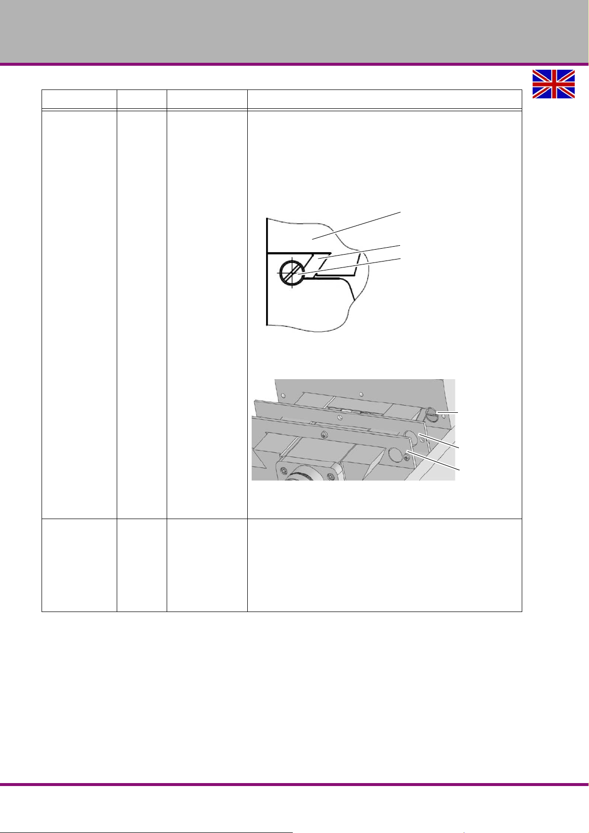
OPTIMUM
Milling table, milling head carrier, milling table, X, Y, Z
V-ledge
Adjustment screw
Adjustment
screw
Wiper
Wiper plate
MASCHINEN - GERMANY
Interval Where? What? How?
Readjust the guides by means of the corresponding V-
ledge.
If necessary disassemble the wipers in order to attain
the readjusting screws of the corresponding V-ledges.
Use a screwdriver to turn the adjusting screw clockw ise
until the movement in the respective guideway is still
easily possible.
When necessary
As required
but at least
once per year
Guideways
Coolant equipment
Readjusting
Replacing
Img.5-2: V-ledge
Dismantle the wiper plate and wiper in order to reach
the adjustment screw.
Img.5-3: Y axis V-ledge
Fill in coolant, replace if necessary.
Wash the cooling lubricant pump.
6.10 “Cooling lubricants and tanks“ on page 53
"Inspection plan for water-mixed cooling lubricants“ on
page 54
MT50EGB
MT50E_GB_5.fm
Maintenance
Version 1.0 dated 2017-05-24Page 38 Translation of the original instructions
Page 39

OPTIMUM
MASCHINEN - GERMANY
5.3 Repair
5.3.1 Customer service technician
For any repair work request the assist ance of an authorised customer service technician. Contact your specialist dealer if you do not have customer service's information or contact Stürmer
Maschinen GmbH in Germany who can provide you with a specialist dealer's contact information. Optionally, the company Stürmer Maschinen GmbH
Dr.-Robert-Pfleger-Str. 26
D- 96103 Hallstadt
can provide a customer service technician, however, the request for a customer service techni-
cian can only be made via your specialist dealer.
If the repairs are carried out by qualified technical personnel, they must follow the indications
given in these operating instructions.
Optimum Maschinen Germany GmbH accepts no liability nor does it guarantee against damage
and operating malfunctions resulting from failure to observe these operating instructions.
For repairs, only use
faultless and suitable tools only,
original parts or parts from series expressly authorised by Optimum Maschinen Germany
GmbH.
MT50E_GB_5.fm
Maintenance
Version 1.0 dated 2017-05-24 Page 39Translation of the original instructions
MT50E GB
Page 40
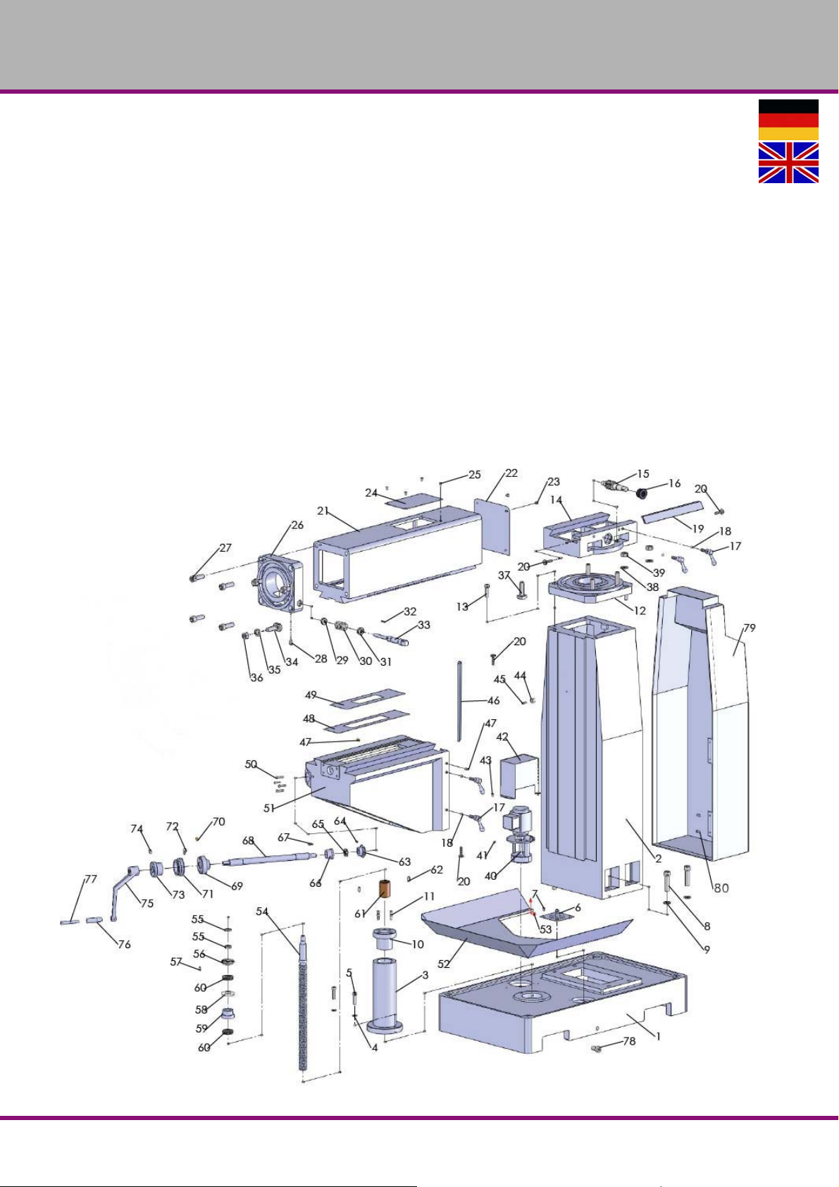
OPTIMUM
MASCHINEN - GERMANY
6 Ersatzteile - Spare parts - MT50E
6.1 Ersatzteilbestellung - Ordering spare parts
Bitte geben Sie folgendes an - Please indicate the following :
Seriennummer - Serial No.
Maschinenbezeichnung - Machines name
Herstellungsdatum - Date of manufacture
Artikelnummer - Item no.
Die Artikelnummer befindet sich in der Ersatzteilliste. The article no. is located in the spare part
list. Die Seriennummer befindet sich am Typschild. The serial no. is is on the type plate.
6.2 Schaltplan - Wiring diagram
Der aktuelle Schaltplan befindet sich im Schaltschrank der Maschine. The current circuit
diagram is located in the control cabinet of the machine.
6.3 Maschinenfuß und Säule - Base & Column
6-1: Base & Column
MT50EDE | GB
MT50E_parts.fm
Version 1.0 2017-5-24 40 Originalbetriebsanleitung
Page 41
OPTIMUM
MASCHINEN - GERMANY
Ersatzteilliste Maschinenfuß und Säule - Base & Column part list
Bezeichnung Designation
Pos.
1 Grundplatte Base 1 033360100101
2 Säule Column 1 033360100102
3 Gehäuse Hebeschraube Elevating Screw Housing 1 033360100103
4 Sicherungsscheibe Lock Washer 2 10mm
5 Sechskantschraube Hex Bolt 2 M10 x 45
6 Anschlussschlauch Connect Tube 1 033360100106
7 Kreuzschlitzschraube Phlp Hd Scr. 4 M6 x 12
8 Sechskantschraube Hex Bolt 4 M16 x 25
9 Sicherungsscheibe Lock Washer 4 16mm
10 Manschette Collar 1 033360100110
11 Innensechskantschraube Cap Screw 2 M8 x 25
12 Haltestütze Hold Support 1 033360100112
13 Innensechskantschraube Cap Screw 4 M12 x 30
14 Runde Halterung Around Bracket 1 033360100114
15 Vorschubwelle Feed Shaft 1 033360100115
16 Manschette Collar 1 033360100116
17 Klemmschraube Clamp Bolt 4 M10 x 53 x 25 033360100117
18 Klemmblock Clamp Block 4 033360100118
19 Leiste Gib 1 033360100119
20 Flachkopfschraube Flat Hd Scr. 4 M8 x 40
21 Gegenhalter Overarm 1 033360100121
22 Abdeckung Cover 1 033360100122
23 Kreuzschlitzschraube Phlp Hd Scr. 4 M6 x 10
24 Abdeckung Cover 1 033360100124
25 Kreuzschlitzschraube Phlp Hd Scr. 4 M6 x 10
26 Halteklammer Hold Bracket 1 033360100126
27 Innensechskantschraube Cap Screw 4 M16 x 50
28 Innensechskantschraube Cap Screw 1 M8 x 20
29 Kugellager Ball Bearing 1 51101 04051101
30 Schnecke Worm 1 033360100130
31 Kugellager Ball Bearing 1 51102 04051102
32 Passfeder Key 1 4 x 4 x 20
33 Schneckenwelle Worm Shaft 1 033360100133
34 T-Schraube T Bolt 3 M16 x 60
35 Unterlegscheibe Washer 3 16mm
36 Sechskantmutter Hex Nut 3 M16
37 T-Schraube T Bolt 4 M16 x 50
38 Unterlegscheibe Washer 4 16mm
39 Sechskantmutter Hex Nut 4 M16
40 Elektrische Pumpe Electric Pump 1 033360100140
41 Innensechskantschraube Cap Screw 4 M5 x 12
42 Schild Shield 1 033360100142
43 Innensechskantschraube Cap Screw 2 M5 x 12
44 H ülse Sleeve 1 033360100144
45 Schraube Screw 1 M6 x 18
46 Leiste Gib 1 033360100146
47 Öl-Schale Billiard Oil Cup 4 033360100147
48 Abstreiferplatte Wiper Plate 1 033360100148
49 Abstreiferplatte Wiper Plate 1 033360100149
50 Innensechskantschraube Cap Screw 4 M6 x 25
51 Tischträger Knee 1 033360100151
52 Ölwanne Oil Pan 1 033360100152
53 Innensechskantschraube Cap Screw 2 M6 x 12
54 Hubspindel Tisch Hoist Descend Lead Screw 1 033360100154
55 Rundmutter Circular Nut 2 M16 x 1.5 033360100155
56 Kegelzahnrad Conical Gear 1 033360100156
57 Passfeder Key 1 6 x 6 x 12
58 Einstellscheibe Adjust Washer 1 033360100158
59 Manschette Collar 1 033360100159
60 Kugellager Ball Bearing 2 51105 04051105
61 Mutter Nut 1 42 x 60mm 033360100161
62 Stiftschra ube Set Screw 2 M8 x 20
63 Kegelzahnrad Conical Gear 1 033360100163
64 Stiftschra ube Set Screw 1 M6 x 10
65 Kugellager Ball Bearing 1 51103 04051103
66 Manschette Collar 1 033360100166
67 Passfeder Key 1 5 x 5 x 20
68 Welle Shaft 1 033360100168
69 Manschette Collar 1 033360100169
70 Innensechskantschraube Cap Screw 1 M6 x 22 0
71 Skalenring Scale Ring 1 033360100171
72 Rändelschraube Knurled Thumb Scr. 1 M6 x 10
MT50E_parts.fm
Menge Grösse Artikelnummer
Qty. Size Item no.
Version 1.0 2017-5-24 41Originalbetriebsanleitung
MT50E DE | GB
Page 42
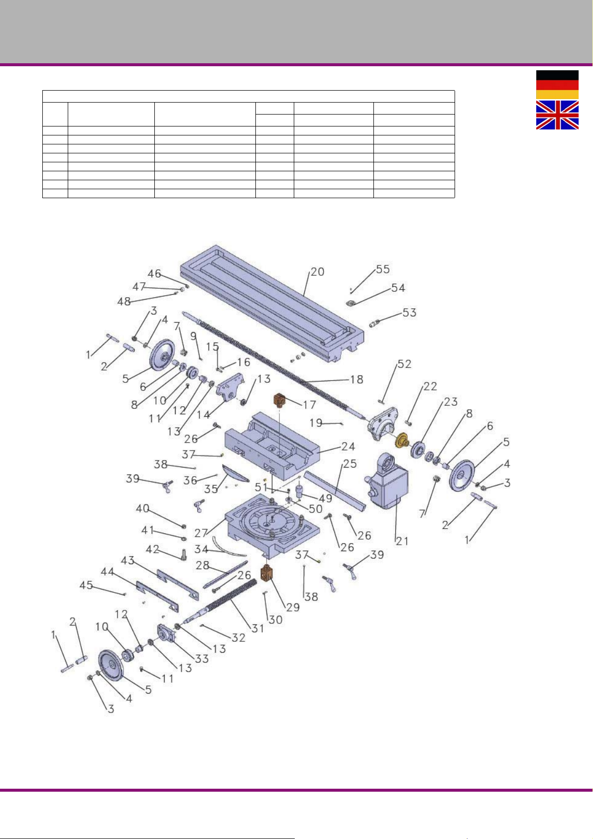
OPTIMUM
MASCHINEN - GERMANY
Ersatzteilliste Maschinenfuß und Säule - Base & Column part list
Bezeichnung Designation
Pos.
73 Manschette Collar 1 033360100173
74 Stiftschraube Set Screw 1 033360100174
75 Griff Handle 1 033360100175
76 Kegelknopf Taper Knob 1 033360100176
77 Griffwelle Handle Spindle 1 033360100177
78 Schraube Screw 1 033360100178
79 Hintere Abdeckung Behind Cover 1 033360100179
80 Flachkopfschraube Flat Hd Scr. 4 M5 x 12
6.4 Frästisch - Milling table
Menge Grösse Artikelnummer
Qty. Size Item no.
6-2: Milling table
MT50EDE | GB
MT50E_parts.fm
Version 1.0 2017-5-24 42 Originalbetriebsanleitung
Page 43
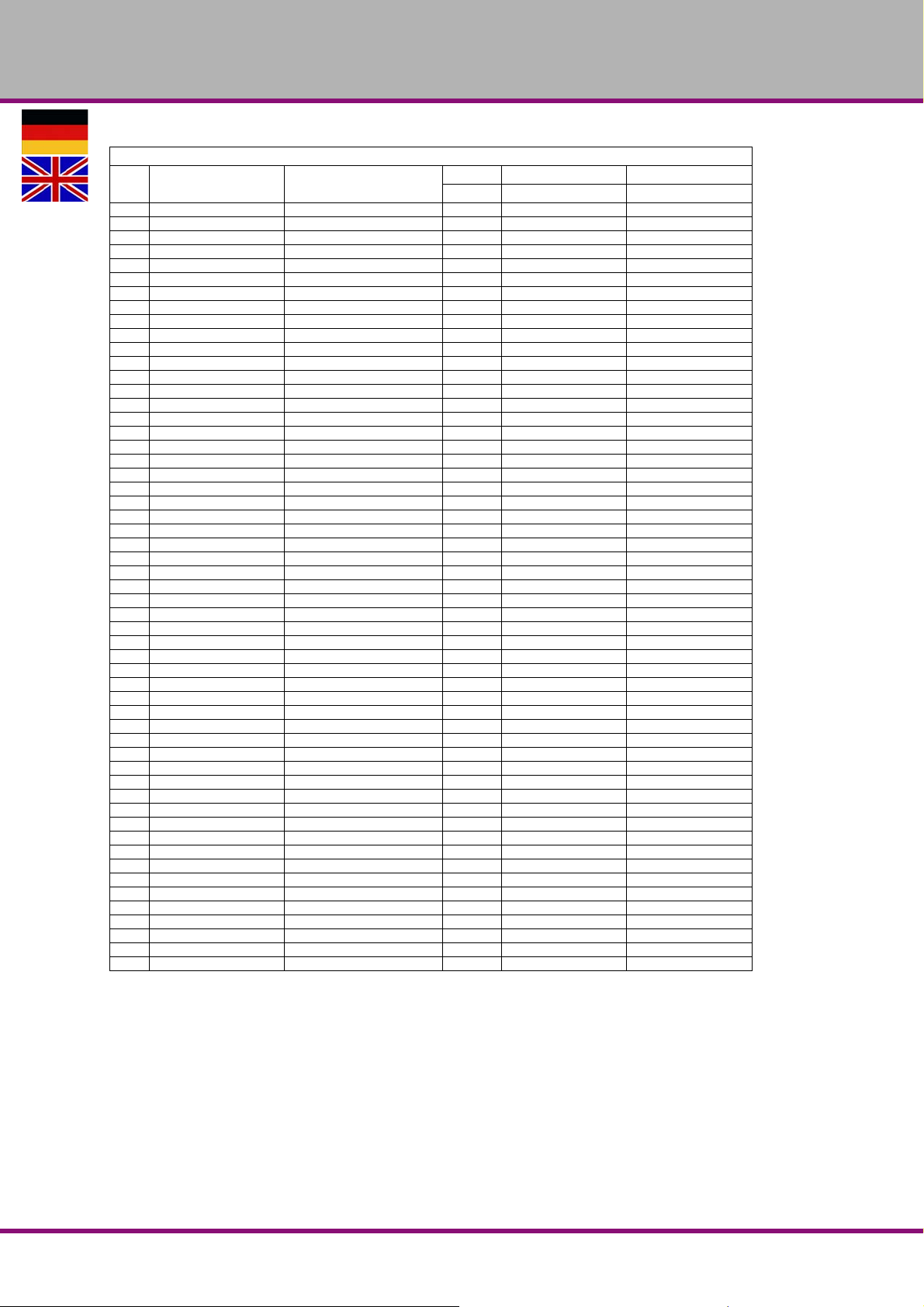
OPTIMUM
MASCHINEN - GERMANY
Ersatzteilliste Frästisch- Milling table
Bezeichnung Designation
Pos.
1 Griffwelle Handle Spindle 3 033360100201
2 Kegelknopf Taper Knob 3 033360100202
3 Sechskantmutter Hex Nut 3 M12
4 Sicherungsscheibe Lock Washer 3 12mm
5 Handrad Hand Wheel 3 033360100205
6 Buchse Bush 2 033360100206
7 Feder Spring 2 033360100207
8 Anschluss Connect 2 033360100208
9 Passfeder Key 1 5X20
10 Skalenring Scale Ring 2 033360100210
11 Innensechskantschraube Cap Screw 2 M6 x 16
12 Manschette Collar 2 033360100212
13 Kugellager Ball Bearing 4 51103 04051103
14 Halterung Support 1 033360100214
15 Innensechskantschraube Cap Screw 6 M8 x 25
16 Stift Pin 2 6 x 25 033360100216
17 Spezialmutter Special Nut 1 033360100217
18 Lange Leitspindel Long Lead Screw 1 033360100218
19 Passfeder Key 1 5 x 20
20 Tisch Table 1 033360100220
21 Vorschub Antrieb Power Feed 1 033360100221
22 Innensechskantschraube Cap Screw 4 M10 x 25
23 Skalenring Scale Ring 1 033360100223
24 Drehbare Halterung Rotary Bracket 1 033360100224
25 Leiste Gib 1 033360100225
26 Einstellschraube Adjust Screw 3 M8 033360100226
27 Mittelbasis Center Base 1 033360100227
28 Leiste Gib 1 033360100228
29 Spezialmutter Special Nut 1 033360100229
30 Schraube Screw 3 M5 x 25
31 Lange Leitspindel Long Lead Screw 1 033360100231
32 Passfeder Key 1 5 x 30
33 Halterung Support 1 033360100233
34 Winkel, Lineal Angle Ruler 1 033360100234
35 Schutz Guard 1 033360100235
36 Schraube Screw 2 M5 x 10
37 Öler Oil Cup 4 8 033360100237
38 Klemmblock Clamp Block 4 033360100238
39 Klemmschraube Clamp Bolt 4 M10 x 53 x 25 033360100239
40 Sechskantmutter Hex Nut 4 M12
41 Unterlegscheibe Washer 4 12
42 T-Schraube T Bolt 4 M12 x 42
43 Abstreiferplatte Wiper Plate 1 033360100243
44 Bahn Abdeckung Way Cover 1 033360100244
45 Kreuzschlitzschraube Phlp Hd Scr. 3 M5 x 12
46 Schra ube der Halterung Screw Bracket 1 033360100246
47 Anschlag Dog 1 033360100247
48 Innensechskantschraube Cap Screw 1 M6 x 16
49 Welle Shaft 1 033360100249
50 Unterlegscheibe Washer 1 033360100250
51 Schraube Screw 1 M6 x 30
52 Stift Pin 2 6 x 25 033360100252
53 Anschlussschlauch Connect Tube 1 033360100253
54 Spritzschutz Splash Guard 1 033360100254
55 Schraube Screw 2 M4 x 8
Menge Grösse Artikelnummer
Qty. Size Item no.
MT50E_parts.fm
Version 1.0 2017-5-24 43Originalbetriebsanleitung
MT50E DE | GB
Page 44
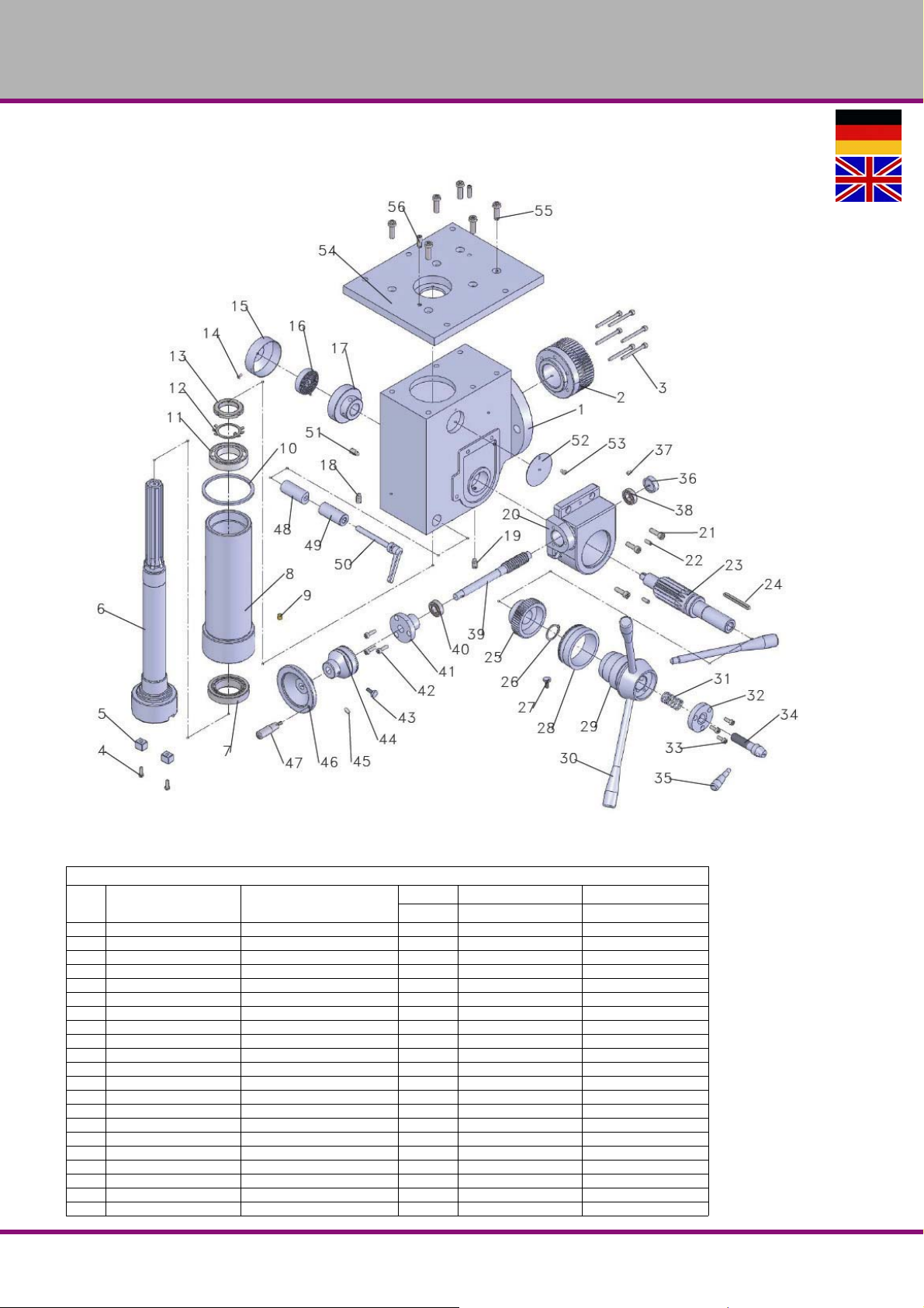
OPTIMUM
MASCHINEN - GERMANY
6.5 Fräskopf - Milling head
6-3: Milling head
Ersatzteilliste Fräskopf - Milling head part list
Bezeichnung Designation
Pos.
1 Spindelkasten Spindle Box 1 033360100301
2 Zahnrad Gear 1 033360100302
3 Schraube Screw 6 M6 x 75
4 Schraube Screw 2 M6 x 16
5 Feste Passfeder Fixed Key 2 033360100305
6 Spindel Spindle 1 033360100306
7 Kugellager Ball Bearing 1 32010 04032010
8 Hülse Sleeve 1 033360100308
9 Öler Oil Cup 1 033360100309
10 Gummischeibe Rubber Washer 1 90mm 033360100310
11 Kugellager Ball Bearing 1 6009 0406009
12 Sicherungsscheibe Lock Washer 1 40 033360100312
13 Sicherungsmutter Lock Nut 1 M40 x 1.5 033360100313
14 Innensechskantschraube Cap Screw 1 M4 x 8
15 Federteller Spring Cap 1 033360100315
16 Federplatte Spring Plate 1 033360100316
17 Federgehäuse Spring Base 1 033360100317
18 Stiftschraube Set Screw 1 M8 x 16
19 Stiftschraube Set Screw 1 M8 x 16
20 Handrad Getriebe Handl Wheel Gear Box 1 03 3360100320
21 Schraube Screw 3 M8 x 25
MT50EDE | GB
Menge Grösse Artikelnummer
Qty. Size Item no.
MT50E_parts.fm
Version 1.0 2017-5-24 44 Originalbetriebsanleitung
Page 45
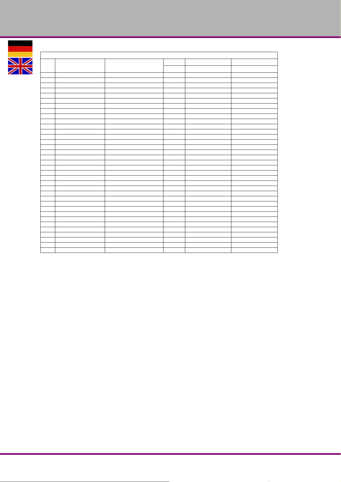
OPTIMUM
MASCHINEN - GERMANY
Ersatzteilliste Fräskopf - Milling head part list
Bezeichnung Designation
Pos.
22 Stift Pin 2 6 x 25 033360100322
23 Vorschubwelle Feed Shaft 1 033360100323
24 Passfeder Key 1 8 x 38
25 Stirnradgetriebe Helical Gear 1 033360100325
26 Sicherungsring Ex Retaining Ring 1 30 033360100326
27 Innensechskantschraube Cap Screw 1 M6 x 16
28 Skalenring Scale Ring 1 033360100328
29 Nabe Handgriff Handle Bracket Hub 1 033360100329
30 Griffstange Handle Bar 2 033360100330
31 Druckfeder Compression Spring 1 033360100331
32 Abdeckung Cover 1 033360100332
33 Innensechskantschraube Cap Screw 3 M6 x 16
34 Griff Sitz Handle Seat 1 M16 x 2 033360100334
35 Griffstange Handle Bar 1 033360100335
36 Abdeckung Cover 1 033360100336
37 Schraube Screw 1 M6 x 12
38 Kugellager Ball Bearing 1 6002 0406002
39 Schnecke Worm 1 033360100339
40 Kugellager Ball Bearing 1 6002 0406002
41 Abdeckung Cover 1 033360100341
42 Schraube Screw 3 M6 x 20 033360100342
43 Innensechskantschraube Cap Screw 1 M6 x 16
44 Skalenring Scale Ring 1 033360100344
45 Schraube Screw 1 M6 x 12 033360100345
46 Handrad H andle Wheel 1 033360100346
47 Griff Handle 1 033360100347
48 Klemmblock Clamp Block 1 033360100348
49 Klemmblock Clamp Block 1 033360100349
50 Klemmgriff Clamp Handle 1 033360100350
51 Stiftschraube Set Screw 2 M10 x 10
52 Leitblech Baffle 1 033360100352
53 Schraube Screw 1 M5 x 10 033360100353
54 Getriebeabdeckung Head Box Cover 1 033360100354
55 Schraube Screw 6 M10 x 30 033360100355
56 Stift Pin 2 8 x 25 033360100356
Menge Grösse Artikelnummer
Qty. Size Item no.
MT50E_parts.fm
Version 1.0 2017-5-24 45Originalbetriebsanleitung
MT50E DE | GB
Page 46
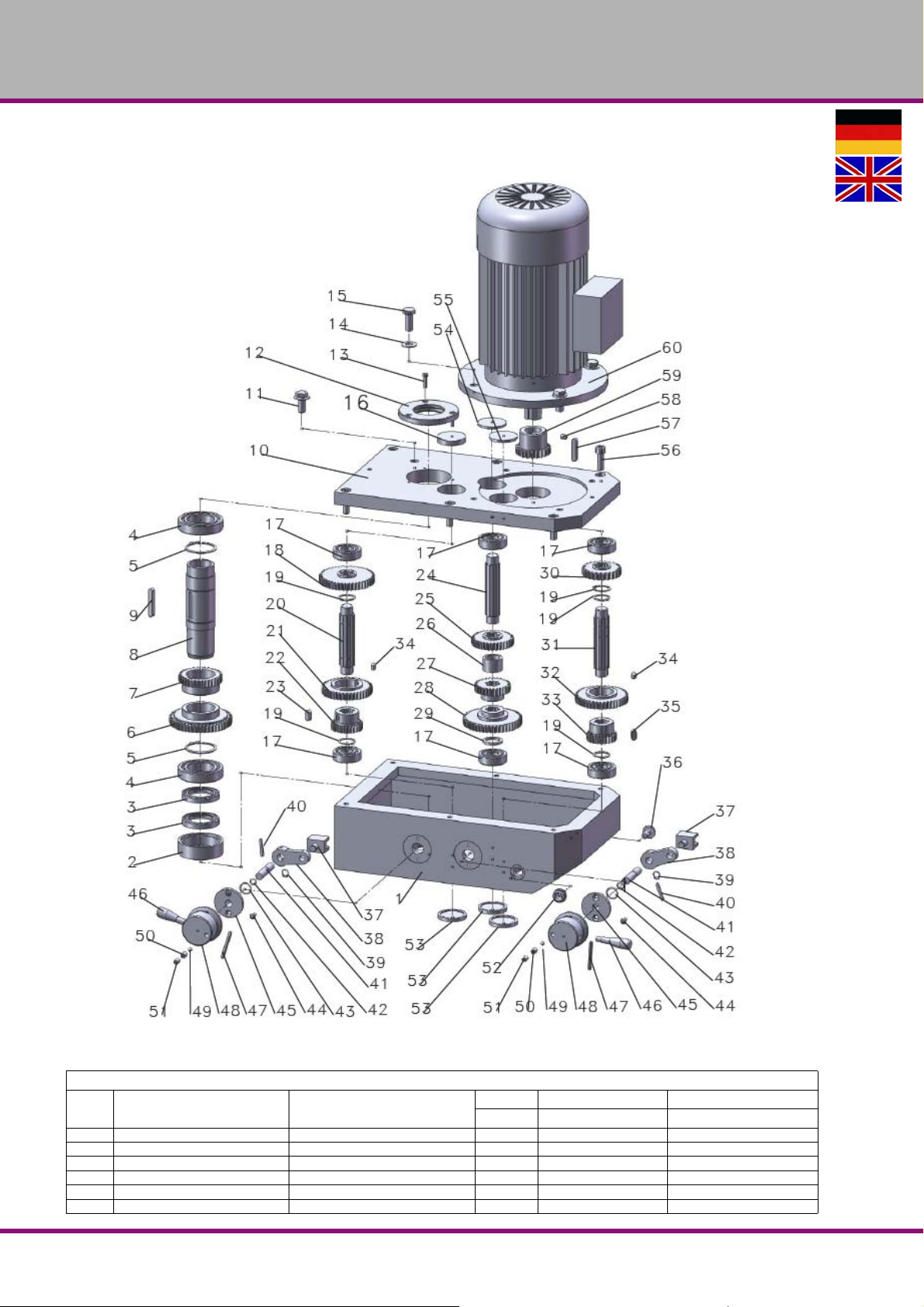
OPTIMUM
MASCHINEN - GERMANY
6.6 Getriebe Fräskopf - Milling head gear
6-4: Milling head gear
Getriebe Fräskopf - Milling head gear
Pos.
Bezeichnung Designation
1 Getriebekasten Gear Case 1 033360100401
2 Manschette Collar 1 033360100402
3 Öldichtung Oil Seal 2 Fb45 x 62 x 8 033360100403
4 Kugellager Ball Bearing 2 6009 0406009
5 Sicherungsring Ex Retaining Ring 2 48 033360100405
6 Zahnrad Gear 1 033360100406
MT50EDE | GB
Menge Grösse Artikelnummer
Qty. Size Item no.
Version 1.0 2017-5-24 46 Originalbetriebsanleitung
MT50E_parts.fm
Page 47
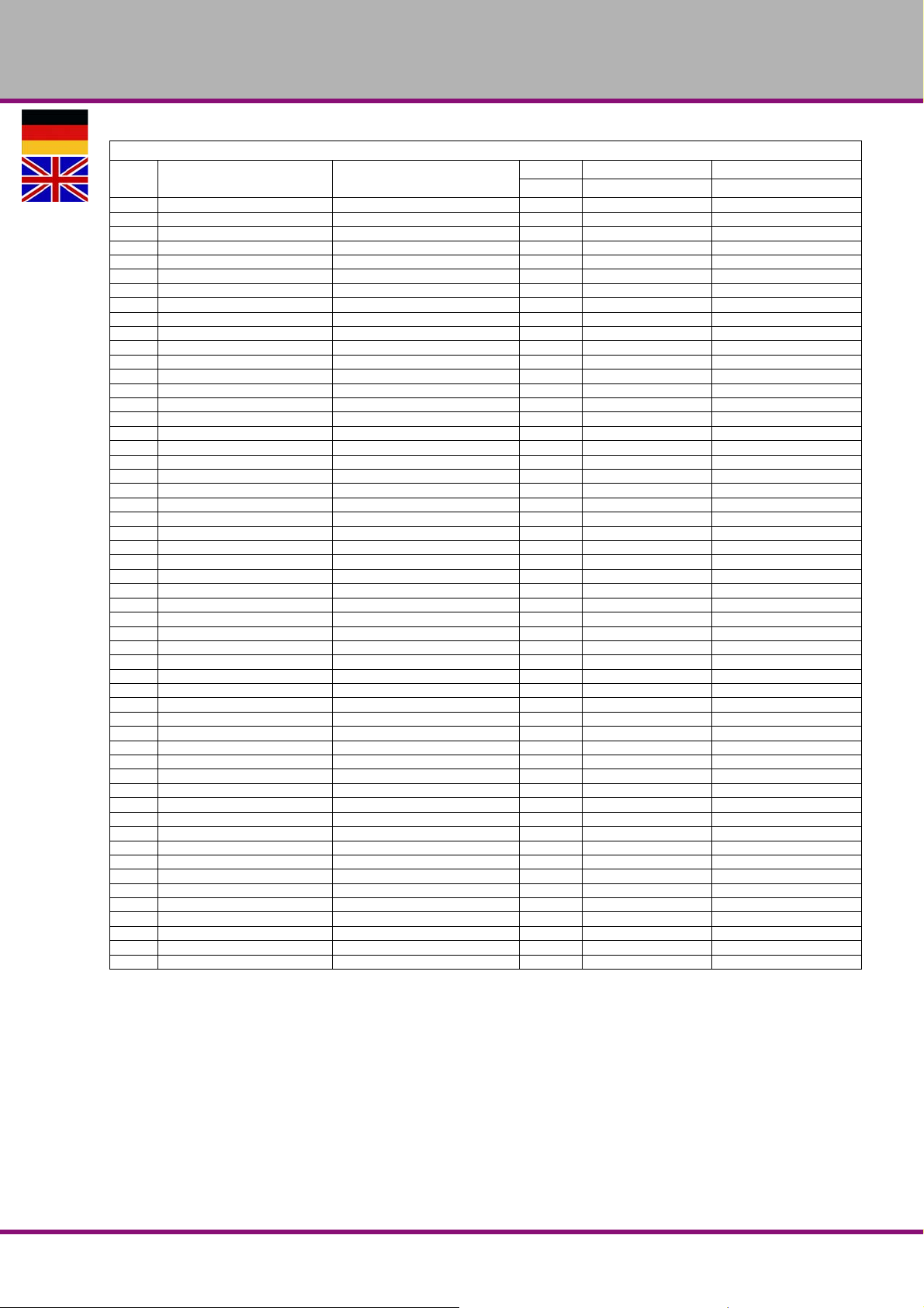
OPTIMUM
MASCHINEN - GERMANY
Getriebe Fräskopf - Milling head gear
Pos.
Bezeichnung Designation
7 Zahnrad Gear 1 033360100407
8 Welle Shaft 1 033360100408
9 Passfeder Key 1 8 x 50
10 Gehäusedeckel Box Cover 1 033360100410
11 Sechskantschraube Hex Bolt 1 M16 x 1.5 033360100411
12 Manschette Collar 1 033360100412
13 Schraube Screw 3 M5 x 15 033360100413
14 Unterlegscheibe Washer 4 12
15 Schraube Screw 4 033360100415
16 Abdeckung Cover 1 033360100416
17 Kugellager Ball Bearing 6 6204 0406204
18 Zahnrad Gear 1 033360100418
19 Sicherungsring Ex Retaining Ring 5 25 033360100419
20 Antriebswelle Driving Shaft 1 033360100420
21 Zahnrad Gear 1 033360100421
22 Zahnrad Gear 1 033360100422
23 Passfeder Key 1 8 x 15
24 Antriebswelle Driving Shaft 1 033360100424
25 Zahnrad Gear 1 033360100425
26 Buchse Bush 1 033360100426
27 Zahnrad Gear 1 033360100427
28 Zahnrad Gear 1 033360100428
29 Ring Ring 1 033360100429
30 Zahnrad Gear 1 033360100430
31 Antriebswelle Driving Shaft 1 033360100431
32 Zahnrad Gear 1 033360100432
33 Zahnrad Gear 1 033360100433
34 Stiftschraube Set Screw 4 M8 x 10
35 Passfeder Key 1 8 x 15
36 Sechskantschraube Hex Bolt 1 M10 x 1
37 Hebegabel Lift Fork 2 033360100437
38 Kipphebel Rocker Arm 2 033360100438
39 Sicherungsring Ex Retaining Ring 2 10 033360100439
40 Stift Pin 2 5 x 30 033360100440
41 Kleine Spindel Small Spindle 2 033360100441
42 Gummiring Rubber Ring 2 12 x 2 033360100442
43 Gummiring Rubber Ring 2 20 x 2 033360100443
44 Schraube Screw 4 5 x 12 033360100444
45 Abdeckung Cover 2 033360100445
46 Griff Handle 2 033360100446
47 Stift Pin 2 5 x 50 033360100447
48 Griff Sitz Handle Seat 2 033360100448
49 Stahlkugel Steel Ball 2 6 033360100449
50 Feder Spring 3 033360100450
51 Stiftschraube Set Screw 2 033360100451
52 Öl Zeiger Oil Pointer 1 033360100452
53 Abdeckung Cover 3 033360100453
54 Abdeckung Cover 1 033360100454
55 Abdeckung Cover 1 033360100455
56 Schraube Screw 4 M10 x 30 033360100456
57 Passfeder Key 1 8 x 40
58 Stiftschraube Set Screw 1 M8 x 10
59 Zahnrad Gear 1 033360100459
60 Motor Motor 1 033360100460
Menge Grösse Artikelnummer
Qty. Size Item no.
MT50E_parts.fm
Version 1.0 2017-5-24 47Originalbetriebsanleitung
MT50E DE | GB
Page 48
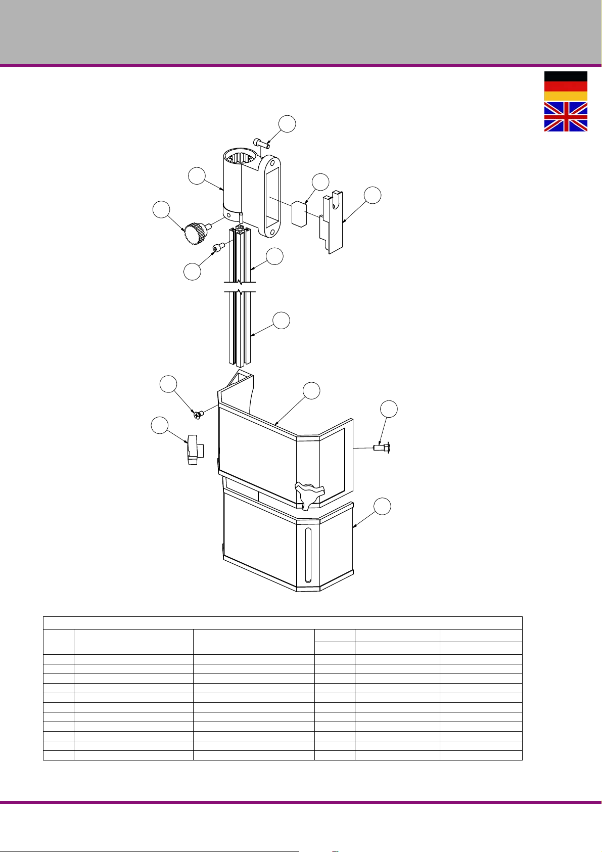
OPTIMUM
1
2
3
4
5
5
6
6
7
8
9
14
15
MASCHINEN - GERMANY
6.7 Fräsfutterschutz - Milling chuck cover
Abb.6-5: Fräsfutterschutz - Milling chuck cover
Teileliste Fräsfutterschutz - Parts list milling chuck cover
Bezeichnung Description
Pos.
1 Rändelschraube Knurled screw 1 0333609007 033360100501
2 Halterung Fixture 1 033360100502
3 Mikroschalter Microswitch 1 033360100503
4 Platte Plate 1 033360100504
5 Alu- Profil Aluminium profile 1 033360100505
6 Schraube Screw 2 M5x10
7 Fräsfutterschutz A Mill chuck cover A 1 033360100507
8 Fräsfutterschutz B Mill chuck cover B 1 033360100508
9 Schraube Screw 2 M5x10
14 Rändelmutter Knurled nut 2 033360100514
15 Klemmschraube Clamping screw 2 033360100515
Menge Grösse Artikelnummer
Qty. Size Item no.
MT50E_parts.fm
MT50EDE | GB
Version 1.0 2017-5-24 48 Originalbetriebsanleitung
Page 49
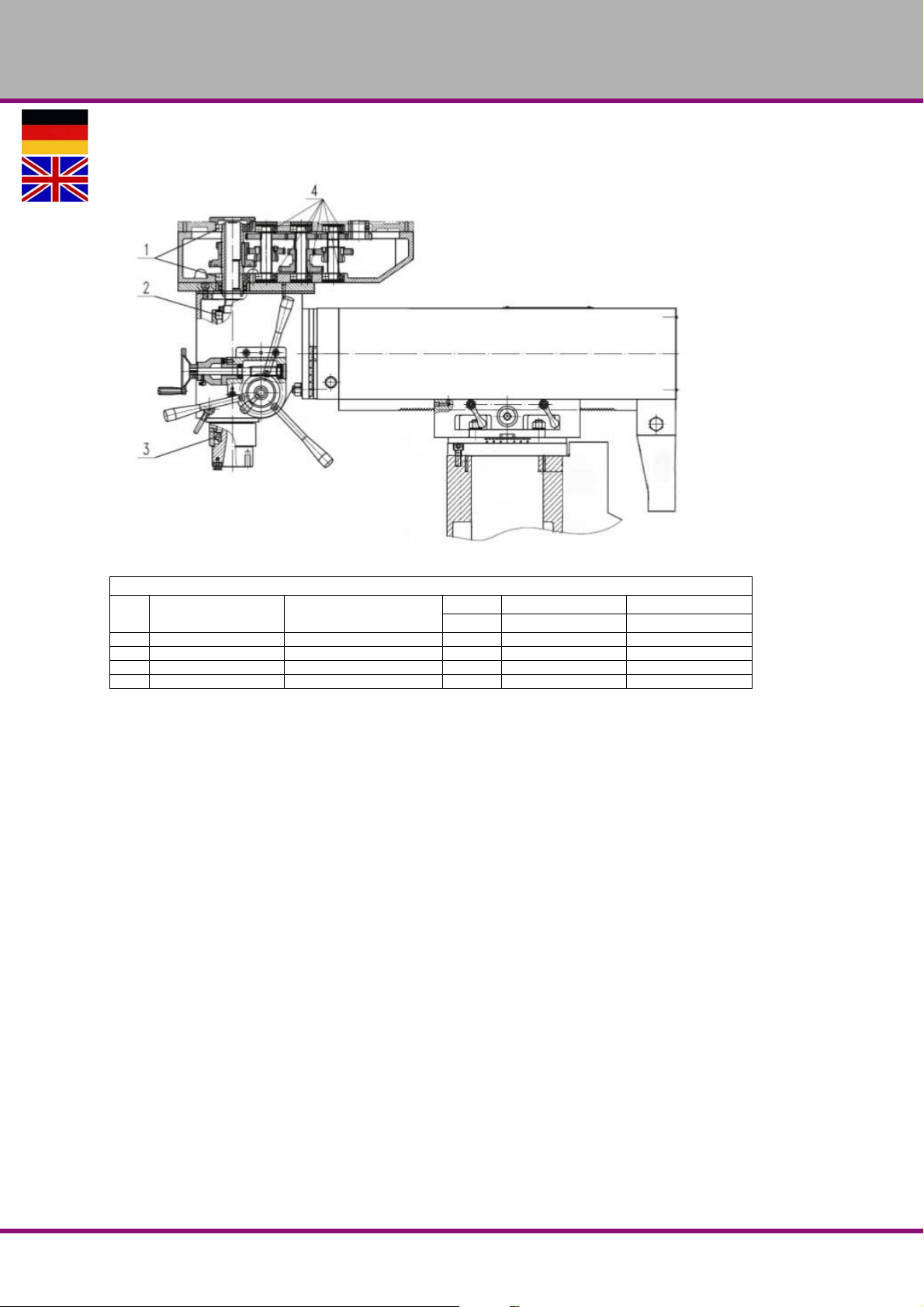
6.8 Lagerübersicht - Bearing overview
OPTIMUM
MASCHINEN - GERMANY
Ersatzteilliste Lager - Bearing part list
Bezeichnung Designation
Pos.
1 Lager Bearing 6009 / P5 0406009
2 Lager Bearing 6009 / P5 0406009
3 Lager Bearing 32010 / P5 04032010
4 Lager Bearing 6204 / P5 0406204
Menge Grösse Artikelnummer
Qty. Size Item no.
MT50E_parts.fm
Version 1.0 2017-5-24 49Originalbetriebsanleitung
MT50E DE | GB
Page 50
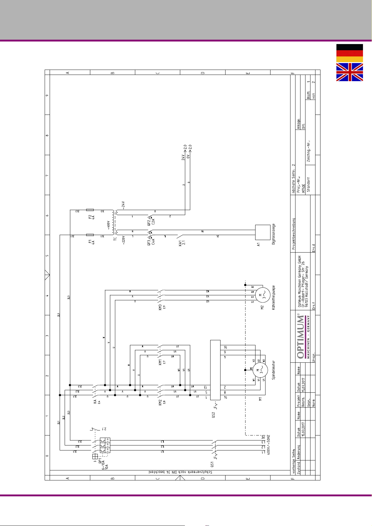
OPTIMUM
MASCHINEN - GERMANY
6.9 Schaltplan - Wiring diagram
MT50E_parts.fm
MT50EDE | GB
Version 1.0 2017-5-24 50 Originalbetriebsanleitung
Page 51
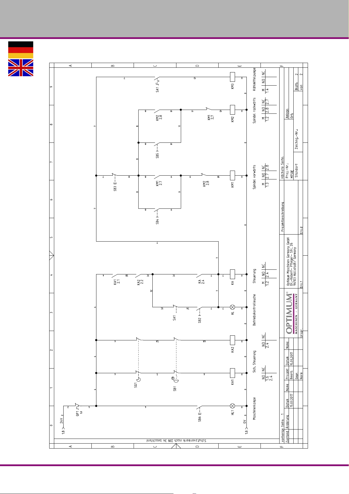
OPTIMUM
MASCHINEN - GERMANY
MT50E_parts.fm
Version 1.0 2017-5-24 51Originalbetriebsanleitung
MT50E DE | GB
Page 52
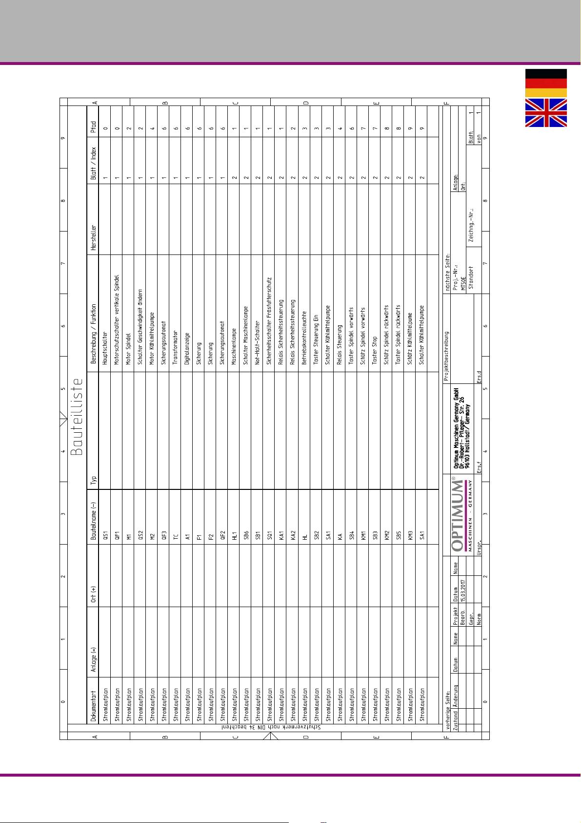
OPTIMUM
MASCHINEN - GERMANY
MT50E_parts.fm
MT50EDE | GB
Version 1.0 2017-5-24 52 Originalbetriebsanleitung
Page 53
OPTIMUM
MASCHINEN - GERMANY
6.10 Cooling lubricants and tanks
CAUTION!
The cooling lubricant can cause diseases. Avoid direct contact with cooling lubricant or
parts covered in cooling lubricant.
Cooling lubricant circuits and tanks for water-cooling lubricant mixtures must be completely
emptied, cleaned and disinfected as needed, but at least once per year or every time the cooling lubricant is replaced.
If fine chips and other foreign matters are ac cumulated in the coolant tank, the machine can no
longer be correctly supplied with coolant. Furthermore, the lifetime of the coolant pump is
reduced.
When processing cast iron or similar materials generating fine chips, cleaning the coolant tank
more often is recommended.
Limit values
The cooling lubricant must be replaced, the cooling lubricant circuit and tank emptied,
cleaned and disinfected if
the pH value drops by more than 1 based on the value during initial filling. The maximum
permissible pH value during initial filing is 9.3
there is a perceivable change in the appearance, odour, floating oil or increase of the bacte-
ria to more than 10/6/ml
there is an increase in nitrite content to more than 20 ppm (mg/1) or nitrate content to more
than 50 ppm (mg/1)
there is an increase in the N-nitrosodiethanolamine (NDELA) to more than 5 ppm (mg/a)
CAUTION!
Comply with the manufacturer's specifications for mixture ratios, hazardous substances,
e.g. system cleaners, including their permissible minimum use times.
CAUTION!
Since the cooling lubricant escapes under high pressure, pumping out the coolant by
using the existing cooling lubricant pump via a pressure hose into a suitable tank is not
recommended.
ENVIRONMENTAL PROTECTION
During work on the cooling lubricant equipment please make sure that
collector tanks are used with sufficient capacity for the amount of liquid to be col-
lected.
liquids and oils should not be spilled on the ground.
Clean up any spilled liquid or oils immediately using proper oil-absorption methods and dispose of them in accordance with current statutory environmental regulations.
Collect leakages
Do not re-introduce liquids spilled outside the system during repair or as a result of leakage
from the reserve tank, instead collect them in a collecting container for disposal.
Disposal
Never dump oil or other substances which are harmful to the environment into water inlets, rivers or channels. Used oils must be delivered to a collection centre. Consult your supervisor if
you do not know where the collection centre is.
coolant_GB.fm
Version 1.0 dated 2017-05-24 Page 53Original operating instructions
Coolant lubricating EN
Page 54

OPTIMUM
MASCHINEN - GERMANY
6.10.1 Inspection plan for water-mixed cooling lubricants
Company:
No.:
Date:
used cooling lubricant
size to be checked Inspection methods Inspection
intervals
noticeable
changes
pH value Laboratory techniques
Usage concentration Manual refractometer
Base reserve Acid titration in accordance
Nitrite content Test sticks method or labora-
Nitrate/nitrite content
of the preparation water, if
this is not removed from
the public
grid
Appearance, odour daily Find and rectify causes,
1)
electrometric with pH meter
(DIN 51369)
Local measurement method:
with pH paper
(Special indicators with
suitable measuring range)
with
Manufacturer's recommendation
tory method
Test sticks method or laboratory method
weekly
1)
weekly
as required Method is independent of tramp oil content
1)
weekly
as required Use water from the public grid if there is
Procedure and comment
e.g. skim off oil, check filter, ventilate cooling
lubricant system
if pH value decreases
> 0.5 based on initial filing:
Measures in accordance manufacturer's recommendations
> 1.0 based on initial filing:
Replace cooling lubricant, clean cooling lubricant circulation system
Method results in incorrect values with tramp
oil content
> 20 mg/L nitrite:
Replace cooling lubricant or part
or inhibiting additives;
otherwise NDELA (N-nitrosodiethanolamine)
in the cooling lubricant system and in the air
must be determined
> 5 mg/L NDELA in the cooling lubricant system:
Replacement,
clean and disinfect cooling lubricant circulation system, find nitrite source and, if possible, rectify.
water from the pubic grid has
> 50 mg/l nitrate: Inform the waterworks
1)
The specified inspection intervals (frequency) are based on continuous operation. Other operational
conditions can result in other inspection intervals; exceptions are possible in accordance with Sections 4.4
and 4.10 of the TGS 611.
Editor:
Signature:
Coolant lubricatingEN
Version 1.0 dated 2017-05-24Page 54 Original operating instructions
coolant_GB.fm
Page 55
Version 1.0 2017-05-24 Seite 55Translation of the original instructions
oil-compare-list.fm
Schmierstoffe
Lubricant
Lubrifiant
Viskosität
Viskosity
Viscosité ISO VG
DIN 51519 mm²/s
(cSt)
VG 680 CLP 680
VG 460 CLP 460
Kennzeich-
nung nach
DIN 51502
Aral Degol BG
680
Aral Degol BG
460
BP Energol
GR-XP 680
BP Energol
GR-XP 460
SPARTAN
EP 680
SPARTAN
EP 460
Klüberoil
GEM 1-680
Klüberoil
GEM 1-460
Mobilgear
636
Mobilgear
634
Shell Omala
680
Shell Omala
460
Meropa 680
Meropa 460
VG 320 CLP 320
VG 220 CLP 220
Getriebeöl
Gear oil
Huile de réducteur
Hydrauliköl
Hydraulic oil
Huile hydraulique
machines name DE
Getriebefett
Gear grease
Graisse de
réducteur
VG 150 CLP 150
VG 100 CLP 100
VG 68 CLP 68
VG 46 CLP 46
VG 32 CLP 32
VG 32 CLP 32
VG 46 CLP 46
G 00 H-20
Aral Degol BG
320
Aral Degol BG
220
Aral Degol BG
150
Aral Degol BG
100
Aral Degol BG
68
Aral Degol BG
46
Aral Degol BG
32
Aral Vitam GF 32BP Energol
Aral Vitam GF 46BP Energol
Aral FDP 00
(Na-verseift)
Aralub MFL 00
(Li-verseift)
BP Energol
GR-XP 320
BP Energol
GR-XP 220
BP Energol
GR-XP 150
BP Energol
GR-XP 100
BP Energol
GR-XP 68
BP Bartran
46
BP Bartran
32
HLP HM 32
HLP HM 46
BP
Energrease
PR-EP 00
SPARTAN
EP 320
SPARTAN
EP 220
SPARTAN
EP 150
SPARTAN
EP 100
SPARTAN
EP 68
NUTO H 46
(HLP 46)
NUTO H 32
(HLP 32)
NUTO H 32
(HLP 32)
NUTO H 46
(HLP 46)
FIBRAX EP
370
(Na-verseift)
Klüberoil
GEM 1-320
Klüberoil
GEM 1-220
Klüberoil
GEM 1-150
Klüberoil
GEM 1-100
Klüberoil
GEM 1-68
Klüberoil
GEM 1-46
Klübersynth
GEM 4- 32 N
LAMORA
HLP 32
LAMORA
HLP 46
MICRO-
LUBE GB 00
Mobilgear
632
Mobilgear
630
Mobilgear
629
Mobilgear
627
Mobilgear
626
Mobil DTE
25
Mobil DTE
24
Mobil Nuto
HLP 32
Mobil Nuto
HLP 46
Mobilux
EP 004
Shell Omala
320
Shell Omala
220
Shell Omala
150
Shell Omala
100
Shell Omala
68
Shell Tellus
S 46
Shell Tellus
S 32
Shell Tellus
S2 M 32
Shell Tellus
S2 M 46
Shell Alvania
GL 00
(Li-verseift)
Meropa 320
Meropa 220
Meropa 150
Meropa 100
Meropa 68
Anubia EP
46
Anubia EP
32
Rando HD
HLP 32
Rando HD
HLP 46
Marfak 00
MASCHINEN - GERMANY
OPTIMUM
Page 56

machines nameDE
Spezialfette,
wasserabweisend
Special greases,
water resistant
Graisses spéciales,
déperlant
Aral Aralub
Energrease
PR 9143
ALTEMP
Q NB 50
Klüberpaste
ME 31-52
Mobilux EP 0
Mobil Grea-
serex 47
MASCHINEN - GERMANY
OPTIMUM
Version 1.0 2017-05-24Seite 56 Translation of the original instructions
Wälzlagerfett
Bearing grease
Graisse de
roulement
Öle für Gleitbahnen
Oils for slideways
Huiles pour glis-
sières
Öle für Hochfre-
quenzspindeln
Oils for Built-in
spindles
Huiles pour broches
à haute vitesse
Fett für Hochfre-
quenzspindeln
Grease for Built-in
spindles
Graisse pour bro-
ches à haute vitesse
Kühlschmiermittel
Cooling lubricants
Lubrifiants de refro-
idissement
K 3 K-20
(Li-verseift)
VG 68 CGLP 68
VG 68 Deol BG 68
Schneidöl Aquacut B,
5 L Gebinde, Artikel Nr. 3601751
EG Sicherheitsdatenblatt
http://www.optimum-daten.de/data-
sheets/EG-Datenblatt_Aquacut-
B.pdf
BP
Aralub HL 3
Aral Deganit
BWX 68
METAFLUX-Fett-Paste (Grease paste) Nr. 70-85 08
Aral Emusol BP Sevora Esso Kutwell Mobilcut Shell Adrana
Energrease
LS 3
BP
Maccurat
D68
Emergol
HLP-D68
METAFLUX-Moly-Spray Nr. 70-82
BEACON 3
ESSO Febis
K68
Spartan EP
68
CENTO-
PLEX 3
LAMORA
D 68
Mobilux 3
Mobil Vactra
Oil No.2
Drucköl KLP
68-C
Shell Alvania
R 3 Alvania
G 3
Shell Tonna
S2 M 68
Shell Omala
68
Multifak
Premium 3
Way
lubricant X
68
Chevron
Soluble Oil B
oil-compare-list.fm
Page 57

7 Malfunctions
OPTIMUM
MASCHINEN - GERMANY
Malfunction Cause/
possible effects
Noise during work. Spindle runs dry.
Tool blunt or incorrectly clamped.
Tool "burnt". Incorrect speed.
Chips are not coming out of the
drilled hole.
Blunt tool.
Operating without cooling agent.
Tool running off-centre
or "hopping"
Taper cannot be inserted
in quill.
Tool deformed
Bearings worn down in the spindle
head.
Tool badly clamped.
Defective clamping chuck.
Remove any dirt, grease or oil from
the internal conical surface of the
spindle sleeve or the taper.
Solution
Grease spindle
Use new tool and check clamping.
Choose a different speed, excessive
feed.
Retract tool more often during work.
Sharpen or replace tool.
Use coolant.
Replace the tool.
Have the bearings in the spindle head
replaced.
Clamp the tool properly.
Replace the clamping chuck.
Clean surfaces well.
Keep surfaces free from grease.
Motor does not start. Motor is wrongly connected.
Defective fuse.
Motor is overheating and
there is no power.
Precision of the work
deficient.
Spindle bearing
overheating.
Motor overloaded.
Insufficient mains voltage.
Motor wrong connected.
Heavy and unbalanced or
deformed work-piece.
Inexact horizontal position of the
work-piece holder.
Bearing worn down.
Bearing pretension is too high.
Working at high speeds for a long
time.
Have it checked by qualified
personnel.
Reduce feed, disconnect if necessary
and have it checked by authorised
personnel.
Have it checked by authorised
personnel.
Balance the piece statically and
secure without straining.
Adjust workpiece-holder.
Replace.
Reduce bearing clearance in the fixed
bearing.
Reduce feed rate.
MT50E_GB_6.fm
Malfunctions
Version 1.0 dated 2017-05-24 Page 57Translation of the original instructions
MT50E GB
Page 58

OPTIMUM
MASCHINEN - GERMANY
Malfunction Cause/
possible effects
Rattle the spindle if the
workpiece surface is
rough.
Excessive slack in bearing.
Spindle moves up and down.
Adjustment strip loose.
Chuck loose.
Tool is blunt.
The workpiece is not fastened.
Solution
Readjust the bearing slack or replace
the bearing.
Readjust bearing slack (fixed
bearing).
Adjust strip to the correct slack using
the adjusting screw.
Check, re-tighten.
Sharpen or renew the tool.
Clamp the workpiece firmly.
MT50E_GB_6.fm
MT50EGB
Version 1.0 dated 2017-05-24Page 58 Translation of the original instructions
Malfunctions
Page 59

OPTIMUM
MASCHINEN - GERMANY
8 Appendix
8.1 Copyright
Optimum Maschinen Germany GmbH
This document is protected by copyright. All derived rights are reserved, especially those of
translation, re-printing, use of figures, broadcast, reproduction by photo-mechanical or similar
means and recording in data processing systems, either partial or total.
8.2 Changes
Any changes in the construction, equipment and accessories are reserved for reasons of
enhancement. Therefore, no claims may be derived from the indications and descriptions.
Errors excepted!
8.3 Product follow-up
We are required to perform a follow-up service for our products which extends beyond shipment.
We would be grateful if you could inform us of the following:
Modified settings
Any experiences with the milling machine which might be important for other users
Recurring malfunctions
Difficulties with the documentation
Optimum Maschinen Germany GmbH
Dr.-Robert-Pfleger-Str. 26
D-96103 Hallstadt, Germany
email: [email protected]
8.4 Liability claims for defects / warranty
Beside the legal liability claims for defects of the customer towards the seller, the manufacturer
of the product, OPTIMUM GmbH, Robert-Pfleger-Straße 26, D-96103 Hallstadt, does not grant
any further warranties unless they are listed below or were promised in the framework of a single contractual provision.
The processing of the liability claims or of the warranty is performed as chosen by OPTI-
MUM GmbH either directly or through one of its dealers.
Any defective products or components of such products will either be repaired or replaced
by components which are free from defects. Title to replaced products or components is
transferred to OPTIMUM Maschinen Germany GmbH.
The automatically generated original proof of purchase which shows the date of purchase,
the type of machine and the serial number, if applicable, is the precondition in order to
assert liability or warranty claims. If the original proof of purchase is not presented, we are
not able to perform any services.
Defects resulting from the following circumstances are excluded from liability and warranty
claims:
- Using the product beyond the technical options and proper use, in particular due to overstraining of the machine.
- Any defects arising by one's own fault due to faulty operations or if the operating manual
is disregarded.
- Inattentive or incorrect handling and use of improper equipment
- Unauthorized modifications and repairs
- Insufficient installation and safeguarding of the machine
- Disregarding the installation requirements and conditio ns of use
- atmospheric discharges, overvoltage and lightning strokes as well as chemical influences
MT50E_GB_appendix.fm
Appendix
Version 1.0 dated 2017-05-24 Page 59Translation of the original instructions
MT50E GB
Page 60
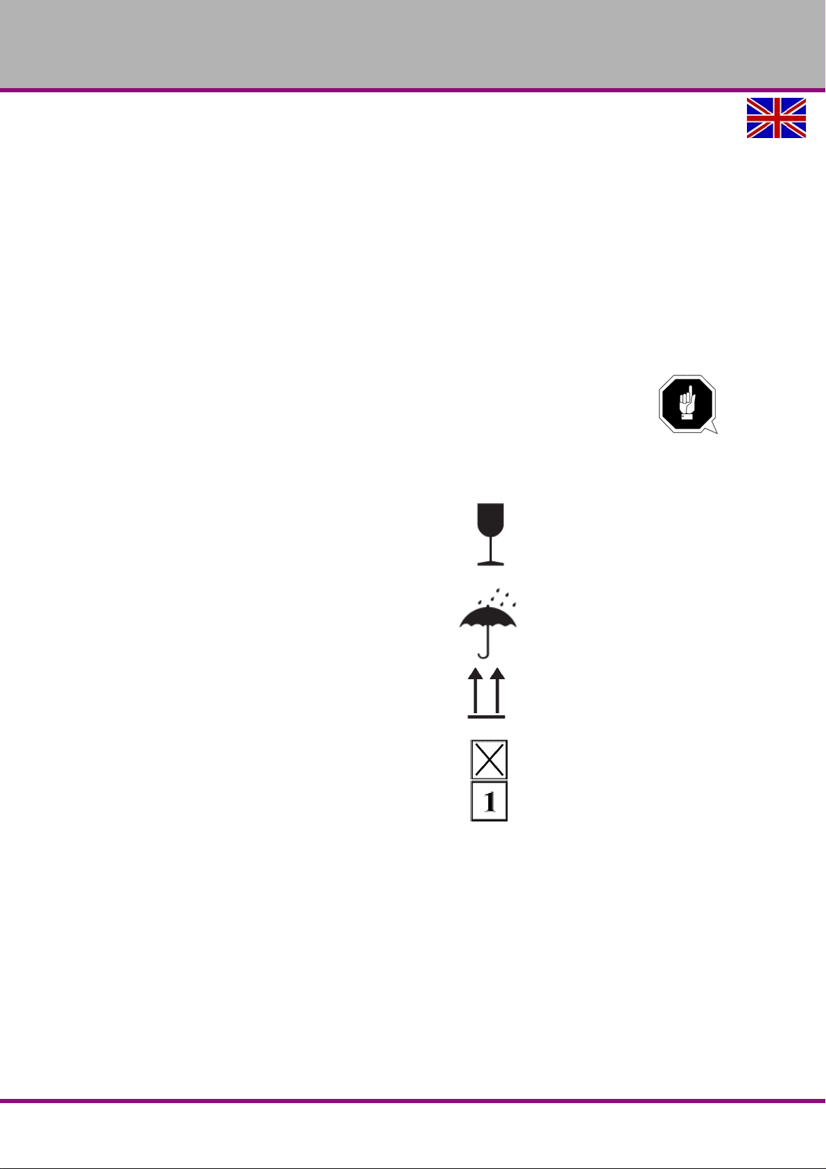
OPTIMUM
MASCHINEN - GERMANY
Neither are the following items covered by liability or warranty claims:
- Wearing parts and components which are subject to normal and intended wear, such as
V-belts, ball bearings, lighting, filters, seals, etc.
- Non reproducible software errors
Any services, which OPTIMUM Gmb H or one of its agen ts performs in orde r to fulfil any
additional warranty are neither an acceptance of the defects nor an acceptance of its obligation to compensate. These services neither delay nor interrupt the warranty period.
The court of jurisdiction for legal disputes between businessmen is Bamberg.
If any of the a forementi oned agreeme nts is totally or partially in operative and/o r invalid, a
provision which nearest approaches the intent of the guarantor and remains within the
framework of the limits of liability and warranty which are specified by this contract is
deemed agreed.
8.5 Storage
ATTENTION!
Incorrect and improper storage might result in damage or destruction of electrical and
mechanical machine components.
Store packed and unpacked parts only under the intende d environmental conditions.
Follow the instructions and information on the transport box:
Fr agile goods
(Goods require careful handling)
Protect against moisture and humid environment
Prescribed position of the packing case (Marking
of the top surface - arrows pointing to the top)
Maximum stacking height
Example: not stackable - do not stack further
packing case on top of the first one.
Consult Optimum Maschinen Germany GmbH if the milling machine and accessories are stored
for more than three months or are stored under different environmental conditions than those
specified here.
"Environmental conditions - storage“ on page 19
MT50E_GB_appendix.fm
MT50EGB
Version 1.0 dated 2017-05-24Page 60 Translation of the original instructions
Appendix
Page 61

OPTIMUM
MASCHINEN - GERMANY
8.6 Advice for disposal / Options of re-use
Please dispose of your machine in an environmentally friendly way, not by disposing of the
waste not in the environment, but by acting in a professional way.
Please neither throw away the packaging nor the used machine later on, but dispose of them
according to the guidelines established by your city council/municipality or by the corresponding
waste management enterprise.
8.6.1 Decommissioning
CAUTION !
Immediately decommission used machines in order to avoid later misuse and
endangering of the environment or of persons.
Cut the connection cable.
Remove all environmentally hazardous operating fluids from the used device.
If applicable remove batteries and accumulators.
Disassemble the machine if required into easy-to-handle and reusable assemblies and
component parts.
Dispose of machine components and operating fluids using the intended disposal
methods.
8.6.2 Disposal of new device packaging
All used packaging materials and packaging aids from the machine are recyclable and generally need to be supplied to the material reuse.
The packaging wood can be supplied to the disposal or the reuse.
Any packaging components made of cardboard box can be chopped up and supplied to the
waste paper collection.
The films are made of polyethylene (PE) and the cu shion parts are made of polystyrene (PS).
These materials can be reused after reconditioning if they are passed to a collection station or
to the appropriate waste management enterprise.
Only forward the packaging materials correctly sorted to allow direct reuse.
8.6.3 Disposal of the machine
INFORMATION
Please take care in your interest and in the interest of the environment that all
component parts of the machine are only disposed of in the intended and admitted way.
Please note that the electrical devices comprise a variety of reusable materials as well as
environmentally hazardous components. Please ensure that these components are
disposed of separately and professionally. In case of doubt, please contact your
municipal waste management. If appropriate, call on the help of a specialist waste
disposal company for the treatment of the material.
8.6.4 Disposal of electrical and electronic components
Please make sure that the electric al components are disposed of professionally and according
to the statutory provisions.
The device is composed of electrical and electronic components and must not be disposed of
as household waste. According to the European Directive 2011/65/EU regarding electrical and
electronic used devices and the implementation of national legislation, used power tools and
electrical machines need to be collected separately and supplied to an environmentally friendly
recycling centre.
MT50E_GB_appendix.fm
Appendix
Version 1.0 dated 2017-05-24 Page 61Translation of the original instructions
MT50E GB
Page 62

OPTIMUM
MASCHINEN - GERMANY
As the machine operator, you should obtain information regarding the authorised collection or
disposal system which applies for your company.
Please make sure that the electrical components are disposed of professionally and according
to the legal regulations. Please only t hrow deple ted ba tteries in th e collectio n boxes in shops or
at municipal waste management companies.
8.6.5 Disposal of lubricants and coolants
ATTENTION!
Please imperatively make sure to dispose of the used coolant and lubricants in an
environmentally compatible manner. Observe the disposal instructions of your
municipal waste management companies.
INFORMATION
Used coolant emulsions and oils should not be mixed since it is only possible to reuse
oils without pre-treatment when they have not been mixed.
The disposal instructions for used lubricants are made available by the manufacturer of
the lubricants. If necessary, request the product-specific data sheets.
8.7 Disposal through municipal collection facilities
Disposal of used electrical and electro nic com pone n ts
(Applicable in the countries of the European Union and other European countries with a separate collecting system for those devices).
The sign on the product or on its packing indicates that the product must not be handled as
common household waste, but that is needs to be disposed of at a central collection point for
recycling. Your contribution to the correct disposal of this product will protect the environment
and the public health. Incorrect disposal constitutes a risk to the environment and public health.
Recycling of material will help reduce the consumption of raw materials. For further information
about the recycling of this product, please consult your District Office, municipal waste collection station or the shop where you have purchased the product.
8.8 Terminology/Glossary
Term Explanation
Cross table Supporting surface, clamping surface for the workpiece with traverse in X
and Y directions
Taper mandrel Tool housing taper, drill taper, drill chuck taper.
Workpiece piece to be milled, drilled or machined.
Draw bar Threaded rod to fix the taper mandrel in the quill.
Drill chuck Drill bit adapter
Collet Holder for end mill
Drill-mill head Upper part of the milling machine
Quill Hollow shaft in which the milling spindle turns.
Milling spindle Shaft activated by the motor
Drilling table Supporting surface, clamping surfa c e
Taper mandrel Cone of the drill or of the drill chuck
Spindle sleeve lever Manual operation for the drill feed
MT50E_GB_appendix.fm
MT50EGB
Version 1.0 dated 2017-05-24Page 62 Translation of the original instructions
Appendix
Page 63

Term Explanation
OPTIMUM
MASCHINEN - GERMANY
Quick action Drill chuck
Tool Milling cutter, drill bit, etc.
Drill bit adapter can be fixed by hand.
MT50E_GB_appendix.fm
Appendix
Version 1.0 dated 2017-05-24 Page 63Translation of the original instructions
MT50E GB
Page 64

OPTIMUM
MASCHINEN - GERMANY
EC - Declaration of Conformity
in accordance with the Machinery Directive 2006/42/EC Annex II 1.A
The manufacturer/
distributor:
hereby declares that the following product
Product designation: MT50E
Type designation: Milling machine
Serial number: __ __ __ __ __
Year of manufacture: 20__
Manually controlled milling machine with power-driven axis feed rates up to 2 m/min and digital position display for craft and industrial plants which meets all the relevant provisions of the above mentioned Directive
2006/42/EC as well as the other directives applied (below) including their amendments in force at the time
of declaration. The following other EU Directives have been applied: EMC Directive 2014/30/EC, Low Voltage Directive 2014/35/EC The safety objective meet the requirement of EC Directive 2006/42/EC.
The following harmonized standards were applied:
EN 13128:2001+A2:2009/AC:2010 - Safety of machine tools - Milling machines (including boring machines)
EN 60204-1:2006/AC 2010: Safety of machinery - Electrical equipment of machines - Part 1: General
requirements
EN ISO 13849 - Safety of machinery - Safety-related parts of control systems
EN ISO 12100:2010 - Safety of machinery - General principles for design - Risk assessment and risk
reduction
Optimum Maschinen Germany GmbH
Dr.-Robert-Pfleger-Str. 26
D - 96103 Hallstadt
Documentation Manager: Kilian Stürmer, phone: +49 (0) 951 96 96555-800
Address: Dr.-Robert-Pfleger-Str. 26
D - 96103 Hallstadt
Kilian Stürmer
Hallstadt, den 2017-05-22
MT50E_CE_en.fm
Page 65

Index
OPTIMUM
MASCHINEN - GERMANY
A
Accessories ...........................................................21
Accident report
Anchored mounting
......................................................16
...............................................25
C
Clamping the tool ..................................................30
Commissioning
Copyright
Cross table
Turning
Customer service
Customer service technician
.....................................................27
...............................................................59
.............................................................34
..................................................39
.................................39
D
Declaration of conformity ......................................64
Dimensions
Disinfection
Cooling lubricant tank
Disposal
...........................................................18
......................................53
................................................................62
E
EC - declaration of conformity ...............................64
EC declaration
Electrical connection
Electronics
Emergency stop condition
reset
Emergency-stop button
Environmental conditions
......................................................64
.............................................18
............................................................16
.................................................................30
.........................................13
......................................19
F
Feed motor ............................................................33
First commissioning
..............................................27
I
Inspection ..............................................................37
L
Lubrication ............................................................27
M
Maintenance work .................................................16
Maintenance, Inspection
Malfunctions
Master switch
Milling head
swivelling
Zero position
Mounting
anchored
..........................................................57
..................................................13, 15
.........................................................32
....................................................34
..........................................................25
.......................................36
O
Obligations
of the operating company
of the operator
Operation
operator's log
..............................................................29
.................................................11
........................................................36
................................11
P
Panels ...................................................................29
Power failure
.........................................................30
Prohibition, warning and mandatory signs
Protective
equipment
........................................................14
............13
Q
Qualification of personnel
Safety
..............................................................10
Quill feed
coarse adjustment
Fine adjustment
...........................................32
...............................................32
R
Restoring
readiness for operation
....................................30
S
Scope of delivery ..................................................23
Specialist dealer
Speed table
horizontal milling
vertical milling
Spindle capacity
Spindle sleeve feed
Storage and packaging
Switching on
Switching on the machine
Swivelling the milling head
...................................................39
..............................................31
..................................................31
...................................................20
..............................................32
.........................................23
.........................................................29
.....................................29
...................................32
T
Technical specification .........................................18
Dimensions
Electrical connection
Environmental conditions
Work area
Transport
......................................................18
........................................18
................................19
........................................................19
..............................................................23
U
Using lifting equipment .........................................16
W
Warming up the machine ......................................27
Work area
.............................................................19
Version 1.0 dated 2017-05-24 Page 65Translation of the original instructions
MT50E GB
Page 66

OPTIMUM
MASCHINEN - GERMANY
MT50EGB
Version 1.0 dated 2017-05-24Page 66 Translation of the original instructions
 Loading...