

Page 1
OPTIMUM
3336030
MASCHINEN - GERMANY
Operating manual
Version 1.3.0
Multi-functional milling machine
GB
Page 2

OPTIMUM
MASCHINEN - GERMANY
Table of contents
1 Safety
1.1 Type plate.................................................................................................................................................4
1.2 Safety instructions (warning notes)...........................................................................................................5
1.2.1 Classification of hazards...........................................................................................................................5
1.2.2 Other pictograms......................................................................................................................................5
1.3 Intended use.............................................................................................................................................6
1.4 Reasonably foreseeable misuses.............................................................................................................7
1.4.1 Avoiding misuses......................................................................................................................................7
1.5 Possible dangers caused by the milling-machine.....................................................................................8
1.6 Qualification of personnel.........................................................................................................................9
1.6.1 Target group.............................................................................................................................................9
1.6.2 Authorized personnel..............................................................................................................................10
1.7 Operator positions ..................................................................................................................................10
1.8 Safety devices ........................................................................................................................................10
1.8.1 Lockable main switch................................................ ... ...........................................................................11
1.8.2 EMERGENCY STOP push button............................ ... .................................................. .........................11
1.8.3 Protective cover pulleys..........................................................................................................................11
1.8.4 Separating protective equipment................................. .. ... ......................................................................11
1.8.5 Milling table............................................................... ..............................................................................12
1.9 Prohibition, warning and mandatory labels.............................................................................................12
1.9.1 Control technical protection ...................................................................................................................12
1.9.2 Prohibition, warning and mandatory labels.............................................................................................12
1.10 Safety check...........................................................................................................................................12
1.11 Personnel protective equipment .............................................................................................................13
1.12 Safety during operation...........................................................................................................................13
1.13 Safety during maintenance.....................................................................................................................14
1.14 Switching-off and securing the milling-machine. .... .................................................................................14
1.14.1 Using lifting equipment ...........................................................................................................................15
1.14.2 Mechanical maintenance work ...............................................................................................................15
1.15 Accident report........................................................................................... ... ..........................................15
1.16 Electrical system.....................................................................................................................................16
1.17 Inspection deadlines...............................................................................................................................16
1.18 Clamping devices for workpieces and tools............................................................................................16
2 Technical data
2.1 Electrical connection...............................................................................................................................17
2.2 Dimensions.............................................................................................................................................17
2.3 Milling capacity / removal.................................................. ... ...................................................................17
2.4 Adjustment travels / swiveling range ......................................................................................................17
2.5 Speeds / feeds........................................................................................................................................18
2.6 Operating material..................................................................................................................................18
2.7 Environmental conditions.................................................................................... ....................................18
2.7.1 Emissions ...............................................................................................................................................18
3 Assembly
3.1 Scope of delivery....................................................................................................................................20
3.2 Transport ................................................................................................................................................20
3.3 Load suspension point............................................................................................................................20
3.4 Installation and assembly .......................................................................................................................21
3.4.1 Installation site requirements..................................................................................................................21
3.4.2 Installation...............................................................................................................................................21
3.5 Fastening................................................................................................................................................22
3.6 First commissioning................................................................................................................................24
MF2 V a rioGB
Version 1.3.0 dated 2016-12-16Page 2 Original operating instructions
Page 3

OPTIMUM
MASCHINEN - GERMANY
3.7 Warming up the machine .......................................................................................................................24
3.8 Electrical connection ..............................................................................................................................24
3.9 Electrical connection of machines with frequency converter..................................................................25
3.9.1 Regulated drives in connection with residual current devices................................................................25
3.9.2 Protection from Dangerous Shock Currents, use of ELCBs...................................................................25
3.9.3 Current in the protective earth conductor - Leakage current...................... .. ..........................................25
3.9.4 When the ELCB triggers.........................................................................................................................26
4Operation
4.1 Overview ................................................................................................................................................27
4.1.1 Control panel..........................................................................................................................................28
4.1.2 Safety devices....................... ... ................................................ ... ..........................................................28
4.1.3 Separating protective equipment............................................................................................................28
4.2 Design of the multi-milling machine MF2 Vario......................................................................................29
4.2.1 Spindle head ..........................................................................................................................................29
4.2.2 Switch cabinet........................................................................................................................................29
4.2.3 Coolant pump.........................................................................................................................................29
4.3 Safety.....................................................................................................................................................30
4.3.1 Warming up the machine .......................................................................................................................30
4.4 Switching the machine on and off ..................................................... ... ..................................................30
4.4.1 Switch on................................................................................................................................................30
4.4.2 Switching off.............................. ................................................... ..........................................................30
4.4.3 Locking the main switch.........................................................................................................................30
4.5 Raising / lowering the cross table...........................................................................................................31
4.6 Moving the cross table left or right (X-axis)............................................................................................32
4.6.1 Manual movement on the X axis............................................................................................................32
4.6.2 Automatic movement of the X-axis using the feed motor.......................................................................33
4.7 Moving the cross table forward / back (Y-axis) ......................................................................................33
4.8 Inclining the spindle head up or down....................................................................................................34
4.9 Orienting the spindle head to the right or left .........................................................................................35
4.10 Moving the spindle head-holder forward or back ...................................................................................35
4.11 Turning the spindle head-holder.............................................................................................................36
4.12 Adjusting the spindle speed ...................................................................................................................36
4.13 Pulleys....................................................................................................................................................36
4.13.1 Gear switch ..................................... ... .. ..................................................................................................37
4.13.2 Fine adjustment of the motor speed.......................................................................................................38
4.14 Spindle Left - Stop - Right selector.......................................................................................
4.15 Spindle brake .........................................................................................................................................38
4.16 Drill depth stop ..................................... ... ................................................... ............................................38
4.16.1 End stop operating lever ........................................................................................................................39
4.17 Spindle sleeve feed................................................................................................................................ 39
4.17.1 Manual spindle sleeve feed....................................................................................................................39
4.17.2 Automatic spindle sleeve feed................................................................................................................40
4.17.3 Feed reverse button...............................................................................................................................41
4.18 Cooling agent .........................................................................................................................................41
4.19 Tool change............................................................................................................................................42
4.19.1 Installation..............................................................................................................................................42
4.19.2 Disassembly..........................................................................................................................................42
4.20 Stopping the machine in the event of an emergency ............................................................................43
4.20.1 Position of the emergency stop knob.....................................................................................................43
5 Cleaning, maintenance, repair
5.1 Safety.....................................................................................................................................................44
5.1.1 Measures before repair works................................................................................................................44
5.1.2 Notes for repair.......................................................................................................................................44
5.1.3 Measures before switching on again and after repair measures............................................................44
..................38
Version 1.3.0 dated 2016-12-16 Page 3Original operating instructions
MF2 Vario GB
Page 4

OPTIMUM
MASCHINEN - GERMANY
5.2 Cleaning..................................................................................................................................................44
5.3 Lubricating..............................................................................................................................................45
5.4 Maintenance...........................................................................................................................................46
5.5 Repair.....................................................................................................................................................47
5.5.1 Customer service technician...................................................................................................................47
5.6 Cooling lubricants and tanks...................................................................................................................48
5.6.1 Inspection plan for water-mixed cooling lubricants.................................................................................49
6 Ersatzteile - Spare parts - MF2 Vario
6.1 Spindelkopf Multifräsmaschine - Multi-milling machine spindle head.....................................................50
6.2 Grundkörper Multifräsmaschine - Body of the multi-milling machine......................................................54
6.3 Spindeln Frästisch - Spindles milling table.............................................................................................57
6.4 Zentralschmierung - Central lubrication................................................................... ... ............................59
6.5 Spindelantrieb - Drive mechanism of the spindle ...................................................................................60
6.6 Bedienpanel ab Jahr 2016 - Control panel from year 2016....................................................................63
6.7 Maschinenschilder - Machine labels.......................................................................................................64
6.8 Schaltplan 1 von 2 - Wiring diagram 1 of 2.............................................................................................65
6.9 Schaltplan 2 von 2 - Wiring diagram 2 of 2.............................................................................................66
6.9.1 Ersatzteilliste elektrische Bauteile - Spare part list electrical components .............................................67
7 Malfunctions
7.1 Malfunctions on the multi-milling machine..............................................................................................70
8 Appendix
8.1 Copyright ................................................................................................................................................72
8.2 Terminology/Glossary.............................................................................................................................72
8.3 Change information operating manual....................................................................................................72
8.4 Liability claims for defects / warranty......................................................................................................73
8.5 Storage...................................................................................................................................................74
8.6 Note regarding disposal / options to reuse: ............................................................................................74
8.6.1 Decommissioning ...................................................................................................................................75
8.6.2 Disposal of the packaging of new devices..............................................................................................75
8.6.3 Disposing of the old device.....................................................................................................................75
8.6.4 Disposal of electrical and electronic components...................................................................................75
8.6.5 Disposal of lubricants and coolants ........................................................................................................76
8.7 Disposal via municipal collection............................................................................................................76
8.8 EC - Declaration of Conformity...............................................................................................................77
MF2 V a rioGB
Version 1.3.0 dated 2016-12-16Page 4 Original operating instructions
Page 5

OPTIMUM
MASCHINEN - GERMANY
Preface
Dear customer,
Thank you very much for purchasing a product made by OPTIMUM.
OPTIMUM metal working machines o ffer a maximum of quality, technically optimum solutions and convince
by an outstanding price performance ratio. Continuous enhancements and product innovations guarantee
state-of-the-art products and safety at any time.
Before commissioning the machine please thoroughly read these operating instructions and get familiar with
the machine. Please also make sure that all persons operating the machine have read and understood the
operating instructions beforehand.
Keep these operating instructions in a safe place nearby the machine.
Information
The operating instructions include indications for safety-relevant and proper installation, operation and maintenance of the machine. The continuous observance of all notes included in this manual guarantee the safety
of persons and of the machine.
The manual determines the intended use of the machine and includes all necessary information for its economic operation as well as its long service life.
In the paragraph "Maintenance" all maintenance works and functional tests are described which the operator
must perform in regular intervals.
The illustration and information included in the present manual can possibly deviate from the current state of
construction of your machine. Be ing the manufacturer we are continuously seeking for improv ements and
renewal of the products. Therefore, changes might be performed without prior notice. The illustrations of the
machine may be different from the illustrations in these instructions with regard to a few details. However,
this does not have any influence on the operability of the machine.
Therefore, no claims may be derived from the indications and descr i ptions. Changes and er rors ar e re served !
Your suggestion with regard to these operating instructions are an important contribution to optimising our
work which we offer to our customers. For any questions or suggestions for improvement, please do not hesitate to contact our service department.
If you have any further questions after reading these operating instructions and you are not able to
solve your problem with a help of these operating instructions, please contact your specialised
dealer or directly the company OPTIMUM.
Optimum Maschinen Germany GmbH
Dr.- Robert - Pfleger - Str. 26
D-96103 Hallstadt
Mail: [email protected]
Internet: www.optimum-maschinen.com
Version 1.3.0 dated 2016-12-16 Page 5Original operating instructions
MF2 Vario GB
Page 6
OPTIMUM
NO.
SN
Year
MF 2V
3336030
DE
EN
ES
FR
IT
CZ
DK
FI
GR
HU
NL
PL
PT
RO
RU
SL
TR
Fräsmaschine
Milling machine
Fresadora
Fraiseuse
Fresatrice
Univerzální frézka
Freesmachine
Porajyrsin
Φρεζοδραπανο
Multifunkciós marógép
Freesmachine
Frezarka
Φ
резерный станок
Frezalni stroj
Freze Tezgahı
Màquina freadora
Maşină de frezat
5002
MASCHINEN - GERMANY
1 Safety
Glossary of symbols
gives further advice
calls on you to act
enumerations
This part of the operating instructions
expl ains the meaning and use of the warning notices included in these operating instruc-
tions,
defines the intended use of the milling-machine.
points out the dangers that might arise for you or others if these instructions are not
observed,
informs you about how to avoid dangers.
In addition to these operation instructions, please observe
the applicable laws and regulations,
the legal regulations for accident prevention,
the prohibition, warning and mandatory signs as well as the warning labels on the milling-
machine.
When installing, operating, maintaining and repairing the milling machine it is necessary to
observe the European standards.
With regard to relevant national legislation which has not yet been adjusted to the Euro pean
standards, the applicable national legislation needs to be observed .
If required it is necessary to take the corresponding measures to comply with the country-specific regulations before commissioning the milling-machine.
Always keep this documentation close to the milling-machine.
INFORMATION
If you are unable to solve a problem using these operating instructions, please contact us for
advice:
Optimum Maschinen Germany GmbH
Dr. Robert-Pfleger-Str. 26
D-96103 Hallstadt
Email: [email protected]
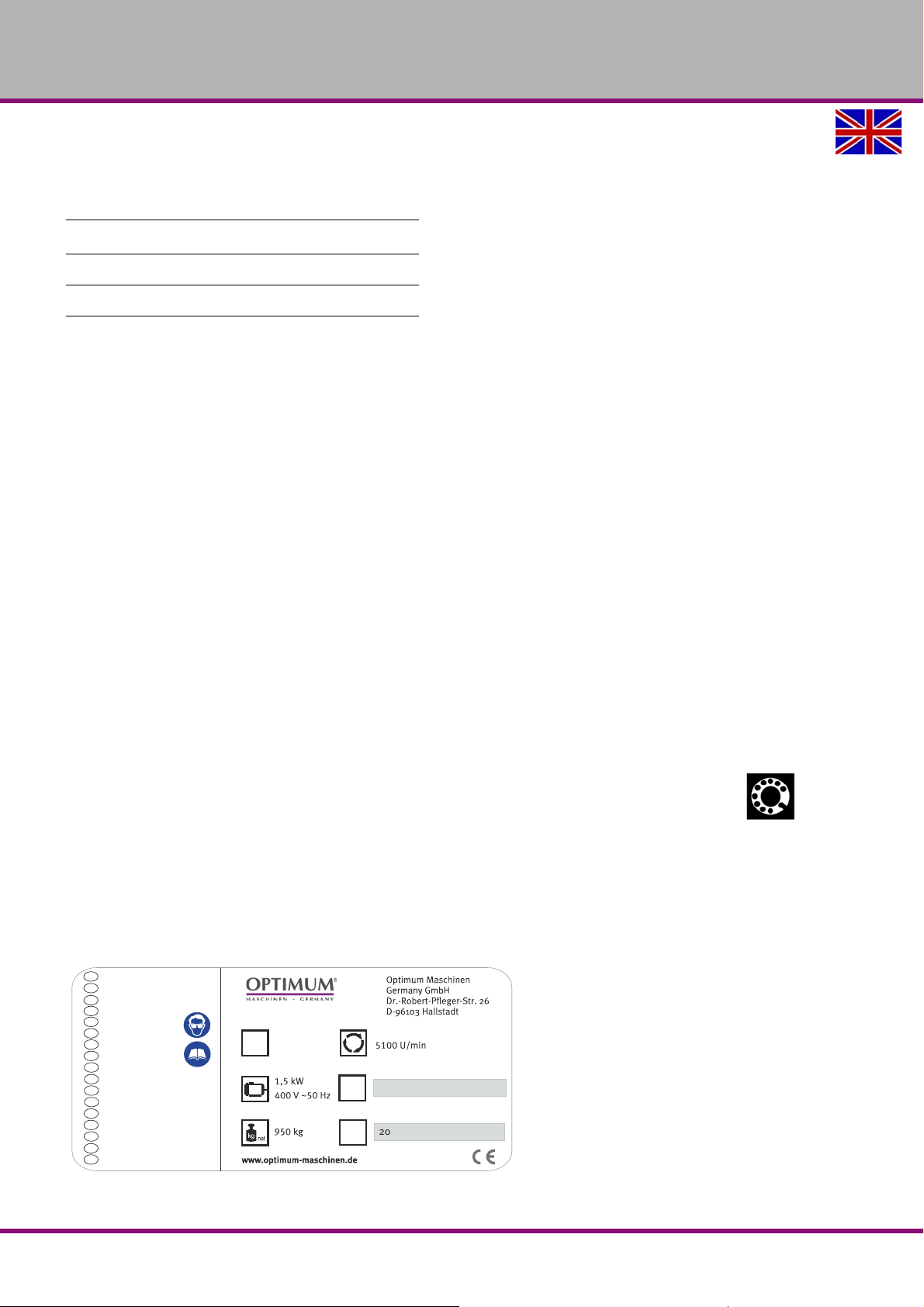
1.1 Type plate
MF2 VarioGB
Version 1.3.0 dated 2016-12-16Page 4 Original operating instructions
Page 7
OPTIMUM
MASCHINEN - GERMANY
1.2 Safety instructions (warning notes)
1.2.1 Classification of hazards
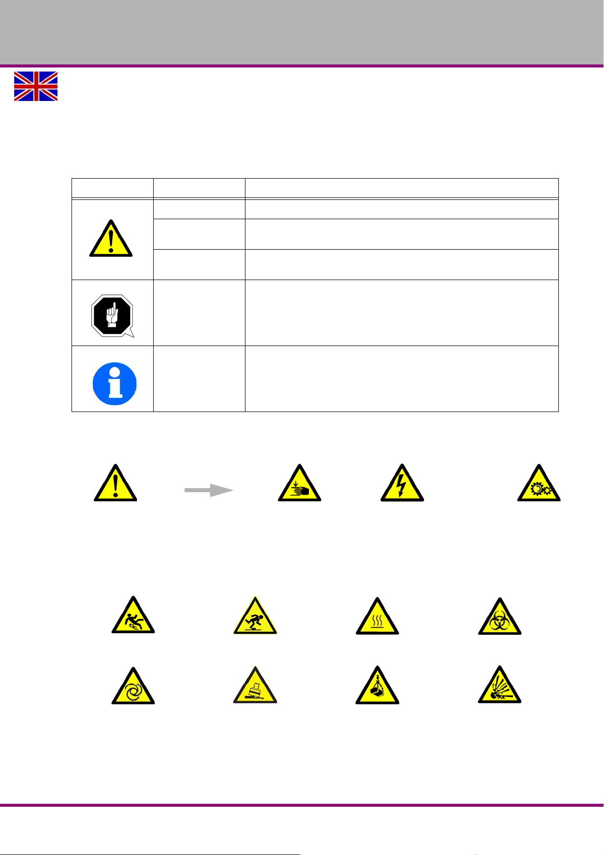
We classify the safety warnings into various levels. The table below gives an overview of the
classification of symbols (ideogram) and the warning signs for each specific danger and its
(possible) consequences.
Ideogram Warning alert Definition / consequence
DANGER!
WARNING!
CAUTION!
ATTENTION!
INFORMATION
In case of specific dangers, we replace the pictogram by
Threatening danger that will cause serious injury or death to people.
A danger that might cause severe injury to the personnel or can lead to
death.
Danger or unsafe procedure that might cause injury to people or damage
to property.
Situation that could cause damage to the milling machine and products
and other types of damage.
No risk of injury to people.
Application tips and other important or useful information and notes.
No dangerous or harmful consequences for people or objects.
or
general danger by a warning of injury of hands, hazardous electrical
voltage,
1.2.2 Other pictograms
Warning danger of slipping!
Warning of automatic
start-up!
Warning risk of stumbling!
Warning tilting danger! Warning of suspended
Warning hot surface!
loads!
rotating parts.
Warning biological hazard!
Caution, danger of
explosive substances!
MF2 Vario GB
Version 1.3.0 dated 2016-12-16 Page 5Original operating instructions
Page 8
OPTIMUM
MASCHINEN - GERMANY
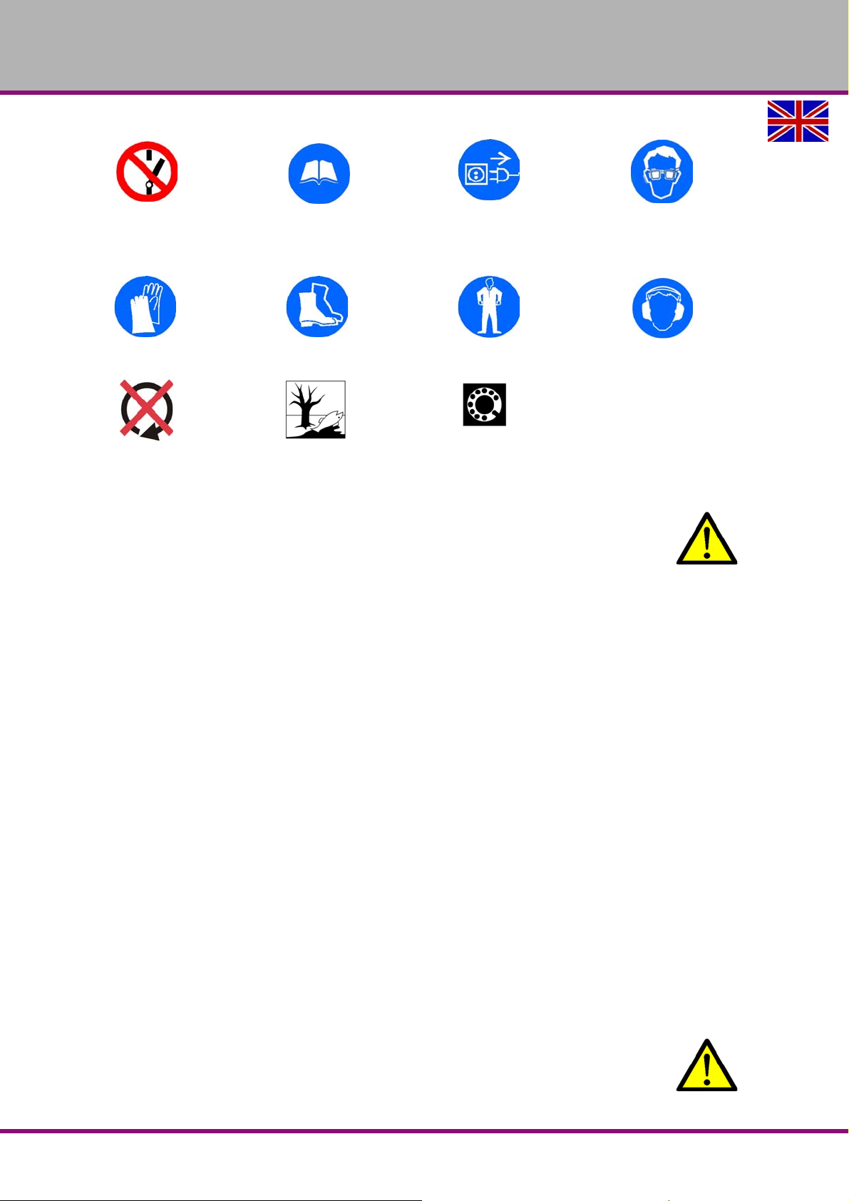
Activation forbidden!
Use protective gloves! Use protective boots! Use protective suit! Use ear protection!
Only switch in standstill! Protect the environment!
Read the operating
instructions before
commissioning!
Disconnect the mains plug! Use protective glasses!
Contact address
1.3 Intended use
WARNING!
In the event of improper use, the milling-machine
will endanger personnel,
the milling-machine and other material property of the operating company will be
endangered,
the correct function of the milling-machine may be affected.
The milling-machine is designed and manufactured to be used for milling and drilling cold metals or other non-flammable materials or materials that do not constitute a health hazard by
using commercial milling and drilling tools.
Using this machine it is possible to perform dry process ing as well as processing by using cooling lubricants.
The limit values of the balances of the tools need to be observed.
The milling-machine must only be installed and operated in a dry and well-ventilated place.
The milling-machine is designed and manufactured to be used in a non-explosive environment.
approval of the company Optimum Maschinen Germany GmbH then the milling-machine is
being used improperly.
We will not be held liable for any damages resulting from any operation which is not in accordance with the intended use.
We expressly point out that the guarantee or CE conformity will expire due to any constructive
technical or procedural changes which had not been performed by the company Optimum
Maschinen Germany GmbH.
It is also part of intended use that
the maximum values for the milling-machine are complied with,
the operating manual is observed,
the inspection and maintenance instructions are observed.
Intended useIf the milling-machine is used in any way other than described above, modified without the
WARNING!
Heaviest injuries through improper use.
MF2 VarioGB
Version 1.3.0 dated 2016-12-16Page 6 Original operating instructions
Page 9
OPTIMUM
MASCHINEN - GERMANY
It is forbidden to make any modifications or alternations to the operation values of the
milling-machine. They could endanger the personnel and cause damage to the millingmachine.
INFORMATION
The control and drive components of the machine are approved for industrial and comm ercial
use within industrial supply systems. Utilization in public supply systems requires another configuration and/or additional measures.
WARNING!
The milling machine is not intended for use in residential facilities where the power is
supplied via a public low voltage supply system. In these areas, it may be difficult to
guarantee electromagnetic compatibility due to conducte d and emitted interference.
ATTENTION!
If the milling machine is not used as intended or if the safety directives or the operating
instructions are ignored the liability of the manufacturer for any damages to personnel
or objects resulting hereof is excluded and the claim under guarantee is becoming null
and void!
1.4 Reasonably foreseeable misuses
Any other use as the one determined under the "Intended use" or any use beyond the
described use shall be deemed as not in conformity and is forbidden.
Any other use has to be discussed with the manufacturer.
It is only allowed to process metal, cold and non-inflammable materials with the milling-
machine.
In order to avoid misuses it is necessary to read and understand the operating instructions
before the first commissioning.
The operators must be qualified.
1.4.1 Avoiding misuses
Use of suitable cutting tools.
Adapting the speed adjustment and feed to the material and workpiece.
Clamp workpieces firmly and vibration-free.
ATTENTION!
The workpiece is always to be fixed by a machine vice, jaw chuck or by another
appropriate clamping tool such as for the clamping claws.
WARNING!
Risk of injury caused by workpieces flying off.
Clamp the workpiece in the machine vice. Make sure that the workpiece is firmly clamped in the
machine vice resp. that the machine vice is firmly clamped on the machine table.
Use cooling and lubricating agents to increase the durability of the tool and to improve the
surface quality.
Clamp the cutting tools and workpieces on clean clamping surfaces.
Sufficiently lubricate the machine.
Correctly adjust the bearing clearance and the guidings.
Version 1.3.0 dated 2016-12-16 Page 7Original operating instructions
MF2 Vario GB
Page 10
OPTIMUM
MASCHINEN - GERMANY
It is recommended:
Insert the drill in a way that it is exactly positioned between the three clamping jaws of the
quick action chuck.
Clamp and mills by means of the collet chuck and the corresponding collets.
Clamp end face mills by means of shell end mill arbors.
When drilling make sure that
the suitable speed is set depending on the diameter of the drill,
the pressure must only be such that the drill can cut without load
in case of too strong pressure the drill will get worn early or even might break resp. get
jammed in the hole. If the drill gets jammed immediately stop the main motor by pressing
the emergency stop button,
for hard materials, e.g. steel, use commercial cooling / lubricating agents,
generally always drive the turning spindle out of the workpiece.
ATTENTION!
Do not use the quick action drill chuck for milling tools. Never clamp a milling cutter into
a quick action drill chuck. Use a collet chuck with collets for the end mill.
When milling make sure that
the corresponding cutting speed is selected,
for workpieces with normal strength values, e.g. steel 18-22 m/min,
for workpieces with high strength values 10-14 m/min,
the pressure is selected in a way that the cutting speed remains constant,
for hard materials commercial cooling / lubricating agents are used.
1.5 Possible dangers caused by the milling-machine
The milling-machine has undergone a safety inspection. The construction and type are state of
the art.
Nonetheless there remains a residual risk, since the milling-machine operates with
rotating parts,
electrical voltage and currents,
compressed air,
rapid moves.
We have used construction resources and safety techniques to minimize the health risk to personnel resulting from these hazards.
If the milling-machine is used and maintained by the personnel who are not duly qualified,
there may be a risk resulting from incorrect or unsuitable maintenance of the milling-machine.
INFORMATION
Everyone involved in the assembly, commiss ion ing , op e ra tio n an d main te na nc e mu st
be duly qualified,
strictly follow these operating instructions.
In the event of improper use
there may be a risk to the personnel,
there may be a risk to the milling-machine and other material values,
the correct function of the milling-machine may be affected.
Always switch off the milling-machine and disconnect it from the mains if you perform cleaning
or maintenance works.
MF2 VarioGB
Version 1.3.0 dated 2016-12-16Page 8 Original operating instructions
Page 11
OPTIMUM
MASCHINEN - GERMANY
WARNING!
The milling-machine may only be used with functional safety devices. Disconnect the
milling-machine immediately, whenever you detect a failure in the safety devices or
when they are not fitted!
All additional parts of the machine which had been added by the customer need to be
equipped with the prescribed safety devices.
This is your responsibility being the operating company!
"Safety devices“ on page 10
1.6 Qualification of personnel
1.6.1 Target group
This manual is addressed to
the operating companies,
operators having sufficient specialist knowledge,
the maintenance personnel.
Therefore, the warning notes refer to both, operation and maintenance personnel of the millingmachine.
Determine clearly and explicitly who will be responsible for the different activities on the millingmachine (operation, setting up, maintenance and re pair). Please note the name of the responsible person into an operators´s log.
INFORMATION
Unclear responsibilities constitute a safety risk!
Always lock the main switch after switching off the milling-machine. This will prevent it from
being used by unauthorized personnel.
The qualifications of the personnel for the different tasks are mentioned below:
Operator
The operator is instructed by the operating company about the assigned tasks and possible
risks in case of improper behaviour. Any tasks which need to be performed beyond the operation in the standard mode must only be performed by the operator if it is indicated in these
instructions and if the operating company expressively commissioned the operator.
Electrical specialist
Due to his professional training, knowledge and experience as well as his knowledge of respective standards and regulations the electrical specialist is able to perform works on the electrical
system and to recognise and avoid any possible dangers himself.
The electrical specialist is specially trained for the working environment in which he is working
and knows the relevant standards and regulations.
Qualified personnel
Due to their professional training, knowledge and experience as well as their knowledge of relevant regulations the qualified personnel is able to perform the assigned tasks and to recognise
and avoid any possible dangers themselves.
Instructed person
Instructed personnel were instru cted by the operating company about the assigned tasks and
any possible risks in case of improper behaviour.
Version 1.3.0 dated 2016-12-16 Page 9Original operating instructions
MF2 Vario GB
Page 12
OPTIMUM
MASCHINEN - GERMANY
1.6.2 Authorized personnel
INFORMATION
For working on the milling-machine sufficient expertise is required. No one must work
on the machine without having the necessary education, not even for a short while.
WARNING!
Inappropriate operation and maintenance of the milling-machine constitutes a danger for
the personnel, objects and the environment.
Only authorized personnel may operate the milling-machine !
Persons authorized to operate and maintain should be trained technical personnel and
instructed by the ones who are working for the operating company and for the manufacturer.
The operating company must
train the personnel,
instruct the personnel in regular intervals (at least once a year) on
- all safety standards that apply to the milling-machine,
- operation of the milling-machine,
- accredited technical guidelines,
- possible emergency situations,
check personnel‘s state of knowledge,
document training/instruction in a operation book,
require personnel to confirm participation in training/instructions by means of a signature,
check wh ether the personnel is working safety- and risk-conscious and observe the operat-
ing instructions.
The operator must
be specially trained in handling and programming the milling-machine,
know and understand the program sequence and which effects the individual process
parameters will have,
keep an operator‘s log,
before taking the machine in operation
- have read and understood the operating manual,
- be familiar with all safety devices and instructions.
For work on the following milling-machine parts there are additional requirements:
Electric components or operating materials: Must only be performed by a qualified electri-
cian or person working under the instructions and supervision of a qualified electrician.
Obligations of
the operating
company
Obligations of
the operator
Additional
requirements
regarding the
qualification
1.7 Operator positions
The operator position is in front of the milling-machine at the sight window or on the machine
control panel.
1.8 Safety devices
Use the milling-machine only with properly functioning safety devices.
Stop the milling-machine immediately if there is a failure on the safety device or if it is not func-
tioning for any reason.
It is your responsibility!
If a safety device has been activated or has failed, the milling-machine must only be used if you
have removed the cause of the failure,
have verified that there is no danger resulting for the personnel or objects.
MF2 VarioGB
Version 1.3.0 dated 2016-12-16Page 10 Original operating instructions
Page 13
OPTIMUM
MASCHINEN - GERMANY
WARNING!
If you bypass, remove or deactivate a safety device in any other way, you are
endangering yourself and other personnel working with the milling-machine. The
possible consequences are
injuries due to tools, workpieces or fragments hereof which are flying off at high
speed,
contact with rotating or moving parts,
a fatal electrocution,
seizing of clothes.
The milling machine includes the following safety devices:
a lockable main switch,
an EMERGENCY STOP push button,
two protective covers of the V-belt on the milling head,
a milling table with T-slots to fix the workpiece or the clamping device.
1.8.1 Lockable main switch
In the position " 0 " the lockable main switch can be secured against accidental or non-authorized switching-on by means of a padlock.
When the main switch is switched-off, the current supply is interrupted.
Except for the areas marked by the pictogram in the margin. In these areas there might be volt-
age, even if the main switch is switched-off.
WARNING!
Dangerous voltage even if the main switch is switched-off.
In the areas marked by the ideogram in the margin, there might be voltage, even if the main
switch is switched off.
1.8.2 EMERGENCY STOP push button
ATTENTION!
The EMERGENCY STOP push button immediately stops the operation of the milling-
machine.
Press the EMERGENCY STOP push button only if there is a risk! If this push button is
actuated in order to switch off the milling-machine in the standard operation the tool or
workpiece might get damaged.
After having actuated the EMERGENCY STOP, turn the knob of the particular push button to
the right in order to restart the machine.
Img.1-1: Control panel
1.8.3 Protective cover pulleys
Two protective covers for the belt pulleys is mounted on the drilling head. A switch is integrated
in the protective cover which controls if the system is close d.
INFORMATION
It is not possible to start the machine if the protective covers are not mounted.
1.8.4 Separating protective equipment
Adjust the protective equipment to the correct height before you start working.
To do so, detach the clamping sc rew, adjust the required height and re-tighten the clamping
screw.
Version 1.3.0 dated 2016-12-16 Page 11Original operating instructions
MF2 Vario GB
Page 14
OPTIMUM
MASCHINEN - GERMANY
A switch is integrated in the fixtur e of the spindle protection which monitors that the cover is
closed.
INFORMATION
You cannot start the machine if the spindle protection is not closed.
1.8.5 Milling table
Seats for T-slots are attached to the milling table.
WARNING!
Risk of injury due to parts flying off at high speed. Securely fix the workpiece on the
milling table.
1.9 Prohibition, warning and mandatory labels
INFORMATION
All warning signs must be legible. Check them regularly.
1.9.1 Control technical protection
WARNING!
If you bypass a controller you endanger yourself and other personnel working on the
milling-machine.
injuries due to tools, workpieces or fragments hereof which are flying off at high
speed,
contact with rotating parts,
fatal electrocution,
pulling-in of clothes.
If you bypass a controller in exceptional cases (e.g. during electrical repairs) short term you
must continuously monitor the milling-machine during this time.
1.9.2 Prohibition, warning and mandatory labels
INFORMATION
All warning and mandatory labels must be legible. Check them regularly.
1.10 Safety check
Check the milling-machine at least once per shift. Inform the person responsible immediately of
any damage, defect or change in operating function.
Check all safety devices
at the beginning of each shift (when the machine is operated continuously),
once per day (during one-shift operation),
once per week (when operated occasionally),
after every maintenance and repair work.
Check that prohibition, warning and information signs and the labels on the milling-machine
are legible (clean them, if necessary),
are complete (replace them, if necessary).
MF2 VarioGB
Version 1.3.0 dated 2016-12-16Page 12 Original operating instructions
Page 15
INFORMATION
Use the following table in order to organize the checks.
General check
Equipment Check
Protective covers Mounted, firmly bolted and not damaged
OPTIMUM
MASCHINEN - GERMANY
Signs,
Markings
Date: checked by (signature):
Functional check
Equipment Check
EMERGENCY-STOP
switch
Date: checked by (signature):
Installed and legible
When the EMERGENCY-STOP button is activated, the milling-machine
should switch off. Make sure that it is only possible to restart the
machine if the EMERGENCY STOP push button is unlocked and the
main switch was activated.
1.11 Personnel protective equipment
For certain work personal protective equipment is required.
Protect your face and eyes: Wear a safety helmet with facial protection when performing works
where your face and eyes are exposed to hazards.
Use protective gloves when handling pieces or tools with sharp edges.
Use safety shoes when you assemble, disassemble or transport heavy components.
Use ear protection if the noise level (emission) in the workplace exceeds 80 dB (A).
Before starting work make sure that the prescribed personnel protective equipment is available
at the working place.
CAUTION!
Dirty or contaminated personnel protective equipment can cause diseases. Clean it each
time after use and once a week.
1.12 Safety during operation
WARNING!
Before activating the milling-machine assure yourself that this will neither endanger
other personnel nor cause damage to equipment.
Avoid any unsafe working practices:
The instructions mentioned in these operating instructions have to be strictly observed dur-
ing assembly, operation, maintenance and repair.
Wear safety goggles.
Switch off the milling machine machine before measuring the workpiece.
Do not work on the milling-machine, if your concentration is reduced, for example, because
you are taking medication.
Version 1.3.0 dated 2016-12-16 Page 13Original operating instructions
MF2 Vario GB
Page 16
OPTIMUM
MASCHINEN - GERMANY
Observe the accident prevention regulations issued by your Employers Liability Insurance
Association or other competent supervisory authority, responsible for your company.
Inform the supervisor about all endangerments or errors.
Stay on the milling-machine until the movements are completely stopped.
Use the prescribed personnel protective equipment. Make sure to wear a well-fitting work
suit and, if necessary, a hairnet.
Do not use protective gloves when drilling or milling.
Switch off the milling machine on the main switch before changing the tool.
Use appropriate auxiliary materials to remove drilling and milling chips.
Make sure that nobody is endangered by your work.
Safely and firmly clamp the workpiece before switching on the milling machine.
CAUTION!
Risk due to inhaling of health hazardous dusts and mist.
Dependent on the material which need to be processed and the used auxiliaries dusts
and mist may be caused which might impair you health.
Make sure that the generated health hazardous dusts and mist are safely sucked off at
the point of origin and is dissipated or filtered from the working area. To do so, use a
suitable extraction unit.
WARNING!
When chipping magnesia materials (aluminium-/magnesium alloys) spontaneously
inflammable or explosive particles (powder, dust, chips) might be generated which might
result in a fire and/or an explosion (deflagration).
Magnesium is designated as a dangerous material in the list of dangerous materials and
preparations according to §4a of Ordinance of Hazardous Substances.
In case of a fire with magnesium only use appropriate and admitted extinguishing
agents. Never extinguish using water. If you extinguish burning magnesium with water it
might lead to dangerous reactions (detonating gas). Water would be decomposed in its
components hydrogen (H) and oxygen (O).
Only the following extinguishing agents are admitted:
solid extinguishing agent of the fire class D (fires of metals)
dr y covering salts for magnesium
a mixture of sand and cast chips
argon (Ar) or nitrogen (N
If fine mist and smoke is generated in the working room, suction unites need to provided
in order to avoid the accumulation of ignitable mixtures and emissions.
We specially point out the specific dangers when working with and on the milling-machine.
)
2
1.13 Safety during maintenance
Inform the operators in good time about any maintenance and repair works.
Report all safety relevant changes and performance details of the milling-machine. Document
all changes, have the operating instructions updated accordingly and train machine operators.
1.14 Switching-off and securing the milling-machine
Switch off the milling-machine by turning off the main switch before starting any maintenance
andrepair work.
Use a padlock to prevent the switch from being turned on without authorization and keep the
key in a safe place.
All machine parts as well as all dangerous tensions are switched off.
Excepted are only the positions which are marked with the adjoining pictogram. These positions
may be live even if the main switch is switched off.
MF2 VarioGB
Version 1.3.0 dated 2016-12-16Page 14 Original operating instructions
Page 17
OPTIMUM
MASCHINEN - GERMANY
Place a warning sign on the milling-machine.
WARNING!
Live parts and moves of machine parts can injure you or others dangerously!
Proceed with extreme care if you cannot switch off
the milling-machine by turning off the main switch due to required works (e.g. functional
control).
1.14.1 Using lifting equipment
WARNING!
The use of unstable lifting and load suspension gear that might break under load can
cause severe injuries or even death. Observe the accident prevention regulations issued
by your Employers Liability Insurance Association or other competent supervisory
authority, responsible for your company.
Check that the lifting equipment and load-suspension gears are of sufficient load
capacity and are in perfect condition.
Fasten the loads properly.
Never walk under suspended loads!
1.14.2 Mechanical maintenance work
Remove or install protection safety devices before starting any maintenance work and re-install
them once the work has been completed.This includes:
Covers,
Safety indications and warning signs,
earth (ground) connections.
If you remove protective or safety devices, re-fit them immediately after the completing the
work.
Check if they are working properly!
1.15 Accident report
Inform your superiors and Optimum Maschinen Germany GmbH immediately in the event of
accidents, possible sources of danger and any actions which almost led to an accident (near
misses).
There are many possible causes for "near misses".
The sooner they are notified, the faster the causes can be eliminated.
INFORMATION
We point out the specific dangers when performing works with and on the milling-machine
when describing such works.
Version 1.3.0 dated 2016-12-16 Page 15Original operating instructions
MF2 Vario GB
Page 18
OPTIMUM
MASCHINEN - GERMANY
1.16 Electrical system
Have the electrical equipment on the machine checked regularly. Immediately eliminate all
defects such as loose connections, defective wires, etc.
A second person must be present during work on live components to disconnect the power in
the event of an emergency. Immediately disconnect the milling machine if there are any anomalies in the power supply!
Comply with the required inspection intervals in accordance with the factory safety directive,
operating equipment inspection.
The operating company responsible for the machine must ensure that the electrical systems
and operating equipment are inspected with regards to their proper condition, namely,
by a qualified electrician or under the supervision and direction of a qualified electrician,
prior to initial start-up and after modifications or repairs, prior to restarting the equipment
and at certain intervals.
The deadlines must be set so that arising, foreseeable defects can be detected in a timely manner.
The relevant electro-technical rules must be followed during the inspection.
The inspection prior to initial operation is not required if the oper ator receive s confirma tion from
the manufacturer or installer that the electrical systems and operating equipment comply with
the accident prevention regulations.
Permanently installed electrical systems and operating equipment are considered constantly
monitored if they are continually serviced by qualified electricians and inspected by means of
measurements in the scope of operation (e.g. monitoring the insulation resistance).
1.17 Inspection deadlines
Define and document the inspection deadlines for the machine in accordance with § 3 of the
Factory Safety Act and perform an operational risk analysis in accordance with § 6 of the Work
Safety Act. Also use the inspection intervals in the maintenance section as reference values.
1.18 Clamping devices for workpieces and tools
ATTENTION!
Attention when taking over the existing clamping devices. Pleased check critically if the
clamping device is appropriate for your milling-machine.
Only use clamping devices which have a complete inherent stiffness.
Contac t the manufacture r of the clamping device regar ding the reuse of the clamping
devices after damages on the clamping devices due to collisions.
Correctly insert the workpiece and make sure that the machine is proper working
condition.
MF2 VarioGB
Version 1.3.0 dated 2016-12-16Page 16 Original operating instructions
Page 19
OPTIMUM
MASCHINEN - GERMANY
2 Technical data
The following information gives the dimensions and weight and is the manufacturer‘s
authorised machine data.
2.1 Electrical connection
Total connection rate 3 x 400 V; 50 Hz; 1.5 KW
Degree of protection IP 54
2.2 Dimensions
Taper ISO 40 (DIN 2080, DIN 69871)
Spindle sleeve diameter Ø 85.7 mm
Clamping surface of cross table 230 x 1244 mm
Max. dist. from spindle head to table 446 mm
Max. dist. from centre of spindle to upright 680 mm
Min. dist. from centre of spindle to upright 200 mm
Height 2150 mm
Width 1400 mm
Depth 1450 mm
Total weight 900 kg
Max. load of cross table 230 kg
Number of the T-slots 3
Size of the slot nut 16 x 63 mm
Throat depth 213 - 533 mm
2.3 Milling capacity / removal
End-milling cutter ø18 6 mm
Face milling cutter ø76 2.5 mm
MF2 Vario
2.4 Adjustment travels / swiveling range
Spindle sleeve travel 127 mm
Adjustment travel of cross table (X-axis) 800 mm
Adjustment travel of cross table (Y-axis) 305 mm
Vertical adjustment travel of cross table 406 mm
Swivel range spindle head carrier ± 90°
Up/down spindle head inclination ± 45°
Version 1.3.0 dated 2016-12-16 Page 17Original operating instructions
MF2 Vario GB
Page 20
OPTIMUM
MASCHINEN - GERMANY
2.4 Adjustment travels / swiveling range
Left/right spindle head swivelling range ± 90°
2.5 Speeds / feeds
Spindle speed 10 - 5100 min
Number of steps 6 and variable
Spindle sleeve feed per revolution of spindle 0,04; 0,08; 0,15 mm
-1
Feed speed
Of cross table (X-axis)
Fast motion speed
of cross table (X-axis)
Max. torque of feed 73.5 Nm
0.3 - 12 mm/second
15 mm/second
2.6 Operating material
Machine oil 628 Mobil (Vis. 100/150"
Grease Commercial bearing grease
2.7 Environmental conditions
Temperature 5 - 35 °C
Humidity 25-28 %
2.7.1 Emissions
Maximum sound pressure level at 1 m distance from the machine and 1.60 m above the ground
according to DIN ISO 8525 is 70 to 76 dB(A).
If the milling machine is installed in an area where various machines are in operation, the noise
exposure (immission) on the operator of the milling machine at the working place may exceed
80dB(A).
INFORMATION
This numerical value was measured on a new machine under proper operating conditions.
Depending on the age respectively on the wear of the machine it is possible that the noise
behaviour of the machine changes.
Furthermore, the factor of the noise emission is also depending on manufacturing influencing
factors, e.g. speed, material and clamping conditions.
INFORMATION
The mentioned numerical value is the emission level and not necessarily a safe working level.
Though there is a dependency between the degree of the noise emission and the degree of the
noise disturbance it is not possible to use it reliably to determine if further precaution measures
are required or not.
The following factors influence the actual degree of the noise exposure of the operator:
Character istics of the working area, e.g. size or damping behaviour,
Other noise sources, e.g. the number of machines,
MF2 VarioGB
Version 1.3.0 dated 2016-12-16Page 18 Original operating instructions
Page 21

OPTIMUM
MASCHINEN - GERMANY
Other processes taking place in the proximity and the period of time during which the operator is exposed to the noise.
Furthermore, it is possible that the admissible exposure level might be different from country to
country due to national regulations.
This information about the noise emission shall allow the operator of the machine to more easily evaluate the endangering and risks.
CAUTION!
Depending on the overall noise exposure and the basic limit values the machine
operators must wear an appropriate hearing protection.
We generally recommend to use a noise protection and a hearing protection.
Version 1.3.0 dated 2016-12-16 Page 19Original operating instructions
MF2 Vario GB
Page 22
OPTIMUM
MASCHINEN - GERMANY
3 Assembly
INFORMATION
The milling machine is delivered pre-assembled.
3.1 Scope of delivery
Check the milling machine immediately after delivery for transport damage, missing parts and
loose locking bolts.
Compare the scope of delivery with the attached packing list.
3.2 Transport
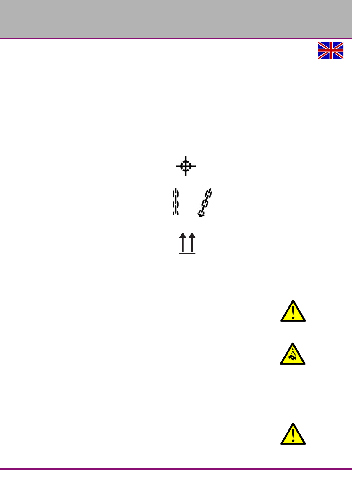
Centres of gravity
(Marking of the positions for the load suspension
gear)
Prescribed transportation position (Labelling of
the top surface)
Mean s of tr an sp or t to be use d
Weights
WARNING!
Severe or fatal injuries may occur if parts of the machine tumble or fall down from the
forklift truck or from the transport vehicle. Follow the instructions and information on
the transport box.
WARNING!
The use of unstable lifting and load suspension equipment that might break under load
can cause severe injuries or even death. Check that the lifting and load suspension gear
has sufficient load-bearing capacity and that it is in perfect condition.
Observe the accident prevention regulations issued by your Employers Liability
Insurance Association or other supervisory authorities applicable to your company.
Fasten the loads carefully.
Never walk under suspended loads!
3.3 Load suspension point
WARNING!
Check if all clamping screws of the spindle head carrier are tightened before lifting the
machine. see Img.4-12: “Moving the spindle head-holder forward or back“ on page 35.
MF2 VarioGB
Version 1.3.0 dated 2016-12-16Page 20 Translation of the original instructions
MF2V_3_GB.fm
Page 23
OPTIMUM
1
MASCHINEN - GERMANY
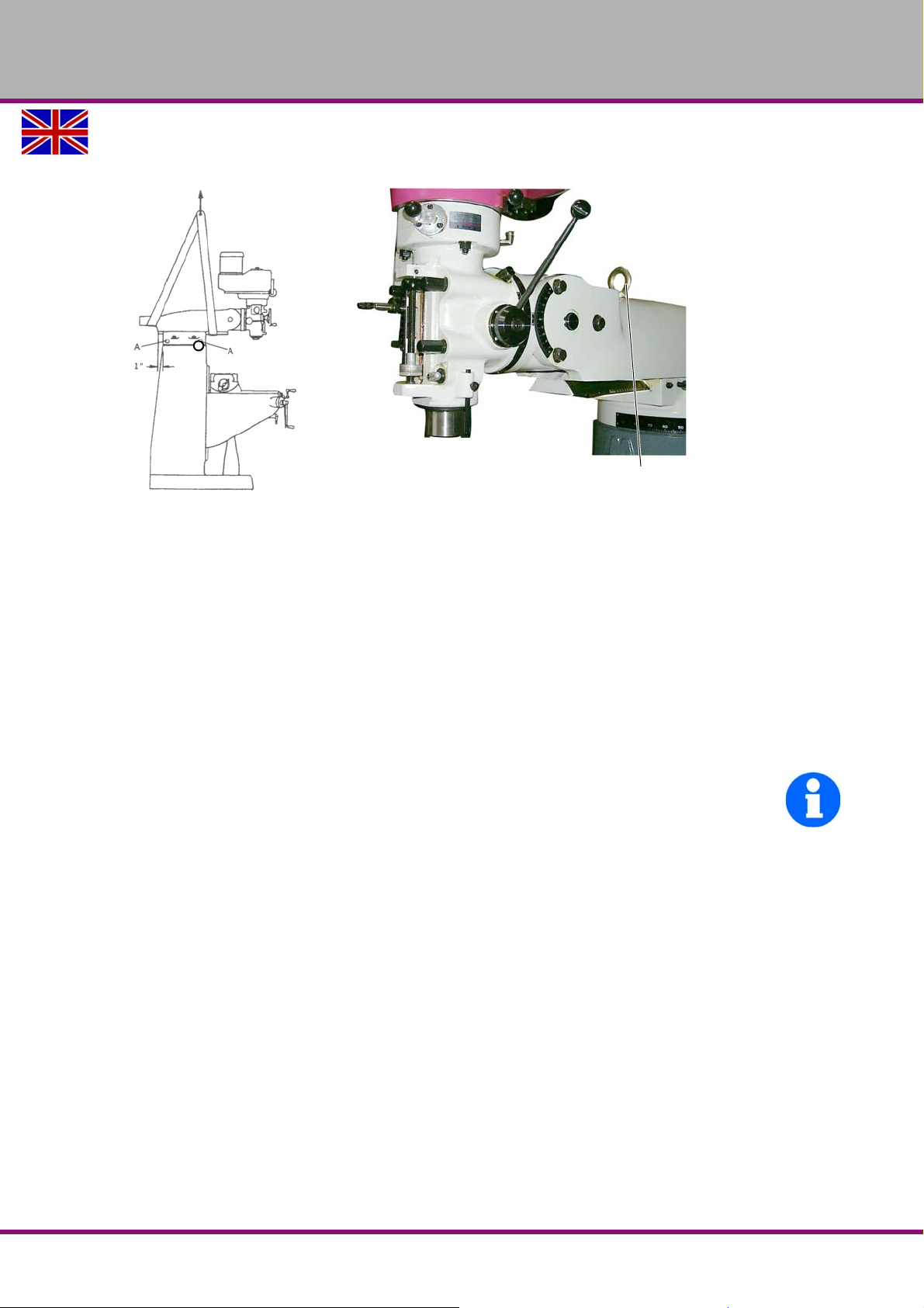
Raise the multi-milling machine, preferably using the eye bolt (1) located on the spindle
head holder.
Img.3-1: Lifting the machine using the eye bolt or a sling
Alternatively, the multi-milling machine can be Abbildung 3-1 raised using a sling, as indi-
cated.
The cross table has to be completely travelled to the stand.
The spindle head carrier must be positioned as illustrated.
The four clamping screws (A) of the spindle head-holder must be tight.
"Total weight“ on page 17.
3.4 Installation and assembly
3.4.1 Installation site requirements
Organise the working area around the multi milling machine according to the local safety regulations.
INFORMATION
In order to achieve high levels of functionality and machining accuracy, as well as a long service
life of the machine, the set-up location should meet certain criteria.
The following points should be noted:
The device must only be installed and operated in a dry and well-ventilated place.
Avoid places close to machines which cause chips or dust.
The installation site must be vibration-free, i.e. located away from presses, planing
machines, etc.
The foundation must be suitable for the multi milling machine. Make sure that the floor has
sufficient load-bearing capacity and is level.
The ground must be prepared in a way that potential coolants cannot penetrate the floor.
Any parts sticking out such as stops, handles, etc. have to be secured by measures taken
by the customer if necessary in order to avoid end angering persons.
Provide enough space for set-up and operating personnel and material transport.
Also bear in mind accessibility for installation and maintenance works.
Ensure adequate lightin g is available (minimum value: 500 Lux, m easured a t the too l tip ). In
the event of a lower level of lighting, additional illumination must be provided, e.g. by means
of a separate workplace light.
3.4.2 Installation
Check that the foundation is horizontal with a spirit level.
MF2V_3_GB.fm
Version 1.3.0 dated 2016-12-16 Page 21Translation of the original instructions
MF2 Vario GB
Page 24
OPTIMUM
Through-
bore
Arrow sign
MASCHINEN - GERMANY
Check that the foundation has sufficient load-bearing capacity and rigidity. "Total
weight“ on page 17
Place the multi milling machine on the provided foundation.
Fix the machine to the substructure through the holes pre-drilled for this purpose.
WARNING!
The nature of the foundation and type of fixings used to secure the machine base to the
foundation must be capable of absorbing the loads caused by the machine. The
foundation must be level. Check that the machine foundation is horizontal by using a
spirit level.
3.5 Fastening
In order to provide for the necessary stability of the multi-milling machine it is necessary to
firmly bolt the base of the machine to the subsurface. We recommend that you use shear connector cartridges or heavy-duty anchors.
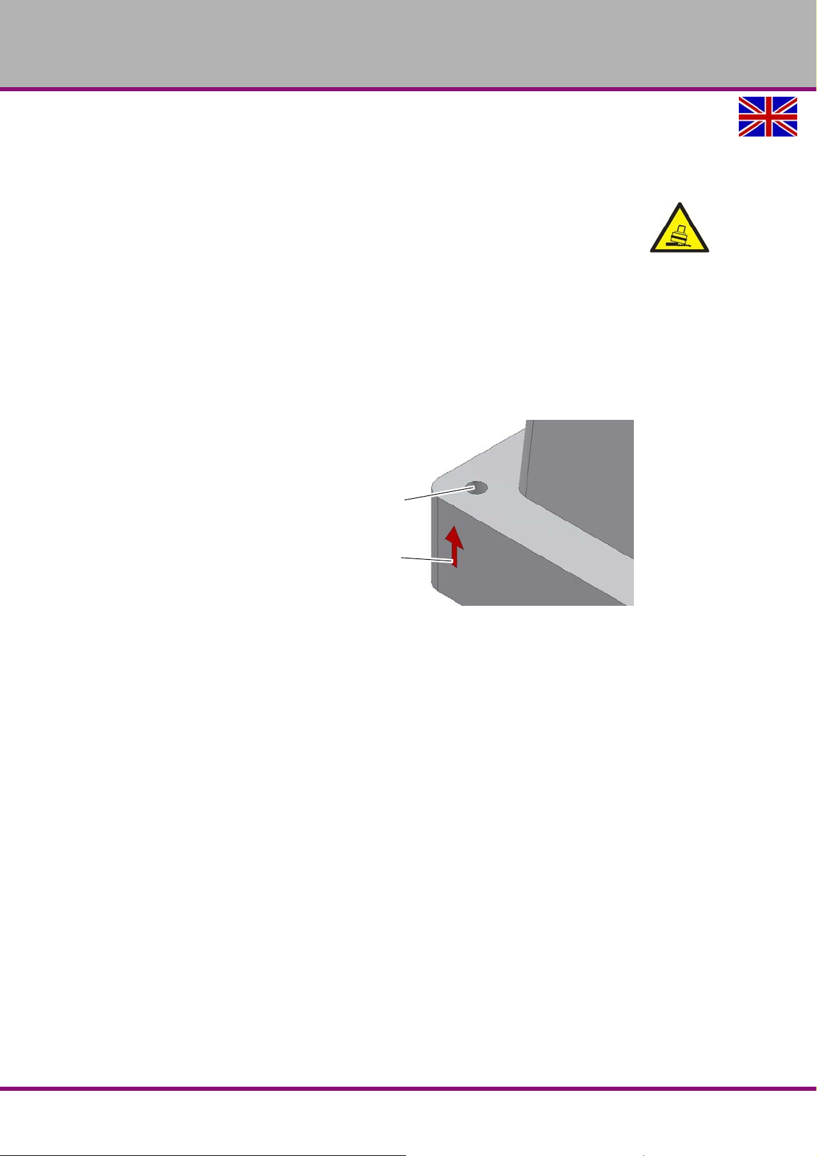
Fix the foot of the multi-milling
machine to the substructure with the
provided through-holes.
The through-bore are marked with
arrows on the machine base.
Img.3-2: Attachment points on machine foot
MF2V_3_GB.fm
MF2 VarioGB
Version 1.3.0 dated 2016-12-16Page 22 Translation of the original instructions
Page 25
OPTIMUM
736
1600
920
603
140
498
16
Fixing bolts
MASCHINEN - GERMANY
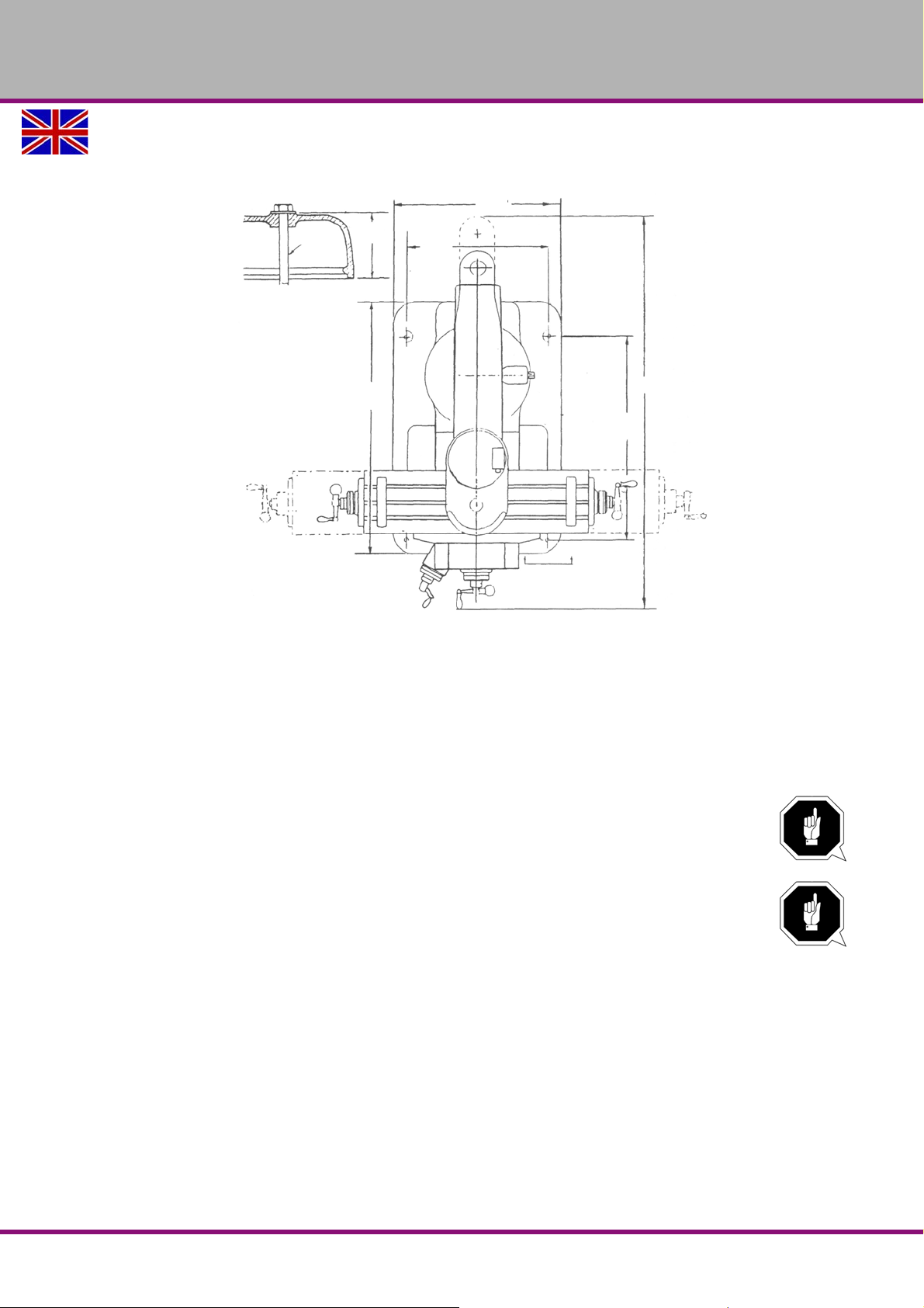
The multi-milling machine is fixed to the floor by four anchor screws whi ch are past th rough the
machine foot. The dimensions for the anchoring bolts can be seen in the following drawing.
Img.3-3: Anchoring dimensions
Prepare level installation place and the anchoring bolts.
Lift the multi-milling machine and position them above the anchoring bolts.
Carefully lower the multi-milling machine, the anchoring bolts must be introduced through
the holes in the machine foot.
Install washers and nuts on the anchoring bolts.
Check that the multi-milling machine is horizontal using a spirit level on the cross table and
put wedges under the machine foot if necessary.
ATTENTION!
All four corners of the machine foot must lie flat.
Tighten the nuts of the anchoring bolts.
ATTENTION!
If the fixing screws are too tight in particular in connection with an uneven substructure
it may result in a broken stand of the multi-milling machine.
Check the alignment of the multi-milling machine again.
MF2V_3_GB.fm
Version 1.3.0 dated 2016-12-16 Page 23Translation of the original instructions
MF2 Vario GB
Page 26
OPTIMUM
MASCHINEN - GERMANY
3.6 First commissioning
ATTENTION!
Before commissioning the machine, all bolts, fastenings and protections must be
checked and retightened as necessary!
WARNING!
The use of improper tool holders or their operation at inadmissible speeds constitutes a
hazard.
Only use the tool holders (e.g. drill chuck) which were delivered with the machine or
which are offered as optional equipment by OPTIMUM.
Only use tool holders in the intended admissible speed range.
Tool holders may only be modified in compliance with the recommendation of OPTIMUM
or of the manufacturer of the clamping devices.
WARNING!
First commissioned of the multi-milling machine by inexperienced personnel constitute
a risk to personnel and equipment.
We do not accept any liability for damages caused by incorrectly performed
commissioning.
„Qualification of personnel“ auf Seite 9
3.7 Warming up the machine
ATTENTION!
If the milling machine and in particular the milling spindle is immediately operated at
maximum load when it is cold it may result in damages.
If the machine is cold, e.g. directly after having transported the machine, it should be
warmed up at a spindle speed of only 500 1/min for the first 30 minutes.
3.8 Electrical connection
CAUTION!
Must only be worked on by a qualified electrician or person working under the
instructions and supervision of a qualified electrician. Arrange the machine's connection
cable in such a way that it will not cause a tripping hazard.
Ensure that all 3 phases (L1, L2, L3) and the ground wire are connected correctly.
The neutral conductor (N) of its power supply is not connected.
400V three - phase connection, correct direction of rotation, observe phase sequence!
If necessary, two phase connectors at the three phase current switch or at the connection in the
control cabinet must be exchanged. The guarantee will become null and void if the machine is
connected incorrectly.
Please check that the type of current, voltage and protection fuse correspond to the values
specified. A protective earth ground wire connection must be available.
Main Fuse 16A.
Observe the notes on the connection for machines with frequency converters.
MF2V_3_GB.fm
MF2 VarioGB
Version 1.3.0 dated 2016-12-16Page 24 Translation of the original instructions
Page 27

OPTIMUM
MASCHINEN - GERMANY
3.9 Electrical connection of machines with frequency converter
3.9.1 Regulated drives in connection with residual current devices
Speed-controlled drives are one of the st andard equipment in machine and plant constructio n
and perform various tasks. Compared to a simple motor, the elect ronic rectifiers or converters
require some special features for the necessary sa fety measures for el ectrical safety. Depe nding on the application, the use of a fault current protection device, differential current monitoring or insulation monitoring can make more sense.
For electrical safety, DIN VDE 0100-410 (VDE 0100 part 410): 1997-01 "Erection of heavy current installations up to 1000V" is a basic standard. It describes both, the admissible net forms
and the necessary protec tive measur es agai nst dangerous body currents. Based on this standard DIN EN 50178 (VDE 0160): 1998-04 "Equipping of heavy current systems with electronic
equipment" specifies the protective measures to be applied to controlled drives in more detail. It
calls for: "In the case of electronic equipment, the protection of persons against dangerous
body currents must be carried out in such a way that a single fault does not cause any danger ."
Regulated drives with residual current devices
The TN-S system is the most co mmon network fo rm for the operat ion of controlled drives. This
is done, among other things, for EMV reasons and to avoid vagabonding currents. In accordance with DIN VDE 0100-410 (VDE 0100-410): 1997-01, fault current protective devices
(ELCB) can be used as a protective measure against dangerous body currents. According to
DIN VDE 0100-482 (VDE 0100 part 482): 2003-06 "Electrical installations of buildings", cables
and wiring systems in fire-endangered plants must be protected by ELCBs with a rated differential current of 300 mA. According to IEC 60755, ELCBs differ in the type of fault currents they
can detect. In conjunction with electronic devices currents with DC components may occur.
3.9.2 Protection from Dangerous Shock Currents, use of ELCBs
To achieve increased safety in all installation systems, and in power supply ranges for which
the installation provisions stipulate or recommend the ELCB devices.
Measure for “Protection from Dangerous Shock Currents”, as regulated in DIN VDE 0100 Part
410. All measures are to be mentioned:
Protection from indir ect contact – as p rotection against fault by shutting down in the event of
inadmissibly high contact voltage by short circuit shock on the operating resource.
Protection from direct contact – as additional protection by shutting down in the event of
contact with a live conductor. Dangerous shock currents are shut down within the shortest
possible time, if the rated fault current of the circuit breaker is 30 mA, for a personal protection system 10 mA.
Fire prevention – Prevention of the origination of electrically-ignited fires if the rated fault
current of the circuit breaker is 300 mA. Operating premises at risk of fire to VdS 2033:
2002-02 300 mA.
3.9.3 Current in the protective earth conductor - Leakage current
With EMC filters in frequency converters, the leakage current is always greater than 3.5 mA
due to physics. Some types of frequency converters also achieve a leakage current of up to
300mA.
Therefore, a fixed earth connection is required and the minimum cross section of the protective
earthing conductor must conform to local safety regulations for devices with high leakage current. This is achieved by prov iding a permanent fixed earthing connection with two independent conductors, each having a cross section the same as the power supply cord or greater.
Preferably, machines with frequency converters are therefore to be permanently connected to a
terminal box, otherwise an additional fixed earth connection is required, which is not routed
over the plug, and must correspond to at least the cross-section of the cable in the plug.
Converter-plus-ELCB-plus-EMV_GB.fm
GB
Version 1.3.0 dated 2016-12-16 Page 25
Page 28
OPTIMUM
MASCHINEN - GERMANY
Since a direct current may be caused by the frequency converter in the protective earthing conductor, if an upstream residual current device (ELCB / RCD) is required in the network, the following guidelines must be followed:
To avoid an operating fault, you need an AC/DC-sensitive ELCB. Be absolutely sure
which leakage current security is necessary for dangerous body currents, as regulated
in DIN VDE 0100 part 410, at your mains connection.
3.9.4 When the ELCB triggers
Pulse current - sensitive ELCB type A
ELCB type A independent of rated voltage, for triggering when changing fault currents and pulsing DC fault currents.
AC/DC - sensitive ELCB type B
ELCBs of series type B also accept the detection of smooth AC fault currents as well as the detection of fault current shapes of type A; they are
therefore suitable for all the circuits mentioned. ELCBs of this series therefore detect all
types of fault current according to the triggering characteristic B, i.e. both smooth DC fault
currents and also all AC fault currents of all frequencies and mixed frequencies up to 1 MHz
are detected and switched off reliably in the event of a fault.
Alternating current - sensitive ELCBs of type AC (only alternating current) are
unsuitable for frequency converters. Alternating current - sensitive ELCBs of type
AC are not customarily used and are no longer permitted in Germany.
Type B must be used with 3-phase converters.
When using an external EMC filter, to avoid false er ror shutdowns, a time delay of at least 50
ms is required. The leakage current can exceed the threshold trigger value for an error shutdown if the phases are not switched on at the same time.
GB
Converter-plus-ELCB-plus-EMV_GB.fm
Version 1.3.0 dated 2016-12-16Page 26
Page 29
4 Operation
2
11
9
12
4
5
13
6
7
1
3
10
8
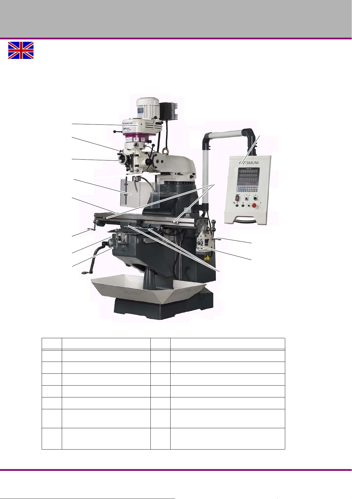
4.1 Overview
OPTIMUM
MASCHINEN - GERMANY
Pos. Designation Pos. Designation
1 Spindle head 8 Wheel for cross table (Y-axis)
2 Spindle sleeve lever 9 Control panel
3 Spindle sleeve fine feed 10 Stops
4 Spindle protection 11 Crank handle
5 Cross table 12 Control module for feed motor
6 Crank handle for cross table
(X-axis)
7 Tightening lever for cross table
Height adjustment
Img.4-1: Overview of the machine
13 Tightening lever for cross table (X-axis)
Version 1.3.0 dated 2016-12-16 Page 27Original operating instructions
MF2 Vario GB
Page 30
OPTIMUM
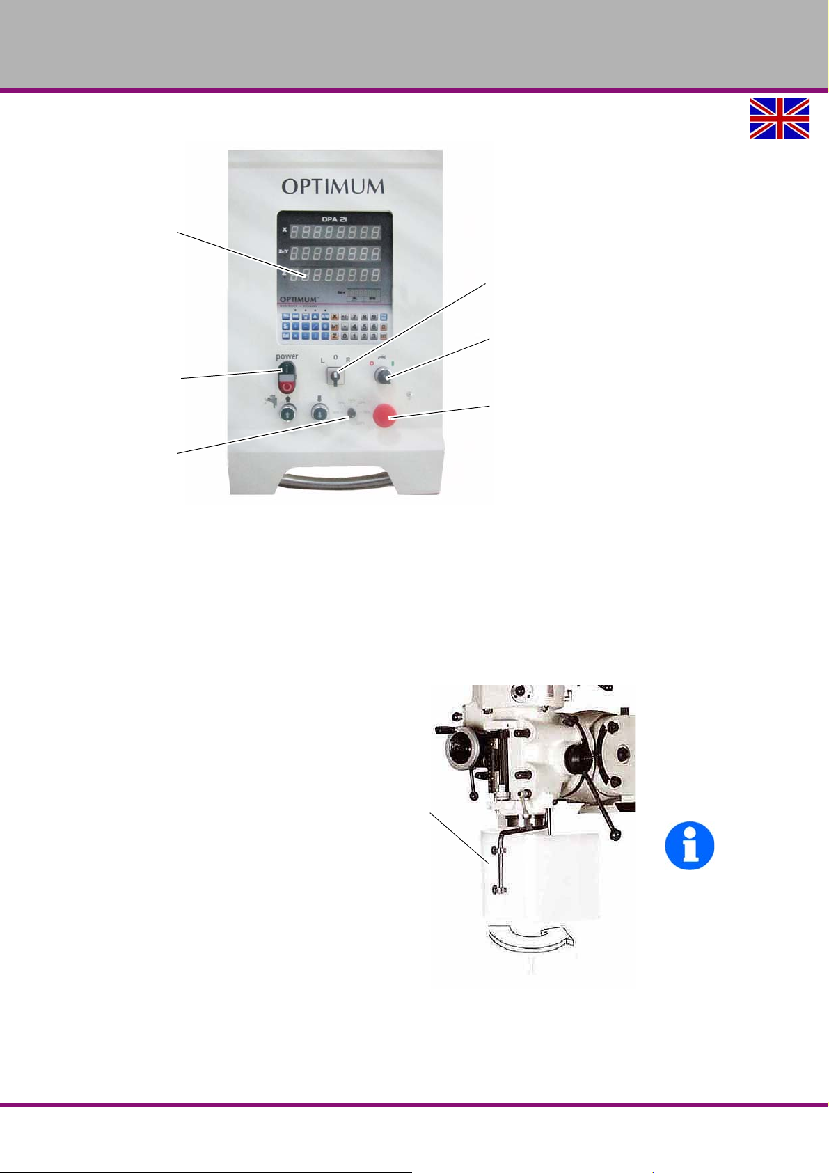
Digital position display
DPA 21
ON/OFF switch
Control panel
Speed control
Spindle
Spindle Left - Stop Right selector
ON/OFF switch
Cooling lubricant
EMERGENCY-STOP
button
Separating
protective
equipment
MASCHINEN - GERMANY
4.1.1 Control panel
4.1.2 Safety devices
The machine has the following safety devices:
EMERGENCY-STOP push button
a separating protective device on the milling spindle,
4.1.3 Separating protective equipment
Adjust the protective equipment to the
correct height before you start working.
To do so, detach the clamping screw,
adjust the required height and re-tighten
the clamping screw.
A switch is integrated in the fixture of the
spindle protection which monitors that
the cover is closed.
INFORMATION
You cannot start the machine if the spindle protection is not closed.
Img.4-2: Control panel
MF2 VarioGB
Img.4-3: Separating protective equipment
Version 1.3.0 dated 2016-12-16Page 28 Original operating instructions
Page 31
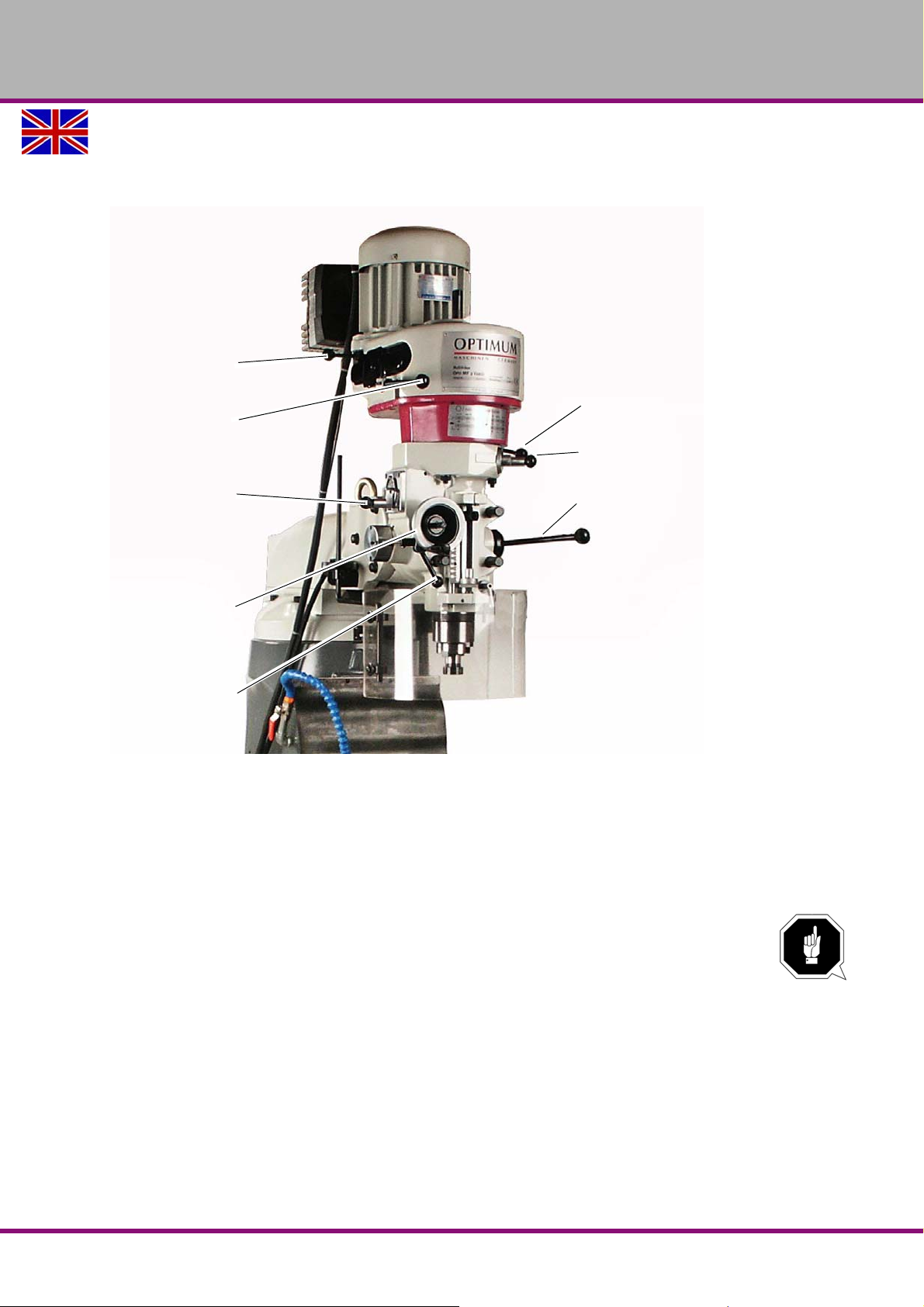
4.2 Design of the multi-milling machine MF2 Vario
Motor clamping lever
Spindle brake
Selector switch
spindle sleeve feed
speed
Hand wheel
spindle sleeve fine
feed
Lever
Drill depth stop
Gear switch
Spindle sleeve feed
ON/OFF switch
Lever for spindle
sleeve feed (manual)
4.2.1 Spindle head
OPTIMUM
MASCHINEN - GERMANY
Img.4-4: Spindle head
4.2.2 Switch cabinet
The switch cabinet is located on the right-hand side of the machine and has a lock.
It contains all the fuses and the wiring diagram. The main switch is located on the outside of the
switch cabinet.
ATTENTION!
Operational personnel do not have access to the distribution cabinets.
Switch Cabinets should only be opened by maintenance personnel.
4.2.3 Coolant pump
The cooling lubricant pump is located inside the machine. It can be accessed through the ventilation panel at the back of the machine.
Version 1.3.0 dated 2016-12-16 Page 29Original operating instructions
MF2 Vario GB
Page 32
OPTIMUM
MASCHINEN - GERMANY
4.3 Safety
Use the multi-milling machine only under the following conditions:
During operation
The multi milling-machine is in proper working order.
The multi-milling machine is used as prescribed.
The operating manual is followed.
All safety devices are installed and activated.
Stop the machine immediately in the event of any abnormality in operation and make sure it
cannot be started up accidentally or without authorisation.
Notify the person responsible immediately of any modification.
ATTENTION!
Protect your eyes from chips and other splinters flying off at high speed. Use protective
goggles.
ATTENTION!
Noise levels may vary depending on the work cycle. Use ear protection!
4.3.1 Warming up the machine
ATTENTION!
If the multi- milling machine and in particul ar the milling spin dle is immedia tely oper ated
at maximum load when it is cold it may result in damages.
4.4 Switching the machine on and off
4.4.1 Switch on
Turn the main switch to the "On" position (see Img.4-5:).
The main switch is located on the distribution cabinet.
Press the "I" button on the control panel.
(The R/L selector must be set to 0. See Img.4-2:.
4.4.2 Switching off
Turn the On/Off switch on the control panel to the "Off" position.
Switch the main switch to the position „OFF“ / 0 , lock if necessary.
4.4.3 Locking the main switch
Place the red lock in the position shown in the figure by pressing on the left-hand side.
Only possible in the "Off" position
Place the padlock in the hole and lock it.
MF2 VarioGB
Version 1.3.0 dated 2016-12-16Page 30 Original operating instructions
Page 33
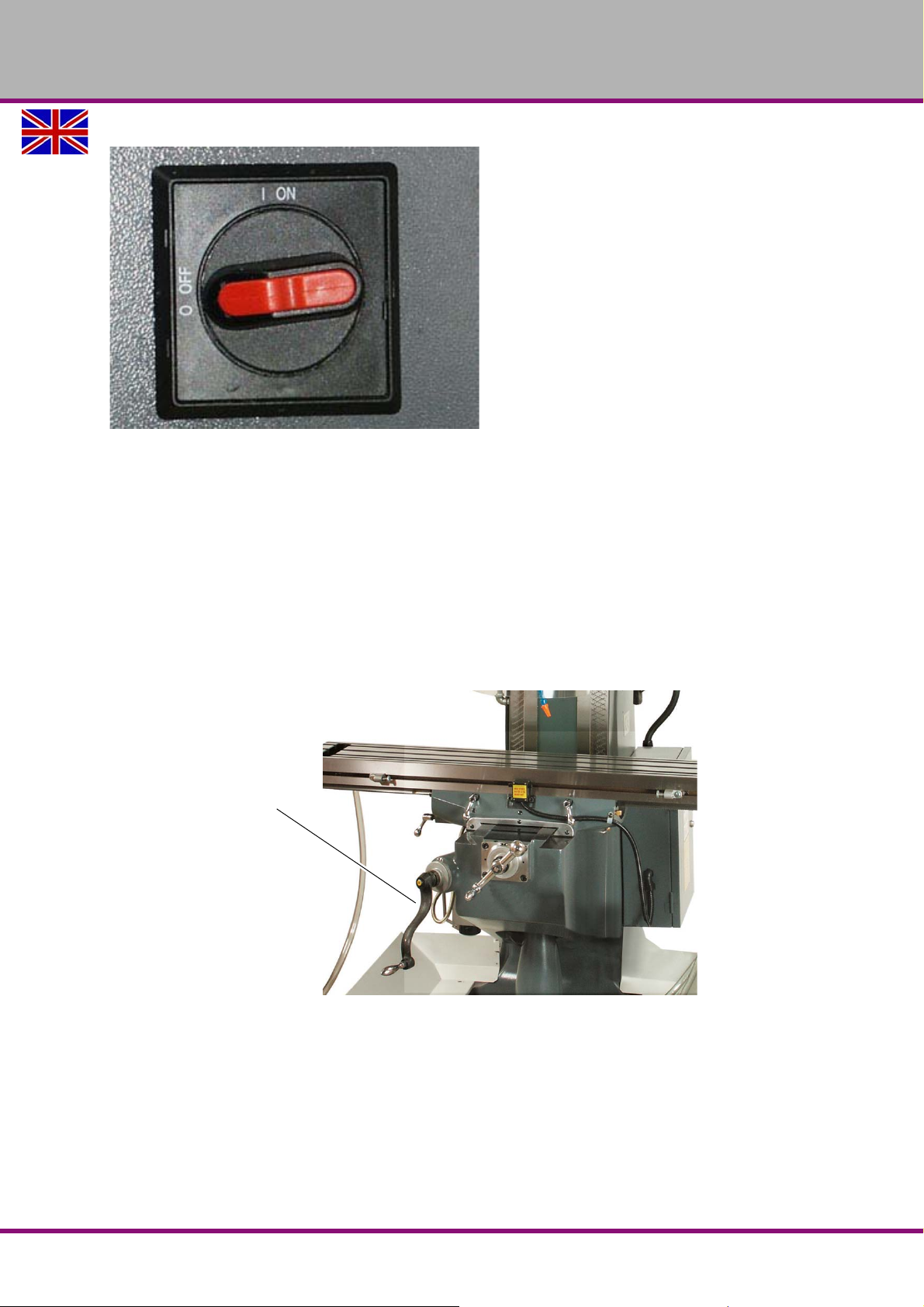
OPTIMUM
Crank handle
MASCHINEN - GERMANY
Img.4-5: Main switch
4.5 Raising / lowering the cross table
You can raise or lower the cross table using the crank handle.
Loosen the tightening lever.
Engage the handle by pushing it towards the teeth.
Turn the handle to the required position for the cross table.
The scale has a graduation of 0.2 mm. The zero point can be adjusted using the knurled
nut.
Clamp if needed.
Make sure to tighten the tightening lever again once you have completed the operation.
Img.4-6: Cross table - height adjustment
Version 1.3.0 dated 2016-12-16 Page 31Original operating instructions
MF2 Vario GB
Page 34
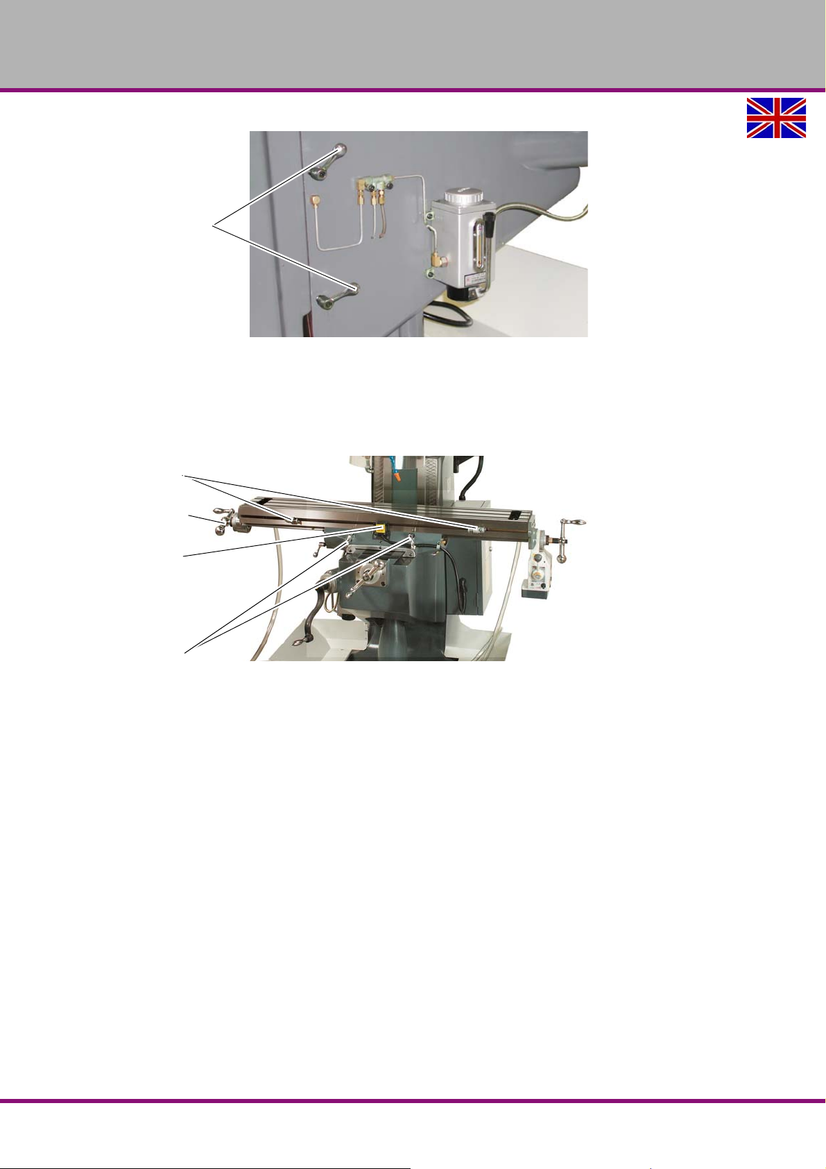
OPTIMUM
Clamping lever
End stops
Hand wheel
End switch
Clamping lever
MASCHINEN - GERMANY
Img.4-7: Clamping lever
4.6 Moving the cross table left or right (X-axis)
There are two ways of moving the cross table on the X axis.
by turning the hand wheels 4 on the right or left of the table.
Using the automatic feed motor.
Img.4-8: Moving the cross table on the X-axis
4.6.1 Manual movement on the X axis
Loosen the tightening lever.
Engage the crank handle by pushing it towards the clutch.
Turn the handle to the required position for the cross table.
The scale has a graduation of 0.2 mm. The zero point can be adjusted using the knurled
nut.
Make sure to tighten it again in the required position.
MF2 VarioGB
Version 1.3.0 dated 2016-12-16Page 32 Original operating instructions
Page 35
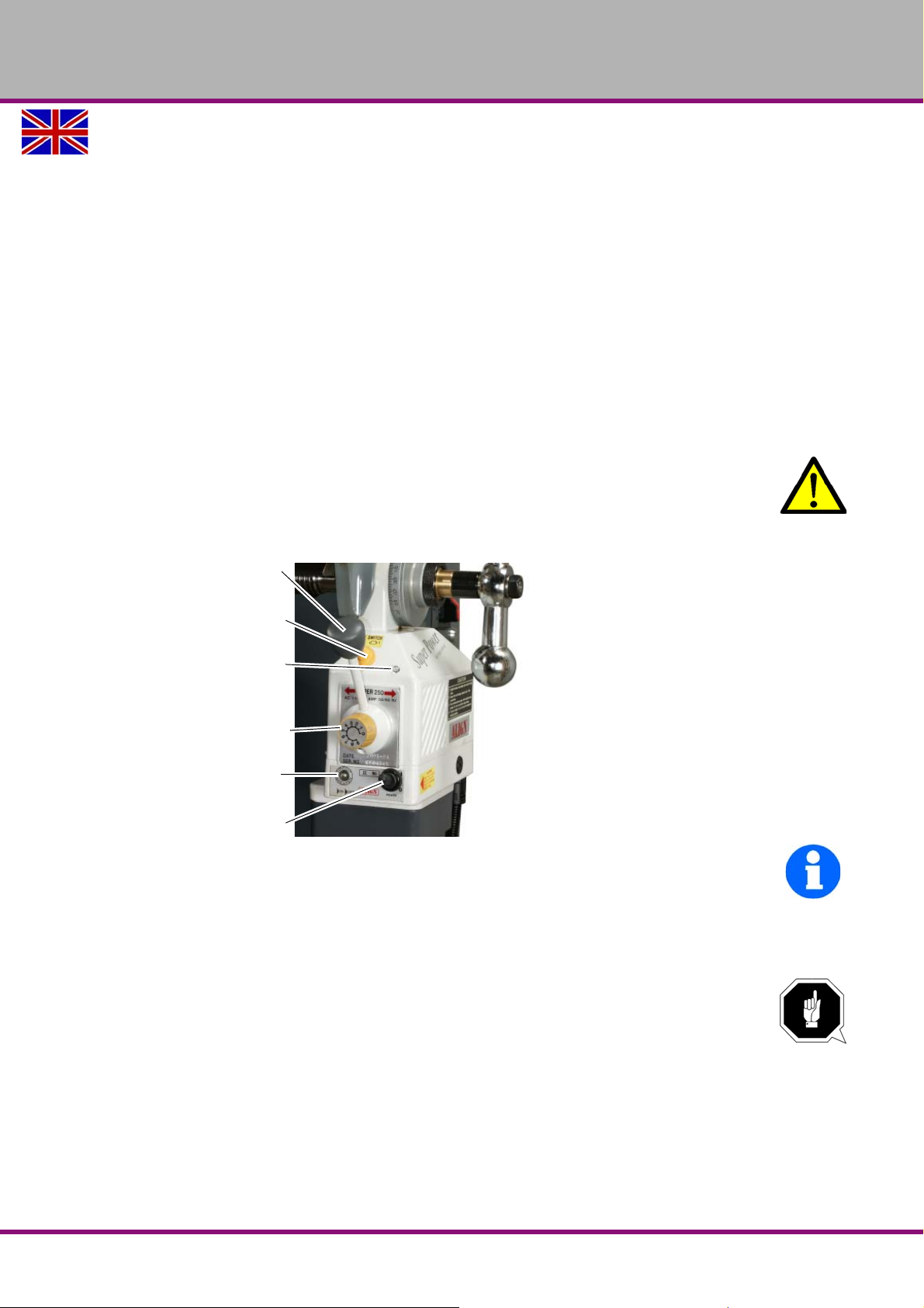
OPTIMUM
Direction lever
Fast motion
Operation control light
Speed regulator
Safety switch
ON/OFF switch
MASCHINEN - GERMANY
4.6.2 Automatic movement of the X-axis using the feed motor
The feed motor automatically moves the cross table along the X-axis.
Turn on the switch.
The service light comes on.
Adjust the feed speed using the speed regulator.
Move the direction lever to the direction in which you want the cross table to move.
When the lever is in the central position, the feed motor is halted.
Do not change the motor from L to R during the operation.Wait until it has come to a com-
plete halt.
The end stop switch and th e two adjustable stops deactivate the automatic feed when the
preset position is reached.
Move the turning direction lever in the required direction.
Press the button for fast motion.
Once you release the button the machine will proceed at the preset speed.
WARNING!
When the feed motor is operating in fast motion, do not touch moving parts or rotating
parts.
Make sure there are no other people in the danger zone.
INFORMATION
The circuit is automatically disc onnected if a cu rrent of 4 A circul ates through the safety switch
for more than 10 seconds.
To reactivate it, press the safety switch for a moment.
The service light will come on again.
ATTENTION!
During manual operation the li mit stops may collide with the end sto p switch. This can
cause damage to the end stop switch.
4.7 Moving the cross table forward / back (Y-axis)
The cross table may be mo ved on the Y axis using the hand wheel, located at the front of
the machine.
Loosen the tightening lever.
Engage the handle by pushing it towards the clutch.
Turn the handle to the required position for the cross table.
Version 1.3.0 dated 2016-12-16 Page 33Original operating instructions
MF2 Vario GB
Page 36
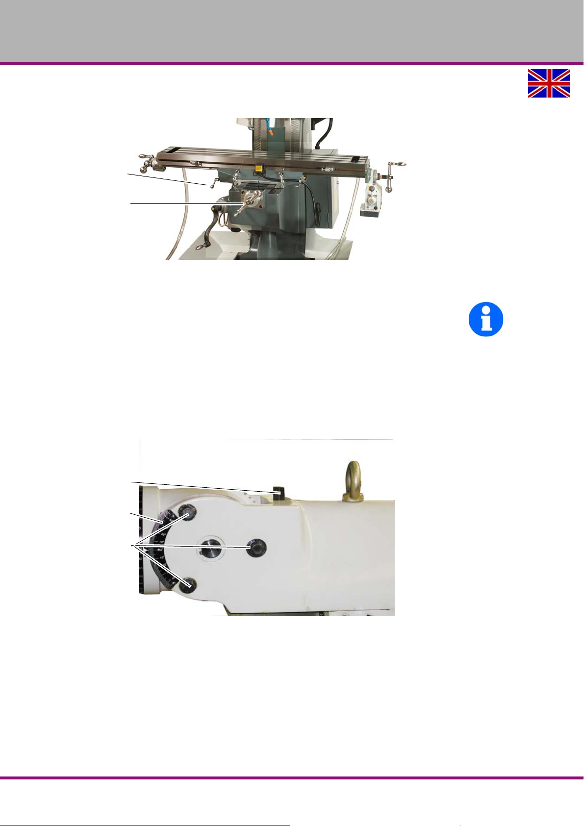
OPTIMUM
Clamping lever
Hand wheel
Movement screw
Scale ± 45°
Clamping screws
MASCHINEN - GERMANY
The scale has a precision of 0.2 mm. The zero point can be adjusted using the knurled nut.
Make sure to tighten it again in the required position.
Img.4-9: Moving the cross table to the Y-direction
4.8 Inclining the spindle head up or down
INFORMATION
Use a 17/19 polygonal spanner for the clamping screws and movement screws. One is
included among the accessories.
The spindle head can be inclined forward and back 45°.
Proceed as follows:
Loosen the clamping screws (3 units) located on the spindle head-holder.
Position the spindle head in the required position by screwing in or out the movement
screw.
You must re-tighten the clamping screws.
MF2 VarioGB
Img.4-10: Inclining the spindle head up or down
Version 1.3.0 dated 2016-12-16Page 34 Original operating instructions
Page 37
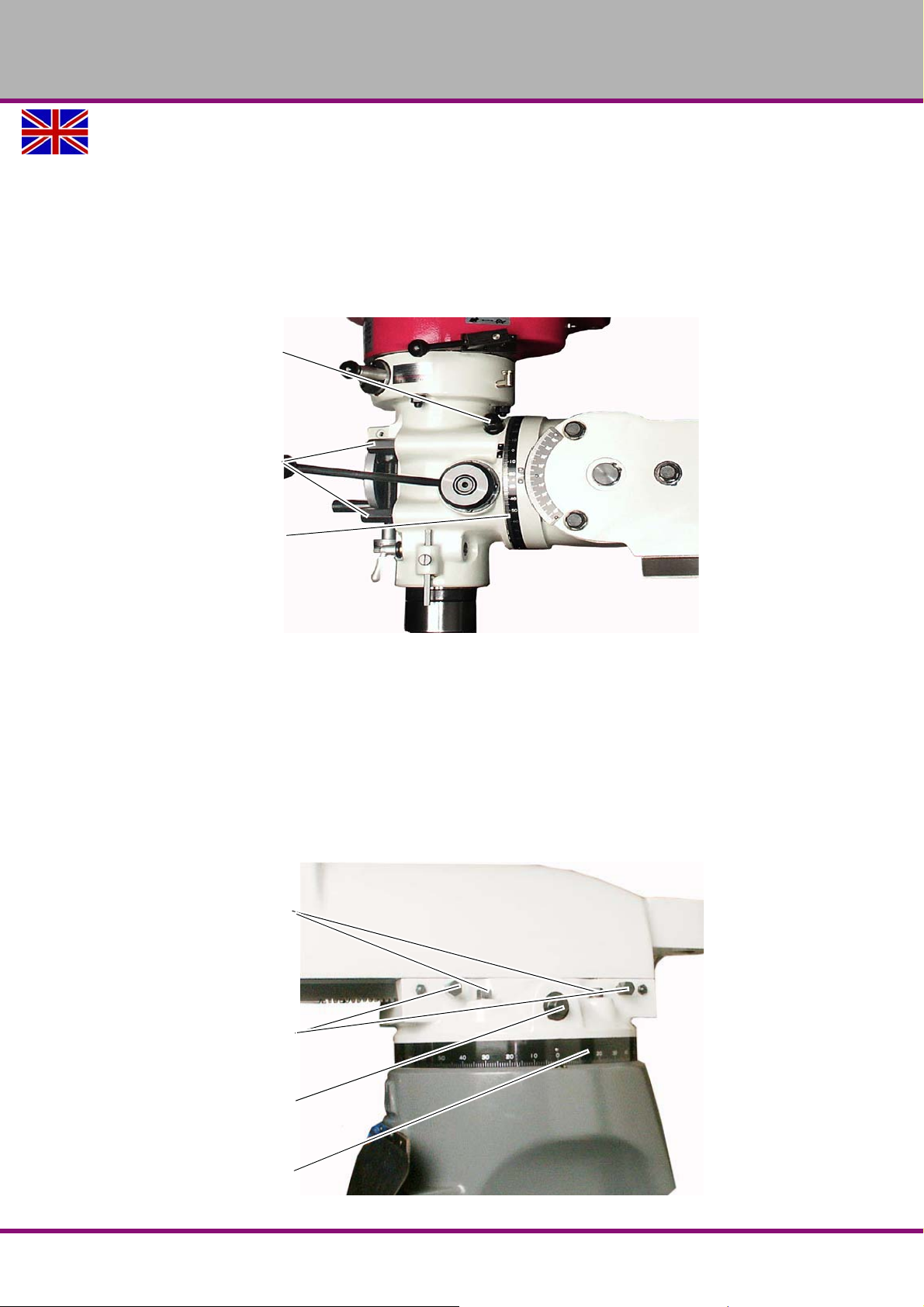
OPTIMUM
Movement screw
Clamping screws
Scale ± 90°
Clamping screws for moving the
spindle head-holder
back and forward
Clamping screws for turning
the spindle head-holder
Movement screw for moving the
spindle head-holder back and
forward
back and forward
± 90º scale for turning the
spindle head-holder
MASCHINEN - GERMANY
4.9 Orienting the spindle head to the right or left
The spindle head can be oriented 90° to the right or left.
Proceed as follows:
Loosen the clamping screws (4 units).
Position the spindle head in the required position by screwing in or out the movement
screw.
Imperatively fasten the clamping screws.
4.10 Moving the spindle head-holder forward or back
You can move the spindle head-holder forward or back.
Proceed as follows:
Loosen the clamping screws (2 units).
Position the spindle head-holder in the required position by screwing in or out the move-
ment screw.
Imperatively fasten the clamping screws.
Img.4-11: Moving the spindle head to the right or left
Version 1.3.0 dated 2016-12-16 Page 35Original operating instructions
Img.4-12: Moving the spindle head-holder forward or back
MF2 Vario GB
Page 38
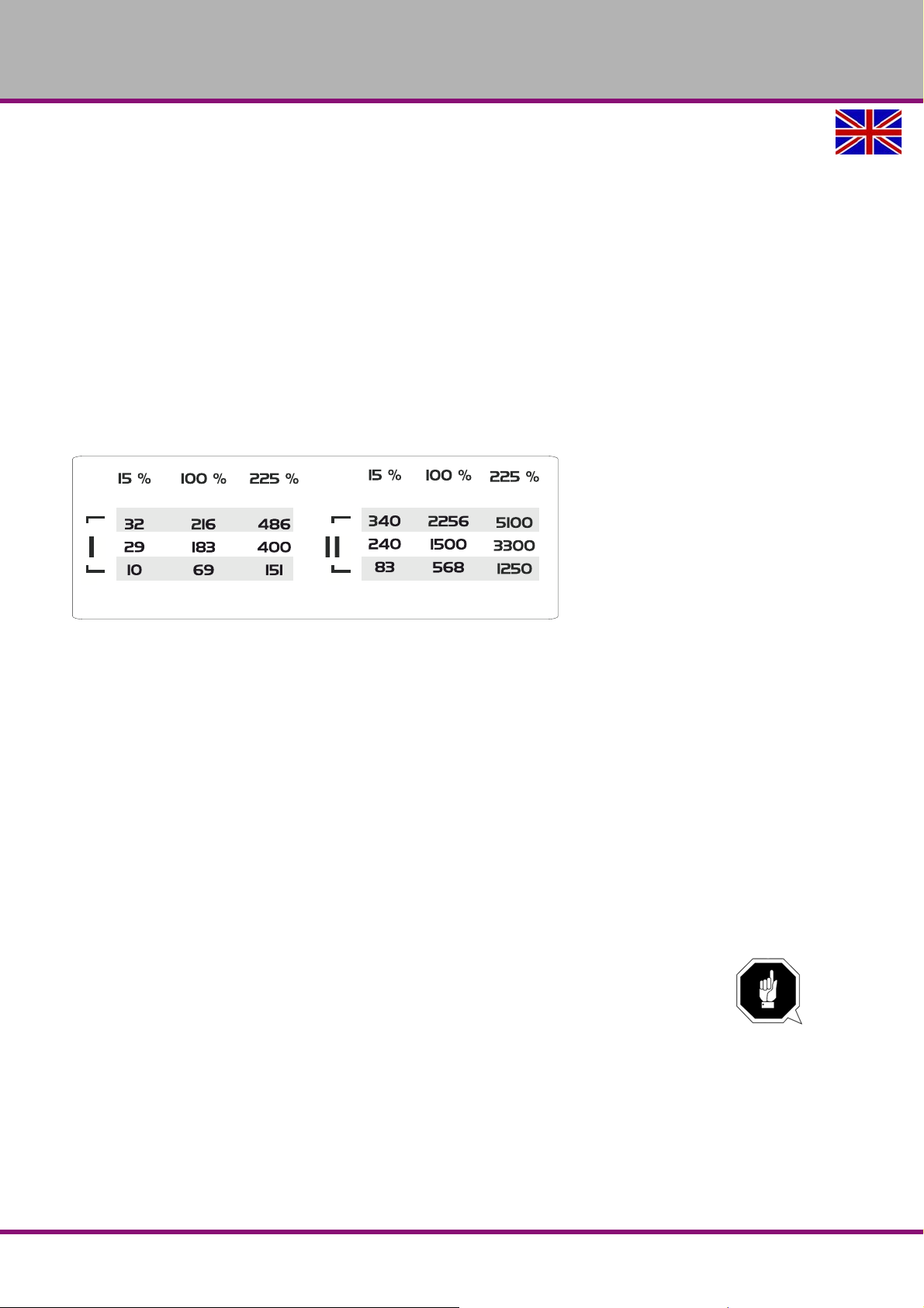
OPTIMUM
MASCHINEN - GERMANY
4.11 Turning the spindle head-holder
You can turn the spindle head-holder 90°.
Proceed as follows:
Loosen the clamping screws (4 pieces).
Turn the spindle head carrier to the required pos i tion .
Fasten the clamping screws.
4.12 Adjusting the spindle speed
There are three ways of adjusting the speed of the spindle:
via the pulleys of the intermediate gear
on the gear switch
by fine adjustment of the motor speed
The spindle can be set to the following speeds:
Img.4-13: Spindle speeds
4.13 Pulleys
The speed of the spindle can be adjusted using the 3 grooves on the pulleys.
If the V-belt is positioned in the upper pulley, the spindle turns at maximum speed.
When the V-belt is in the bottom pulley, the spindle turns at minimum speed.
In order to move the belt from one pulley to another you will need to
switch off the main switch of the machine and ensure that it cannot be switched on again.
remove the protective pulley cover located on the spindle head.
loosen the two motor tightening levers (Img.4-12:Spindle head),
move the motor with the aid of the handle until the belts are loose,
place the belt in the required groove,
move the motor back so that the belt is tight again,
re-tighten the two motor tightening levers.
ATTENTION!
Check the tension in the V-belt.
The tension in the V-belt is correct if you can push it approximately 5 mm with your
finger.
Imperatively reassemble protective covers.
MF2 VarioGB
Version 1.3.0 dated 2016-12-16Page 36 Original operating instructions
Page 39
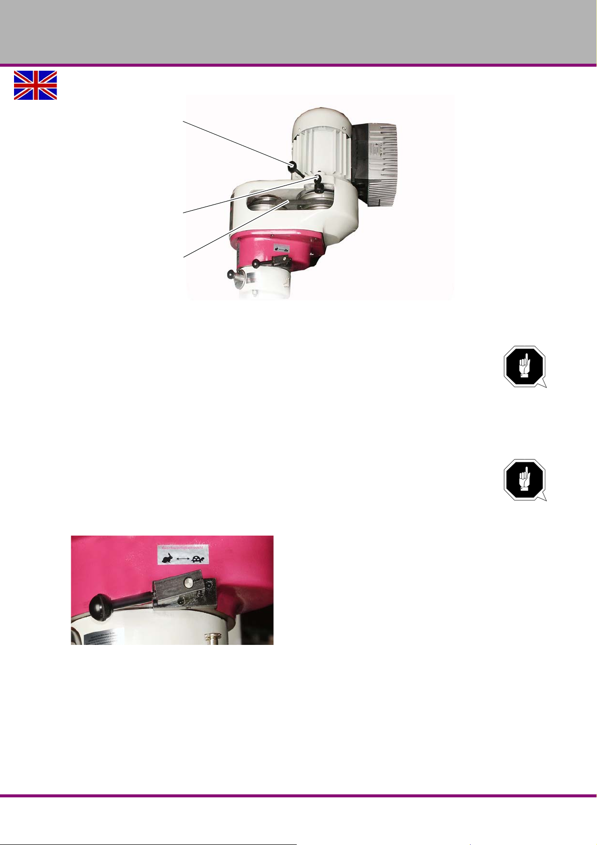
4.13.1 Gear switch
Handle for the
motor displacement
Motor clamping
lever
(2 units)
V-belt
OPTIMUM
MASCHINEN - GERMANY
Img.4-14: Adjusting the speed of the spindle using the belts (with the protective cover removed)
ATTENTION!
The selector must only be activated when the motor is stopped.
To help change the positions of the selector, turn the spindle by hand.
The gear selector is located on the spindle head. The following speeds can be selected:
high speed (horizontal lever to the left (hare symbol)
neutral (lever in the centre)
low speed (horizontal lever to the right / tortoise symbol))
ATTENTION!
When changing over the gear selector to high or low speed, the turning direction of the
spindle is changed too.
If you want to keep the turning direction, change the turning direction on the control
panel (with the
"Spindle Left - Stop - Right selector“ on page 38).
Img.4-15: Gear-switches into non locked in place neutral position
For high or low speed, the lever must be in horizontal position and engaged.
After setting the required running mode, the spindle sleeve must be withdrawn a few milli-
metres to engage the gear.
Version 1.3.0 dated 2016-12-16 Page 37Original operating instructions
MF2 Vario GB
Page 40
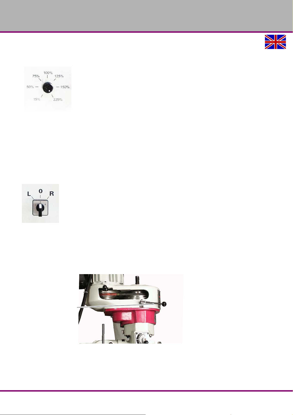
OPTIMUM
Spindle brake
MASCHINEN - GERMANY
4.13.2 Fine adjustment of the motor speed
The motor speed can be set from the control panel. The speed can be varied from 15 to 225%.
Img.4-16: Spindle motor speed control
4.14 Spindle Left - Stop - Right selector
The selector can be used to
activate and deactivate the main spindle
change the turning direction of the spindle
L = Turning direction: Left
R = Turning direction: Right
0 = Deactivate spindle
Img.4-17: Spindle Left - Stop - Right selector
4.15 Spindle brake
The spindle brake is located on the left-hand side of the spindle head. It is used to brake the
spindle.
When th e spindle brake is activated, the spindle slows down immediately.
The more the lever is activated, the more the spindle slows down.
Img.4-18: Spindle brake
4.16 Drill depth stop
The drill depth can be set using the set nut.
Turn the set nut till the required drill depth is aligned with the depth scale.
The spindle can now only be lowered to the set depth.
MF2 VarioGB
Version 1.3.0 dated 2016-12-16Page 38 Original operating instructions
Page 41
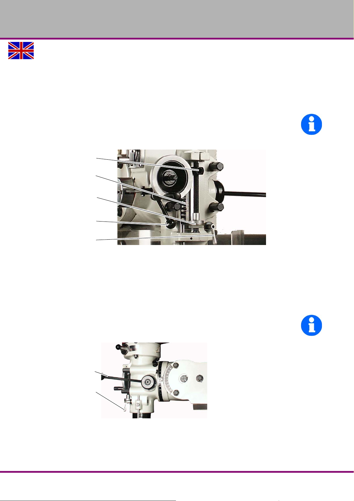
OPTIMUM
Stop
Depth scale
Set nut with
measurement indicator
Operating lever for
reduction connection
Clamping lever for
spindle sleeve
Spindle sleeve lever
Spindle sleeve tighten-
ing lever
MASCHINEN - GERMANY
There is an end stop for working with automatic spindle sleeve feed.
4.16.1 End stop operating lever
Loosen the tightening lever for the spindle sleeve.
Move the lever to the left to activate the end stop.
The end stop will remain activated until the spindle stop comes into contact with the set nut
or until the lever is manually disengaged.
INFORMATION
When the pre-set drill depth is reached, the activated end stop deactivates the automatic spindle sleeve feed.
Img.4-19: Drill depth stop
4.17 Spindle sleeve feed
Spindle sleeve feed can be manual or automatic.
4.17.1 Manual spindle sleeve feed
Activate the spindle sleeve lever to raise or lower the spindle sleeve by hand
You can set the spindle sleeve to a given height using the tightening lever.
INFORMATION
For all movements you must first loosen the tightening lever!
Img.4-20: Spindle sleeve lever
Turn the hand wheel for fine adjustment.
Version 1.3.0 dated 2016-12-16 Page 39Original operating instructions
MF2 Vario GB
Page 42
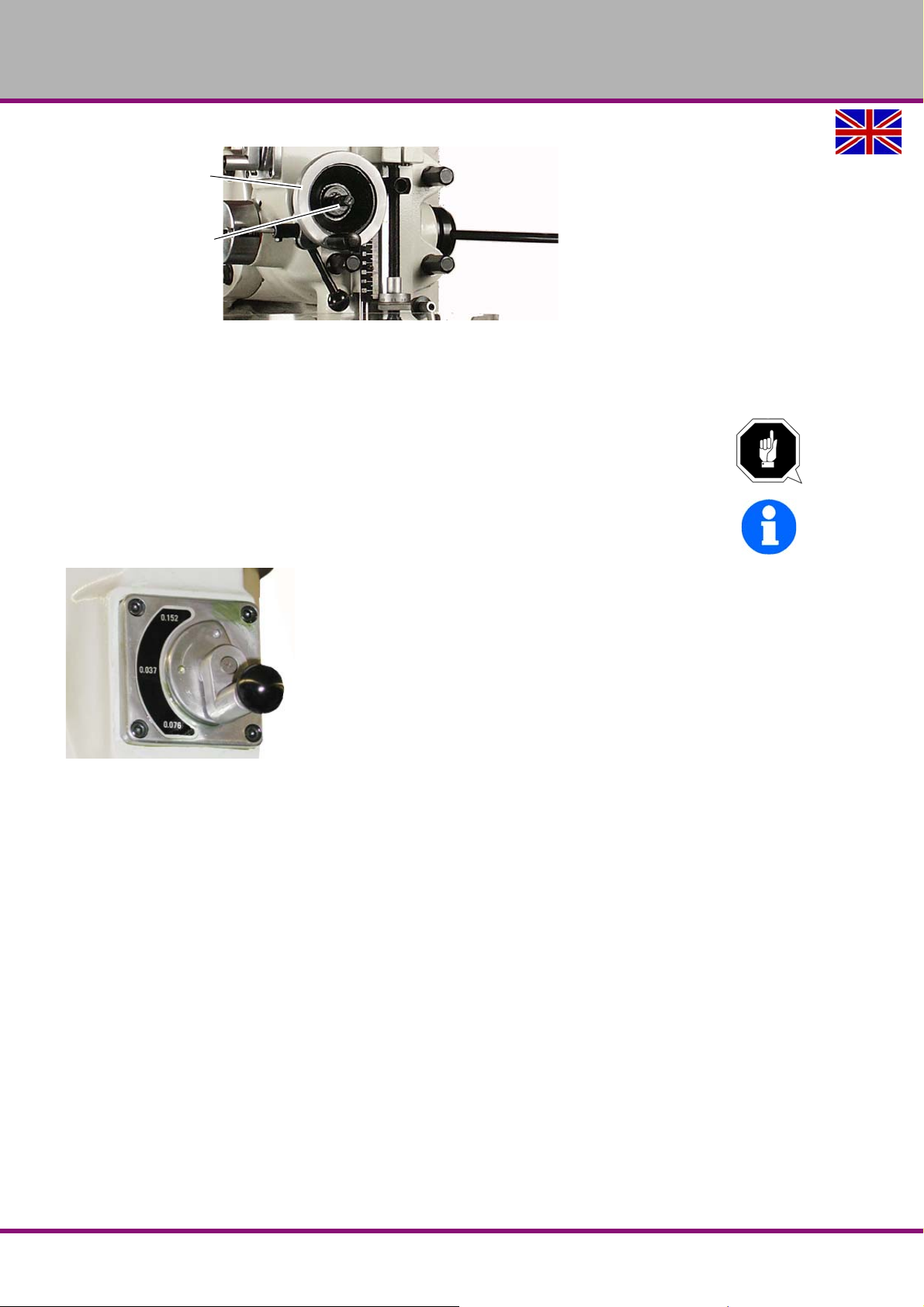
OPTIMUM
Hand wheel
Feed reverse mode
button
MASCHINEN - GERMANY
Img.4-21: Handwheel for fine adjustment
4.17.2 Automatic spindle sleeve feed
The automatic spindle sleeve feed is linked to the speed of the spindle.
ATTENTION!
Stop the motor before connecting the automatic spindle sleeve feed.
After use, disconnect the automatic spindle sleeve feed.
INFORMATION
Raising and lowering the spindle with the hand wheel makes it easier to rotate the lever.
Img.4-22: Selector switch - Spindle sleeve feed speed
To select the speed of feed of the spindle sleeve using the selector, proceed as follows:
Pull out the round knob.
Turn the lever to the required speed.
Release and engage the round knob in that position.
The following feeds are available:
0.152 mm per revolution of the spindle
0.037 mm per revolution of the spindle
0.076 mm per revolution of the spindle
Once you have chosen the speed of the spindle sleeve, you can turn on the switch for the automatic spindle sleeve feed.
MF2 VarioGB
Version 1.3.0 dated 2016-12-16Page 40 Original operating instructions
Page 43
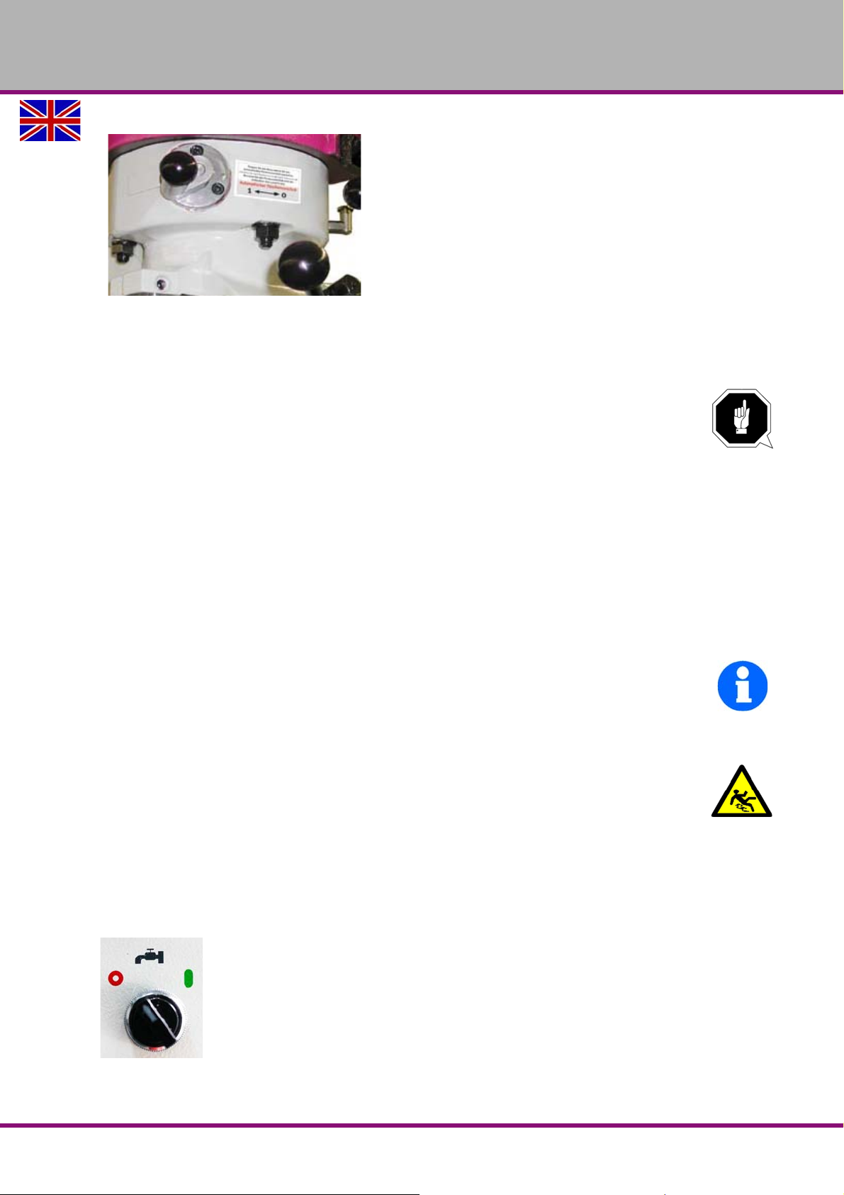
OPTIMUM
MASCHINEN - GERMANY
Img.4-23: On / Off switch for spindle sleeve feed speed
Pull out the round knob.
Move the automatic spindle sleeve feed to the "1" position.
Release and engage the round knob.
ATTENTION!
Never use the spindle sleeve feed at turning speeds of over 2,700 rpm.
4.17.3 Feed reverse button
In the centre of the fine feed hand wheel there is a button for reversing the feed direction. (See
Img.4-21: Handwheel for fine adjustment.)
Because the spindle sleeve feed is linked to the turning direction of the spindle, the feed direction changes with the turning direction of the spindle.
For a downward feed, proceed as follows:
If you are workin g with a clockwise tool, you should pull out the button until the clutch
engages.
If you are working with an anti-clockwise tool, push the button in.
The neutral position is located between the forward and reverse positions.
INFORMATION
If you are not using manual fine adjustment, leav e the reverse button in the neutral position.
4.18 Cooling agent
WARNING!
Ejection and overflowing of coolants and lubricants. Make sure you do not get the
cooling lubricants on the floor. Spilled on the floor cooling agents must be removed
immediately.
The flow of cooling agent is activated and deactivated by means of a selector with on the control panel
0 = Deactivate cooling agent feed
1 = Activate cooling agent feed
Img.4-24: Cooling agent selector switch
The amount of cooling agent can be regulated using the dosing tap.
Version 1.3.0 dated 2016-12-16 Page 41Original operating instructions
MF2 Vario GB
Page 44
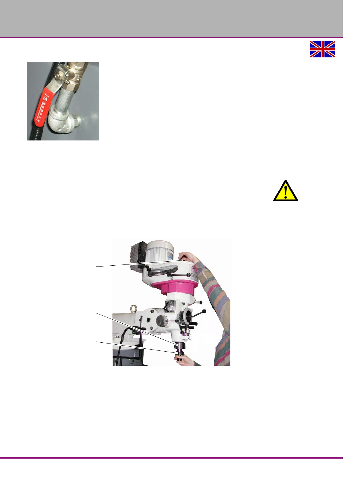
OPTIMUM
Draw-in rod
Spindle sleeve
Tool cone
MASCHINEN - GERMANY
This is located on the left-hand side of the machine.
Img.4-25: Dosing tap
4.19 Tool change
4.19.1 Installation
WARNING!
Disconnect the machine and ensure that it cannot be switched on again .
Clean the grip cone in the spindle sleeve and the tool cone before inserting the tool.
Insert the tool cone into the spindle sleeve.
The tenons on the spindle sleeve must sink into both grooves on the tool-holder.
Screw the draw-in rod in firmly.
Img.4-26: Fitting the tool
4.19.2 Disassembly
Release the thread of the draw-in rod.
You can immobilise the spindle during the unfitting process by activating the spindle brake.
Remove tool.
Possibly remove the tool with slide impacts of a rubber mallet on the draw-in rod from the
taper of the sleeve.
MF2 VarioGB
Version 1.3.0 dated 2016-12-16Page 42 Original operating instructions
Page 45
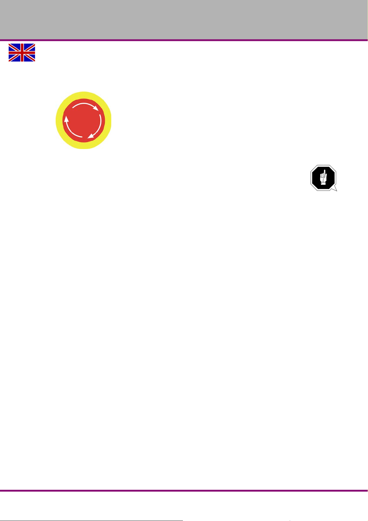
OPTIMUM
MASCHINEN - GERMANY
4.20 Stopping the machine in the event of an emergency
4.20.1 Position of the emergency stop knob
The EMERGENCY-STOP push button is located on the control panel.
Img.4-27: Emergency switch
ATTENTION!
The EMERGENCY-STOP push button stops the machine the moment it is activated.
Activate the emergency stop impact switch only in case of danger!
Unlock the emergency stop impact switch by turning.
Version 1.3.0 dated 2016-12-16 Page 43Original operating instructions
MF2 Vario GB
Page 46
OPTIMUM
MASCHINEN - GERMANY
5 Cleaning, maintenance, repair
Properly-performed regular maintenance, cleaning and repair is an essential prerequisite for
safe operation, fault-free operation, a long service life of the multi-milling machine and the quality of the products manufactured with it.
5.1 Safety
WARNING!
The consequences of incorrect maintenance and repair work may include:
Very serious injury to personnel working on the multi-milling machine,
damage to the multi-milling machine.
Only qualified personnel should carry out maintenance and repair work on the multimilling machine.
5.1.1 Measures before repair works
Switch off the machine according to these operating instructions and secure it against unex-
pected switching on again.
Disconnect the machine from the power supply.
5.1.2 Notes for repair
Observe maintenance dates and activities which ar e pr es cr ibe d in th e oper at ing instr u c-
tions.
Observe the procedures of switching on and off which are described in the operating
instructions.
A shop equipment suitable for performing repair measures is required.
5.1.3 Measures before switching on again and after repair measures
Before restarting run a safety check.
There must be no dangers for persons.
The multi-milling machine must not be damaged.
5.2 Cleaning
WARNING!
Only perform cleaning works when the machine is switched off.
Do not use petrol, thinner or compressed air for cleaning tasks.
Take every day after work clamping and workpiece from the table and table cleaning.
For rough cleaning tasks use a chip hook, a hand brush, vacuum cleaner or slot cleaner.
Remove solings and remaining lubricants with kerosene or special cleaning agents.
afterwards lightly lubricate blank surfaces.
MF2 VarioGB
Version 1.3.0 dated 2016-12-16Page 44 Original operating instructions
Page 47
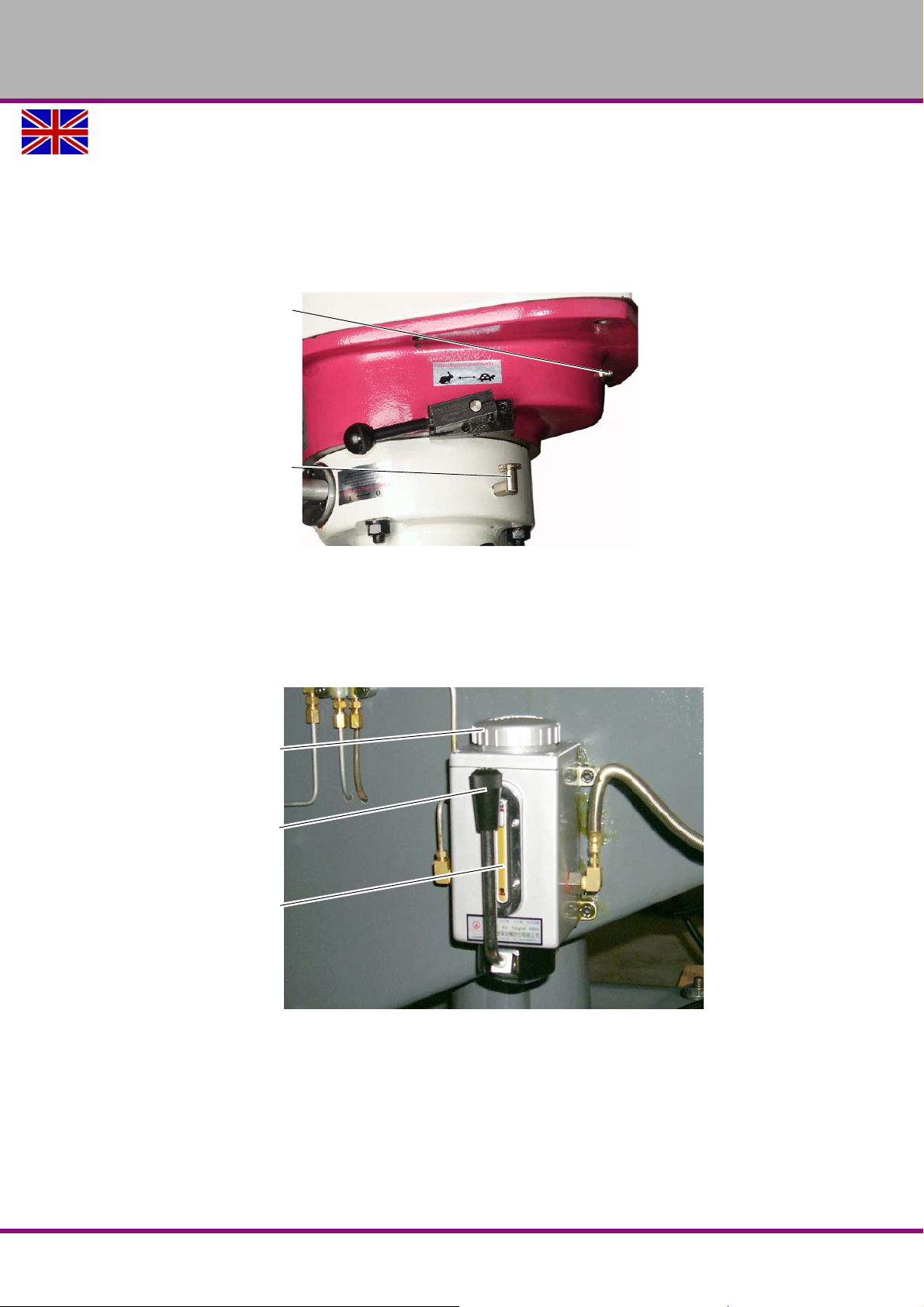
OPTIMUM
Lubricating nipple
Oiler cup
Lid
Lever
Sight glass
MASCHINEN - GERMANY
5.3 Lubricating
The multi-milling machine is equipped with a central lubrication system. This oils most greasing
points.
Fill quill oil in the oiler. (machine oil 628 Mobil)
Lubricate lubricating nipples using ball bearing grease.
every day
Img.5-1: Quill oiler
Activate the central lubrication system (Abbildung 5-2 ) using the lever. One stroke per
operating hour.
Refill central lubrication system, if required. Loosen lid and fill in machine oil 628 Mobil up to
the maximum marking of the sight glass.
Close the lid again.
Img.5-2: Central lubrication
Version 1.3.0 dated 2016-12-16 Page 45Original operating instructions
every week Lubricate the cross table lifting spindle with bearing oil (6).
MF2 Vario GB
Page 48
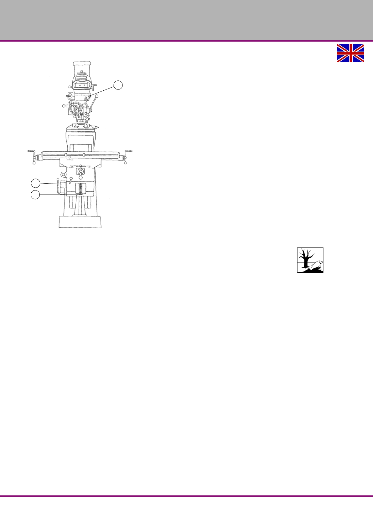
OPTIMUM
6
3
1
MASCHINEN - GERMANY
Img.5-3: Grease points
Always slightly oil bare surfaces.
INFORMATION!
Make sure that the coolant lubricants and oils are not split on the floor. Clean up any spilt liquid
or oils immediately using proper oil-absorption methods and dispose of them in accordance
with current legal requirements on the environment.
5.4 Maintenance
The type and level of wear depends to a large extent on the individual usage and operating
conditions. For this reason, all the intervals are only valid for the authorised conditions.
Perform a safety check.
Check for wear in the V-belts in the spindle head.
at the beginning of the
shift
every month Check that all clamping screws are firmly in place, every six months.
as required Top up cooling lubricant. Wash the cooling lubricant pump.
MF2 VarioGB
Version 1.3.0 dated 2016-12-16Page 46 Original operating instructions
Page 49

OPTIMUM
MASCHINEN - GERMANY
5.5 Repair
5.5.1 Customer service technician
For any repair work request the assist ance of an authorised customer service technician. Contact your specialist dealer if you do not have customer service's information or contact Stürmer
Maschinen GmbH in Germany who can provide you with a specialist dealer's contact information. Optionally, the
Stürmer Maschinen GmbH
Dr.-Robert-Pfleger-Str. 26
D- 96103 Hallstadt
can provide a customer service technician, however, the request for a customer service techni-
cian can only be made via your specialist dealer.
If the repairs are carried out by qualified technical personnel, they must follow the indications
given in these operating instructions.
Optimum Maschinen Germany GmbH accepts no liability nor does it guarantee against damage
and operating malfunctions resulting from failure to observe these operating instructions.
For repairs only use
faultless and suitable tools,
original parts or parts from series expressly authorised by Optimum Maschinen Germany
GmbH.
Version 1.3.0 dated 2016-12-16 Page 47Original operating instructions
MF2 Vario GB
Page 50
OPTIMUM
MASCHINEN - GERMANY
5.6 Cooling lubricants and tanks
CAUTION!
The cooling lubricant can cause diseases. Avoid direct contact with cooling lubricant or
parts covered in cooling lubricant.
Cooling lubricant circuits and tanks for water-cooling lubricant mixtures must be completely
emptied, cleaned and disinfected as needed, but at least once per year or every time the cooling lubricant is replaced.
If fine chips and other foreign matters are accumulated in the coolant tank, the machine can no
longer be correctly supplied with coolant. Furthermore, the lifetime of the coolant pump is
reduced.
When processing cast iron or similar materials generating fine chips, cleaning the coolant tank
more often is recommended.
Limit values
The cooling lubricant must be replaced, the cooling lubricant circuit and tank emptied,
cleaned and disinfected if
the pH value drops by more than 1 based on the value during initial filling. The maximum
permissible pH value during initial filing is 9.3
there is a p erceivable change in the appearance, odour, floating oil or increase of the bacte-
ria to more than 10/6/ml
there is an incr ease in nitrite content to more than 20 ppm (mg/1) or nitrate content to more
than 50 ppm (mg/1)
there is an increase in the N-nitrosodiethanolamine (NDELA) to more than 5 ppm (mg/a)
CAUTION!
Comply with the manufacturer's specifications for mixture rat ios, hazardous substances,
e.g. system cleaners, including their permissible minimum use times.
CAUTION!
Since the cooling lubricant escapes under high pressure, pumping out the coolant by
using the existing cooling lubricant pump via a pressure hose into a suitable tank is not
recommended.
ENVIRONMENTAL PROTECTION
During work on the cooling lubricant equipment please make sure that
collector tanks are used with sufficient capacity for the amount of liquid to be col-
lected.
liquids and oils should not be spilled on the ground.
Clean up any spilled liquid or oils immediately using proper oil-absorption methods and dispose of them in accordance with current statutory environmental regulations.
Collect leakages
Do not re-introduce liquids spilled outside the system during repair or as a result of leakage
from the reserve tank, instead collect them in a collecting container for disposal.
Disposal
Never dump oil or other substances which are harmful to the environment into water inlets, rivers or channels. Used oils must be delivered to a collection centre. Consult your supervisor if
you do not know where the collection centre is.
Coolant lubricatingEN
Version 1.3.0 dated 2016-12-16Page 48 Original operating instructions
coolant_GB.fm
Page 51

5.6.1 Inspection plan for water-mixed cooling lubricants
Company:
No.:
Date:
used cooling lubricant
OPTIMUM
MASCHINEN - GERMANY
size to be checked Inspection methods Inspection
intervals
noticeable
changes
pH value Laboratory techniques
Usage concentration Manual refractometer
Base reserve Acid titration in accordance
Nitrite content Test sticks method or labora-
Nitrate/nitrite content
of the preparation water, if
this is not removed from
the public
grid
Appearance, odour daily Find and rectify causes,
1)
1)
1)
electrometric with pH meter
(DIN 51369)
Local measurement method:
with pH paper
(Special indicators with
suitable measuring range)
with
Manufacturer's recommendation
tory method
Test sticks method or laboratory method
weekly
weekly
as required Method is independent of tramp oil content
weekly
as required Use water from the public grid if there is
Procedure and comment
e.g. skim off oil, check filter, ventilate cooling
lubricant system
if pH value decreases
> 0.5 based on initial filing:
Measures in accordance manufacturer's recommendations
> 1.0 based on initial filing:
Replace cooling lubricant, clean cooling lubricant circulation system
Method results in incorrect values with tramp
oil content
> 20 mg/L nitrite:
Replace cooling lubricant or part
or inhibiting additives;
otherwise NDELA (N-nitrosodiethanolamine)
in the cooling lubricant system and in the air
must be determined
> 5 mg/L NDELA in the cooling lubricant system:
Replacement,
clean and disinfect cooling lubricant circulation system, find nitrite source and, if possible, rectify.
water from the pubic grid has
> 50 mg/l nitrate: Inform the waterworks
1)
The specified inspection intervals (frequency) are based on continuous operation. Other operational
conditions can result in other inspection intervals; exceptions are possible in accordance with Sections 4.4
and 4.10 of the TGS 611.
Editor:
Signature:
coolant_GB.fm
Version 1.3.0 dated 2016-12-16 Page 49Original operating instructions
Coolant lubricating EN
Page 52
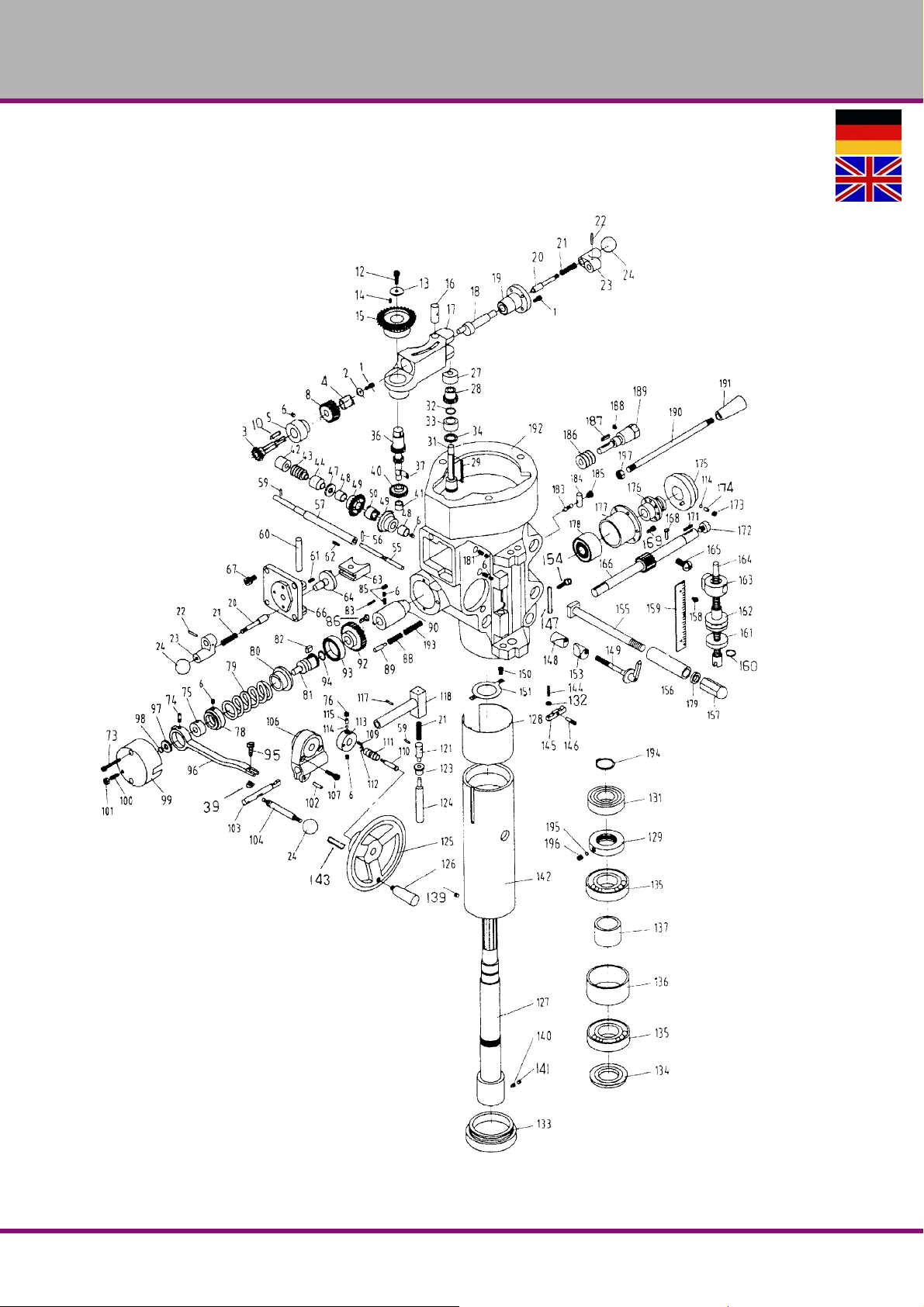
OPTIMUM
MASCHINEN - GERMANY
6 Ersatzteile - Spare parts - MF2 Vario
6.1 Spindelkopf Multifräsmaschine - Multi-milling machine spindle head
MF2 VarioDE | GB
Version 1.3.0 2016-12-16 50 Originalbetriebsanleitung
Page 53
OPTIMUM
MASCHINEN - GERMANY
Ersatzteilliste Spindelkopf - Spare part list spindle head
Bezeichnung Designation
Pos.
1 Sechskantschraube Hexagon-head screw 1 M6x12 TS-1503031 0333602011
2 Scheibe Washer 1 B-2 0333602012
3 Vorschubkegelrad Feed bevel wheel 1 B-3 0333602013
4 Buchse Schneckenwelle Worm shaft bushing 1 B-4 0333602014
5 Buchse Bushing 1 B-5 0333602015
6 Stellschraube Adjusting screw 1 M6x6 TS-1522011 0333602016
8 Schneckenrad Spiral wheel 1 B-8 0333602018
10 Keil Wedge 1 3x3x12 KEY3312 03336020110
12 Sechskantschraube Hexagon-head screw 1 M8x16 TS-1504031 03336020112
13 Scheibe Washer 1 B-13 03336020113
14 Keil Wedge 2 3x3x8 KEY3308 03336020114
15 Kegelrad Bevel wheel 1 B-15 03336020115
16 Vorschubschaltstift Feed actuating bolt 1 B-16 03336020116
17 Schneckenradhalter Spiral wheel support 1 B-17 03336020117
18 Welle Schneckenradhalter Shaft for spiral wheel support 1 B-18 03336020118
19 Wellenbuchse Shaft bushing 1 B-19 03336020119
20 Stößel Getriebewelle Drive shaft push rod 2 B-20 03336020120
21 Feder Spring 2 B-21 03336020121
22 Spannstift Dowel pin 2 3x20 B-22 03336020122
23 Schaltkurbel Switching handle 2 B23 03336020123
24 Kugel Ball 3 B-24 03336020124
25 Sechskantschraube Hexagon-head screw 3 M5x12 TS-1503010 03336020125
27 Buchse Bushing 1 B-27 03336020127
28 Getrieberad Gear wheel 1 B-28 03336020128
29 Keil Wedge 1 3x3x45 KEY3354 03336020129
31 Getriebewelle Gear shaft 1 B-31 03336020131
32 Sicherungsring Retaining ring 1 S-16 B-32 03336020132
33 Kegelradbuchse Bevel wheel bushing 1 B-33 03336020133
34 Distanzring Spacer ring 1 B-34 03336020134
36 Getrieberad Gear wheel 1 B-36 03336020136
39 Mutter Nut 1 M5 TS-1540031 03336020139
40 Vorschubrad Feed sprocket wheel 1 B-40 03336020140
41 Nadellager Needle bearing 1 B-41 03336020141
42 Buchse Bushing 1 B-42 03336020142
43 Schneckenrad Spiral wheel 1 B-43 03336020143
44 Buchse Bushing 1 B-44 03336020144
47 Scheibe Washer 1 B-47 03336020147
48 Buchse Bushing 2 B-48 03336020148
49 Kegelrad Bevel wheel 2 B-49 03336020149
50 Vorschub-Umkehr-Kupplung Feed reverse clutch 1 B-50 03336020150
54 Sechskantschraube Hexagon-head screw 1 M6x25 TS-1503061 03336020154
55 Zugstange Umkehrkupplung Reverse clutch drawbar 1 B-55 03336020155
56 Spannstift Dowel pin 1 3x20 B-56 03336020156
57 Vorschub-Schneckenwelle Feed worm shaft 1 B-57 03336020157
58 Stellschraube Adjusting screw 1 M6x6 TS-1523011 03336020158
59 Spannstift Dowel pin 2 3x12 B-59 03336020159
60 Späneschutz Filing guard 1 B-60 03336020160
61 Stellschraube Adjusting screw 1 M5x10 TS-1522031 03336020161
62 Keil Wedge 2 3x3x15 KEY3315 03336020162
63 Schaltgabel Engaging fork 1 B-63 03336020163
64 Schaltlager Coupling bearing 1 B-64 03336020164
66 Schaltdeckel Coupling cover 1 B-66 03336020166
67 Sechskantschraube Hexagon-head screw 4 M5x12 TS-1502031 03336020167
73 Sechskantschraube Hexagon-head screw 2 M5x35 TS-1502081 03336020173
74 Stift f. Kupplungsring Pin for coupling ring 2 B-74 03336020174
75 Kupplungsring Coupling ring 1 B-75 03336020175
76 Stellschraube Adjusting screw 1 M6x8 TS-1523021 03336020176
78 Kupplungsmutter Coupling nut 1 B-78 03336020178
79 Sicherheitskupplungsmutter Coupling locknut 1 B-79 03336020179
80 Überlastkupplung Overload coupling 1 B-80 03336020180
81 Hülse f. Überlastkupplung Bushing for overload coupling 1 B-81 03336020181
82 Keil Wedge 1 5x8x13 KEY5813 03336020182
83 Schraube Screw 3 B-83 03336020183
85 Stellschraube Adjusting screw 2 M6x6 TS-1523011 03336020185
86 Kreuzschlitzschraube Phillips screw 4 M4x16 B-86 03336020186
88 Feder Spring 1 B-88 03336020188
89 Federstößel Spring push rod 1 B-89 03336020189
90 Buchse Bushing 1 B-90 03336020190
Menge Größe Zeichnungsnr. Artikelnr.
Qty. Size Drawing no. Item no.
Version 1.3.0 2016-12-16 51Originalbetriebsanleitung
MF2 Vario DE | GB
Page 54
OPTIMUM
MASCHINEN - GERMANY
Ersatzteilliste Spindelkopf - Spare part list spindle head
Bezeichnung Designation
Pos.
92 Schneckenrad Spiral wheel 1 B-92 03336020192
93 Kupplungsring Coupling ring 1 B-93 03336020193
94 Sicherungsring Retaining ring 1 S-10 B-94 03336020194
95 Sechskantschraube Hexagon-head screw 1 M5x20 TS-1502051 03336020195
96 Kupplungshebel Coupling lever 1 B-96 03336020196
97 Kupplungsscheibe Clutch disk 1 B-97 03336020197
98 Sicherungsring Retaining ring 1 S-10 B-98 03336020198
99 Deckel Cover 1 B-99 03336020199
100 Stellschraube Adjusting screw 1 M6x16 C-19-1 033360201100
101 Mutter Nut 1 M6 TS-1540041 033360201101
102 Spannstift Dowel pin 1 5x18 B-102 033360201102
103 Nockenstange Cam rod 1 B-103 033360201103
104 Hebel Lever 1 B-104 033360201104
106 Halter f. Hebel Support for lever 1 B-106 033360201106
107 Sechskantschraube Hexagon-head screw 1 M6x20 TS-1503051 033360201107
108 Stellschraube Adjusting screw 1 M6x10 TS-1523031 033360201108
109 Keil Wedge 1 3x3x10 KEY3310 033360201109
110 Stift Pin 1 B-110 033360201110
111 Umkehrknopf Reverse button 1 B-111 033360201111
112 E-Ring E-Ring 1 E-6 B-112 033360201112
113 Kupplungsbetätigung Coupling actuator 1 B-113 033360201113
114 Stahlkugel Steel ball 2 3/16“ B-114 033360201114
115 Druckfeder Compression spring 2 B-115 033360201115
116 Stellschraube Adjusting screw 1 M8x6 B-116 033360201116
117 Spannstift Dowel pin 1 3x15 B-117 033360201117
118 Hülse Nockenstange Bushing for cam rod 1 B-118 033360201118
119 Federstift Spring bolt 1 3x12 B-119 033360201119
120 Druckfeder Compression spring 1 B-120 033360201120
121 Ausklinkkolben Release piston 1 B-121 033360201121
123 Buchse Bushing 4 B-123 033360201123
124 Vorschub Ausklinkkolben Release piston for fee d 1 B-124 033360201124
125 Handrad Hand wheel 1 B-125 033360201125
126 Griff Handle 1 B-126 033360201126
127 Spindel Spindle 1 B-127 033360201127
128 Pinolenummantelung Spindle sleeve jacket 1 B-128 033360201128
129 Wellenmutter Shaft nut 1 B-129 033360201129
131 Kugellager Ball bearing 1 6206ZZ BB-6206ZZ 040 6206.2R
132 Mutter Nut 1 M4 B-132 033360201132
133 Spindelspitze Spindle tip 1 B-133 033360201133
134 Spindel Abdeckung Spindle cover 1 B-134 033360201134
135 Lager Bearing 1 7207 BB-7207C 0407207
136 Distanzring Spacer ring 1 B-136 033360201136
137 Distanzring Spacer ring 1 B-137 033360201137
138 Lager Bearing 1 7207 BB-7207C 0407207
139 Stellschraube Adjusting screw 1 B-139 033360201139
140 Stellschraube Adjusting screw 1 B-140 033360201140
141 Stellschraube Adjusting screw 1 M6x6 TS-1523011 033360201141
142 Spindel Spindle 1 B-142 033360201142
143 Federstift Spring bolt 1 3x16 B-143 033360201143
144 Stellschraube Adjusting screw 1 M4x20 B-144 033360201144
145 Vorschub Ausklinkhebel Release lever for feed 1 B-145 033360201 145
146 Stift Ausklinkhebel Pin for release lever 1 B-146 033360201146
147 Kontrollstange Control rod 1 B-147 033360201147
148 Hülse Spindelklemmung Bushing for locking spindle 1 B-148 033360201148
149 Klemmgriff Tightening handle 1 B-149 033360201149
150 Schraube Screw 2 M5x8 B-150 033360201150
151 Scheibe Washer 2 M5 B-151 033360201151
153 Hülse Spindelklemmung Bushing for spindle locking 1 B-153 033360201153
154 Schraube f. Kontrollstange Screw for control rod 1 B-154 033360201154
155 Vierkantschraube Square-head bolt 4 B-155 033360201155
156 Distanzring Spacer ring 4 B-156 033360201156
157 Hutmutter Cap nut 4 B-157 033360201157
158 Schraube Screw 2 B-158 033360201158
159 Skala Scale 1 B-159 033360202109
160 Sicherungsring Retaining ring 1 S-16 B-160 033360201160
161 Einstellmutter Set nut 1 B-161 033360201161
162 Einstellmutter Set nut 1 B-162 033360201162
163 Anschlag Stop 1 B-163 033360201163
164 Einstellmutter Set nut 1 B-164 033360201164
Menge Größe Zeichnungsnr. Artikelnr.
Qty. Size Drawing no. Item no.
MF2 VarioDE | GB
Version 1.3.0 2016-12-16 52 Originalbetriebsanleitung
Page 55
OPTIMUM
MASCHINEN - GERMANY
Ersatzteilliste Spindelkopf - Spare part list spindle head
Bezeichnung Designation
Pos.
165 Schraube Screw 1 M10x15 B-165 033360201165
166 Vorschubwelle Feed shaft 1 B-166 033360201166
168 Stift Pin 1 B-168 033360201168
169 Sechskantschraube Hexagon-head screw 2 M5x12 TS-1503010 033360201169
171 Keil Wedge 1 3x3x20 KEY3320 033360201171
172 Schraube f. Pinolenhubwelle
173 Stellschraube Adjusting screw 1 5/16“x1/4“ B-173 033360201 173
174 Druckfeder Compression spring 1 B-174 033360201174
175 Hubring Return ring 1 B-175 033360201175
176 Muffe Sleeve 1 B-176 033360201176
177 Federgehäuse Spring box 1 B-177 033360201177
178 Spiralfeder Flat coil spring 1 B-178 033360201178
179 Scheibe Washer 4 B-179 033360201179
181 Stellschraube Adjusting screw 2 M6x12 TS-1523041 033360201181
183 Kugelhebel Ball lever 1 B-183 033360201183
184 Ausklinkkolben Release piston 1 B-183 033360201184
185 Schraube f. Kugelhebel Screw for ball lever 1 B-185 033360201185
186 Schneckenrad Spiral wheel 1 B-186 033360201186
187 Keil Wedge 1 4x4x18 KEY4418 033360201187
188 Stellschraube Adjusting screw 1 B-188 033360201188
189 Schneckenwelle Worm shaft 1 B-189 033360201189
190 Hebel f. Pinolenvorschub Lever for spindle sleeve feed 1 B-190 033360201190
191 Kugel Ball 1 B-191 033360201191
192 Spindelgehäuse Spindle box 1 B-192 033360201192
193 Druckfeder Compression spring 1 B193 033360201193
194 Sicherungsring Retaining ring 1 S-30 B-194 033360201194
195 Buchse Bushing 1 B-195 033360201195
196 Stellschraube Adjusting screw 1 M6x6 TS-1523011 033360201196
197 Mutter Nut 1 B-197 033360201197
Screw f. spindle sleeve return
shaft
Menge Größe Zeichnungsnr. Artikelnr.
Qty. Size Drawing no. Item no.
1 B-172 033360201172
Version 1.3.0 2016-12-16 53Originalbetriebsanleitung
MF2 Vario DE | GB
Page 56
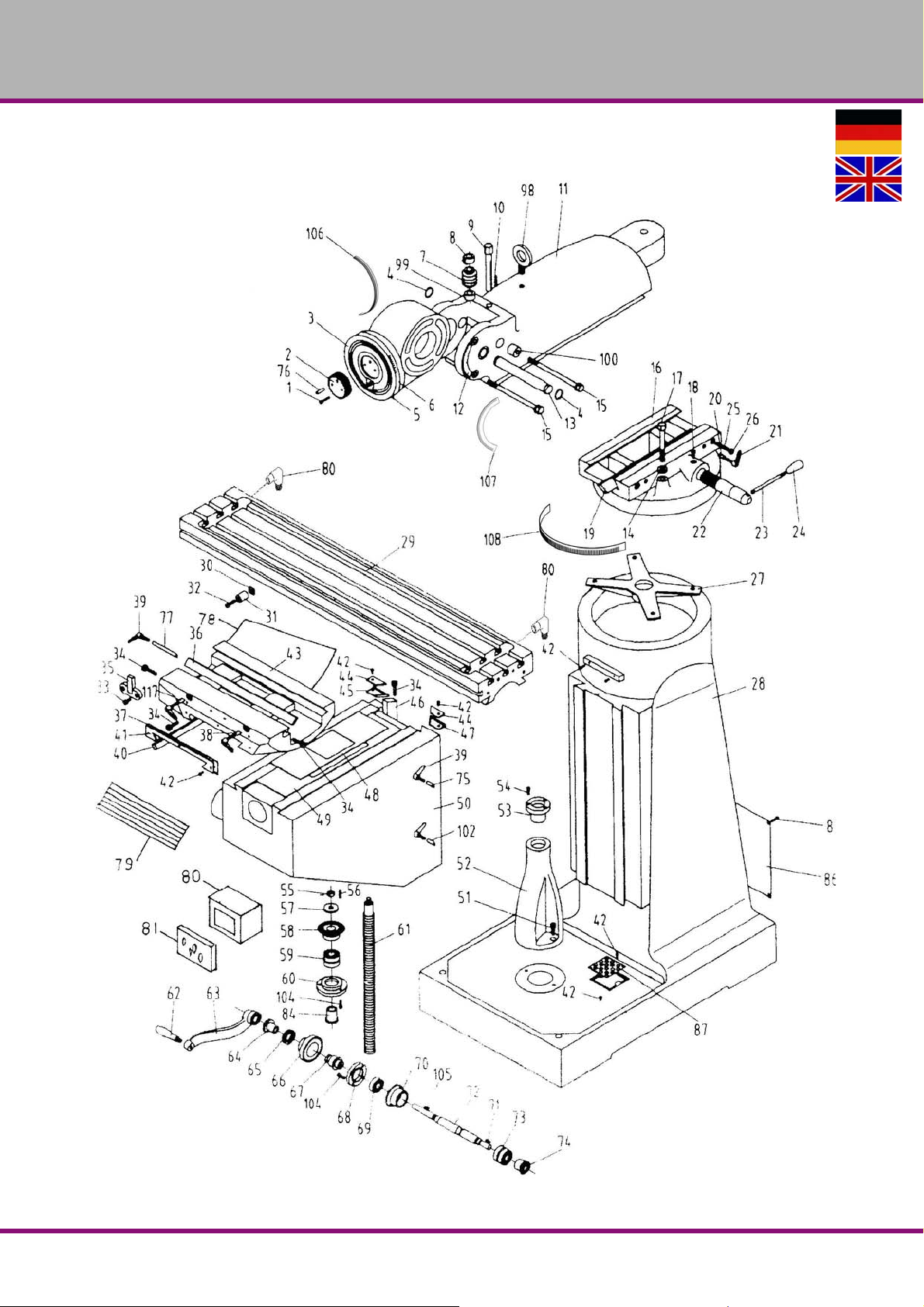
OPTIMUM
MASCHINEN - GERMANY
6.2 Grundkörper Multifräsmaschine - Body of the multi-milling machine
MF2 VarioDE | GB
Version 1.3.0 2016-12-16 54 Originalbetriebsanleitung
Page 57
OPTIMUM
MASCHINEN - GERMANY
Ersatzteilliste Grundkörper - Spare part list body of the milling machine
Bezeichnung Designation
Pos.
1 Sechskantschraube Hexagon-head screw 2 M6x30 LB-001 0333602021
2 Getrieberad Gear wheel 1 LB-023 0333602022
3 Schlitten-Adapter Carriage adapter 1 LB-020 0333602023
4 Sicherungsring Retaining ring 2 S-28 LB-004 0333602024
5 Niet Rivet 5 LB-005 0333602025
6 Adapter-Skala Adapter scale 1 LB-027 0333602026
7 Schnecke Worm screw 1 LB-035 0333602027
8 Druckscheibe Thrust washer 1 LB-036 0333602028
9 Stellschraube Adjusting screw 1 LB-034 0333602029
10 Keil Wedge 11 5x5x40 LB-100 03336020210
11 Schlitten Carriage 1 MB-026 03336020211
12 Winkelplatte Angular plate 1 LB-032 03336020212
13 Drehachse Rotating axle 1 LB-028 03336020213
14 Scheibe Washer 4 LB-031 03336020214
15 Feststellschraube Schlitten Tightening screw for carriage 3 LB-030 03336020215
16 Drehkopf Rotating head 1 MB-009 03336020216
0 Drehkopf-Skala (ohne Abb.) Scale of rotating head (not in fig.) 1 MB-00B 0333602020
17 Feststellschraube Tightening screw 4 LB-030 03336020217
18 Ritzelschraube f. Schlitten Pinion screw for carriage 1 LB-041 03336020218
Klemmleiste Schlitten/
19
20 Feststellstößel Locking push rod 2 LS-005E 03336020220
21 Klemmgriff Tightening handle 2 LB-014 03336020221
22 Schlittenritzel Carriage pinion 1 LB-015 03336020222
23 Griff Handle 1 LB-016 03336020223
24 Kugel Ball 1 LB-017 03336020224
25 Stellschraube Adjusting screw 2 3/8x2 TS-02113 1 03336020225
26 Sechskantmutter Hexagonal nut 2 3/8 TS-0561031 03336020226
27 Drehkreuz Turnstile 1 MB-008 03336020227
28 Ständer Upright 1 MB-000 03336020228
29 Kreuztisch Cross table 1 C-023 03336020229
30 Stopp Mutter Stop nut 2 LT-027 03336020230
31 Tischanschlag Table stop 2 LT - 028 03336020231
32 Sechskantschraube Hexagon-head screw 2 M8x35 TS-1504071 03336020232
33 Sechskantschraube Hexagon-head screw 2 M8x16 TS1504031 03336020233
34
35 Anschlag Stop 1 LS-003 03336020235
36 Klemmleiste Tisch/Träger Tightening rail for table/support 1 LS-008 03336020236
37 Filzabstreifer Felt scraper 2 LS-013 03336020237
38 Feststellstößel f. Tisch Locking push rod for table 2 LS-005 03336020238
39 Klemmhebel Tightening lever 5 LS-011 03336020239
40 Klemmleiste Träger/Tisch Tightening rail for support/table 1 LS-011 03336020240
41 Abstreiferplatte Scraper plate 2 LS-014 03336020241
42 Schraube Screw 16 LS-042 03336020242
43 Träger Support 1 MS-000 03336020243
44 Filzabstreifer Felt scraper 2 LS-017A 03336020244
45 Filz (links) Felt (left) 1 LS-016A 03336020245
46 Klemmleiste Konsole/St änder Tightening rail for console/upright 1 LK-001 03336020246
47 Filz Konsolenabstreifer (rechts) Felt for console scraper (right) 1 LS-016 03336020247
48 Oberer Späneschutz Upper filing guard 1 LK-007 03336020248
49 Unterer Späneschutz Lower filing guard 1 LK-006 03336020249
50 Konsole Console 1 MK-000 03336020250
51 Sechskantschraube Hexagon-head screw 2 M10x25 TS-1505031 03336020251
52 Hubspindelgehäuse Casing of lifting spindle 1 MK-012 03336020252
53 Hubspindelmutter Lifting spindle nut 1 MK-014 03336020253
54 Sechskantschraube Hexagon-head screw 8 M6x16 TS-1503041 03336020254
55 Sechskantmutter Hexagonal nut 1 1/2-20UNF TS-0561052 03336020255
56 Keil Wedge 1 4x4x30 LK-058 03336020256
57 Scheibe Washer 1 LK-022 03336020257
58 Kegelrad Bevel wheel 1 MK-021 03336020258
59 Kugellager Ball bearing 2 BB-6306ZZ 0406306
60 Lagerdeckel Bearing cover 1 MK-019 03336020260
61 Hubspindel Lifting spindle 1 MK-016 03336020261
62 Griff Handle 1 LK-037 03336020262
63 Kurbel Crank handel 1 LK-036 03336020263
64 Kupplungseinsatz Coupling insert 1 LK-035 03336020264
65 Skalenhaltemutter Nut for scale support 1 LK-034 03336020265
Drehkopf
Einstellschraube f.
Klemmleiste
Tightening rail for carriage/ro tating
Adjusting screw for tightening rail 6 LK-002 03336020234
head
Menge Größe Zeichnungsnr. Artikelnr.
Qty. Size Drawing no. Item no.
1 LB-011 03336020219
Version 1.3.0 2016-12-16 55Originalbetriebsanleitung
MF2 Vario DE | GB
Page 58

OPTIMUM
MASCHINEN - GERMANY
Ersatzteilliste Grundkörper - Spare part list body of the milling machine
Bezeichnung Designation
Pos.
66 Skala Scale 1 LK-033 03336020266
67 Skalenhalter Scale support 1 LK-032 03336020267
68 Lagerdeckel Bearing cover 1 LK-030 03336020268
69 Kugellager Ball bearing 1 BB-6204ZZ 0406204.2R
70 Lagerdeckel Bearing cover 1 LK-029 03336020270
71 Keil Wedge 2 4x4x18 LK-075 03336020271
72 Hubwelle Lifting shaft 1 MK-028 03336020272
73 Kugellager Ball bearing 2 BB-6204ZZ 0406204.2R
74 Kegelritzel Conical pinion 1 MK-024 03336020274
75 Stößel Push rod 1 LK-003 03336020275
76 Spannhülse Securing sleeve 1 8x30 LK-081 03336020276
77 Feststellstößel für Träger Locking push rod for support 1 LS-010 03336020277
78 Späneschutz Filing guard 1 C-34 03336020278
79 Staubschutzabdeckung Dust cover 1 C-63 03336020279
80 Schlauchtülle Hose connector 2 1/2“ 03336020280
83 Schraube Screw 4 1/4x3/8 MB-090 03336020283
84 Büchse Sleeve 1 MK-038 03336020284
86 Abdeckung Cover 1 MB-004 03336020286
87 Sieb Screen 1 MB-041 03336020287
98 Augenschraube Eye bolt 1 RIBW34 03336020298
99 Druckscheibe f. Schnecke Thrust washer for worm screw 1 LB-036 03336020299
100 Druckscheibe Thrust washer 1 LB-033 033360202100
102 Feststellstößel Locking push rod 1 LK-003 033360202102
104 Sechskantschraube Hexagon-head screw 6 M6x20 TS-1503051 033360202104
105 Keil Wedge 1 3x3x20 KEY3320 033360202105
106 Skala Scale 1 033360202106
107 Skala Scale 1 033360202107
108 Skala Scale 1 033360202108
Menge Größe Zeichnungsnr. Artikelnr.
Qty. Size Drawing no. Item no.
MF2 VarioDE | GB
Version 1.3.0 2016-12-16 56 Originalbetriebsanleitung
Page 59
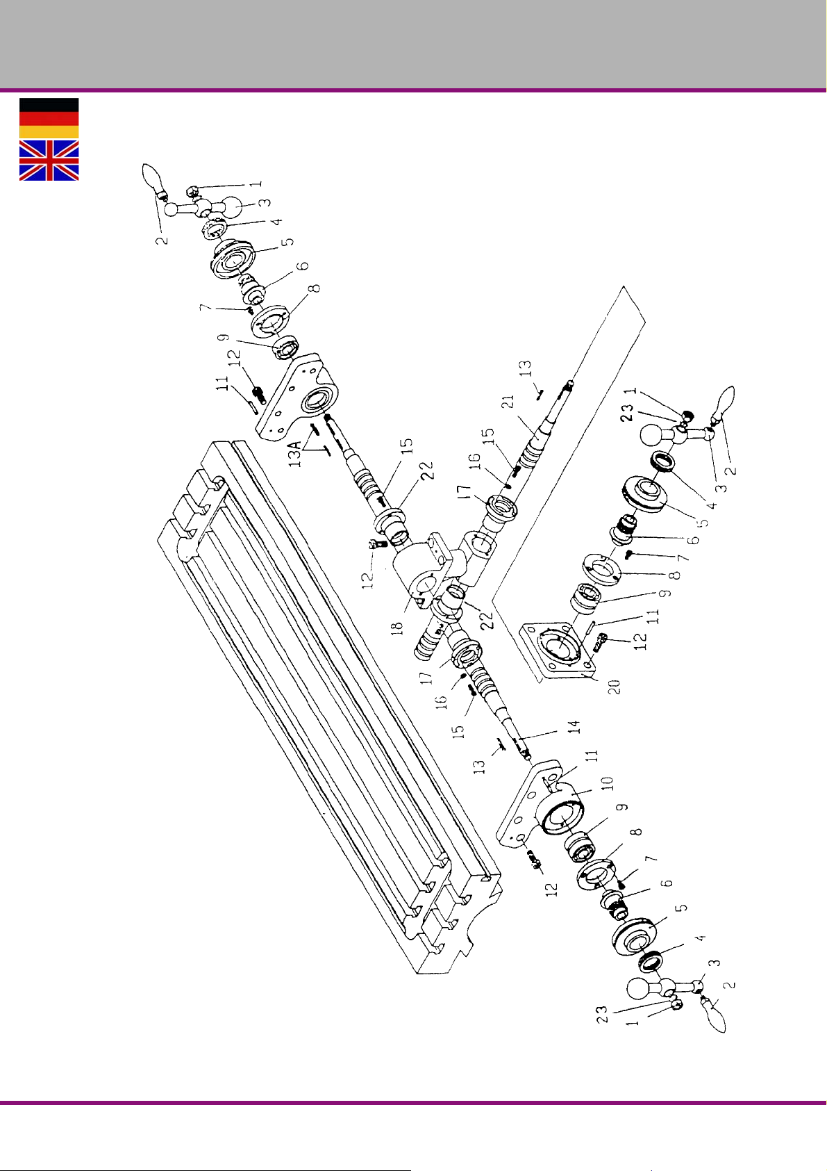
6.3 Spindeln Frästisch - Spindles milling table
OPTIMUM
MASCHINEN - GERMANY
Version 1.3.0 2016-12-16 57Originalbetriebsanleitung
MF2 Vario DE | GB
Page 60
OPTIMUM
MASCHINEN - GERMANY
Ersatzteilliste Spindeln Frästisch - Spare parts list spindles milling table
Bezeichnung Designation
Pos.
1 Mutter Nut 3 1/2“-20NF D-1 0333602031
2 Griff Handle 3 D-2 0333602032
3 Kugekkurbel Handle with ball counterbalance 3 D-3 0333602033
4 Skalenmutter Scale nut 3 D-4 0333602034
5 Skala Scale 3 D-5 0333602035
6 Skalenhalter Scale support 3 D-6 0333602036
7 Sechskantschraube Hexagon-head screw 9 M6x12 TS-1503031 0333602037
8 Lagerdeckel Bearing cover 3 C-90 0333602038
9 Kugellager Ball bearing 5 BB-6204ZZ 0406204.2R
10 Lagergehäuse Bearing box 2 D-10 03336020310
11 Spannstift Dowel pin 6 5x25 D11 03336020311
12 Sechskantschraube Hexagon-head screw 16 TS-1505031 03336020312
13 Keil Wedge 2 3x3x25 KEY3325 03336020313
13a Keil Wedge 2 3x3x18 KEY3325 03336020313a
14 Leitspindel L ead spindle 1 D-14 03336020314
15 Sechskantschraube Hexagon-head screw 10 TS-1503061 03336020315
16 Scheibe Washer 4 H-9 03336020316
17 Spindelmutter Spindle nut 2 D-17 03336020317
18 Spindelmuttergehäuse Casing of spindle nut 1 D-18 03336020318
20 Kreuzlagergehäuse Cross-bearing case 1 D-20 03336020320
21 Spindel Kreuzvorschub Cross-feed spindle 1 D-21 03336020321
22 Spindelmutter Kreuzvorschub Cross-feed spindle nut 1 D-22 03336020322
23 Federring Spring washer 3 D-23 03336020323
Menge Größe Zeichnungsnr. Artikelnr.
Qty. Size Drawing no. Item no.
MF2 VarioDE | GB
Version 1.3.0 2016-12-16 58 Originalbetriebsanleitung
Page 61
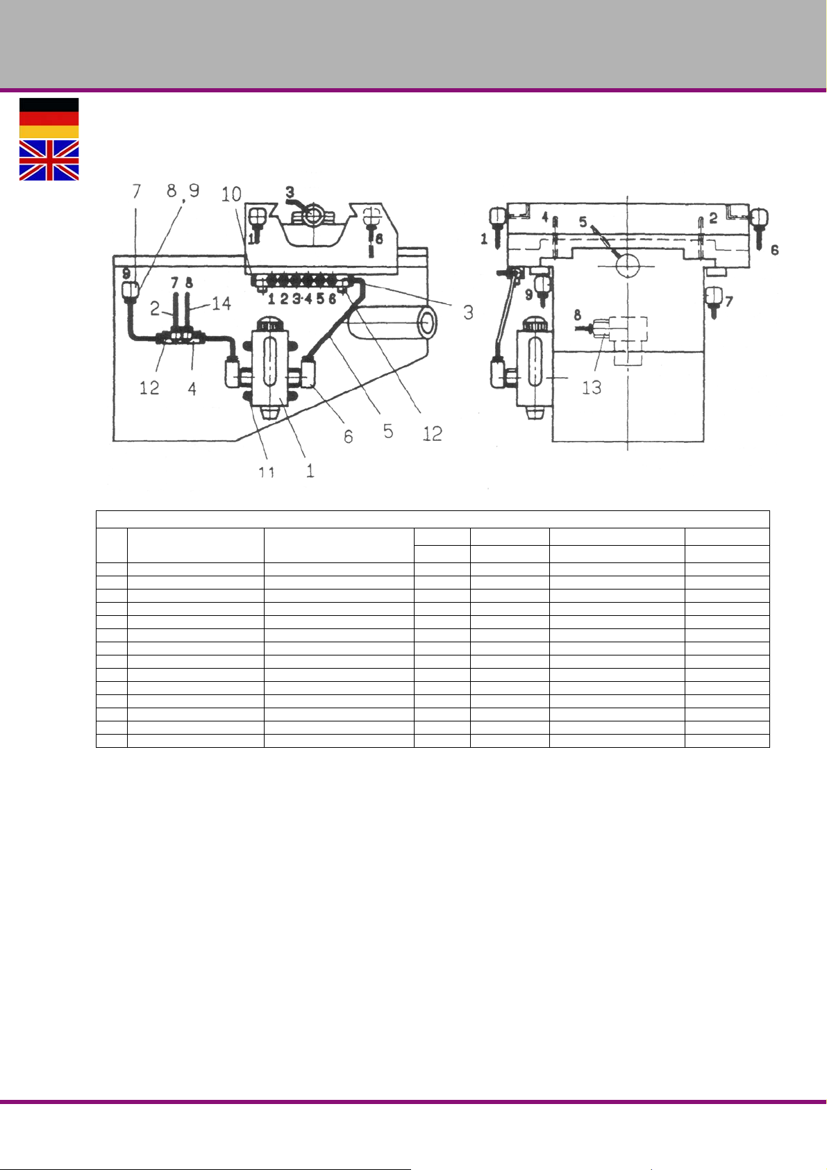
6.4 Zentralschmierung - Central lubrication
OPTIMUM
MASCHINEN - GERMANY
Ersatzteilliste Zentralschmierung - Spare parts list central lubrication
Bezeichnung Designation
Pos.
1 Öler Oil filler cup 1 CLA-8 0333602041
2 Aluminiumstück Aluminium piece 1 13,5 ALMP-04 0333602042
3 Öl-Regelverteiler Oil regulation distributor 1 A-8 0333602043
4 Öl-Regelverteiler Oil regulation distributor 1 A-4 0333602044
5 flexibler Stahlschlauch Flexible steel tube 1 4x550 A-5 0333602045
6 Winkelanschluss Angular connection 2 PH-4011 0333602046
7 Winkelanschluss Angular connection 6 PI-401 0333602047
8 Überwurfmutter Swivel nut 20 PA-4 0333602048
9 Hülse Bushing 20 PB-4 0333602049
10 Anschlussstück Connection piece 1 PG-004 03336020410
11 Schraube Screw 4 M6x14 03336020411
12 Sechskantschraube Hexagon-head screw 4 M5x25 TS-1502061 03336020412
13 Anschluss Joint 1 PD-401 03336020413
14 Nylonstück Nylon piece 1 4x700 A-14 03336020414
Menge Größe Zeichnungsnr. Artikelnr.
Qty. Size Drawing no. Item no.
Version 1.3.0 2016-12-16 59Originalbetriebsanleitung
MF2 Vario DE | GB
Page 62
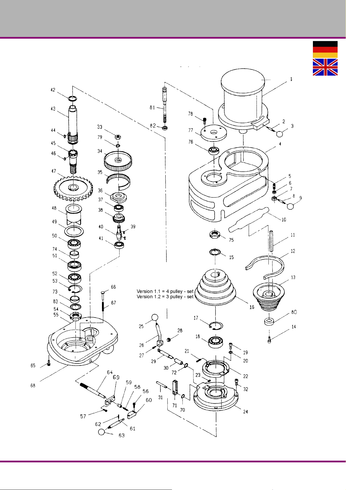
OPTIMUM
MASCHINEN - GERMANY
6.5 Spindelantrieb - Drive mechanism of the spindle
MF2 VarioDE | GB
Version 1.3.0 2016-12-16 60 Originalbetriebsanleitung
Page 63
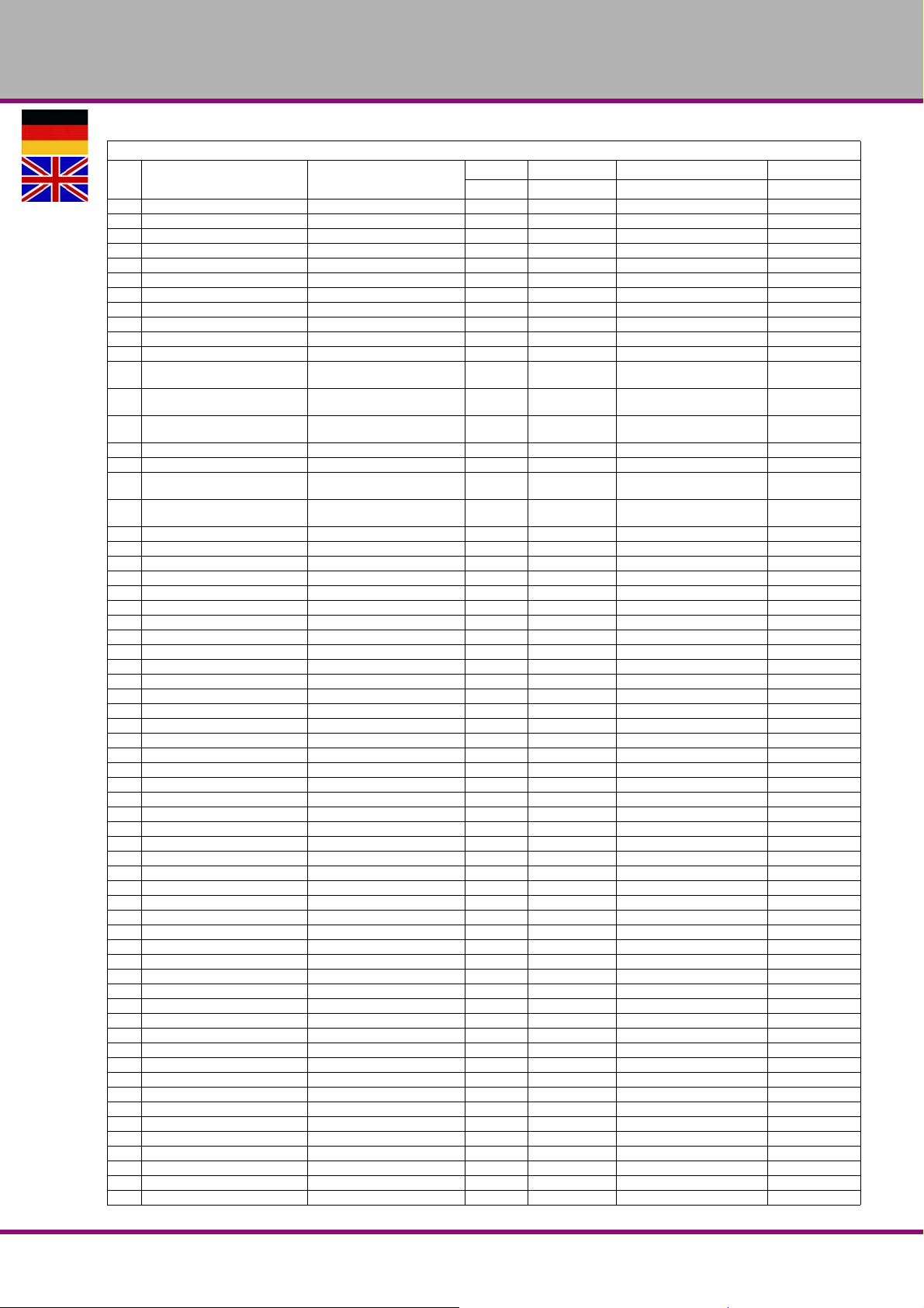
OPTIMUM
MASCHINEN - GERMANY
Ersatzteilliste Spindelantrieb - Spare parts list drive mechanism of the spindle
Pos.
Bezeichnung Designation
1 Motor Motor 1 2HP-4P 03336040M1
2 Gewindestift Set screw 1 A-40 0333602052
3 Kugel Ball 1 A-46 0333602053
4 Gehäuse Casing 1 0333602054
5 Schraube Screw 2 A-41 0333602055
6 Scheibe Washer 2 A-44 0333602056
7 Mutter Nut 2 A-43 0333602057
8 Griff Handle 2 A-45 0333602058
9 Kugel Ball 2 A-46 0333602059
10 Abdeckung Cover 2 03336020510
11 Keil Wedge 1 8x7x60L 03336020511
12 Riemen Belt 1
Riemenscheibe Maschinenver-
13
Riemenscheibe Maschinenver-
13-1
14 Sechskantschraube Hexagon-head screw 1 M8x25L 03336020514
15 Scheibe Washer 1 AW-10 03336020515
Riemenscheibe Maschinenver-
16
Riemenscheibe Maschinenver-
16-1
17 Sicherungsring Retaining ring 1 H-80 03336020517
18 Kugellager Ball bearing 1 6010ZZ 0406010.2R
19 Sechskantschraube Hexagon-head screw 1 M6x16L 03336020519
20 Scheibe Washer 1 VS-48 03336020520
21 Feder Spring 2 VS-49 03336020521
22 Bremse Brake 1 VS-47 03336020522
23 Stellschraube Adjusting screw 1 M6x16L 03336020523
24 Bremsgehäuse Brake casing 1 VS-50 03336020524
25 Kugel Ball 1 VS-57 03336020525
26 Hebel Lever 1 VS-56 03336020526
27 Sechskantschraube Hexagon-head screw 1 M6x25L 03336020527
28 Mutter Nut 1 M6 03336020528
29 Steuerwelle Reversing shaft 1 VS-53 03336020529
30 Buchse Bushing 1 VS-52 03336020530
31 Stift Pin 1 VS-58 03336020531
32 Sechskantschraube Hexagon-head screw 4 M8x25L 03336020532
33 Mutter Nut 1 5/8“ 03336020533
34 Zahnriemenscheibe Pulley for toothed belt 1 VS-62 03336020534
35 Zahnriemen Toothed belt 1 225L100 03336020535
36 Lagerdeckel Bearing cover 1 VS-64 03336020536
37 Kugellager Ball bearing 1 6203ZZ 6203.2R
38 Getrieberad Gear wheel 1 VS-66 03336020538
39 Keil Wedge 1 5x5x15L 03336020539
40 Welle Welle 1 VS-67 03336020540
41 Kugellager Ball bearing 1 6203ZZ 0406203.2R
42 Scheibe Washer 1 VS-98 03336020542
43 Welle Welle 1 A-20 03336020543
44 Keil Wedge 1 8x7x20L 03336020544
45 Kupplungswelle Clutch shaft 1 A-73 03336020545
46 Keil Wedge 1 8x7x12L 03336020546
47 Getrieberad Gear wheel 1 VS-74 03336020547
48 Flanschring Ring with flange 1 VS-75 03336020548
49 Scheibe Washer 1 VS-76 03336020549
50 Kugellager Ball bearing 1 6910ZZ 0406910
51 Distanzring Spacer ring 1 VS-79 03336020551
52 Kugellager Ball bearing 1 6910ZZ 0406910
53 Sicherungsring Retaining ring 1 H-72 03336020553
54 Wellenmutter Shaft nut 1 A-74 03336020554
55 Gehäuseunterteil Bottom of casing 1 03336020555
56 Sechskantschraube Hexagon-head screw 2 M5x16L 03336020556
57 Sechskantschraube Hexagon-head screw 2 M5x20L 03336020557
58 Feder Spring 1 03336020558
59 Stift Pin 1 VS-90 03336020559
60 Steuerteil Control piece 1 VS-92 03336020560
61 Griff Handle 1 VS-94 03336020561
62 Stift Pin 1 ø3x20 03336020562
sion 1.1
sion 1.2
sion 1.1
sion 1.2
Pulley machine version 1.1 1 4 pulley - set A-49 03336020513
Pulley machine version 1.2 1 3 pulley - set 033360205131
Pulley machine version 1.1 1 4 pulley - set A-19 03336020516
Pulley machine version 1.2 1 3 pulley - set 033360205161
Menge Größe Zeichnungsnr. Artikelnr.
Qty. Size Drawing no. Item no.
RECMF8330 -
17X815Li
03336020512
Version 1.3.0 2016-12-16 61Originalbetriebsanleitung
MF2 Vario DE | GB
Page 64
OPTIMUM
MASCHINEN - GERMANY
Ersatzteilliste Spindelantrieb - Spare parts list drive mechanism of the spindle
Pos.
Bezeichnung D esignation
63 Kugel Ball 1 B-105 03336020563
64 Welle Shaft 1 VS-87 03336020564
65 Sechskantschraube Hexagon-head screw 1 M8x20L 03336020565
66 Stift Pin 3 VS-102 03336020566
67 Feder Spring 3 VS-84 03336020567
68 Gehäuseunterteil Bottom of casing 1 03336020568
69 Steuerplatte Control plate 1 VS-89 03336020569
70 Sicherungsring Retaining ring 1 S-8 03336020570
71 Bremshebel Brake lever 1 VS-59 03336020571
72 Sicherungsring Retaining ring 1 S-12 03336020572
73 Distanzring Spacer ring 1 VS-105 03336020573
74 Distanzring Spacer ring 1 VS-78 03336020574
75 Wellenmutter Shaft nut 1 AW-50 03336020575
76 Kugellager Ball bearing 1 6009ZZ 0406009.2Z
77 Lagerdeckel Bearing cover 1 VS-13 03336020577
78 Sechskantschraube Hexagon-head screw 1 M6x16L 03336020578
79 Federring Spring washer 1 5/8“ VS-62 03336020579
80 Scheibe Washer 1 VS-7 03336020580
81 Zugstange Drawbar 1 VS-114 03336020581
82 Scheibe Washer 1 VS-115 03336020582
83 Sicherungsblech Safety plate 1 MB10 0340195
Menge Größe Zeichnungsnr. Artikelnr.
Qty. Size Drawing no. Item no.
MF2 VarioDE | GB
Version 1.3.0 2016-12-16 62 Originalbetriebsanleitung
Page 65
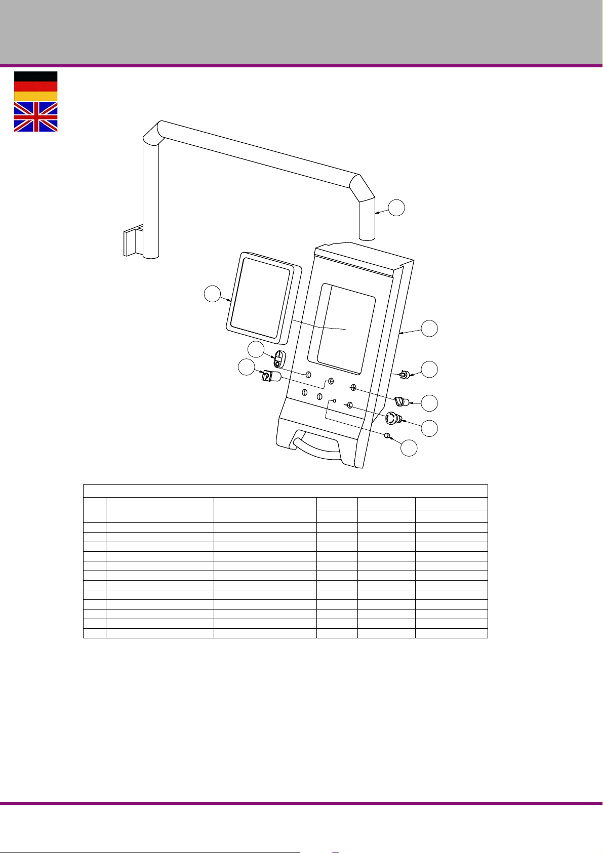
OPTIMUM
5
6
1
10
4
3
9
8
7
MASCHINEN - GERMANY
6.6 Bedienpanel ab Jahr 2016 - Control panel from year 2016
Ersatzteilliste Bedienpanel - Spare parts list control panel
Pos.
Bezeichnung Designation
1 B edienpanel Control panel 1 0333603001
3 Not-Aus-Schlagschalter Emergency-stop button 1 03336040SB1
4 Schalter Kühlmittelpumpe C oolant pump switch 1 03336040SA1
5 Träger Holder 1 0333603005
6 Digitalpositionsanzeige Digital position display 1 0333603006
7 Drehrichtungsschalter Change-over switsch 1 03336040S4
8 Ein-Aus-Taster ON-OFF switch 1 03336040SB2
9 Knopf Knob 1 03336030069
10 Potentiometer Potentiometer 1 03336040P3
Messleiste X-Achse Measuring gib X-axis 1 ML820 3384182
Messleiste Y-Achse Measuring gib Y-axis 1 ML320 3384132
Messleiste Y-Achse Measuring gib Z-axis 1 ML320 3384142
Menge Größe A rtikelnr.
Qty. Size Item no.
Version 1.3.0 2016-12-16 63Originalbetriebsanleitung
MF2 Vario DE | GB
Page 66
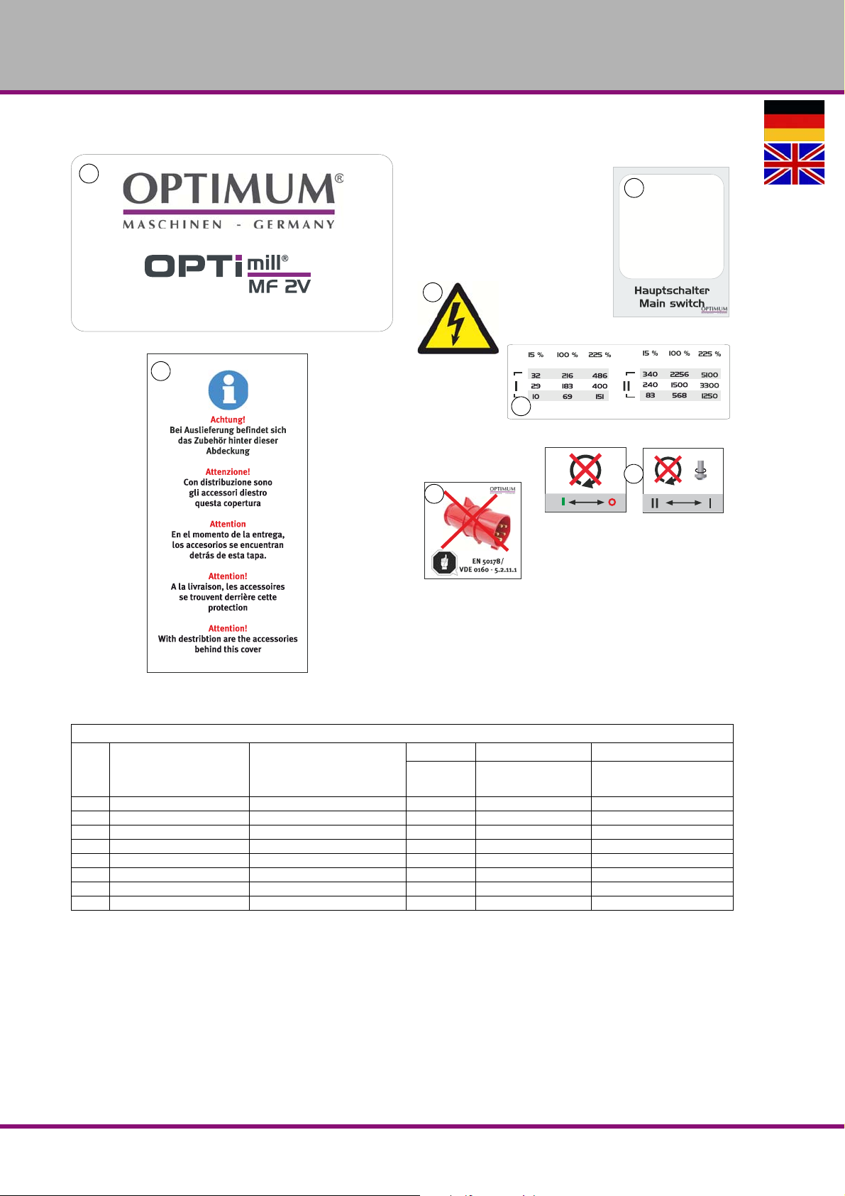
OPTIMUM
2
optimum-maschinen.de
Master Labels
3
72 x 93 mm
50 x 40 mm
60 x 60 mm
Master Labels
50 x 40 mm
8
6
5
9
11
MASCHINEN - GERMANY
6.7 Maschinenschilder - Machine labels
Abb.6-1: Maschinenschilder - Machine labels
Maschinenschilder - Machine labels
Pos.
1 Schild Steuerpanel Control board label 1 03336020L01
2 Infoschild Info label 1 03336020L02
3 Frontschild Front label 1 03336020L03
5 Hinweisschild Instruction label 1 03336020L05
6 Hinweisschild Instruction label 1 03336020L06
8 Sicherheitsschild Safety label 1 03336020L08
9 Hinweisschild Instruction label 1 03336020L09
11 Schild Hautpschalter Main switch label 1 03336020L11
Bezeichnung Designation
MF2 VarioDE | GB
Menge Grösse Artikelnummer
Quan-
tity
Size Article no.
Version 1.3.0 2016-12-16 64 Originalbetriebsanleitung
Page 67
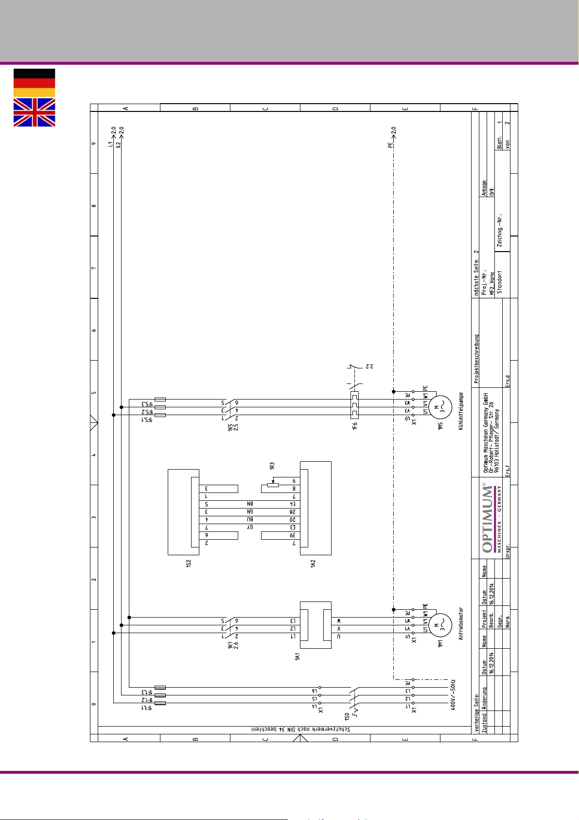
6.8 Schaltplan 1 von 2 - Wiring diagram 1 of 2
OPTIMUM
MASCHINEN - GERMANY
Version 1.3.0 2016-12-16 65Originalbetriebsanleitung
MF2 Vario DE | GB
Page 68
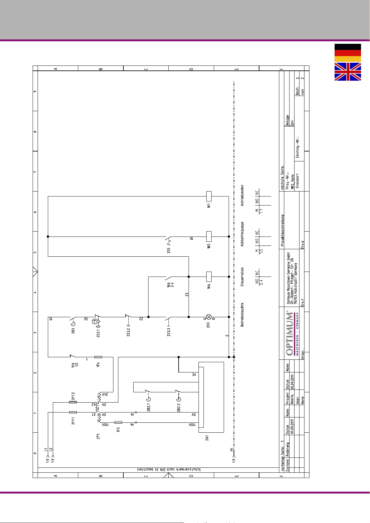
OPTIMUM
MASCHINEN - GERMANY
6.9 Schaltplan 2 von 2 - Wiring diagram 2 of 2
MF2 VarioDE | GB
Version 1.3.0 2016-12-16 66 Originalbetriebsanleitung
Page 69
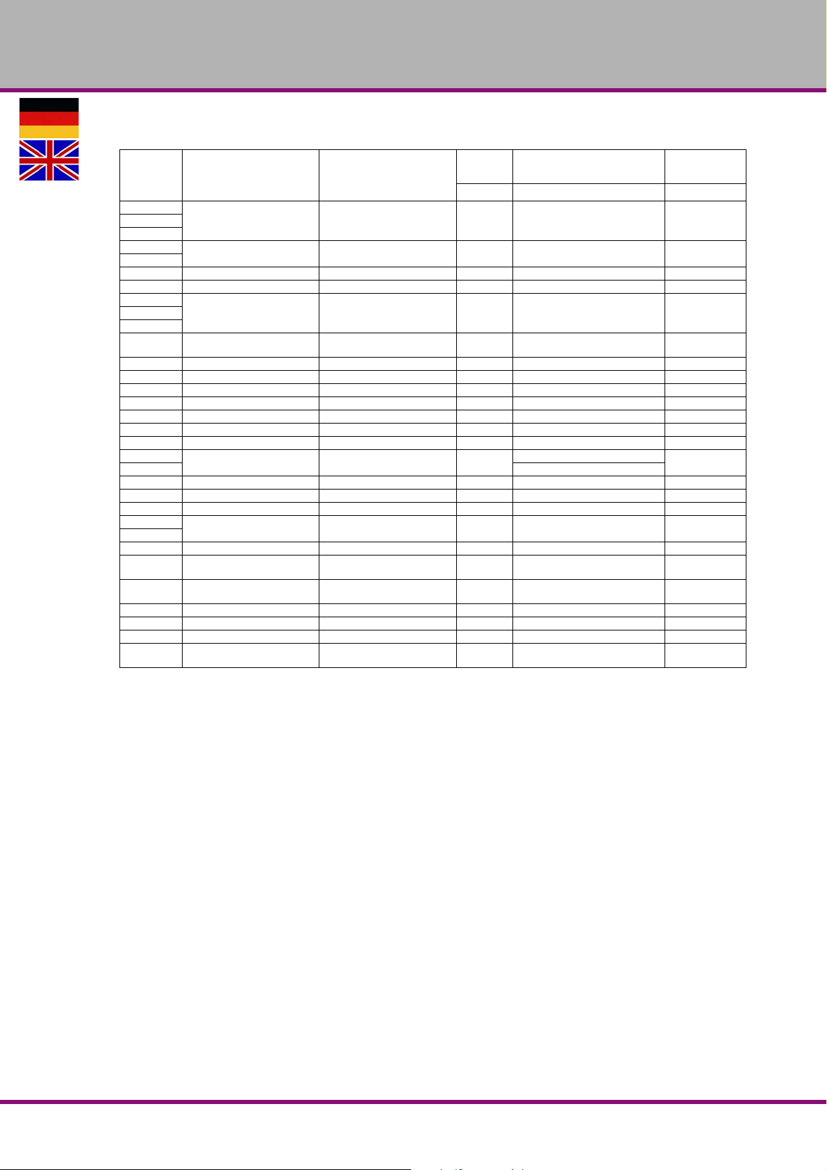
OPTIMUM
MASCHINEN - GERMANY
6.9.1 Ersatzteilliste elektrische Bauteile - Spare part list electrical components
Pos.
Bezeichnung Designation
1F1.1
1F1.3
2F1.1
2F1.2
1F3 Sicherung 10x38 (AM) Fuse 10x38 (AM) 1 4 A / AC 500V 03336040FU3
1F4 Sicherung 10x38 (AM) Fuse 10x38 (AM) 1 4 A / AC 500V 03336040FU4
1F5.1
1F5.3
1F6 Motorschutzschalter Motor safety switch 1 Telemecanique LR3D/03 03336040FR2
1K1 Motorschütz Motor contactor 1 Telemecanique LC1/DO9 03336040KM1
1K5 Motorschütz Motor contactor 1 Telemecanique LC1/DO9 03336040KM5
1K6 Motorschütz Motor contactor 1 Telemecanique LC1/DO9 03336040KM6
2T1 Transformer Transformator 1 LCP-TBSM/400V-400VA 03336040TC1
2S3.1 Not-Halt Schalter Emergency stop button 1 03336040SB1
2B3 Schalter Fräsfutterschutz Milling chuck safety switch 1 03336040SQ1
2S3.3
2S3.2
1S0 Hauptschalter Main switch 1 ABB/OT 16E3 03336040QS1
1S2 Drehrichtungsschalter Change-over switch 1 A400 F87105/001 DES 03336040S4
2S5 Schalter Kühlmittelpumpe Coolant pump switch 1 03336040SA1
2B2.1
2B2.2
2H3 Betriebskontrolleuchte Work light 1 03336040PL1
1M1 Spindelmotor Spindle motor 1
1M5 Motor Kühlmittelpumpe Motor coolant pump 1
1A1 Frequenzumrichter Frequency converter 1 Lenze/motec 8200 03336040C5
1A2 Funktionsmodul Functional module 1 033360401A2
1R3 Potentiometer Potentiometer 1 03336040P3
2A1 Tischvorschub X Achse Power Feed X-Axis 1
Sicherung 10x38 (AM) Fuse 10x38 (AM) 3 16 A / AC 500V 03336040FU11F1.2
Sicherung 10x38 (AM) Fuse 10x38 (AM) 2 2 A / AC 500V 03336040FU2
Sicherung 10x38 (AM) Fuse 10x38 (AM) 3 1 A / AC 500V 03336040FU51F5.2
Sicherungshalter Fuse holder 10
Ein-Aus-Taster On-off button 1 03336040SB2
Endschalter Tischvorschub End switch table feed 1 033360402B2
Menge Größe
Qty. Size Item no.
Telemecanique DF6 AB10;
IEC947-3
3.7 KW; 4P; 400V; 8A; 3 ~ 50Hz
0.1 KW; 2P 400V; 0.17A; 285 0
AC 110V 200W; 1 ~ 50Hz; 0-200
1400 rpm
rpm
rpm
Artikel-
nummer
03336040FUX
03336040M1
03336040M3
033360402A1
Version 1.3.0 2016-12-16 67Originalbetriebsanleitung
MF2 Vario DE | GB
Page 70
1.3.0 2016-12-16 68
Schmierstoffe
Lubricant
Lubrifiant
Viskosität
Viskosity
Viscosité ISO VG
DIN 51519 mm²/s
(cSt)
Kennzeich-
nung nach
DIN 51502
Getriebeöl
Gear oil
Huile de réducteur
Hydrauliköl
Hydraulic oil
Huile hydraulique
Getriebefett
Gear grease
Graisse de
réducteur
VG 680 CLP 680
VG 460 CLP 460
VG 320 CLP 320
VG 220 CLP 220
VG 150 CLP 150
VG 100 CLP 100
VG 68 CLP 68
VG 46 CLP 46
VG 32 CLP 32
VG 32 CLP 32
VG 46 CLP 46
G 00 H-20
Aral Degol BG
680
Aral Degol BG
460
Aral Degol BG
320
Aral Degol BG
220
Aral Degol BG
150
Aral Degol BG
100
Aral Degol BG
68
Aral Degol BG
46
Aral Degol BG
32
Aral Vitam GF 32BP Energol
Aral Vitam GF 46BP Energol
Aral FDP 00
(Na-verseift)
Aralub MFL 00
(Li-verseift)
BP Energol
GR-XP 680
BP Energol
GR-XP 460
BP Energol
GR-XP 320
BP Energol
GR-XP 220
BP Energol
GR-XP 150
BP Energol
GR-XP 100
BP Energol
GR-XP 68
BP Bartran
46
BP Bartran
32
HLP HM 32
HLP HM 46
BP
Energrease
PR-EP 00
SPARTAN
EP 680
SPARTAN
EP 460
SPARTAN
EP 320
SPARTAN
EP 220
SPARTAN
EP 150
SPARTAN
EP 100
SPARTAN
EP 68
NUTO H 46
(HLP 46)
NUTO H 32
(HLP 32)
NUTO H 32
(HLP 32)
NUTO H 46
(HLP 46)
FIBRAX EP
370
(Na-verseift)
Klüberoil
GEM 1-680
Klüberoil
GEM 1-460
Klüberoil
GEM 1-320
Klüberoil
GEM 1-220
Klüberoil
GEM 1-150
Klüberoil
GEM 1-100
Klüberoil
GEM 1-68
Klüberoil
GEM 1-46
Klübersynth
GEM 4- 32 N
LAMORA
HLP 32
LAMORA
HLP 46
MICRO-
LUBE GB 00
Mobilgear
636
Mobilgear
634
Mobilgear
632
Mobilgear
630
Mobilgear
629
Mobilgear
627
Mobilgear
626
Mobil DTE
25
Mobil DTE
24
Mobil Nuto
HLP 32
Mobil Nuto
HLP 46
Mobilux
EP 004
Shell Omala
680
Shell Omala
460
Shell Omala
320
Shell Omala
220
Shell Omala
150
Shell Omala
100
Shell Omala
68
Shell Tellus
S 46
Shell Tellus
S 32
Shell Tellus
S2 M 32
Shell Tellus
S2 M 46
Shell Alvania
GL 00
(Li-verseift)
Meropa 680
Meropa 460
Meropa 320
Meropa 220
Meropa 150
Meropa 100
Meropa 68
Anubia EP
46
Anubia EP
32
Rando HD
HLP 32
Rando HD
HLP 46
Marfak 00
MASCHINEN - GERMANY
OPTIMUM
Page 71

Spezialfette,
wasserabweisend
Special greases,
water resistant
Graisses spéciales,
déperlant
Aral Aralub
Energrease
PR 9143
ALTEMP
Q NB 50
Klüberpaste
ME 31-52
Mobilux EP 0
Mobil Grea-
serex 47
MASCHINEN - GERMANY
OPTIMUM
1.3.0 2016-12-1669
Wälzlagerfett
Bearing grease
Graisse de
roulement
Öle für Gleitbahnen
Oils for slideways
Huiles pour glis-
sières
Öle für Hochfre-
quenzspindeln
Oils for Built-in
spindles
Huiles pour broches
à haute vitesse
Fett für Hochfre-
quenzspindeln
Grease for Built-in
spindles
Graisse pour bro-
ches à haute vitesse
Kühlschmiermittel
Cooling lubricants
Lubrifiants de refro-
idissement
K 3 K-20
(Li-verseift)
VG 68 CGLP 68
VG 68 Deol BG 68
Schneidöl Aquacut B,
5 L Gebinde, Artikel Nr. 3601751
EG Sicherheitsdatenblatt
http://www.optimum-daten.de/data-
sheets/EG-Datenblatt_Aquacut-
B.pdf
BP
Aralub HL 3
Aral Deganit
BWX 68
METAFLUX-Fett-Paste (Grease paste) Nr. 70-85 08
Aral Emusol BP Sevora Esso Kutwell Mob ilcut Shell Adrana
Energrease
LS 3
BP
Maccurat
D68
Emergol
HLP-D68
METAFLUX-Moly-Spray Nr. 70-82
BEACON 3
ESSO Febis
K68
Spartan EP
68
CENTO-
PLEX 3
LAMORA
D 68
Mobilux 3
Mobil Vactra
Oil No.2
Drucköl KLP
68-C
Shell Alvania
R 3 Alvania
G 3
Shell Tonna
S2 M 68
Shell Omala
68
Multifak
Premium 3
Way
lubricant X
68
Chevron
Soluble Oil B
Page 72

OPTIMUM
MASCHINEN - GERMANY
7 Malfunctions
7.1 Malfunctions on the multi-milling machine
Malfunction Cause/
possible effects
Noise during work. Spindle turning dry
Tool blunt or incorrectly secured
Tool "burnt". Incorrect speed.
Chips do not come out of the bore
hole
Tool blunt.
Operating without cooling agent.
Tool running off-centre
or "hopping"
Impossible to insert grip
cone into the spindle
sleeve
Tool deformed
Bearings worn down in the spindle
head
Tool badly secured
Defective clamping chuck
Remove any dirt, grease or oil from
the internal conical surface of the
spindle sleeve or the grip cone.
Solution
Grease spindle
Use new tool and check securing (fixed
setting of the bit, bit-holder and conical
chuck).
Select another rate, feed too high.
Retract tool more often during work
Sharpen or replace tool.
Use cooling agent
Replace tool
Have the bearings in the spindle head
replaced
Secure the tool properly
Replace the clamping chuck
Clean surfaces well
Keep surfaces free of grease.
Motor does not start Motor is wrongly connected
Defective fuse
Motor is overheating and
there is no power
Precision of the work
deficient
Spindle bearing
overheating
Motor overloaded
Insufficient mains voltage
Motor badly connected
Heavy and unbalanced or
deformed work-piece
Inexact horizontal position of the
work-piece holder
Bearing worn down
Bearing pretension is too high
Working at high speeds for a long
time
Have it checked by authorised perso nnel.
Reduce feed, disconnect if necessary
and have it checked by authorised
personnel
Have it checked by authorised personnel
Balance the piece statically and secure
without straining
Adjust workpiece-holder
Replace
Reduce bearing clearance in the fixed
bearing
Reduce feed rate
MF2 VarioGB
Version 1.3.0 dated 2016-12-16Page 70 Original operating instructions
Page 73

OPTIMUM
MASCHINEN - GERMANY
Malfunction Cause/
possible effects
Working spindle rattling
on rough work-piece
surfaces
Excessive slack in bearing.
Working spindle goes up and
down.
Adjustment strip loose
Chuck loose
Tool is blunt.
The workpiece is not fastened.
Solution
Readjust bearing slack or replace
bearing
Readjust bearing slack (fixed bearing)
Adjust strip to the correct slack using the
adjusting screw
Check, re-tighten.
Sharpen or replace tool
Clamp the workpiece firmly.
Version 1.3.0 dated 2016-12-16 Page 71Original operating instructions
MF2 Vario GB
Page 74

OPTIMUM
MASCHINEN - GERMANY
8 Appendix
8.1 Copyright
This document is copyright. All derived rights are also reserved, especially those of translation,
re-printing, use of figures, broadcast, reproduction by photo-mechanical or similar means and
recording in data processing systems, neither partial nor total.
Subject to technical changes without notice.
8.2 Terminology/Glossary
Term Explanation
Cross table Bearing surface, clamping surface for the workpiece with X- and Y-
axis travel
Taper mandrel Cone of the drill or of the drill chuck
Workpiece Piece to be milled, drilled or machined.
Draw-in rod Threaded rod to fix the taper mandrel in the spindle sleeve.
Drill chuck Drill bit chuck
Collet chuck Holder for end mill
Drill-Mill head Upper part of the milling machine
Spindle sleeve Hollow shaft in which the milling spindle turns.
Milling spindle Shaft activated by the motor
Drilling table Supporting surface, clamping surface
Taper mandrel Cone of the drill or of the drill chuck
Spindle sleeve lever M anual operation for the drill feed
Quick action -
Drill chuck
Tool Milling cutter, drill bit, etc.
Drill chuck can be fixed by hand.
8.3 Change information operating manual
Chapter Short note new version number
CE EC declaration 1.2.7
CE EMC 2014/30/EU & LVD 2014/35/EU 1.2.8
1 Advanced information on inspection obligations 1.2.8
all DPA 2000 images replaced with DPA21 images 1.2.9
3 Notes on the circuit breaker 1.3.0
MF2 VarioGB
Version 1.3.0 dated 2016-12-16Page 72 Original operating instructions
Page 75

OPTIMUM
MASCHINEN - GERMANY
8.4 Liability claims for defects / warranty
Beside the legal liability claims for defects of the customer towards the seller the manufacturer
of the product, OPTIMUM GmbH, Robert-Pfleger-Straße 26, D-96103 Hallstadt, does not grant
any further warranties unless they are listed below or had been promised in the frame of a
individual contractual agreement.
The processing of the liability claims or of the warranty is performed as chosen by OPTIMUM
GmbH either directly or through one of its dealers.
Any defective products or components of such products will either be repaired or replaced by
components which are free from defects. The property of replaced products or components
passes on to OPTIMUM Maschinen Germany GmbH.
The automatically generated original proof of purchase which shows the date of purchase, the
type of machine and the serial number, if applicable, is the precondition in order to assert liability or warranty claims. If the original proof of purchase is not presented, we are not ab le to perform any services.
Defects resulting from the following circumstances are excluded from liability and warranty
claims:
the following circumstances occurred:
- Using the product beyond the technical options and proper use, in particular due to overstraining of the machine.
- Any defects arising by one's own fault due to faulty operations or if the operating manual
is disregarded.
- Inattentive or incorrect handling and use of improper equipment.
- Non-authorized modifications and repairs.
- Insufficient installation and safeguarding of the machine
- Disregarding the installation requirements and conditions of use.
- Atmospheric discharges, overvoltage and lightning strokes as well as chemical influences.
The following items are as well not subject to the liability or warranty claims:
- Wearing parts and components which are subject to a standard wear as intended such
as e.g. V-belts, ball bearings, illuminants, filters, sealings, etc.
- Non reproducible software errors
Any services which OPTIMUM GmbH or one of its agents performs in order to fulfill in the frame
of an additional guarantee are neither an acceptance of the defects nor an acceptance of its
obligation to compensate. Such services do neither delay nor interrupt the warranty period.
Place of jurisdiction among traders is Bamberg.
If one of the above mentioned agreements is totally or partially inefficient and/or null, it is con-
sidered as agreed what is closest to the will of the warrantor and which remains in the framework of the limits of liability and warranty which are predefined by this contract.
Version 1.3.0 dated 2016-12-16 Page 73Original operating instructions
MF2 Vario GB
Page 76
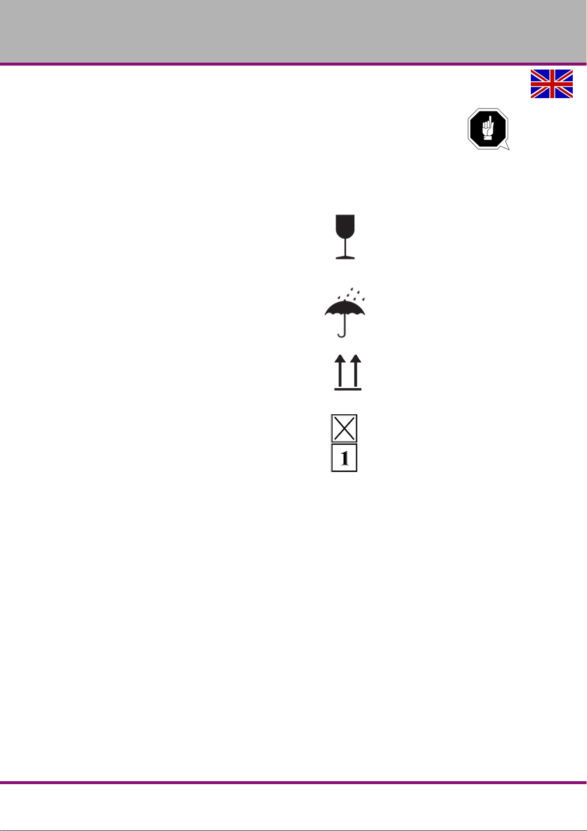
OPTIMUM
MASCHINEN - GERMANY
8.5 Storage
ATTENTION!
In case of wrong and improper storage electrical and mechanical machine components
might get damaged and destroyed.
Store packed and unpacked parts only under the intende d environmental conditions.
Follow the instructions and information on the transport case:
Fragile goods (Goods require careful handling)
Protect against moisture and humid environment
"Environmental conditions“ on page 18
Prescribed position of the packing case (Marking of
the top surface - arrows pointing to the top)
Maximum stacking height
Example: not stackable - do not stack a second
packing case
on top of the first one.
Consult Optimum Maschinen Germany GmbH if the machine and accessories are stored for
more than three months or are stored under different environmental conditions than those given
here.
8.6 Note regarding disposal / options to reuse:
Please dispose of your device environmentally friendly by disposing of scrap in a professional
way.
Please neither throw away the packaging nor the used machine later on, but dispose of them
according to the guidelines established by your city council/municipality or by the corresponding
waste management enterprise.
MF2 VarioGB
Version 1.3.0 dated 2016-12-16Page 74 Original operating instructions
Page 77
OPTIMUM
MASCHINEN - GERMANY
8.6.1 Decommissioning
CAUTION!
Immediately decommission used machines in order to avoid later misuse and
endangering of the environment or of persons.
Disconnect the plug from the power supply.
Cut the connection cable.
Remove all environmentally hazardous operating fluids from the used device.
If applicable remove batteries and accumulators.
Disassemble the machine if required into easy-to-handle and reusable assemblies
and component parts.
Supply the machine components and operating fluids to the provided disposal
routes.
8.6.2 Disposal of the packaging of new devices
All used packaging materials and packaging aids of the machine are recyclable and generally
need to be supplied to the material reuse.
The packaging wood can be supplied to the disposal or the reuse.
Any packaging components made of cardboard box can be chopped up and supplied to the
waste paper collection.
The films are made of polyethylene (PE) and the cu shion parts are made of polystyrene (PS).
These materials can be reused after reconditioning if they are forwarded to a collection station
or to the appropriate waste management enterprise.
Only forward the packaging materials correctly sorted to allow a direct reuse.
8.6.3 Disposing of the old device
INFORMATION
Please take care in your interest and in the interest of the environment that all component parts
of the machine are only disposed of in the intended and admitted way.
Please note that the electrical devices include lots of reusable materials as well as environmentally hazardous components. Account for separate and professional disposal of the component
parts. In case of doubt, please contact your municipal waste management. If appropriate, call
on the help of a specialist waste disposal company for the treatment of the material.
8.6.4 Disposal of electrical and electronic components
Please make sure that the electric al components are disposed of professionally and according
to the legal regulations.
The device includes electric and electronic components and must not be disposed of with the
rubbish.
According to the European directive 2002/96/EG regarding electrical and electronic used
devices and the execution of national rights used electrical tools and electrical machines need
to be collected separately and be supplied to an environmentally compatible reuse.
Being the machine operator you should obtain information regarding the authorized collection
or disposal system which applies for your company.
Please make sure that the batteries and/or accumulators are disposed of in a professiona l way
according to the legal regulations. Please only throw discharged batteries in the collection
boxes in shops or at municipal waste management companies.
Version 1.3.0 dated 2016-12-16 Page 75Original operating instructions
MF2 Vario GB
Page 78
OPTIMUM
MASCHINEN - GERMANY
8.6.5 Disposal of lubricants and coolants
ATTENTION!
Please imperatively make sure to dispose of the used coolant and lubricants in an
environmentally compatible way. Observe the disposal notes of your municipal waste
management companies.
INFORMATION
Used coolant emulsions and oils should not be mixed up since it is only possible to reuse used
oils which had not been mixed up without pre-treatment.
The disposal notes for the used lubr icants are made available by the manufacturer of the lubricants. If necessary, request the product-specific data sheets.
8.7 Disposal via municipal collection
Disposal of used electrical and electro nic com pone n ts
(Applicable in the countries of the European Union and other European countries with a separate collecting system for those devices).
The sign on the product or on its packing indicates that the product must not be handles as
common household waist, but that is needs to be delivered to a central collection point for recycling. Your contribution to the correct disposal of this product will protect the environment and
the health of your fellow men. The environment and the health are endangered by incorrect disposal. Recycling of material will help to reduce the consumption of raw materials. Your District
Office, the municipal waste collectio n station or the shop where you have bought the product
will inform you about the recycling of this product.
MF2 VarioGB
Version 1.3.0 dated 2016-12-16Page 76 Original operating instructions
Page 79

8.8 EC - Declaration of Conformity
Hallstadt, 2016-03-15
Kilian Stürmer
(CEO, General manager)
Machinery Directive 2006/42/EC Annex II 1.A
OPTIMUM
MASCHINEN - GERMANY
The manufacturer /
retailer:
hereby declares that the following product,
Type of machine: Milling-machine
Type designation: MF2 Vario
Serial number: _ __ __ __ __
Year of manufacture: 20__
Manual milling-machine with frequency converter and digital position display, for craft and industrial plants
which meets all the relevant provisions of the above mentioned Directive 2006/42/EC as well as the other
directives applied (below) including their amendments in force at the time of declaration. The following
other EU Directives have been applied: EMC Directive 2014/30/EU, Low Voltage Directive 2014/35/EU
The safety objective meet the requirement of EC Directive 2006/42/EC
The following harmonized standards were applied:
EN 13128:2001+A2:2009/AC:2010 Safety of machine tools - Milling machines (including boring machines)
EN 1037:1995+A1:2008 Safety of machinery - Prevention of unexpected start-up
EN ISO 14119 Safety of machinery - Interlocking devices associated with guards - Principles for design and
selection
EN 61800-5-1 Adjustable speed electrical power drive systems 2008-04 + correction 2
EN 61800-3:2012-09 Adjustable speed electrical power drive systems + correctio n 1
EN 50581:2012 Technical documentation for the assessment of electrical and electronic products with
respect to the restriction of hazardous substances
EN 60204-1:2006/AC: 2010 Safety of machinery - Electrical equipment of machines - Part 1: General
requirements
EN ISO 13849 - Safety of machinery - Safety-related parts of control systems
EN ISO 12100:2010 Safety of machinery - General principles for design - Risk assessment and risk reduc-
tion
EN ISO 13857:2008 Safety of machinery - Safety distances to prevent hazard zones being reached by
upper and lower limbs
Optimum Maschinen Germany GmbH
Dr.-Robert-Pfleger-Str. 26
D- 96103 Hallstadt
Responsible for documentation: Kilian Stürmer, phone: +49 (0) 951 96555 - 800
Address: Dr.-Robert-Pflege r-Str.26D - 96103 Hallstadt
Page 80

OPTIMUM
MASCHINEN - GERMANY
Index
A
Accident report ..................................................... 15
C
Cleaning ............................................................... 44
Control panel
Coolant pump
Cooling agent
Copyright
Cross table
Customer service
Customer service technician
........................................................ 28
....................................................... 29
....................................................... 41
.............................................................. 72
........................................................... 31
................................................. 47
................................ 47
D
Disinfection
Cooling lubricant tank
Disposal
Drill depth stop
............................................................... 76
..................................................... 38
..................................... 48
E
Earth leakage switch ............................................ 25
EC - declaration of conformity
Electrical system
EMERGENCY STOP push button
EMERGENCY-STOP
.................................................. 16
........................................... 43
.............................. 77
....................... 11
F
Feed motor ........................................................... 33
Feed reverse
Fine adjustment motor speed
First commissioning
........................................................ 41
............................... 38
............................................. 24
G
Gear switch .......................................................... 37
I
Installation ............................................................ 21
L
Load suspension point ......................................... 20
M
Main switch ..............................................11, 14, 30
Maintenance
Malfunctions
Mechanical maintenance work
......................................................... 44
......................................................... 70
............................. 15
O
Obligations
of the operating company
of the operator
Operation
............................................................. 27
................................................. 10
............................... 10
P
Prohibition, warning and mandatory labels .......... 12
Protective
equipment
Protective cover
Pulleys
....................................................... 13
............................................. 11, 28
.................................................................. 36
Q
Qualification of the personnel
Safety
................................................................ 9
R
Reasonably foreseeable misuses ...........................7
Repair
...................................................................44
Rotation direction switch
.......................................38
S
Safety devices ......................................................28
Safety instructions
Scope of delivery
Specialist dealer
Spindle brake
Spindle sleeve feed
Switch cabinet
..................................................5
..................................................20
...................................................47
........................................................38
..............................................39
.......................................................29
T
Technical data ......................................................17
Emissions
........................................................18
U
Using lifting equipment .........................................15
MF2 VarioGB
Version 1.3.0 dated 2016-12-16Page 78 Original operating instructions
 Loading...