

Page 1

OPTIMUM
MASCHINEN - GERMANY
Operating manual
Version 1.1.6
CNC-milling machine
GB
Page 2

OPTIMUM
MASCHINEN - GERMANY
Table of contents
1 Safety
1.1 Glossary of symbols .................................................................................................................................7
1.2 Safety instructions (warning notes)...........................................................................................................7
1.2.1 Classification of hazards ...............................................................................................................7
1.2.2 Other pictograms...........................................................................................................................8
1.3 Intended use .............................................................................................................................................9
1.4 Reasonably foreseeable misuses.............................................................................................................9
1.4.1 Avoiding misuses ........................................................................................................................10
1.5 Possible dangers caused by the CNC machine .....................................................................................11
1.6 Qualification of personnel .......................................................................................................................11
1.6.1 Target group................................................................................................................................11
1.6.2 Authorized personnel ..................................................................................................................12
1.7 Operator positions ..................................................................................................................................13
1.8 Safety devices .......................................................................................................................................13
1.8.1 Lockable main switch ..................................................................................................................14
1.8.2 EMERGENCY STOP push button...............................................................................................15
1.8.3 Control technical protection........................................................................................................15
1.8.4 Polycarbonate windows..............................................................................................................15
1.8.5 Prohibition, warning and mandatory labels .................................................................................16
1.9 Safety check ...........................................................................................................................................16
1.10 Personal protective equipment ...............................................................................................................17
1.11 Safety during operation...........................................................................................................................17
1.12 Safety during maintenance.....................................................................................................................18
1.13 Disconnecting and securing the CNC machine ......................................................................................18
1.13.1 Using lifting equipment ................................................................................................................19
1.13.2 Mechanical maintenance work ....................................................................................................19
1.14 Unattended Operation ............................................................................................................................19
1.15 Accident report........................................................................................................................................19
1.16 Electrical system.....................................................................................................................................20
1.17 Inspection deadlines ...............................................................................................................................20
1.18 Clamping devices for workpieces and tools..................................................................................
1.19 Environmental protection and water conservation..................................................................................20
2 Technical data
2.1 Electrical connection...............................................................................................................................21
2.2 Lubricant/coolant system ........................................................................................................................21
2.3 Compressed air supply..........................................................................................................................21
2.4 Dimensions .............................................................................................................................................21
2.5 Working area ..........................................................................................................................................22
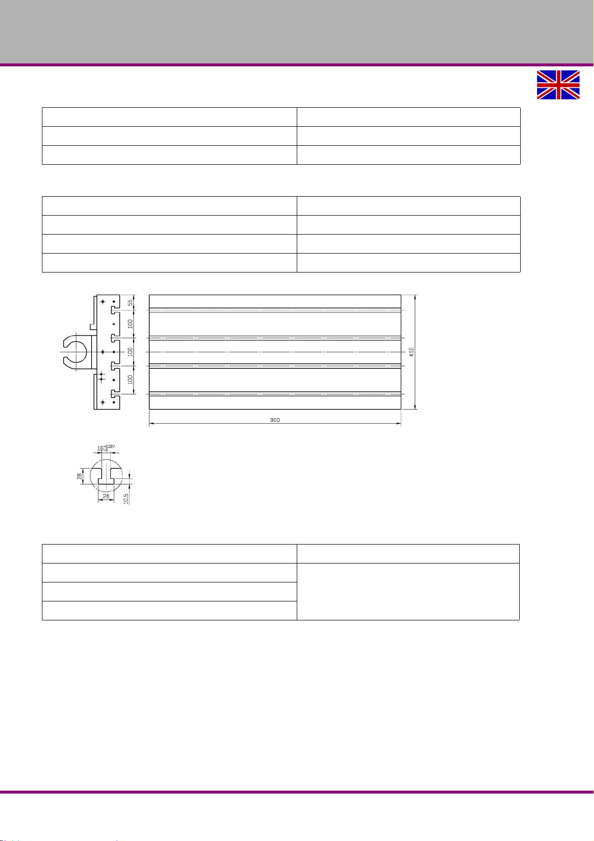
2.6 Milling table.............................................................................................................................................22
2.7 Feed drive axis .......................................................................................................................................22
2.8 Working area, traverse path ...................................................................................................................23
2.9 Standard tool changer carrousel............................................................................................................23
2.10 Optional tool changer double arm gripper .............................................................................................23
2.10.1 Standard milling spindle head .....................................................................................................23
2.10.2 milling spindle head with use of a CTS system ..........................................................................24
2.11 Spindle capacity......................................................................................................................................24
2.12 Environmental conditions- operation ......................................................................................................25
2.13 Environmental conditions - storage ......................................................................................................25
2.14 Optional coolant delivery through the spindle .........................................................................................25
2.14.1 Dimensions integrated unit 20 bar...............................................................................................25
2.14.2 Dimensions external unit 20 bar and 70 bar..............................................................................26
2.15 Emissions ...............................................................................................................................................27
..........20
F150GB
Version 1.1.6 dated 2014-10-16Page 2 Original operating instructions
Page 3

OPTIMUM
MASCHINEN - GERMANY
2.16 Tools and tool holding fixtures............................................................................................................... 27
3 Assembly and commissi on in g
3.1 Dimensions of the packing ..................................................................................................................... 28
3.2 Scope of delivery.................................................................................................................................... 28
3.3 Transport ................................................................................................................................................28
3.4 Storage................................................................................................................................................... 29
3.5 Installation plan F150 ............................................................................................................................30
3.6 Requirements regarding the installation site .......................................................................................... 30
3.7 Transportation to the installation site...................................................................................................... 31
3.7.1 Forklift truck................................................................................................................................. 31
3.7.2 Crane ..........................................................................................................................................32
3.8 Installation and assembly.......................................................................................................................33
3.8.1 Aligning the machine................................................................................................................... 33
3.8.2 Assembly of the coolant / lubricant tank and of the chip conveyor ............................................. 34
3.8.3 Assembly of the coolant / lubricant pumps..................................................................................35
3.8.4 Mounting the optional coolant through spindle............................................................................ 39
3.8.5 Mounting the heat exchanger on the switch cabinet ...................................................................40
3.8.6 Mounting the electronic handwheel............................................................................................. 40
3.9 Transport locking devices....................................................................................................................... 41
3.9.1 Transport locking device, 16-type tool changer .......................................................................... 41
3.9.2 Transport locking device, doors ..................................................................................................41
3.9.3 Transport locking device, axes....................................................................................................42
3.9.4 Mounting the telescopic covers...................................................................................................43
3.9.5 Corrosion protection.................................................................................................................... 43
3.9.6 Electrical connection ................................................................................................................... 43
3.9.7 Connection compressed air supply............................................................................................. 45
3.10 First commissioning................................................................................................................................ 46
3.10.1 Fill up coolant..............................................................................................................................46
3.11 Refill central lubrication system..............................................................................................................47
3.11.1 Functional test and controls ........................................................................................................ 47
3.11.2 Warming up the machine ............................................................................................................ 48
3.11.3 Passwords................................................................................................................................... 48
3.11.4 Data backup on the control .........................................................................................................49
4 General information about CNC
4.1 Compensation of geometry ....................................................................................................................50
4.2 Coordinate systems on CNC machine tools........................................................................................... 50
4.2.1 Cartesian coordinate system.......................................................................................................50
4.2.2 Polar coordinate system..............................................................................................................51
4.2.3 Machine coordinate system ........................................................................................................ 51
4.2.4 Workpiece coordinate system ..................................................................................................... 51
4.2.5 Rotary axes and secondary axes................................................................................................ 52
4.3 NC mathematics..................................................................................................................................... 52
4.3.1 Basics of the coordinate calculation............................................................................................ 52
4.3.2 Parameters of a triangle.............................................................................................................. 52
4.3.3 Angle on a triangle ...................................................................................................................... 52
4.4 Trigonometric functions .......................................................................................................................... 53
5 User interface, machine control panel
5.1 Screen arrangement...............................................................................................................................54
5.2 Key definition of the CNC full keyboard.................................................................................................. 55
5.2.1 Keys and key combinations on the control panel ........................................................................ 55
5.3 Controls on the machine control panel................................................................................................... 64
5.3.1 Key switch..................................................................................................................................69
6Operation
6.1 Safety .....................................................................................................................................................71
6.2 Control and indicating elements ............................................................................................................ 71
Version 1.1.6 dated 2014-10-16 Page 3Original operating instructions
F150 GB
Page 4

OPTIMUM
MASCHINEN - GERMANY
6.2.1 Operating the handwheel for manual travelling ..........................................................................72
6.3 Switching on the CNC machine..............................................................................................................73
6.4 Switching off the CNC machine..............................................................................................................74
6.5 First insertion of a tool ...........................................................................................................................74
6.6 Insert tool ................................................................................................................................................74
6.7 Manual operation of the tool changer ....................................................................................................76
6.7.1 Manual operation of the 16-type tool changer .............................................................................76
6.7.2 Manual operation of the 24-type tool changer .............................................................................76
6.7.3 Quit the ATC-Service mode .......................................................................................................76
6.8 Setting.....................................................................................................................................................77
6.8.1 Clamping workpiece and setting workpiece datum .....................................................................77
6.8.2 Setting resp. measuring tool........................................................................................................78
6.9 Operational modes .................................................................................................................................80
6.10 Programming ..........................................................................................................................................80
6.11 Start program..........................................................................................................................................80
6.12 Operating the central lubrication system ................................................................................................81
6.13 Data interfaces and current collection ....................................................................................................82
6.14 Executing from an external position........................................................................................................83
7 M - code list, M functions
7.1 G function according to PAL...................................................................................................................85
8 Notes, messages and error messages
9 SINUMERIK 828 D
10 Maintenance
10.1 Operating material ..................................................................................................................................93
10.1.1 Machine lubricants ......................................................................................................................93
10.1.2 Cooling lubricants........................................................................................................................93
10.2 Safety......................................................................................................................................................94
10.2.1 Preparation..................................................................................................................................95
10.2.2 Restarting ....................................................................................................................................95
10.3 Repair .....................................................................................................................................................95
10.3.1 Customer service technician .......................................................................................................95
10.4 Inspection and maintenance...................................................................................................................96
10.4.1 Disassembly of the cooling lubricant tank .................................................................................100
10.4.2 Cleaning and replacing of the polycarbonate windows ............................................................100
10.4.3 Cleaning electrical cabinet ........................................................................................................101
10.4.4 Refill the compressed air oiler ...................................................................................................101
10.4.5 Drain compressed air service unit .............................................................................................102
10.4.6 Air purge...................................................................................................................................102
10.4.7 Replacing of compressed air filter .............................................................................................102
10.4.8 Refill central lubrication system.................................................................................................103
10.4.9 Fill up coolant ............................................................................................................................103
10.4.10Cleaning of oil tank and oil filters on the central lubrication system .........................................104
10.5 Optional CTS system............................................................................................................................105
10.5.1 Cleaning and replacing the filters on the external CTS system.................................................106
10.5.2 Cleaning and replacing the filters on the internal CTS system..................................................107
10.6 Cooling lubricants and tanks.................................................................................................................108
10.6.1 Inspection plan for water-mixed cooling lubricants....................................................................109
10.7 Network.................................................................................................................................................110
10.8 Data interfaces and current collection ..................................................................................................110
10.9 Installation and network connection......................................................................................................110
10.10 Executing from an external position......................................................................................................115
10.11 Adjusting the amount of oil at the central lubrication ...........................................................................116
11 Mechanische Ersatzteile - Mechanical Spare parts
11.1 Ersatzteilbestellung - Ordering spare parts ..........................................................................................118
F150GB
Version 1.1.6 dated 2014-10-16Page 4 Original operating instructions
Page 5

OPTIMUM
MASCHINEN - GERMANY
11.2 Elektrische Ersatzteile - Electrical spare parts ..................................................................................... 118
11.3 Schaltplan - Wiring diagram .................................................................................................................118
11.4 Fräskopf - Milling head ......................................................................................................................... 119
11.5 Säule - Column.....................................................................................................................................121
11.6 Maschinenunterbau - Machine stand ................................................................................................... 123
11.7 Frästisch - Milling table 1- 2 ................................................................................................................. 125
11.8 Frästisch - Milling table 2- 2 ................................................................................................................. 127
11.9 Baugruppe X-Achse - Assembly X- Axis ..............................................................................................128
11.10 Baugruppe Y-Achse - Assembly Y- Axis..............................................................................................130
11.11 Baugruppe Z-Achse - Assembly Z- Axis ..............................................................................................132
11.12 Maschinengehäuse - Machine housing ................................................................................................ 134
11.13 Späneförderer - Chip convejor ............................................................................................................. 135
11.14 16-fach Werkzeugwechsler - 16-station tool changer .......................................................................... 136
11.14.1Werkzeugwechsler 1-4 - Tool changer 1-4 .............................................................................. 136
11.14.2Werkzeugwechsler 2-4 -Tool changer 2-4 ............................................................................... 138
11.14.3Werkzeugwechsler 3-4 -Tool changer 3-4 ............................................................................... 140
11.14.4Werkzeugwechsler 4-4 -Tool changer 4-4 ............................................................................... 141
11.15 Optionaler 24-fach Werkzeugwechsler - Optional 24-station tool changer .......................................... 143
11.15.1Werkzeugwechsler 1 von 5 - Tool changer 1 of 5 .................................................................... 143
11.15.2Werkzeugwechsler 2 von 5 - Tool changer 2 of 5 .................................................................... 144
11.15.3Werkzeugwechsler 3 von 5 - Tool changer 3 of 5 .................................................................... 145
11.15.4Werkzeugwechsler 4 von 5 - Tool changer 4 of 5 .................................................................... 146
11.15.5Werkzeugwechsler 5 von 5 - Tool changer 5 of 5 .................................................................... 147
11.16 Integriertes Kühlaggregat 20 bar - Integrated cooling unit 20 bar ........................................................149
11.17 Externes Kühlaggregat 20 bar - External cooling unit 20 bar ...............................................................150
11.18 Externes Kühlaggregat 70 bar - External cooling unit 70 bar ...............................................................151
11.19 EC - Declaration of Conformity............................................................................................................. 152
12 EC - Declaration of Conformity SIEMENS
13 Appendix
13.1 Copyright ..............................................................................................................................................154
13.2 Changes ...............................................................................................................................................154
13.3 Product follow-up..................................................................................................................................154
13.4 Liability claims for defects / warranty.................................................................................................... 155
13.5 Advice for disposal / Options of re-use................................................................................................. 155
13.5.1 Decommissioning...................................................................................................................... 156
13.5.2 Disposal of the packaging of new devices ................................................................................156
13.5.3 Disposal of the machine............................................................................................................ 156
13.5.4 Disposal of electrical and electronic components .....................................................................156
13.5.5 Disposal of lubricants and coolants........................................................................................... 157
13.6 Disposal via municipal collection.......................................................................................................... 157
13.7 RoHS, 2002/95/EC............................................................................................................................... 157
13.8 Re-export.............................................................................................................................................. 158
13.9 Terminology/Glossary .......................................................................................................................... 159
13.10 Change information operating manual ................................................................................................. 160
Preface
Dear customer,
Thank you very much for purchasing a product made by OPTIMUM.
OPTIMUM metal working machines offer a maximum of quality, technically optimum solutions and convince
by an outstanding price performance ratio. Continuous enhancements and product innovations guarantee
state-of-the-art products and safety at any time.
Version 1.1.6 dated 2014-10-16 Page 5Original operating instructions
F150 GB
Page 6

OPTIMUM
MASCHINEN - GERMANY
Before commissioning the machine please thoroughly read these operating instructions and get familiar with
the machine. Please also make sure that all persons operating the machine have read and understood the
operating instructions beforehand.
Keep these operating instructions in a safe place nearby the machine.
Information
The operating instructions include indications for safety-relevant and proper installation, operation and
maintenance of the machine. The continuous observance of all notes included in this manual guarantee the
safety of persons and of the machine.
The manual determines the intended use of the machine and includes all necessary information for its economic operation as well as its long service life.
In the paragraph "Maintenance" all maintenance works and functional tests are described which the operator must perform in regular intervals.
The illustration and information included in the present manual can possibly deviate from the current state of
construction of your machine. Being the manufacturer we are continuously seeking for improvements and
renewal of the products. Therefore, changes might be performed without prior notice. The illustrations of the
machine may be different from the illustrations in these instructions with regard to a few details. However,
this does not have any influence on the operability of the machine.
Therefore, no claims may be derived from the indications and descriptions. Changes and errors are reserved!
Your suggestion with regard to these operating instructions are an important contribution to optimising our
work which we offer to our customers. For any questions or suggestions for improvement, please do not
hesitate to contact our service department.
If you have any further questions after reading these operating instructions and you are not able to solve your
problem with a help of these operating instructions, please contact your specialised dealer or directly the
company OPTIMUM.
Optimum Maschinen Germany GmbH
Dr.- Robert - Pfleger - Str. 26
D-96103 Hallstadt
Mail: [email protected]
Internet: www.optimum-maschinen.
F150GB
Version 1.1.6 dated 2014-10-16Page 6 Original operating instructions
Page 7
OPTIMUM
MASCHINEN - GERMANY
1 Safety
This part of the operating instructions
explains the meaning and use of the warning notices included in these operating instruc-
tions,
defines the intended use of the CNC machine,
points out the dangers that might arise for you or others if these instructions are not
observed,
informs you about how to avoid dangers.
In addition to these operation instructions, please observe
the applicable laws and regulations,
the legal regulations for accident prevention,
the prohibition, warning and mandatory signs as well as the warning labels on the CNC
machine.
Always keep this documentation close to the CNC machine.
1.1 Glossary of symbols
provides further instructions
calls on you to act
enumerations
1.2 Safety instructions (warning notes)
1.2.1 Classification of hazards
We classify the safety warnings into various levels. The table below gives an overview of the
classification of symbols (ideogram) and the warning signs for each specific danger and its
(possible) consequences.
Symbol Warning alert Definition / consequence
DANGER!
WARNING!
CAUTION!
ATTENTION!
INFORMATION
Impending danger that will cause serious injury or death to people.
A danger that might cause severe injury to the personnel or can lead to
death.
Danger or unsafe procedure that might cause injury to people or damage to
property.
Situation that could cause damage to the CNC machine and product and
other types of damage.
No risk of injury to people.
Application tips and other important or useful information and notes.
No dangerous or harmful consequences for people or objects.
Safety
Version 1.1.6 dated 2014-10-16 Page 7Original operating instructions
F150 GB
Page 8
OPTIMUM
MASCHINEN - GERMANY
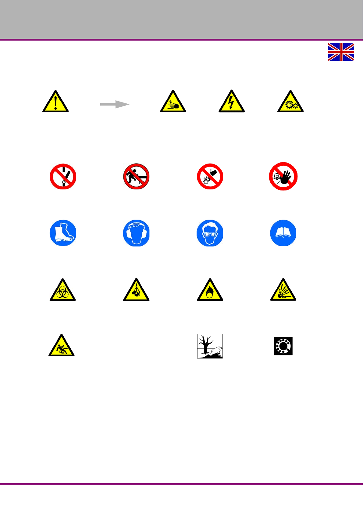
In case of specific dangers, we replace the pictogram with
general danger with a warning of injury of hands, hazardous electrical
voltage,
rotating parts.
1.2.2 Other pictograms
Activation forbidden! Stepping into the machine
prohibited!
Use protective boots! Use ear protection! Wear protective glasses! Read the operating instruc-
Forbidden to extinguish
with water!
Access forbidden!
tion!
Warning biological hazard! Warning suspended loads! Warning of oxidizing mate-
rials!
Warning danger of slipping! Protect the environment! Contact address
Warning of explosive!
F150GB
Version 1.1.6 dated 2014-10-16Page 8 Original operating instructions
Safety
Page 9

OPTIMUM
MASCHINEN - GERMANY
1.3 Intended use
WARNING!
In the event of improper use, the CNC machine
will endanger personnel,
the CNC machine and other material property of the operating company will be
endangered,
the correct function of the CNC machine may be affected.
The CNC machine is designed and manufactured to be used for milling and drilling cold metals
or other non-flammable materials or materials that do not constitute a health hazard by using
commercial milling and drilling tools.
Using this machine it is possible to perform dry processing as well as processing by using cooling lubricants.
The limit values of the balances of the tools need to be observed.
fixtures“ on page 27
The CNC machine must only be installed and operated in a dry and well-ventilated place.
The CNC machine is designed and manufactured to be used in environments where there is no
potential danger of explosion.
approval of the company Optimum Maschinen Germany GmbH then the drilling-milling machine
is being used improperly.
We will not be held liable for any damages resulting from any operation which is not in accordance with the intended use.
We expressly point out that the guarantee or CE conformity will expire due to any constructive
technical or procedural changes which had not been performed by the company Optimum
Maschinen Germany GmbH.
It is also part of intended use that you
observe the limits of performance of the CNC-machine,
the operating manual is observed,
the inspection and maintenance instructions are observed.
"Cooling lubricants“ on page 93
"Tools and tool holding
Intended useIf the CNC machine is used in any way other than described above, modified without the
WARNING!
Severe injuries due to improper use.
It is forbidden to make any modifications or alternations to the operation values of the
CNC machine. They could endanger employees and cause damage to the CNC machine.
1.4 Reasonably foreseeable misuses
Any other use as the one determined under the "Intended use" or any use beyond the
described use shall be deemed as not in conformity and is forbidden.
Any other use has to be discussed with the manufacturer.
It is only allowed to process metal, cold and non-inflammable materials with the millingmachine.
In order to avoid misuses it is necessary to read and understand the operating instructions
before the first commissioning.
The operators must be qualified.
Safety
Version 1.1.6 dated 2014-10-16 Page 9Original operating instructions
F150 GB
Page 10
OPTIMUM
MASCHINEN - GERMANY
1.4.1 Avoiding misuses
Use of suitable cutting tools.
Adapting the speed adjustment and feed to the material and workpiece.
Clamp workpieces firmly and vibration-free.
ATTENTION!
The workpiece is always to be fixed by a machine vice, jaw chuck or by another
appropriate clamping tool such as for the clamping claws.
WARNING!
Risk of injury caused by workpieces flying off.
Clamp the workpiece in the machine vice. Make sure that the workpiece is firmly clamped in the
machine vice resp. that the machine vice is firmly clamped on the machine table.
Use cooling and lubricating agents to increase the durability of the tool and to improve the
surface quality.
Clamp the cutting tools and workpieces on clean clamping surfaces.
Sufficiently lubricate the machine.
Correctly adjust the bearing clearance and the guidings.
It is recommended:
Insert the drill in a way that it is exactly positioned between the three clamping jaws of the
quick action chuck.
Clamp and mills by means of the collet chuck and the corresponding collets.
Clamp end face mills by means of shell end mill arbors.
When drilling make sure that
the suitable speed is set depending on the diameter of the drill,
the pressure must only be such that the drill can cut without load
in case of too strong pressure the drill will get worn early or even might break resp. get
jammed in the hole. If the drill gets jammed immediately stop the main motor by pressing
the emergency stop button,
for hard materials, e.g. steel, use commercial cooling / lubricating agents,
generally always drive the turning spindle out of the workpiece.
ATTENTION!
Do not use the quick action drill chuck for milling tools. Never clamp a milling cutter into
a quick action drill chuck. Use a collet chuck with collets for the end mill.
When milling make sure that
the corresponding cutting speed is selected,
for workpieces with normal strength values, e.g. steel 18-22 m/min,
for workpieces with high strength values 10-14 m/min,
the pressure is selected in a way that the cutting speed remains constant,
for hard materials commercial cooling / lubricating agents are used.
F150GB
Version 1.1.6 dated 2014-10-16Page 10 Original operating instructions
Safety
Page 11

OPTIMUM
MASCHINEN - GERMANY
1.5 Possible dangers caused by the CNC machine
The CNC machine has undergone a safety inspection.. The construction and type are state of
the art.
Nevertheless, there is a residual risk as the CNC machineoperates with
rotating parts,
electrical voltage and currents,
compressed air,
rapid moves.
We have used construction resources and safety techniques to minimize the health risk to personnel resulting from these hazards.
If the CNCmachine is used and maintained by the personnel who are not duly qualified, there
may be a risk resulting from incorrect or unsuitable maintenance of the CNCmachine.
INFORMATION
Everyone involved in the assembly, commissioning, operation and maintenance must
be duly qualified,
strictly follow these operating instructions.
In the event of improper use
there may be a risk to the personnel,
there may be a risk to the CNC machine and other material values,
the correct function of the CNC machine may be affected.
Always switch off the CNC-machine and disconnect it from the mains if you perform cleaning or
maintenance works.
WARNING!
The CNC machine may only be used with the safety devices activated. Disconnect the
CNC-machine immediately, whenever you detect a failure in the safety devices or when
they are not fitted!
All additional parts of the machine which had been added by the customer need to be
equipped with the prescribed safety devices.
This is your responsibility being the operating company!
13
"Safety devices“ on page
1.6 Qualification of personnel
1.6.1 Target group
This manual is addressed to
the operating companies,
operators having sufficient specialist knowledge,
the maintenance personnel.
Therefore, the warning notes refer to both operation and maintenance of the CNC machine.
Determine clearly and explicitly who will be responsible for the different activities on the CNCmachine (operation, setting up, maintenance and repair). Please note the name of the responsible person into an operators´s log.
INFORMATION
Unclear responsibilities constitute a safety risk!
Always lock the main switch after switching off the CNC-machine. This will prevent it from being
used by unauthorized persons.
The qualifications of the personnel for the different tasks are mentioned below:
Safety
Version 1.1.6 dated 2014-10-16 Page 11Original operating instructions
F150 GB
Page 12

OPTIMUM
MASCHINEN - GERMANY
Operator
The operator has been instructed by the operating company regarding the assigned tasks and
possible risks in case of improper behaviour. Any tasks which need to be performed beyond the
operation in the standard mode must only be performed by the operator if it is indicated in these
instructions and if the operating company expressively commissioned the operator.
Electrical specialist
Due to professional training, knowledge and experience as well as knowledge of respective
standards and regulations the electrical specialist is able to perform work on the electrical system and recognise and avoid any possible dangers.
The electrical specialist is specially trained for the working environment in which he is working
and knows the relevant standards and regulations.
Qualified personnel
Due to their professional training, knowledge and experience as well as their knowledge of relevant regulations the qualified personnel is able to perform the assigned tasks and to recognise
and avoid any possible dangers themselves.
Instructed person
Instructed personnel were instructed by the operating company about the assigned tasks and
any possible risks in case of improper behaviour.
1.6.2 Authorized personnel
INFORMATION
For working on the CNC machine sufficient expertise is required. No one must work on
the machine without having the necessary education, not even for a short while.
As aid for training and operation we recommend to use the CNC-Software SinuTrain.
SinuTrain made by Siemens is the perfect software supplement for the CNC-machine F150 of
OPTIMUM.
This training software supports the rapid training for the operation of the control Sinumerik Siemens 828D. Employees having little CNC experience can learn the basics of the DIN programming by using SinuTrain and are finally able to write and test programs using Siemens 828D
cycles.
Please find SinuTrain and further information on the website of Siemens.
WARNING!
Inappropriate operation and maintenance of the CNC machine constitutes a danger for
the personnel, objects and the environment.
Only authorized personnel may operate the CNC machine!
Persons authorized to operate and maintain should be trained technical personnel and
instructed by the ones who are working for the operating company and for the manufacturer.
Obligations of the operating company
train the personnel,
instruct the personnel in regular intervals (at least once a year) on
- all safety standards that apply to the CNC machine,
- the operation of the CNC machine,
- accredited technical guidelines,
- possible emergency situations,
check personnel‘s state of knowledge,
document training/instruction in a operation book,
F150GB
Obligations of
the operating
company
Safety
Version 1.1.6 dated 2014-10-16Page 12 Original operating instructions
Page 13

OPTIMUM
MASCHINEN - GERMANY
require personnel to confirm participation in training/instructions by means of a signature,
check whether the personnel is working safety- and risk-conscious and observe the operat-
ing instructions.
define and document the inspection deadlines for the machine in accordance with § 3 of the
Factory Safety Act and perform an operational risk analysis in accordance with § 6 of the
Work Safety Act.
Obligations of the operator
be specially trained in handling and programming the CNC-machine,
know and understand the program sequence and which effects the individual process
parameters will have,
keep an operator‘s log,
before taking the machine in operation
- have read and understood the operating manual,
- be familiar with all safety devices and instructions.
For work on the following CNC machine parts there are additional requirements:
Electric components or operating materials: Must only be performed by a qualified electri-
cian or person working under the instructions and supervision of a qualified electrician.
1.7 Operator positions
The operator position is in front of the CNC-machine at the sight window or on the machine
control panel.
1.8 Safety devices
Use the CNC machine only with properly functioning safety devices.
Stop the CNCmachine immediately if there is a failure on the safety device or if it is not functioning for any reason.
It is your responsibility!
If a safety device has been activated or has failed, the CNC machinemust only be used if you
have removed the cause of the failure,
have verified that there is no danger resulting for the personnel or objects.
Obligations of
the operator
Additional
requirements
regarding the
qualification
WARNING!
If you bypass, remove or override a safety device in any other way, you are endangering
yourself and other persons working on the CNC machine. The possible consequences
are:
injuries due to tools, workpieces or fragments hereof which are flying off at high
speed,
contact with rotating or moving parts,
fatal electrocution,
pulling-in of clothes.
The CNC machine includes the following safety devices:
a lockable main switch,
One EMERGENCY STOP push-button on the machine control panel and on the electronic
handwheel,
A locked, separating protective equipment around the CNC-milling machine with sight win-
dows made of break-proof Makrolon.
Locking switch on the separating safety devices.
Safety
F150 GB
Version 1.1.6 dated 2014-10-16 Page 13Original operating instructions
Page 14
OPTIMUM
MASCHINEN - GERMANY
1.8.1 Lockable main switch
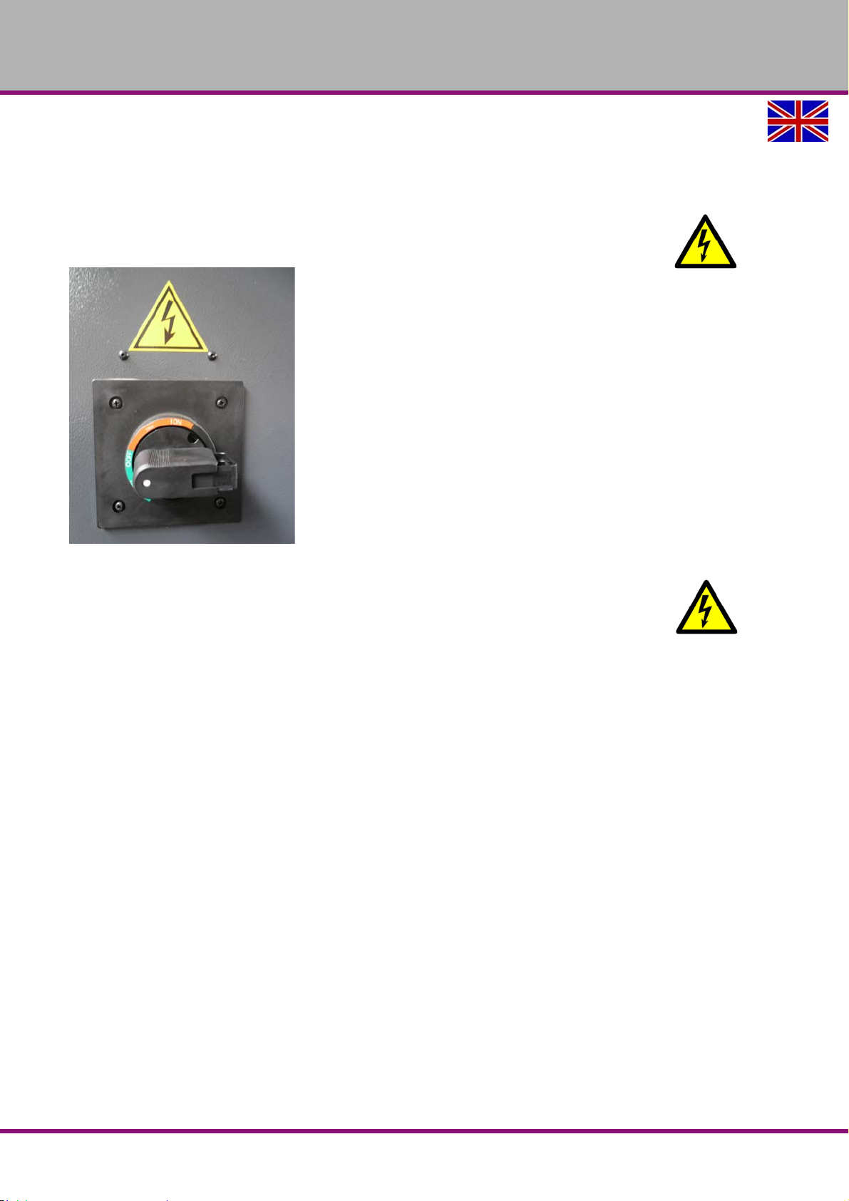
In the position " 0 " the lockable main switch can be secured against accidental or non-authorized switching-on by means of a padlock.
When the main switch is switched-off, the power supply is interrupted.
Except in the areas marked by the pictogram in the margin. In these areas there might be voltage, even if the main switch is switched-off.
Img.1-1: Main switch
WARNING!
Dangerous voltage even if the main switch is switched-off.
In the areas marked by the pictogram in the margin, there might be live parts, even if the main
switch is switched off.
F150GB
Version 1.1.6 dated 2014-10-16Page 14 Original operating instructions
Safety
Page 15
OPTIMUM
MASCHINEN - GERMANY
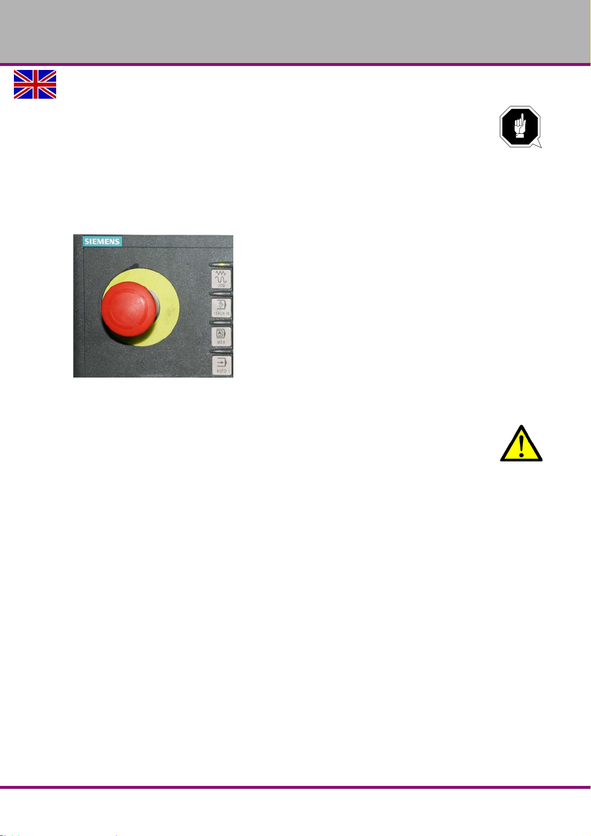
1.8.2 EMERGENCY STOP push button
ATTENTION!
The EMERGENCY STOP push button immediately stops the operation of the CNC
machine.
Press the EMERGENCY STOP push button only if there is a risk! If this button is
actuated in order to switch off the CNC machine in the standard operation the tool or
workpiece might get damaged.
After having actuated the EMERGENCY STOP, turn the knob of the particular push button to
the right in order to restart the machine.
Img.1-2: Emergency-stop push button
1.8.3 Control technical protection
WARNING!
If you bypass a controller you endanger yourself and other persons working on the CNC
machine.
injuries due to tools, workpieces or fragments hereof which are flying off at high
speed,
contact with rotating parts,
fatal electrocution,
pulling-in of clothes.
If you bypass a controller in exceptional cases (e.g. during electrical repairs) short term you
must continuously monitor the CNC machine during this time.
1.8.4 Polycarbonate windows
Polycarbonate windows which have a safety-critical function with respect to ejected parts, must
be visual inspected by the customer responsible personnel at regular intervals to guarantee the
operational safety of the CNC machine.
Polycarbonate windows are subject to an aging process and are classified as wear parts.
The aging of polycarbonate windows can not be detected by visual inspection. It is therefore
necessary to replace the polycarbonate windows after a certain time.
Prolonged exposure from polycarbonate windows to cutting fluids can lead to accelerated ageing, i.e. deterioration of the mechanical properties (brittleness). Coolant vapours, detergents,
greases and oils or other corrosive substances from the operator side can also lead to a deterioration of the polycarbonate windows. The result is a reduced parts retentivity of the polycarbonate windows.
"Cleaning and replacing of the polycarbonate windows“ on page 100
Safety
Version 1.1.6 dated 2014-10-16 Page 15Original operating instructions
F150 GB
Page 16
OPTIMUM
MASCHINEN - GERMANY
1.8.5 Prohibition, warning and mandatory labels
INFORMATION
All warning and mandatory labels must be legible. Check them regularly.
1.9 Safety check
Check the CNC machine at least once per shift. Inform the person responsible immediately of
any damage, defects or changes in the operating function.
Check all safety devices
at the beginning of each shift (when the machine is operated continuously),
once per day (during one-shift operation),
once per week (when operated occasionally),
after all maintenance and repair work.
Check that prohibition, warning and information signs and the labels on the CNC machine
are legible (clean them, if necessary),
are complete (replace them, if necessary).
INFORMATION
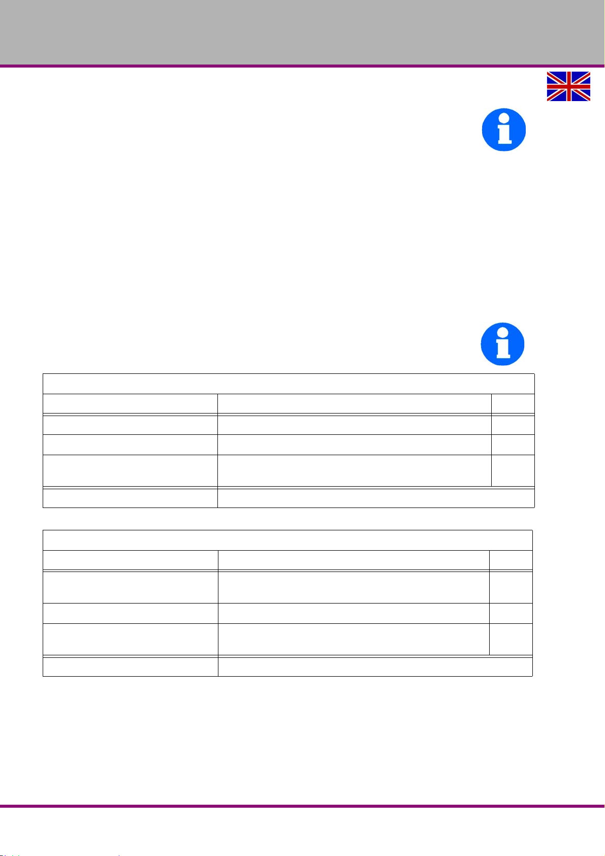
Use the following table in order to organize the checks.
General check
Equipment Check OK
Protective housing Switching function, firmly bolted and not damaged
Signs, Markings Installed and legible
Sight window Check for mechanical damage (scratches, cracks)
"Polycarbonate windows“ on page 15
Date: checked by (signature):
Functional check
Equipment Check OK
EMERGENCY STOP
button
Switch cabinet cooling The cabinet cooling must be running.
Separating protective equipment
around the CNC machine
Date: checked by (signature):
After actuating an EMERGENCY STOP button the CNC
machine must be switched off.
If the protective equipment is open it must not be possible to start program.
F150GB
Version 1.1.6 dated 2014-10-16Page 16 Original operating instructions
Safety
Page 17
OPTIMUM
MASCHINEN - GERMANY
1.10 Personal protective equipment
For certain work personal protective equipment is required.
Protect your face and eyes: Wear a safety helmet with facial protection when performing works
where your face and eyes are exposed to hazards.
Use protective gloves when handling pieces or tools with sharp edges.
Use safety shoes when you assemble, disassemble or transport heavy components.
Use ear protection if the noise level (emission) in the workplace exceeds 80 dB (A).
Before starting work make sure that the required personal protective equipment is available at
the work station.
CAUTION!
Dirty or contaminated personnel protective equipment can cause illnesses. Clean it each
time after use and at least once a week.
1.11 Safety during operation
WARNING!
Before activating the CNC machine ensure that this will neither endanger other persons
nor cause damage to equipment.
Avoid any risky working practices:
The instructions mentioned in these operating instructions have to be strictly observed dur-
ing assembly, operation, maintenance and repair.
Do not work on the CNC machine, if your concentration is reduced, for example, because
you are taking medication.
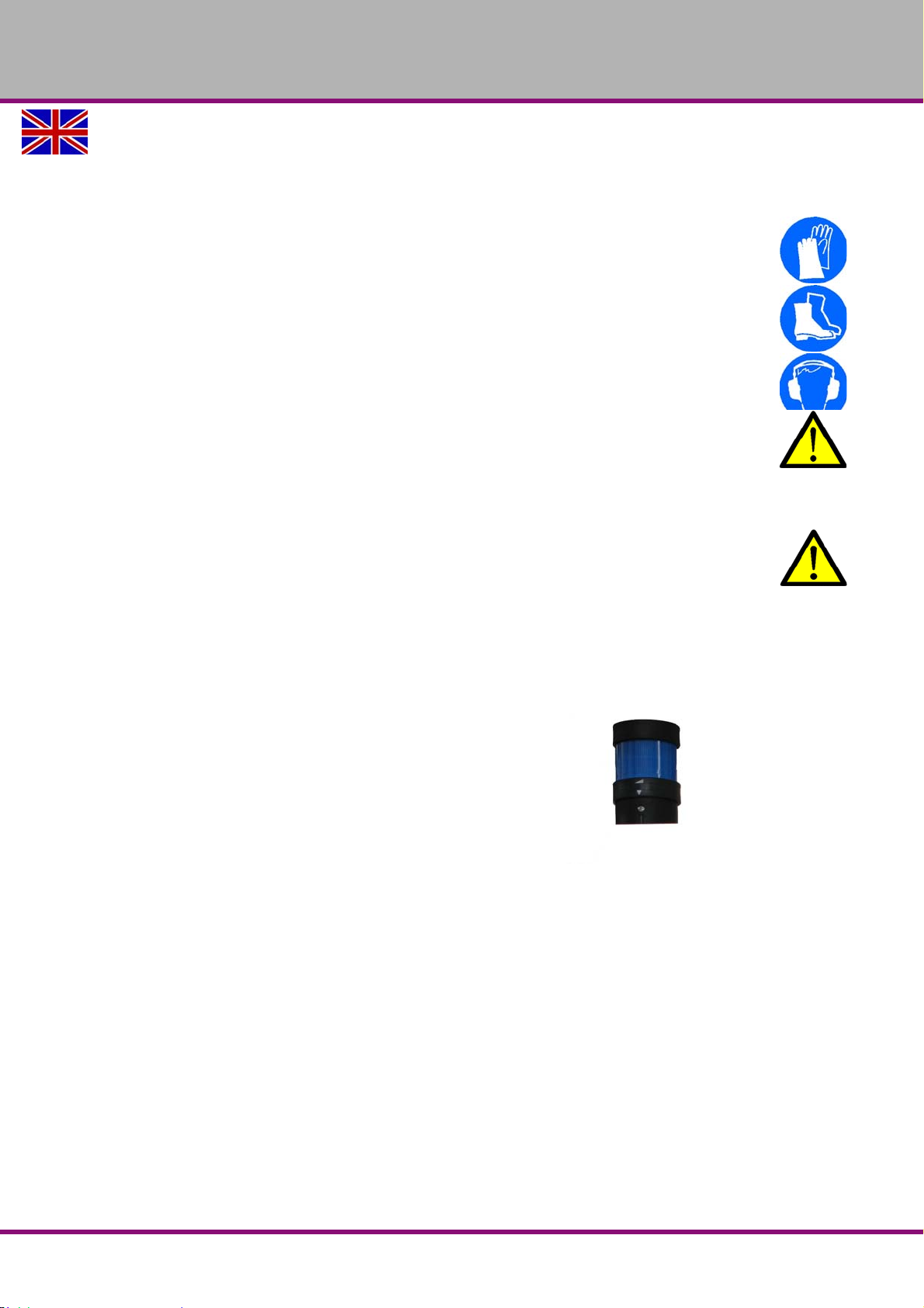
Stay on the CNC machine until the program is termi-
nated.
The running program can be identified by means of
the signal lamp.
- Continuous light: Program runs.
- Flashing light: NC stop or program hold.
Img.1-3: Signal lamp
Safely and firmly clamp the workpiece before switching on the CNC machine.
Never change the dosing of the coolant supply during operation.
Never open the sliding door of the separating protective unit when the CNC-program is run-
ning.
Safety
Version 1.1.6 dated 2014-10-16 Page 17Original operating instructions
F150 GB
Page 18
OPTIMUM
MASCHINEN - GERMANY
WARNING!
When chipping magnesia materials (aluminium-/magnesium alloys) spontaneously
inflammable or explosive particles (powder, dust, chips) might be generated which might
result in a fire and/or an explosion (deflagration).
Magnesium is designated as a dangerous material in the list of dangerous materials and
preparations according to §4a of Ordinance of Hazardous Substances.
In case of a fire with magnesium only use appropriate and admitted extinguishing
agents. Never extinguish using water. If you extinguish burning magnesium with water it
might lead to dangerous reactions (detonating gas). Water would be decomposed in its
components hydrogen (H) and oxygen (O).
Only the following extinguishing agents are admitted:
solid extinguishing agent of the fire class D (fires of metals)
dry covering salts for magnesium
a mixture of sand and cast chips
argon (Ar) or nitrogen (N
If fine mist and smoke is generated in the working room, suction unites need to provided
in order to avoid the accumulation of ignitable mixtures and emissions.
We provide information about the specific dangers when working with and on the CNC machine
in the descriptions for these types of work.
)
2
1.12 Safety during maintenance
Inform the operators in good time about any maintenance and repair works.
Report all safety relevant changes and performance details of the multifunctional CNCmachine. Document all changes, have the operating instructions updated accordingly and train
machine operators.
1.13 Disconnecting and securing the CNC machine
Turn off the main switch of the CNC machine before starting any maintenance or repair work.
Use a padlock to prevent the switch from being turned on without authorization and keep the
key in a safe place.
All machine parts as well as all dangerous voltages are switched off.
Only the positions which are marked with the pictogram on the side constitute an exception.
These positions may be live even if the main switch is switched off.
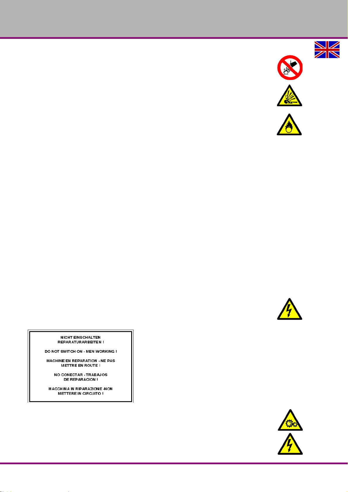
Attach a warning sign on the CNCmachine.
Img.1-4: Warning sign
WARNING!
Live parts and machine part movements can lead to severe injury to you or other s!
Proceed with extreme care if you cannot switch off
the CNC machine by turning off the main switch due to required works (e.g. functional
control).
F150GB
Version 1.1.6 dated 2014-10-16Page 18 Original operating instructions
Safety
Page 19

OPTIMUM
MASCHINEN - GERMANY
1.13.1 Using lifting equipment
WARNING!
The use of unstable lifting and load suspension equipment that might break under load
can cause severe injuries or even death. Observe the accident prevention regulations
issued by your Employers Liability Insurance Association or other supervisory
authorities responsible for your company.
Check that the lifting equipment and load-suspension gears are of sufficient load
capacity and are in perfect condition.
Fasten the loads properly.
Never walk under suspended loads!
1.13.2 Mechanical maintenance work
Remove or install protection safety devices before starting or after completing any maintenance work; these include:
covers,
safety indications and warning signs,
earth (ground) connections.
If you remove protective or safety devices, re-fit them immediately after the completing the
work.
Check if they are working properly!
1.14 Unattended Operation
CNC machines are designed to operate unattended. However, your machining process may not
be safe to operate unmonitored. As it is the shop owner’s responsibility to set up the machine
safely and use best practice machining techniques, it is also their responsibility to manage the
progress of these methods. The machining process must be monitored to prevent damage if a
hazardous condition occurs.
For example, if there is the risk of fire due to the material machined, then you must install an
appropriate fire suppression system to reduce the risk of harm to personnel, equipment and the
building. Contact a specialist to install monitoring tools before machines are allowed to run
unattended.
It is especially important to select monitoring equipment that can immediately perform an appropriate action without human intervention to prevent an accident, should a problem be detected.
1.15 Accident report
Inform your supervisors and Optimum Maschinen Germany GmbH immediately in the event of
accidents, possible sources of danger and any actions which almost led to an accident (near
misses).
There are many possible causes for "near misses".
The sooner they are notified, the faster the causes can be eliminated.
INFORMATION
We provide information about the specific dangers when working with and on theCNC machine
in the descriptions for these types of work.
Safety
Version 1.1.6 dated 2014-10-16 Page 19Original operating instructions
F150 GB
Page 20
OPTIMUM
MASCHINEN - GERMANY
1.16 Electrical system
Have the machine and/or the electric equipment checked regularly. Immediately eliminate all
defects such as loose connections, defective wires, etc.
A second person must be present during work on live components to disconnect the power in
the event of an emergency. Disconnect the machine immediately if there is a malfunction in the
power supply!
Comply with the required inspection intervals in accordance with the factory safety directive,
operating equipment inspection DGUV, formerly BVG.
The operator of the machine must ensure that the electrical systems and operating equipment
are inspected with regards to their proper condition, namely,
by a qualified electrician or under the supervision and direction of a qualified electrician,
prior to initial commissioning and after modifications or repairs, prior to recommissioning
and at certain intervals.
The deadlines must be set so that arising, foreseeable defects can be detected in time.
The relevant electro-technical rules must be followed during the inspection.
The inspection prior to initial commissioning is not required if the operator receives confirmation from the manufacturer or installer that the electrical systems and operating equipment comply with the accident prevention regulations, see conformity declaration.
Permanently installed electrical systems and operating equipment are considered constantly
monitored if they are continually serviced by qualified electricians and inspected by means of
measurements in the framework of operation (e.g. monitoring the insulation resistance).
1.17 Inspection deadlines
Define and document the inspection deadlines for the machine in accordance with the Factory
Safety Act and perform an operational risk analysis in accordance with the Work Safety Act.
Also use the inspection intervals in the maintenance section as reference values.
1.18 Clamping devices for workpieces and tools
ATTENTION!
Attention when taking over the existing clamping devices. Pleased check critically if the
clamping device is appropriate for your CNC machine.
Only use clamping devices which have a complete inherent stiffness.
Contact the manufacturer of t he clamping device re gardin g the reuse o f th e clamping
devices after damages on the clamping devices due to collisions.
Correctly insert the workpiece and make sure that the machine is proper working
condition.
1.19 Environmental protection and water conservation
The CNC machine is a device to produce, handle and use materials which are hazardous to
water according the Water Resources Law.
When operating, decommissioning or disassembling the CNC machine or parts hereof, please
follow the requirements of the Water Resources Law. Please find detailed information about
this topic in the regulation about devices to treat materials which are hazardous to water.
F150GB
Version 1.1.6 dated 2014-10-16Page 20 Original operating instructions
Safety
Page 21

OPTIMUM
MASCHINEN - GERMANY
2 Technical data
The following information are the dimensions and indications of weight and the manufacturer‘s
approved machine data.
2.1 Electrical connection
Total connection 3 x 400V ~ 50Hz 25 kW
Cross section connection cable
according to DIN 5710/VDE 0100
Fusing performed by the operator 32 A
2.2 Lubricant/coolant system
Power of the coolant/lubricant pumps [W] 1270
Delivery volume [l/min] 66-100
Tank capacity [l] 210
2.3 Compressed air supply
Connection [MPa] 0,5 - 0,7 (5 - 7 bar), fast locking coupling
Air consumption 0.1 - 0.15 m
Compressed air consumer Tool changer forward / backward
Recommended compressed air quality ISO 8573.1 class 2
4 x 6 mm
Tool clamp / unclamp
Air purge
2
3
/ h at 0.6 MPa
2.4 Dimensions
Load capacity of the substructure [kN/m
Technical data
Height [mm]
"Installation plan F150“ on page 30Depth [mm]
Width [mm]
Total weight [kg] about 3020
2
]16
F150 GB
Version 1.1.6 dated 2014-10-16 Page 21Original operating instructions
Page 22
OPTIMUM
MASCHINEN - GERMANY
2.5 Working area
Height [mm] 3300
Depth [mm] 3900
Width [mm] 3200
2.6 Milling table
Table length [mm] 900
Table width [mm] 410
T - slot size / number / distance [mm] 16 / 4 / 100
Max. load [kg] 350
2.7 Feed drive axis
max. X feed [mm/min]
max. Z-feed [mm/min]
F150GB
Type NC servo motors
10000 (rapid traverse 24000)max. Y-feed [mm/min]
Technical data
Version 1.1.6 dated 2014-10-16Page 22 Original operating instructions
Page 23
2.8 Working area, traverse path
X-axis [mm] 760
Y-axis [mm] 430
Z-axis [mm] 460
2.9 Standard tool changer carrousel
Max. number of tool places 16
max. tooling diameter [mm] 89
Max. tool weight [kg] 8
Cycle tool change (tool to tool) [sec.] 9
2.10 Optional tool changer double arm gripper
Max. number of tool places 24
max. tooling diameter [mm] 80
OPTIMUM
MASCHINEN - GERMANY
Max. tool weight [kg] 8
Cycle tool change (tool to tool) [sec.] 2
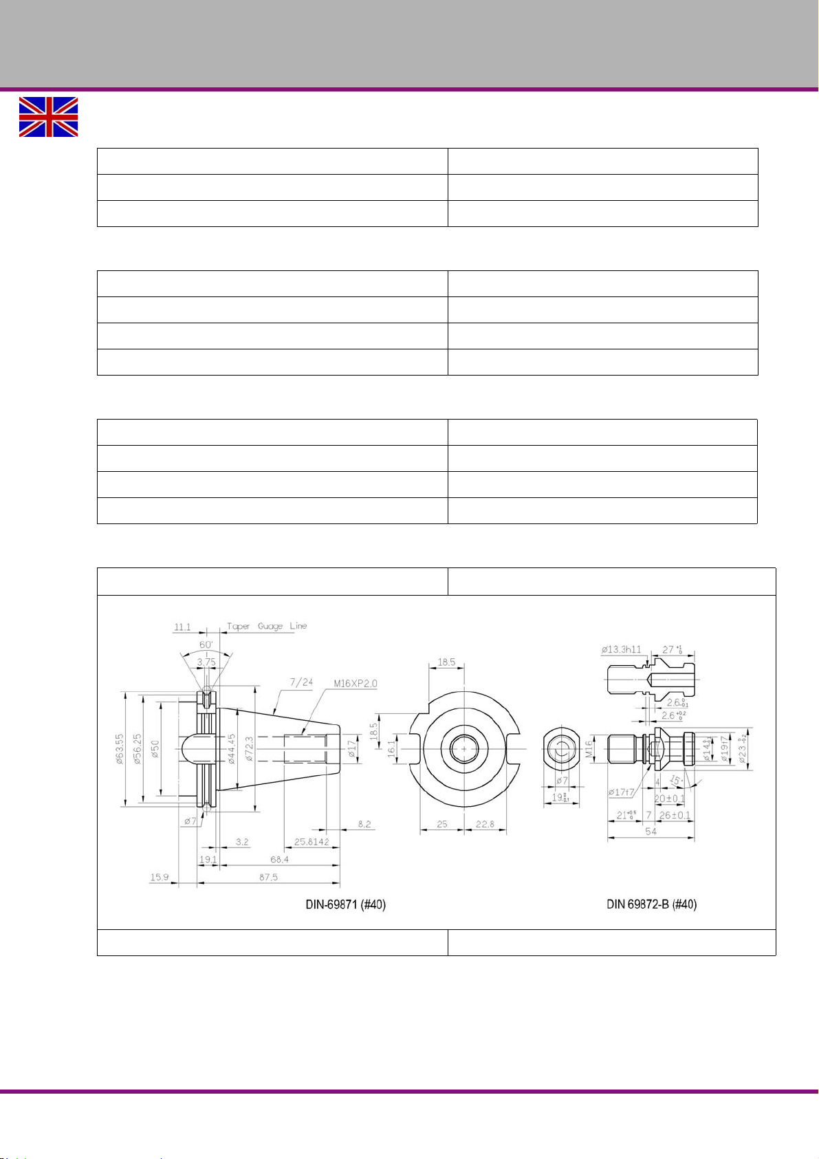
2.10.1 Standard milling spindle head
Spindle seat
Speed range [ min
Technical data
Version 1.1.6 dated 2014-10-16 Page 23Original operating instructions
-1
] 10 -10000
F150 GB
Page 24
OPTIMUM
MASCHINEN - GERMANY
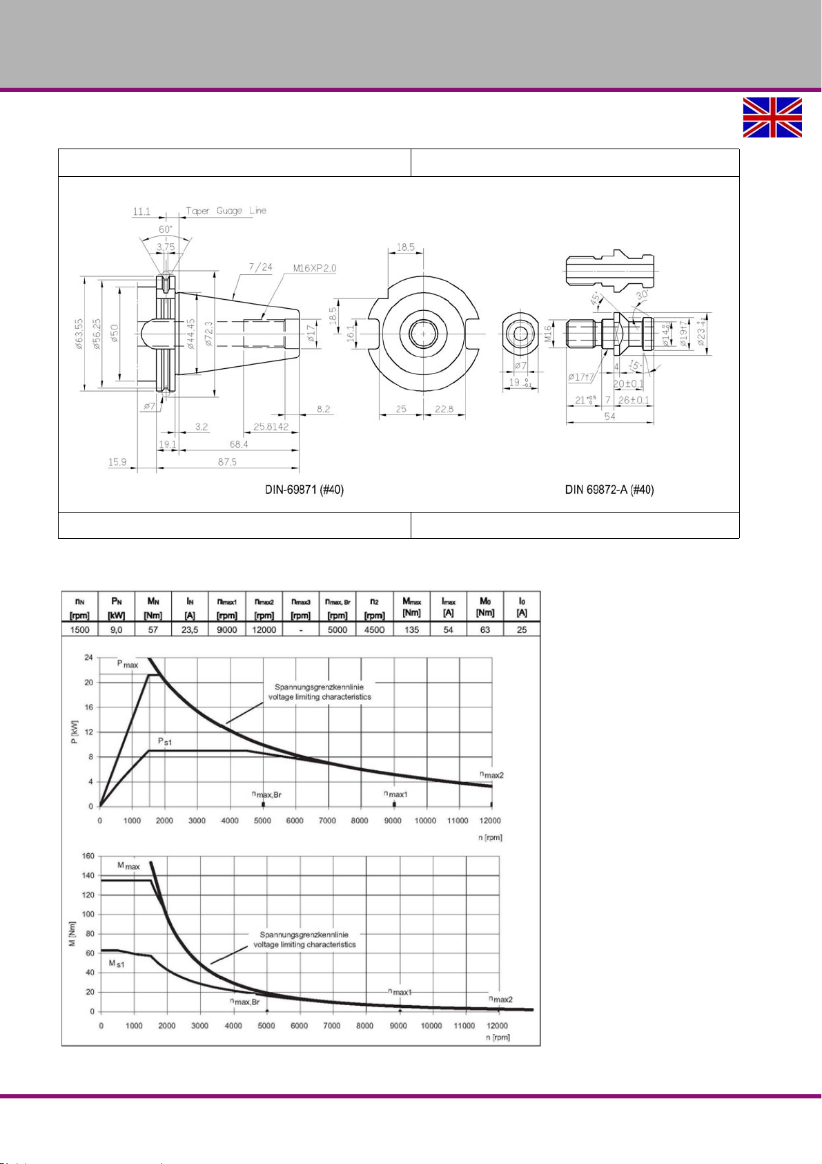
2.10.2 milling spindle head with use of a CTS system
Spindle seat
Speed range [ min
2.11 Spindle capacity
-1
] 10 -10000
F150GB
Version 1.1.6 dated 2014-10-16Page 24 Original operating instructions
Technical data
Page 25
2.12 Environmental conditions- operation
Temperature 19 - 21 °C (for an optimum milling result)
Admissible relative humidity 5...80 % no condensation
Compressed air 700...1060 hPa
2.13 Environmental conditions - storage
Temperature 5 - 45 °C
2.14 Optional coolant delivery through the spindle
CTS - C oolant T hroug S pindle
Integrated unit External unit External unit
Item no. 351121008 351121009 351121003
Pump pressure 20 bar 20 bar 70 bar
OPTIMUM
MASCHINEN - GERMANY
19 - 21 °C (for operation without malfunc-
tions)
Outlet filter 40μm25μm25μm
Pre filter pump 150μm40μm40μm
Tank capacity [ liter ] - 165
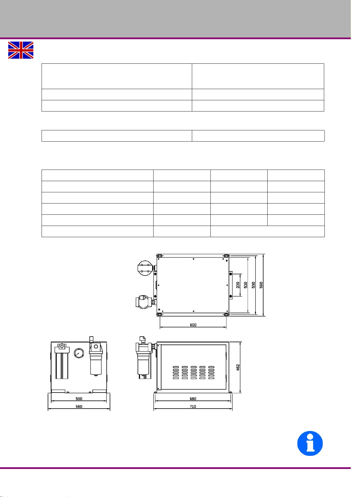
2.14.1 Dimensions integrated unit 20 bar
Img.2-1: 351121008
INFORMATION
The integrated CTS unit is supplied with coolant from the coolant tank of the machine.
Technical data
Version 1.1.6 dated 2014-10-16 Page 25Original operating instructions
F150 GB
Page 26
OPTIMUM
MASCHINEN - GERMANY
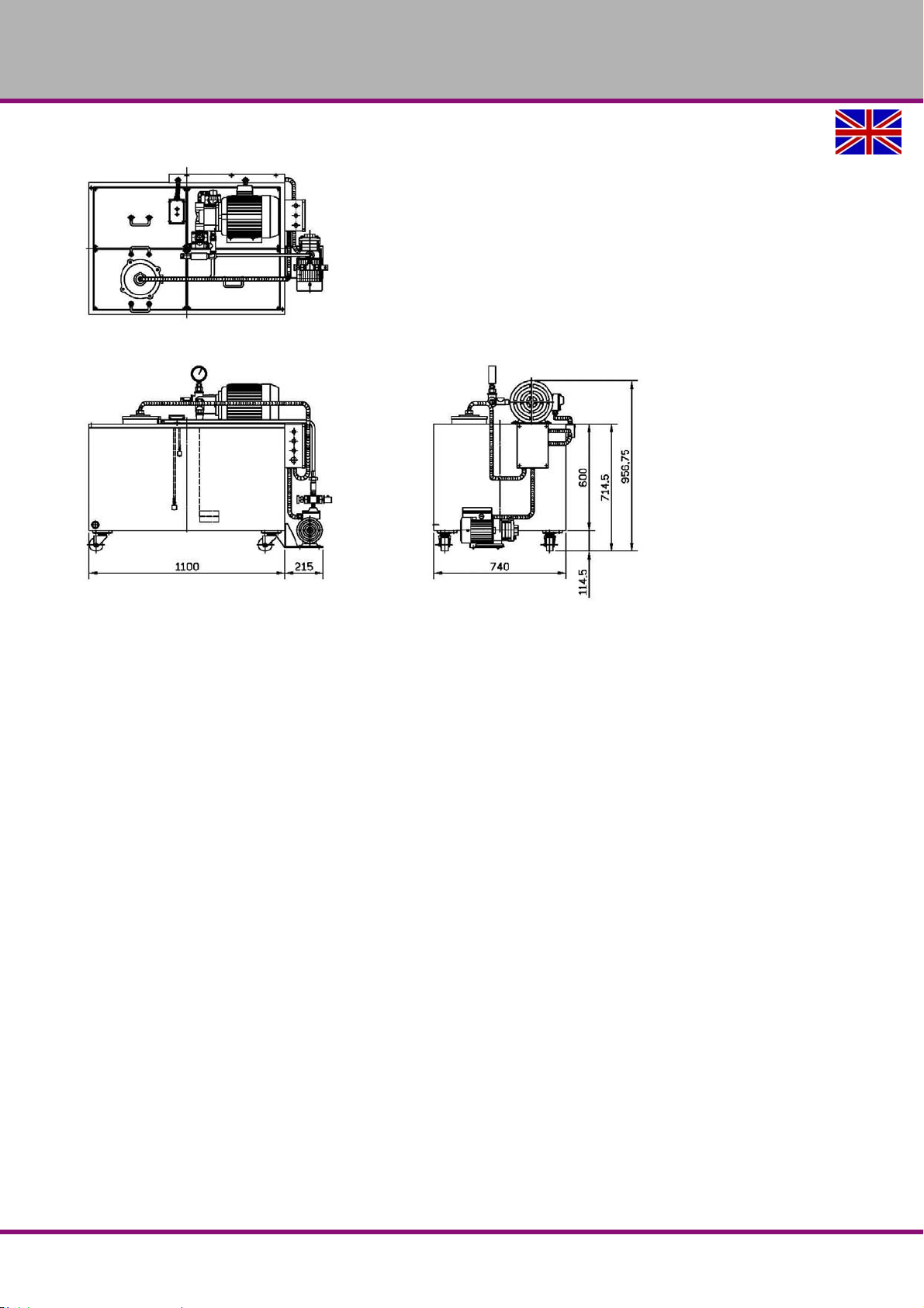
2.14.2 Dimensions external unit 20 bar and 70 bar
Img.2-2: 351121009 and 351121003
F150GB
Version 1.1.6 dated 2014-10-16Page 26 Original operating instructions
Technical data
Page 27
OPTIMUM
MASCHINEN - GERMANY
2.15 Emissions
The emission of the CNC machine is below 80 dB(A).
If the CNC machine is installed in an area where various machines are in operation, the noise
exposure (immission) on the operator of the CNC machine at the working place may exceed
80dB(A).
INFORMATION
This numerical value was measured on a new machine under proper operating conditions.
Depending on the age respectively on the wear of the machine it is possible that the noise
behaviour of the machine changes.
Furthermore, the factor of the noise emission is also depending on manufacturing influencing
factors, e.g. speed, material and clamping conditions.
INFORMATION
The specified numerical value is the emission level and not necessarily a safe working level.
Though there is a dependency between the degree of the noise emission and the degree of the
noise disturbance it is not possible to use it reliably to determine if further precaution measures
are required or not.
The following factors influence the actual degree of the noise exposure of the operator:
Characteristics of the working area, e.g. size or damping behaviour,
other noise sources, e.g. the number of machines,
other processes taking place in proximity and the period of time during which the operator is
exposed to the noise.
Furthermore, it is possible that the admissible exposure level might be different from country to
country due to national regulations.
This information about the noise emission should, however, allow the operator of the machine
to more easily evaluate the hazards and risks.
CAUTION!
Depending on the overall noise exposure and the basic threshold values the machine
operators must wear appropriate hearing protection.
We generally recommend to use a noise protection and a hearing protection.
2.16 Tools and tool holding fixtures
CAUTION !
When using tools with larger diameters or at higher speeds!
The balancing of the tools has to amount to
0 - 6000 min
from a speed of 6000 min
according to DIN / ISO 1940.
-1
- G 6,3
-1
- G 2,5
Technical data
Version 1.1.6 dated 2014-10-16 Page 27Original operating instructions
F150 GB
Page 28
OPTIMUM
MASCHINEN - GERMANY
3 Assembly and commissioning
INFORMATION
The CNC machine is pre assembled. It is delivered in a transport box. After the unpacking and
the transportation to the installation site it is necessary to mount and assemble the individual
components of the CNC-machine.
3.1 Dimensions of the packing
Length Width Height
Packaging F150 2540 2250 2380
3.2 Scope of delivery
Compare the delivery volume with the delivery note.
Check the status of theCNC machinesaw immediately upon receipt and claim possible damages at the last carrier also if the packing is not being damaged. In order to ensure claims
towards the freight carrier we recommend you to leave the machines, devices and packing
material for the time being in the status at which you have determined the damage or to take
photos of this status. We would like to ask you to inform us about any other claims within six
days upon receipt of the delivery.
Check if all parts are firmly seated.
3.3 Transport
WARNING!
Severe or fatal injuries may occur if the machine or parts of the machine tumble or fall
down from the forklift truck or from the transport vehicle. Follow the instructions and
information on the transport crate.
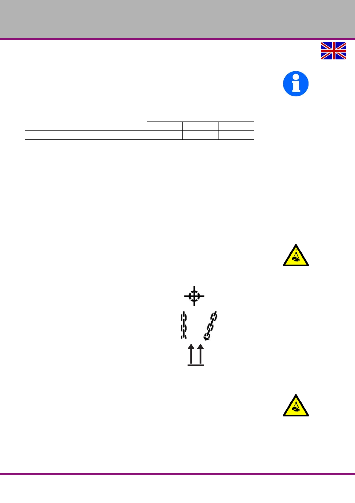
Centres of gravity
Load suspension points (Marking of the top sur-
face - arrows pointing to the top)
Prescribed transportation position (Marking of the
top surface)
Means of transport to be used
Weights
WARNING!
The use of unstable lifting and load suspension equipment that might break under load
can cause severe injuries or even death.
Check that the lifting and load suspension gear has sufficient load capacity and that it is
in perfect condition.
Observe the accident prevention regulations.
Fasten the loads properly.
Never walk under suspended loads!
F150GB
Assembly and commissioning
Version 1.1.6 dated 2014-10-16Page 28 Original operating instructions
Page 29
OPTIMUM
MASCHINEN - GERMANY
3.4 Storage
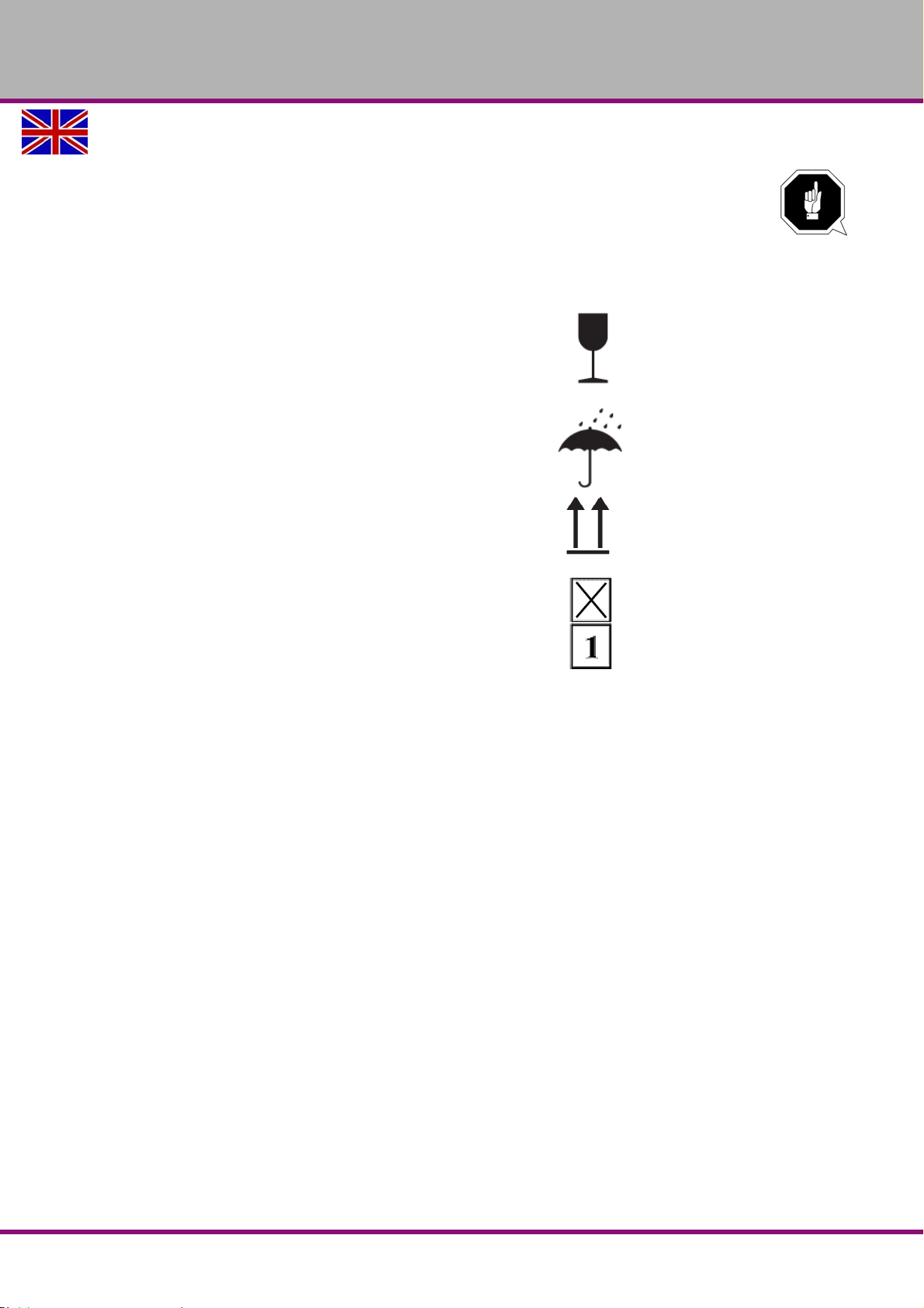
ATTENTION!
In case of wrong and improper storage, electrical and mechanical machine components
might get damaged and destroyed.
Store packed and unpacked parts only under the intended environmenta l conditions.
Follow the instructions and information on the transport crate.
Fragile goods
(Goods require careful handling)
Protect against moisture and humid environment
Prescribed position of the packing case (Marking
the top surface - arrows pointing to the top)
Maximum stacking height
Example: not stackable - do not stack a second
packing case on top of the first packaging case
Consult Optimum Maschinen Germany GmbH if the CNC machine and accessories are stored
for more than three months or are stored under different environmental conditions than those
specified here.
"Environmental conditions - storage“ on page 25
Assembly and commissioning
Version 1.1.6 dated 2014-10-16 Page 29Original operating instructions
F150 GB
Page 30
OPTIMUM
MASCHINEN - GERMANY
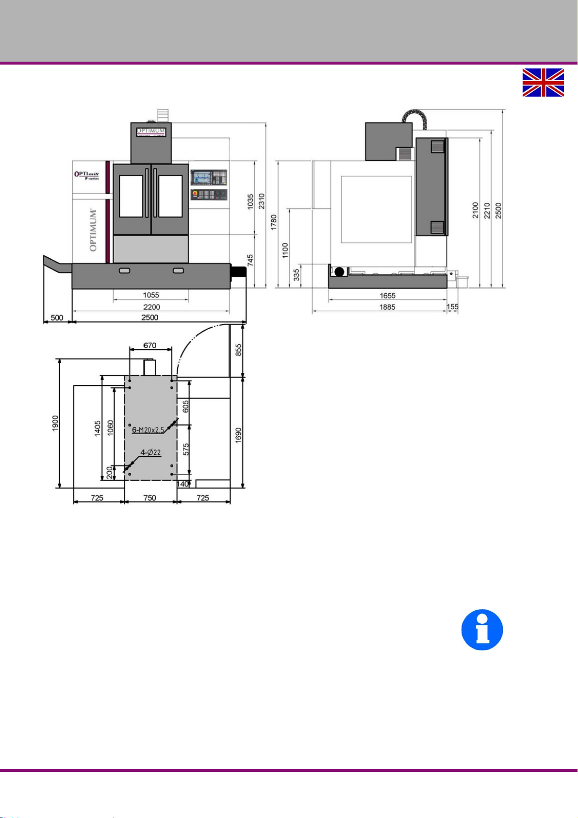
3.5 Installation plan F150
Img.3-1: Installation plan
3.6 Requirements regarding the installation site
Organize the working area around the CNC machine according to the local safety regulations.
The working area for operating, maintenance and repair must not be hindered. Follow the prescribed safety areas and escape routes according to VDE 0100 part 729 as well as the environmental conditions for the operation of the CNC machine.
INFORMATION
The mains plug of the CNC machine must be freely accessible.
F150GB
Assembly and commissioning
Version 1.1.6 dated 2014-10-16Page 30 Original operating instructions
Page 31
OPTIMUM
MASCHINEN - GERMANY
3.7 Transportation to the installation site
ATTENTION!
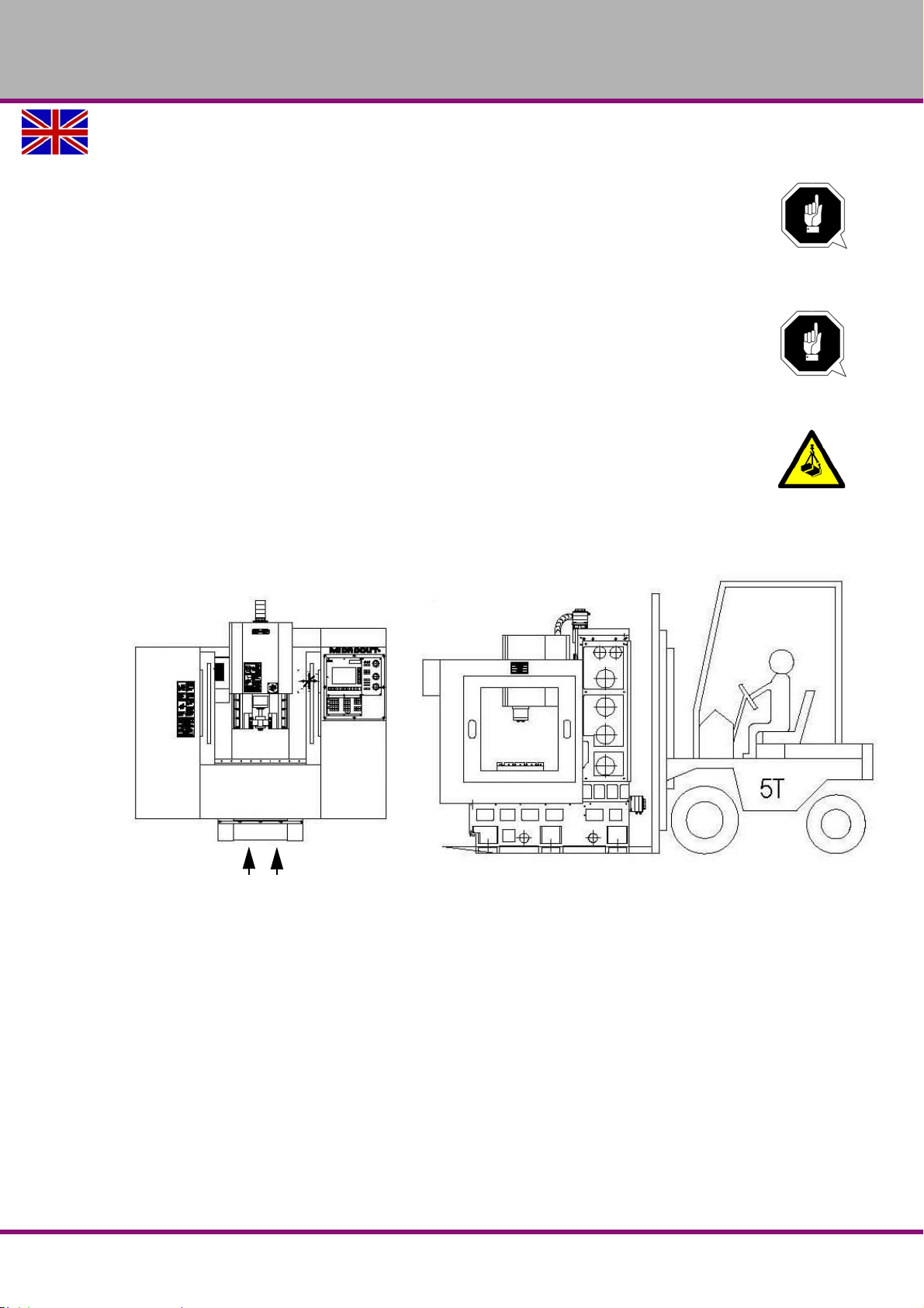
The CNC machine is lifted and transported at the machine substructure or at the load
suspension points using an appropriate conveyor system.
Check the substructure. The substructure has to bear the load. "Load capacity of the
substructure [kN/m2]“ on page 21
ATTENTION!
Make sure that the load attachment point is balanced (Centre of gravity).
Disassemble the clamping bolts which are used to fix the machine on the pallet.
Lift the CNC machine carefully from the pallet of the transportation box by means of a crane
or a fork-lift truck.
WARNING!
The use of unstable lifting and load suspension equipment that might break under load
can cause severe injuries or even death.
3.7.1 Forklift truck
Img.3-2: Transporting by fork-lift truck
Assembly and commissioning
Version 1.1.6 dated 2014-10-16 Page 31Original operating instructions
F150 GB
Page 32
OPTIMUM
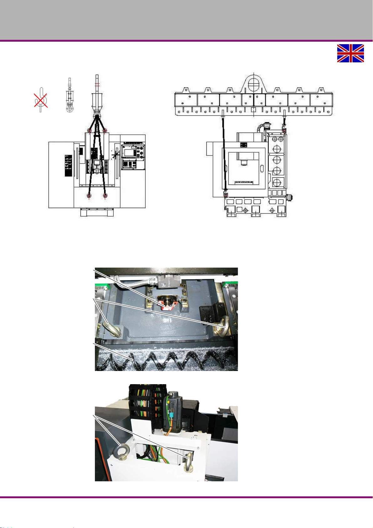
Transport device 3511201
Transportation lock
Eye bolts M24
Chip conveyor
Eye bolts M24
MASCHINEN - GERMANY
3.7.2 Crane
Img.3-3: Transporting by crane
If not yet available you must mount four ring bolts at the provided load application points on the
machine substructure and on the column.
Attach the transport device, item no. 3511201 on the crane.
Img.3-4: Load suspension point machine substructure
F150GB
Img.3-5: Load suspension point (column)
Assembly and commissioning
Version 1.1.6 dated 2014-10-16Page 32 Original operating instructions
Page 33
OPTIMUM
Adjusting screw
Counter nut
Machine foot
MASCHINEN - GERMANY
Fix the load suspension gear (e.g. lifting slings) on the four ring bolts of the machine sub-
structure and of the column.
WARNING!
There must be no inclined traction due to the load suspension gear.
Img.3-3: “Transporting by crane“ on page 32
3.8 Installation and assembly
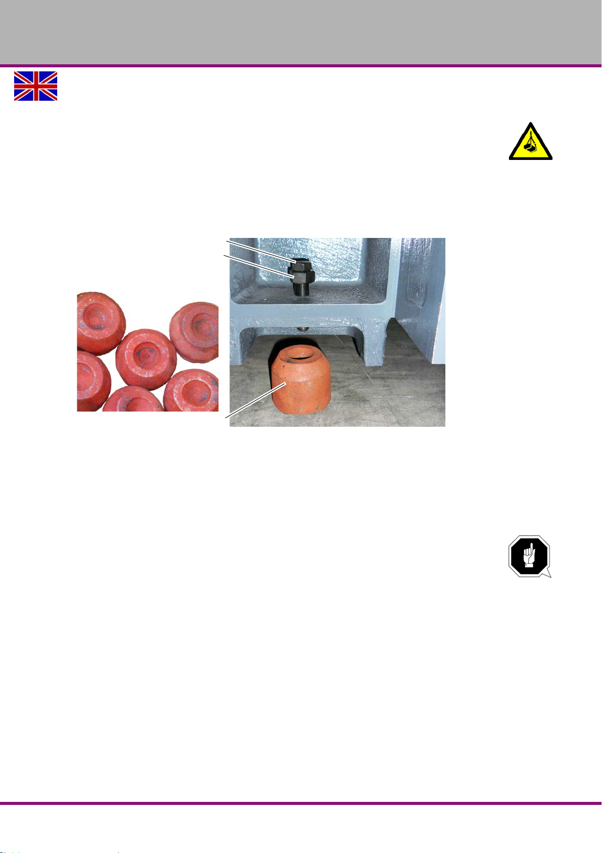
Position the machine feet included in the delivery volume below the adjusting screws of the
machine substructure.
Align the CNC machine with a machine spirit level.
"Total weight [kg]“ on page 21.
Img.3-6: Machine feet
3.8.1 Aligning the machine
Align the CNC machine on the machine bed by means of a machine spirit level. Use the set
screws in order to perform the required height levelling.
The slope deviation of all levels must not exceed 0.03/1000mm.
ATTENTION!
An insufficient rigidity of the substructure leads to superposition of vibrations between
the multifunctional CNC machine and the substructure (natural frequency of the
components). Critical speeds and moves in the axis with displeasing vibrations are
rapidly achieved in case of insufficient rigidity of the whole system and will lead to bad
milling results.
Check the correct alignment of the machine after a few days of usage.
Fix by means of adjusting screws.
Assembly and commissioning
Version 1.1.6 dated 2014-10-16 Page 33Original operating instructions
F150 GB
Page 34
OPTIMUM
the coolant / lubricant tank
with chip conveyor
Chip conveyor
Cover plate
Chip tube
MASCHINEN - GERMANY
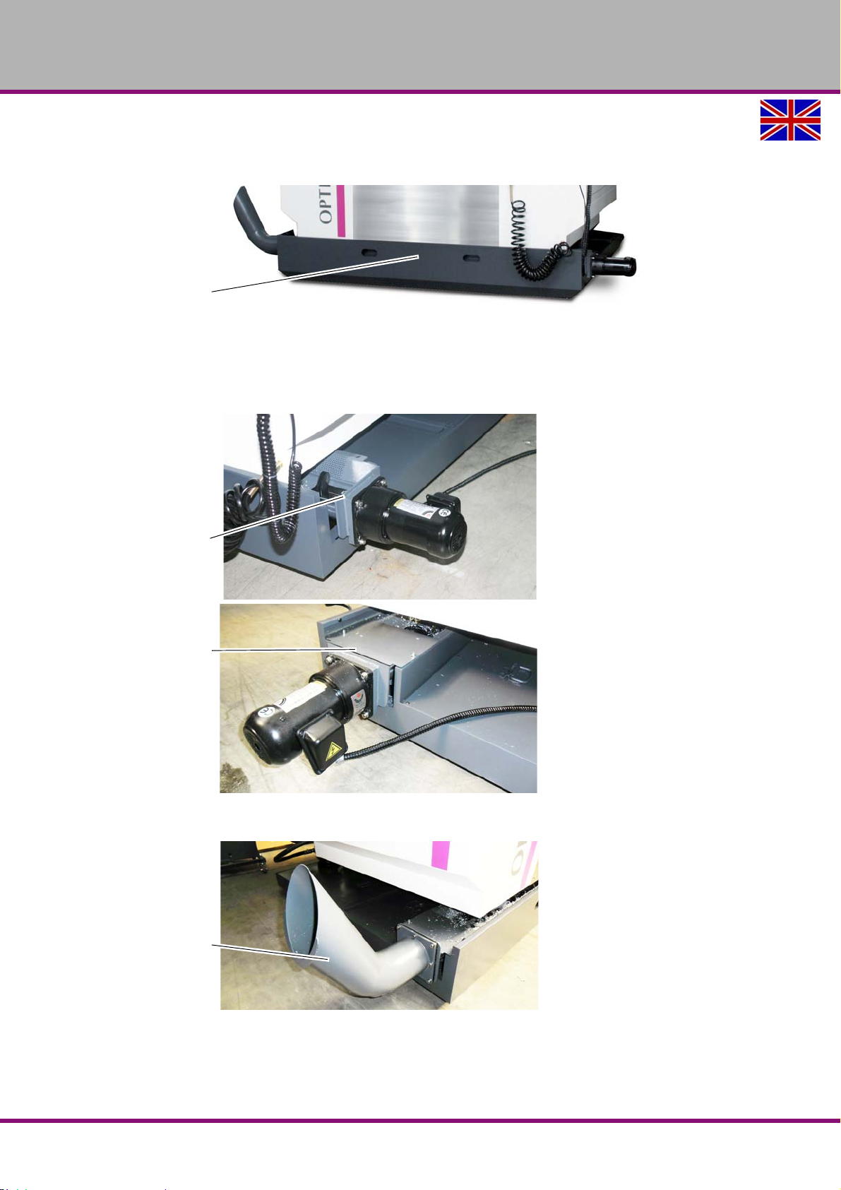
3.8.2 Assembly of the coolant / lubricant tank and of the chip conveyor
Push the coolant / lubricant tank below the CNC machine.
Img.3-7: Mounting the coolant / lubricant tank
Make sure that the coolant / lubricant tank is correctly aligned underneath the CNC
machine.
Mount the chip conveyor incl. cover plate.
F150GB
Img.3-8: Chip conveyor with drive motor
Img.3-9: Chip conveyor
"Späneförderer - Chip convejor“ on page 135
Assembly and commissioning
Version 1.1.6 dated 2014-10-16Page 34 Original operating instructions
Page 35
OPTIMUM
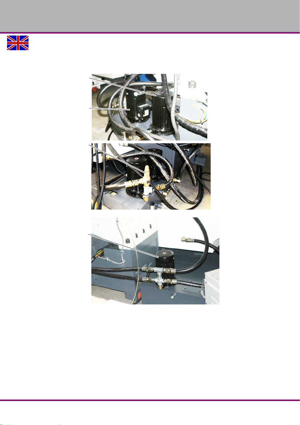
Pump spindle cooling
Img.3-13: “Spindle cooling“
on page 36
Pump cleaning gun
Img.3-15: “Cleaning gun“
on page 37
Pressure reduction valve
Pump cleaning gun
Pump chip flushing
Img.3-14: “Chip flushing“ on
page 36
MASCHINEN - GERMANY
3.8.3 Assembly of the coolant / lubricant pumps
Position the three coolant / lubricant pumps in the corresponding seat of the coolant / lubri-
cant tray. Screw down the coolant / lubricant pumps on the coolant / lubricant tray.
Img.3-10: Coolant / lubricant pumps
Img.3-11: Coolant / lubricant pumps
Assembly and commissioning
Version 1.1.6 dated 2014-10-16 Page 35Original operating instructions
F150 GB
Page 36
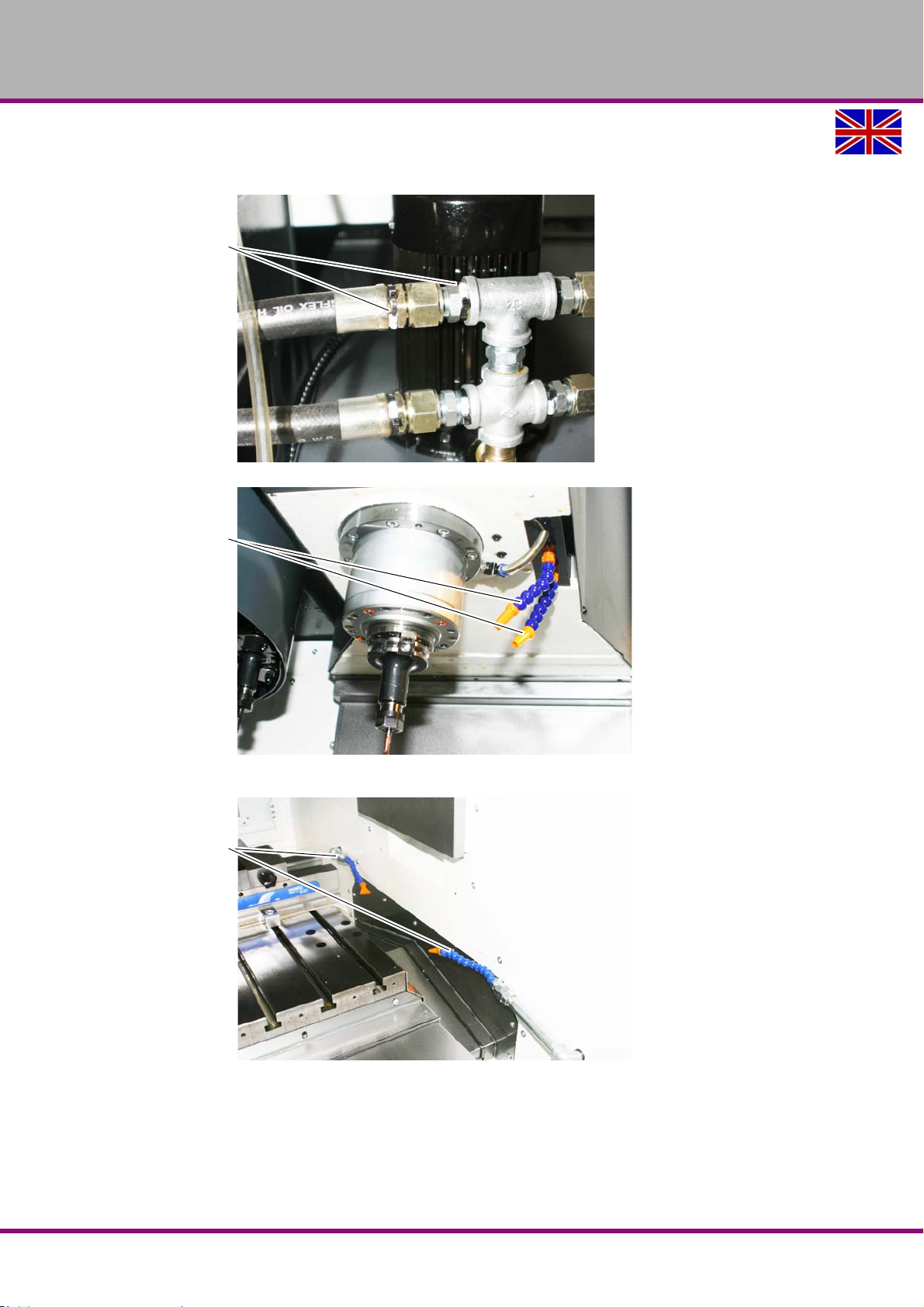
OPTIMUM
Designation coolant / lubri-
cant hoses
Spindle cooling
Chip flushing
MASCHINEN - GERMANY
Mount the coolant / lubricant hoses of the cooling lubricant equipment. The connections of
the coolant / lubricant hoses have a designation, parts with the same designation belong
together.
Img.3-12: Coolant lubricant hoses
Img.3-13: Spindle cooling
Img.3-14: Chip flushing
F150GB
Assembly and commissioning
Version 1.1.6 dated 2014-10-16Page 36 Original operating instructions
Page 37
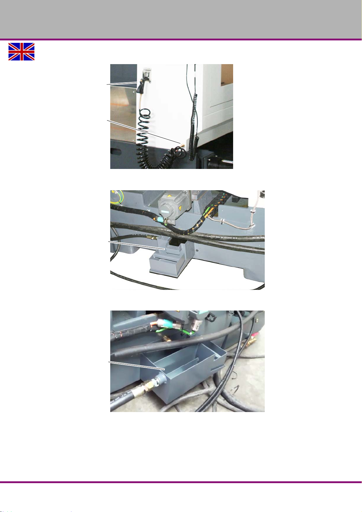
Mount the spiral hose incl. the cleaning gun.
Cleaning gun
Connection
Cleaning gun
Oil separator
type 1
Oil separator
type 2
Img.3-15: Cleaning gun
Mount the oil separator of the coolant / lubricant tank.
OPTIMUM
MASCHINEN - GERMANY
Img.3-16: Oil separator of the coolant / lubricant tank type 1
Img.3-17: Oil separator of the coolant / lubricant tank type 2
Assembly and commissioning
Version 1.1.6 dated 2014-10-16 Page 37Original operating instructions
F150 GB
Page 38
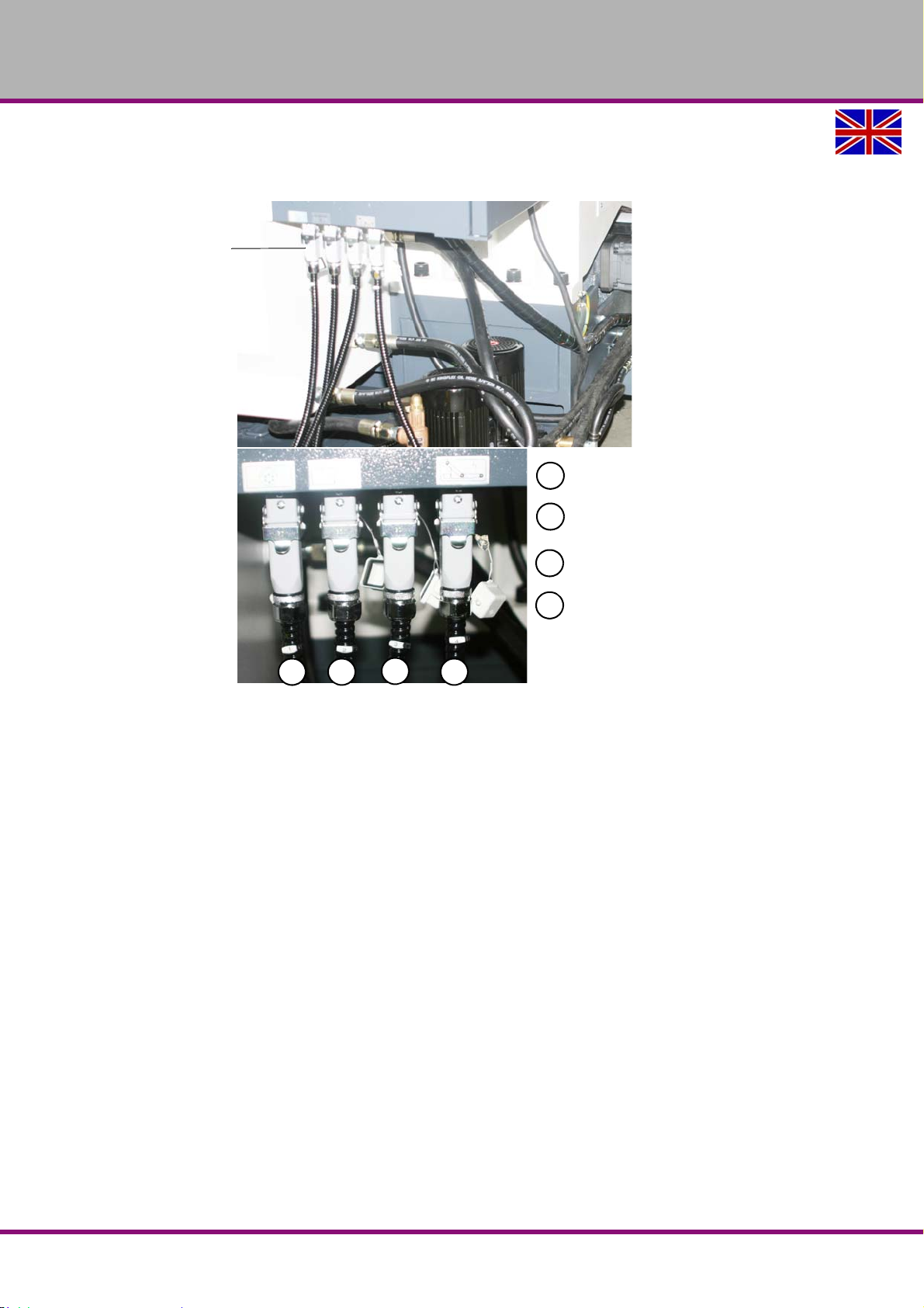
OPTIMUM
Connector plug
1 2
3
4
1
2
3
4
Spindle cooling
Cleaning gun
Chip flushing
Chip conveyor
MASCHINEN - GERMANY
Connect the connector plugs of the coolant / lubricant pumps and of the chip conveyor, as
well as the coolant / lubricant hoses of the coolant / lubricant tank. Make sure that the plug
connections are correctly connected.
Img.3-18: Connector plug
F150GB
Assembly and commissioning
Version 1.1.6 dated 2014-10-16Page 38 Original operating instructions
Page 39
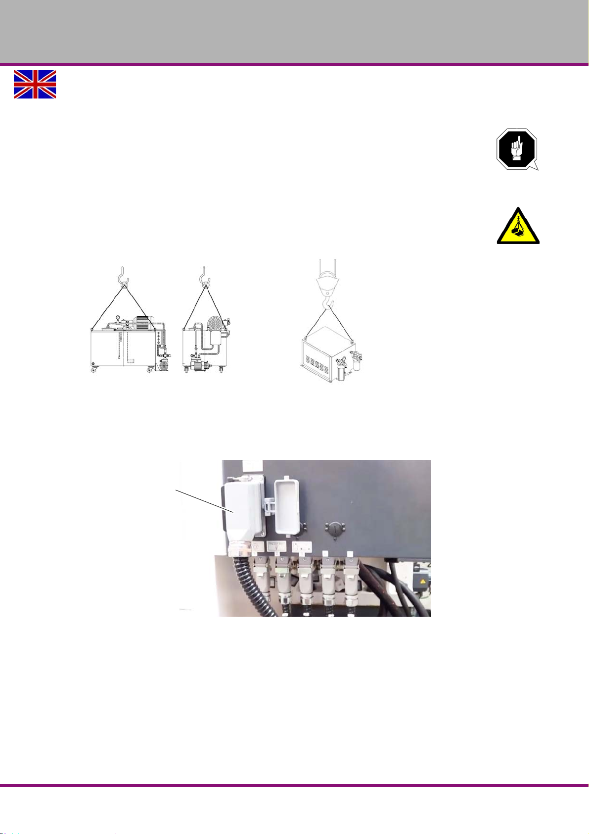
OPTIMUM
Connector plug
MASCHINEN - GERMANY
3.8.4 Mounting the optional coolant through spindle
CTS - Coolant Through Spindle
ATTENTION!
CTS the external system can be used only with a specific mixing ratio of the refrigeration
lubricant. Use only a mixing ratio
oil / water of 1/4
The CTS unit can be placed anywhere on the floor.
CAUTION!
Make sure for a balanced load stop, especially if coolant is still in the external unit.
Transport CTS unit
Img.3-19: external unit internal unit
Connect the connector of the external cooling unit.
Check if the pump motor is turning in the correct rotation direction.
Mount the coolant hoses. The connections of the coolant / lubricant hoses have a designa-
tion, parts with the same designation belong together.
Img.3-20: Connecting plug CTS unit
Assembly and commissioning
Version 1.1.6 dated 2014-10-16 Page 39Original operating instructions
F150 GB
Page 40
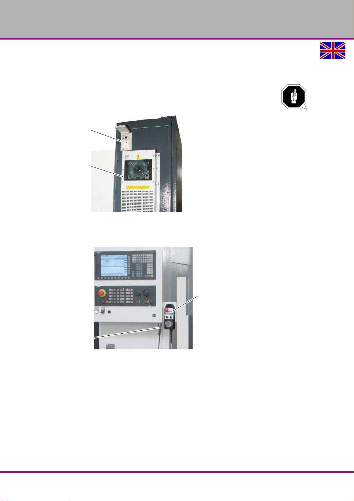
OPTIMUM
RJ45 connection
USB connection
230V connection
Heat exchanger
Connector plug
Hand wheel
MASCHINEN - GERMANY
3.8.5 Mounting the heat exchanger on the switch cabinet
Mount the heat exchanger onto the switch cabinet - if it had been disassembled since it is
transported. Connect the heat exchanger into the switch cabinet to ~230V.
ATTENTION!
This work must only be performed by an electrical specialist. The guarantee will become
null and void if the machine is wrongly connected!
Img.3-21: Heat exchanger on the switch cabinet
3.8.6 Mounting the electronic handwheel
Mount the connection cable of the handwheel on the operating panel of the CNC machine
Img.3-22: Electronic handwheel
F150GB
Assembly and commissioning
Version 1.1.6 dated 2014-10-16Page 40 Original operating instructions
Page 41
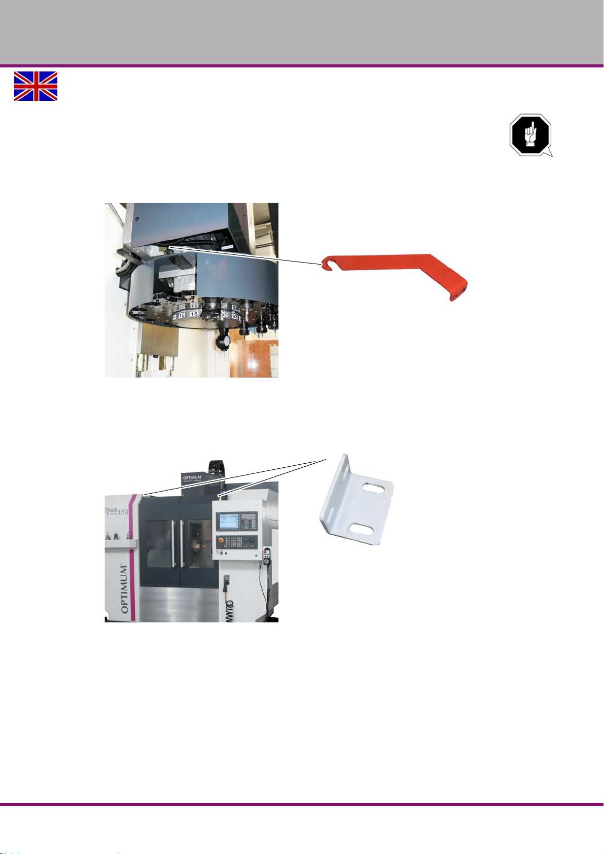
OPTIMUM
MASCHINEN - GERMANY
3.9 Transport locking devices
ATTENTION!
The machine is equipped with transport locks. Before performing the electrical
connection it is necessary to remove the transport locks.
The transport locking devices are positioned on the axis, doors and tool changer.
3.9.1 Transport locking device, 16-type tool changer
Img.3-23: Transport locking tool changer.
3.9.2 Transport locking device, doors
Remove the transport lockings from the doors.
Img.3-24: Transport locking door
Assembly and commissioning
Version 1.1.6 dated 2014-10-16 Page 41Original operating instructions
F150 GB
Page 42
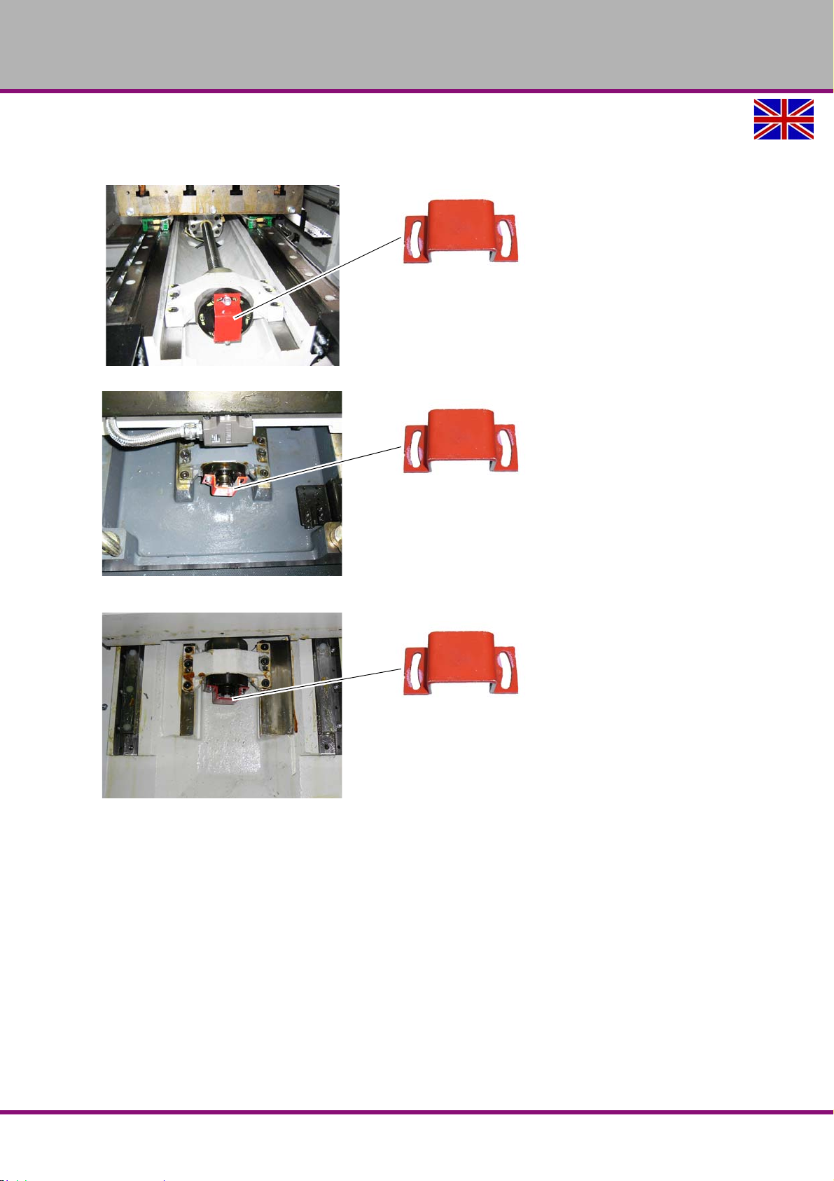
OPTIMUM
MASCHINEN - GERMANY
3.9.3 Transport locking device, axes
Remove the transport lockings on the 3 axes X Y Z.
Img.3-25: Transport lock X-axis
Img.3-26: Transport lock Z-axis
Img.3-27: Transport lock Y-axis
F150GB
Assembly and commissioning
Version 1.1.6 dated 2014-10-16Page 42 Original operating instructions
Page 43
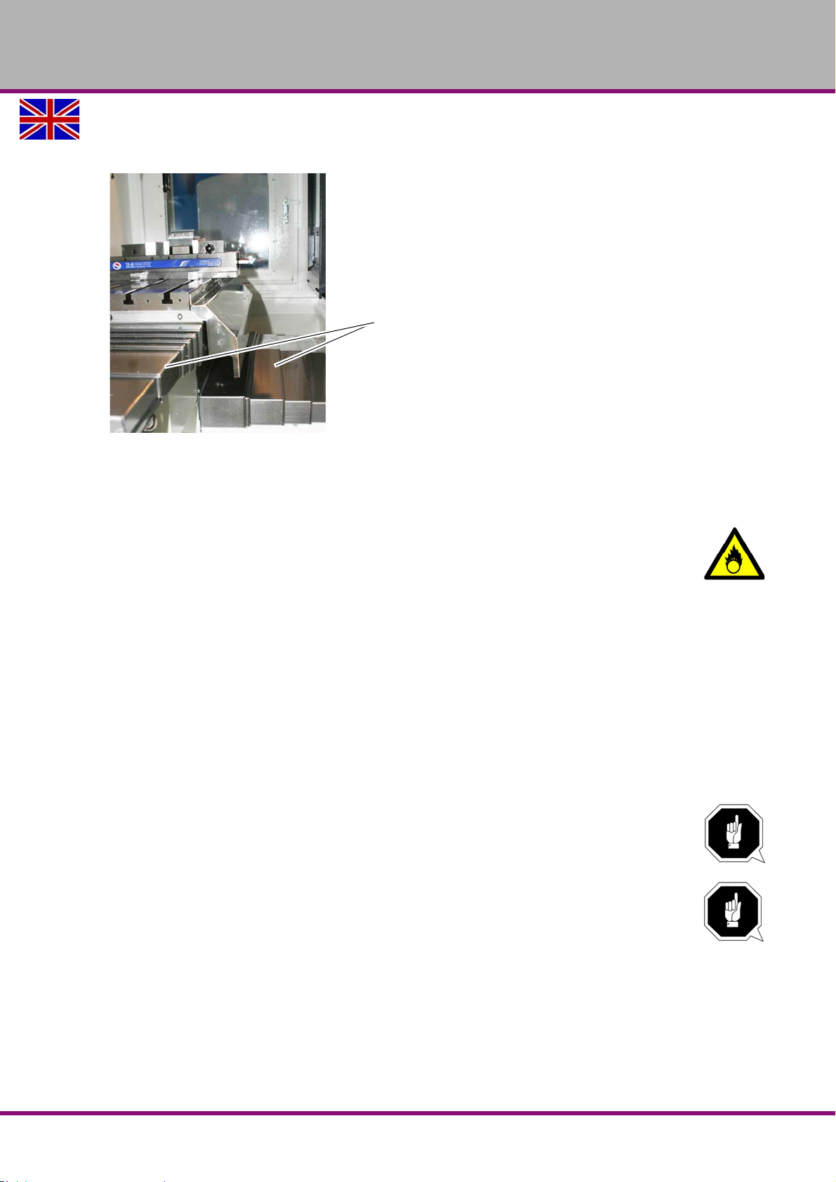
3.9.4 Mounting the telescopic covers
Telescopic covers
Mount the telescopic covers on the axis.
Img.3-28: Telescopic covers milling table
"Frästisch - Milling table 2- 2“ on page 127
OPTIMUM
MASCHINEN - GERMANY
3.9.5 Corrosion protection
WARNING!
Observe the corresponding safety data sheet of your supplier when using
methylbenzene
A corrosion protection is applied on the machine table and on the guiding surfaces for transport
and storage. Remove the anti-corrosive agent from the CNC machine before first commissioning. To do so, use hard coal oil or methylbenzene, EU identification number 601-021-00-3 ,
CAS number 108-88-3. Have the medium react for about 15 minutes. The anticorrosive agent
soaks and then it may be easily removed.
Methylbenzene, also called toluene, is a colourless, typically smelling volatile liquid which is
similar to benzene in many respects. Toluene is an aromatic hydrocarbon, it often replaces the
toxic benzene as solvent. Among others it is also included in petrol.
3.9.6 Electrical connection
ATTENTION!
Observe the rotating field!
"Warming up the machine“ on page 48
The guarantee will become null and void if the machine is wrongly connected!
ATTENTION!
This work must only be performed by an electrical specialist. The guarantee will become
null and void if the machine is wrongly connected!
"Qualification of personnel“ on page 11
Firmly connect the CNC machine to the terminal box. It is not allowed to connect the machine
using a standard 32 A CEE plug, since the stray current of the frequency converter is exceeding the admissible value of 3.5mA (refer to EN 50178 / VDE 5.2.11.1).
Assembly and commissioning
Version 1.1.6 dated 2014-10-16 Page 43Original operating instructions
F150 GB
Page 44

OPTIMUM
FI protected switch sensitive for pulse current
Type A
F protected switch sensitive to AC/DC
Type B
300 mA
300 mA
MASCHINEN - GERMANY
ATTENTION!
Under extreme circumstances and depending on the quality of the network it may lead to
interferences caused by the machine. If necessary and in order to exclude retroactive
effects on the internal power supply system, the operator should install a line filter on
the machine. Therefore, at working places where lots of powerful consumers are
connected it might also be necessary to use a system for network compensation. Please
also request your electricity supplier for this purpose.
ATTENTION!
Frequency converter (drive regulator) might release the Fl protected switch of your
electrical supply. In order to avoid malfunction, you either need an Fl protected switch
sensitive for pulse current or AC/DC sensitive.
In case of malfunction or release of the FI protected switch, please check the installed type.
The following signs indicate if your machine is equipped with one of the FI protected switches
described above.
Img.3-29: Symbols FI protected switch
We recommend you to use an FI protected switch sensitive to AC/DC. FI protected switches
sensitive to AC/DC (RCCB, type B are adequate for 1-phase and 3-phase fed frequency converters (driving regulator).
An FI protected switch type AC (only for alternating current) is not appropriate for frequency
converters. FI protected switches type AC are no longer used.
F150GB
Assembly and commissioning
Version 1.1.6 dated 2014-10-16Page 44 Original operating instructions
Page 45
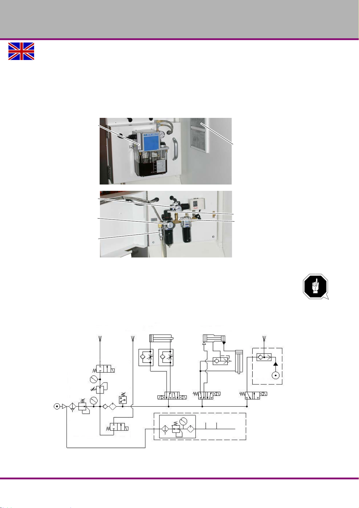
OPTIMUM
Compressed air diagram
Central lubrication unit
Manometer
Air purge
Air pressure gauge con-
nection
Compressed air supply
Adjusting screw
Maintenance unit
Tool clamp / unclamp
Tool changer
forward / backward
Air blow
Air blow
CTS
Air purge
Option
CTS
X axis
Y axis
Z axis
Option sealed linear encoders
MASCHINEN - GERMANY
3.9.7 Connection compressed air supply
The compressed air maintenance unit is positioned behind the central lubrication unit.
Open the cover on which the central lubrication unit is located.
Connect the compressed air supply with at least 6.5 bars to the quick-action coupling of the
compressed air maintenance unit.
Adjust a pressure of 6.3 bars using the set screw of the maintenance unit.
ATTENTION!
In order to ensure a failure-free operation of the machine it is necessary that the required
air pressure is continuously applied on the machine at constant quality. In case of
insufficient air supply, for instance interruptions occur during tool change.
"Air consumption“ on page 21
Img.3-30: Compressed air maintenance unit
Assembly and commissioning
Version 1.1.6 dated 2014-10-16 Page 45Original operating instructions
F150 GB
Page 46
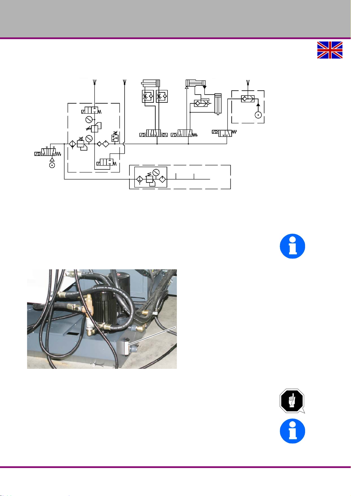
OPTIMUM
Tool clamp / unclamp
Tool changer
forward / backward
Air blow
Air blow
CTS
Air purge
Option
CTS
X axis
Y axis
Z axis
Option sealed linear encoders
Level indicator
MASCHINEN - GERMANY
Pneumatic diagram from year of construction 2014
3.10 First commissioning
3.10.1 Fill up coolant
INFORMATION
The CNC machine is delivered without cooling lubricant.
Fill the coolant / lubricant tank with an appropriate cooling lubricant via the machining room
CNC machine.
Img.3-31: Level indicator coolant / lubricant
"Cooling lubricants“ on page 93
ATTENTION!
Failure of the pumps in case of dry running. The pumps are lubricated by means of the
cooling lubricant. Do not start up the pumps without cooling lubricant.
INFORMATION
Use a water soluble environmentally compliant drilling emulsion as cooling lubricant
procured from the specialised trade.
Make sure that the cooling lubricant is properly absorbed.
F150GB
Assembly and commissioning
Version 1.1.6 dated 2014-10-16Page 46 Original operating instructions
Page 47
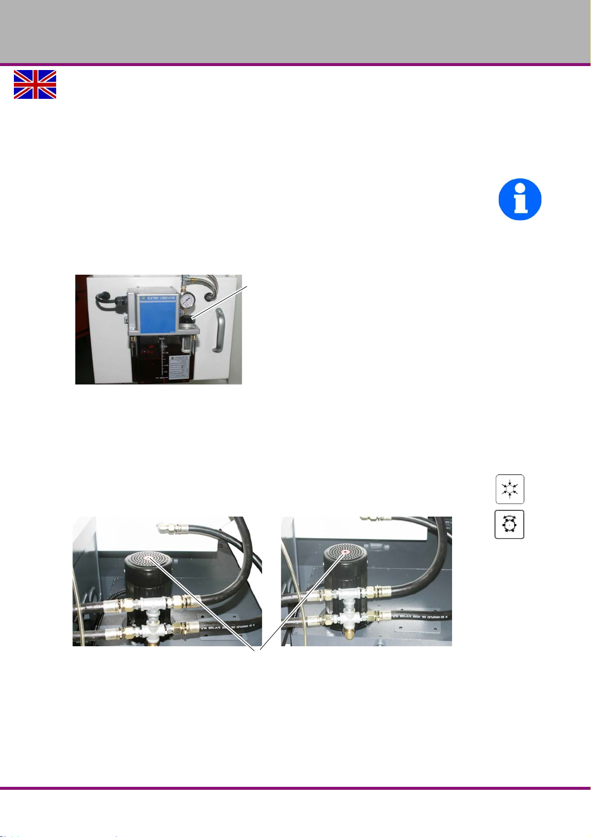
OPTIMUM
Filler hole
Arrow direction/direction of rotation
MASCHINEN - GERMANY
Respect the environment when disposing of any lubricants and coolants. Follow the
manufacturer’s disposal instructions.
"Cooling lubricants and tanks“ on page 108
3.11 Refill central lubrication system
The CNC machine is equipped with a central lubrication system.
INFORMATION
The CNC-milling machine is delivered without lubricating oil.
Fill the tank with lubricating oil via the filler hole.
"Cooling lubricants“ on page 93
"Adjusting the amount of oil at the central lubrication“ on page 116
Img.3-32: Central lubrication system
3.11.1 Functional test and controls
Check the direction of rotation of the CNC machine. There must be a right-handed rotating
field. If the direction of rotation is wrong, exchange two of the three phase conductors. At
this, the correct direction of rotation only refers to the drive of the cooling lubricant pumps.
Proceeding to set the direction of rotation:
Change over to the TSM mode "M8" or press the key.......
Observe the arrow direction resp. the direction of rotation of the cooling lubricant pump.
Img.3-33: Arrow direction/direction of rotation of the cooling lubricant pump
If the coolant / lubricant pump turns anticlockwise it is necessary to switch off the machine
and to have two of three phases (e.g. L1 and L2) exchanged by an electrical specialist!
Check all oil levels and filling levels of lubricants in the reservoirs.
Perform a safety test.
Assembly and commissioning
Version 1.1.6 dated 2014-10-16 Page 47Original operating instructions
F150 GB
Page 48
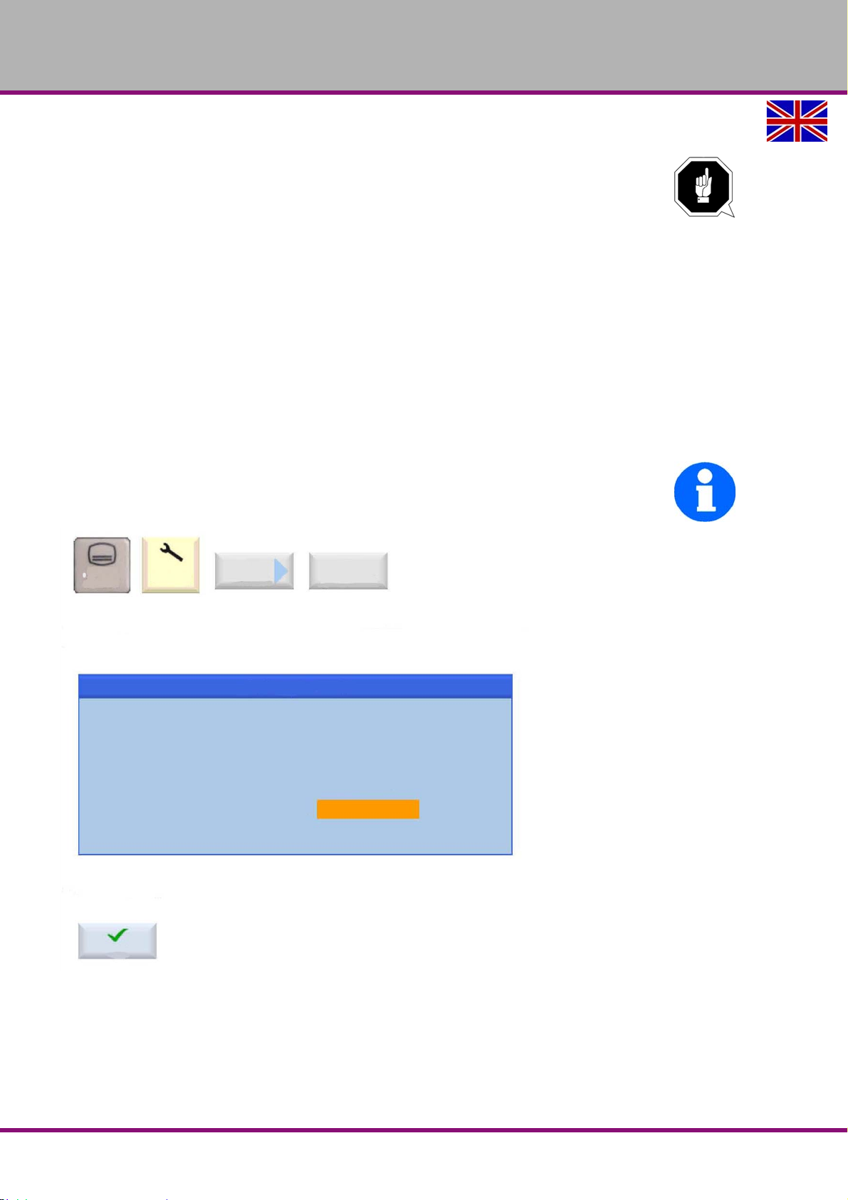
OPTIMUM
After typing the password it is confirmed by pressing the „OK“ soft key.
OK
Current access level:
Key switch 3
Please enter password:
Set password
A dialogue box is opened, this box shows the current access level and allows
a password to be entered using the keyboard.
MENU
SELECT
Setup
Password
Password
Change
MASCHINEN - GERMANY
3.11.2 Warming up the machine
ATTENTION!
If the CNC machine and in particular the milling spindle are immediately operated at
maximum load when cold, this may result in damages.
If the machine is cold, e.g. directly after having transported the machine, it should be
warmed up at a spindle speed of only 500 1/min for the first 30 minutes.
3.11.3 Passwords
Upon delivery the control SINUMERIK 828 D is protected with a password. In order to be able
to change parameters and data of the control it is necessary to enter a password.
switch“ on page 69
Press the following keys (refer to figure) to change the password.
Note down the passwords. In case of service these passwords are needed. In case of non
existing passwords during servicing the servicing has to be interrupted at cost of the operator.
Please also observe "access stage“ on page 69
INFORMATION
"Key
This illustration is an excerpt of the SINUMERIK 828D "Service documentation" of the company Siemens.
Img.3-34: Access stage
Please also refer to "Control technical protection“ on page 15 .
F150GB
Assembly and commissioning
Version 1.1.6 dated 2014-10-16Page 48 Original operating instructions
Page 49
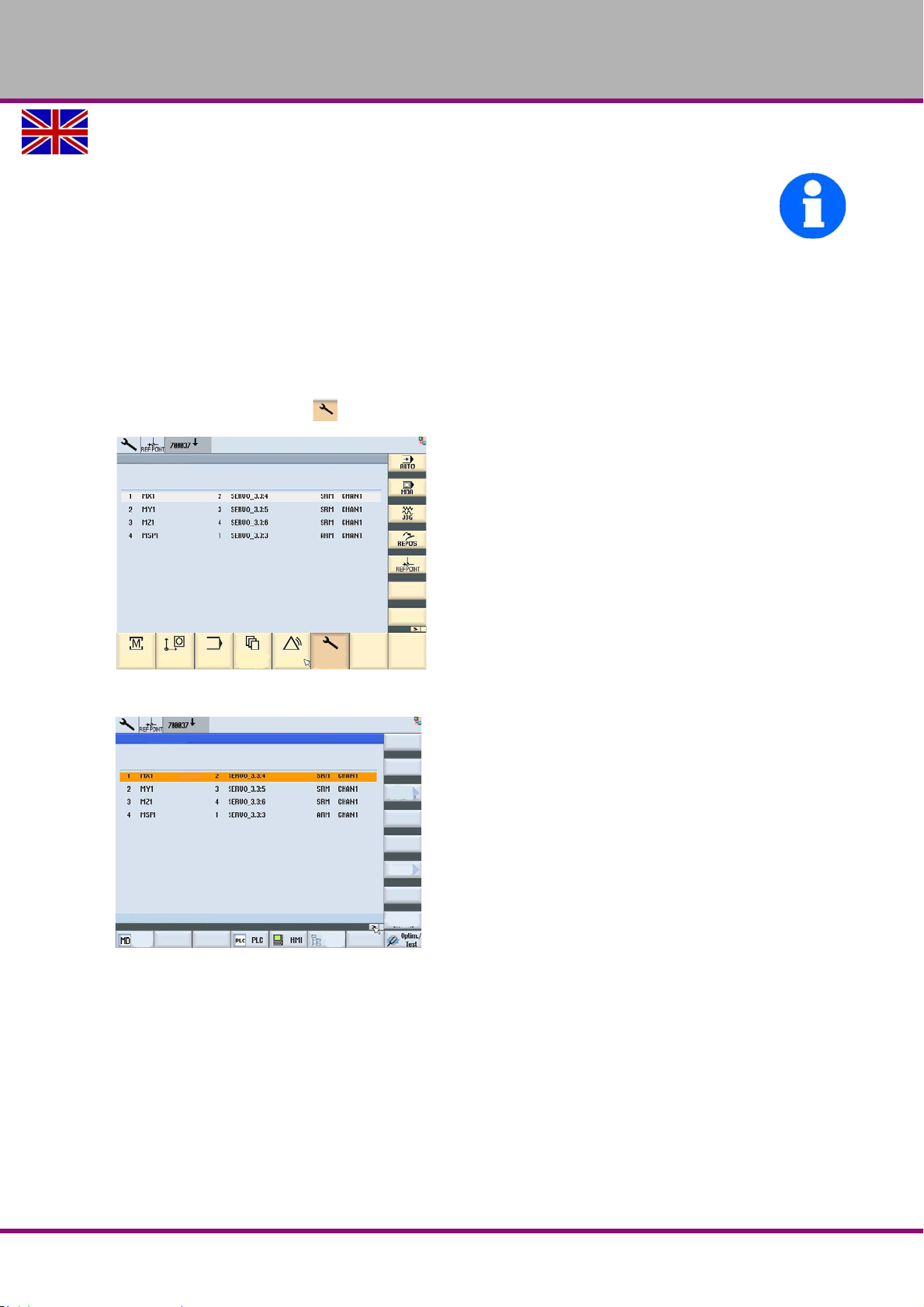
OPTIMUM
MASCHINEN - GERMANY
3.11.4 Data backup on the control
INFORMATION
The CNC control only provides a "transient working memory" for its internal machine programs
losing its contents at the latest after 3 weeks.
For this reason it is imperatively necessary to perform a data backup after commissioning the
machine respectively the machine control.
Furthermore, it is recommended to repeat this data backup in regular intervals.
Every eight hours the preset maintenance plan of the machines will remind you of performing a
data backup.
To perform the data backup please proceed as follows:
Press the button "Menu select".
Press the button "Start up ".
Img.3-35: Menu commissioning
Then select the menu item "data backup" and follow the instructions.
Img.3-36: Menu data backup
Assembly and commissioning
Version 1.1.6 dated 2014-10-16 Page 49Original operating instructions
F150 GB
Page 50

OPTIMUM
MASCHINEN - GERMANY
4 General information about CNC
4.1 Compensation of geometry
It is necessary to be able to measure any currently actual position of the CNC-controlled axis in
order to perform tool moves on workpieces.The measured value is related to a machine fixed
zero position and is compared to the target position which is predefined by the programs.
Required knowledge:
coordinate systems of the machine and workpiece
reference points of the machine, tool and workpiece
type of distance measurement
options of dimensioning and dimension compensation
Basics:
For chip removal relative moves between the tool and the workpiece are required. For programming all moves are related to the resting workpiece.
4.2 Coordinate systems on CNC machine tools
Types of coordinate systems
Coordinate systems allow the exact description of all points on a working plane, respectively in
an area.
Generally they are divided into
Cartesian coordinate system and
the polar coordinate system
4.2.1 Cartesian coordinate system
A Cartesian coordinate system also called a rectangular coordinate system possesses two
coordinate axes (two-dimensional Cartesian coordinate system) or also three coordinate axes
(three-dimensional Cartesian coordinate system) which are perpendicular to one another in
order to exactly describe the points.
On a two-dimensional Cartesian coordinate system, e.g. on the X, Y-coordinate system, each
point is clearly defined on the plane by indicating the coordinates (X,Y).
The distance from the Y-axis is called the X-coordinate and the distance from the X-axis is
called Y-coordinate. Those coordinates may possess positive or negative algebraic signs.
The three-dimensional Cartesian coordinate system is required to display and determine the
position of special workpieces, e.g. milling parts.
In order to clearly describe a point in the space, three coordinates are required which are
named according to the corresponding axes X-, Y- or Z-coordinates.
Such three-dimensional coordinate systems with positive and negative areas on the coordinate
axis allow the exact description of any locations, e.g. in the working area of a CNC milling
machine, independent from where the workpiece datum is set.
F150GB
General information about CNC
Version 1.1.6 dated 2014-10-16Page 50 Original operating instructions
Page 51
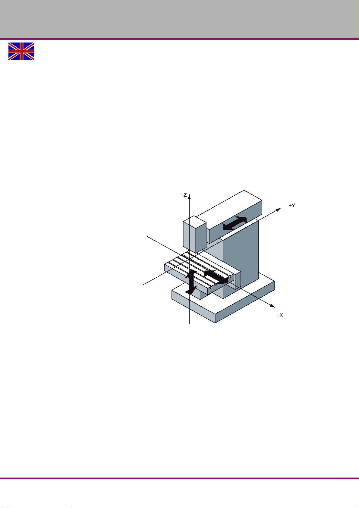
OPTIMUM
MASCHINEN - GERMANY
4.2.2 Polar coordinate system
In the Cartesian coordinate system a point is described by e.g. its X- and Y-coordinate. For
rotation-symmetric outlines, e.g. circular drilling images the required coordinates can only be
calculated with considerable effort.
In the polar coordinate system a point is described by means of its distance (radius r) to the
coordinate origin and its angle (a) to the defined axis. The angle (a) is related to the X-axis of
the X, Y coordinate system. In opposite direction it is negative.
4.2.3 Machine coordinate system
The machine coordinate system of the CNC- machine tool is determined by the manufacturer. It
cannot be changed. The position of the origin point for the machine coordinate system, also
called machine zero point cannot be changed.
Any tool moves are generally defined in a standardized, right-handed coordinate system.
Turns from +X to +Y are created in +Z direction, which result in a right-handed screw.
Z- axis:
According to the standard it is
equal to the working spindle or
continues in positive direction
starting from the workpiece.For
milling it continues directed to the
spindle perpendicular on the
clamping surface (only for perpendicular milling machines) for several spindles one main spindle is
determined.
X- axis:
Continues horizontally and parallel to the clamping surface
for vertical Z-axis: +X to the right
for horizontal Z-axis: +X to the left
.
Img.4-1: Vertical Z-axis
Y- axis:
At a right angle to the Z- and X- axis in a way that a right-handed coordinate system is resulting
4.2.4 Workpiece coordinate system
The workpiece coordinate system is determined by the programmer. It can be changed. The
location of the origin point for this workpiece coordinate system, also called workpiece origin
point is generally user-defined.
General information about CNC
Version 1.1.6 dated 2014-10-16 Page 51Original operating instructions
F150 GB
Page 52

OPTIMUM
MASCHINEN - GERMANY
4.2.5 Rotary axes and secondary axes
NC machines with rotary table or swivel head
Rotary axis: A B C
Positive turn around X, Y, Z (right- hand-rule)
NC machines with several feed axes
Secondary axis: U V W
Parallel to the X-,Y-,Z-axis
4.3 NC mathematics
4.3.1 Basics of the coordinate calculation
For the CNC programming the corresponding points of the outline which is to be machined
need to be entered. In most cases if the drawing is suitable for NC purposes, it is possible to
directly transfer these coordinate points from the drawing. In some cases it may be necessary
to calculate the coordinates.
In the frame of the automation those coordinates are calculated by an NC programming system at external working places and the data are directly transferred to the machine. Therefore,
in most cases the NC programming is directly performed on the product (3D pattern) in the construction or in the process engineering department.
For the computer-aided programming the switch and path information are entered over the keyboard in the dialogue using the menu technique.
4.3.2 Parameters of a triangle
In order to calculate the missing coordinates the relations valid for a triangle are very useful.
There are several options to describe a triangle. Some of the following parameters e.g. corners,
angles or sides are being used.
4.3.3 Angle on a triangle
The angles on a triangle determine the type of triangle. Depending on the size of the individual
angles we distinguish between acute-angle, obtuse angle or rectangular triangles.
On triangles the following relation is applied:
the sum of the angles a, b and g in a triangle always amounts to 180°.
a + b + g = 180°
If two angles are known it is possible to determine the third unknown angle by means of this
formula.
F150GB
General information about CNC
Version 1.1.6 dated 2014-10-16Page 52 Original operating instructions
Page 53

OPTIMUM
a
b
c
MASCHINEN - GERMANY
Rectangular triangle
The rectangular triangle has a special meaning in the analytic geometry as the sides of such a
triangle are having a definite mathematic relation to one another.
On a rectangular triangle the single sides are specially named.
The longest side is located opposite to the right angle and is named hypotenuse.
The two sides of the triangle which are forming the right angle are named cathetus.
The side opposite the angle a is named opposite leg.
The side adjacent to the angle a is named adjacent leg.
On a rectangular triangle the right angle is described by an quarter circle and a point in the
angle.
In a rectangular triangle it applies:
In a rectangular triangle you can calculate the missing leg if the other leg lengths are known. To
do so, use the Pythagorean theorem.
The Greek Pythagoras (from about 580 to 496 before Jesus Christ) had been the first person to
prove the following mathematic relation which had later on been named the Pythagorean theorem.
The sum of the cathetus square is equal to the hypotenuse square and expressed as a equation:
a² + b² = c²
4.4 Trigonometric functions
The trigonometric functions describe the relations between the angles and the sides of a rectangular triangle. With the help of these trigonometric functions it is possible to calculate
unknown leg lengths with an unknown angle and a known leg. It is depending on which side
and which angle are known in order to choose the appropriate trigonometric function e.g. the
sinus function, the cosine function or the tangent function.
For the calculation of unknown legs the corresponding equation needs to be transformed as
described in the following example:
Known are: the angle and the length of the adjacent leg
Looking for: the length of the opposite leg
It applies: tan alpha = opposite leg / adjacent leg
The results is:
opposite leg = adjacent leg x tan alpha
General information about CNC
Version 1.1.6 dated 2014-10-16 Page 53Original operating instructions
F150 GB
Page 54
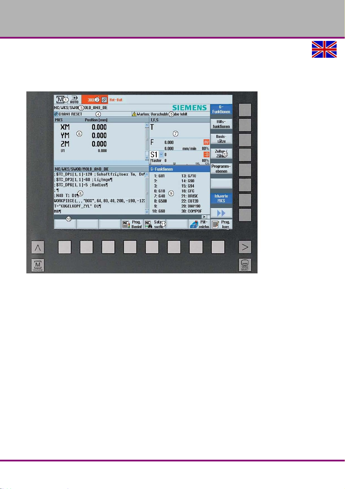
OPTIMUM
MASCHINEN - GERMANY
5 User interface, machine control panel
5.1 Screen arrangement
Excerpt from the manual of the operating instructions for "SINUMERIK 828 D"
Img.5-1: Screen arrangement
1. Active operating area and operating mode
2. Alarm-/message row
3. Program name
4. Channel condition and program influence
5. Channel operation messages
6. Position indication of the axes in the actual value window
7. Display for
- active tool T
- current feed F
- active spindle in current condition (S)
- Spindle utilization in percent
8. Working window including program record display
9. Display of active G functions, all G functions, H functions and input window for different functions (for example, skip blocks, program control)
10. Dialogue row for the transfer of additional user instructions
11. Horizontal softkey bar
12. Vertical softkey bar
F150GB
User interface, machine control panel
Version 1.1.6 dated 2014-10-16Page 54 Original operating instructions
Page 55
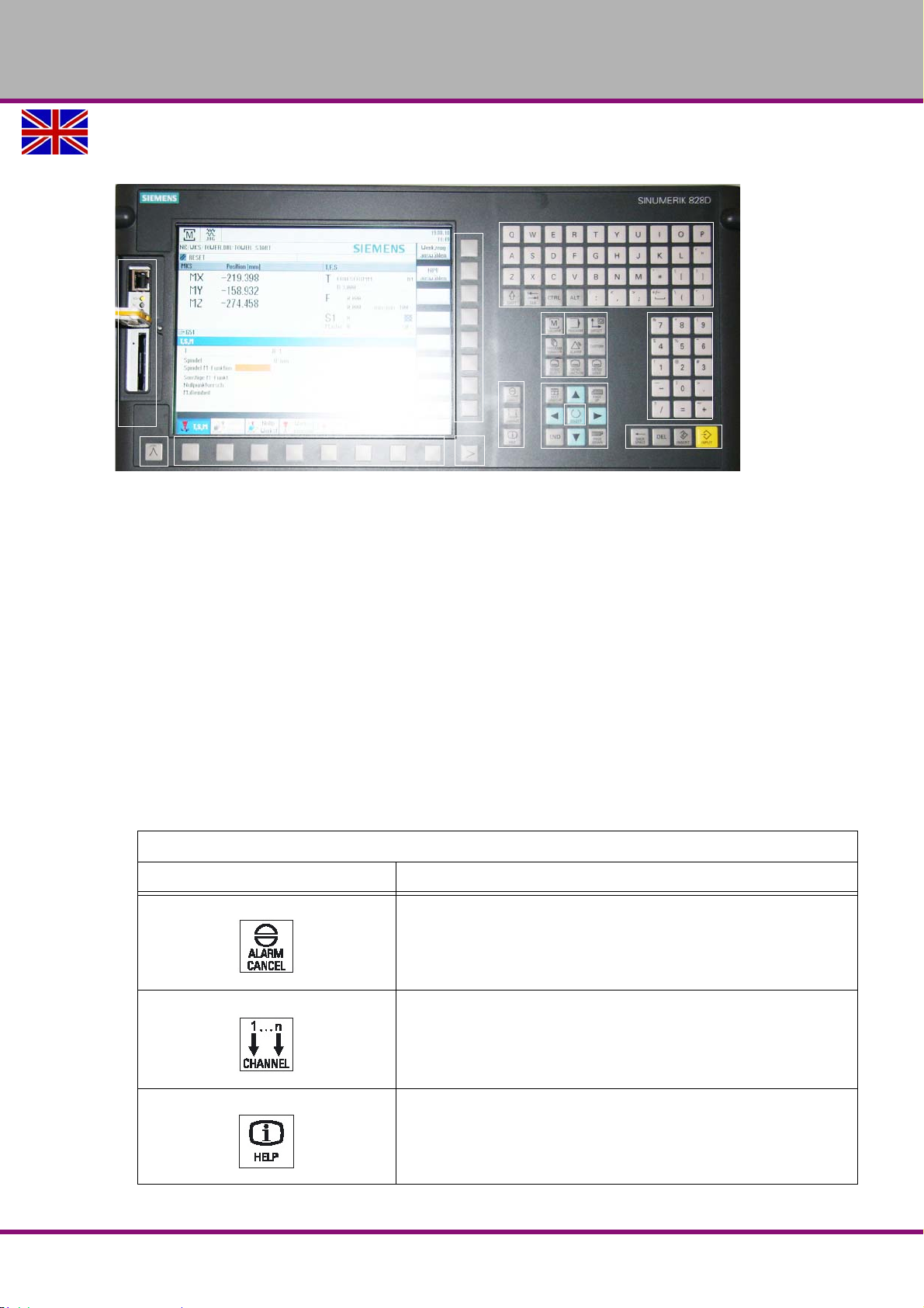
OPTIMUM
11
3
3
9
4
5
8
2
1
5
7
6
10
MASCHINEN - GERMANY
5.2 Key definition of the CNC full keyboard
Excerpt from the manual of the operating instructions for "SINUMERIK 828 D".
Img.5-2: Control panel
1. Alpha block
2. Numeric block
3. Softkeys
4. Control key block
5. Hotkey block
6. Cursor block
7. USB interface/ RS45/ CF card
8. Menu select key
9. Menu forward key
10.Machine area key
11.Menu forward key
5.2.1 Keys and key combinations on the control panel
Excerpt from the manual of the operating instructions for "SINUMERIK 828 D"
Key Function
<ALARM CANCEL>
Cancels alarms and messages that are marked with this symbol.
<CHANNEL>
Advances for several channels.
<HELP>
Calls the context-sensitive online help for the selected window.
User interface, machine control panel
Version 1.1.6 dated 2014-10-16 Page 55Original operating instructions
F150 GB
Page 56
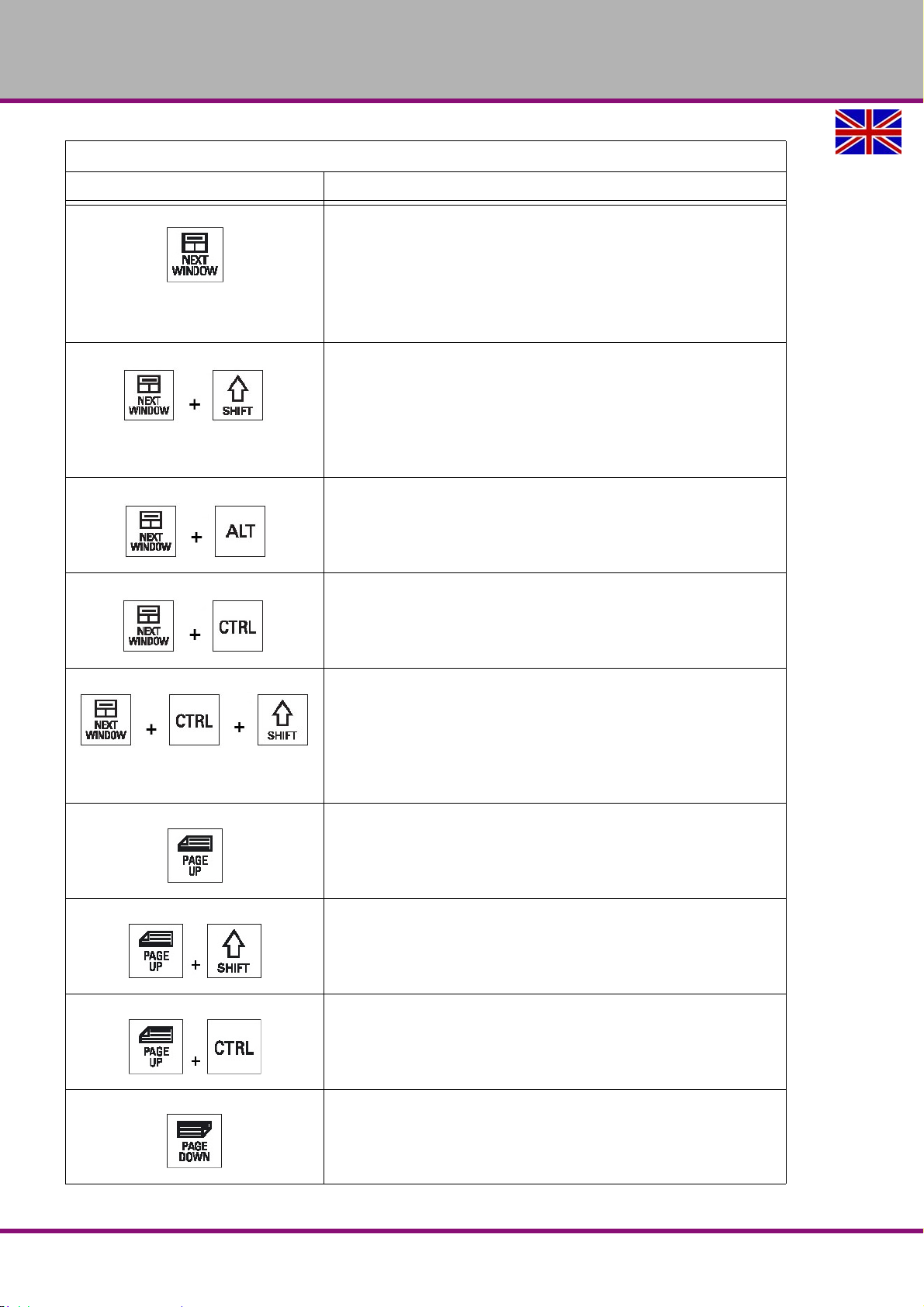
OPTIMUM
MASCHINEN - GERMANY
Excerpt from the manual of the operating instructions for "SINUMERIK 828 D"
Key Function
<NEXT WINDOW>
• Toggles between the windows.
• For a multi-channel view or for a multi-channel functionality, switches
within a channel gap between the upper and lower window.
• Selects the first entry in selection lists and in selection fields.
• Moves the cursor to the beginning of a text.
* on USB keyboards use the <Home> or <Pos 1> key
<NEXT WINDOW> + <SHIFT>
• Selects the first entry in selection lists and in selection fields.
• Moves the cursor to the beginning of a text.
• Selects a contiguous selection from the current cursor position up to
the target position.
• Selects a contiguous selection from the current cursor position up to
the beginning of a program block.
<NEXT WINDOW> + <ALT>
• Moves the cursor to the first object.
• Moves the cursor in the first column of a table row.
• Moves the cursor to the beginning of a program block.
<NEXT WINDOW> + <CTRL>
• Moves the cursor to the beginning of a program.
• Moves the cursor in the first row of the current column.
<NEXT WINDOW> + <CTRL> + <SHIFT>
• Moves the cursor to the beginning of a program.
• Moves the cursor in the first row of the current column.
• Selects a contiguous selection from the current cursor position up to
the target position.
• Selects a contiguous selection from the current cursor position up to
the beginning of the program.
<PAGE UP>
Scrolls upwards by one page in a window.
<PAGE UP> + <SHIFT>
In the program manager and in the program editor from the cursor
position, selects directories or program blocks up to the beginning of the
window.
<PAGE UP> + <CTRL>
Positions the cursor to the topmost line of a window.
<PAGE DOWN>
Scrolls downwards by one page in a window.
F150GB
User interface, machine control panel
Version 1.1.6 dated 2014-10-16Page 56 Original operating instructions
Page 57
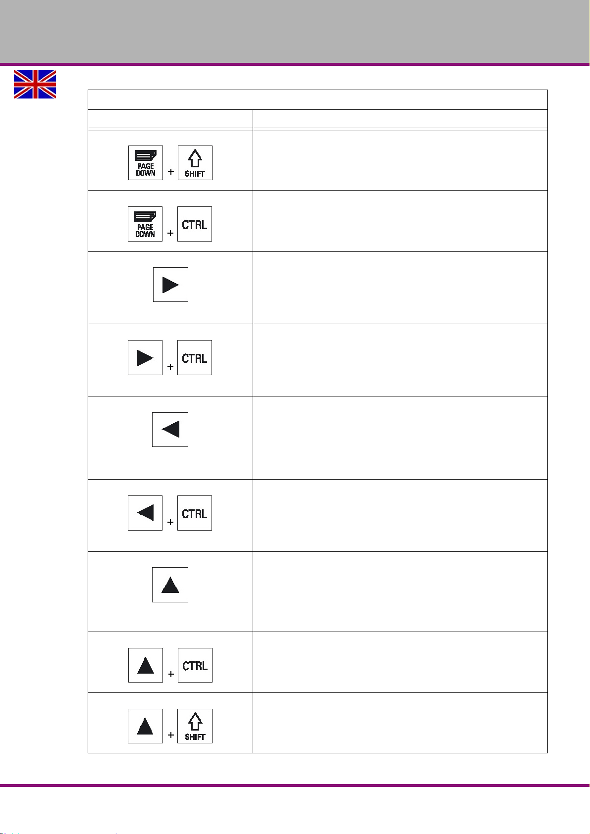
OPTIMUM
MASCHINEN - GERMANY
Excerpt from the manual of the operating instructions for "SINUMERIK 828 D"
Key Function
<PAGE DOWN> + <SHIFT>
In the program manager and in the program editor, from the cursor
position, selects directories or program blocks up to the end of the
window.
<PAGE DOWN> + <CTRL>
Positions the cursor to the lowest line of a window.
<Cursor right>
• Editing field
Opens a directory or program (e.g. cycle) in the editor.
• Navigation
Moves the cursor further to the right by one character.
<Cursor right> + <CTRL>
• Editing box
Moves the cursor further to the right by one word.
• Navigation
Moves the cursor in a table to the next cell to the right.
<Cursor left>
• Editing field
Closes a directory or program (e.g. cycle) in the program editor. If you
have made changed, then these are accepted.
• Navigation
Moves the cursor further to the left by one character.
<Cursor left> + <CTRL>
• Editing field
Moves the cursor further to the left by one word.
• Navigation
Moves the cursor in a table to the next cell to the left.
<Cursor up>
• Editing box
Moves the cursor into the next upper field.
• Navigation
- Moves the cursor in a table to the next cell upwards.
- Moves the cursor upwards in a menu screen.
<Cursor up> + <CTRL>
• Moves the cursor in a table to the beginning of the table.
• Moves the cursor to the beginning of a window.
<Cursor up> + <SHIFT>
In the program manager and in the program editor, selects a contiguous
selection of directories and program blocks.
User interface, machine control panel
Version 1.1.6 dated 2014-10-16 Page 57Original operating instructions
F150 GB
Page 58
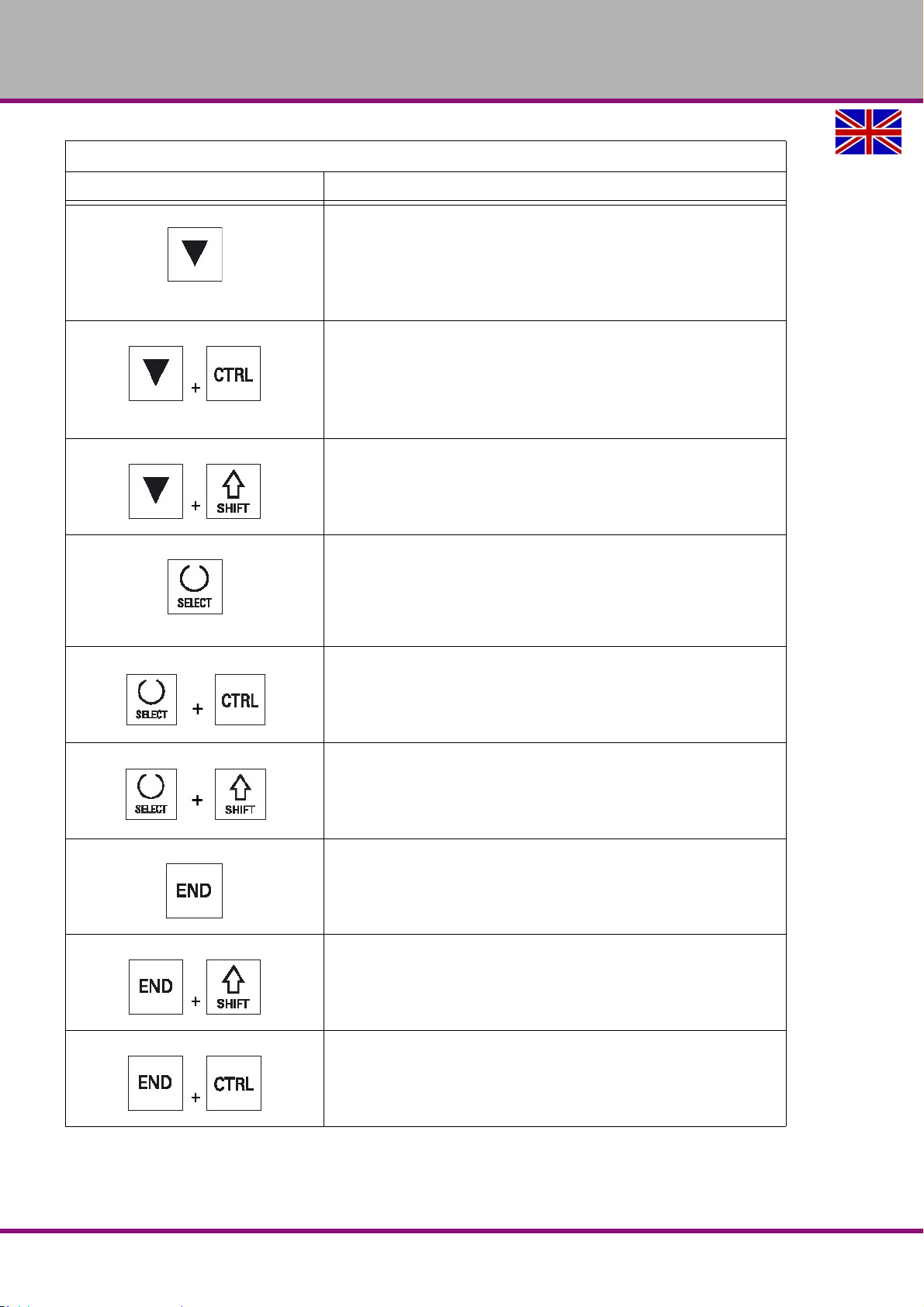
OPTIMUM
MASCHINEN - GERMANY
Excerpt from the manual of the operating instructions for "SINUMERIK 828 D"
Key Function
<Cursor down>
• Editing field
- Moves the cursor downwards.
• Navigation
- Moves the cursor in a table to the next cell downwards.
- Moves the cursor in a window downwards.
<Cursor down> + <CTRL>
• Navigation
- Moves the cursor in a table to the end of the table.
- Moves the cursor to the end of a window.
•Simulation
- Reduces the override.
<Cursor down> + <SHIFT>
In the program manager and in the program editor, selects a contiguous
selection of directories and program blocks.
<SELECT>
Toggles between entries in the input field.
Activates check boxes.
In the program editor and in the program manager, selects a program
block or a program.
<SELECT> + <CTRL>
When selecting table rows, switches between selected and not selected.
<SELECT> + <SHIFT>
Selects in selection lists and in selection fields the previous entry or the
last entry.
<END>
Moves the cursor to the last entry field in a window, to the end of a table
or a program block.
Selects the last entry in selection lists and in selection fields.
<END> + <SHIFT>
Moves the cursor to the last entry.
Selects a contiguous selection from the cursor position up to the end of
a program block.
<END> + <CTRL>
Moves the cursor to the last entry in the last line of the actual column or
to the end of a program.
F150GB
User interface, machine control panel
Version 1.1.6 dated 2014-10-16Page 58 Original operating instructions
Page 59
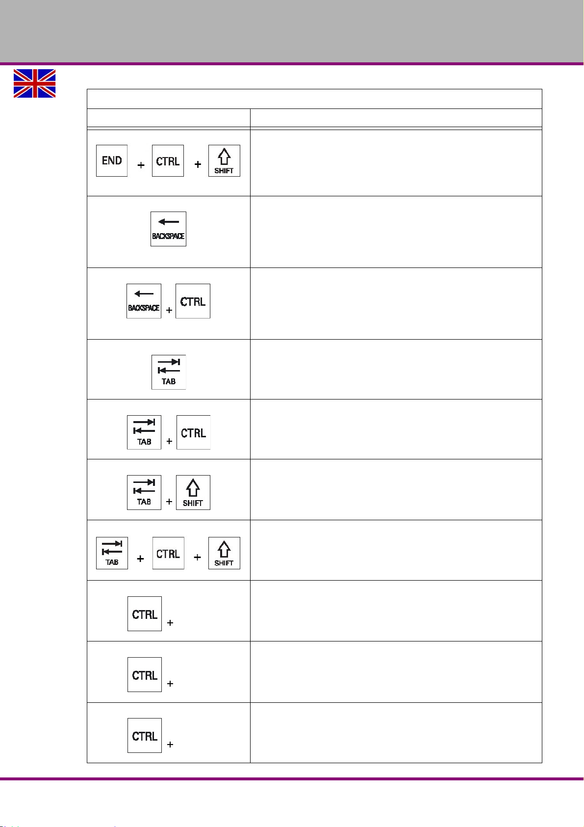
OPTIMUM
A+
<C>
<E>
MASCHINEN - GERMANY
Excerpt from the manual of the operating instructions for "SINUMERIK 828 D"
Key Function
<END> + <CTRL> + <SHIFT>
Moves the cursor to the last entry in the last line of the actual column or
to the end of a program.
Selects a contiguous selection from the cursor position up to the end of
a program block.
<BACKSPACE>
• Editing box
Deletes a character selected to the left of the cursor.
• Navigation
Deletes all of the selected characters to the left of the cursor.
<BACKSPACE> + <CTRL>
• Editing field
Deletes a word selected to the left of the cursor.
• Navigation
Deletes all of the selected characters to the left of the cursor.
<TAB>
• In the program editor, indents the cursor by one character.
• In the program manager, moves the cursor to the next right entry.
<TAB> + <CTRL>
• In the program editor, indents the cursor by one character.
• In the program manager, moves the cursor to the next right entry.
<TAB> + <SHIFT>
• In the program editor, indents the cursor by one character.
• In the program manager, moves the cursor to the next entry to the
left.
<TAB> + <CTRL> + <SHIFT>
• In the program editor, indents the cursor by one character.
• In the program manager, moves the cursor to the next entry to the
left.
<CTRL> + <A>
In the actual window, selects all entries (only in the program editor and
program manager).
<CTRL> + <C>
Copies the selected content.
<CTRL> + <E>
Calls the "Ctrl Energy" function.
User interface, machine control panel
Version 1.1.6 dated 2014-10-16 Page 59Original operating instructions
F150 GB
Page 60
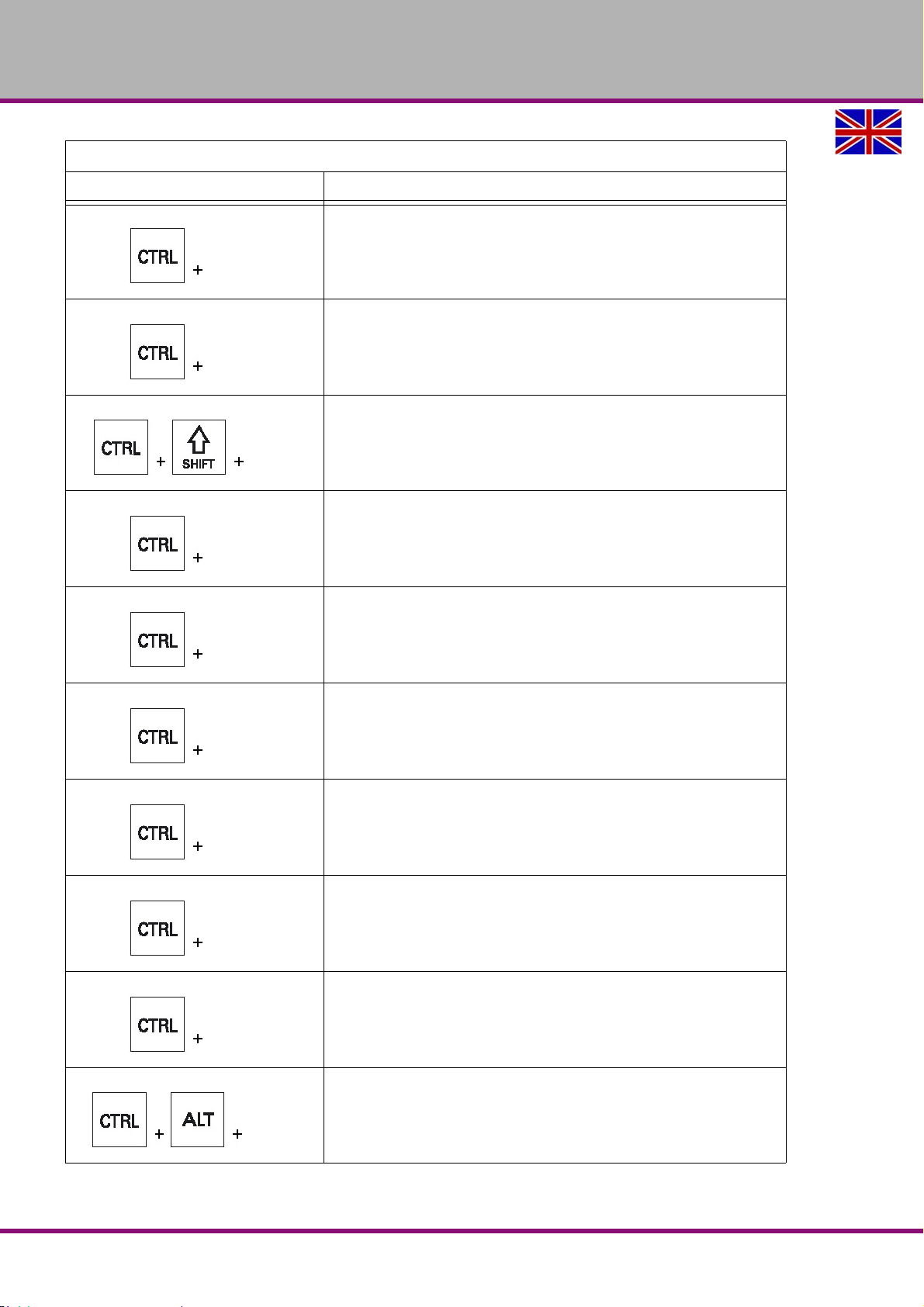
OPTIMUM
<F>
<L>
<L>
<P>
<S>
<V>
<X>
<Y>
<Z>
<C>
MASCHINEN - GERMANY
Excerpt from the manual of the operating instructions for "SINUMERIK 828 D"
Key Function
<CTRL> + <F>
Opens the search dialog in the machine data and setting data lists,
when loading and saving in the MDI editor as well as in the program
manager and in the system data.
<CTRL> + <L>
Scrolls the actual user interface through all installed languages one after
the other.
<CTRL> + <SHIFT> + <L>
Scrolls the actual operator interface through all installed languages in
the inverse sequence.
<CTRL> + <P>
Generates a screenshot from the actual operator interface and saves it
as file.
<CTRL> + <S>
Switches the single block in or out in the simulation.
<CTRL> + <V>
• Pastes the text from the clipboard at the actual cursor position.
• Pastes text from the clipboard at the position of a selected text.
<CTRL> + <X>
Cuts out the selected text. The text is located in the clipboard.
<CTRL> + <Y>
Reactivates changes that were undone (only in the program editor).
<CTRL> + <Z>
Undoes the last action (only in the program editor).
F150GB
<CTRL> + <ALT> + <C>
Creates a complete archive on an external data carrier
(USBFlashDrive).
User interface, machine control panel
Version 1.1.6 dated 2014-10-16Page 60 Original operating instructions
Page 61
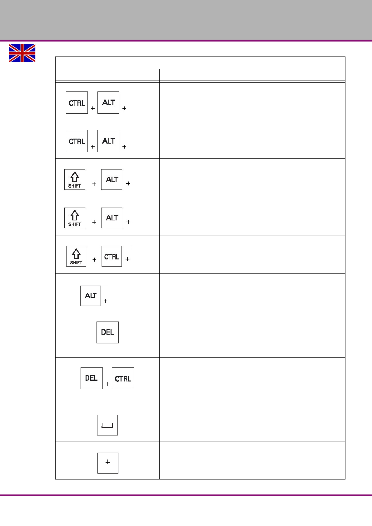
OPTIMUM
<S>
<D>
<D>
<T>
<T>
<S>
MASCHINEN - GERMANY
Excerpt from the manual of the operating instructions for "SINUMERIK 828 D"
Key Function
<CTRL> + <ALT> + <S>
Creates a complete archive on an external data carrier
(USBFlashDrive).
<CTRL> + <ALT> + <D>
Backs up the log files on the USB-FlashDrive. If a USBFlashDrive is not
inserted, then the files are backed-up in the manufacturer's area of the
CF-Card.
<SHIFT> + <ALT> + <D>
Backs up the log files on the USB-FlashDrive. If a USB Flash Drive is
not inserted, then the files are backed-up in the manufacturer's area of
the CF-Card.
<SHIFT> + <ALT> + <T>
Starts "HMI Trace".
<SHIFT> + <CTRL> + <T>
Exits "HMI Trace".
<ALT> + <S>
Opens the Editor to enter Asian characters.
<DEL>
• Editing box
Deletes the first character right of the cursor.
• Navigation
Deletes all characters.
<DEL> + <CTRL>
• Editing box
Deletes the first word to the right of the cursor.
• Navigation
Deletes all characters.
<Spacebar>
• Editing field
Editing field inserts a space
• Toggles between entries in the input field.
<Plus>
• Opens a directory, which contains the element.
• Increases the size of the graphic view for simulation and traces.
User interface, machine control panel
Version 1.1.6 dated 2014-10-16 Page 61Original operating instructions
F150 GB
Page 62
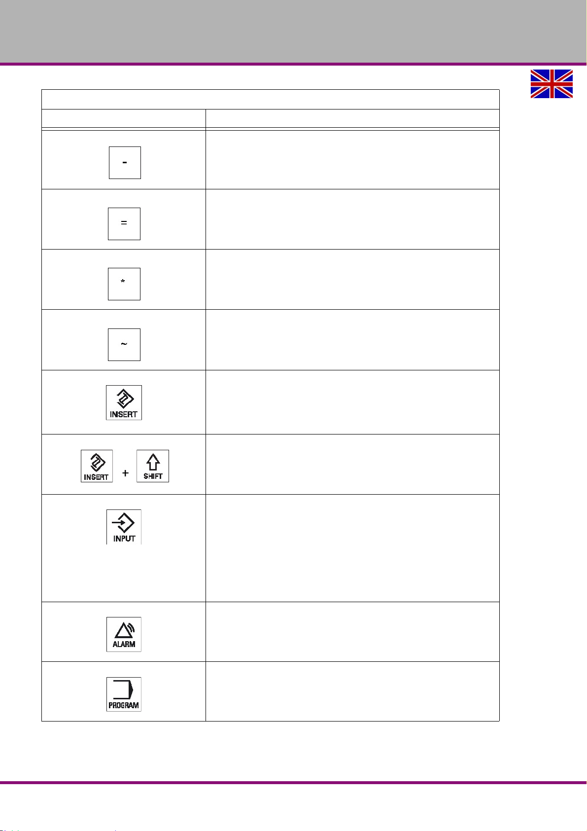
OPTIMUM
MASCHINEN - GERMANY
Excerpt from the manual of the operating instructions for "SINUMERIK 828 D"
Key Function
<Minus>
• Closes a directory, which contains the element.
• Reduces the size of the graphic view for simulation and traces.
<Equals>
Opens the calculator in the entry fields.
<Asterisk>
Opens a directory with all of the subdirectories.
<Asterisk>
Opens a directory with all of the subdirectories.
<INSERT>
• Opens an editing window in the insert mode. Press the key again,
exits the window and the entries are undone.
• Opens a selection box and shows the selection possibilities.
• In the machining step program, enters an empty line for G code.
<INSERT> + <SHIFT>
For G code programming, for a cycle call activates or deactivates the
edit mode.
<INPUT>
• Completes input of a value in the entry field.
• Opens a directory or a program.
• Inserts an empty program block if the cursor is positioned at the end
of a program block.
• Inserts a character to select a new line and the program block is split
up into 2 parts.
• In the G code, inserts a new line after the program block.
• In the machining step program, inserts a new line for G code.
<ALARM> - only OP 010 and OP 010C
Select the "Diagnosis" operating area.
<PROGRAM> - only OP 010 and OP 010C
Calls the "Program Manager" operating area.
F150GB
User interface, machine control panel
Version 1.1.6 dated 2014-10-16Page 62 Original operating instructions
Page 63
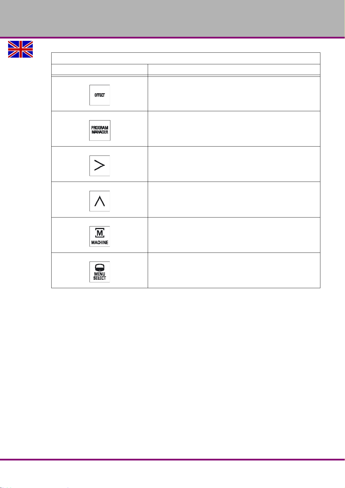
OPTIMUM
MASCHINEN - GERMANY
Excerpt from the manual of the operating instructions for "SINUMERIK 828 D"
Key Function
<OFFSET> - only OP 010 and OP 010C
Calls the "Parameter" operating area.
<PROGRAM MANAGER> - only OP 010 and OP 010C
Calls the "Program Manager" operating area.
Menu forward key
Advances in the extended horizontal softkey bar.
Menu back key
Returns to the higher-level menu.
<MACHINE>
Calls the "Machine" operating area.
<MENU SELECT>
Calls the main menu to select the operating area.
User interface, machine control panel
Version 1.1.6 dated 2014-10-16 Page 63Original operating instructions
F150 GB
Page 64
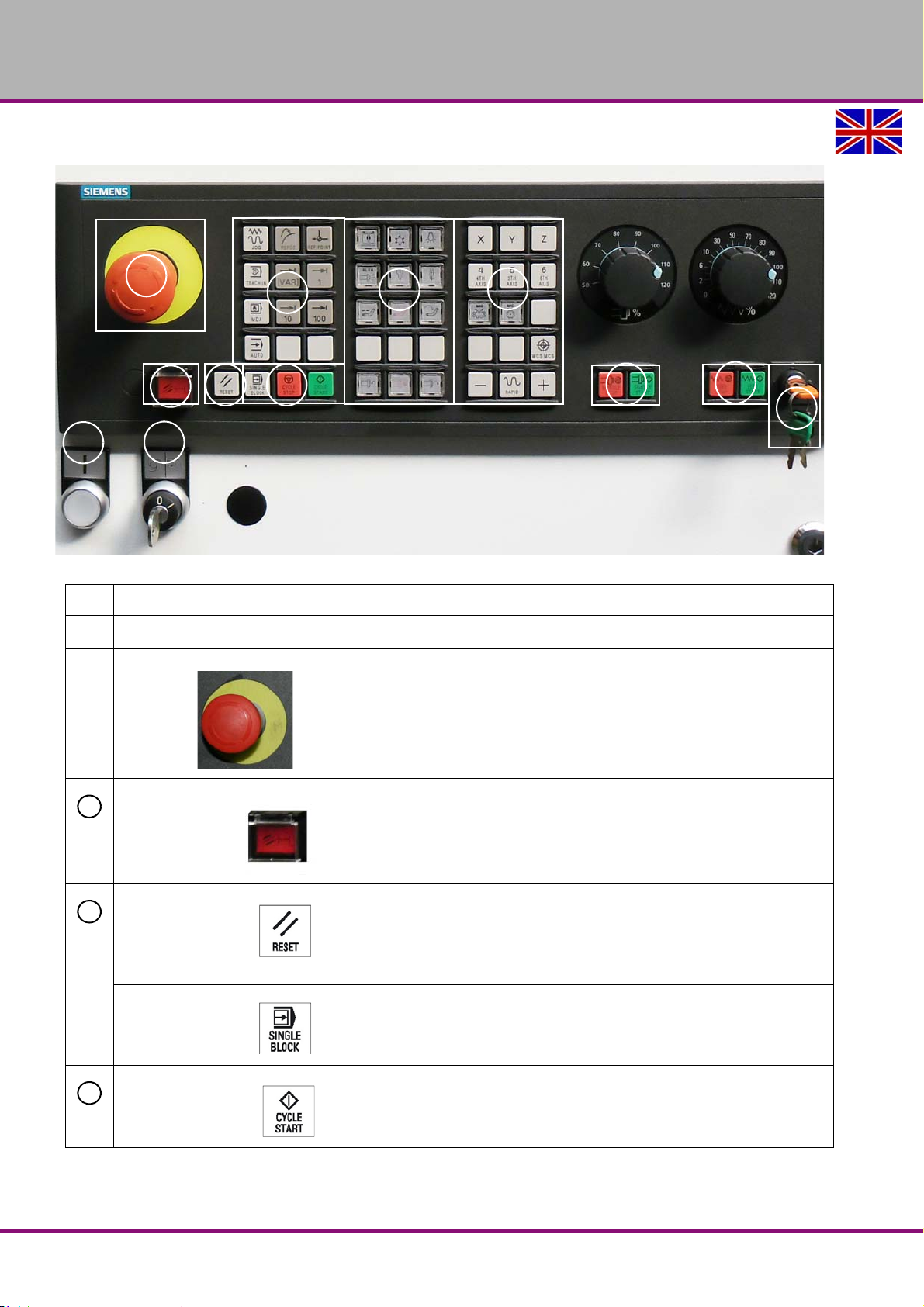
OPTIMUM
1
2
5
34
6
7
89
10
11
12
2
3
4
MASCHINEN - GERMANY
5.3 Controls on the machine control panel
Img.5-3: Machine Control Panel
Elements on the MCP
Element Function
<EMERGENCY STOP button>
Activate the button in situations where
• life is at risk.
• there is the danger of a machine or workpiece being damaged.
All drives will be stopped with the greatest possible braking torque.
not used
<RESET>
• Stop processing the current programs.
The NCK control remains synchronized with the machine. It is in its
initial state and ready for a new program run.
• Cancel alarm.
<SINGLE BLOCK>
Single block mode on/off.
F150GB
<CYCLE START>
The key is also referred to as NC Start.
Execution of a program is started.
Version 1.1.6 dated 2014-10-16Page 64 Original operating instructions
Page 65
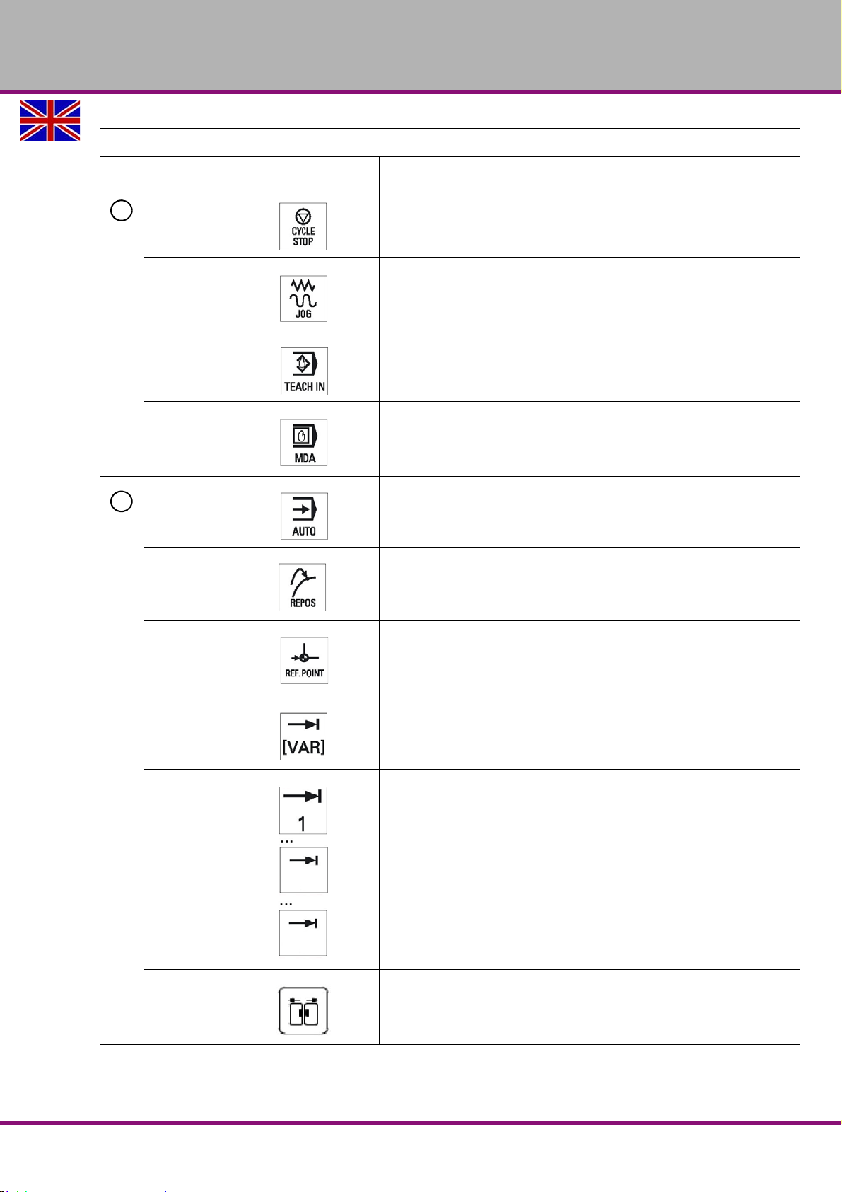
Elements on the MCP
4
5
10
100
Element Function
OPTIMUM
MASCHINEN - GERMANY
<CYCLE STOP>
The key is also referred to as NC Stop.
Execution of a program is stopped.
<JOG>
Select "JOG" mode.
<TEACH IN>
Select "Teach In" submode.
<MDI>
Select "MDI" mode.
<AUTO>
Select "AUTO" mode.
<REPOS>
Repositions, re-approaches the contour.
<REF POINT>
Approach reference point.
Inc <VAR>(Incremental Feed Variable)
Incremental mode with variable increment size.
Inc (Incremental feed)
Incremental mode with predefined increment size of 1, 10, 100
increments.
Door open / close
F150 GB
Version 1.1.6 dated 2014-10-16 Page 65Original operating instructions
Page 66
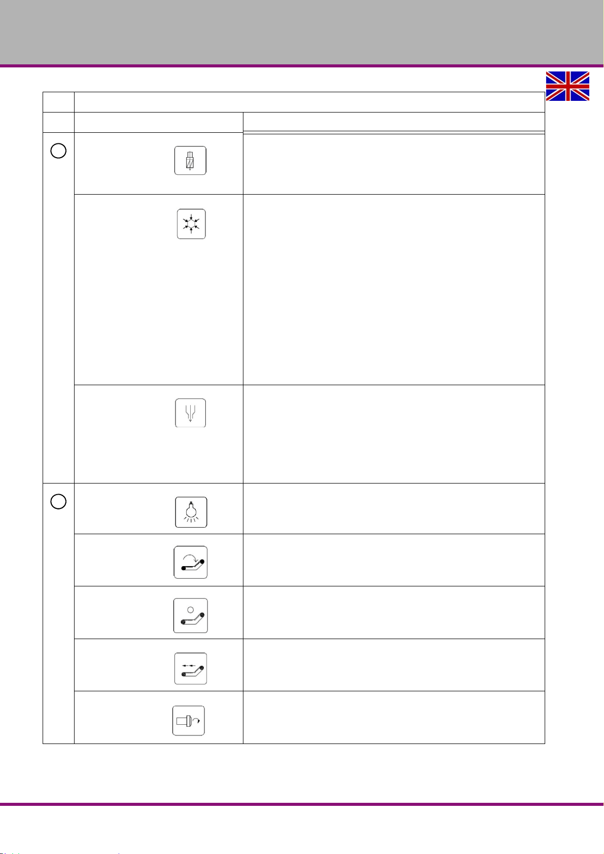
OPTIMUM
5
6
MASCHINEN - GERMANY
Elements on the MCP
Element Function
Function not used in the standard delivery.
Option - Coolant through spindle
Command M7 = Coolant through spindle "On"
Command M9 = Coolant through spindle "Off"
<Coolant> Manual Coolant On/Off Control
• Press the button to manually turn on the cooling.
• Press the button again to turn off the cooling system. Command M8
"Coolant On", M9 "Coolant Off".
The following conditions must be met for.
• Front door is closed.
• M01 is not active.
• Alarm 700 064 (Waiting for tool change) is not active.
• Alarm 700 153 (Main spindle pause) is not active.
• Alarm 700 156 (Tool changer not at home position, Spindle stop) is
not active.
The LED above the push button starts to flash when:
• By pressing the button or the command M8, the conditions are not
met.
Img.3-13: “Spindle cooling“ on page 36
<Chip flushing>
Press the push-button in order to switch on the chip flushing. By
pressing the push-button once again, the chip flushing is switched off
again.
Command M12 = Chip flushing ON
Command M9 = Chip flushing OFF
Img.3-14: “Chip flushing“ on page 36
<Working Light>
ON / OFF
<Chip conveyor forward>
Program command M24 = Chip conveyor ON
Program command M25 = Chip conveyor OFF
<Chip conveyor Stop>
Press the push-button Chip conveyor Stop or the push-button <RESET>
in order to stop the chip conveyor.
<Chip conveyor reverse>
Only for easy retracting the screw conveyor.
<Spindle CW>
Direction of rotation clockwise
It is not possible to activate the system in the automatic mode.
F150GB
Version 1.1.6 dated 2014-10-16Page 66 Original operating instructions
Page 67
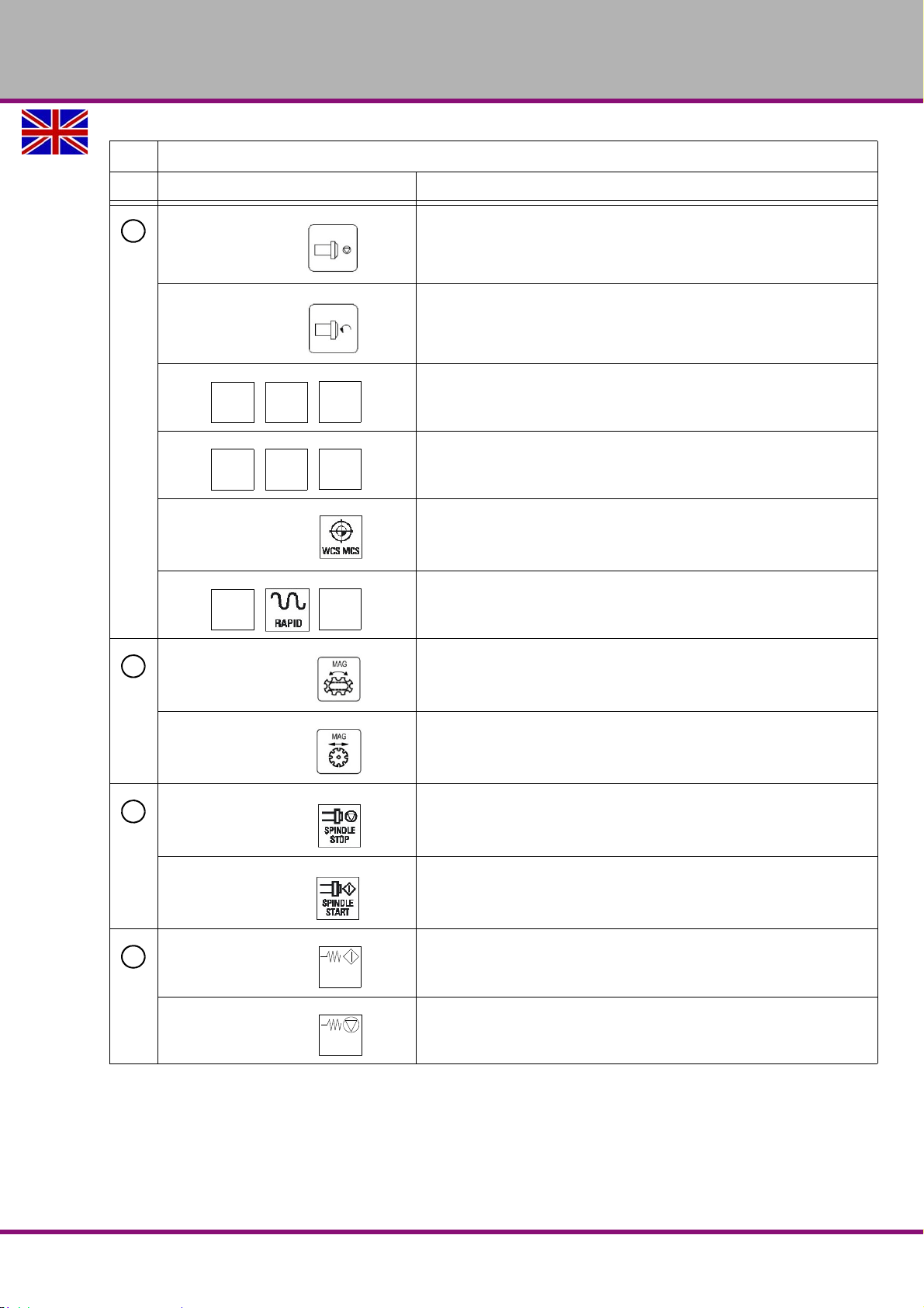
Elements on the MCP
6
X
Y
Z
4
5
6
4TH
AXIS
5TH
AXIS
5TH
AXIS
-
+
7
8
9
FEED
START
FEED
STOP
Element Function
OPTIMUM
MASCHINEN - GERMANY
<Spindle - Stop>
It is not possible to activate the system in the automatic mode.
<Spindle CCW>
Direction of rotation counter-clockwise
It is not possible to activate the system in the automatic mode.
<Axis keys>
Select axis.
not used
<WCS MCS>
Switch over between the tool coordinate system and
the machine coordinate system.
<RAPID>
Travel axis in the rapid traverse while pressing the direction key + or -
<MAG Turn> Rotate tool changer
"Manual operation of the tool changer“ on page 76
<MAG Move> Move tool changer
"Manual operation of the tool changer“ on page 76
<SPINDLE STOP>
Stop spindle
<SPINDLE START>
Spindle is released
<FEED START>
Releasing for processing of the program in the current record as well as
releasing to starting-up to the feed value preset by the program.
<FEED STOP>
Stopping processing of the current program and stopping axes drives
F150 GB
Version 1.1.6 dated 2014-10-16 Page 67Original operating instructions
Page 68
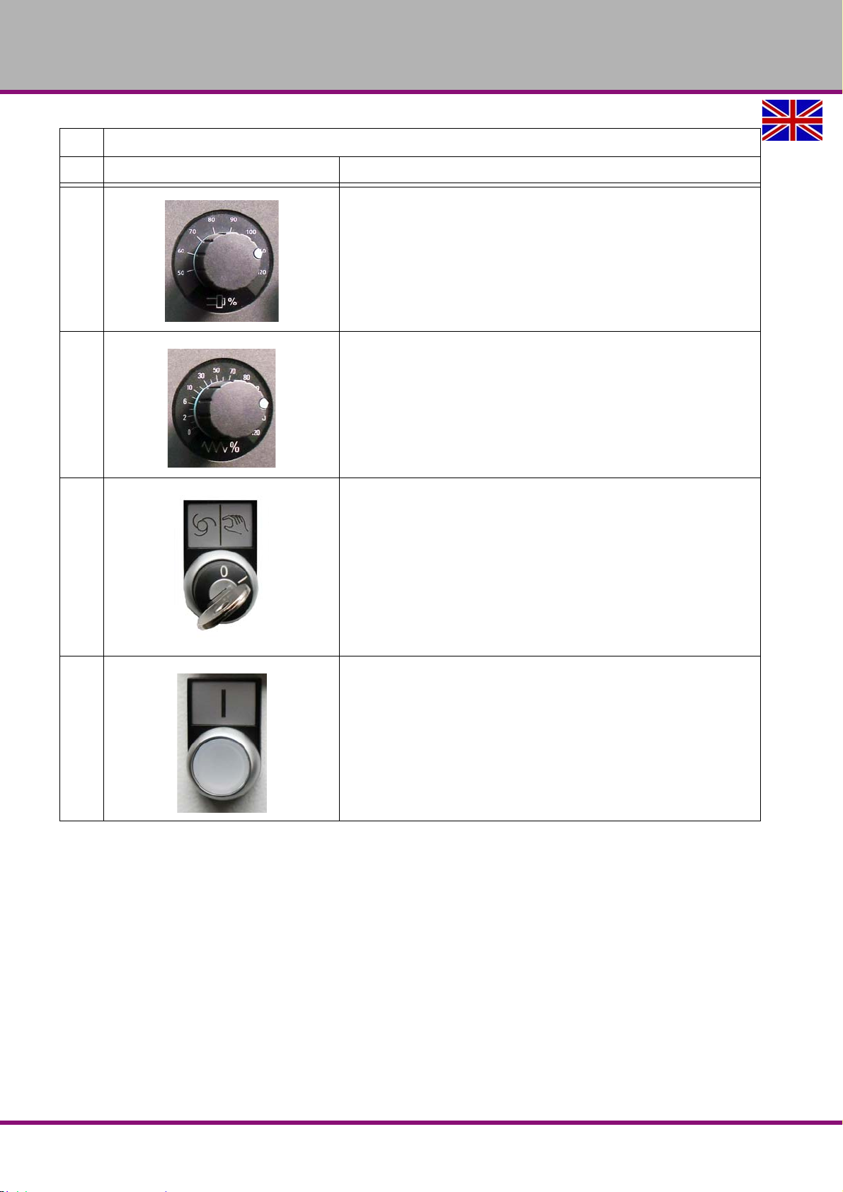
OPTIMUM
MASCHINEN - GERMANY
Elements on the MCP
Element Function
Increases or reduces the programmed speed.
The programmed spindle speed is set to 100% and can be controlled
from 50 to 120%.
The new spindle speed settings are displayed as an absolute value in
percent in the spindle status display on the screen.
Increases or reduces the programmed infeed.
The programmed infeed or rapid speed is set to 100% and can be set
from 0% to 120% (only up to 100% in the rapid traverse).
The new infeed settings are displayed as an absolute value in percent in
the infeed status display on the screen.
<0> <1> Setting mode
• Position <0> "Safety Integrated" function activated
• Position <1> "Safety Integrated" function deactivated
Drive voltage
Push-button with indicator light
• Indicator light ON, drive voltage activated
• Indicator light OFF, drive voltage deactivated
F150GB
Version 1.1.6 dated 2014-10-16Page 68 Original operating instructions
Page 69
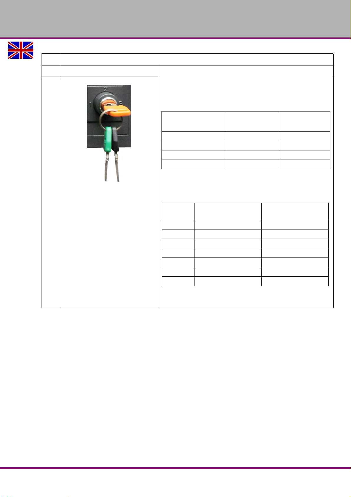
Elements on the MCP
Key colour
possible
Position
for
access stage
No key required <0> 7
Black <0> <1> 6 - 7
Green <0> <1> <2> 5 - 7
Orange <0> <1> <2> <3> 4 - 7
access
stage
Provided for: Protected by:
1 Manufacturer Password: SUNRISE
2 Service Password: EVENING
3 User Password: CUSTOMER
4 Operator: Programmer Key position <3>
5 Operator: Technician Key position <2>
6 Operator: Supervisor Key position <1>
7 Operator: Worker Key position <0>
Element Function
OPTIMUM
MASCHINEN - GERMANY
5.3.1 Key switch
<1> <2> <3>
Access rights of three keys:
The key switch is located at the bottom right of the machine control
panel and has got four positions. Three colour-coded key is available
allowing access to another access stage with each key.
Version 1.1.6 dated 2014-10-16 Page 69Original operating instructions
Example: The area machine data is not available unless access stage 4
(key position 3) or higher is released.
F150 GB
Page 70

OPTIMUM
MASCHINEN - GERMANY
F150GB
Version 1.1.6 dated 2014-10-16Page 70 Original operating instructions
Page 71
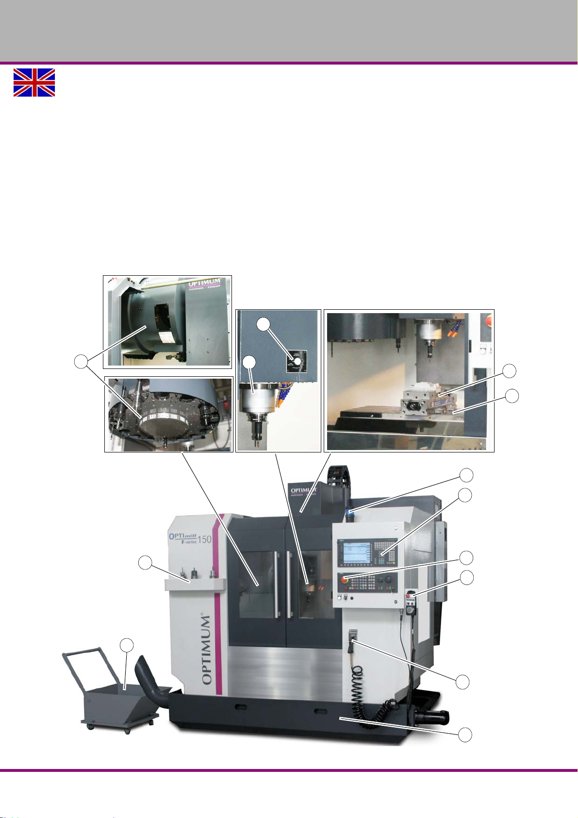
OPTIMUM
4
5
1
2
6
8
9
10
7
13
3
11
12
MASCHINEN - GERMANY
6 Operation
6.1 Safety
Commission the CNC machine only under the following conditions:
The CNC machine is in proper working order.
The CNC machine is used as prescribed.
The operating manual is followed.
All safety devices are installed and activated.
All failures should be eliminated immediately. Stop the CNC machine immediately in the event
of any abnormality in operation and make sure it cannot be started up accidentally or without
authorisation. Notify the person responsible immediately of any modification.
"Safety during operation“ on page 17
6.2 Control and indicating elements
Img.6-1: F150
Operation
Version 1.1.6 dated 2014-10-16 Page 71Original operating instructions
F150 GB
Page 72
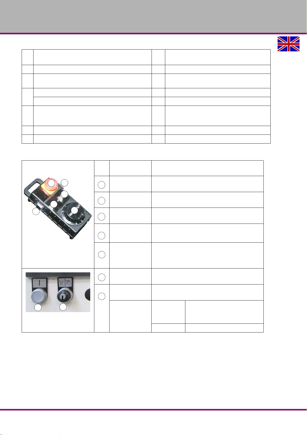
OPTIMUM
6
7
8
9
10
10
678
9
10
1
11
1
11
MASCHINEN - GERMANY
No
.
1 Touch-switch to release and clamp the tool 7 Milling table
Milling spindle
2
16-type tool change system 9 Machine Control Panel
3
24-type optional tool change system 10 Emergency-stop push button
Tool deposit (17 spaces)
4
5 Chip collection container 12 Cleaning gun
6 Machine vice (optional) 13 Coolant / lubricant tank / chip conveyor
Designation
Signal lamp (if the signal lamp is illuminated -->
8
CNC- program is running)
Handwheel for manual travelling with Emer-
11
gency Stop push button and acknowledgement
button
6.2.1 Operating the handwheel for manual travelling
Pos.
No
Designation Description
Rotary switch Selector switch to control the individual axis.
Rotary switch
Selector switch for the feed speed
(3 stages).
Hand wheel Handwheel to travel the individual axes.
Emergency-stop
push button
Push button resp.
acknowledge-
ment button
Drive tension ON Switches the control circuit of the servo motors
Key switch
Switch position
The EMERGENCY STOP push button switches off
the CNC machine.
In the setting mode resp. if the sliding door is open it
is necessary to actuate the acknowledgement button
in order to expressively allow the movement of the
individual axes.
Safety switch to activate or
deactivate the tool setting operation
0
1 Setting mode
Setting mode is not available
CNC program processing enabled
possible
F150GB
Operation
Version 1.1.6 dated 2014-10-16Page 72 Original operating instructions
Page 73
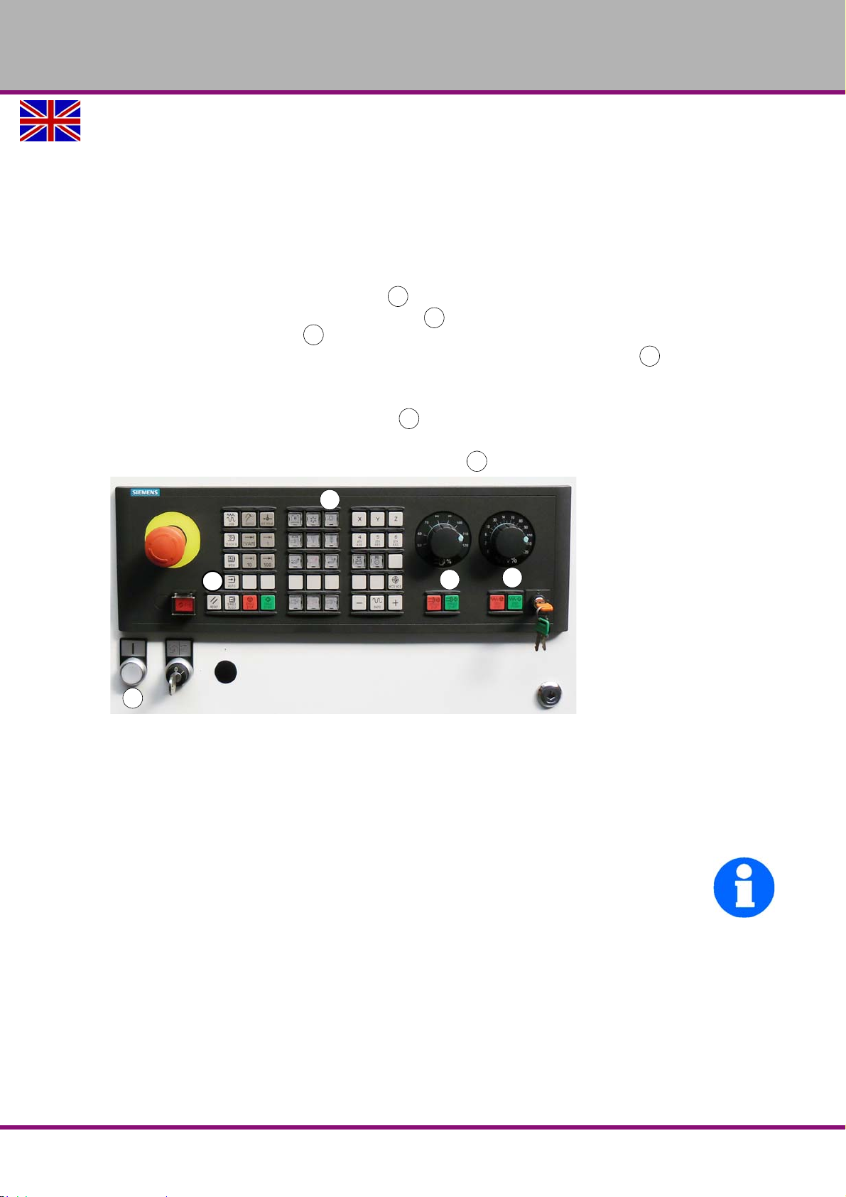
OPTIMUM
123
4
5
4
4
2
3
1
5
MASCHINEN - GERMANY
6.3 Switching on the CNC machine
When switching on the machine the integrated safety functions of the machine
"Safety Integrated" are checked and scanned. Please proceed in the following sequence:
Switch on the main switch.
"Lockable main switch“ on page 14
Please wait until the control is completely started.
Unlock the "Emergency-Stop buttons".
"EMERGENCY STOP push button“ on page 15
Press the push button "Drive control ON" .
First press the push button "SPINDLE START" and then the
push button "FEED START"
Acknowledge the upcoming error message by pressing the push button "RESET".
On the Display the message 700033 "Door check" is displayed. Open and close the door once
in order to perform a safety test. Therefore, perform the following steps.
Press the push button "Open - Close door"
Open and completely close the door.
After closing the door, press the push button "RESET"
Img.6-2: Control panel
If possible, read the upcoming messages on the display, remove the error messages, such
as e.g. insufficient compressed air, insufficient coolant / lubricant.
and error messages“ on page 86
"Notes, messages
For the following working steps, please proceed as described in chapter 2 „Operation and
programming“ of the Siemens „SINUMERIK 828 D" Operation instructions.
INFORMATION
Your CNC machine is equipped with an absolute measuring system.
A travel to reference point after power on is not necessary.
Operation
F150 GB
Version 1.1.6 dated 2014-10-16 Page 73Original operating instructions
Page 74
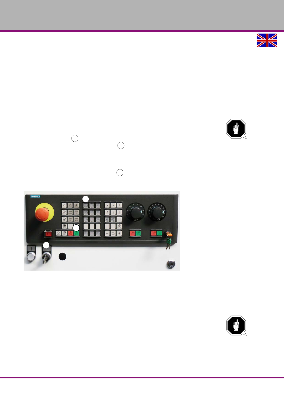
OPTIMUM
123
3
2
1
MASCHINEN - GERMANY
6.4 Switching off the CNC machine
Push the EMERGENCY STOP push button.
For a long-term standstill of the CNC machine switch it off at the main switch.
"Disconnecting and securing the CNC machine“ on page 18
6.5 First insertion of a tool
When first commissioning the machine, the spindle is not located in a defined position. There is
no saved position in the control which indicates if there is a tool inserted in the spindle.
The message 700088 "Empty the tool spindle" is displayed.
In order to remove the non defined position, perform the following working steps for safety
reasons.
ATTENTION!
Hold your tool if there is a tool inserted in the spindle.
Turn the key switch to the position <0>
Press the push button "Open/Close door" and open the door.
Press the push button once before releasing the tool.
Img.6-4: “Manual tool change“ on page 75
Close the door again.
Press the push button <CYCLE START>
The axis travels to its maximum position, then close and open once the pneumatic acceleration
of the tool. Thus the process is completed.
Img.6-3: Control panel
6.6 Insert tool
If you are working with only one tool which is directly inserted in the spindle it is possible to perform the inserting resp. changing in the operating mode "JOG". Press the corresponding push
button at the spindle head in order to "loosen" or to "clamp" the tool pneumatically.
ATTENTION!
Firmly hold the tool when you press the push button for "loosening".
F150GB
Operation
Version 1.1.6 dated 2014-10-16Page 74 Original operating instructions
Page 75
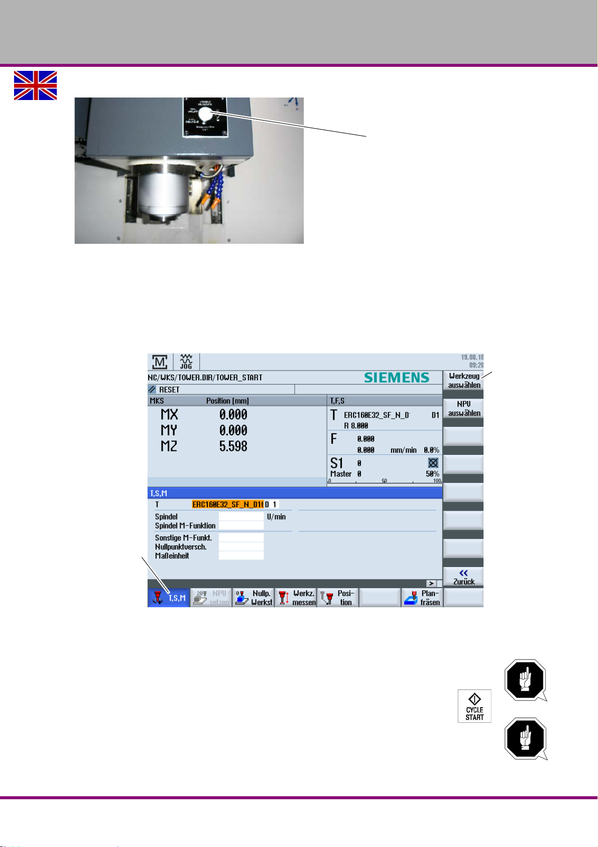
OPTIMUM
Push button
Softkey button
"Select tool"
Softkey button
„T, S, M"
MASCHINEN - GERMANY
Img.6-4: Manual tool change
When inserting a tool for the first time, please observe "First insertion of a tool“ on page 74
In case that you are working using the tool changer and you would like to insert new tools you
must change to the operating mode <JOG> (Jog mode) "T, S, M“ since it is only possible to
change the tool via the spindle.
Manually change the tool in the spindle as described above. Perform the following com-
mands for changing resp. replacing.
Operation
Version 1.1.6 dated 2014-10-16 Page 75Original operating instructions
Press the softkey button "T, S, M".
Actuate the softkey "Select tool".
NOTE!
The tool must be created in the tool magazine.
Select the tool by means of the arrow key and press <CYCLE START>. The tool
in the tool magazine is changed.
NOTE!
The tool is displayed in the tool list.
F150 GB
Page 76
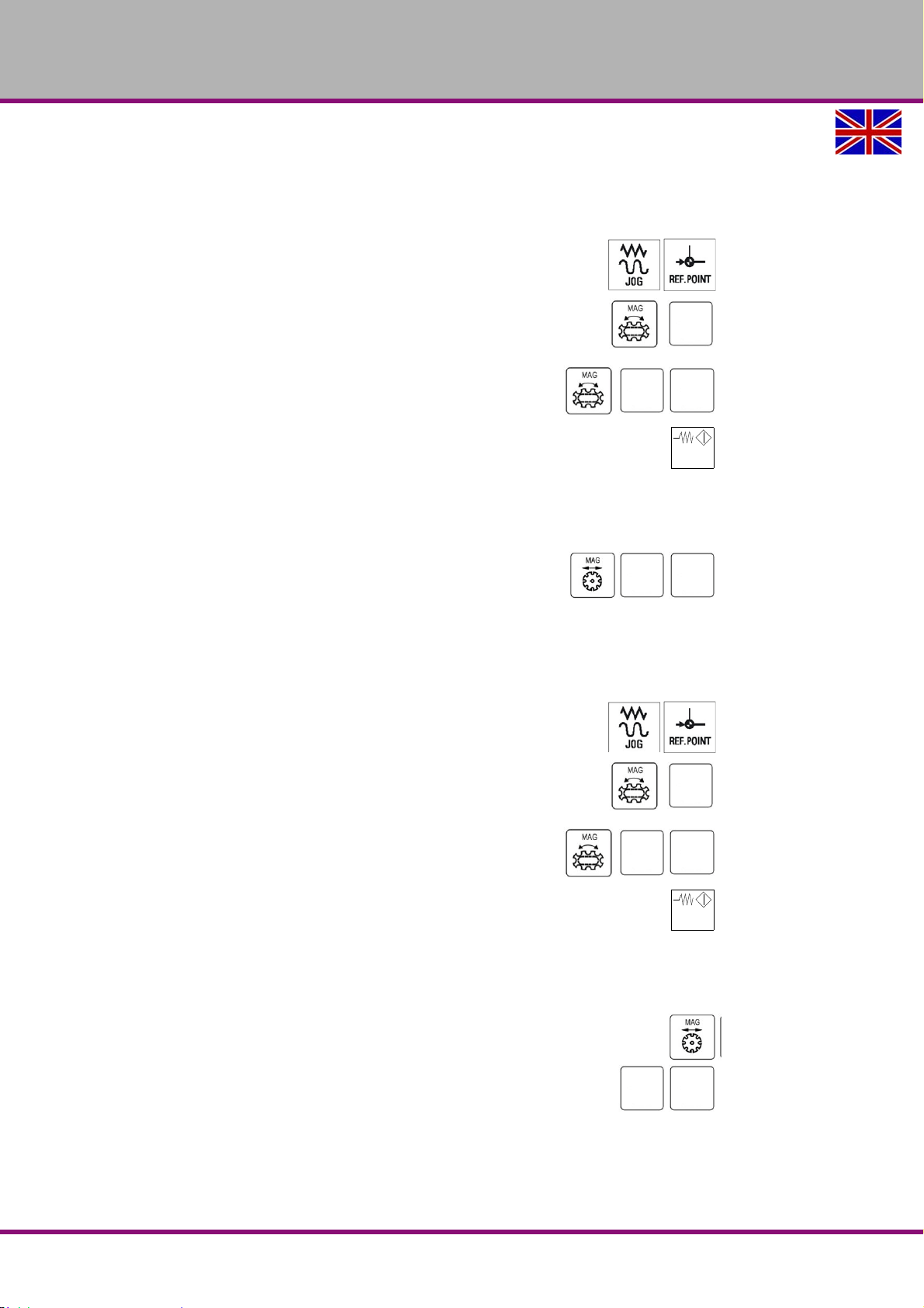
OPTIMUM
+
+
-
FEED
START
+--++
-
FEED
START
+
-
MASCHINEN - GERMANY
6.7 Manual operation of the tool changer
6.7.1 Manual operation of the 16-type tool changer
The operator can manually travel the tool changer to the reference point
Press the key <JOG> and <REF.POINT> on the machine control panel in
order to access the mode "Reference point approach".
Press the key <MAG> and <+> in order to release the travelling of the
tool changer
Press the key <Turn MAG> and <+> or
<MAG> and <-> in order to turn the tool changer to the desired
direction.
Press the key <FEED START> on the control panel of the machine 3 times contin-
uously. The LED via the key <FEED START> starts flashing and the message
700095 *** Service mode*** is displayed. Then the system goes to the ATC service mode.
When the system has accessed the ATC-Service mode and the Z-axis and the spindle are in
the tool changing position, the operator can manually operate the tool changer.
Press the key <Move MAG> and <+> or
<Move MAG> and <-> in order to move the tool changer to the
desired direction. The key <
change position.
+> moves the tool changer to the tool
6.7.2 Manual operation of the 24-type tool changer
The operator can manually travel the tool changer to the reference point
Press the key <JOG> and <REF.POINT> on the machine control panel in
order to access the mode "Reference point approach".
Press the key <MAG> and <+> in order to release the travelling of the
tool changer
Press the key <Turn MAG> and <+> or
<MAG> and <-> in order to turn the tool changer to the desired
direction.
Press the key <FEED START> on the control panel of the machine 3 times contin-
uously. The LED via the key <FEED START> starts flashing and the message
700095 *** Service mode*** is displayed. Then the system goes to the ATC service mode.
When the system has accessed the ATC-Service mode and the Z-axis and the spindle are in
the tool changing position, the operator can manually operate the tool changer.
Press the key <move MAG> and the tool changer moves down to the tool
change position.
The key <+> and <-> moves the double arm of the tool changer .
6.7.3 Quit the ATC-Service mode
Press the key <FEED START> or <FEED STOP> or <RESET> on the machine control
panel in order to quit the ATC-Service mode.
F150GB
Version 1.1.6 dated 2014-10-16Page 76 Original operating instructions
Operation
Page 77
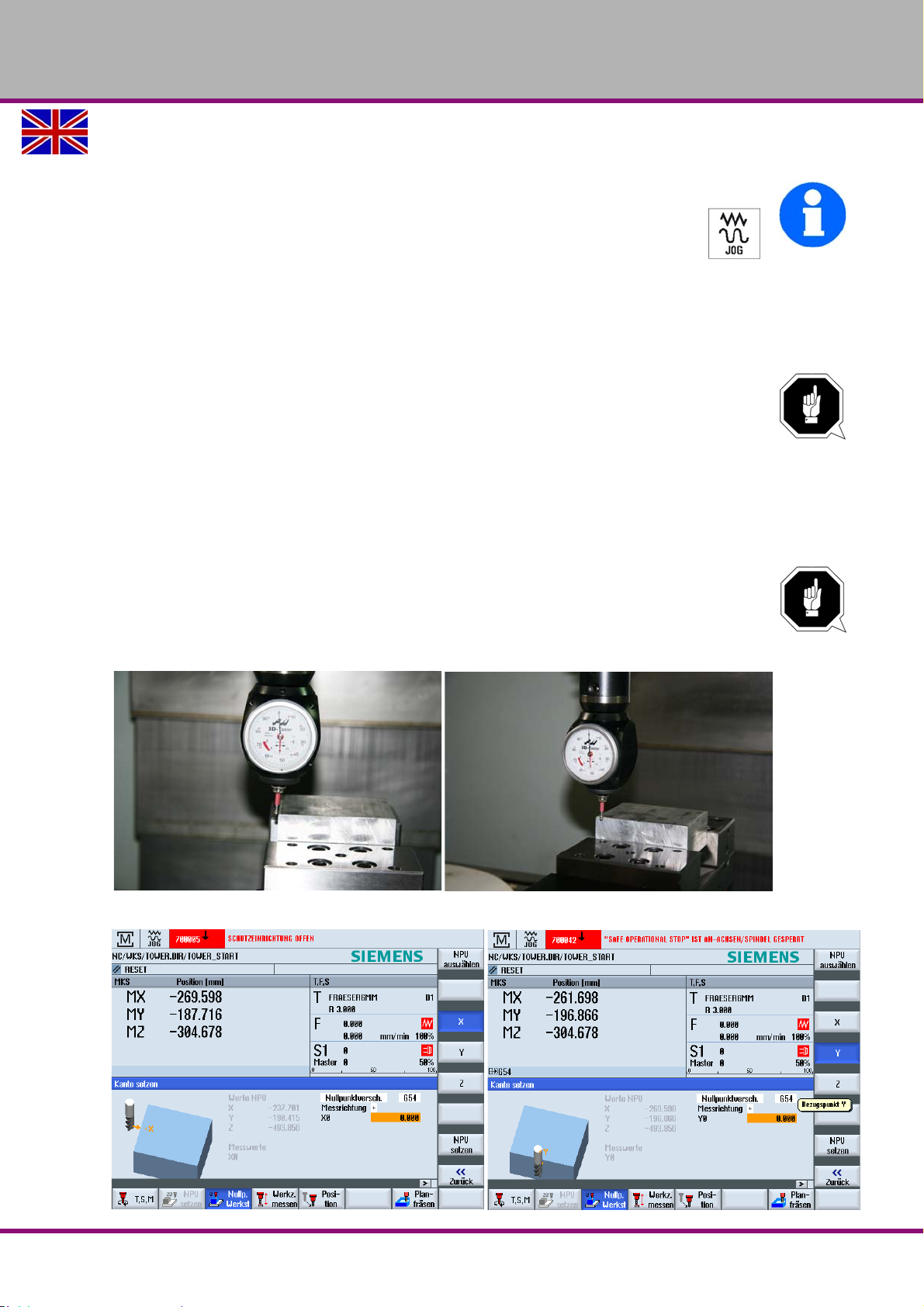
OPTIMUM
MASCHINEN - GERMANY
6.8 Setting
INFORMATION
For the setup operation <JOG> (JOG operation) the sliding door for the separating
protective equipment can be opened.
In the setting mode resp. if the sliding door is open it is necessary to actuate the
acknowledgement button in order to expressively allow the movement of the
individual axes.
Refer to chapter 4 "Setup machine" of the operating instructions for "SINUMERIK 828 D".
6.8.1 Clamping workpiece and setting workpiece datum
ATTENTION!
Clamp your workpiece safely and firmly on the milling table using appropriate clamping
devices. When setting and using already created programs observe the safety clearance
in order to avoid collisions with the selected clamping means.
Use a 3D calliper or another appropriate measuring device in order determine the work-
piece zero point.
Travel the X and Y axis using the handwheel until the 3D measuring probe indicates the
value "0".
NOTE!
If you use a milling cutter to measure the workpiece datum the milling cutter radius is automatically calculated. Enter it for the zero offset.
Press the button "Workpiece datum". Select the button X resp. Y axis.
Img.6-5: Determine workpiece datum X axis resp. Y axis
Operation
Version 1.1.6 dated 2014-10-16 Page 77Original operating instructions
F150 GB
Page 78
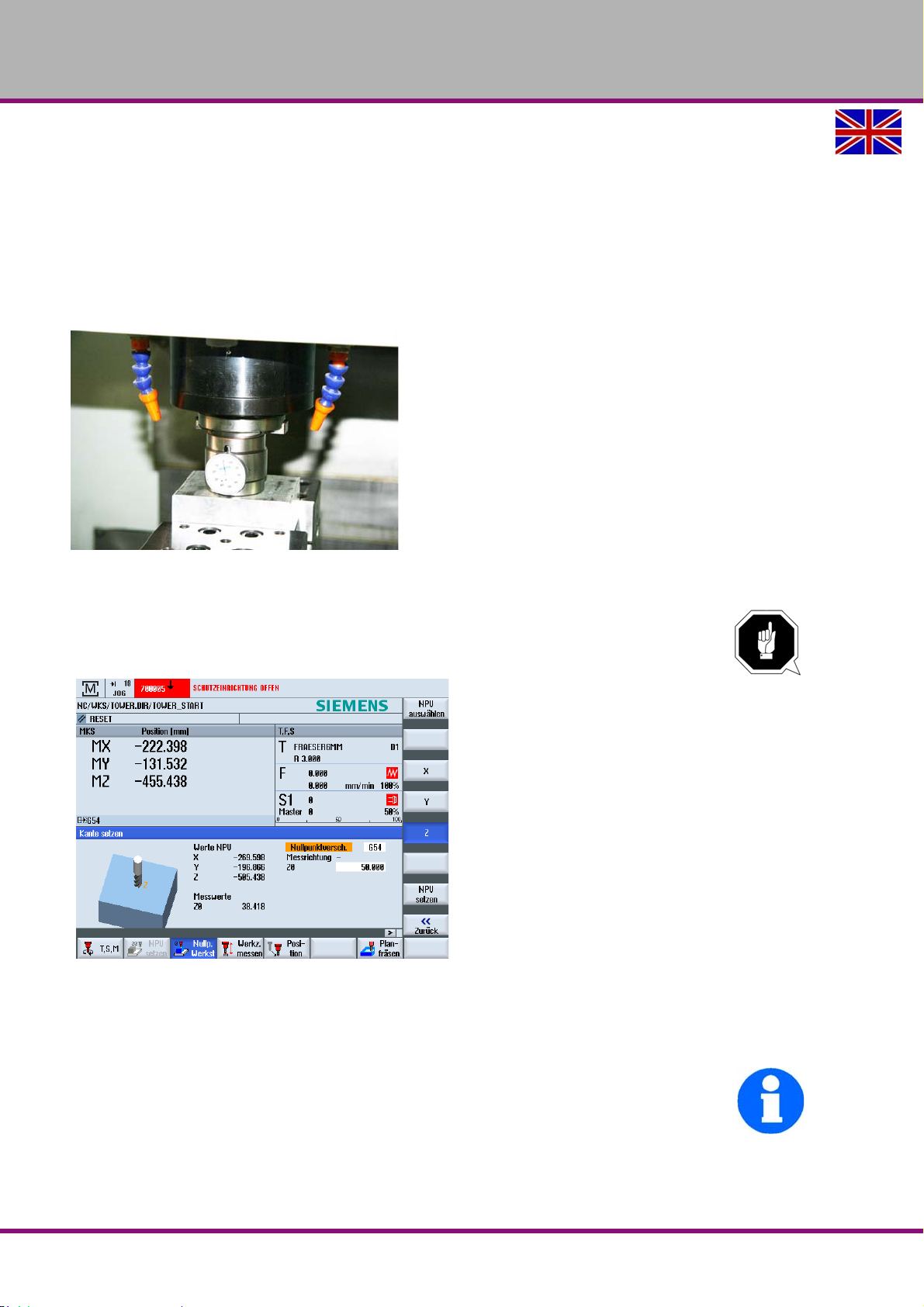
OPTIMUM
MASCHINEN - GERMANY
Img.6-6: Set workpiece datum X axis resp. Y axis
Press the button "Zero offset".
Press the key "Set NPU" after determining the workpiece datum of the corresponding axis.
Measuring the Z axis by means of a pressure sensor
Change a tool with a length of "0" listed in the tool list
Travel the spindle (Z axis) to the pressure sensor (by means of the handwheel) until the
indicated value is "0".
Img.6-7: Workpiece datum Z axis with pressure sensor
Enter for Z0 = 50mm . This is the height of the measuring probe.
NOTE!
Make sure to always enter positive values.
Img.6-8: Determining workpiece zero point Z axis
Confirm the setting by pressing the button "Set NPU".
6.8.2 Setting resp. measuring tool
INFORMATION
For the setup operation (JOG operation) the sliding door for the separating protective
equipment can be opened.
Also refer to chapter 4 "Setup machine" in the operating instructions for "SINUMERIK 828 D".
Measuring a milling cutter by means of a pressure sensor
Change the tool in the spindle.
F150GB
Version 1.1.6 dated 2014-10-16Page 78 Original operating instructions
Operation
Page 79
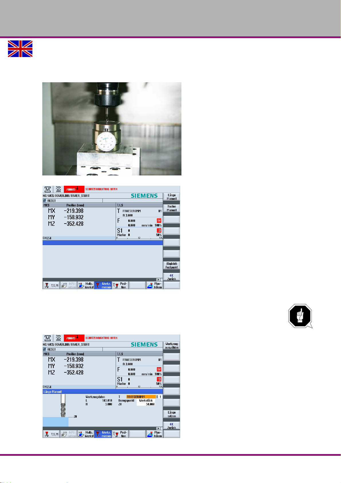
OPTIMUM
MASCHINEN - GERMANY
Actuate the button "Measure tool".
Travel the spindle (Z axis) to the pressure sensor (by means of the handwheel) until the
indicated value is "0".
Measuring tool
Img.6-9: Measuring tool
Press the button "Set length".
NOTE!
Make sure that the display for active tool "T" is equipped with the correct tool. The workpiece is
the reference point!
Operation
F150 GB
Version 1.1.6 dated 2014-10-16 Page 79Original operating instructions
Page 80

OPTIMUM
MASCHINEN - GERMANY
6.9 Operational modes
Manually controlled operation
The manually controlled operation is allowed in the operating mode "JOG" and in the operating
mode "MDA". Refer to chapter 5 "Manually controlled operation" of the instructions "SINUMERIK 828 D".
Automatic mode
Refer to chapter 6 "Automatic mode" of the instructions "SINUMERIK 828 D".
6.10 Programming
For further working steps please proceed as described in the operating instructions "Part programming, system, programming and cycles“ for "SINUMERIK 828 D".
Manual resp. part programming:
For this kind of programming, the programs must be created manually and entered in the control. The direct programming in the DIN-Code is a complex method which requires lots of
skills.Nowadays this task is mostly taken over by CAD/CAM systems which directly create an
operating program using a graphical user interface.
Automatic programming:
By means of the CAD/CAM program (for instance a 3D-CAD program including downstream
co-processor) construction data are transmitted (semi-)automatically to an executable program. For this kind of programming a 3D model is designed using a PC. By means of an operating sequence which is predefined by the user the motion-sequence of the machine are being
calculated. These programs are accessing the tool data base which includes all tool parameters
(speed, feed, diameter, etc.). Due to this systematic program structure the user is able to create
complete programs within shortest time without having any knowledge of the individual program
commands and its syntax.
As aid for training and operation we recommend to use the software SinuTrain made by
Siemens.
SinuTrain is the ideal software supplement for the CNC milling machine F150 made by OPTIMUM.
This training software supports the rapid training for the operation of the control Sinumerik
SINUMERIK 828 D. Employees having little CNC experience can learn the basics of the DIN
programming by using SinuTrain and are finally able to write and test programs using SINUMERIK 828 D-cycles.
Please find SinuTrain and further information on the website of Siemens.
6.11 Start program
If necessary, open the setting screw for the coolant / lubricant supply on the spindle head
before starting the program. It is only allowed to change the dosing during the setup operation.
If necessary the cooling lubricant supply is switched on via your CNC-program.
WARNING!
Never change the dosing of the cooling lubricant supply and never seize into the machine when
a program is running.
F150GB
Version 1.1.6 dated 2014-10-16Page 80 Original operating instructions
Operation
Page 81
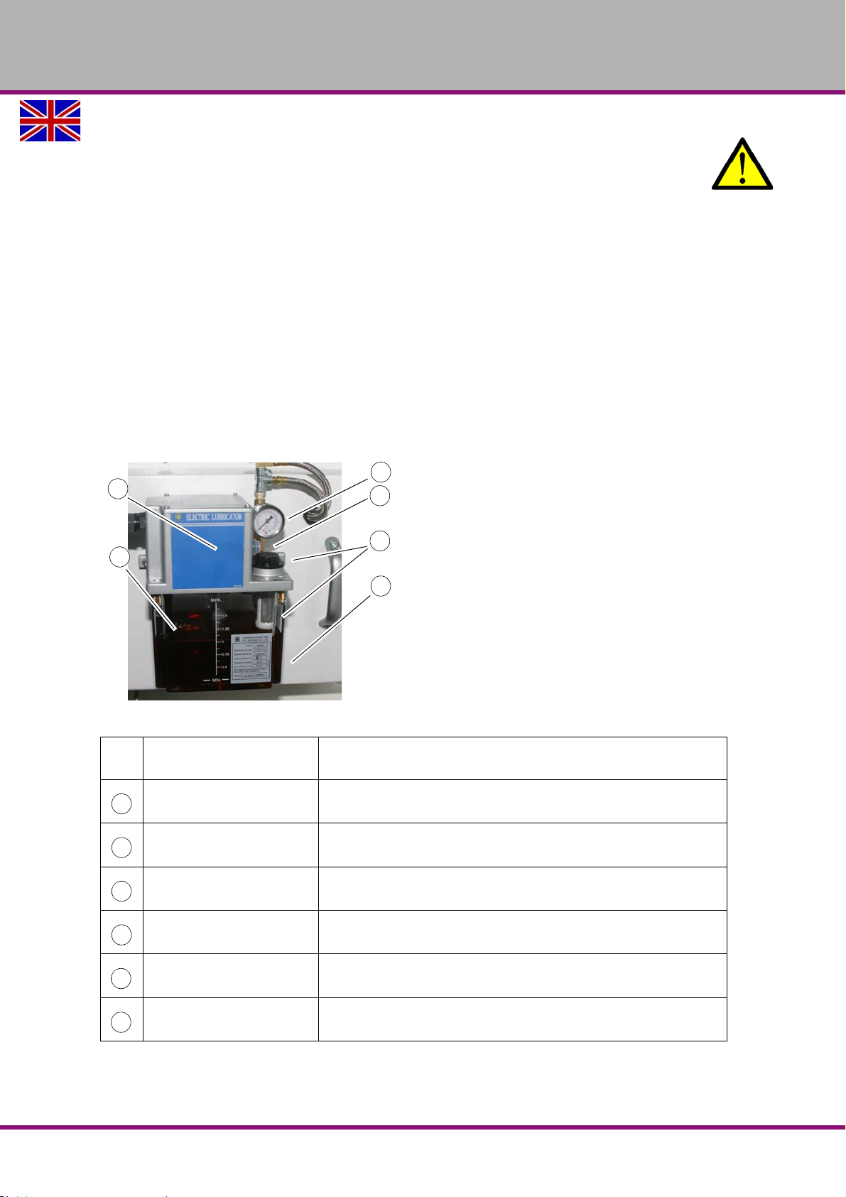
OPTIMUM
1
4
5
3
2
6
1
2
345
6
MASCHINEN - GERMANY
CAUTION!
Before starting the programs you have to close the sliding door of the separating
protective equipment.
Completely close the separating protective equipment.
Change over to the mode "AUTO/MDA"
For further working steps please proceed as described in the chapter of the
control"SINUMERIK 828 D".
6.12 Operating the central lubrication system
The CNC machine is equipped with a central lubrication system. This option is used to "manually" set the supply of the oil quantity. During operation the supply positions are automatically
supplied with oil in regular intervals using a time measuring instrument.
The lubricating system is used to maintain an oil film on the slideways, the bearings, the ledges
and the ball screws and to reduce their wear.
In case of a failure or a fault in the central lubricating system a stick-slip effect may occur. This
effect describes the jerky sliding of solids moving opposite one another. For instance: creaking
doors and rattling windscreen wipers.
Img.6-10: Operating elements of the central lubrication system
Pos.
No
Push button (function key) Lubricating cycle activated
Meaning Description
Pump Manually conveys the machine oil
Oil tank Includes the oil quantity
Oil filler hole / oil filter
Float switch Recognising the oil level in the tank
Manometer
It is possible to fill in machine oil via the filler hole resp. the machine
oil is filtered via the oil filter.
Measuring device to collect and display the physical pressure of the
medium
Operation
Version 1.1.6 dated 2014-10-16 Page 81Original operating instructions
F150 GB
Page 82
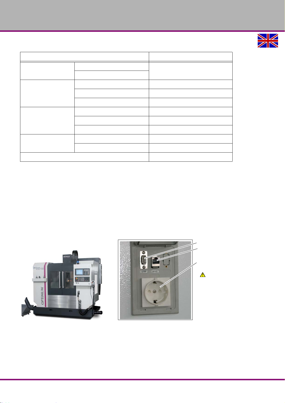
OPTIMUM
USB interface
Network connection
Socket for current collection
(230V) e.g. for a notebook
Warning!
Do not use any devices which
require more than 2 A current!
MASCHINEN - GERMANY
Designation Specification
Timer
Motor
Pump
Storage reservoir
Oil viscosity 32-68 cSt@40°C
Act Time
controlled by the timer
Interval Time
Current consumption 2.5 A
Phases 1
Power 12 W
max. delivery flow 130 cc/min
max. delivery pressure 15 kgf/cm²
Diameter pressure joint 6mm
Capacity 2.5 litres
Material Resin
6.13 Data interfaces and current collection
When connecting data interfaces make sure that the data cable runs to the interface of the controlwithin shortest possible distance. The cable routing can be conducted along the measuring
system lines. However the cable in the switch cabinet must never be routed nearby the drive
apparatuses of the NC axis or the frequency converter itself. Errors occur during data transfer
due to electromagnetic radiation (EMC-problems).
The control is equipped with the following data interfaces. They are located laterally on the control panel of the CNC machine:
RJ45 plug- in connection
USB connection
Power connection (socket for current supply (230V) e.g. for a notebook)
Img.6-11: Data interfaces and current collection
F150GB
Operation
Version 1.1.6 dated 2014-10-16Page 82 Original operating instructions
Page 83

OPTIMUM
MASCHINEN - GERMANY
6.14 Executing from an external position
Excerpt from the manual of the operating instructions for "SINUMERIK 828 D".
12.13 EXTCALL
It is possible to access the files on the local drive , USB data carrier or networks using the
command EXTCALL .
The programmer can determine the source directory by means of the setting date
SD$SC42700 EXT_PROG_PATH and file name for the sub-program to be reloaded using thecommand EXTCALL.
Edge conditions
Observe the following edge conditions for EXTCALL prompts:
It is only possible to call files with the identification MPF or SPF via EXTCALL from a net-
work.
The files and paths have to correspond to the NCK nomenclature (max. 25 characters for
the name, 3 characters for the identification).
A program on a network can be found using the command EXTCALL if
- the search path refers to the network or to a directory SD $SC42700 EXT_PROG_PATH.
The program has to be directly filed, no sub-directories are browsed.
- Without SD $SC42700: in the EXTCALL prompt the program is directly indicated and
alsolocated there - via a fully qualified path, which can also refer to the network driv .
Examples for EXTCALL prompts
The setting data can be used to perform a target search for the program.
Prompt USB drive to TCU (USB storage device on the interface X203), whenSD42700 is
empty: e.g. EXTCALL "//TCU/TCU1 /X203 ,1/TEST.SPF"
-Or Prompt USB drive to TCU (USB storage device on the interface X203), whenSD42700
includes "//TCU/TCU1 /X203 ,1/TEST.SPF" EXTCALL "TEST.SPF"
Prompt for USB Front connection (USB-FlashDrive), if SD $SC 42700 is empty : e.g. EXT-
CALL"//ACTTCU/FRONT,1/TEST.SPF"
-Or Prompt of USB Front connection (USB-FlashDrive), when SD42700 "//ACTTCU/
FRONT,1" is included: EXTCALL "TEST.SPF"
Operation
Version 1.1.6 dated 2014-10-16 Page 83Original operating instructions
F150 GB
Page 84
OPTIMUM
MASCHINEN - GERMANY
7 M - code list, M functions
The following code list are the manufacturer-specific M-codes of the machine.
Some M-codes are provided for an optional equipment of the CNC machine and are only activated if
the CNC machine is equipped with this equipment.
S / O S = Standard O = Option
No. Function S / O
M00 Programmed stop S
M01 Optional Stop S
M02 End of program S
M03 Starting the milling spindle in positive
direction (clockwise)
M04 Starting the milling spindle in nega-
tive direction (anti-clockwise)
M05 Stopping the milling spindle S
M06 Automatic tool change S
M07 Coolant through spindle ON O
M08 Cooling lubricant pump ON S
M09 Cooling lubricant pump OFF
M07/M12/M50 OFF
M10 The 4th axis clamp S
M11 The 4th axis unclamp S
M12 Chip wash down coolant 1 ON O
M13
M14
M15 Open front door O
M16 Close front door O
M17 End of subroutine S
M18
M19 Spindle stop in defined limit position
(0 degree)
M20 Program end with resetting (Reset)
M21
M22
M23
M24 Chip Conveyor CW ON O
M25 Chip Conveyor CW OFF O
M26 Workpiece clamp S
S
S
S
S
S / O S = Standard O = Option
No. Function S / O
M27 Workpiece unclamp S
M28
M29
M30 Program end & Rewind S
M31 Opening a lock
M32
M33
M34
M35
M36
M37
M38
M39
M40 Automatic Spindle Gear Change
( by S-Code )
M41 Spindle Gear Change to Stage 1 S
M42 Spindle Gear Change to Stage 2 S
M43 Spindle Gear Change to Stage 3 S
M44 Spindle Gear Change to Stage 4 S
M45 Spindle Gear Change to Stage 5 S
M46
M47
M48
M49
M50 Oil Mist / External Air Blower O
M51
M52
M53
M54
M55
M56
M57
M58
M59
S
F150 | F310 | F410GB
M - code list, M functions
Version 1.1.6 dated 2014-10-16Page 84 Original operating instructions
Page 85
OPTIMUM
MASCHINEN - GERMANY
S / O S = Standard O = Option
No. Function S / O
M60 Workpiece replacement
M61
M62
M63
M64
M65
M66
M67
M68
M69
M70
M71 Spindle position control on S
M72
M73
M74
M75
M76
M77
M78
M79
S / O S = Standard O = Option
No. Function S / O
M94
M95
M96
M97
M98
M99
7.1 G function according to PAL
G0 Travelling in rapid traverse
G1 Linear interpolation during process
G2 Circular interpolation clockwise
G3 Circular interpolation anti-clockwise
G4 Retention period
G9 Accurate stop
G10 Travelling in rapid feed in polar coordinates
G11 Linear interpolation with polar coordinates
G12 Circular interpolation clockwise with polar
coordinates
G13 Circular interpolation anti-clockwise with
polar coordinates
G45 Linear tangential travelling on a contour
G46 Linear tangential travelling off the contour
G64 Accurate stop off
M80 M81 / I11.2 (183) for finish O
M81 for M80 finish O
M82 M83 / I11.3 (184) for finish O
M83 for M82 finish O
M84 M85 / I11.4 (185) for finish O
M85 for M84 finish O
M86 M87 / I11.5 (186) for finish O
M87 for M86 finish O
M88 M89 / I11.6 (187) for finish O
M89 for M88 finish O
M90 M91 / I11.7 (188) for finish O
M91 for M90 finish O
M92
M93
M - code list, M functions
F150 | F310 | F410 GB
Version 1.1.6 dated 2014-10-16 Page 85Original operating instructions
Page 86

OPTIMUM
MASCHINEN - GERMANY
8 Notes, messages and error messages
All messages and alarms are displayed in plain text on the operator panel. The alarm text contains the date, time and a suitable symbol for the cancel criterion.
Alarms and messages are displayed separately according to the following criteria:
Alarms and messages in the part program.
Alarms and messages from the plc and alarms and messages that concern the machine.
The following notes, messages and error messages are the vendor-specific messages of the
machine.
Several messages and error messages are an optional feature of the CNC machine and provided only active when the CNC machine has these features.
Number Message description
700000 Emergency stop button pressed, release it and press reset on MCP
Possible cause
700008 Feed not enabled on machine control panel !
Possible cause
and remedy
700009 Waiting for spindle up to speed. . .
700010 plc alarm DB1600.DBX1.2
700011 Automatic power off active, servo off!
Effect • Drive off!
700016 Hydraulic pump overloaded.
Possible cause
700017 Hydraulic pressure not reached.
Possible cause
• Unlock the Emergency stop button and press reset on the machine control panel (MCP).
• Emergency stop button defect and gives an erroneous signal.
• Enable feed on machine control panel.
Motor protection switch of the hydraulic pump is faulty.
Motor protection switch setting faulty.
Hydraulic pump is sucking air.
Clamping pressure / working pressure set too high.
Hydraulic pump or drive motor defective.
• Subsequent alarm 700 016
• Pressure too low
• Pressure switch is defective on the hydraulic unit.
700019 T code error.
700020 Tool change error.
700021 Tool change position data loading error.
700022 Axis %D PLC positioning error.
700023 Spindle zero position, check sensor not ON.
700024 Tool clamp / unclamp error.
700025 Arm rotate error.
700026 Tool pocket up/down error.
700027 Tool magazine position error.
F150GB
Notes, messages and error messages
Version 1.1.6 dated 2014-10-16Page 86 Original operating instructions
Page 87
Number Message description
700028 Tool data error
OPTIMUM
MASCHINEN - GERMANY
possible rem-
edy
700030 Machine control panel error (MCP)
possible rem-
edy
700031 Magazine in / out error.
700032 Waiting for SINAMICS ready. . .
700033 Operator door safety check, open door and close it again.
Cause and
solution
• Check tool table!
Check type / MD / connection.
Safety door needs test, open then close it again.
• Press the push button "door open - close"
• Open the door and close the door again completely.
• Press after closing the door the push button "RESET.
"Switching on the CNC machine“ on page 73
700040 Waiting for tool clamped.
700041 Waiting for tool unclamped.
700044 Tool probe Low battery
700046 Tool probe error
700048 Coolant motor overloaded
• Motor protection switch of the coolant pump is faulty.
Possible cause
and remedy
Possible cause
and remedy
700050 Coolant level low.
Possible cause
and remedy
700051 CTS coolant motor overloaded.
700052 CTS recycle motor overloaded.
700053 CTS sub-tank level low, no coolant suction.
700055 CTS inlet filter clogged.
700056 CTS sub-tank level high.
700060 Spindle oil cooler alarm !
700064 Waiting for tool change . . .
700075 Waiting for gear changing. . .
• Motor protection switch setting faulty.
• Coolant pump is sucking air.
• Shut-off cock is closed.
• Pump or drive motor defective.
• Contactor of the coolant motor signals an incorrect switch status.
• Fill up coolant
• Float switch in the central oil lubrication
700080 Asup1 initialise error, check PLCASUP1.SPF
700081 Asup2 initialise error, check PLCASUP2.SPF
700082 Asup1 execution error.
Notes, messages and error messages
Version 1.1.6 dated 2014-10-16 Page 87Original operating instructions
F150 GB
Page 88

OPTIMUM
MASCHINEN - GERMANY
Number Message description
700083 Asup2 execution error.
700084 Magazine rotation error.
700085 Magazine to home error.
700086 Magazine motor overloaded
700087 Arm motor overloaded
700088 Unclamp tool manually to confirm empty spindle for safety.
Possible cause
and remedy
700089 Magazine gate manual operation active.
700090 Magazine manual rotation active.
700091 Manual tool unclamp active.
700092 Tool pocket manual up/down active.
700093 Arm manual rotation active.
700094 Safety door not locked,NC start disabled.
Possible cause
and remedy
700095
700104 Magazine manual in/out active.
700105 Handwheel 1 is active. (External)
700106 Handwheel 1 is active. (HMI)
700107 Handwheel 2 is active. (HMI)
700108 Door not closed to the magazine
• First insertign of a tool
•
"First insertion of a tool“ on page 74
• Limit switch with door lock outputs a signal that the safety door is not locked.
• Safety door not fully closed and locked.
*** Service mode ***
"Quit the ATC-Service mode“ on page 76
700109 Right-hand door is not closed
700110 Left door is not closed
700128 Z axis is not referenced, positioning by PLC not possible.
700136 Tool changer not at home, Z axis inhibited
700137 Tool changer at spindle switch error, Z axis inhibited
700146 Spindle cooler unit not ready !
700152 Spindle not enabled ?
Possible cause
and remedy
700153 Spindle hold.
700154 Tool not clamped, spindle stop
700155 M00/M01 Spindle stop.
700156 Tool changer not at home, Spindle stop.
F150GB
• Enable spindle on machine control panel.
Notes, messages and error messages
Version 1.1.6 dated 2014-10-16Page 88 Original operating instructions
Page 89
Number Message description
700157 Spindle controlled by PLC
700158 Change phases on main electrical connection
700159 PLC-Alarm (DB1600.DBX19.7)
700160 Tool clamp/unclamp sensor fault.
700161 Lubrication time setting error,check setting data
700162 Lubrication level low.
700163 Lubrication pressure not reached.
700164 Chip conveyor motor overloaded.
700165 Chip conveyor motor contactor feedback error.
OPTIMUM
MASCHINEN - GERMANY
Possible cause
and remedy
700166 Chip auger motor overloaded.
700167 Chip auger motor contactor feedback error.
Possible cause
and remedy
700168 Magazine counter too fast(%Fsecond), position value is not valid.
700169 Magazine stop but not in position, position value is not valid.
700170 Magazine needs to go to reference.
700171 Magazine rotation control mode not in auto,tool change interrupted.
700172 Magazine location for return tool is not free, tool change not possible.
700173 Chip Wash motor overloaded
700176 Arm position sensor fault.
700179 plc alarm DB1600.DBX22.3
700180 Air pressure low.
• Contactor of the conveyor motor signals an incorrect switch status.
• Drive motor connector for chip conveyor is not connected ?
• Contactor of the conveyor motor signals an incorrect switch status.
• Drive motor connector for chip conveyor is not connected ?
• Compressed air switch in the near of the compressed air maintenance unit report a low pres-
Possible cause
and remedy
700181 Coolant system low.
700186 Automatic / manual switch must be switched
700190 CTS coolant tank is full
700202 Safety Integrated Test Stop Request
700203 Feed override =0
700205 Chip conveyor disabled, close door/release emergency stop.
700206 Chip conveyor disabled, close door/release emergency stop.
Notes, messages and error messages
Version 1.1.6 dated 2014-10-16 Page 89Original operating instructions
sure.
•
"Compressed air supply“ on page 21
"Drain compressed air service unit“ on page 102
•
• "Connection compressed air supply“ on page 45
F150 GB
Page 90

OPTIMUM
MASCHINEN - GERMANY
Number Message description
700207 Manual tool unclamp disabled, stop spindle and program first.
700210 Magazine referencing . . .
700211 Magazine jog disabled, close door/reset program.
700212 Safety door operation disabled, stop program/spindle first!
700213 Tool pocket manual up/down disabled, close door/stop program,check magazine and arm.
700214 Arm rotate manual disabled, stop program and jog pocket down first.
700215 Magazine in/out disabled, close door/reset program
700216 ALM status: EP is ON
700217 ALM status: OFF1 is ON
700218 ALM status: OFF3 is ON
700220 ASUP1 initializing .
700221 ASUP2 initializing .
700222 Spindle clamp without tool, speed limited.
700224 Checking position . . .
700225 Unclamp spindle to continue . . .
700226 Clamp spindle to continue .
700227 Arm reverse from home position is not allowed.
700228 Safety Integrated Safe Operational Stop Active
700229 Safety Integrated Safe Stop 1 Active (ESTOP)
700230 Please go to reference !
700231 Safety Integrated Please Close Door for Test
700232 Maintenance Task 1 Alarm
700233 Maintenance Task 1 Message
700234 Maintenance Task 2 Alarm
700235 Maintenance Task 2 Message
700236 Maintenance Task 3 Alarm
700237 Maintenance Task 3 Message
700238 Maintenance Task 4 Alarm
700239 Maintenance Task 4 Message
700240 Maintenance Task 5 Alarm
700241 Maintenance Task 5 Message
700242 Maintenance Task 6 Alarm
700243 Maintenance Task 6 Message
700244 Maintenance Task 7 Alarm
700245 Maintenance Task 7 Message
F150GB
Notes, messages and error messages
Version 1.1.6 dated 2014-10-16Page 90 Original operating instructions
Page 91

Number Message description
700246 Maintenance Task 8 Alarm
700247 Maintenance Task 8 Message
OPTIMUM
MASCHINEN - GERMANY
Notes, messages and error messages
Version 1.1.6 dated 2014-10-16 Page 91Original operating instructions
F150 GB
Page 92

OPTIMUM
MASCHINEN - GERMANY
9 SINUMERIK 828 D
The instructions for the use of the SIEMENS control "SINUMERIK 828 D" is composed of the
following items which are listed at the end of these operating instructions or separately attached
to the machine.
Operating instructions
Edition: 06/2009
Document number: 6FC5398-7CP20-0AA0
Programming manual production planning
Edition: 06/2009
Document number: 6FC5398-2BP20-0AA0
Programming manual milling
Edition: 06/2009
Document number: 6FC5398-7BP10-1AA0
SinuTrain "Simple milling using ShopMill"
Edition: 06/2009
Document number: 6FC5095-0AB50-1AP0
Diagnosis manual
Edition: 06/2009
Document number: 6FC5398-8BP10-0AA0
For any questions regarding the CNC control, please contact:
Siemens AG, A&D techsupport
Phone (+49) 0180 50 50 222
mailto: [email protected]
Siemens AG Hotline, Helpline
Phone (+49) 0180 50 50 111
F150GB
Version 1.1.6 dated 2014-10-16Page 92 Original operating instructions
SINUMERIK 828 D
Page 93
10 Maintenance
MAINTENANCE
Inspection
Maintenance
Repair
Measuring
Cleaning Mending
Testing Cleaning Replacing
Conserving
Lubricating
Completing
Replacing
Readjusting
Adjusting
In this chapter you will find important information about
Inspection
Maintenance
Repair
of the CNC machine
The diagram below shows you which tasks belongs to which term.
OPTIMUM
MASCHINEN - GERMANY
Img.10-1: Maintenance – Definition according to DIN 31 051
ATTENTION!
Properly performed regular maintenance is an essential prerequisite for
operational safety,
failure-free operation,
long service life of the CNC machine and
the quality of the products which you manufacture.
Installations and equipment from other manufacturers must also be in good order and condition.
10.1 Operating material
10.1.1 Machine lubricants
Only use appropriate lubricants which guarantee a safe operation of the machine.
Recommended lubricant class: ISO V668
Recommended lubricant: guideway oil Mobil Vactra (Oil No. 2) 2)
10.1.2 Cooling lubricants
In order to avoid interferences during operation the water-mixed cooling lubricant and the slideway oil or grease need to be compatible.
Read also:
INFORMATION
The CNC milling machine is lacquered with a one-component paint. Observe this fact when
selecting your cooling lubricant.
"Cooling lubricants and tanks“ on page 108
Maintenance
Version 1.1.6 dated 2014-10-16 Page 93Original operating instructions
F150 GB
Page 94
OPTIMUM
MASCHINEN - GERMANY
The company Optimum Maschinen Germany GmbH does not assume any guarantee on subsequent damages due to unsuitable cooling lubricants.
The flashpoint of the emulsion must be higher than 140°C.
When using cooling lubricants that cannot be mixed with water (oil content > 15%) with a flashpoint, ignitable aerosol air mixtures might develop. There is a potential danger of explosion.
ATTENTION!
Only the correct selection of an appropriate combination of cooling lubricants and
slideway oils as well as the proper care and maintenance of the cooling lubricant can
ensure that no problems such as stick-slip effects or deposits are resulting.
The selection of cooling lubricants and slideway oils, lubricating oils or greases as well as their
care are being determined by the machine operator or operating company.
Therefore, Optimum Maschinen Germany GmbH cannot be held liable for machine damages
caused by unsuitable coolants and lubricants as well as by inadequate maintenance and servicing of the coolant. In case of problems with the cooling lubricant and the slideway oil or grease,
please contact your supplier for mineral oils.
ATTENTION!
Cooling lubricants and oils for the mechanic and pneumatic system of the machine have
to be adjusted referring the water added initially, the cooling lubricant emulsion and the
machining task.
We would like to ask you to have the following machine-related properties of the cooling lubricant confirmed in writing by the manufacturer of the cooling lubricant.
The products must comply with the provisions of the current statutory regulations and the
employers liability insurance association.
Request documentation for the products such as the product description VKIS and EC
safety data sheet from the cooling lubricants manufacturer. The EC safety data sheet gives
you information about the water-hazard class.
They need to be environmentally friendly and workplace-friendly. Thus, they need to be free of
nitrite, PCB, chlorine and nitrosinable diethanolamin (DEA), according to TRGS 611.
The manufacturer should be able to submit a certificate concerning skin-tolerance.
The mineral content according to DIN 51417 should be at least 40% concentrate.
If possible, it should be universally applicable for all chippings and materials.
Long service life of the emulsion e.g. long-term stable and resistant to bacteria.
Safe corrosion protection according to DIN 51360/2.
Re-emulsifiable and non-adhesive according to VKIS sheet 9: Sticking and residue behav-
iour.
It should not attack the varnish of the machine according to VDI 3035.
It should not attack any machine elements (metals, elastomeres).
Low foaming behaviour of the emulsion.
It should be as finely dispersed as possible in order to avoid clogging in the needle slot
screen.
10.2 Safety
WARNING!
The consequences of incorrect maintenance and repair work may include:
Severe injuries of persons working on the CNC machine,
damage to the CNC machine.
Only qualified personnel should carry out maintenance and repair work on the circular
CNC machine.
F150GB
Version 1.1.6 dated 2014-10-16Page 94 Original operating instructions
Maintenance
Page 95

OPTIMUM
MASCHINEN - GERMANY
Validation
Check and maintain all safety-relevant stop, control and measuring devices (validation).
Documentation
Record all tests and works in a operator's log resp. log book.
10.2.1 Preparation
WARNING!
Only carry out work on the CNC machine, if the main switch is switched off and secured
against restarting by means of a padlock.
"Disconnecting and securing the CNC machine“ on page 18
Attach a warning sign.
10.2.2 Restarting
Before restarting, run a safety check.
"Safety check“ on page 16
WARNING!
Before starting the CNC machine, you must check that there is no danger for persons
and that the CNC machine is not damaged.
It is recommended to clean the electrical cabinet every 1000 operating hours.
10.3 Repair
10.3.1 Customer service technician
For any repair work request the assistance of an authorised customer service technician. Contact your specialist dealer if you do not have customer service's information or contact Stürmer
Maschinen GmbH in Germany who can provide you with a specialist dealer's contact information. Optionally, the
Stürmer Maschinen GmbH
Dr.-Robert-Pfleger-Str. 26
D- 96103 Hallstadt
can provide a customer service technician, however, the request for a customer service technician can only be made via your specialist dealer.
If the repairs are carried out by qualified technical personnel, they must follow the indications
given in these operating instructions.
The company Optimum Maschinen Germany GmbH does not take any liability nor does it guarantee against damage and operating malfunctions resulting from failure to observe this operating instructions.
For repairs only use
faultless and suitable tools,
original parts or parts from series expressly authorized by Optimum Maschinen Germany
GmbH.
Maintenance
Version 1.1.6 dated 2014-10-16 Page 95Original operating instructions
F150 GB
Page 96

OPTIMUM
MASCHINEN - GERMANY
10.4 Inspection and maintenance
The type and level of wear depends to a large extent on the individual usage and operating
conditions. Any indicated intervals therefore are only valid for the corresponding approved conditions.
Interval Where? What? How?
"Safety check“ on page 16
Start of work, after each
maintenance or repair work
CNC milling machine
Sight window
Cleaning
Draining
Clean the sight windows made of polycarbonate
using a suitable cleaning agent.
"Drain compressed air service unit“ on page
102
Check
Start of work, Daily
after every maintenance or repair work
Compressed air supply
Lubricant tank
Oil collecting tank
Filling level control
Slideway oil
Empty
Manual
Check the quantity and refill the lubricant tank of
the central lubrication system. See also
ing lubricants“ on page 93
Check the oil level in the oil collecting gutter.
Empty the oil collecting tank.
"Cool-
F150GB
Version 1.1.6 dated 2014-10-16Page 96 Original operating instructions
Page 97

OPTIMUM
MASCHINEN - GERMANY
Interval Where? What? How?
"Data backup on the control“ on page 49
Every week
Oil all bare steel surfaces. Use an acid-free oil,
Every week
Every week
every week
Oiling
Lubricating
CNC- milling machine
Status control of fill-
Cooling
Cooling
ing level
lubricant tank
pH value measuring
lubricant
e.g. weapon oil or motor oil.
Press the push-button of the central lubricating
system.
Check for liquid level, concentration, pH value,
bacteria and fungal decay.
"Cooling lubricants and tanks“ on page 108
Check the ph-value. If required, replace the cooling lubricant.
"Inspection plan for water-mixed cooling lubri-
cants“ on page 109
Check
Every week
Every month
Annually
Filling level control
Drip feed lubricator
Compressed air cylinder
Check
Readjusting
Gear belt
Clutch
Replacing
Spindle head
Check
Readjusting
Air purge
Check
Replacing
Check the liquid level and refill if required.
Check the drive belt on wear and excessive clearance.
If required, readjust the gear belt and/or replace it.
Check the function of the air purge.
If necessary re-adjust the amount of air.
"Air purge“ on page 102
Check if coupling is worn and check coupling
slack.
If necessary, replace the coupling.
Coupling Drive Z-, Y-, X-axis
Version 1.1.6 dated 2014-10-16 Page 97Original operating instructions
F150 GB
Page 98

OPTIMUM
MASCHINEN - GERMANY
Interval Where? What? How?
Check
Replacing
the slides
Wipers on
Cleaning "Cleaning electrical cabinet“ on page 101
Every 1000
operating hours
Every six months
Switch cabinet
Inspection Connections on the servo motors.
Servo motors
Check the tool
change function.
Positioning
Tool changer
Check the wipers on the slides.
Replace if damaged immediately.
By manual changing
"Manual operation of the tool changer“ on
page 76
Check
Empirical value of the
As required
Annually
operator
60 months
Cleaning
Chip collection tray
Check
Readjusting
Chip conveyor
Cleaning
Chip collection tray
Replacing the sight
window
Protective covers
Clean the chip collection tray of the cooling lubricant equipment.
Check, readjust the scraper of the screw conveyor
"Späneförderer - Chip convejor“ on page 135
Position No 10.
Clean the precoat filter of the chip tray
"Maschinengehäuse - Machine housing“ on
page 134 Position No 49.
"Cleaning and replacing of the polycarbonate
windows“ on page 100
F150GB
Version 1.1.6 dated 2014-10-16Page 98 Original operating instructions
Page 99

OPTIMUM
MASCHINEN - GERMANY
Interval Where? What? How?
"Obligations of the operating company“ on
page 12
Electrical inspection
"Electrical system“ on page 20
"Validation“ on page 95
based on operator's
empirical values
in accordance with German DGUV (BGV A3)
Electrical system
Check
Version 1.1.6 dated 2014-10-16 Page 99Original operating instructions
F150 GB
Page 100
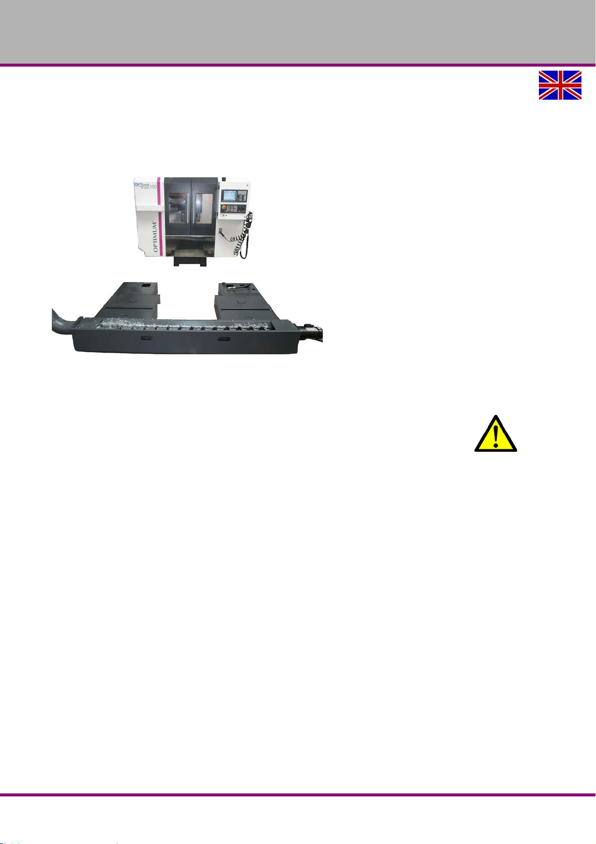
OPTIMUM
MASCHINEN - GERMANY
10.4.1 Disassembly of the cooling lubricant tank
The coolant / lubricant tank can be completely extracted from below the CNC machine for
cleaning purposes. In order to allow this, the following working steps are required.
Disassemble the cooling pump and the hoses.
"Coolant / lubricant pumps“ on page 35
Img.10-2: Cooling lubricant tank
10.4.2 Cleaning and replacing of the polycarbonate windows
WARNING!
The polycarbonate viewing window are part of the safety device on your CNC machine.
Damaged, scratched or even broken polycarbonate windows must be replaced
immediately.
A soft cloth should be used to clean the machine safety glass. Have been tested and approved
by us:
Hahnerol glass cleaner (Hahnerol), Sidolin Streak Free (Henkel), Active Window Cleaner (Neumann).
We recommend to replace the polycarbonate viewing window of the door after 60 months of
commissioning of the CNC machine.
In the following cases, an immediate replacement is strongly recommended:
plastic deformation (distortion) by previous impact stress,
cracks,
Damage to the edge seal,
immersion of cooling agent in the composite structure,
destroyed or damaged window (coating) on the workspace or operator position.
F150GB
Version 1.1.6 dated 2014-10-16Page 100 Original operating instructions
 Loading...