

Page 1
OPTIMUM
Item no. 3049050
MASCHINEN - GERMANY
Operating Manual
Version 1.0
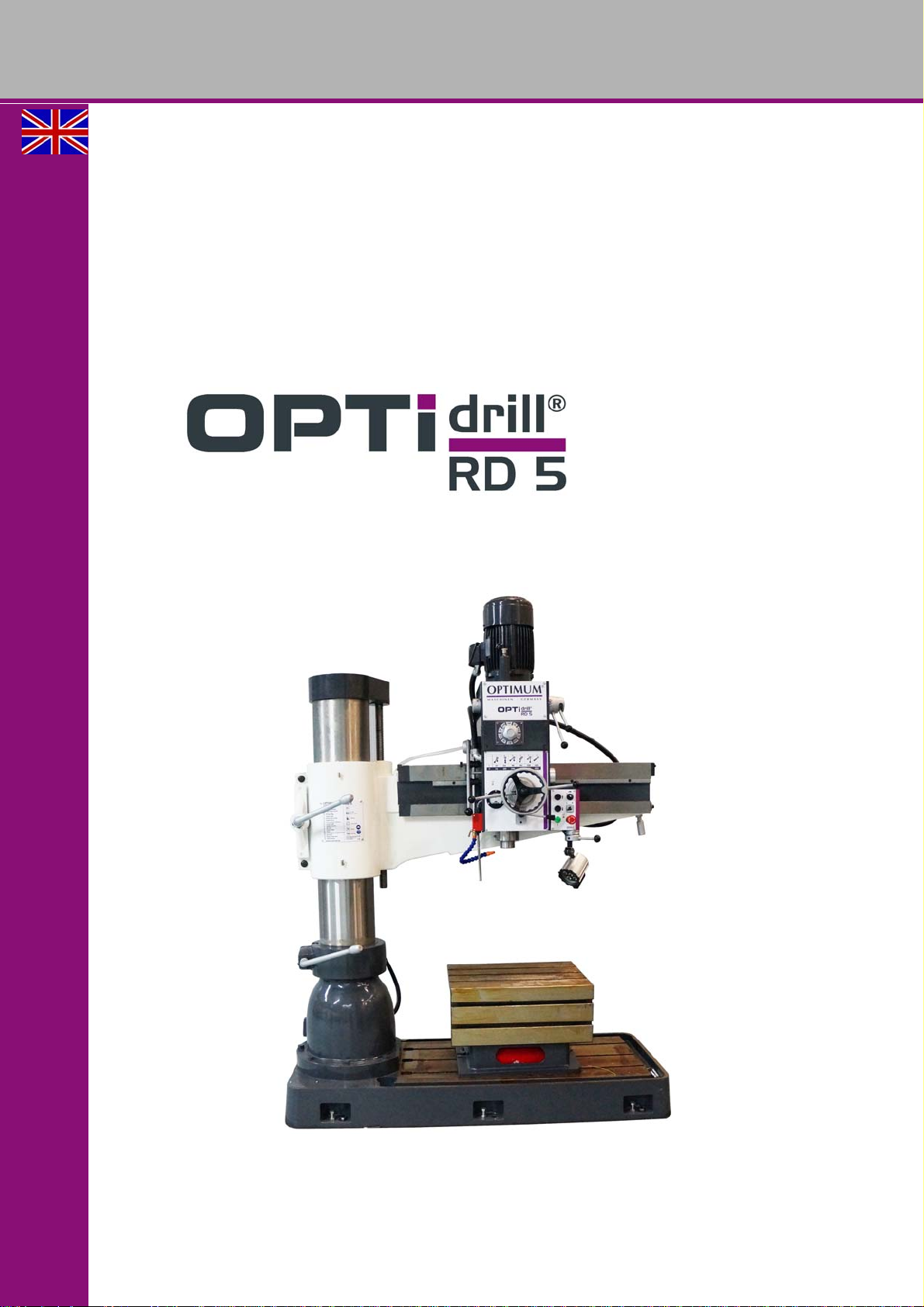
Radial drilling machine
GB
Page 2

OPTIMUM
MASCHINEN - GERMANY
Table of contents
1 Safety
1.1 Type plate.................................................................................................................................................6
1.2 Safety instructions (warning notes)...........................................................................................................7
1.2.1 Classification of hazards...........................................................................................................................7
1.2.2 Other pictograms ......................................................................................................................................7
1.3 Intended use .............................................................................................................................................9
1.4 Reasonably foreseeable misuse...............................................................................................................9
1.4.1 Avoiding misuse......................................................................................................................................10
1.5 Possible dangers caused by the radial drilling machine .........................................................................10
1.6 Qualification of personnel .......................................................................................................................11
1.6.1 Target group ...........................................................................................................................................11
1.6.2 Authorized persons.................................................................................................................................12
1.7 User positions .........................................................................................................................................12
1.8 Safety measures during operation..........................................................................................................12
1.9 Safety devices ........................................................................................................................................13
1.10 Safety check ...........................................................................................................................................13
1.10.1 Prohibition, warning and mandatory signs..............................................................................................15
1.11 EMERGENCY STOP push button..........................................................................................................16
1.12 Extendable shift rod................................................................................................................................16
1.12.1 Main switch.............................................................................................................................................17
1.13 Clamping Table.......................................................................................................................................17
1.14 Personal protective equipment ...............................................................................................................17
1.15 Safety during operation...........................................................................................................................18
1.16 Safety during maintenance.....................................................................................................................18
1.16.1 Disconnecting and securing the radial drilling machine ..........................................................................18
1.17 Using lifting equipment ...........................................................................................................................18
1.17.1 Mechanical maintenance........................................................................................................................19
1.18 Accident report........................................................................................................................................19
1.19 Electronics ..............................................................................................................................................19
1.20 Inspection deadlines...............................................................................................................................19
2 Technical specification
2.1 Emissions ...............................................................................................................................................21
2.2 T-slots, seats for clamping table.............................................................................................................22
2.3 Space required for the machine..............................................................................................................23
2.3.1 Work area ...............................................................................................................................................23
3 Assembly
3.1 Unpacking the machine ..........................................................................................................................24
3.1.1 StandardAccessories..............................................................................................................................24
3.2 Transport ................................................................................................................................................24
3.3 Load suspension point............................................................................................................................25
3.4 Set-up and assembly..............................................................................................................................28
3.4.1 Requirements regarding the installation site...........................................................................................28
3.4.2 Assembly ................................................................................................................................................28
3.5 Setting up RD5 .......................................................................................................................................28
3.6 Installation plan.......................................................................................................................................29
3.6.1 Aligning the machine ..............................................................................................................................30
3.6.2 Fixing ......................................................................................................................................................30
3.7 Top up oil, check oil level........................................................................................................................31
3.8 Coolant tank............................................................................................................................................31
3.8.1 One-component paint .............................................................................................................................32
3.9 Transport locking devices.......................................................................................................................33
RD5GB
Version 1.0 2017-03-13Page 2 Original operating instructions
Page 3

OPTIMUM
MASCHINEN - GERMANY
3.10 Cleaning and lubrication......................................................................................................................... 33
3.10.1 Electrical connection .............................................................................................................................. 33
3.11 First commissioning................................................................................................................................ 34
3.11.1 Warming up the machine ....................................................................................................................... 34
4Operation
4.1 Control and indicating elements .............................................................................................................35
4.2 Safety ..................................................................................................................................................... 36
4.3 Before starting work ...............................................................................................................................36
4.4 Adjusting shift rod...................................................................................................................................38
4.5 Moving drilling head ............................................................................................................................... 38
4.6 Speed adjustment ..................................................................................................................................39
4.7 Switching on the machine ...................................................................................................................... 39
4.8 Switching off the machine ...................................................................................................................... 40
4.9 Resetting an emergency stop condition .................................................................................................40
4.10 Power failure: Restoring readiness for operation ................................................................................... 40
4.11 Automatic drilling feed ............................................................................................................................40
4.11.1 Adjusting the drill depth shutdown..........................................................................................................41
4.12 Disassembly, assembly of drill chucks and drill bits............................................................................... 41
4.12.1 Fitting the drill chuck............................................................................................................................... 41
4.12.2 Unfitting the drill chuck ...........................................................................................................................41
4.13 Coolant equipment .................................................................................................................................42
5 Maintenance
5.1 Safety ..................................................................................................................................................... 43
5.1.1 Preparation.............................................................................................................................................43
5.1.2 Restarting...............................................................................................................................................43
5.2 Inspection and maintenance ..................................................................................................................44
5.3 Overview of lubrication points ................................................................................................................ 44
5.4 Recommended wear and tear parts .......................................................................................................49
5.5 Adjustment of clearance on cantilever and drilling head ........................................................................ 49
5.6 Adjustment of position switch on clamping lever ....................................................................................50
5.7 Adjustment of the position switch spindle sleeve ...................................................................................50
5.8 Repair..................................................................................................................................................... 51
5.8.1 Customer service technician .................................................................................................................. 51
5.9 Cooling lubricants and tanks .................................................................................................................. 52
5.9.1 Inspection plan for water-mixed cooling lubricants................................................................................. 53
6 Ersatzteile - Spare parts
6.1 Bohrkopf - Drilling head.......................................................................................................................... 55
6.2 Getriebe Bohrkopf Rückseite - Gear of drilling head rear ......................................................................56
6.3 Getriebe Bohrkopf - Gear of drilling head ..............................................................................................59
6.4 Säule - Column ......................................................................................................................................63
6.5 Hubeinrichtung Ausleger - Lifting device cantilever ...............................................................................65
6.6 Kühlmitteleinrichtung - Coolant device ...................................................................................................67
6.7 Schaltplan - Wiring diagram ...................................................................................................................69
7 Malfunctions
8 Appendix
8.1 Copyright................................................................................................................................................76
8.2 Terminology/Glossary ............................................................................................................................76
8.3 Storage................................................................................................................................................... 76
8.4 Liability claims/warranty ......................................................................................................................... 78
8.5 Advice for disposal / Options of reuse:...................................................................................................78
8.5.1 Decommissioning ................................................................................................................................... 79
8.5.2 Disposal of new device packaging ......................................................................................................... 79
8.5.3 Disposal of the old device ...................................................................................................................... 79
Version 1.0 2017-03-13 Page 3Original operating instructions
RD5 GB
Page 4

OPTIMUM
MASCHINEN - GERMANY
8.5.4 Disposal of electrical and electronic components ...................................................................................79
8.5.5 Disposal of lubricants and coolants ........................................................................................................80
8.6 Disposal via municipal collection facilities ..............................................................................................80
8.7 RoHS, 2002/95/EC .................................................................................................................................80
8.8 Product follow-up ....................................................................................................................................80
8.9 EC - declaration of conformity ................................................................................................................81
RD5GB
Version 1.0 2017-03-13Page 4 Original operating instructions
Page 5

OPTIMUM
MASCHINEN - GERMANY
Preface
Dear customer,
Thank you very much for purchasing a product made by OPTIMUM.
OPTIMUM metal working machines offer a maximum of quality, technically optimum solutions
and convince by an outstanding price performance ratio. Continuous enhancements and
product innovations guarantee state-of-the-art products and safety at any time.
Before commissioning the machine please thoroughly read these operating instructions and get
familiar with the machine. Please also make sure that all persons operating the machine have
read and understood the operating instructions beforehand.
Keep these operating instructions in a safe place nearby the machine.
Information
The operating instructions include indications for safety-relevant and proper installation, opera-
tion and maintenance of the machine. The continuous observance of all notes included in this
manual guarantee the safety of persons and of the machine.
The manual determines the intended use of the machine and includes all necessary information
for its economic operation as well as its long service life.
In the paragraph "Maintenance" all maintenance works and functional tests are described which
the operator must perform in regular intervals.
The illustration and information included in the present manual can possibly deviate from the
current state of construction of your machine. Being the manufacturer we are continuously
seeking for improvements and renewal of the products. Therefore, changes might be performed
without prior notice. The illustrations of the machine may be different from the illustrations in
these instructions with regard to a few details. However, this does not have any influence on
the operability of the machine.
Therefore, no claims may be derived from the indications and descriptions. Changes and errors
are reserved!
Your suggestion with regard to these operating instructions are an important contribution to
optimising our work which we offer to our customers. For any questions or suggestions for
improvement, please do not hesitate to contact our service department.
If you have any further questions after reading these operating instructions and you are
not able to solve your problem with a help of these operating instructions, please
contact your specialised dealer or directly the company OPTIMUM.
Optimum Maschinen Germany GmbH
Dr.- Robert - Pfleger - Str. 26
D-96103 Hallstadt
Fax (+49)0951 / 96 555 - 888
email: [email protected]
Internet: www.optimum-maschinen.de
Version 1.0 2017-03-13 Page 5Original operating instructions
RD5 GB
Page 6
OPTIMUM
Optimum Maschinen Germany GmbH
Dr.-Robert-Pfleger-Str. 26
D-96103 Hallstadt
1800 kg
2,25 kW
400 V ~50 Hz
RD 5
1253 U/min
NO.
SN
Year
optimum-maschinen.de
DE
ES
FR
HU
NL
PL
PT
RU
SE
SL
TR
GB
IT
CZ
FI
GR
Radialbohrmaschine
Radiális fúrógép
Radial drilling machine
Trapano radial
Taladro radial
Perceuse radial
Radiální vrtačka
Radialboormachine
Wiertarka promieniowa
Engenho Radial
Pадиально-сверлильный cтанок
Radialborrmaskin
Radialni vrtalni stroj
Radyal Matkap
Säteisporakone
Δράπανο Ράντιαλ
3049050
MASCHINEN - GERMANY
1 Safety
Glossary of symbols
provides further instructions
calls on you to act
listings
This part of the operating instructions
explains the meaning and use of the warning notes included in these operating instructions,
defines the intended use of the radial drilling machine,
points out the dangers that might arise for you or others if these instructions are not
observed,
informs you about how to avoid dangers.
In addition to these operation instructions, please observe
the applicable laws and regulations,
the statutory provisions for accident prevention,
the prohibition, warning and mandatory signs as well as the warning labels on the radial
drilling machine.
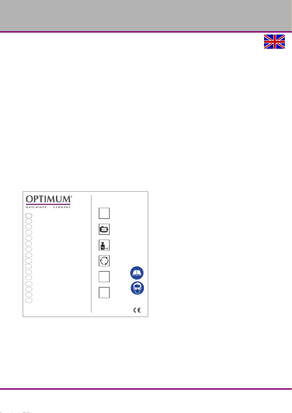
If you would like to order another operating manual for your machine, please indicate the serial
number of your machine. The serial number is located on the type plate.
1.1 Type plate
Always keep this documentation close to the radial drilling machine.
RD5GB
Safety
Version 1.0 2017-03-13Page 6 Original operating instructions
Page 7
OPTIMUM
MASCHINEN - GERMANY
INFORMATION
If you are unable to rectify an issue using these operating instructions, please contact us for
advice:
Optimum Maschinen Germany GmbH
Dr. Robert-Pfleger-Str. 26
D-96103 Hallstadt, Germany
email: [email protected]
1.2 Safety instructions (warning notes)
1.2.1 Classification of hazards
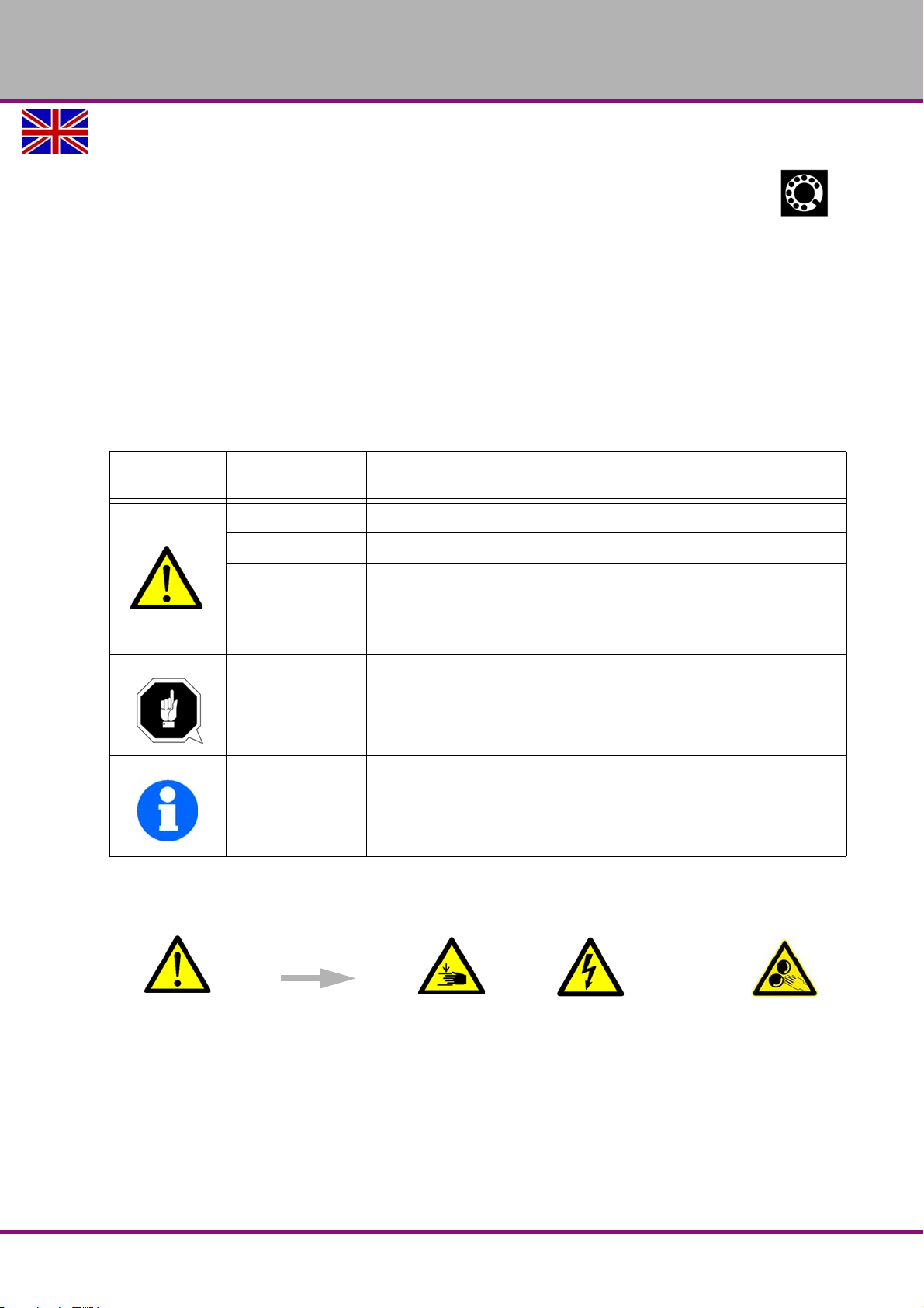
We classify the safety warnings into different categories. The table below gives an overview of
the classification of symbols (ideogram) and the warning signs for each specific danger and its
(possible) consequences.
Symbol
In case of specific dangers, we replace the pictogram with
Alarm expres-
sion
DANGER!
WARNING!
CAUTION!
ATTENTION!
Information
Impending danger that will cause serious injury or death to people.
A danger that can cause serious injury or death.
A danger or unsafe procedure that can cause personal injury or damage to
property.
Situation that could cause damage to the radial drilling machine and products and other types of damage.
No risk of injury to persons.
Practical tips and other important or useful information and notes.
No dangerous or harmful consequences for people or objects.
Definition / consequence
general danger
with a warning of
injury to hands,
hazardous electri-
cal voltage,
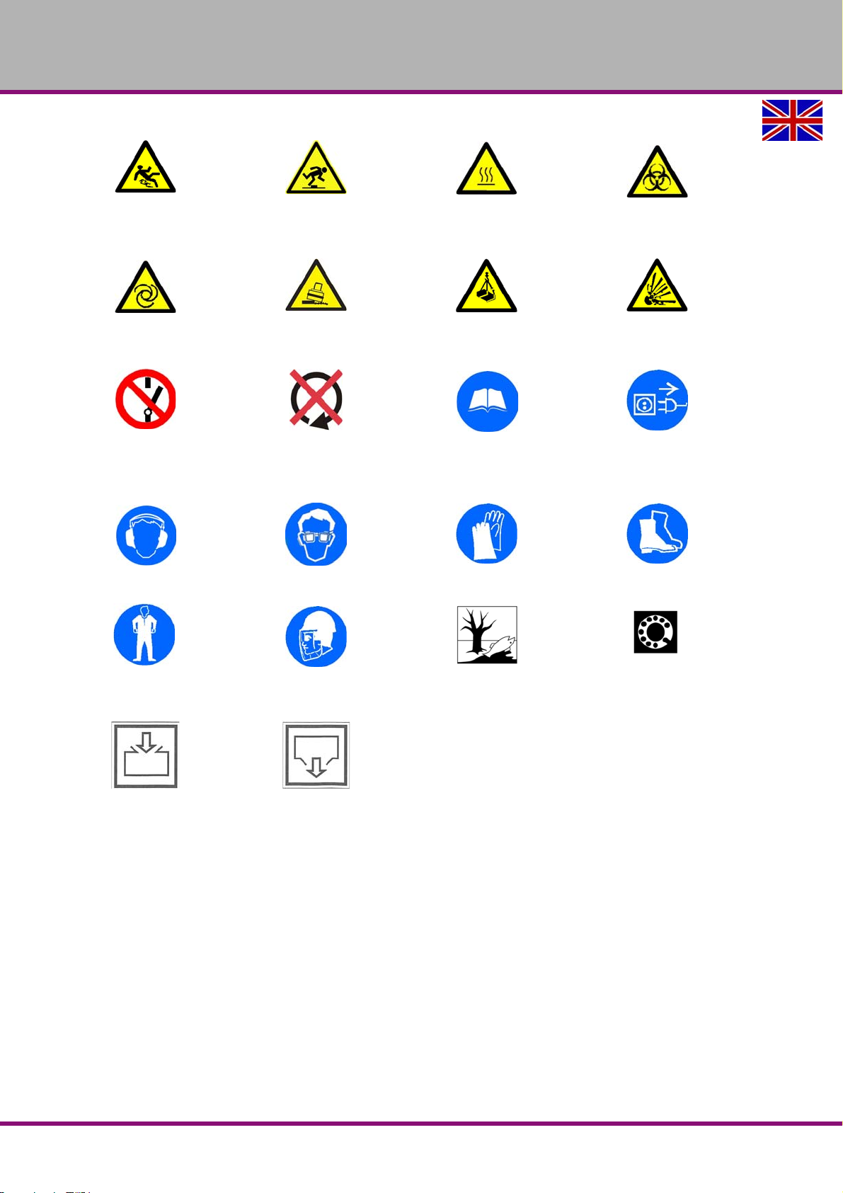
1.2.2 Other pictograms
Safety
Version 1.0 2017-03-13 Page 7Original operating instructions
or
rotating parts.
RD5 GB
Page 8
OPTIMUM
MASCHINEN - GERMANY
Warning: danger of slip-
ping!
Warning: automatic start-
up!
Switching on forbidden! Only switch when stopped!
Use ear protection! Wear protective glasses! Wear protective gloves! Wear safety shoes!
Warning: risk of stumbling!
Warning: tilting danger! Warning: suspended loads! Caution, danger of explo-
Warning: hot surface!
Read the operating instruc-
tions before commission-
ing!
Warning: biological hazard!
sive substances!
Pull out the mains plug!
Wear a protective suit! Wear face protection with
protective helmet!
Oil filler position Oil outlet
Protect the environment!
Contact address
RD5GB
Version 1.0 2017-03-13Page 8 Original operating instructions
Safety
Page 9
OPTIMUM
MASCHINEN - GERMANY
1.3 Intended use
WARNING!
In the event of improper use, the radial drilling machine
will endanger pers onnel,
will endanger the machine and other material property of the operating company,
the correct function of the radial drilling machine may be affected.
The radial drilling machine is designed and manufactured to be used in a non-explosive environment. The radial drilling machine is designed and manufactured for holes in cold metals or
other non flammable materials or that not constitute a health hazard using a rotating filing-stripping tool that has a number of grooves for collecting the filings.
If radial drilling machine is used in any way other than described above, modified without the
approval of the company Optimum Maschinen Germany GmbH then the drilling machine is
being used improperly.
We will not be held liable for any damages resulting from any operation which is not in accordance with the intended use.
We expressly point out that the guarantee or CE conformity will expire due to any constructive
technical or procedural changes which had not been performed by the company Optimum
Maschinen Germany GmbH.
It is also part of intended use that
observe the limits of the radial drilling machine,
the operating manual is observed,
the inspection and maintenance instructions are observed.
"Technical specification“ on page 20
WARNING!
Extremely severe injuries.
It is forbidden to make any modifications or alterations to the operation values of the
radial drilling machine! They could endanger the personnel and cause damage to the
radial drilling machine.
1.4 Reasonably foreseeable misuse
Any other use other than that specified under "Intended use" or any use beyond the described
use shall be deemed as non-intended use and is not permissible.
Any other use has to be discussed with the manufacturer.
It is only allowed to process metal, cold and non-inflammable materials with the radial drilling
machine.
In order to avoid misuse, it is necessary to read and understand the operating instructions
before the first commissioning.
The operators must be qualified.
Safety
Version 1.0 2017-03-13 Page 9Original operating instructions
RD5 GB
Page 10

OPTIMUM
MASCHINEN - GERMANY
1.4.1 Avoiding misuse
Use of suitable cutting tools.
Adapting the speed adjustment and feed to the material and workpiece.
Clamp workpieces firmly and free of vibration.
Always pull out the shift rod on the spindle far enough so that if the workpiece or the clamp
touches the shift rod, the rotation of the spindle are switched off.
WARNING!
Risk of injury caused by flying workpieces.
The workpiece is always to be fixed by a machine vice, jaw chuck or by another
appropriate clamping tool such as for the clamping claws.
Clamp the workpiece in the machine vice. Make sure that the workpiece is firmly clamped in the
machine vice and that the machine vice is firmly clamped onto the machine table.
Use cooling and lubricating agents to increase the durability of the tool and to improve the
surface quality.
Clamp the cutting tools and workpieces on clean clamping surfaces.
Sufficiently lubricate the machine.
Recommendations:
Insert the drill in a way that it is exactly positioned between the three clamping jaws of the
quick action chuck.
When drilling, make sure that
the suitable speed is set depending on the diameter of the drill,
the pressure must only be such that the drill can cut without load,
if there is too much pressure, the drill will wear quickly and may even break or jam in the
borehole. If the drill jams, immediately stop the main motor by pressing the emergency stop
switch,
use commercial cooling/lubricating agents for hard materials, e.g. steel and
generally always back the spindle out of the workpiece while it is still turning.
1.5 Possible dangers caused by the radial drilling machine
The radial drilling machine is state-of-the-art.
Nevertheless, there is a residual risk as radial drilling machine operates with
at high speeds,
with rotating parts,
electrical voltage and currents,
We have used design and safety engineering to minimize the health risk to personnel resulting
from these hazards.
If the radial drilling machine is used and maintained by personnel who are not duly qualified,
there may be a risk resulting from incorrect or unsuitable maintenance of the radial drilling
machine.
INFORMATION
Everyone involved in the assembly, commissioning, operation and maintenance must
be duly qualified,
and strictly follow these operating instructions.
In the event of improper use
there may be a risk to personnel,
there may be a risk to the machine and other material values,
RD5GB
Version 1.0 2017-03-13Page 10 Original operating instructions
Safety
Page 11

OPTIMUM
MASCHINEN - GERMANY
the correct function of the radial radial drilling machine may be affected.
Always disconnect the radial drilling machine, and upright drill if cleaning or maintenance work
is beingcarried out.
WARNING!
The radial drilling machine may only be used with functional safety devices.
Disconnect the radial drilling machine immediately, whenever you detect a failure in the
safety devices or when they are not fitted!
All additional devices installed by the operator have to be equipped with the prescribed
safety devices.
As the operating company, this is your responsibility!
"Safety devices“ on page 13
1.6 Qualification of personnel
1.6.1 Target group
This manual is addressed to
the operating companies,
the operators,
the maintenance personnel.
Therefore, the warning notes refer to both, operation and maintenance personnel of the radial
drilling machine.
Determine clearly and explicitly who will be responsible for the different activities on the
machine (operation, maintenance and repair).
Unclear responsibilities constitute a safety risk!
Always disconnect the main plug of the machine and secure the main switch using a lock. This
will prevent it from being used by unauthorized persons.
The qualifications of the personnel for the different tasks are mentioned below:
Operator
The operator is instructed by the operating company about the assigned tasks and possible
risks in case of improper behaviour. Any tasks performed beyond operation in standard mode
may only be performed by an operator if they are described in these instructions and if the operator has been specifically trained to perform them by the operating company.
Qualified electrician
With professional training, knowledge and experience as well as knowledge of respective
standards and regulations, qualified electricians are able to perform work on the electrical system and recognise and avoid any possible dangers.
Qualified electricians have been specially trained for the working environment, in which they are
working and know the relevant standards and regulations.
Qualified personnel
Due to their professional training, knowledge and experience as well as knowledge of relevant
regulations, qualified personnel are able to perform the assigned tasks and to independently
recognise and avoid any possible dangers.
Instructed person
Instructed persons were instructed by the operating company regarding the assigned tasks and
any possible risks of improper behaviour.
Safety
Version 1.0 2017-03-13 Page 11Original operating instructions
RD5 GB
Page 12

OPTIMUM
MASCHINEN - GERMANY
1.6.2 Authorized persons
WARNING!
Inappropriate operation and maintenance of the radial drilling machine constitutes a
danger for the personnel, objects and the environment.
Only authorized personnel may operate the radial drilling machine !
Persons authorized to operate and maintain should be trained technical personnel and
instructed by the ones who are working for the operating company and for the manufacturer.
The operating company must
train the personnel,
instruct the personnel in regular intervals (at least once a year) on
- all safety regulations relevant to the machine,
- its operation and
- generally accepted engineering standards.
check the personnel‘s knowledge level,
document the training/instruction,
have attendance at the training/instruction confirmed by signature and
check whether the personnel is working in a safety and risk-conscious manner and follow-
ing the operating instructions.
define and document the inspection deadlines for the machine in accordance with § 3 of the
Factory Safety Act and perform an operational risk analysis in accordance with § 6 of the
Work Safety Act.
The operator must
have obtained a training regarding the handling of the radial drilling machine,
know the function and mode of action,
before taking the machine in operation
- have read and understood the operating manual,
- be familiar with all safety devices and instructions.
Additional requirements apply for work on the following machine components:
Electrical parts or operating agents: shall only be performed by an electrician or under the
guidance and supervision of an electrician.
Before starting work on electrical parts or operating agents, following measures are to be
performed in the following order:
disconnect all poles
secure against restarting
check that there is no voltage.
Obligations of
the operating
company
Obligations of
the operator
Additional
requirements
regarding the
qualification
1.7 User positions
The operator’s position is in front of the radial drilling machine.
1.8 Safety measures during operation
CAUTION!
Danger due to inhaling dust and mist that is hazardous to health.
Dependent on the material which need to be processed and the used auxiliaries dusts
and mist may be caused which might impair you health.
Make sure that the generated health hazardous dusts and mist are safely sucked off at
the point of origin and is dissipated or filtered from the working area. To do so, use a
suitable extraction unit.
RD5GB
Version 1.0 2017-03-13Page 12 Original operating instructions
Safety
Page 13
OPTIMUM
MASCHINEN - GERMANY
CAUTION!
Risk of fire and explosion by using flammable materials or cooling lubricants.
Before processing inflammable materials (e.g. aluminium, magnesium) or using
inflammable auxiliary materials (e.g. spirit) it is necessary to take additional preventive
measures in order to safely avoid health risks.
1.9 Safety devices
Use the radial drilling machine only with properly functioning safety devices.
Stop the radial drilling machine immediately if there is a failure on the safety device or if it is not
functioning for any reason.
It is your responsibility!
If a safety device has been activated or has failed, the radial drilling machine must only be used
if you
the cause of the fault has been eliminated,
you have verified that there is no danger to personnel or objects.
WARNING!
If you bypass, remove or deactivate a safety device in any other way, you are
endangering yourself and other personnel working with the radial drilling machine. The
possible consequences are:
injuries may occur due to workpiece or parts of workpieces flying off,
contact with rotating parts,
fatal electrocution,
The radial drilling machine machine includes the following safety devices:
an EMERGENCY STOP push button,
a drilling table with T-slots to fix the workpiece or a vice,
a electromagnetic spindle brake,
an extractable shifting rod with trip device on the spindle,
1.10 Safety check
Check the radial drilling machine before each start-up or at least once per shift. Inform the person responsible immediately of any damage, defects or changes in the operating function.
Check all safety devices
at the beginning of each shift (with the machine stopped),
once a week (with the machine in operation),
after all maintenance and repair work.
Check that prohibition, warning and information signs and the labels on the radial drilling
machine.
are legible (clean them, if necessary)
are complete (replace if necessary).
INFORMATION
Organise the checks according to the following table;
General check
Equipment Check OK
Guards Mounted, firmly bolted and not damaged
Date: checked by (signature):
Safety
Version 1.0 2017-03-13 Page 13Original operating instructions
RD5 GB
Page 14

OPTIMUM
MASCHINEN - GERMANY
General check
Equipment Check OK
Signs,
Markers
Date: checked by (signature):
Functional check
Equipment Check OK
EMERGENCY STOP
push button
Shifting rod with trip
device on the drilling
spindle
Clamping lever
Drilling head - Cantilever
Date: checked by (signature):
Installed and legible
After actuating the EMERGENCY STOP push button the
radial drilling machine must be switched off.
After touching the shift rod, the drilling machine must be
switched off. The drilling machine may not start if the shift rod
is actuated.
The spindle must not start up if the drilling head and cantilever are not clamped.
RD5GB
Version 1.0 2017-03-13Page 14 Original operating instructions
Safety
Page 15
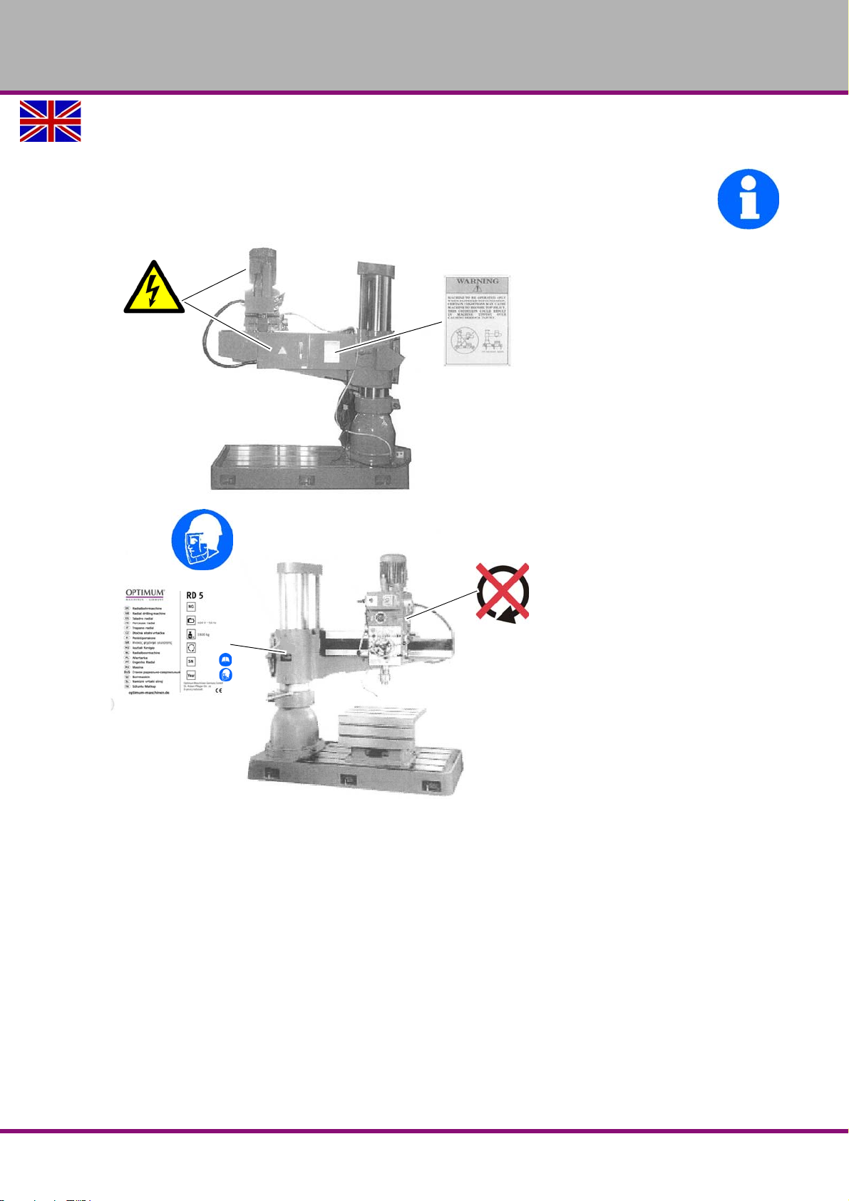
1.10.1 Prohibition, warning and mandatory signs
2.25 KW
37 - 1253
INFORMATION
All warning signs must be legible. They must be checked regularly.
Positioning of the labels
OPTIMUM
MASCHINEN - GERMANY
Safety
Version 1.0 2017-03-13 Page 15Original operating instructions
RD5 GB
Page 16
OPTIMUM
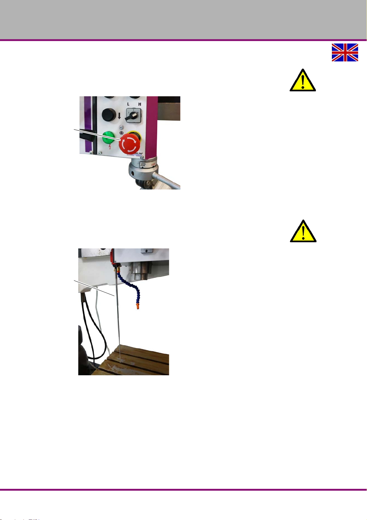
EMERGENCY-Stop
push button
Shift rod
MASCHINEN - GERMANY
1.11 EMERGENCY STOP push button
CAUTION!
The drilling spindle keeps turning for a short time even after actuating the EMERGENCY-
STOP push button depending on the preset speed.
Img.1-1: EMERGENCY-STOP
1.12 Extendable shift rod
CAUTION!
The drilling spindle keeps turning for a short time even after actuating the shift rod
through the workpiece, depending on the preset speed.
Img.1-2: Shift rod
RD5GB
Safety
Version 1.0 2017-03-13Page 16 Original operating instructions
Page 17
OPTIMUM
MASCHINEN - GERMANY
1.12.1 Main switch
WARNING!
Dangerous voltage even if the main switch is switched off.
The areas marked by the pictogram might contain live parts, even if the main switch is switched
off.
In the "0" position, the lockable main switch can be secured against accidental or non-authorised switching on by means of a padlock.
The power supply is interrupted by switching off the main plug.
Except for the areas marked by the pictogram in the margin. In these areas there might be volt-
age, even if the main switch is switched-off.
1.13 Clamping Table
Seats for T-slots are attached to the clamping table.
WARNING!
Risk of injury due to workpieces flying off at high speed. Securely fix the workpiece on
the machine foot or on the drilling table.
1.14 Personal protective equipment
For some works you need personnel protective equipment as protective equipment. These are
safety helmet,
protective glasses or face guard,
protective gloves,
safety shoes with steel toe caps,
ear protection.
Before starting work make sure that the required personnel protective equipment is available at
the work place.
CAUTION!
Dirty or contaminated personnel protective equipment can cause illness.
Clean your personal protective equipment
after each use,
regularly once a week.
Personal protective equipment for special works
Protect your face and your eyes: Wear a safety helmet with facial protection when performing
work where your face and eyes are exposed to hazards.
Wear protective gloves when handling pieces with sharp edges.
Wear safety shoes when you assemble, disassemble or transport heavy components.
Safety
Version 1.0 2017-03-13 Page 17Original operating instructions
RD5 GB
Page 18
OPTIMUM
MASCHINEN - GERMANY
1.15 Safety during operation
We specifically point out the dangers when describing the work with and on the radial drilling
machine.
WARNING!
Before switching on the radial drilling machine make sure that there are
no dangers generated for persons,
no objects are damaged.
Avoid any unsafe work methods:
Make sure that your operation does not create a safety hazard.
The rules specified in these operating instructions must be observed during assembly,
operation, maintenance and repair.
Do not work on the radial drilling machine, if your concentration is reduced, for example,
because you are taking medication.
Observe the accident prevention regulations issued by your Employers Liability Insurance
Association or other supervisory authorities applicable to your company.
Inform the supervisor about all hazards or faults.
Stay on the radial drilling machine until the machine completely stopped moving.
Use the prescribed personnel protective equipment. Make sure to wear a well-fitting work
suit and, if necessary, a hairnet.
Do not use protective gloves when drilling.
1.16 Safety during maintenance
Inform the operators in good time of any maintenance and repair works.
Report all safety relevant changes and performance details of the radial drilling machine or their
operational behavior. Any changes must be documented, the operating instructions updated
and machine operators instructed accordingly.
1.16.1 Disconnecting and securing the radial drilling machine
Switch off the radial drilling machine with the main switch and secure the main switch with a
padlockagainst unauthorised switching-on or switching-on by accident.
All machine parts as well as any dangerous voltages are switched off. Excepted are only the
positions which are marked with the adjoining pictogram.
1.17 Using lifting equipment
WARNING!
The use of unstable lifting and load suspension equipment that might break under load
can cause severe injuries or even death.
Check that the lifting and load suspension gear
they have sufficient load carrying,
and that it is in perfect condition.
Observe the accident prevention regulations issued by your Employers Liability
Insurance Association or other supervisory authorities applicable to your company.
Fasten the loads properly. Never walk under suspended loads!
RD5GB
Version 1.0 2017-03-13Page 18 Original operating instructions
Safety
Page 19

OPTIMUM
MASCHINEN - GERMANY
1.17.1 Mechanical maintenance
Reinstall all protection and safety devices after any maintenance work once the work has been
completed.This includes:
covers,
safety instructions and warning signs,
grounding cables.
Check if they are working properly!
1.18 Accident report
Inform your supervisors and Optimum Maschinen Germany GmbH immediately in the event of
accidents, possible sources of danger and any actions which almost led to an accident (near
misses).
There are many possible causes for "near misses".
The sooner they are notified, the quicker the causes can be eliminated.
1.19 Electronics
Have the machine and/or the electric equipment checked regularly. Immediately eliminate all
defects such as loose connections, defective wires, etc.
A second person must be present during work on live components to disconnect the power in
the event of an emergency. Disconnect the machine immediately if there is a malfunction in the
power supply!
Comply with the required inspection intervals in accordance with the factory safety directive,
operating equipment inspection.
The operator of the machine must ensure that the electrical systems and operating equipment
are inspected with regards to their proper condition, namely,
by a qualified electrician or under the supervision and direction of a qualified electrician,
prior to initial commissioning and after modifications or repairs, prior to recommissioning
and at certain intervals.
The deadlines must be set so that arising, foreseeable defects can be detected in a timely manner.
The relevant electro-technical rules must be followed during the inspection.
The inspection prior to initial commissioning is not required if the operator receives confirma-
tion from the manufacturer or installer that the electrical systems and operating equipment comply with the accident prevention regulations, see conformity declaration.
Permanently installed electrical systems and operating equipment are considered constantly
monitored if they are continually serviced by qualified electricians and inspected by means of
measurements in the scope of operation (e.g. monitoring the insulation resistance).
1.20 Inspection deadlines
Define and document the inspection deadlines for the machine in accordance with § 3 of the
Factory Safety Act and perform an operational risk analysis in accordance with § 6 of the Work
Safety Act. Also use the inspection intervals in the maintenance section as reference values.
Safety
Version 1.0 2017-03-13 Page 19Original operating instructions
RD5 GB
Page 20
OPTIMUM
MASCHINEN - GERMANY
2 Technical specification
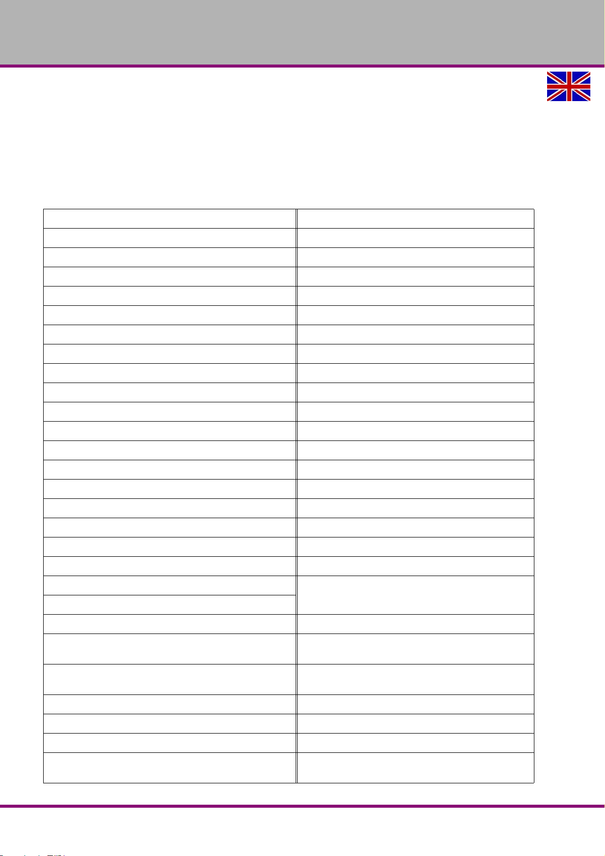
The following information represents the dimensions and indications of weight and the manufacturer‘s approved machine data. The calculated envisaged life of the machine to EN ISO
13849 and EN ISO 12100 is at least 10 years with a daily operation of 8h at 220 working days
per year when keeping to the ambient conditions, proper use and keeping to the required maintenance intervals. Safety-related replacement parts are included in this calculation. Normal
replacement parts such as, for example, bearings, are not part of this calculation.
Electrical connection 3x400V ~50 Hz / 60Hz 7.853 KVA
Driving power spindle motor 2.25 KW
Driving power hoist motor cantilever arm 0.75 KW
Driving power cooling lubricant pump 0.1 KW
Drilling capacity in steel (S235JR) [mm] 42
Drilling capacity in cast steel [mm] 55
Tapping in steel (S235JR) M24
Tapping in cast steel M38
Feed speed spindle sleeve [mm/rotation] 3 stages │ 0.05 │ 0.09 │ 0.153
Automatic drilling depth shut-off [mm] 10 until 110
Spindle speed when connecting [ 50 Hz ] 37 - 1253 rpm
Spindle speed when connecting [ 60 Hz ] 44 - 1500 rpm
Speed steps motor + gear drive 12
Spindle seat MT4
Spindle sleeve travel [mm] 230
Angle of rotation of cantilever + - 180°
Machine weight 1800 kg
Weight including packaging 1950 kg
Floor loading 16 KN / m
Machine height [mm]
Dimensions of machine base
Groove distance, groove size for clamping table
Unloading, maximum distance from the column surface to
the centre of the spindle [mm]
2
"Space required for the machine“ on page 23
"Work area“ on page 23
"T-slots, seats for clamping table“ on page 22
1100
Unloading, minimum distance from the column surface to
the centre of the spindle [mm]
Column diameter [mm] 260
Drilling head travel horizontal [mm] 820
Drilling head travel vertical [mm] 570
Maximum distance from the spindle nose to the surface of
the machine base [mm]
RD5GB
280
1270
Technical specification
Version 1.0 2017-03-13Page 20 Original operating instructions
Page 21

OPTIMUM
MASCHINEN - GERMANY
Minimum distance from the spindle nose to the surface of
the machine base [mm]
Environmental conditions temperature +5 to +40 °C
Environmental conditions of rel. humidity 30% to 95% at 40°C ; 90 % at 20°C
Environmental conditions storage and transport -25°C to +55 °C
Spindle gear
Gear for lifting device of
cantilever
Lubricator Mobilgear 626
Operating material
Spindle grease nipple Water repellent grease,
"Lubricant“ on page 73
Cantilever screw spindle
Cooling lubricant
Water mixable, nebular
arm, high flash point,
nitrite content of the emul-
sion is less than 20 mg/l
470
Mobilgear 626
4.5 litres
Mobilgear 626
Mobilux EP 0
or
Mobil Greaserex 47
About 20 liters
2.1 Emissions
Measurement according to operating conditions
The noise development (emission) of the radial drilling machine is 73 dB(A) at a rotary speed of
1252 rpm, measured at a metre's distance from the gearbox at a height of 1.6m when the
machine is idling.
The noise development (emission) of the radial drilling machine is 70 dB(A) at a rotary speed of
74 rpm, measured at a metre's distance from the gearbox at a height of 1.6m when the
machine is idling.
If the radial drilling machine is installed in an area where various machines are in operation, the
noise exposure (immission) on the operator of the radial drilling machine at the working place
may exceed 80 dB(A).
INFORMATION
This numerical value was measured on a new machine under the operating conditions specified
by the manufacturer. The noise behaviour of the machine might change depending on the age
and wear of the machine.
Furthermore, the noise emission also depends on production engineering factors, e.g. speed,
material and clamping conditions.
INFORMATION
The specified numerical value represents the emission level and does not necessarily a safe
working level.
Though there is a dependency between the degree of the noise emission and the degree of the
noise disturbance it is not possible to use it reliably to determine if further precaution measures
are required or not.
The following factors influence the actual degree of the noise exposure of the operator:
Characteristics of the working area, e.g. size of damping behaviour,
Technical specification
Version 1.0 2017-03-13 Page 21Original operating instructions
RD5 GB
Page 22
OPTIMUM
420
640
520
121 121
19
31,50
100
245
20
MASCHINEN - GERMANY
other noise sources, e.g. the number of machines,
other processes taking place in proximity and the period of time, during which the operator
is exposed to the noise.
Furthermore, it is possible that the admissible exposure level might be different from country to
country due to national regulations.
This information about the noise emission should, however, allow the operator of the machine
to more easily evaluate the hazards and risks.
CAUTION!
Depending on the overall noise exposure and the basic threshold values, machine
operators must wear appropriate hearing protection.
We generally recommend the use of noise and ear protection.
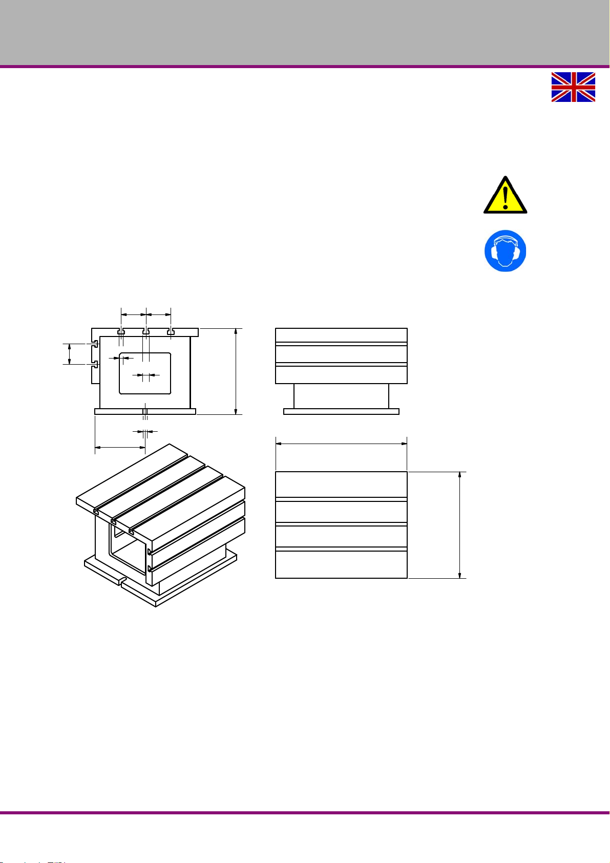
2.2 T-slots, seats for clamping table
Img.2-1: Clamping table, dimension in [mm]
RD5GB
Technical specification
Version 1.0 2017-03-13Page 22 Original operating instructions
Page 23
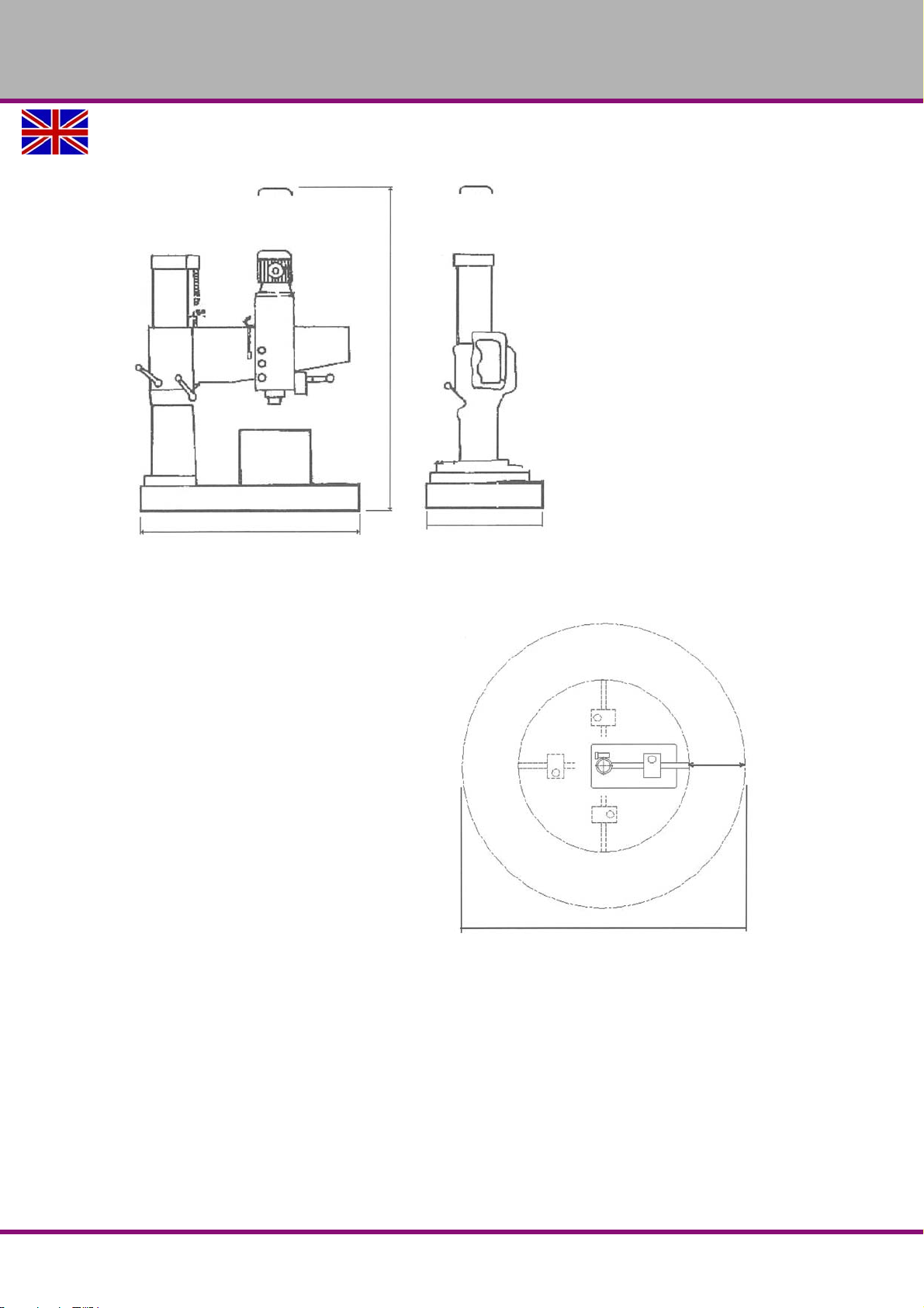
2.3 Space required for the machine
1750mm
745mm
max. 2550mm
1000mm
4856mm
OPTIMUM
MASCHINEN - GERMANY
2.3.1 Work area
Keep a work area of at least one metre around
the machine free for operation and maintenance.
Distance from the centre of the column to the
end of the cantilever is 1428mm.
Technical specification
Version 1.0 2017-03-13 Page 23Original operating instructions
RD5 GB
Page 24
OPTIMUM
MASCHINEN - GERMANY
3 Assembly
3.1 Unpacking the machine
Leave the machine nearby its definite position before unpacking. If the packaging shows signs
of possible transport damage, take the necessary precautions not to damage the machine
when unpacking. If any damage is discovered, the carrier and/or shipper must immediately be
notified of this fact to establish any claim which might arise.
Inspect the machine completely and carefully, making sure that all materials, such as shipping
documents, manuals and accessories supplied with the machine have been received.
3.1.1 StandardAccessories
Toolbox contains:
- 1 x oil bottle for oiler
- 1 x grease press for grease nipple
- 1 set of Allen keys
- 2 x drill drift wedge
- 1 x cross-head and slotted screwdriver
Including:
- 1 x clamping table
- 6 x adjusting shims for levelling the machine.
- 6 x threaded rod M16 x 240 with nuts and washers for anchoring to the floor.
- 6 x adjusting screws 5/8" UNC, already screwed into the substructure
- 1 x printed operating manual.
Optional anchor bolts DIN 529 M16 x 320 are not supplied.
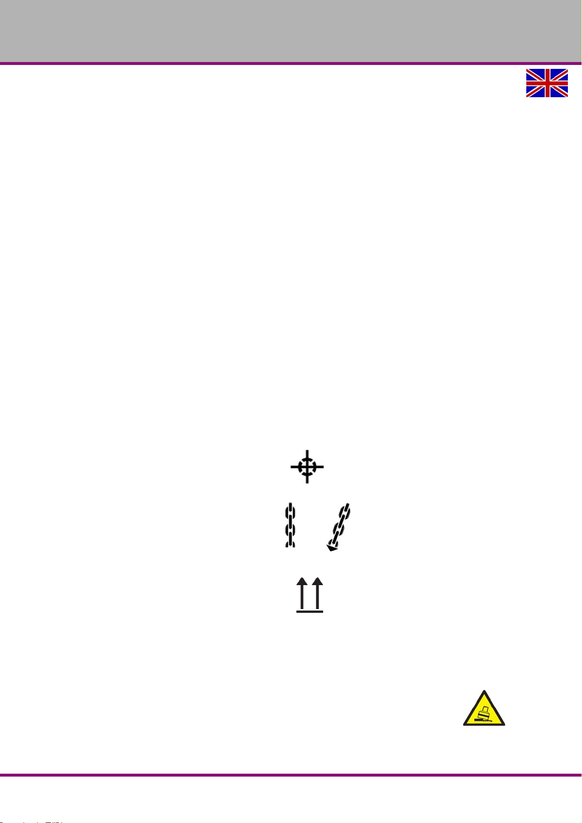
3.2 Transport
Centres of gravity
Load suspension points
(Marking of the positions for the
load suspension gear)
Prescribed transport position
(Marking of the top surface)
Means of transport to be used
Weights
WARNING!
Severe or fatal injuries may occur if parts of the machine tumble or fall down from the
forklift truck or from the transport vehicle. Follow the instructions and information on
the transport box.
RD5GB
Version 1.0 2017-03-13Page 24 Original operating instructions
Assembly
Page 25
OPTIMUM
2.5 t
MASCHINEN - GERMANY
WARNING!
The use of unstable lifting and load suspension equipment that might break under load
can cause severe injuries or even death. Check that the lifting and load suspension gear
has sufficient load capacity and that it is in perfect condition.
Observe the accident prevention regulations issued by your Employers Liability
Insurance Association or other supervisory authorities applicable to your company.
Fasten the loads properly. Never walk under suspended loads!
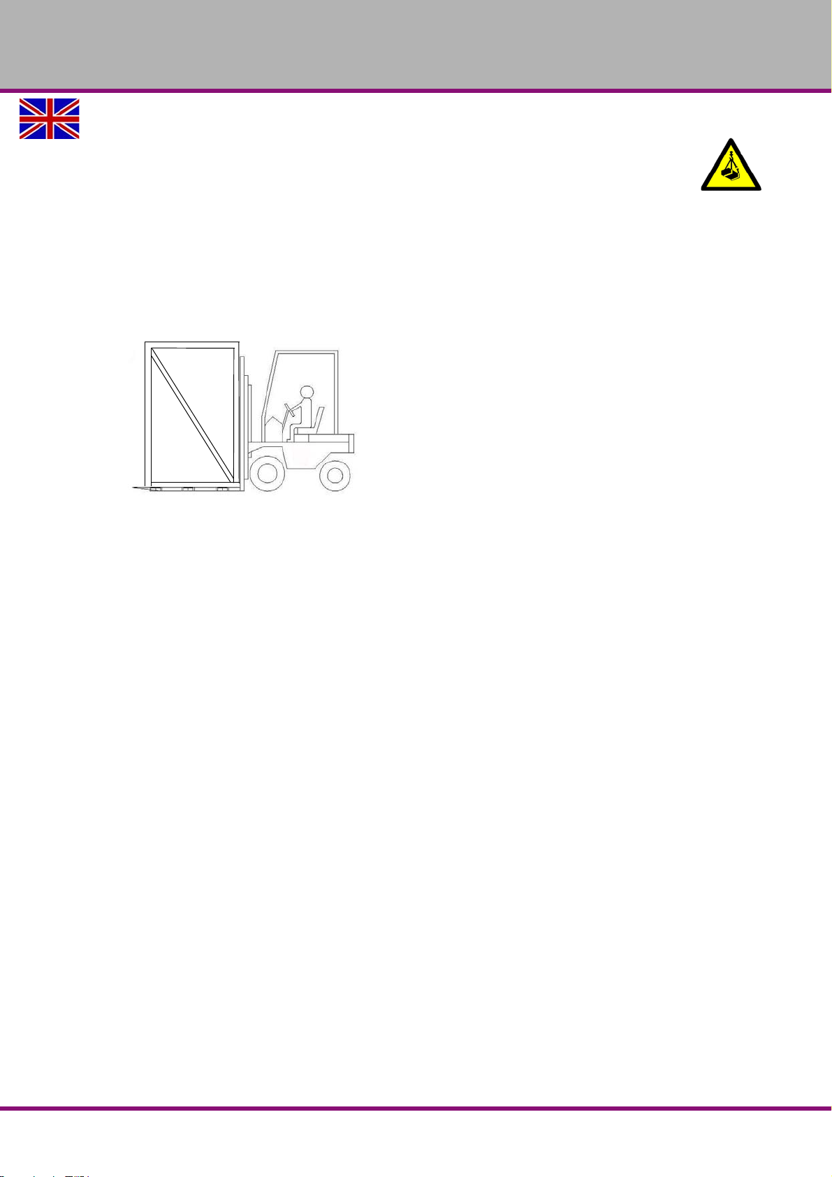
3.3 Load suspension point
The machine can be raised with a forklift truck underneath the packing case.
“Weight including packaging“ on page 20
Assembly
Version 1.0 2017-03-13 Page 25Original operating instructions
RD5 GB
Page 26
OPTIMUM
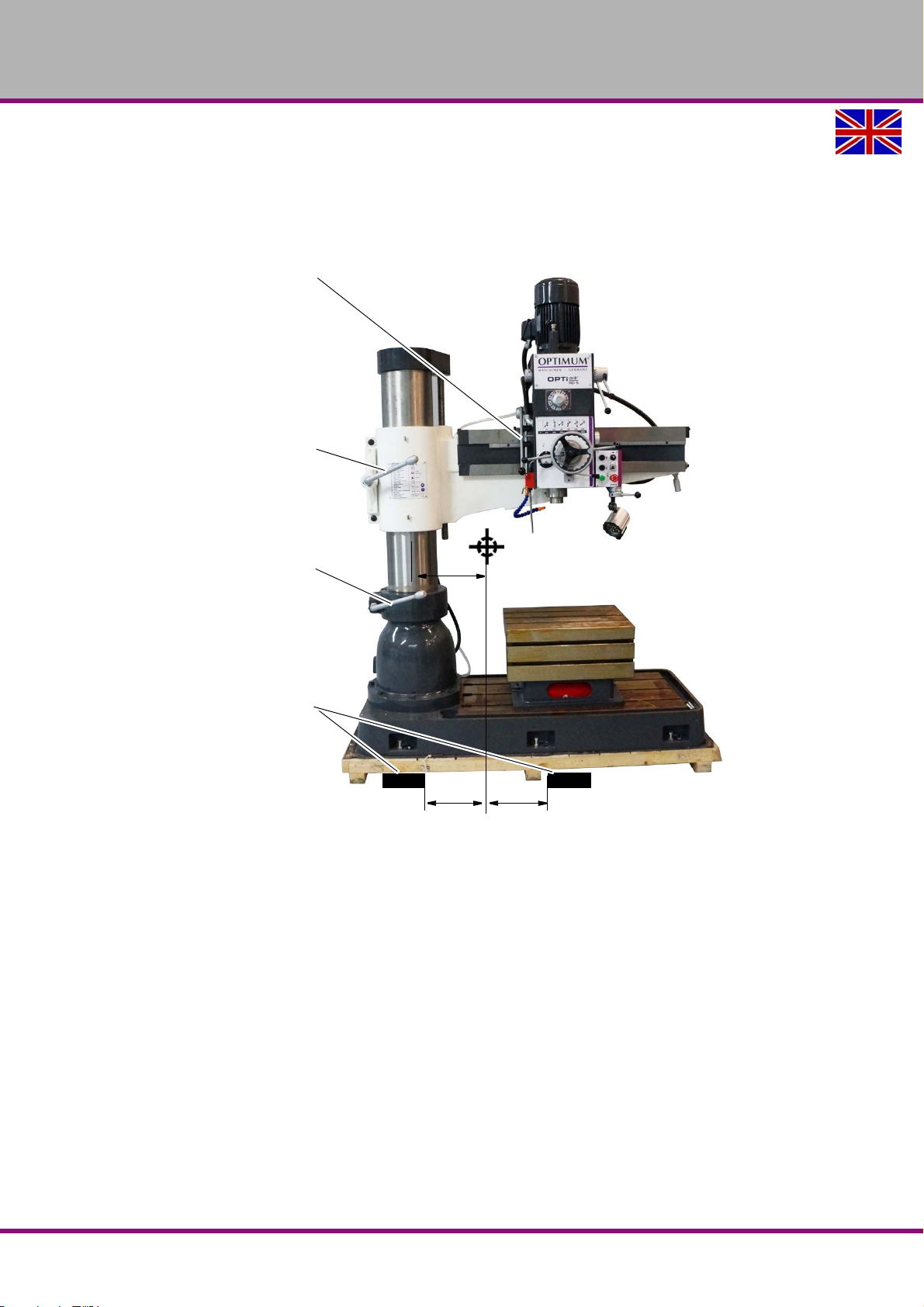
200
Clamping lever drill head
Clamping lever of cantilever
Clamping lever of the column
Forks of the forklift
175
175
MASCHINEN - GERMANY
Distance from the Centre of Gravity when Transporting Packing Case
Transport the closed packing case and lift the packing case as shown in the illustration with
a forklift truck.
Check the substructure. The substructure must bear the load.
Transport the radial drilling machine to the installation site using a forklift truck.
Img.3-1: Distance from centre of gravity
Disassemble the lateral parts of the wooden box.
Check the safe fixture of the cantilever arm and the drilling head. The cantilever is sup-
ported with a beam.
Check whether all the clamping levers are firmly pulled.
RD5GB
Version 1.0 2017-03-13Page 26 Original operating instructions
Assembly
Page 27
OPTIMUM
All clamping levers
are to be tightened
Protective mat
MASCHINEN - GERMANY
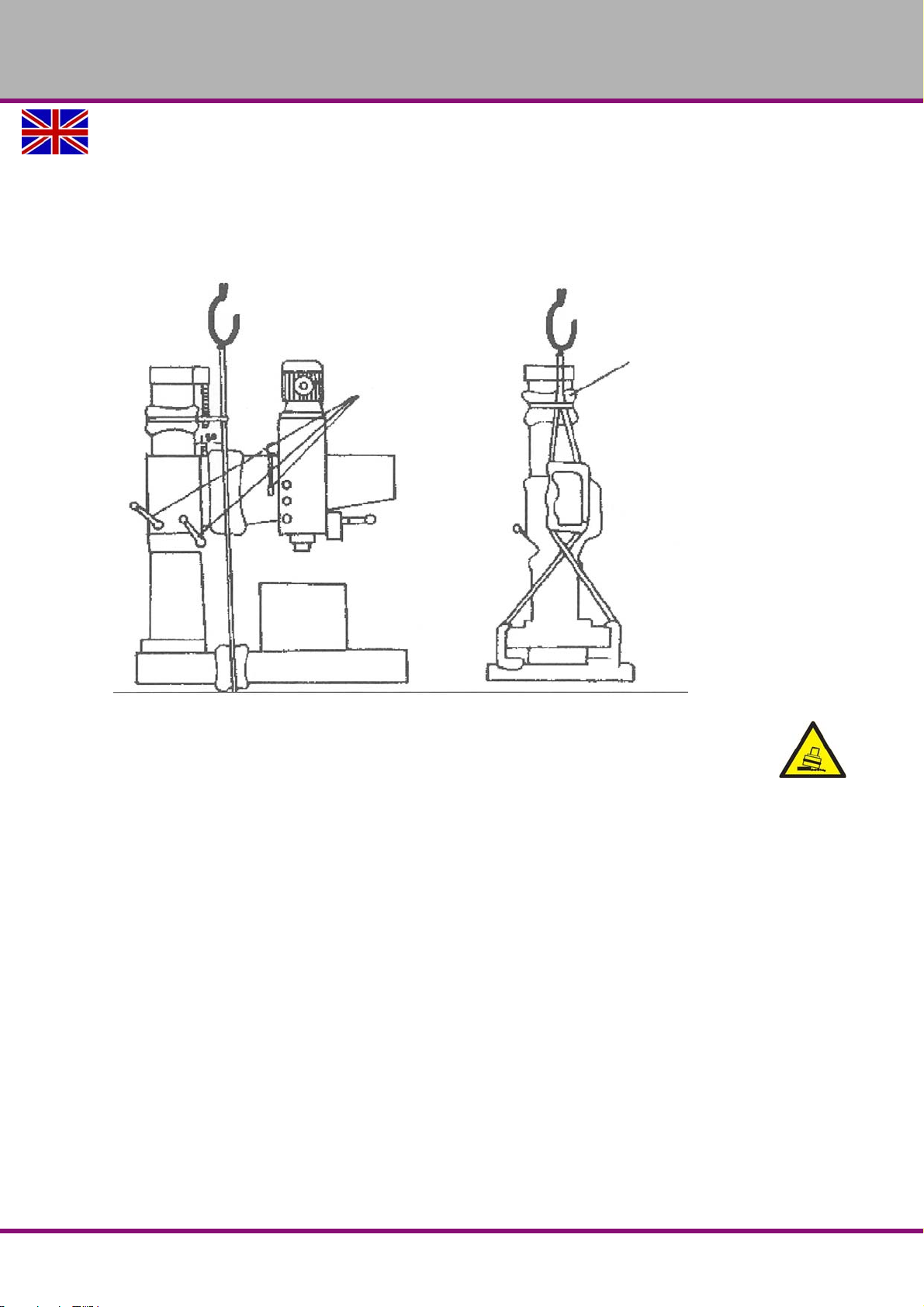
Lift the Machine from the Pallet
The machine load impact is illustrated as follows.
Remove the fastening bolts that are used to fasten the machine on the pallet.
Take care with the centre of gravity of the radial drilling machine.
Lift the radial drilling machine with a crane carefully from the pallet.
Img.3-2: Load suspension for lifting
WARNING!
Risk of toppling the radial drilling machine.
Only undo the clamping lever if the machine is anchored firmly to the base. Only remove
the support for the cantilever if the machine is anchored firmly to the base.
Assembly
Version 1.0 2017-03-13 Page 27Original operating instructions
RD5 GB
Page 28
OPTIMUM
MASCHINEN - GERMANY
3.4 Set-up and assembly
3.4.1 Requirements regarding the installation site
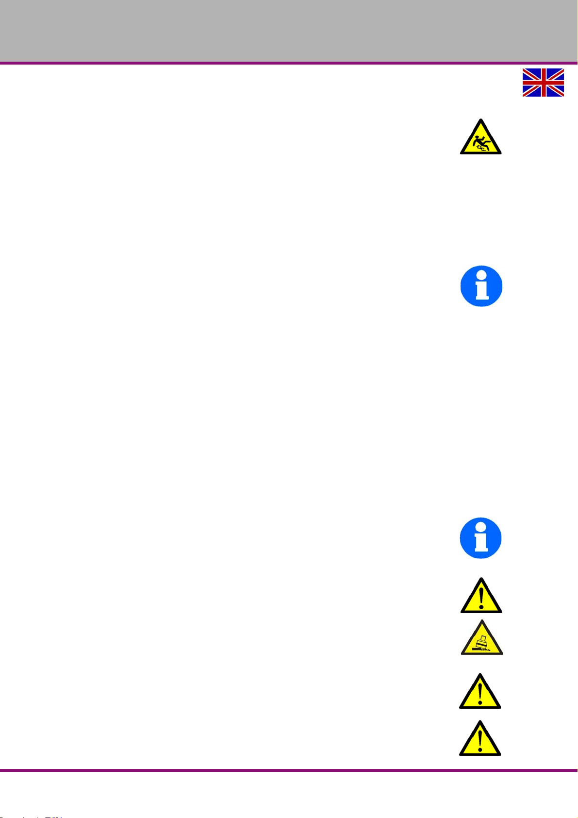
In order to achieve sufficient safety against falls by slipping, the accessible area in the mechanical machining zone of the machine must be equipped with a slip resistant mat and/or floor. The
slip resistant mat and/or the slip resistant floor must be at least R11 according to BGR 181. The
risk assessment of the machine determines whether or not this is needed.
The shoes used must be suitable for being used in those machining areas. The accessible
areas must be cleaned.
Organise the working area around the machine according to the local safety regulations.
"Work area“ on page 23
The work area for operation, maintenance and repair must not be restricted.
INFORMATION
In order to attain good functionality and a high processing accuracy as well as a long service life
of the machine, the place of installation should fulfil certain criteria.
Please observe the following points:
The device must only be installed and operated in a dry and well-ventilated place.
Avoid places near machines generating chips or dust.
The installation site must be free from vibrations also at a distance of presses, planing
machines, etc.
The substructure must be suitable for the radial drilling machine. Also make sure that the
floor has sufficient load bearing capacity and is level.
The ground must be prepared in a way that potential coolants cannot penetrate the floor.
Any parts sticking out such as stops, handles, etc. have to be secured by measures taken
by the customer if necessary in order to avoid endangering persons.
Provide sufficient space for the personnel preparing and operating the machine and trans-
porting the material.
Also make sure the machine is accessible for setting and maintenance works.
Provide for sufficient backlight (Minimum value: 500 lux, measured at the tool tip). At lower
illumination intensities, additional illumination has to be ensured e.g. by means of a separate workplace lamp.
INFORMATION
The mains plug of the radial drilling machine must be freely accessible.
3.4.2 Assembly
WARNING!
Danger of crushing and overturning.
The installation of the radial drilling machine must be performed by at least 2 persons.
3.5 Setting up RD5
WARNING!
The condition of the underground and the fixing type of the machine foot to the
underground must be in a way that it can bear the loads of the radial drilling machine.
WARNING!
First fix the machine so that it stands stable on the substructure before performing any
further installation works or disassembling the transportation locks. The foundation on
RD5GB
Version 1.0 2017-03-13Page 28 Original operating instructions
Assembly
Page 29
OPTIMUM
MASCHINEN - GERMANY
which the machine is anchored must have sufficient load bearing capacity. In any case
commission a structural engineer who can check if the place of installation has
sufficient load bearing capacity. Please observe that there is tensile loading and
additional punctual load on the foundation while turning the cantilever against the
direction of the machine foot.
Check the horizontal orientation of the base of the drilling machine with a spirit level.
Check that the foundation has sufficient load-bearing capacity and rigidity.
Place the radial drilling machine on the provided underground.
Align the machine.
Fix the radial drilling machine in the provided through-holes on the machine foot.
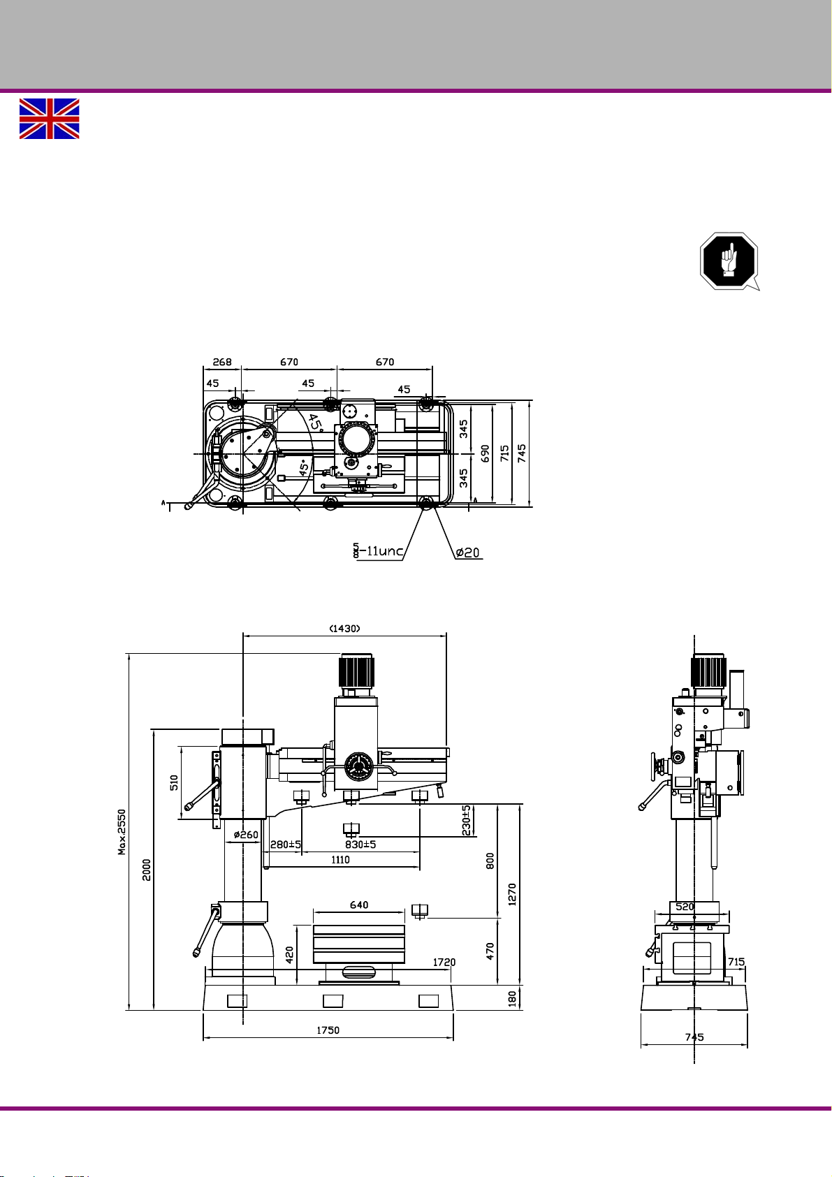
3.6 Installation plan
Assembly
Version 1.0 2017-03-13 Page 29Original operating instructions
RD5 GB
Page 30
OPTIMUM
1
6
1725
670 670 160
690
715
5/8 - UNC
Ø20
40
300 180
300
1 3
6
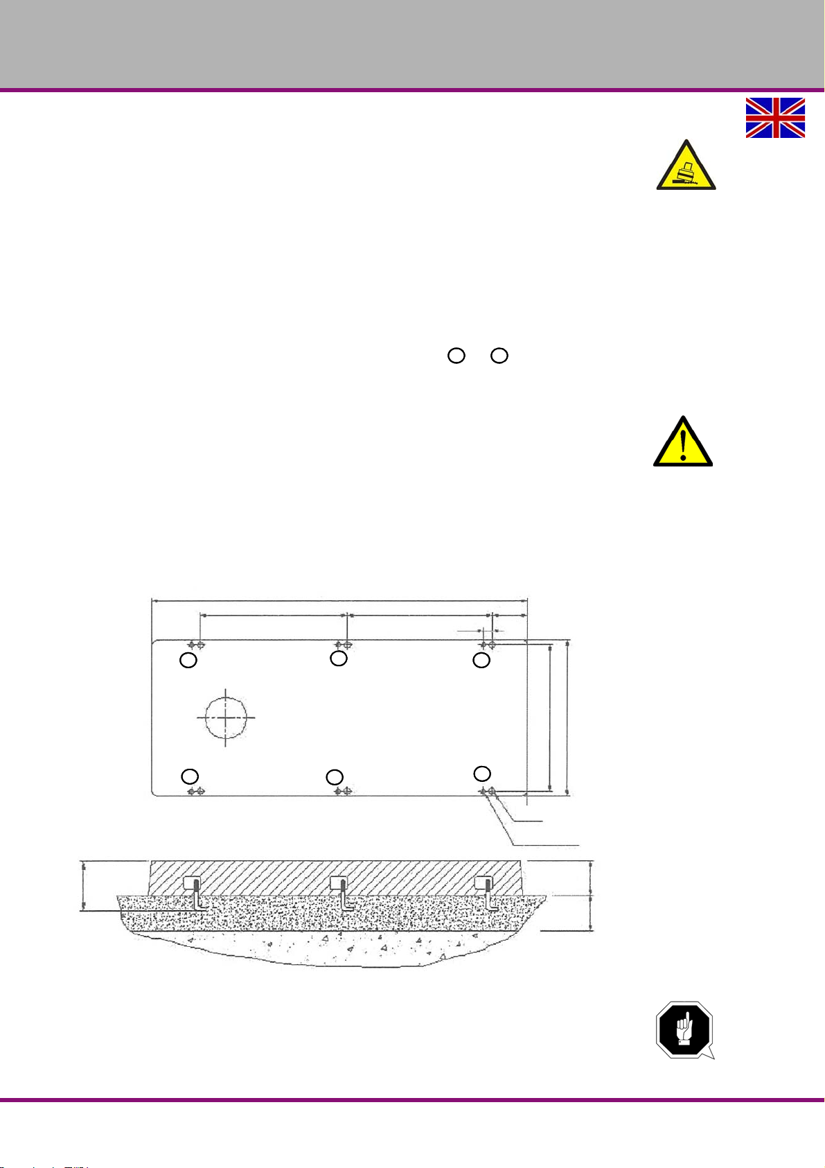
1-6 adjusting screws 5/8 UNC with lock washers
2
4
5
MASCHINEN - GERMANY
3.6.1 Aligning the machine
WARNING!
Risk of toppling the radial drilling machine.
Only undo the clamping lever if the machine is anchored firmly to the base.
Only remove the transport locks when the machine is anchored firmly to the base.
"Transport locking devices“ on page 33
Align the radial drilling machine on the cantilever or on the machine base by means of a
machine spirit level. The slope deviation of all levels must not exceed 1/1000mm. The more
precisely the cantilever has been aligned with a possible inclination with the adjusting
screws to the machine base, the smaller the cantilever can turn by itself around the column, when the clamping lever is released.
Use the adjusting shims in the scope of supply at positions to .
Align the machine with the adjusting screws.
3.6.2 Fixing
WARNING!
In order to provide for the necessary stability of the radial drilling machine connect the
machine with its foot to the substructure.
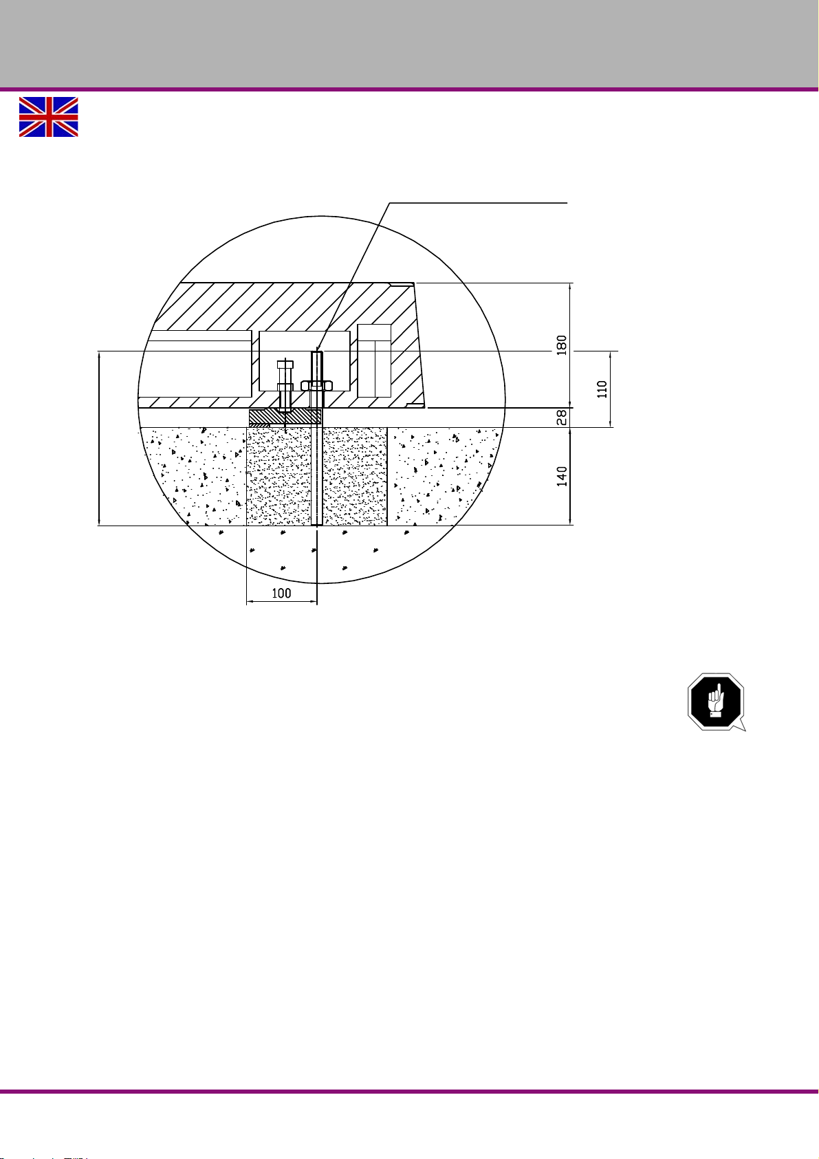
Use the threaded rods supplied 5/8" x 250. We recommend you use anchor bolts DIN 529 M16
x 250 .
Fix the foot of the radial drilling machine to the substructure with the provided through-
holes.
Img.3-3: Attachment points on machine foot
ATTENTION!
Tighten the nuts of the anchor bolts or threaded rods only so far that they are safely
fixed and the machine foot cannot break away or the machine can tilt over.
RD5GB
Version 1.0 2017-03-13Page 30 Original operating instructions
Assembly
Page 31
OPTIMUM
5/8" x 250
MASCHINEN - GERMANY
If the fixing screws are too tight in particular in connection with an uneven substructure it may
result in a broken stand of the machine bed.
3.7 Top up oil, check oil level
ATTENTION!
The radial drilling machine is delivered without oil filling. First fill in oil before starting
the radial drilling machine.
"Oil sight glass spindle gear“ on page 47
"Oil sight glass gear Lifting device Cantilever“ on page 47
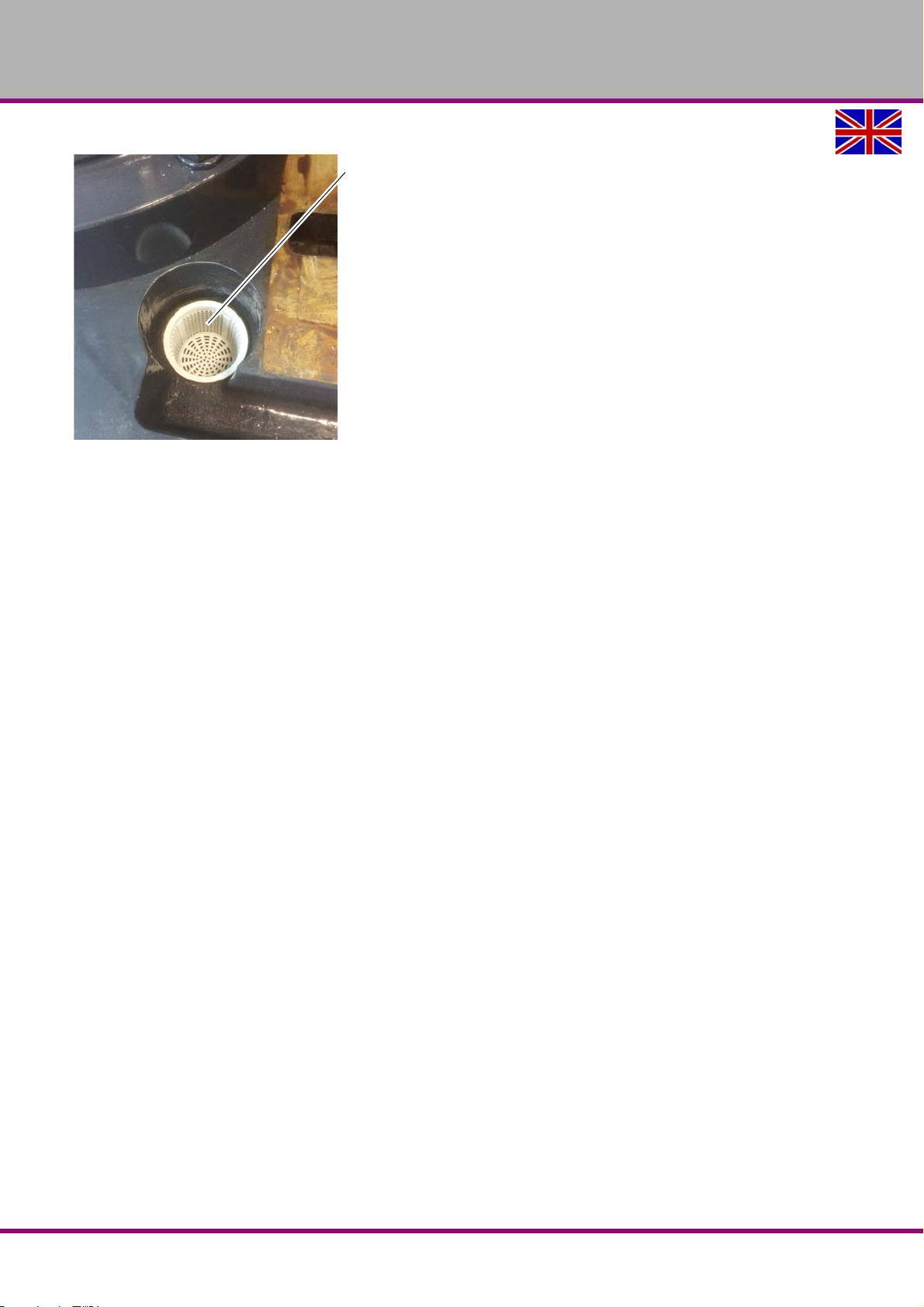
3.8 Coolant tank
Fill in the tank with a suitable coolant. Fill it up to a maximum of the centre of the wedge wire filter.
"Lubricant“ on page 73
"Operating material“ on page 21
Assembly
Version 1.0 2017-03-13 Page 31Original operating instructions
RD5 GB
Page 32
OPTIMUM
Filler hole
Slotted screen
MASCHINEN - GERMANY
Img.3-4: Coolant tank in the machine foot
3.8.1 One-component paint
The radial drilling machine is lacquered with a one-component paint. Observe this fact when
selecting your cooling lubricant and cleaning of the radial drilling machine.
A one-component lacquer with solvent part hardens when the solvent evaporates.
As soon as the lacquer is applied the solvent evaporates into the air. The binder becomes
felted and a dry film is formed. This process is reversible, i.e. the binder can be etched again
and again.
Two-component lacquer also consists of binder and solvent. However, the lacquer dries only in
connection with an added hardener. This process is not reversible, i.e. the binder cannot be
etched again and again.
The company Optimum Maschinen Germany GmbH does not assume any guarantee for subsequent damages due to unsuitable cooling lubricants.
RD5GB
Version 1.0 2017-03-13Page 32 Original operating instructions
Assembly
Page 33
OPTIMUM
Clamping lever
Lock screw
MASCHINEN - GERMANY
3.9 Transport locking devices
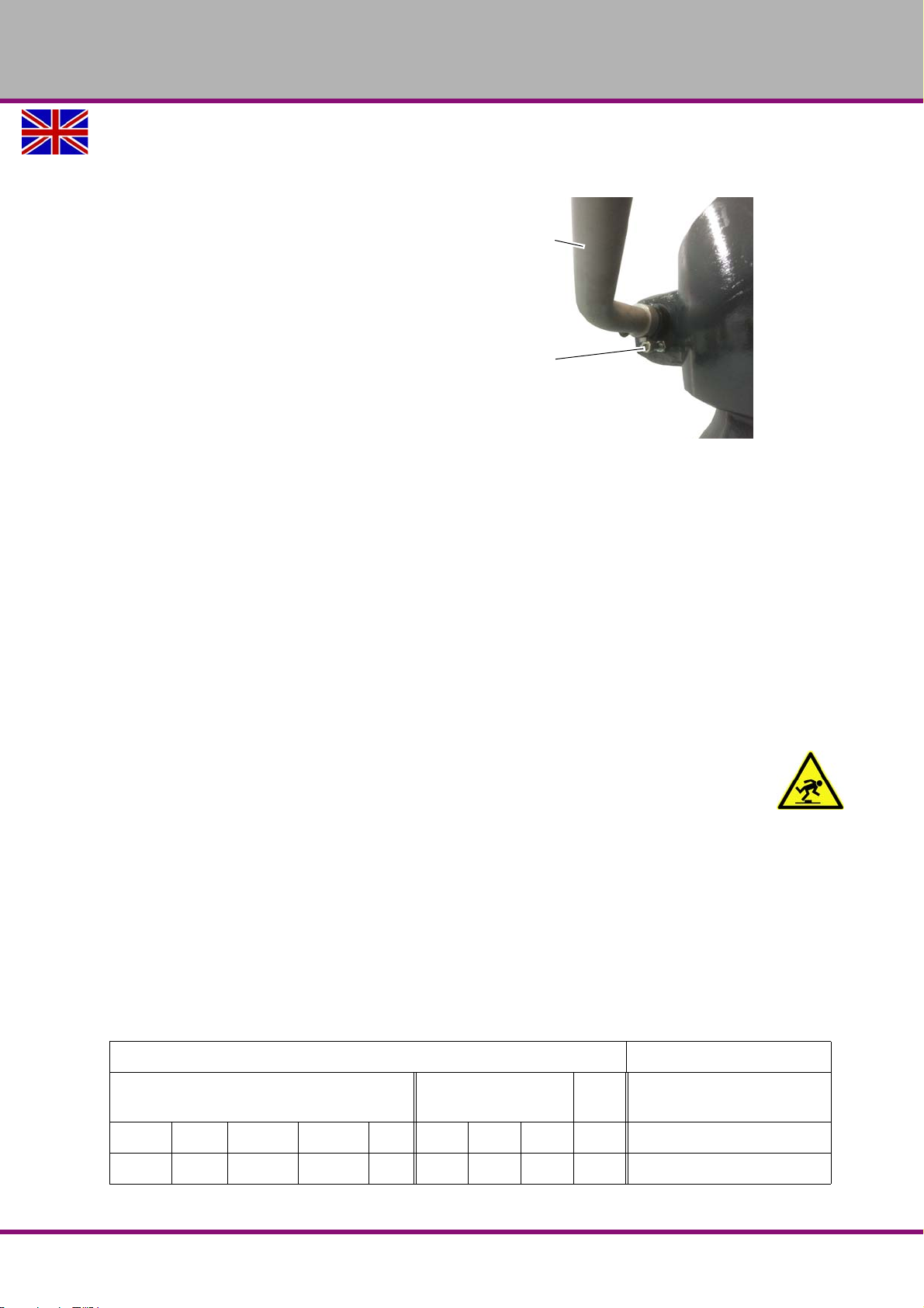
Remove transport locks.
Remove beam to support the cantilever.
Remove lock screw on the clamping lever
of the column.
Img.3-5: Lock screw
3.10 Cleaning and lubrication
Remove the anti-corrosive agents on the radial drilling machine which had been applied for
transportation and storage. We recommend you use paraffin for this purpose.
Do not use any solvents, thinner or other cleaning agents which could corrode the varnish
on the radial drilling machine. Observe the cleaning agent manufacturer's information and
notes.
Grease all exposed machine parts using an acid-free lubricating oil.
Lubricate the radial drilling machine according to the lubricating plan.
"Maintenance“ on page 43
Check if all spindles are running smoothly.
3.10.1 Electrical connection
CAUTION!
Install the connection cable of the machine in such a way that people will not stumble
over it.
Please verify if the type of current, voltage and protection fuse correspond to the values specified. A protective earth ground wire connection must be available.
min. connection cross section per phase and earthing: 3.5mm
Electrical connection power: 7.853 KVA
Permitted voltage fluctuations under normal operation: ± 10% Volt
Permitted frequency fluctuations: ± 1Hz (50/60 Hz)
Permitted instantaneous shutdown period: 10 ms
Permitted voltage pulse: 200% or less than the actual value of the mains voltage (effective
Permitted unevenness of a phase: 5% or less
2
value): 1.5 ms
Electrical connection AC ± 10%; 1 Ø; 50/60Hz ±1Hz
Connection cross-section of phase conductor [ mm
220V 380V 415V 440V PE 220V 380V 415V 440V
3.5 3.5 3.5 3.5 3.5 16.2 9.87 9.14 8.53 7.853
2
]
Rated current [ A ] Connection power [ KVA ]
Assembly
Version 1.0 2017-03-13 Page 33Original operating instructions
RD5 GB
Page 34
OPTIMUM
MASCHINEN - GERMANY
ATTENTION!
Ensure that all 3 phases (L1, L2, L3) and the ground wire are connected correctly.
The neutral conductor (N) of its power supply is not connected.
ATTENTION!
Make sure that the direction of rotation of the drive motor is correct. The switch position
of the rotation selector switch for right-handed rotation (R) has to turn the drill spindle
clockwise. If necessary, exchange two phase connections.
The automatic spindle sleeve feed moves in the wrong direction and components may
be damaged when it reaches the end stop.
The guarantee will become null and void if the machine is connected incorrectly.
3.11 First commissioning
The machine may only be commissioned after proper installation.
ATTENTION!
Before initially operating the machine, check all screws, fixtures and/or safety devices,
and tighten up the screws if necessary!
WARNING!
The use of improper tool holders or their operation at inadmissible speeds constitutes a
hazard.
Only use the tool holders (e.g. drill chuck) which were delivered with the machine or
which are offered as optional equipment by OPTIMUM.
Only use tool holders in the intended admissible speed range.
Tool holders may only be modified in compliance with the recommendation of OPTI-
MUM or of the manufacturer of the clamping devices.
WARNING!
When first commissioning the radial drilling machine by inexperienced personnel you
endanger people, the machine and the equipment.
We do not assume any liability for damages caused by incorrectly performed
commissioning.
„Qualification of personnel“ auf Seite 11
3.11.1 Warming up the machine
ATTENTION!
If the radial drilling machine and in particular the drilling spindle is immediately operated
at maximum load when it is cold, it may result in damages.
If the machine is cold, e.g. directly after having transported the machine, it should be warmed
up at a spindle speed of only 500 rpm for the first 30 minutes.
RD5GB
Version 1.0 2017-03-13Page 34 Original operating instructions
Assembly
Page 35
4 Operation
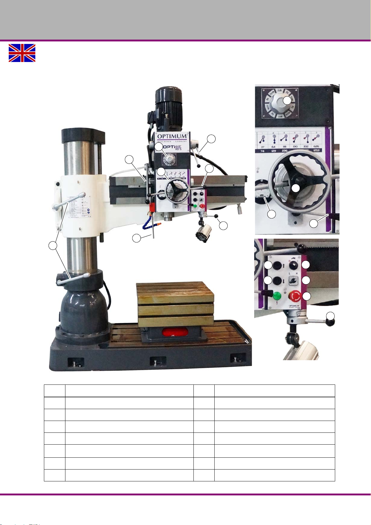
1
1
2
3
4
6
7
5
2
3
11
12
6
14
13
8
9
10
4.1 Control and indicating elements
OPTIMUM
MASCHINEN - GERMANY
H
10 Emergency-Stop button
Item Designation Item Designation
1 Clamping lever 2 Selection of spindle sleeve feed
3 Move hand wheel on drilling head 4 Quill lever
6 Direction of rotation lever 5 Gear lever
7 Extendable shift rod 8 Coolant pump ON / OFF
9
11 Current consumption of spindle drive [ A ] 12 Clamping lever for drilling depth stop
Stepper switch for drive motor L │
13 Lift cantilever 14 Lower cantilever
Operation
Version 1.0 2017-03-13 Page 35Original operating instructions
RD5 GB
Page 36
OPTIMUM
MASCHINEN - GERMANY
4.2 Safety
Commission the machine only under the following conditions:
The machine is in proper working order.
The machine is used as prescribed.
Follow the operating instructions.
All safety devices are installed and activated.
All failures should be eliminated immediately. Stop the machine immediately in the event of any
anomaly in operation and make sure it cannot be started up accidentally or without authorisation
Notify the person responsible immediately of any modification.
"Safety during operation“ on page 18
4.3 Before starting work
Before starting work, select the desired speed. This will depend on the diameter of the bit being
used and the material. Use the tables on the machine.
INFORMATION
The data of the speed tables are guide values. In some cases it may be advantageous to
increase or decrease these values.
A cooling or lubricating agent should be used when drilling.
The workpieces must always be clamped firmly and stably.
If required, adjust the desired drilling depth by means of the drilling depth stop in order to obtain
a uniform drilling depth.
Please make sure to use a suitable dust suction when treating wood since wood dust may be
health hazardous. Wear a suitable dust mask when performing works at which dust is generated.
WARNING!
Feed in of clothes and / or hair.
Make sure to wear well-fitting work during drilling work.
Do not use gloves.
If necessary, use a hairnet.
WARNING!
For drilling jobs, it is necessary to clamp the workpiece firmly to prevent the bit catching
on the pieces. A suitable clamping tool is a machine vice, clamping jaws, or a device for
clamping production parts.
RD5GB
Version 1.0 2017-03-13Page 36 Original operating instructions
Operation
Page 37
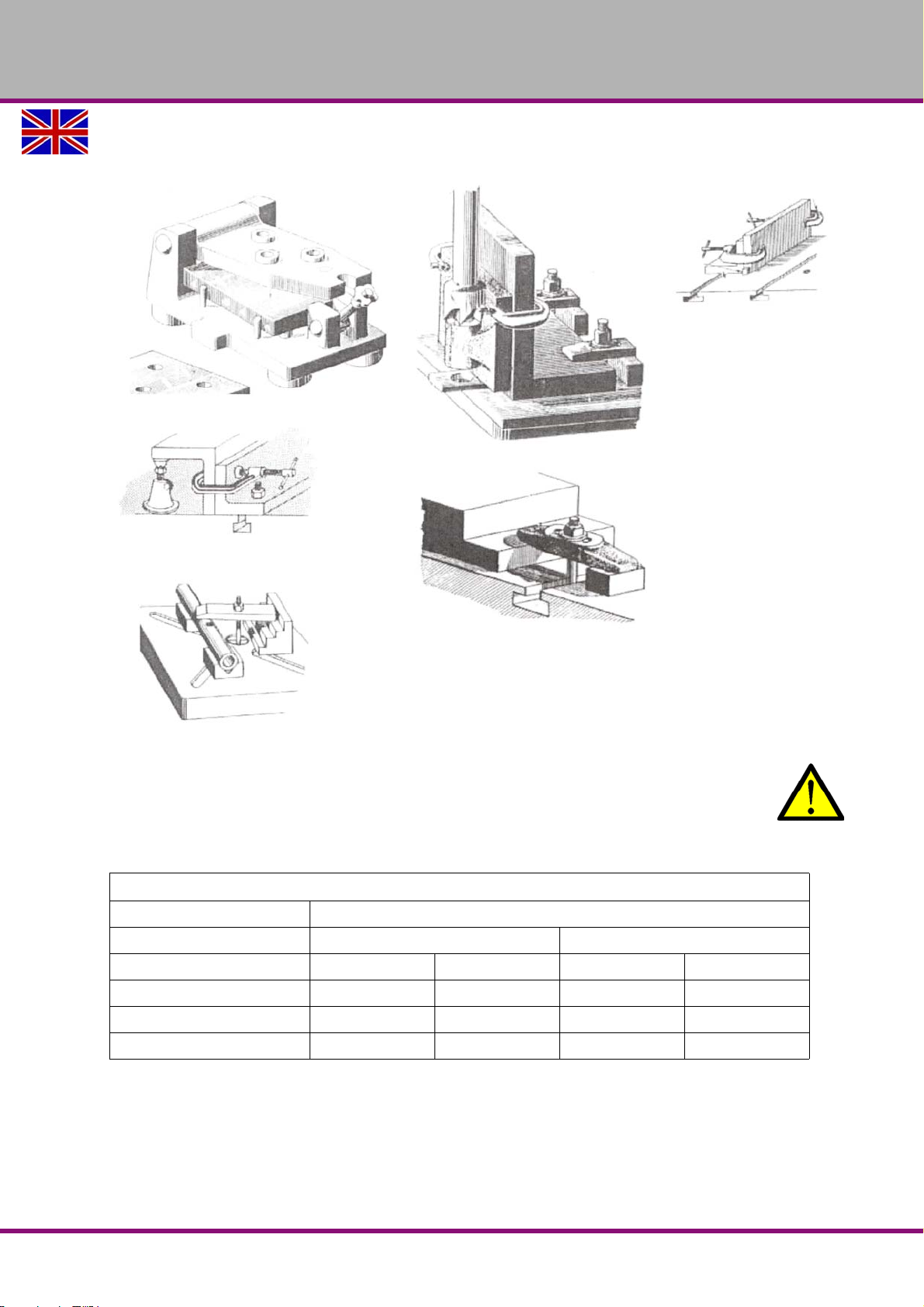
Examples:
OPTIMUM
MASCHINEN - GERMANY
CAUTION!
When tightening very heavy workpieces, reasonable stress loads on the operator or
assembler may be exceeded.
Turn the cantilever towards the rear and load the table with a crane or another suitable
loading device.
Recommended threshold values when lifting and carrying loads
Reasonable load in kg and frequency of lifting and carrying
Occasionally More frequently
Age in years Women Men Women Men
15 - 18 15 35 10 20
19 - 45 15 55 10 30
above 45 15 45 10 25
Operation
Version 1.0 2017-03-13 Page 37Original operating instructions
RD5 GB
Page 38
OPTIMUM
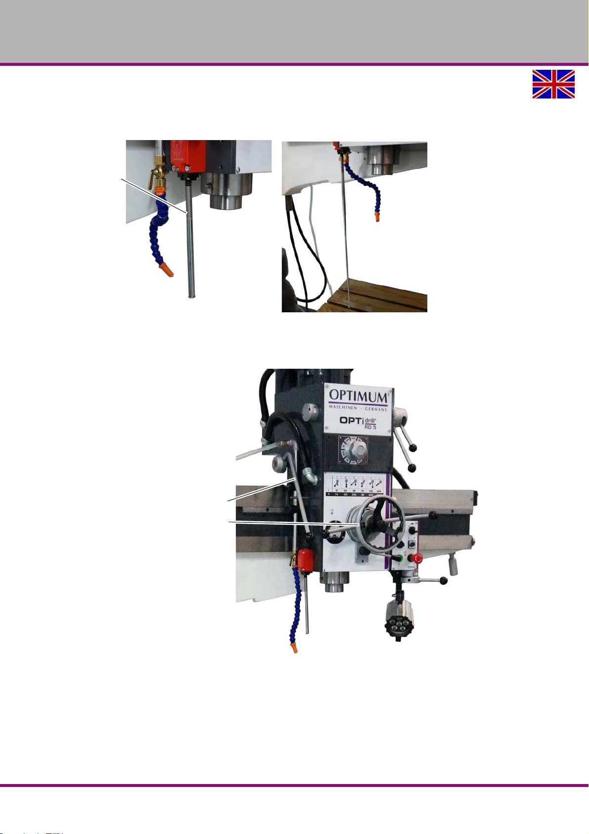
Shift rod
Release the clamping lever.
Move the drilling head with the hand
wheel.
Retighten the clamping lever
Clamping lever
Hand wheel
MASCHINEN - GERMANY
4.4 Adjusting shift rod
Pull out the suitable length of shift rod. When shift rod comes into contact with something or
when the workpiece or the clamp breaks loose, the machine must shut down.
Img.4-1: Shift rod extended
4.5 Moving drilling head
RD5GB
Img.4-2: Drilling head with cantilever
Operation
Version 1.0 2017-03-13Page 38 Original operating instructions
Page 39
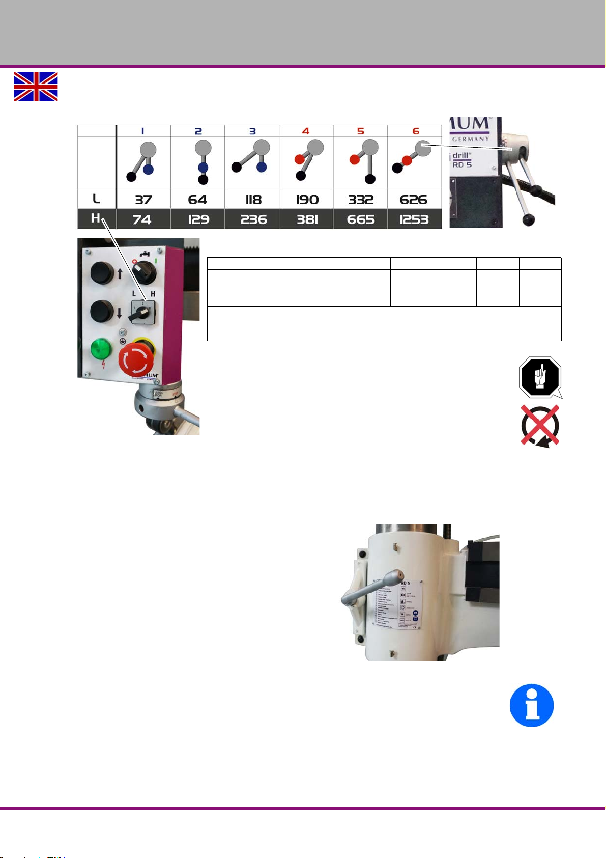
4.6 Speed adjustment
Guide values for speeds:
ATTENTION!
Only change the speed when stationary. If needed, start the
spindle rotation and stop again to make throwing the gear
lever easier.
Speed min
-1
74 129 236 381 665 1253
Steel (S235JR) Ø25 - 40 Ø19 - 25 Ø12 - 19 Ø10 - 12 Ø6 - 10 Ø3 - 6
Steel casting Ø38 - 55 Ø28 - 38 Ø22 - 28 Ø19 - 22 Ø10 - 19 Ø3 - 10
Tapping M16-20 M6-16 M3-6 - - useable
automatic
drill feed
3 stages │ 0.05 │ 0.09 │ 0.153
OPTIMUM
MASCHINEN - GERMANY
4.7 Switching on the machine
Switch on the main switch and the operating indicator comes on.
Unlock the EMERGENCY STOP switch.
Firmly clamp the cantilever and drilling head.
Set the stepper switch of the drive motor to L or H.
L - Low speed range.
H - High speed range.
Set the speed on the selector lever
Turn the rotation direction lever to the desired posi-
tion.
Move the spindle sleeve down with the feed lever.
INFORMATION
Move the spindle sleeve down with the feed lever. The spindle starts to turn as soon as it
leaves the upper end position.
The spindle shuts down as soon as it reaches the lower end posit ion.
The spindle only turns if the cantilever has been firmly clamped.
Img.4-3: Clamping lever of cantilever
Operation
Version 1.0 2017-03-13 Page 39Original operating instructions
RD5 GB
Page 40
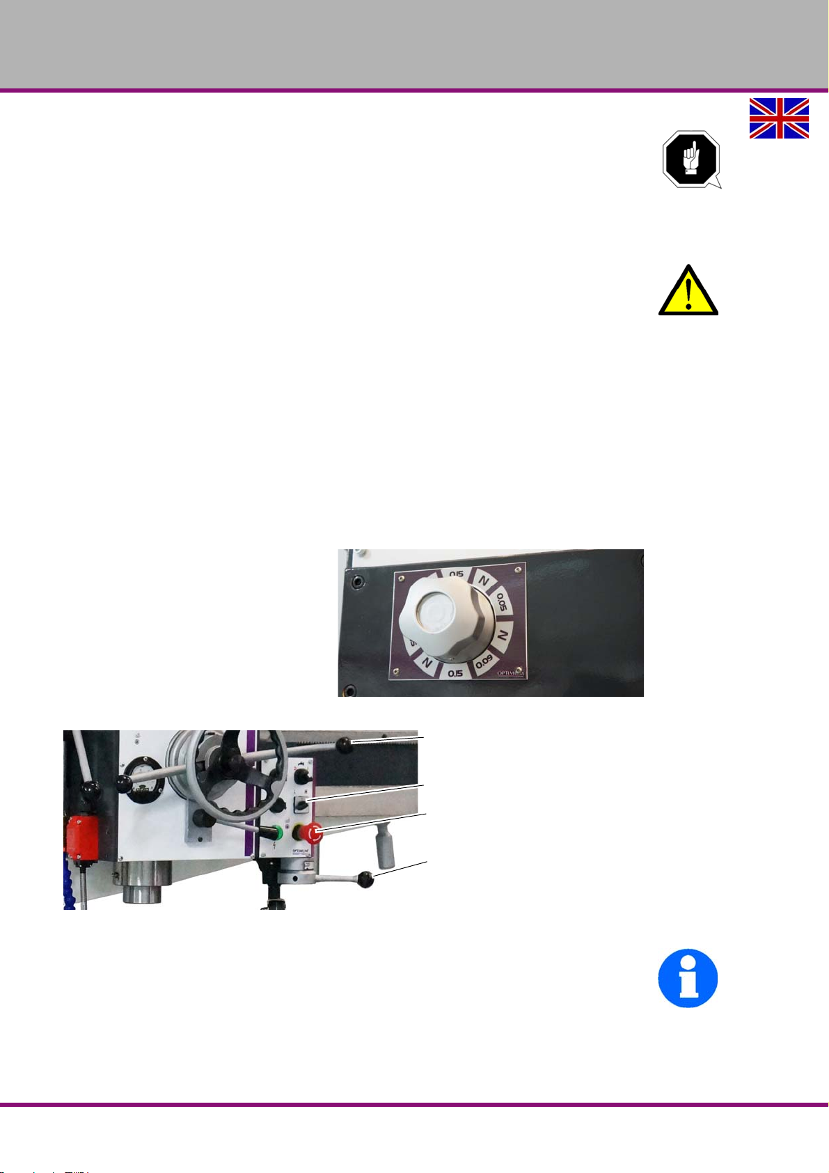
OPTIMUM
Quill lever
Drive step switch
Emergency stop mushroom button
Rotation direction shift lever
MASCHINEN - GERMANY
ATTENTION!
To protect the mechanical end stop of the drilling sleeve, the spindle is switched off on
reaching the lowest position. Please make sure that the end stop is not reached.
Through halt of the the drill spindle, the workpiece can be torn loose.
4.8 Switching off the machine
CAUTION!
Always turn the rotation direction lever and stepper switch of the drive motor to the neu-
tral middle position as soon as the machine is left unattended.
Always turn the stepper switch of the drive motor to the neutral central position.
If the machine is lying idle for a long time, switch it off at the main switch.
4.9 Resetting an emergency stop condition
Set the rotational direction control lever to the neutral position.
Unlock the emergency stop switch again.
4.10 Power failure: Restoring readiness for operation
Put the rotation direction shift lever into the neutral position, and the operating indicator
comes on again.
4.11 Automatic drilling feed
Select spindle sleeve feed. If needed,
briefly start the spindle and stop again,
so that the gear position can be engaged
better.
Move the drilling spindle sleeve down so
that the spindle starts to turn.
Pull out the quill lever and the automatic
spindle sleeve feed is started.
Img.4-5: Drill head
Img.4-4: Select feed
INFORMATION
The ammeter shows you the current consumption of the drive motor.
Make sure that the current consumption is not too high. The current consumption
increases considerably if the rotation speed is too low and the feed is too high.
RD5GB
Version 1.0 2017-03-13Page 40 Original operating instructions
Operation
Page 41
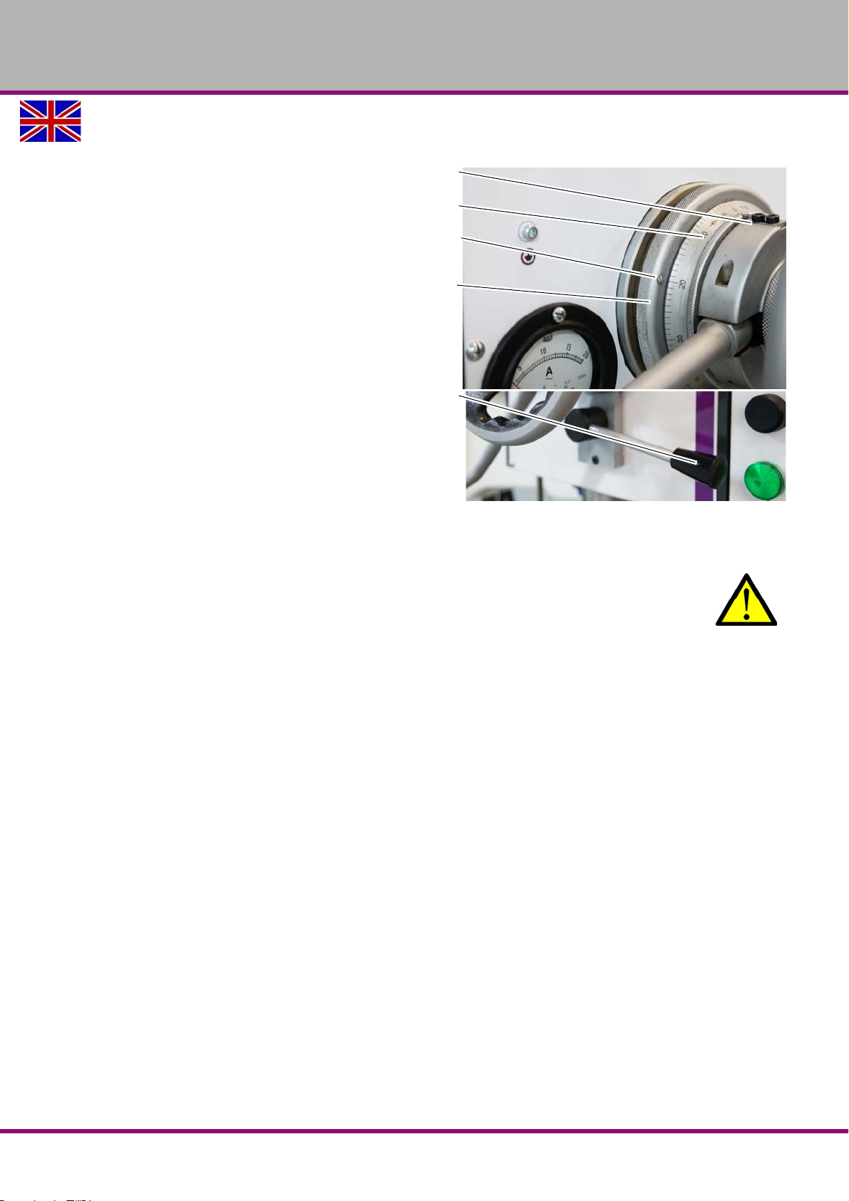
4.11.1 Adjusting the drill depth shutdown
Zero marker
Scale
Marking boring depth
Dial disc
Clamping lever
Turn the dial until the desired
drilling depth corresponds to
the marking on the scale.
Fasten the dial with the lever.
When reaching the set drill-
ing depth, the quill lever
jumps mechanically to the
"drilling depth marking", the
feed stops and the spindle
continues to turn.
The maximum drilling shutdown
is one rotation of the dial.
OPTIMUM
MASCHINEN - GERMANY
4.12 Disassembly, assembly of drill chucks and drill bits
CAUTION!
Make sure that the clamped tool is firmly and correctly fitted.
4.12.1 Fitting the drill chuck
The drill chuck or the tool is secured in the drill spindle against turning over by means of a formlocking connection.
A frictionally engaged connection keeps and centres the drill chuck or the drill in the drill spindle.
Check and, if necessary, clean the conical seat in the drilling spindle and at the taper man-
drel of the tool or the drill chuck.
Press the taper mandrel into the drilling spindle.
4.12.2 Unfitting the drill chuck
Set the step switch to the neutral central position.
Switch off the master switch.
Turn the spindle by hand until the ejection openings are over each other.
Img.4-6: Example drilling depth 20mm
Operation
Version 1.0 2017-03-13 Page 41Original operating instructions
RD5 GB
Page 42
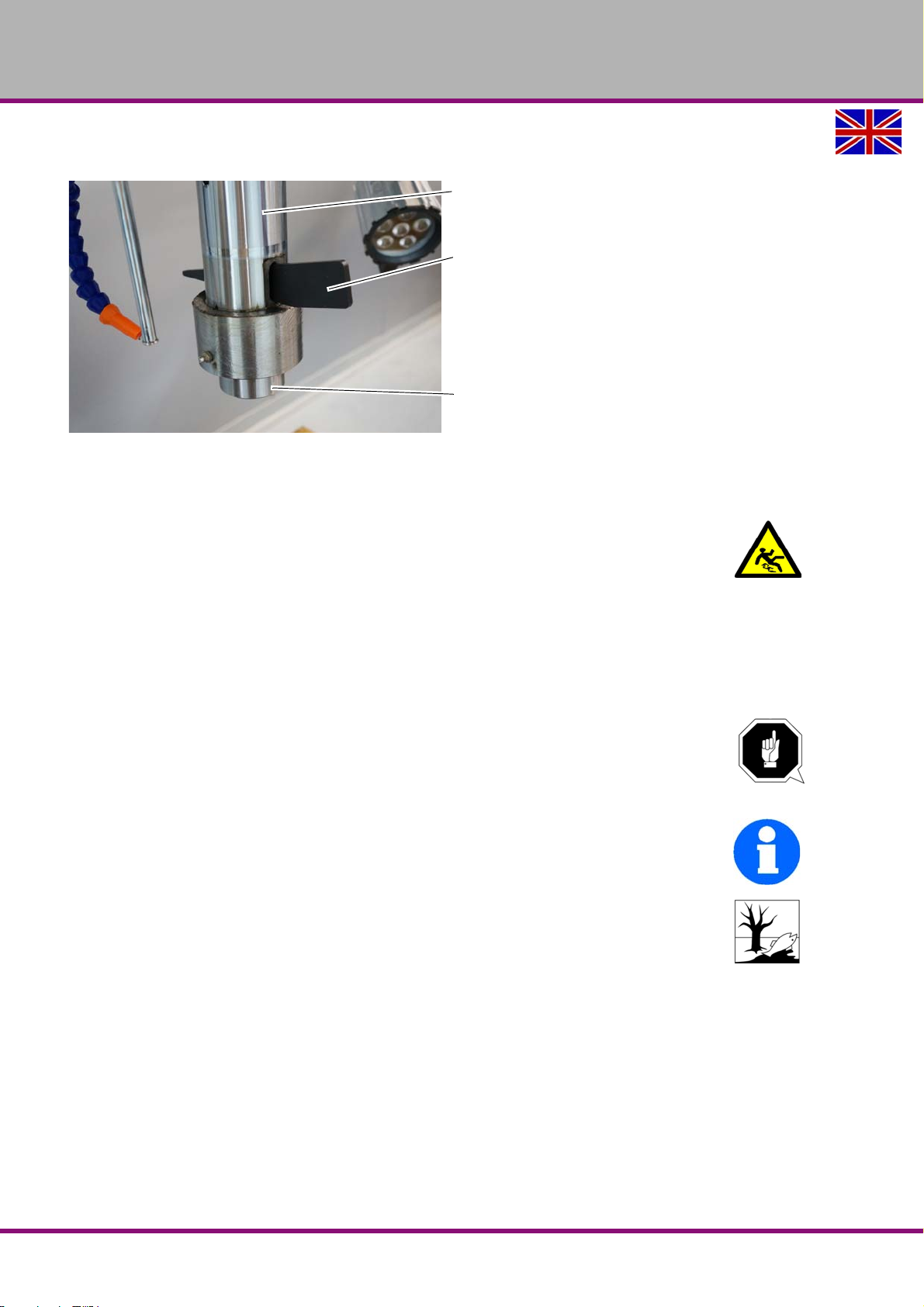
OPTIMUM
Spindle sleeve
Drill drift
Spindle
MASCHINEN - GERMANY
Put the ejection wedge into the ejection opening and hit with a hammer onto the ejection
wedge. Hold the tool firmly when doing this.
Img.4-7: Eject the drill bit or drilling chuck
4.13 Coolant equipment
WARNING!
Ejection and overflowing of coolants and lubricants. Make sure you do not get the
cooling lubricants on the floor. Cooling agents spilled on the floor must be removed
immediately.
Due to friction heat caused by the rotation movement high temperatures are generated on the
cutting edge of the tool.
Cool down the tool while drilling. In this way you attain better working results and a longer durability of the tools.
Adjust the flow using the shut-off and dosing tap.
ATTENTION!
Destruction of the pump due to dry running.
The pump is lubricated by the cooling agent. Do not operate the pump without coolant.
INFORMATION
Use a water-soluble and non-pollutant drilling emulsion as a cooling agent. This can be
acquired from authorised distributors.
Make sure that the cooling agent is being collected.
Respect the environment when disposing of lubricants and coolants.
Follow the manufacturer’s disposal instructions.
RD5GB
Version 1.0 2017-03-13Page 42 Original operating instructions
Operation
Page 43
OPTIMUM
MASCHINEN - GERMANY
5 Maintenance
In this chapter you will find important information about
Inspection
Maintenance
Repair
ATTENTION!
Properly performed regular maintenance is an essential prerequisite for
operational safety,
failure-free operation,
long service life of the machine and
the quality of the products that you manufacture.
Installations and equipment from other manufacturers must also be in good order and condition.
ENVIRONMENTAL PROTECTION
During work on the spindle head, please make sure that
collecting containers with sufficient capacity for the amount of liquid to be collected
are used.
liquids and oils should not be split on the ground.
Clean up any spilt liquid or oils immediately using proper oil-absorption methods and dispose of
them in accordance with current legal requirements on the environment.
Collect leakages
Do not re-introduce liquids spilt outside the system during repair or as a result of leakage from
the reserve tank; collect them in a collecting container for disposal.
Disposal
Never dump oil or other environmentally hazardous substances which are harmful to the environment in water inlets, rivers or channels.
Used oils must be delivered to a collection centre. Please consult your supervisor for further
information on your nearest collection point.
5.1 Safety
WARNING!
The consequences of incorrect maintenance and repair work may include:
very serious injury to personnel working on the machine,
Damages to the machine.
Only qualified personnel should carry out maintenance and repair work on th e machine.
5.1.1 Preparation
WARNING!
Only carry out work on the machine if it has been unplugged from the mains power
supply.
Attach a warning sign which secures against unauthorised switching on.
5.1.2 Restarting
Before restarting, run a safety check.
"Safety check“ on page 13
Maintenance
Version 1.0 2017-03-13 Page 43Original operating instructions
RD5 GB
Page 44
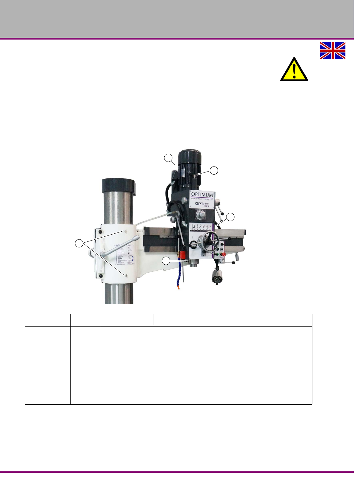
OPTIMUM
1
2
3
4
5
MASCHINEN - GERMANY
WARNING!
Before starting the machine you must be sure that
no dangers are generated for persons,
the machine is not damaged.
5.2 Inspection and maintenance
The type and level of wear depends to a large extent on the individual usage and operating
conditions. Any indicated intervals therefore are only valid for the corresponding approved conditions.
5.3 Overview of lubrication points
"Technical specification“ on page 20
Interval Where? What? How?
Examination for outside damages.
"Safety check“ on page 13
RD5
After each
Start of shift
maintenance or repair work
RD5GB
Repair
Maintenance
Version 1.0 2017-03-13Page 44 Original operating instructions
Page 45
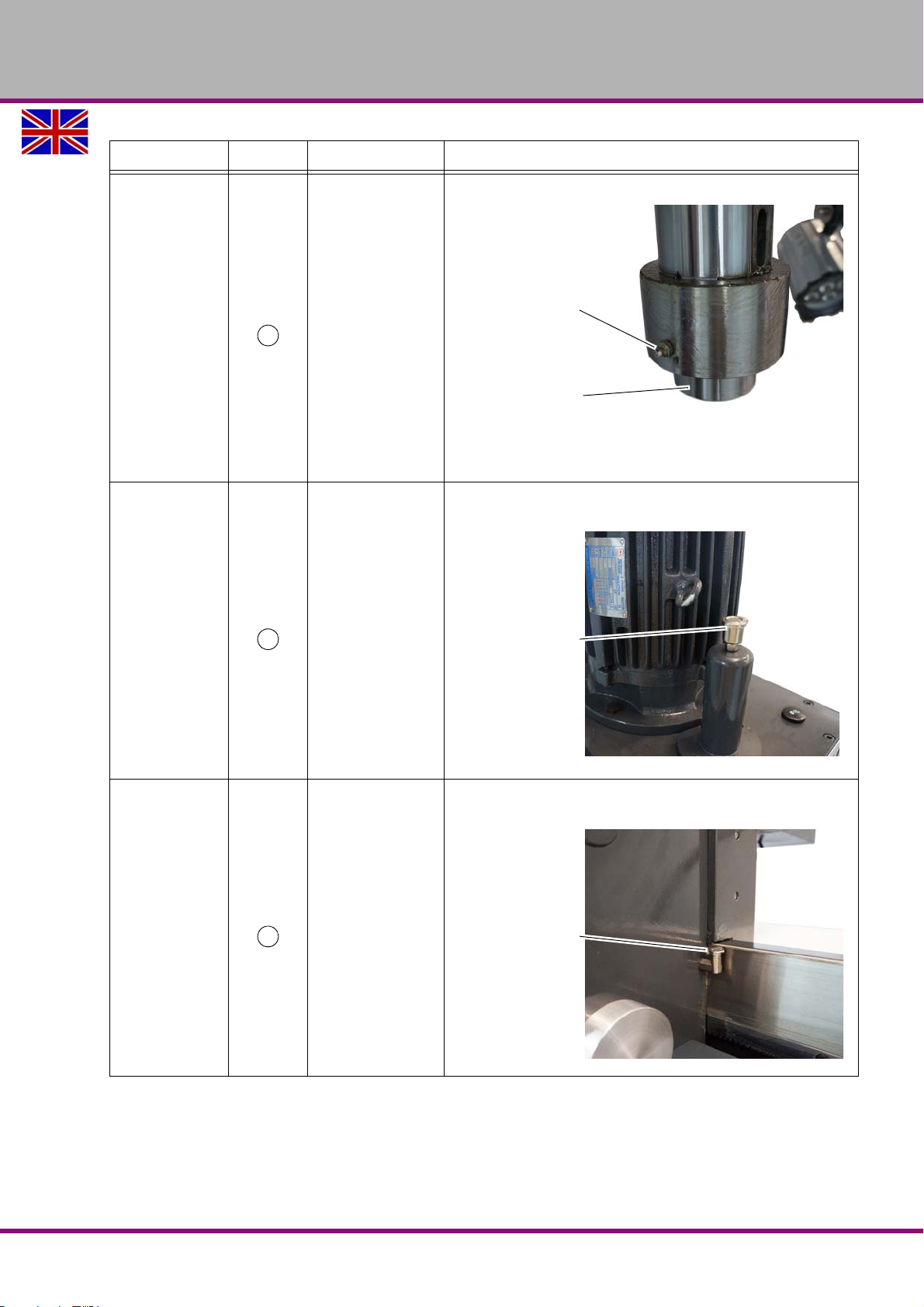
Interval Where? What? How?
1
Spindle grease nipple
Spindle
2
Top of gearbox oiler
3
Right of gearbox oiler
Greasethe spindle once a day with Mobil Greaserex
Lubricating
every day
47 with one stroke of the grease press.
Top front of gearbox. Oil once a day until it is com-
pletely filled with Mobilgear 626 oil.
OPTIMUM
MASCHINEN - GERMANY
every day
every day
Oiling
Oil right side of gearbox once a day until it is com-
pletely filled with Mobilgear 626 oil.
Oiling
Maintenance
Version 1.0 2017-03-13 Page 45Original operating instructions
RD5 GB
Page 46
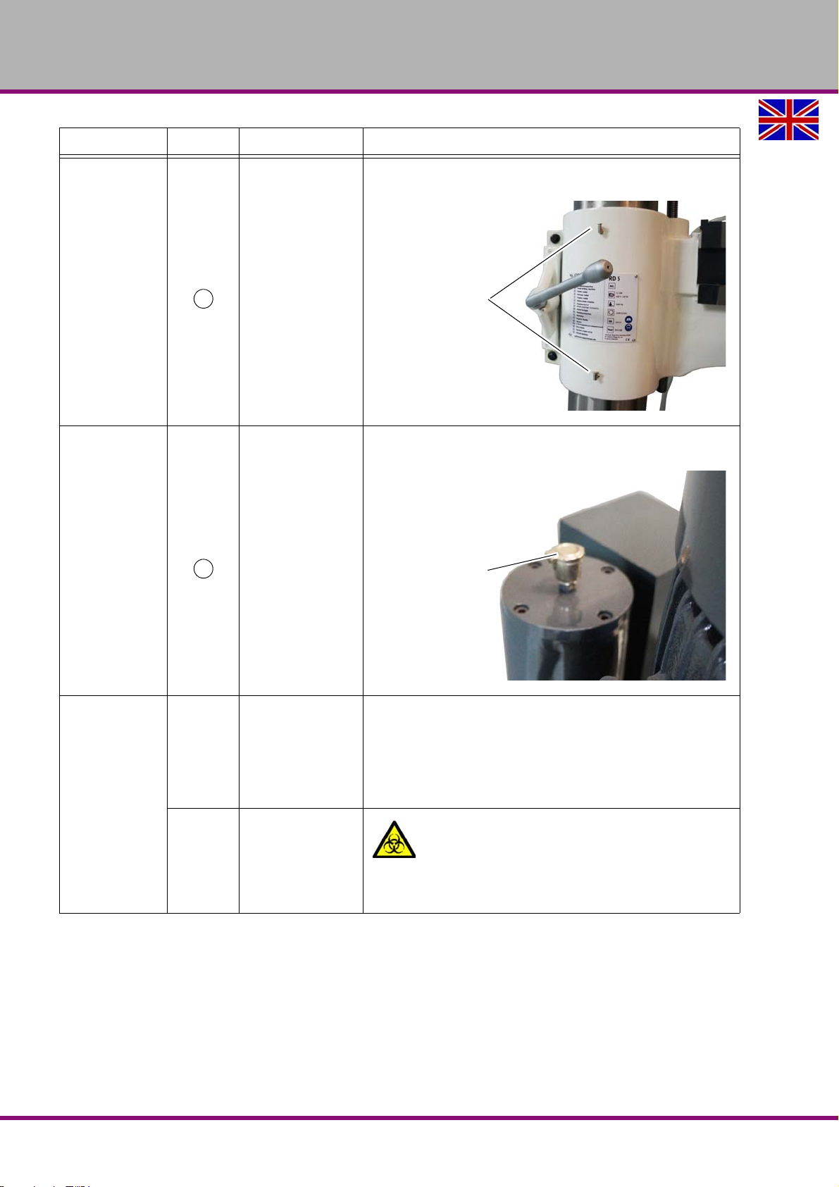
OPTIMUM
4
Oiler on column
5
Top of gearbox oiler
MASCHINEN - GERMANY
Interval Where? What? How?
Oil column once a day until it is completely filled with
Mobilgear 626 oil.
Oiling
every day
Oil top rear of gearbox once a week until it is com-
pletely filled with Mobilgear 626 oil.
Weekly
Weekly
Oiling
Lubricating
Bare steel parts
Inspection
Coolant tank
Rub bare steel parts with an acid-free lubricating oil,
e.g. Mobilgear 626 or engine oil.
CAUTION !
The cooling lubricant needs to be checked at
least weekly, including during downtimes,
with regard to its concentration, ph-value,
bacteria and fungal decay.
RD5GB
Maintenance
Version 1.0 2017-03-13Page 46 Original operating instructions
Page 47
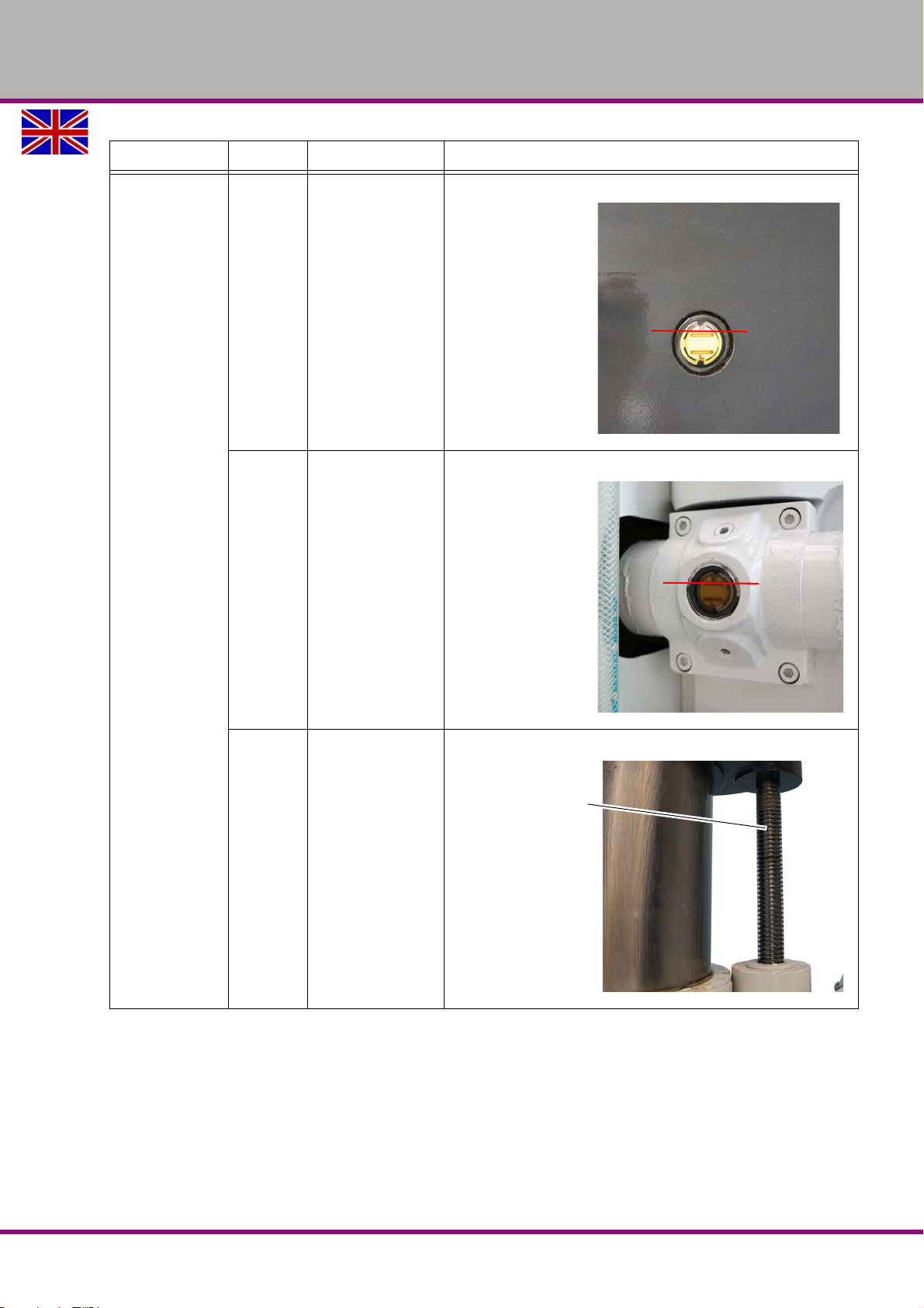
Interval Where? What? How?
Max. fill level
Max. fill level
Spindle
Check oil level,
Visual inspection
Oil sight glass spindle gear
Check oil level,
OPTIMUM
MASCHINEN - GERMANY
Every month
Cantilever
Lifting device
Oil sight glass gear
Spindle
Cantilever
Lifting device
Visual inspection
Lubricate with greaseMobil Greaserex 47.
Lubricate
Maintenance
Version 1.0 2017-03-13 Page 47Original operating instructions
RD5 GB
Page 48
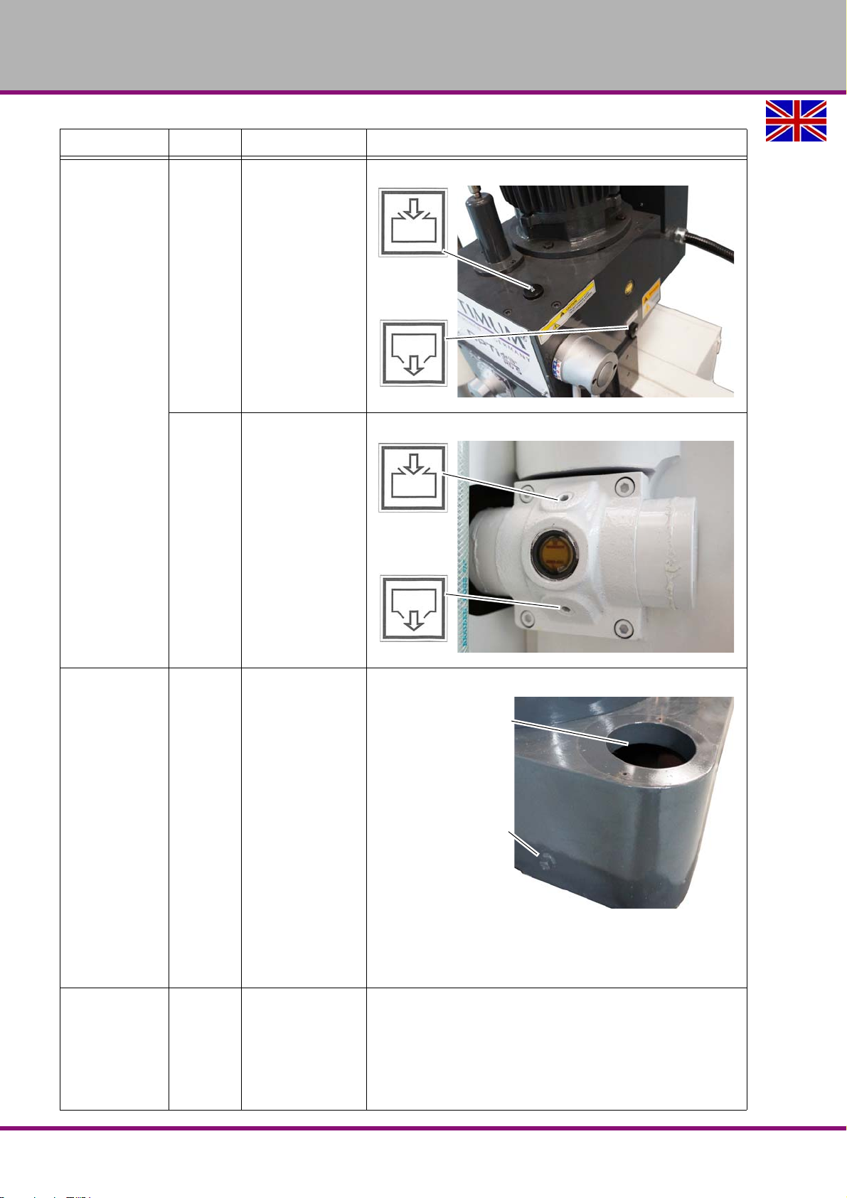
OPTIMUM
Cleaning opening
Drain screw
MASCHINEN - GERMANY
Interval Where? What? How?
Change the oil on the spindle gearbox.
Oil change
Spindle gear
annually
at least annually
Gear
Lifting device
Change the oil on the lifting device of the cantilever.
Oil change
Cantilever
Replacing
Cleaning
Disinfect
after 3
RD5GB
Cooling lubricant system
"Cooling lubricants and tanks“ on page 52
"Inspection plan for water-mixed cooling lubricants“
on page 53
The spindle must not start when the clamping lever is
in a released position.
Check and adjust
switching point
to 5 years
Column
Clamping lever
Positions switch
"Adjustment of position switch on clamping lever“ on
page 50
Maintenance
Version 1.0 2017-03-13Page 48 Original operating instructions
Page 49
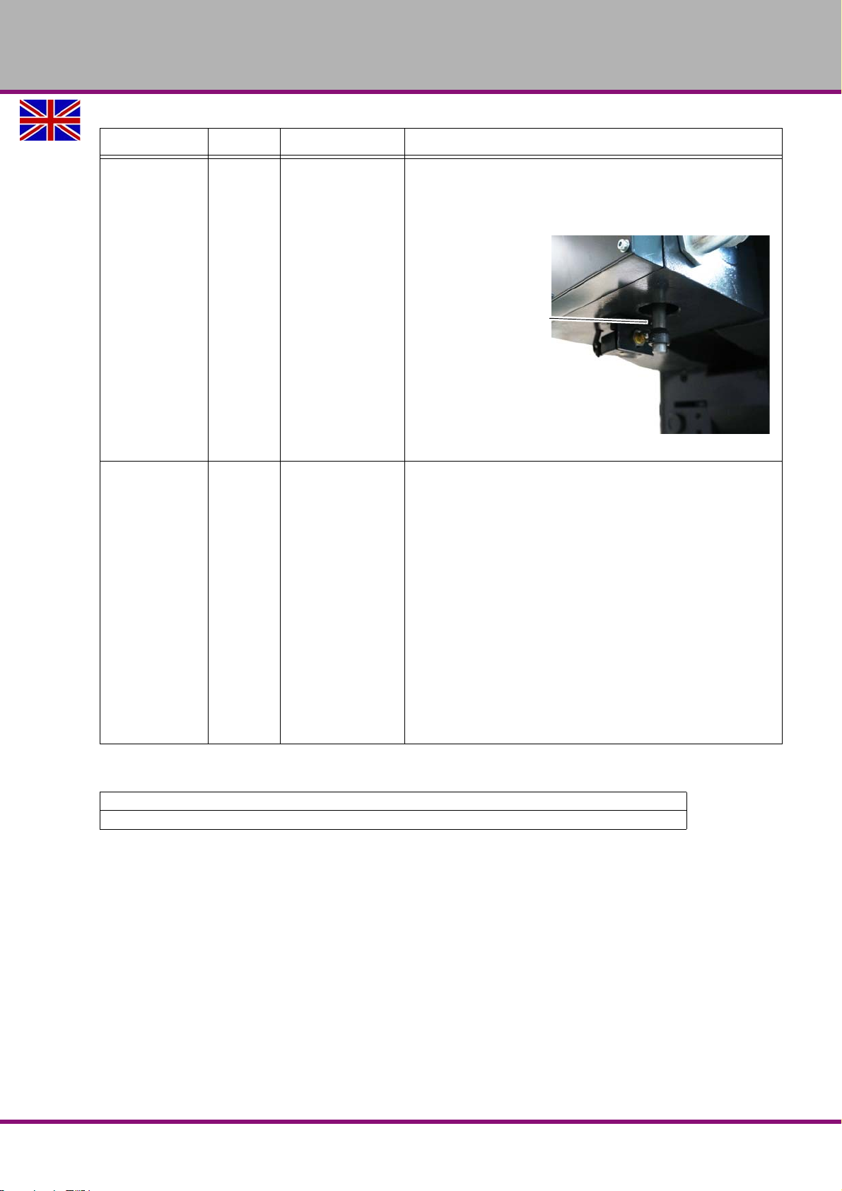
Interval Where? What? How?
Positions switch
The service life of the position switch of the spindle position may have been reached due to the operating conditions. Replacement is recommended to ensure further
safe and fault-free operation.
Replace the posi-
after 4,
tion switch.
OPTIMUM
MASCHINEN - GERMANY
based on operator's
empirical values
at the latest 5 years
in accordance with German DGUV (BGV A3)
Positions switch
Spindle contracted, extended
"Obligations of the operating company“ on page 12
"Electronics“ on page 19
Electrical inspection
Electronics
5.4 Recommended wear and tear parts
Extendable shift rod - item number circuit diagram B1
Position switch with spindle sleeve contracted, spindle sleeve extended circuit diagram B2
5.5 Adjustment of clearance on cantilever and drilling head
If needed, reduce the guide clearance between the cantilever arm and the drilling head.
Adjustment of vertical roll guidance:
Remove cover plate.
Undo screws (1).
Undo clamping screw at (2) with an Allen key, and turn the ring (2) with a suitable tool in the
hole.
Clamp the screws (1) again and check the free running of the drilling head with the hand
wheel using the entire travel on the cantilever.
Adjustment of horizontal roll guidance:
Undo screws (3):
Maintenance
Version 1.0 2017-03-13 Page 49Original operating instructions
RD5 GB
Page 50
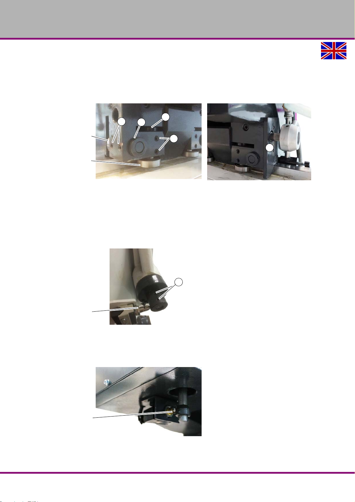
OPTIMUM
Vertical roll guidance
Horizontal roll guidance
6
2
1
4
3
Positions switch
1
Positions switch
MASCHINEN - GERMANY
Undo clamping screw at (4) with an Allen key, and turn the ring (4) with a suitable tool in the
hole.
Clamp the screws (3) again and check the free running of the drilling head with the hand
wheel using the entire travel on the cantilever.
Undertake the working steps on the other side (6) precisely in that way. The clamping lever
must be removed to be able to remove the cover plate (6).
Img.5-1: Guide for drilling head on cantilever
5.6 Adjustment of position switch on clamping lever
The clamping lever must be pulled firmly, so that the spindle drive switches on.
If the spindle no longer turns, or the spindle rotation does not shut down if the clamping lever is
released.
Undo the stud bolts (1) on the eccentric cam and turn the eccentric cam until the switching
point is correctly set.
Img.5-2: Switching point of clamping lever
5.7 Adjustment of the position switch spindle sleeve
The spindle drive must be shut down if the drilling spindle sleeve is completely contracted or
completely extended.
RD5GB
Img.5-3: Switching point of drilling spindle sleeve
Maintenance
Version 1.0 2017-03-13Page 50 Original operating instructions
Page 51

OPTIMUM
MASCHINEN - GERMANY
5.8 Repair
5.8.1 Customer service technician
For any repair work, request the assistance of an authorised customer service technician. Contact your specialist dealer if you do not have customer service information or contact Stürmer
Maschinen GmbH in Germany who can provide you with a specialist dealer's contact information. Optionally, the company Stürmer Maschinen GmbH ; Dr.-Robert-Pfleger-Str. 26 ; D- 96103
Hallstadt can provide a customer service technician, however, the request for a customer service technician can only be made via your specialist dealer.
If the repairs are carried out by qualified technical personnel, they must follow the indications
given in these operating instructions.
Optimum Maschinen Germany GmbH accepts no liability nor does it guarantee against damage
and operating malfunctions resulting from failure to observe these operating instructions.
For repairs, only use
faultless and suitable tools,
original parts or parts from series expressly authorised by Optimum Maschinen Germany
GmbH.
Maintenance
Version 1.0 2017-03-13 Page 51Original operating instructions
RD5 GB
Page 52
OPTIMUM
MASCHINEN - GERMANY
5.9 Cooling lubricants and tanks
CAUTION!
The cooling lubricant can cause diseases. Avoid direct contact with cooling lubricant or
parts covered in cooling lubricant.
Cooling lubricant circuits and tanks for water-cooling lubricant mixtures must be completely
emptied, cleaned and disinfected as needed, but at least once per year or every time the cooling lubricant is replaced.
If fine chips and other foreign matters are accumulated in the coolant tank, the machine can no
longer be correctly supplied with coolant. Furthermore, the lifetime of the coolant pump is
reduced.
When processing cast iron or similar materials generating fine chips, cleaning the coolant tank
more often is recommended.
Limit values
The cooling lubricant must be replaced, the cooling lubricant circuit and tank emptied,
cleaned and disinfected if
the pH value drops by more than 1 based on the value during initial filling. The maximum
permissible pH value during initial filing is 9.3
there is a perceivable change in the appearance, odour, floating oil or increase of the bacte-
ria to more than 10/6/ml
there is an increase in nitrite content to more than 20 ppm (mg/1) or nitrate content to more
than 50 ppm (mg/1)
there is an increase in the N-nitrosodiethanolamine (NDELA) to more than 5 ppm (mg/a)
CAUTION!
Comply with the manufacturer's specifications for mixture rat ios, hazardous substances,
e.g. system cleaners, including their permissible minimum use times.
CAUTION!
Since the cooling lubricant escapes under high pressure, pumping out the coolant by
using the existing cooling lubricant pump via a pressure hose into a suitable tank is not
recommended.
ENVIRONMENTAL PROTECTION
During work on the cooling lubricant equipment please make sure that
collector tanks are used with sufficient capacity for the amount of liquid to be col-
lected.
liquids and oils should not be spilled on the ground.
Clean up any spilled liquid or oils immediately using proper oil-absorption methods and dispose of them in accordance with current statutory environmental regulations.
Collect leakages
Do not re-introduce liquids spilled outside the system during repair or as a result of leakage
from the reserve tank, instead collect them in a collecting container for disposal.
Disposal
Never dump oil or other substances which are harmful to the environment into water inlets, rivers or channels. Used oils must be delivered to a collection centre. Consult your supervisor if
you do not know where the collection centre is.
Coolant lubricatingEN
Version 1.0 dated 2017-03-13Page 52 Original operating instructions
coolant_GB.fm
Page 53

5.9.1 Inspection plan for water-mixed cooling lubricants
Company:
No.:
Date:
used cooling lubricant
OPTIMUM
MASCHINEN - GERMANY
size to be checked Inspection methods Inspection
intervals
noticeable
changes
pH value Laboratory techniques
Usage concentration Manual refractometer
Base reserve Acid titration in accordance
Nitrite content Test sticks method or labora-
Nitrate/nitrite content
of the preparation water, if
this is not removed from
the public
grid
Appearance, odour daily Find and rectify causes,
1)
electrometric with pH meter
(DIN 51369)
Local measurement method:
with pH paper
(Special indicators with
suitable measuring range)
with
Manufacturer's recommendation
tory method
Test sticks method or laboratory method
weekly
1)
weekly
as required Method is independent of tramp oil content
1)
weekly
as required Use water from the public grid if there is
Procedure and comment
e.g. skim off oil, check filter, ventilate cooling
lubricant system
if pH value decreases
> 0.5 based on initial filing:
Measures in accordance manufacturer's recommendations
> 1.0 based on initial filing:
Replace cooling lubricant, clean cooling lubricant circulation system
Method results in incorrect values with tramp
oil content
> 20 mg/L nitrite:
Replace cooling lubricant or part
or inhibiting additives;
otherwise NDELA (N-nitrosodiethanolamine)
in the cooling lubricant system and in the air
must be determined
> 5 mg/L NDELA in the cooling lubricant system:
Replacement,
clean and disinfect cooling lubricant circulation system, find nitrite source and, if possible, rectify.
water from the pubic grid has
> 50 mg/l nitrate: Inform the waterworks
1)
The specified inspection intervals (frequency) are based on continuous operation. Other operational
conditions can result in other inspection intervals; exceptions are possible in accordance with Sections 4.4
and 4.10 of the TGS 611.
Editor:
Signature:
coolant_GB.fm
Version 1.0 dated 2017-03-13 Page 53Original operating instructions
Coolant lubricating EN
Page 54

OPTIMUM
MASCHINEN - GERMANY
coolant_GB.fm
Coolant lubricatingEN
Version 1.0 dated 2017-03-13Page 54 Original operating instructions
Page 55
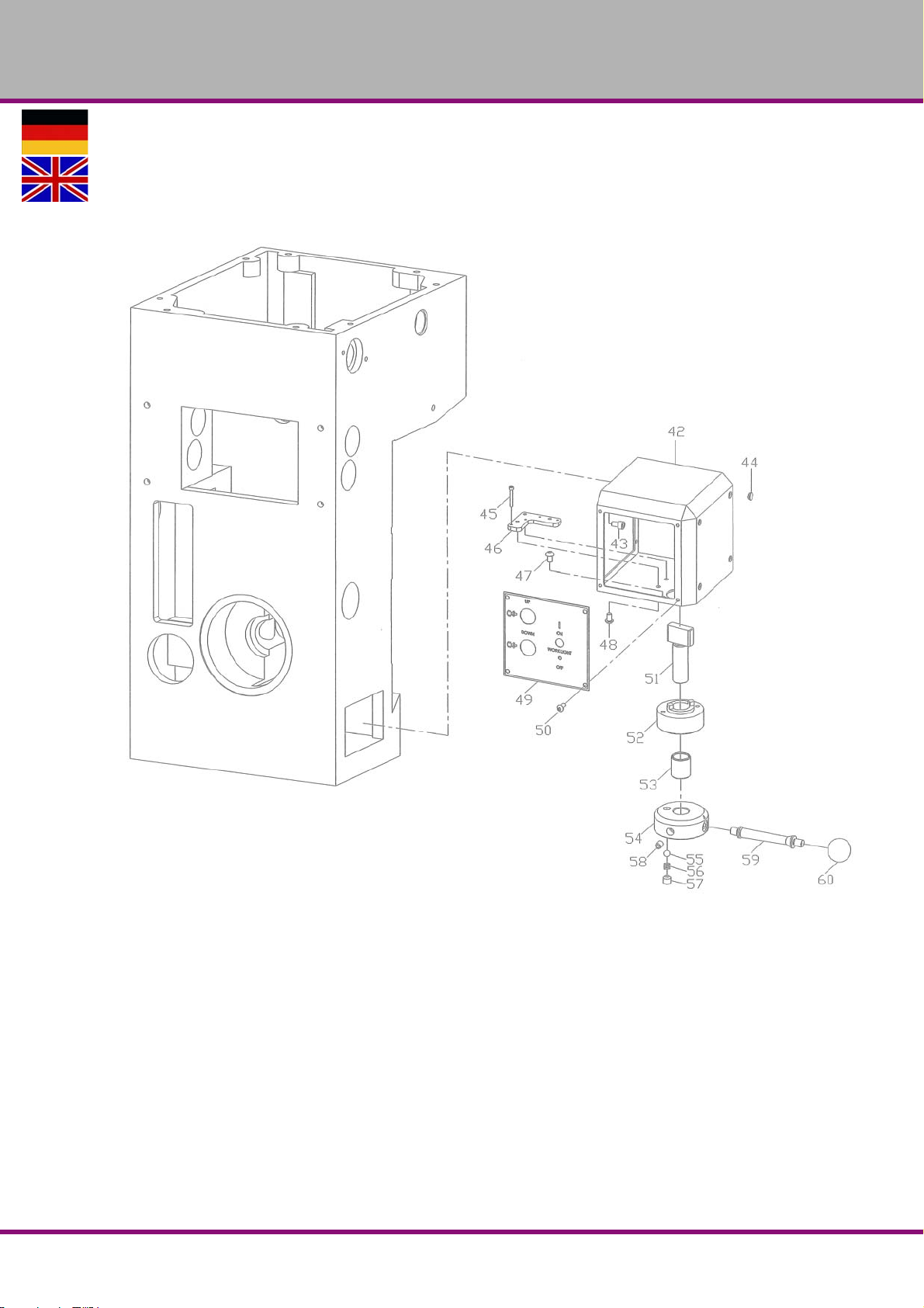
6 Ersatzteile - Spare parts
6.1 Bohrkopf - Drilling head
OPTIMUM
MASCHINEN - GERMANY
Ersatzteile - Spare parts
Version 1.0 2017-03-13 55Originalbetriebsanleitung
RD5 DE
Page 56
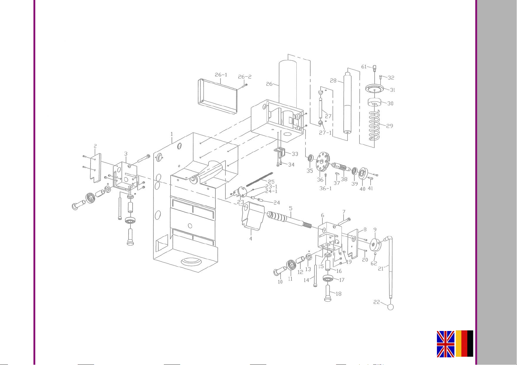
6.2 Getriebe Bohrkopf Rückseite - Gear of drilling head rear
RD5DE
MASCHINEN - GERMANY
OPTIMUM
Version 1.0 2017-03-1356 Originalbetriebsanleitung
Ersatzteile - Spare parts
Page 57
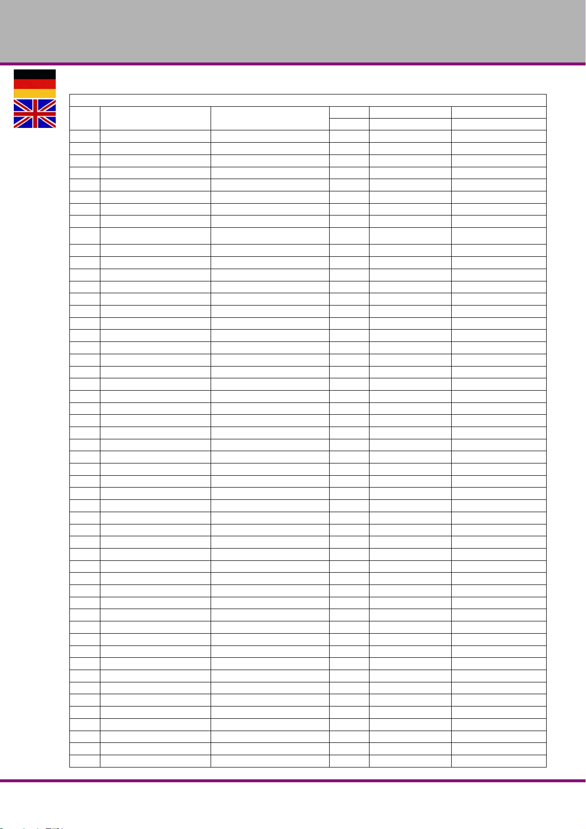
OPTIMUM
MASCHINEN - GERMANY
Ersatzteilliste - Spare part list - Bohrkopf Rückseite - Drilling head
Pos.
Bezeichnung Designation
1 Getriebegehäuse Gear Box 1 030490500101
2 Aluminiumplatte Aluminium Plate 1 030490500102
3 Lagerbock Bearing bracket 1 030490500103
4 Excenter Eccentric 1 030490500104
5 Klemmnockenwelle Clamping Cam Shaft 1 030490500105
6 Lagerbock Bearing bracket 1 030490500106
7 Schraube Bolt 2 M10x85
8 Aluminiumplatte Aluminium Plate 1 030490500108
9
10 Exzentrische Welle Eccentric Shaft 2 030490500110
11 Lager Bearing 2 6205ZZ 0406205ZZ
12 Stange Rod 2 030490500112
13 Einstellscheibe Adjusting Washer 2 030490500113
14 Schraube Bolt 2 M10x10
15 Einstellscheibe Adjusting Washer 2 030490500115
16 Stange Rod 2 030490500116
17 Lager Bearing 2 6205ZZ 0406205ZZ
18 Exzentrische Welle Eccentric Shaft 2 030490500118
19 Schraube Bolt 8 M10x10
20 Schraube Bolt 4 030490500120
21 Klemmhebel Clamping Lever 1 030490500121
22 Kugel Ball 1 1/2" 030490500122
23 Exzentrische Welle Eccentric Shaft 1 030490500123
23-1 Schraube Bolt 1 M4x60
24 Welle Shaft 1 030490500124
24-1 Lager Innenring Bearing Inner Ring 1 IRT1015-1 0304905001241
25 Kette Chain 1 030490500125
26 Federgehäuse Spring Housing 1 030490500126
26-1 Aluminiumplatte Aluminium Plate 1 0304905001261
26-2 Schraube Bolt 4 M5x35
27 Einstellbare Schaltwelle Adjustable Shaft of Switch 1 030490500127
27-1 Einstellbare Welle der Buchse Adjustable Shaft of Bushing 2 0304905001271
28 Welle Spring Shaft 1 030490500128
29 Feder Spring 1 030490500129
30 Mutter Nut 1 030490500130
31 Abdeckung Cover 1 030490500131
32 Schraube Bolt 4 M6x14
33 Montageplatte Mounting Plate 1 030490500133
34 Schraube Bolt 2 M6x12
35 Lager Bearing 1 6202ZZ 040602ZZ
36 Scheibe Pulley 1 030490500136
36-1 Adapter Kette Adapter of Chain 1 0304905001361
37 Passfeder Key 1 7x20 030490500137
38 Welle Shaft 1 030490500138
39 Lager Bearing 1 6202ZZ 040620ZZ
40 Lagerdeckel Bearing Cover 1 030490500140
41 Schraube Bolt 2 M6x20
42 Bedienpanel Operating Box 1 030490500142
43 Schraube Bolt 4 M6x10
44 Verschlussstopfen Hole Plug 4 030490500144
45 Schraube Bolt 2 M3x25
46 Montageplatte Mounting Plate 1 030490500146
Wahlschalter Vorschubge-
schwindigkeit
Feed Speed Selector 1 030490500109
Menge Grösse Artikelnummer
Qty. Size Item no.
Ersatzteile - Spare parts
Version 1.0 2017-03-13 57Originalbetriebsanleitung
RD5 DE
Page 58
OPTIMUM
MASCHINEN - GERMANY
Ersatzteilliste - Spare part list - Bohrkopf Rückseite - Drilling head
Pos.
Bezeichnung Designation
47 Schraube Bolt 2 M6x10
48 Bolzen Bolt 3 030490500148
49 Schalterplatte Switch Plate 1 030490500149
50 Schraube Bolt 4 M5x12
51 Welle Shaft 1 030490500151
52 Festflansch Fixed Flange 1 030490500152
53 Lager dauergeschmiert Self-Lubricating Bearing 1 LFB2025 030490500153
54 Flansch Flange 1 030490500154
55 Stahlkugel Ball Steel 1 5/16" 030490500155
56 Feder Wire Spring 1 030490500156
57 Schraube Bolt 1 M10x10
58 Schraube Bolt 1 M8x10
59 Welle Shaft 1 030490500159
60 Kugel Ball 1 3/8" 030490500160
61 Schmieröler Cup Oil 1 030490500161
62 Schraube Bolt 1 M8x10
Menge Grösse Artikelnummer
Qty. Size Item no.
RD5DE
Ersatzteile - Spare parts
Version 1.0 2017-03-13 58 Originalbetriebsanleitung
Page 59
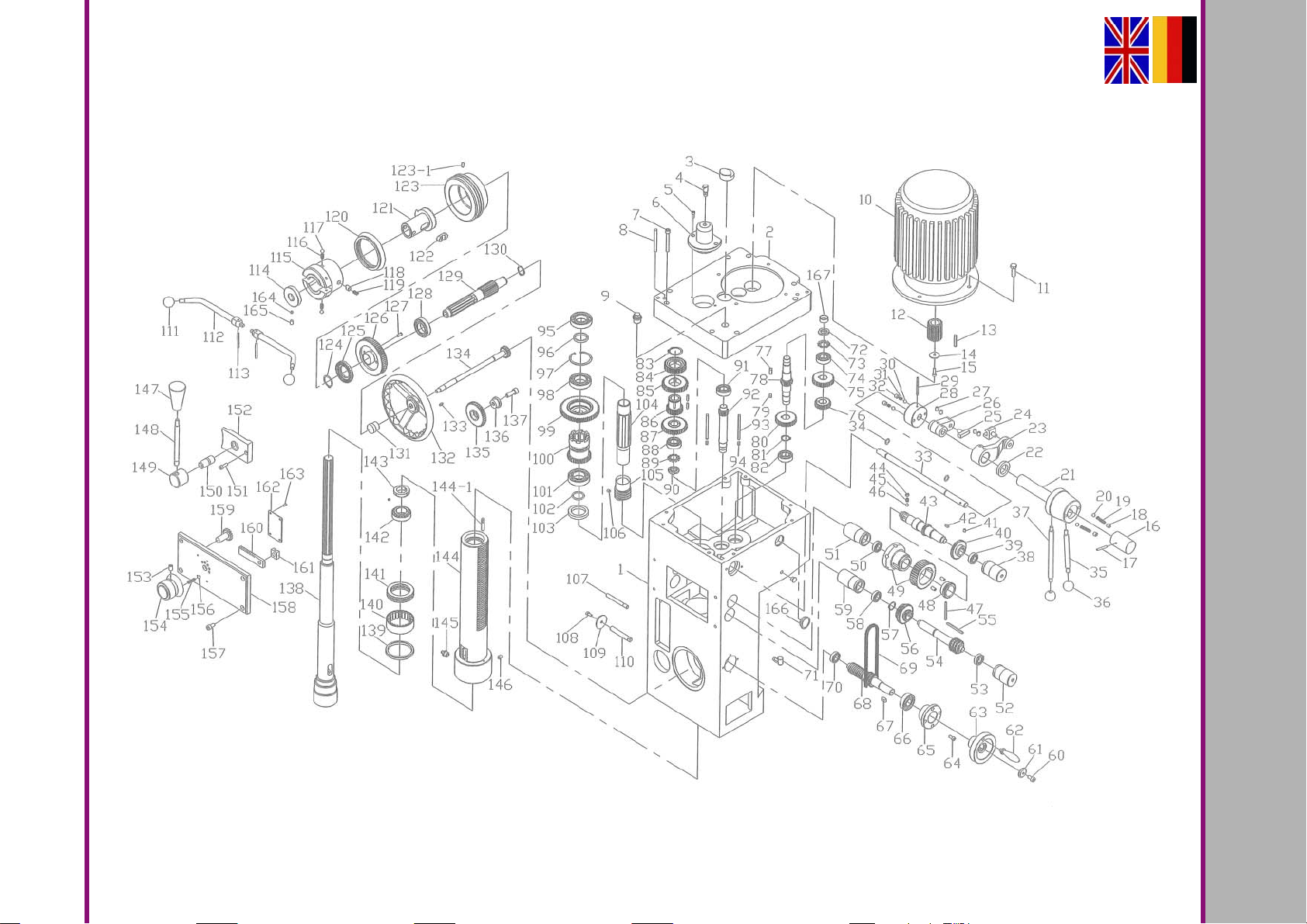
Ersatzteile - Spare parts
Version 1.0 2017-03-13 59Originalbetriebsanleitung
6.3 Getriebe Bohrkopf - Gear of drilling head
RD5 DE
MASCHINEN - GERMANY
OPTIMUM
Page 60

OPTIMUM
MASCHINEN - GERMANY
Ersatzteilliste - Spare part list - Getriebe Bohrkopf - Gear of drilling head
Pos.
Bezeichnung Designation
1 Getriebe Gear Box 1 030490500201
2 Getriebe Abdeckung Gear Box Cover 1 030490500202
3 Dichtung Gasket 1 030490500203
4 Schmiernippel Grease Nipple 1 PT1/8" 030490500204
5 Schraube Bolt 2 M6x14
6 Spindelabdeckung Spindle Cover 1 030490500206
7 Schraube Bolt 8 M8x65
8 Kegelstift Taper Pin 2 7x75 030490500208
9 Verschluss Plug 1 1/2" 030490500209
10 Motor Motor 1 030490500210
11 Schraube Bolt 4 M10x30
12 Motorzahnrad Motor Gear 1 030490500212
13 Passfeder Key 1 6x40 030490500213
14 Scheibe Washer 1 030490500214
15 Schraube Bolt 1 M6x20
16 Wahlhebel Geschwindigkeit Feed Speed Selector 1 030490500216
17 Federstift Spring Pin 1 5x40 030490500217
18 Schraube Bolt 2 M10x10
19 Feder Spring 2 030490500219
20 Stahlkugel Ball Steel 2 5/16" 030490500220
21 Welle Shaft 1 030490500221
22 Dichtung Oil Seal 1 30x45x8 030490500222
23 Schalthebel Switch lever 1 030490500223
24 Gabel Fork 1 030490500224
25 Platte Plate 1 030490500225
26 Schalthebel Switch lever 1 030490500226
27 Schraube Bolt 4 M8x12
28 Wahlhebel Geschwindigkeit Feed Speed Selector 1 030490500228
29 Federstift Spring Pin 1 5x60 030490500229
30 Stahlkugel Ball Steel 2 5/16" 030490500230
31 Feder Spring 2 030490500231
32 Schraube Bolt 2 M10x10
33 Spindel-Verstellwelle Spindle Change Shaft 1 030490500233
34 O-Ring O-Ring 2 12 030490500234
35 Hebel Lever 1 030490500235
36 Kugel Ball 2 3/8' 030490500236
37 Hebel Lever 1 030490500237
38 Buchse Bushing 1 030490500238
39 Lager Bearing 1 6002ZZ 0406002ZZ
40 Zahnrad Gear 1 030490500240
41 Schraube Bolt 1 M6x8
42 Passfeder Key 1 5x12 030490500242
43 Zahnwelle Gear Shaft 1 030490500243
44 Schraube Bolt 6 M10x6
45 Feder Spring 6 030490500245
46 Stahlkugel Ball Steel 6 5/16" 030490500246
47 Federstift Spring Pin 1 5x40 030490500247
48 Zahnrad Gear 1 030490500248
49 Schneckenrad kpl. Worm gear cpl. 1 030490500249
50 Lager Bearing 1 6002ZZ 0406002ZZ
51 Buchse Bushing 1 030490500251
52 Buchse Bushing 1 030490500252
Menge Grösse Artikelnummer
Qty. Size Item no.
RD5DE
Ersatzteile - Spare parts
Version 1.0 2017-03-13 60 Originalbetriebsanleitung
Page 61
OPTIMUM
MASCHINEN - GERMANY
Ersatzteilliste - Spare part list - Getriebe Bohrkopf - Gear of drilling head
Pos.
Bezeichnung Designation
53 Lager Bearing 1 6002Z 0406002Z
54 Zahnwelle Gear shaft 1 030490500254
55 Passfeder Key 1 5x65 030490500255
56 Zahnrad Gear 1 030490500256
57 Sicherungsring Retainer 1 22 030490500257
58 Lager Bearing 1 030490500258
59 Buchse Bushing 1 030490500259
60 Schraube Bolt 1 M6x12
61 Scheibe Washer 1 030490500261
62 Welle Shaft 1 3/8" 030490500262
63 Griff Handle 1 030490500263
64 Schraube Bolt 4 M6x14
65 Buchse Bushing 1 030490500265
66 Lager Bearing 1 6204Z 0406204Z
67 Passfeder Key 1 6x12 0304905002
68 Welle Shaft 1 030490500268
69 Kette Chain 3 0304905002
70 Lager Bearing 1 6002ZZ 0406002ZZ
71 Schmieröler Cup Oil 1 1/8" 030490500271
72 Klemmmutter Lock Nut 1 030490500272
73 Zahnscheibe Crown Washer 1 AW04 030490500273
74 Lager Bearing 1 6004ZZ 0406004ZZ
75 Zahnrad Gear 1 030490500275
76 Zahnrad Gear 1 030490500276
77 Passfeder Key 1 7x20 030490500277
78 Zahnwelle Gear Shaft 1 030490500278
79 Passfeder Key 1 7x12 030490500279
80 Zahnrad Gear 1 030490500280
81 Sicherungsring Retainer 1 22 030490500281
82 Lager Bearing 1 6004ZZ 0406004ZZ
83 Sicherungsring Retainer 1 35 030490500283
84 Zahnrad Gear 1 030490500284
85 Zahnrad Gear 1 030490500285
86 Zahnrad Gear 1 030490500286
87 Zahnrad Gear 1 030490500287
88 Kugellager Bearing 1 6004ZZ 0406004ZZ
89 Zahnscheibe Crown Washer 1 AW04 030490500289
90 Klemmmutter Lock Nut 1 030490500290
91 Lager Bearing 1 6004ZZ 0406004ZZ
92 Zahnwelle Gear Shaft 1 030490500292
93 Passfeder Key 2 6x85 030490500293
94 Passfeder Key 2 6x10 030490500294
95 Kugellager Bearing 1 6007ZZ 0406007ZZ
96 Scheibe Washer 1 030490500296
97 Sicherungsring Retainer 1 030490500297
98 Kugellager Bearing 1 6007ZZ 0406007ZZ
99 Kupplungsteil Getriebe oben Clutch Upper Gear 1 030490500299
100 Kupplungsteil Getriebe unten Clutch Lower Gear 1 0304905002100
101 Lager Bearing 1 6007 0406007
102 O-Ring O-Ring 1 P30 0304905002102
103 Dichtung Oil Seal 1 42x58x8 0304905002103
104 Spindelwelle Spindle Shaft 1 0304905002104
105 Schnecke Worm 1 0304905002105
Menge Grösse Artikelnummer
Qty. Size Item no.
Ersatzteile - Spare parts
Version 1.0 2017-03-13 61Originalbetriebsanleitung
RD5 DE
Page 62
OPTIMUM
MASCHINEN - GERMANY
Ersatzteilliste - Spare part list - Getriebe Bohrkopf - Gear of drilling head
Pos.
Bezeichnung Designation
106 Schraube Bolt 1 M6x6
107 feste Sperre Fixed Lock 1 0304905002107
108 Schraube Bolt 1 0304905002108
109 Scheibe Washer 1 0304905002109
110 Kupfer Passfeder Copper Key 1 0304905002110
111 Kugel Ball 2 3/8" 0304905002111
112 Vorschubgriff Feed Handle 2 0304905002112
113 Federstift Spring Pin 2 5x50 0304905002113
114 Mutter Nut 1 0304905002114
115 Kupplungsgehäuse Clutch Housing 1 0304905002115
116 Feder Spring 2 0304905002116
117 Stahlkugel Ball Steel 2 3/8" 0304905002117
118 Splint Cotter Pin 1 0304905002118
Menge Grösse Artikelnummer
Qty. Size Item no.
RD5DE
Ersatzteile - Spare parts
Version 1.0 2017-03-13 62 Originalbetriebsanleitung
Page 63
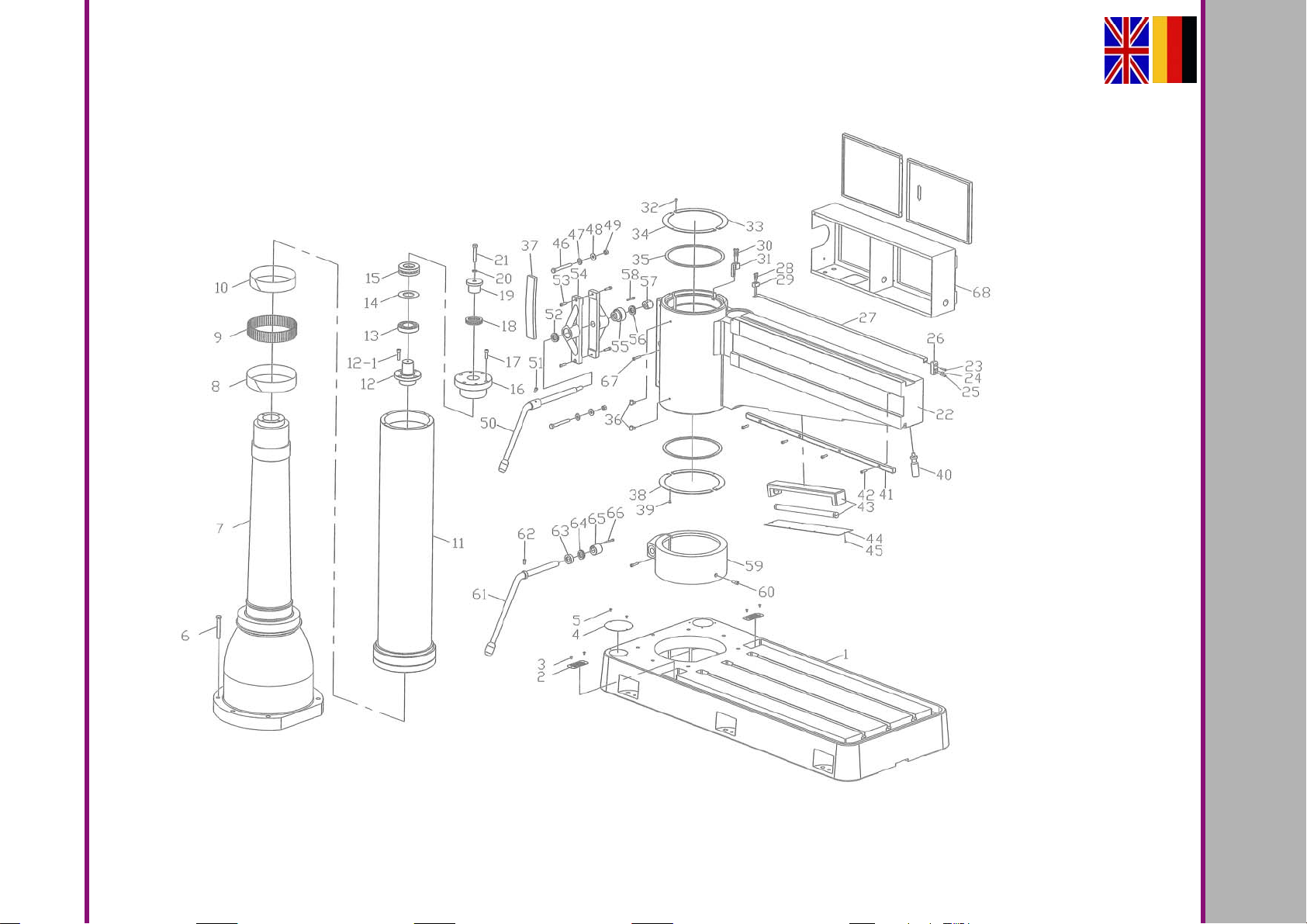
Ersatzteile - Spare parts
Version 1.0 2017-03-13 63Originalbetriebsanleitung
6.4 Säule - Column
RD5 DE
MASCHINEN - GERMANY
OPTIMUM
Page 64

OPTIMUM
MASCHINEN - GERMANY
Ersatzteilliste - Spare part list - Säule - Column
Pos.
Bezeichnung Designation
1 Maschinenfuss Base ] 030490500301
2 Filtersieb Filter Screen 2 030490500302
3 Bolzen Bolt 4 030490500303
4 Abdeckung Cover 1 030490500304
5 Schraube Bolt 2 030490500305
6 Schraube Bolt 7 030490500306
7 Innere Säule Internal Column 1 030490500307
8 Stahlband Steel Band 1 030490500308
9 Nadel Needle 80 030490500309
10 Stahlband Steel Band 1 030490500310
11 Stahlband Steel Band 1 030490500311
12 Lagerabdeckung oben Bearing cover of the top 1 030490500312
12-1 Schraube Bolt 4 M10x40
13 Lager Bearing 1 6211 0406211
14 Scheibe Washer 1 030490500314
15 Lager Bearing 1 3911 0403911
16 Feste Lagerabdeckung Fixed Bearing Cover 1 030490500316
17 Schraube Bolt 4 030490500317
18 Lager Bearing 1 51111 04051111
19 Lagerabdeckung oben Bearing cover of the top 1 030490500319
20 Federring Spring Washer 1 1/2" 030490500320
21 Schraube Bolt 1 030490500321
22 Arm Arm 1 030490500322
23 Schraube Bolt 2 M6x25
24 Schraube Bolt 2 M8x12
25 Schraube Bolt 1 M6x25
26 fester Flansch Fixed Flange 1 030490500326
27 Stahlband Steel Band 1 030490500327
28 Schraube Bolt 2 M6x20
29 fester Flansch Fixed Flange 1 030490500329
30 Schraube Bolt 2 M6x30
31 Passfeder Key 1 030490500331
32 Schraube Bolt 6 M6x10
33 Abdeckung Compressing Cover 1 030490500333
34 Abdeckung Compressing Cover 1 030490500334
35 Staubdichtung Dust Seal 2 5 030490500335
36 Schmieröler Cup Oil 2 PTl/8" 030490500336
37 Staubdichtung Dust Seal 1 12 030490500337
38 Abdeckung Compressing Cover 2 030490500338
39 Schraube Bolt 6 M6x10
40 Griff Handle 1 030490500340
41 Zahnstange Arm Rack 1 030490500341
42 Schraube Bolt 4 M3x30
43 Lampe Lamp 1 030490500343
44 Acrylabdeckung Acrylic Cover 1 030490500344
45 Schraube Bolt 12 030490500345
46 Schraube Bolt 2 030490500346
47 Scheibe Washer 2 030490500347
48 Scheibe Washer 2 030490500348
49 Mutter Nut 2 1/2" 030490500349
50 Hebel Lever 1 030490500350
51 Schraube Bolt 1 M8x16
Menge Grösse Artikelnummer
Qty. Size Item no.
RD5DE
Ersatzteile - Spare parts
Version 1.0 2017-03-13 64 Originalbetriebsanleitung
Page 65
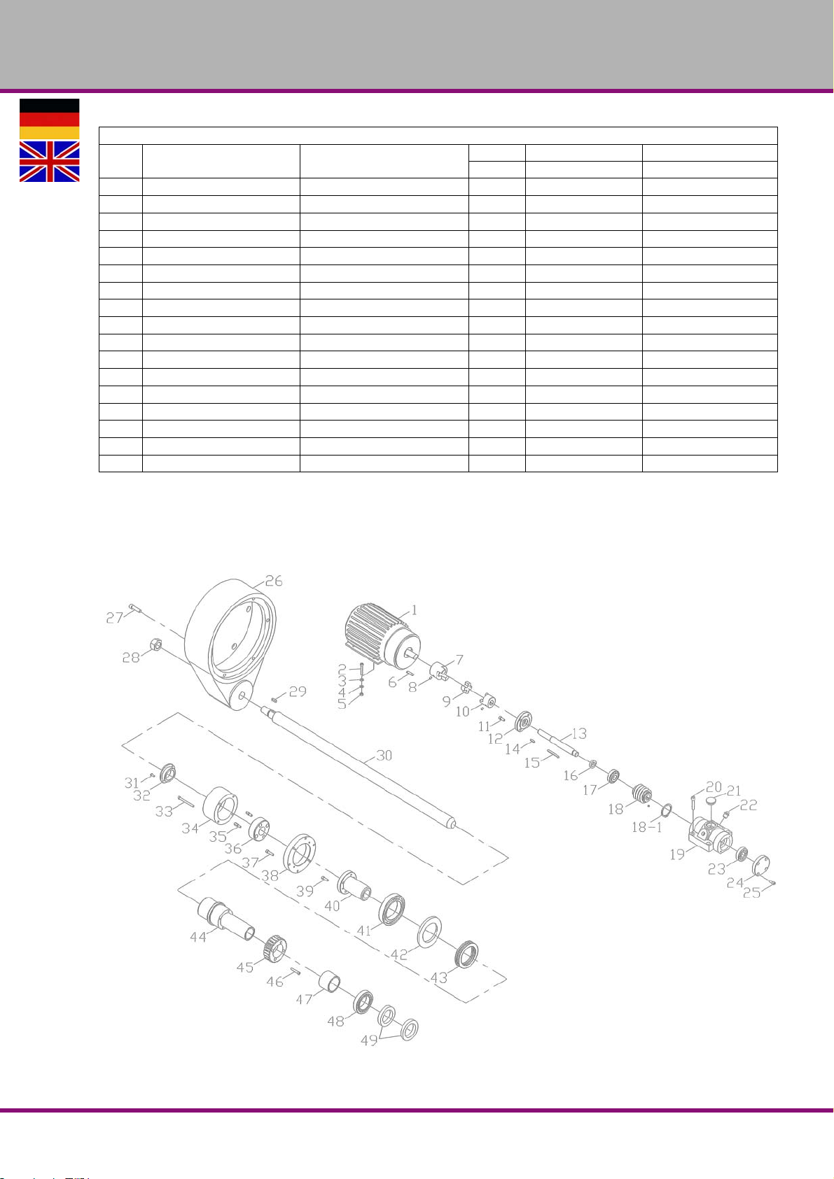
OPTIMUM
MASCHINEN - GERMANY
Ersatzteilliste - Spare part list - Säule - Column
Pos.
Bezeichnung Designation
52 Lager Bearing 1 51105 0405110552
53 Schraube Bolt 4 M8x30
54 fester Klemmblock Fixed Clamping Block 2 030490500354
55 Mutter Nut 1 030490500355
56 Lager Bearing 1 51105 04051105
57 Exzentrische Welle Eccentric Shaft 1 030490500357
58 Bolzen Bolt 1 M6x40
59 Klemmring Ring Clamp 1 030490500359
60 Bolzen Bolt 1 M10x25
61 Klemmhebel Locking lever 1 030490500361
62 Schraube Bolt 1 M8x16
63 Buchse Bushing 1 030490500363
64 Lager Bearing 1 51105 0401105
65 Mutter Nut 1 030490500365
66 Schraube Bolt 1 M6x55
67 Schraube Bolt 2 M8x40
68 Schaltkasten Electric Box 1 030490500368
Menge Grösse Artikelnummer
Qty. Size Item no.
6.5 Hubeinrichtung Ausleger - Lifting device cantilever
Ersatzteile - Spare parts
Version 1.0 2017-03-13 65Originalbetriebsanleitung
RD5 DE
Page 66

OPTIMUM
MASCHINEN - GERMANY
Ersatzteilliste - Spare part list - Hubeinrichtung Ausleger - Lifting device cantilever
Pos.
Bezeichnung Designation
1 Motor Motor 1 030490500401
2 Schraube Bolt 4 M6x40
3 Federring Spring Washer 4 M6
4 Scheibe Washer 4 M6
5 Sechskantmutter Nut 4 M6
6 Passfeder Key 1 6x30 030490500406
7 Kupplung Coupling 1 030490500407
8 Schraube Bolt 4 M6x8
9 Kupplungsteil Plastic joint 1 030490500409
10 Kupplung Coupling 1 030490500410
11 Schraube Bolt 4 M6x14
12 Lagerdeckel Bearing Cover Left 1 030490500412
13 Welle Worm Shaft 1 030490500413
14 Passfeder Key 1 5x20 030490500414
15 Passfeder Key 1 5x55 030490500415
16 Dichtung Oil Seal 1 17x28x7 030490500416
17 Kugellager Bearing 1 30303 04030303
18 Schnecke Worm shaft 1 030490500418
18-1 Sicherungsring Retainer 1 36 0304905004181
19 Gehäuse Worm hosing 1 030490500419
20 Schraube Bolt 4 M8x40
21 Oilschauglas Gage Fuel Level 1 030490500421
22 Verschluss Plug 2 P1/4" 030490500422
23 Kugellager Bearing 1 30303 04030303
24 Lagerdeckel Bearing Cover Right 1 030490500424
25 Schraube Bolt 4 M6x14
26 Gehäuse Nut Cover 1 030490500426
27 Schraube Bolt 6 030490500427
28 Sechskantmutter Nut 1 M24
29 Passfeder Key 1 6x20 030490500429
30 Spindel Leading screw 1 030490500430
31 Schraube Bolt 2 M5x12
32 Flansch Compressing Cover 1 030490500432
33 Schraube Bolt 4 M6x65
34 Abdeckung Safe Device Cover 1 030490500434
35 Schraube Bolt 2 030490500435
36 Klemmmutter Safety Nut 1 030490500436
37 Schraube Bolt 6 M6x25
38 Lagerdeckel Bearing Cover 1 030490500438
39 Schraube Bolt 4 M6x20
40 Hülse Brass sleeve 1 030490500440
41 Kugellager Bearing 1 6014Z 0406014Z
42 Ring Collar 1 030490500442
43 Kugellager Bearing 1 51114 04051114
44 Welle Up-down rolling Shaft 1 030490500444
45 Schneckenrad Worm Gear 1 030490500445
46 Schraube Bolt 4 M6x25
47 Buchse Collar 1 030490500446
43 Kugellager Bearing 1 32010 04032010
49 Dichtung Oil Seal 2 50x72x12 030490500449
Menge Grösse Artikelnummer
Qty. Size Item no.
RD5DE
Ersatzteile - Spare parts
Version 1.0 2017-03-13 66 Originalbetriebsanleitung
Page 67
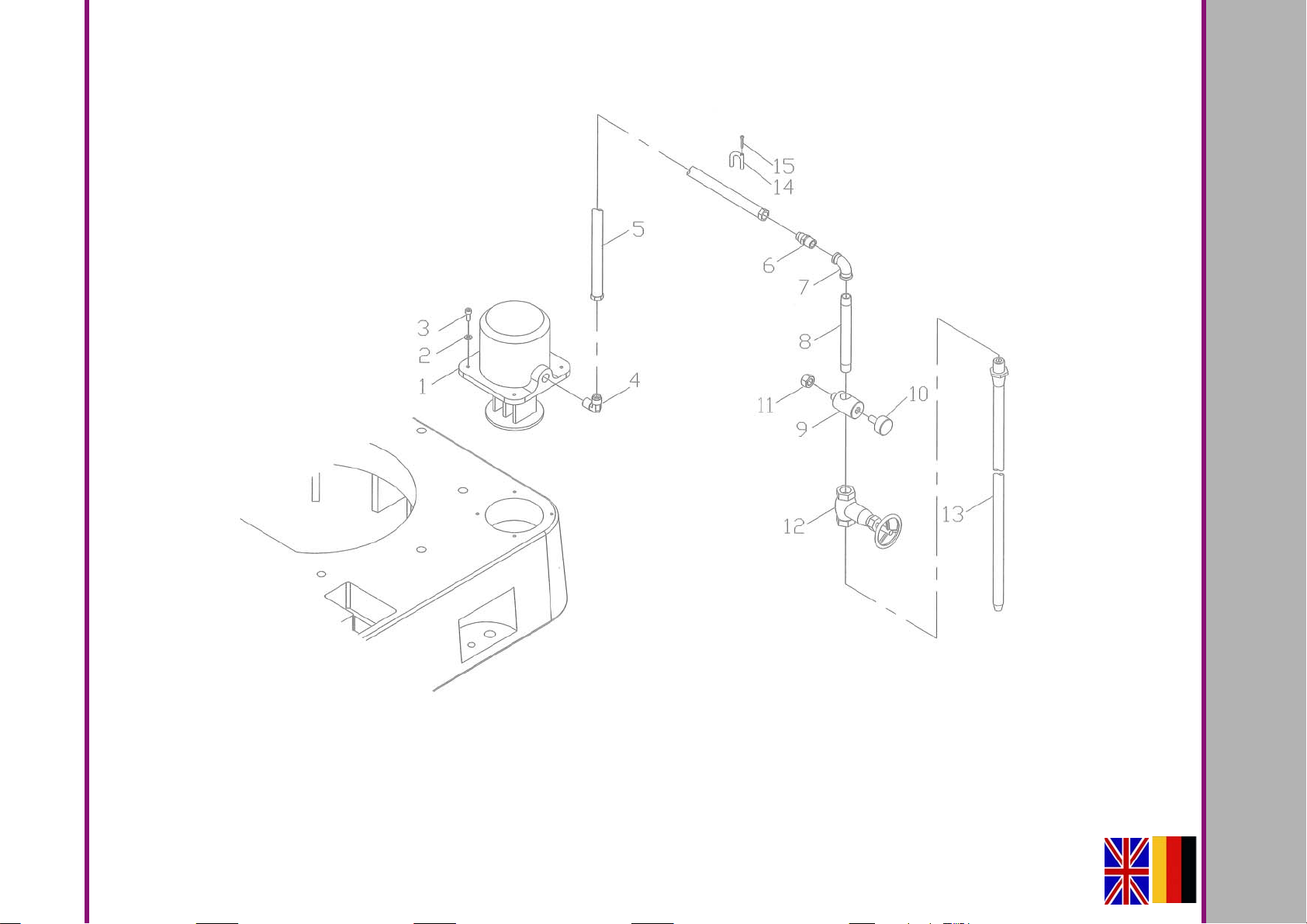
6.6 Kühlmitteleinrichtung - Coolant device
RD5DE
MASCHINEN - GERMANY
OPTIMUM
Version 1.0 2017-03-1367 Originalbetriebsanleitung
Ersatzteile - Spare parts
Page 68
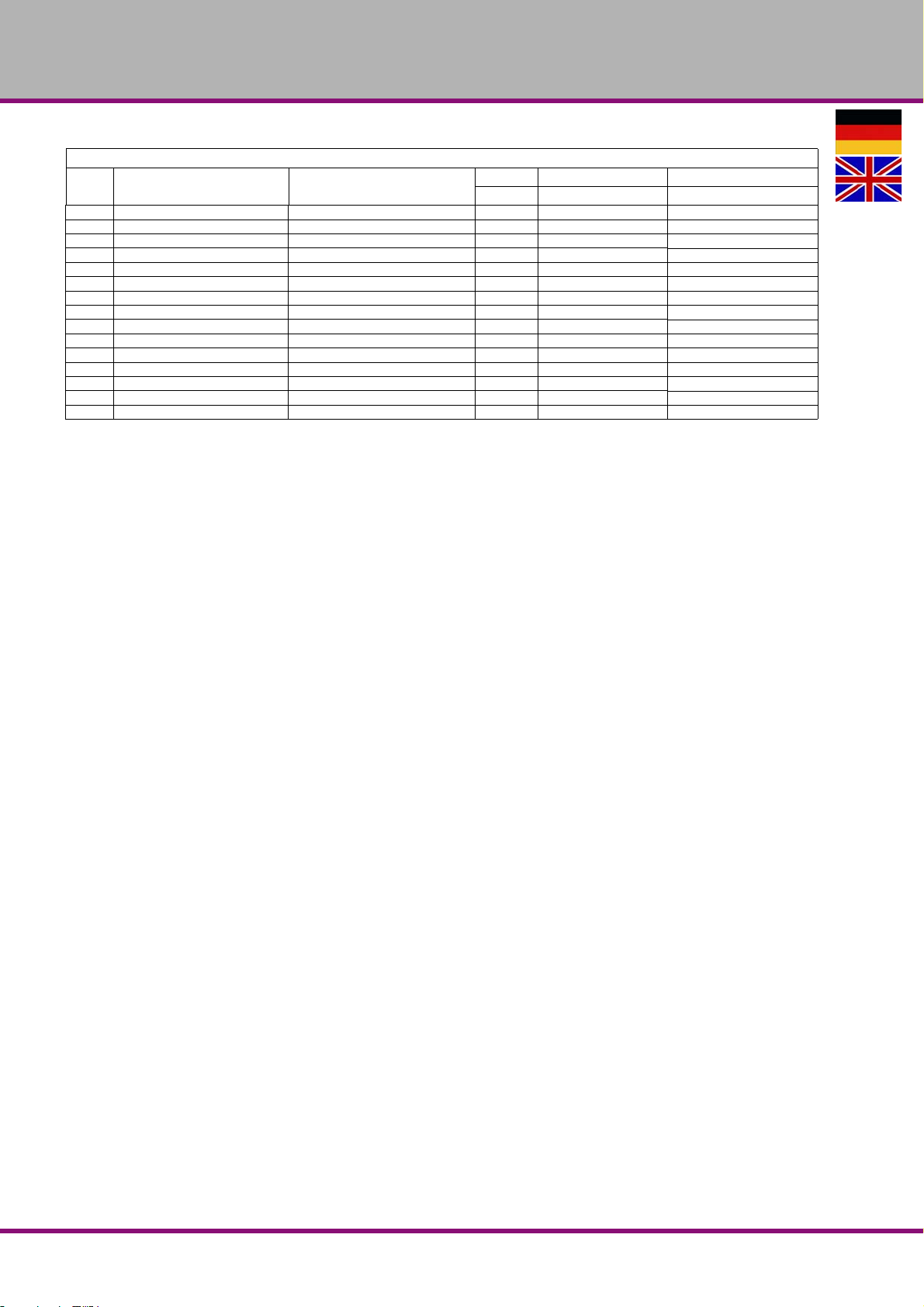
OPTIMUM
MASCHINEN - GERMANY
Ersatzteilliste - Spare part list - Kühlmitteleinrichtung - Coolant device
Pos.
Bezeichnung Designation
1 Kühlmittelpumpe Coolant pump 1 030490500501
2 Scheibe Washer 4 M6
3 Screw Schraube 4 M6x16
4 Kniestück Elbow 1 030490500504
5 Kunstoffleitung Net Plastic Pipe 1 030490500505
6 Anschluss Male Connector 1 030490500506
7 Kniestück Elbow 1 030490500507
8 Kunstoffleitung Tube 1 030490500508
9 Buchse Tube Sleeve 2 030490500509
10 Knopf Knob 2 030490500510
11 Sechskanmutter Nut 1 1/2" 030490500511
12 Wasserhahn Water Switch 1 3/8" 030490500512
13 Kühlmittelschlauch Spraying Pipe 1 3/8" 030490500513
14 Halter Tube Bundle 2 UC-5 030490500514
15 Schraube Schraube 2 M3x16
Menge Grösse Artikelnummer
Qty. Size Item no.
RD5DE
Ersatzteile - Spare parts
Version 1.0 2017-03-13 68 Originalbetriebsanleitung
Page 69
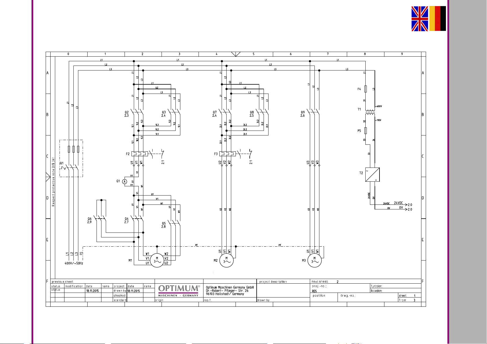
Ersatzteile - Spare parts
Kühlmittelpumpe
Coolant pump
Höhenverstellung Ausleger
Cantilever height adj ustment
Spindelantrieb
Spindle drive
Version 1.0 2017-03-13 69Originalbetriebsanleitung
6.7 Schaltplan - Wiring diagram
RD5 DE
MASCHINEN - GERMANY
OPTIMUM
Page 70
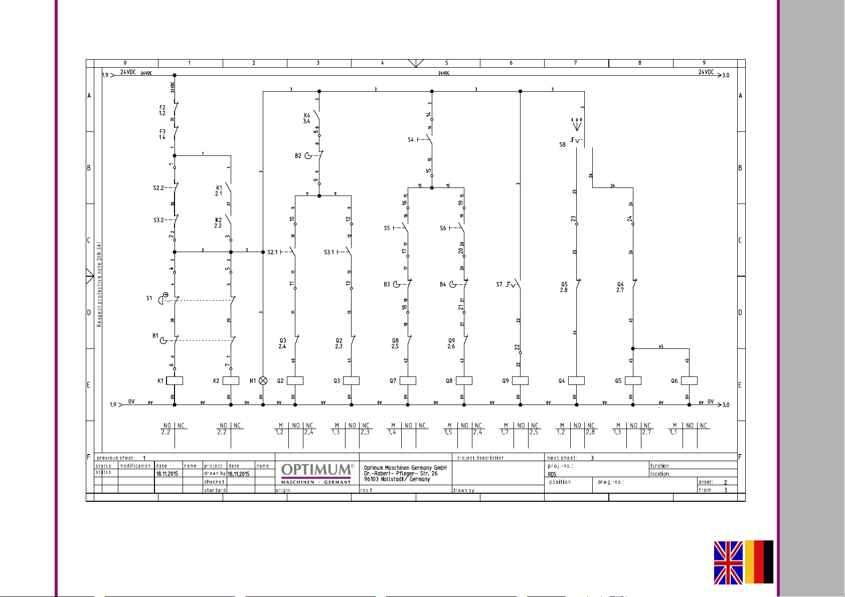
RD5DE
Not-Halt
Emergency stop
Drehrichtung Gegenuhrz.
Counter clockwise rotation
Drehrichtung
Gegenuhrzeigersi
Drehrichtung
Gegenuhrzeigersi
Ausleger ab
Cantilever down
Drehrichtung Uhrzeigersinn
Clockwise rotation
Drehrichtung
Gegenuhrzeigersi
Ausleger auf
Cantilever up
Drehzahl langsam
Speed low
Kühlmittel
Coolant
Drehzahl schnell
Speed high
MASCHINEN - GERMANY
OPTIMUM
Version 1.0 2017-03-1370 Originalbetriebsanleitung
Ersatzteile - Spare parts
Page 71
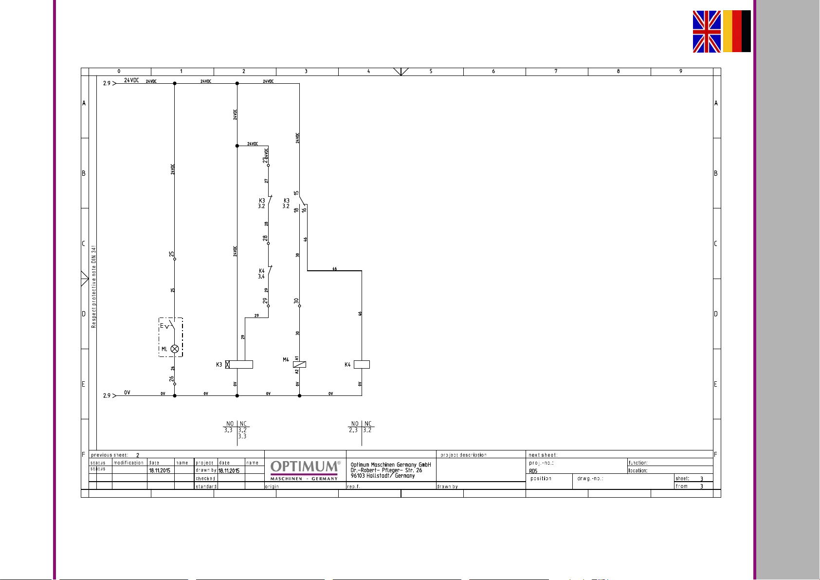
Ersatzteile - Spare parts
Maschinenlampe
Machine lamp
Zeitrelais Bremse
Brake time relays
Bremse
Brake
Version 1.0 2017-03-13 71Originalbetriebsanleitung
RD5 DE
MASCHINEN - GERMANY
OPTIMUM
Page 72
OPTIMUM
MASCHINEN - GERMANY
Ersatzteilliste - Spare part list - Elektrische Bauteile - Electric components
Pos.
Bezeichnung Designation
B1 Ausziehbare Schaltstange Extendible shift rod Allen Bradley Guard Master 03049050B1
B2 Endschalter Spindelstop Limit switch spindle stop Tend TM-1309 03049050B2
B3 Endschalter Oben Upper limit switch Tend-TM-1308 03049050B3
B4 Endschalter Unten Limit switch down Tend-TM-1308 03049050B4
F2 Motorschutzschalter Motor protection switch 3UA59/ 10-16A 03049050F2
F3 Motorschutzschalter Motor protection switch 3UA59/ 10-16A 03049050F3
F4 Sicherung Trafo primär Primary transformer fuse Tend TFBR 321 03049050F4
F5 Sicherung Trafo sekundär Secondary transformer fuse Tend TFBR 321 03049050F5
G1 Ampermeter Ampere meter S065 30A 03049050G1
H1 Betriebsleuchte Operating light ABB XB7-EVO-BP 03049050H1
K1 Not-Halt Relais Emergency stop relay Schneider RSB 1A120BD 03049050K1
K2 Not-Halt Relais Emergency stop relay Schneider RSB 1A120B 03049050K2
K3 Zeitrelais Time Relays Carlo Gavazzi DMB51 03049050K3
K4 Steuerrelais Bremse Brake control relay Schneider RSB 1A120BD 03049050K4
M1 Antriebsmotor zweistufig Two stage drive motor YD132M-8/4, 3-4,5kW 03049050M1
M2 Motor Kühlmittelpumpe Elevating motor cantilever AB25, 40W 03049050M2
M3 Motor Kühlmittelpumpe Motor coolant pump 0,1 KW 03049050M3
M4 Elektomagnet Spindelbremse Electromagnetic spindle brake 03049050M4
ML Maschinenleuchte Machine light ONN-IMS-24v 03049050ML
Q1 Hauptschalter Main switch FS 203003B 03049050Q1
Q2 Schütz Spindel Rechtslauf Contactor spindle clockwise Siemens 3RT2017-1BB42 03049050Q2
Q3 Schütz Spindel Linkslauf Contactor spindle counter clockwise Siemens 3RT2017-1BB42 03049050Q3
Q4 Schütz Spindel langsam Contactor spindle low speed Siemens 3RT2017-1BB42 03049050Q4
Q5 Schütz Spindel schnell Contactor spindle high speed Siemens 3RT2017-1BB42 03049050Q5
Q6 Schütz Spindel schnell Contactor spindle high speed Siemens 3RT2017-1BB42 03049050Q6
Q7 Schütz Hochfahren Contactor elevating up Siemens 3RT2017-1BB42 03049050Q7
Q8 Schütz Runterfahren Contactor elevating down Siemens 3RT2017-1BB42 03049050Q8
Q9 Schütz Kühlmittelpumpe Contactor coolant pump Siemens 3RT2017-1BB42 03049050Q9
S1 Not-Halt-Schalter Emergency stop button ABB-MCB01 03049050S1
S2.2 Positionsschalter Rechtslauf Position switch clockwise Omron V-15-1ES 03049050S22
S3.2 Positionsschalter Linkslauf Position switch counter clockwise Omron V-15-1ES 03049050S32
S4 Endschalter Klemmung Limit switch clamping Tend TZ7311 03049050S4
S5 Taster Hochfahren Button up ABB-CP1-10B-11 03049050S5
S6 Taster Runterfahren Button down ABB-CP1-10B-11 03049050S6
S7 Drehschalter Kühlmittelpumpe Rotary switch coolant pump ABB C2552-10B-10 03049050S7
S8 Geschwindigkeitswahlschalter Speed selector switch Kedu ZH-1 03049050S8
T1 Transformator Transformer Shin Hsing SHST-150C 03049050T1
T2 Netzteil Power supply RS-50-24 03049050T2
Hersteller Artikelnummer
Manufacturer Item no.
RD5DE
Ersatzteile - Spare parts
Version 1.0 2017-03-13 72 Originalbetriebsanleitung
Page 73
1.0 2017-03-13 73
Schmierstoffe
Lubricant
Lubrifiant
Viskosität
Viskosity
Viscosité ISO VG
DIN 51519 mm²/s
(cSt)
Kennzeich-
nung nach
DIN 51502
Getriebeöl
Gear oil
Huile de réducteur
Hydrauliköl
Hydraulic oil
Huile hydraulique
Getriebefett
Gear grease
Graisse de
réducteur
VG 680 CLP 680
VG 460 CLP 460
VG 320 CLP 320
VG 220 CLP 220
VG 150 CLP 150
VG 100 CLP 100
VG 68 CLP 68
VG 46 CLP 46
VG 32 CLP 32
VG 32 CLP 32
VG 46 CLP 46
G 00 H-20
Aral Degol BG
680
Aral Degol BG
460
Aral Degol BG
320
Aral Degol BG
220
Aral Degol BG
150
Aral Degol BG
100
Aral Degol BG
68
Aral Degol BG
46
Aral Degol BG
32
Aral Vitam GF 32BP Energol
Aral Vitam GF 46BP Energol
Aral FDP 00
(Na-verseift)
Aralub MFL 00
(Li-verseift)
BP Energol
GR-XP 680
BP Energol
GR-XP 460
BP Energol
GR-XP 320
BP Energol
GR-XP 220
BP Energol
GR-XP 150
BP Energol
GR-XP 100
BP Energol
GR-XP 68
BP Bartran
46
BP Bartran
32
HLP HM 32
HLP HM 46
BP
Energrease
PR-EP 00
SPARTAN
EP 680
SPARTAN
EP 460
SPARTAN
EP 320
SPARTAN
EP 220
SPARTAN
EP 150
SPARTAN
EP 100
SPARTAN
EP 68
NUTO H 46
(HLP 46)
NUTO H 32
(HLP 32)
NUTO H 32
(HLP 32)
NUTO H 46
(HLP 46)
FIBRAX EP
370
(Na-verseift)
Klüberoil
GEM 1-680
Klüberoil
GEM 1-460
Klüberoil
GEM 1-320
Klüberoil
GEM 1-220
Klüberoil
GEM 1-150
Klüberoil
GEM 1-100
Klüberoil
GEM 1-68
Klüberoil
GEM 1-46
Klübersynth
GEM 4- 32 N
LAMORA
HLP 32
LAMORA
HLP 46
MICRO-
LUBE GB 00
Mobilgear
636
Mobilgear
634
Mobilgear
632
Mobilgear
630
Mobilgear
629
Mobilgear
627
Mobilgear
626
Mobil DTE
25
Mobil DTE
24
Mobil Nuto
HLP 32
Mobil Nuto
HLP 46
Mobilux
EP 004
Shell Omala
680
Shell Omala
460
Shell Omala
320
Shell Omala
220
Shell Omala
150
Shell Omala
100
Shell Omala
68
Shell Tellus
S 46
Shell Tellus
S 32
Shell Tellus
S2 M 32
Shell Tellus
S2 M 46
Shell Alvania
GL 00
(Li-verseift)
Meropa 680
Meropa 460
Meropa 320
Meropa 220
Meropa 150
Meropa 100
Meropa 68
Anubia EP
46
Anubia EP
32
Rando HD
HLP 32
Rando HD
HLP 46
Marfak 00
MASCHINEN - GERMANY
OPTIMUM
Page 74

Spezialfette,
wasserabweisend
Special greases,
water resistant
Graisses spéciales,
déperlant
Aral Aralub
Energrease
PR 9143
ALTEMP
Q NB 50
Klüberpaste
ME 31-52
Mobilux EP 0
Mobil Grea-
serex 47
MASCHINEN - GERMANY
OPTIMUM
1.0 2017-03-1374
Wälzlagerfett
Bearing grease
Graisse de
roulement
Öle für Gleitbahnen
Oils for slideways
Huiles pour glis-
sières
Öle für Hochfre-
quenzspindeln
Oils for Built-in
spindles
Huiles pour broches
à haute vitesse
Fett für Hochfre-
quenzspindeln
Grease for Built-in
spindles
Graisse pour bro-
ches à haute vitesse
Kühlschmiermittel
Cooling lubricants
Lubrifiants de refro-
idissement
K 3 K-20
(Li-verseift)
VG 68 CGLP 68
VG 68 Deol BG 68
Schneidöl Aquacut B,
5 L Gebinde, Artikel Nr. 3601751
EG Sicherheitsdatenblatt
http://www.optimum-daten.de/data-
sheets/EG-Datenblatt_Aquacut-
B.pdf
BP
Aralub HL 3
Aral Deganit
BWX 68
METAFLUX-Fett-Paste (Grease paste) Nr. 70-8508
Aral Emusol BP Sevora Esso Kutwell Mobilcut Shell Adrana
Energrease
LS 3
BP
Maccurat
D68
Emergol
HLP-D68
METAFLUX-Moly-Spray Nr. 70-82
BEACON 3
ESSO Febis
K68
Spartan EP
68
CENTO-
PLEX 3
LAMORA
D 68
Mobilux 3
Mobil Vactra
Oil No.2
Drucköl KLP
68-C
Shell Alvania
R 3 Alvania
G 3
Shell Tonna
S2 M 68
Shell Omala
68
Multifak
Premium 3
Way
lubricant X
68
Chevron
Soluble Oil B
Page 75

7 Malfunctions
OPTIMUM
MASCHINEN - GERMANY
Malfunction
Spindle does not turn • Motor protection switch has
It is not possible to lift the cantilever.
The spindle and the drilling
head leak oil.
Bit "burnt“ • Drill speed too high /feed too high
Cause/
possible effects
released or is defective.
• Supply voltage too low or a phase is
missing.
• The switch on the clamping lever
does not release.
• Position switch on the spindle
sleeve does not release.
• Motor defective.
• End position switch switches off
• Motor defective.
• Too much oil in the gear box above • Check oil level and reduce it if
• Chips do not come out of the drill
hole.
• Drill blunt
• No or too little cooling
Solution
• Check motor protective switch or
switch it on again if applicable.
• Check supply tension
• Check position switch clamping
lever.
• Check position switch of the spindle sleeve.
• Check motor and replace it if
required.
• Check end position switch
• Check motor and replace it if
required.
required
• Select another speed
• Extract drill more often during work
• Sharpen or
use new drill
• Use cooling agent
Drill tip is running off centre,
the drilled hole is non-round
Drill is defective • No base / support used. • Use support and clamp it with the
Drill is running non-round or
shaking
It is not possible to insert the
drill chuck or the taper mandrel
Precision of the work deficient • Irregularly heavy or tensed work-
• Hard points on the workpiece
• Length of the cutting spirals/or
angles on the tool are unequal
• Drill deformed
• Bit deformed
• Worn out spindle bearings
• Drill is not correctly clamped.
• Drill chuck defective
• Dirt, grease or oil on the taper
inside of the drill chuck or on the
taper surface of the drill spindle
• Positioning the follower in the drill
spindle is not considered
piece
• Inexact horizontal position of the
work-piece holder
• Use new drill
workpiece
• Use new drill
• Have the spindle bearings replaced
• Correctly clamp drill
• Replace the drill chuck
• Clean surfaces well
• Keep surfaces free of grease
• Balance the piece statically and
secure without straining
• Adjust workpiece-holder
Malfunctions
Version 1.0 2017-03-13 Page 75Original operating instructions
RD5 GB
Page 76
OPTIMUM
MASCHINEN - GERMANY
8 Appendix
8.1 Copyright
This document is protected by copyright. All derived rights are reserved, especially those of
translation, re-printing, use of figures, broadcast, reproduction by photo-mechanical or similar
means, and recording in data processing systems, either partial or total.
Subject to technical changes without notice.
8.2 Terminology/Glossary
Term Explanation
Drill drift Tool to release the bit or the drill chuck from the drill spindle
Drill chuck Drill bit adapter
Drill head Upper part of the radial drilling machine
Drill sleeve fixed hollow shaft which runs in the drill spindle.
Drilling spindle Shaft activated by the motor
Drilling table Supporting surface, clamping surface
Taper mandrel Cone of the drill or of the drill chuck
Quill lever Manual operation for the drill feed
Quick-action drill chuck drill holding fixture to be clamped manually.
Workpiece part to be drilled, part to be machined.
Tool Milling cutter, drill bit, countersink, etc.
8.3 Storage
ATTENTION!
Incorrect and improper storage might result in damage or destruction of electrical and
mechanical machine components.
Store packed and unpacked parts only under the intende d environmental conditions.
Follow the instructions and information on the transport box.
Fragile goods
(Goods require careful handling)
Protect against moisture and humid environment
"Environmental conditions of rel. humidity“ on page
21
RD5GB
Appendix
Version 1.0 2017-03-13Page 76 Original operating instructions
Page 77

OPTIMUM
MASCHINEN - GERMANY
Prescribed position of the packing case
(Marking the top surface - arrows pointing up)
Maximum stacking height
Example: not stackable - do not stack a second
packing case on top of the first one.
darf keine weitere gestapelt werden.
Consult Optimum Maschinen Germany GmbH if the machine and accessories are stored for
more than three months or are stored under different environmental conditions than those specified here.
"Environmental conditions storage and transport“ on page 21.
Appendix
Version 1.0 2017-03-13 Page 77Original operating instructions
RD5 GB
Page 78

OPTIMUM
MASCHINEN - GERMANY
8.4 Liability claims/warranty
Besides the legal liability claims for defects of the customer towards the seller, the manufacturer of the product, OPTIMUM GmbH, Robert-Pfleger-Straße 26, D-96103 Hallstadt, does not
grant any further warranties unless they are listed below or were promised as part of a single
contractual provision.
Liability or warranty claims are processed at OPTIMUM GmbH's discretion either
directly or through one of its dealers.
Any defective products or components of such products will either be repaired or
replaced by components that are free from defects. Ownership of replaced products or
components is transferred to OPTIMUM Maschinen Germany GmbH.
The automatically generated original proof of purchase which shows the date of purchase,
the type of machine and the serial number, if applicable, is the precondition in order to
assert liability or warranty claims. If the original proof of purchase is not presented, we are
not able to perform any services.
Defects resulting from the following circumstances are excluded from liability and warranty
claims:
- Using the product beyond the technical options and proper use, in particular due to overstraining of the machine.
- Any defects arising by one's own fault due to faulty operations or if the operating manual
is disregarded.
- Inattentive or incorrect handling and use of improper equipment.
- Unauthorised modifications and repairs.
- Insufficient installation and safeguarding of the machine.
- Disregarding the installation requirements and conditions of use
- atmospheric discharges, overvoltage and lightning strokes as well as chemical influences.
The following items are also not subject to liability or warranty claims:
- Wearing parts and components which are subject to a standard wear as intended such
as e.g. V-belts, ball bearings, illuminants, filters, sealings, etc.
- Non reproducible software errors
Any services, which OPTIMUM GmbH or one of its agents performs in order to fulfil any
additional warranty are neither an acceptance of the defects nor an acceptance of its obligation to compensate. These services neither delay nor interrupt the warranty period.
The court of jurisdiction for legal disputes between businessmen is Bamberg.
If any of the aforementioned agreements is totally or partially inoperative and/or invalid, a
provision that most closely approaches the intent of the guarantor and remains within the
framework of the limits of liability and warranty which are specified by this contract is
deemed agreed.
8.5 Advice for disposal / Options of reuse:
Please dispose of your equipment in an environmentally friendly and professional manner by
not placing waste in the environment.
Please do not simply throw away the packaging and later the disused machine, but dispose of
both in accordance with the guidelines laid down by your city council/local authority or by an
authorised disposal company.
RD5GB
Version 1.0 2017-03-13Page 78 Original operating instructions
Appendix
Page 79

OPTIMUM
MASCHINEN - GERMANY
8.5.1 Decommissioning
CAUTION!
Used devices need to be decommissioned in a professional way in order to avoid later
misuses and endangerment of the environment or persons.
Unplug the power cord.
Cut the connection cable.
Remove all operating materials from the used device which are harmful to the envi-
ronment.
If applicable remove batteries and accumulators.
Disassemble the machine if required into easy-to-handle and reusable assemblies
and component parts.
Dispose of machine components and operating fluids using the intended disposal
methods.
8.5.2 Disposal of new device packaging
All used packaging materials and packaging aids from the machine are recyclable and generally need to be supplied to the material reuse.
Cardboard packaging can be supplied to the disposal or the reuse.
Any packaging components made of cardboard box can be chopped up and supplied to the
waste paper collection.
The films are made of polyethylene (PE) and the cushion parts are made of polystyrene (PS).
These materials can be reused after reconditioning if they are passed to a collection station or
to the appropriate waste management enterprise.
Only pass on the packaging materials correctly sorted, to allow direct reuse.
8.5.3 Disposal of the old device
INFORMATION
Please take care in your interest and in the interest of the environment that all component parts
of the machine are only disposed of in the intended and admitted way.
Please note that the electrical devices comprise a variety of reusable materials as well as environmentally hazardous components. Please ensure that these components are disposed of
separately and professionally. In case of doubt, please contact your municipal waste management. If appropriate, call on the help of a specialist waste disposal company for the treatment of
the material.
8.5.4 Disposal of electrical and electronic components
Please make sure that the electrical components are disposed of professionally and according
to the statutory provisions.
The device is composed of electrical and electronic components and must not be disposed of
as household waste. According to the European Directive 2002/96/EC regarding electrical and
electronic used devices and the implementation of national legislation, used power tools and
electrical machines need to be collected separately and supplied to an environmentally friendly
recycling centre.
As the machine operator, you should obtain information regarding the authorised collection or
disposal system which applies for your company.
Please make sure that the electrical components are disposed of professionally and according
to the legal regulations. Please only throw depleted batteries in the collection boxes in shops or
at municipal waste management companies.
Appendix
Version 1.0 2017-03-13 Page 79Original operating instructions
RD5 GB
Page 80

OPTIMUM
MASCHINEN - GERMANY
8.5.5 Disposal of lubricants and coolants
ATTENTION!
Please imperatively make sure to dispose of the used coolant and lubricants in an
environmentally compatible manner. Observe the disposal instructions of your
municipal waste management companies.
INFORMATION
Used coolant emulsions and oils should not be mixed since it is only possible to reuse oils without pre-treatment when they have not been mixed.
The disposal instructions for used lubricants are made available by the manufacturer of the
lubricants. If necessary, request the product-specific data sheets.
8.6 Disposal via municipal collection facilities
Disposal of used electrical and electronic components
(Applicable in the countries of the European Union and other European countries with a separate collecting system for those devices).
The sign on the product or on its packing indicates that the product must not be handled as
common household waste, but that is needs to be disposed of at a central collection point for
recycling. Your contribution to the correct disposal of this product will protect the environment
and the public health. Incorrect disposal constitutes a risk to the environment and public health.
Recycling of material will help reduce the consumption of raw materials. For further information
about the recycling of this product, please consult your District Office, municipal waste collection station, or the shop where you purchased the product.
8.7 RoHS, 2002/95/EC
The symbol on the product or on its packing indicates that this product complies with the European directive 2002/95/EC.
8.8 Product follow-up
We are required to perform a follow-up service for our products which extends beyond shipment.
We would be grateful if you could send us the following information:
Modified settings
Experiences with the radial drilling machine, which could be important for other users
Recurring malfunctions
Optimum Maschinen Germany GmbH
Dr.-Robert-Pfleger-Str. 26
D-96103 Hallstadt
Fax +49 (0) 951 - 96 555 - 888
Email: [email protected]
RD5GB
Version 1.0 2017-03-13Page 80 Original operating instructions
Appendix
Page 81

8.9 EC - declaration of conformity
Hallstadt, 10/12/2015
Kilian Stürmer
(CEO, General manager)
in accordance with the Machinery Directive 2006/42/EC Annex II 1.A
OPTIMUM
MASCHINEN - GERMANY
The manufacturer/
distributor:
hereby declares that the following product
Product designation: Radial drilling machine
Type designation:
Serial number: _ __ __ __ __
Year of manufacture: 20__
Manual radial drilling machine for craft and industrial plants which meets all the relevant provisions of the
above mentioned Directive 2006/42/EC as well as the other directives applied (below) including their
amendments in force at the time of declaration.
The following other EU Directives have been applied:
EMC Directive 2014/30/EC
Low Voltage Directive 2014/35/EC
The safety objective meet the requirement of EC Directive 2006/42/EC.
The following harmonized standards were applied:
EN 1837:1999+A1:2009 - Safety of machinery - Integral lighting of machines
EN 12717:2001+A1:2009 - Safety of machine tools - Drilling machines
EN 60204-1:2006/A1:2009 -Safety of machinery - Electrical equipment of machines - Part 1: General
requirements
EN 1005-2:2003+A1:2008 - Safety of machinery - Human physical performance - Part 2: Manual handling
of machinery and component parts of machinery
EN ISO 13849 - Safety of machinery - Safety-related parts of control systems
EN ISO 12100:2010 - Safety of machinery - General principles for design - Risk assessment and risk
reduction
Optimum Maschinen Germany GmbH
Dr.-Robert-Pfleger-Str. 26
D - 96103 Hallstadt
RD5
Person responsible for the document: Kilian Stürmer
Phone: +49 (0) 951 96555 - 800
Address: Dr.-Robert-Pfleger-Str. 26
D - 96103 Hallstadt
Page 82

OPTIMUM
MASCHINEN - GERMANY
Index
A
Accessories .......................................................... 24
Accident report
Ammeter
Assembly
..................................................... 19
............................................................... 40
........................................................ 24, 28
C
Classification of hazards ........................................ 7
Control and indicating elements
Copyright
Customer service
Customer service technician
.............................................................. 76
................................................. 51
........................... 35
................................ 51
D
Disinfection
Cooling lubricant tank
Disposal
Drill depth
Drilling head
............................................................... 80
automatic
move
........................................................ 41
............................................................... 38
..................................... 52
E
Electronics ............................................................ 19
Emergency stop
reset
................................................................ 40
F
Fixing .................................................................... 30
I
Inspection ............................................................. 44
Installation
Intended use
............................................................ 28
.......................................................... 9
L
Load suspension point ......................................... 25
M
Machine
switch off
switch on
Maintenance
Malfunctions
Misuse
......................................................... 40
......................................................... 39
................................................... 43, 44
......................................................... 75
.................................................................... 9
O
Obligations
of the operating company
of the operator
Operation
............................................................. 35
................................................. 12
............................... 12
P
Personal protective equipment ............................. 17
Power failure
Power supply
Product follow-up
........................................................ 40
........................................................ 34
................................................. 80
R
Restoring
readiness for operation
................................... 40
S
Safety
during maintenance
during operation
Safety devices
Safety instructions
Shift rod
adjust
Specialist dealer
Speed
adjustment
......................................................13
...............................................................38
.......................................................39
.........................................18
...............................................18
..................................................7
...................................................51
T
Technical data ......................................................20
Transport
Transportation lock
Type plate
..............................................................24
...............................................33
...............................................................6
W
Warming up the machine ......................................34
Warning notes
.........................................................7
RD5GB
Version 1.0 2017-03-13Page 82 Original operating instructions
 Loading...