

Optimum OPTIDRILL B 23PRO, OPTIDRILL B 33PRO VARIO, OPTIDRILL B 23PRO VARIO, OPTIDRILL B 26PRO VARIO, OPTIDRILL B 26PRO Operating Manual
...Page 1
OPTIMUM
MASCHINEN - GERMANY
Operating manual
Version 2.0.2
Bench drilling machine
Upright drilling machine
GB
Page 2

OPTIMUM
MASCHINEN - GERMANY
Table of contents
1 Safety
1.1 Safety instructions (warning notes)...........................................................................................................8
1.1.1 Classification of hazards............................. ..............................................................................................8
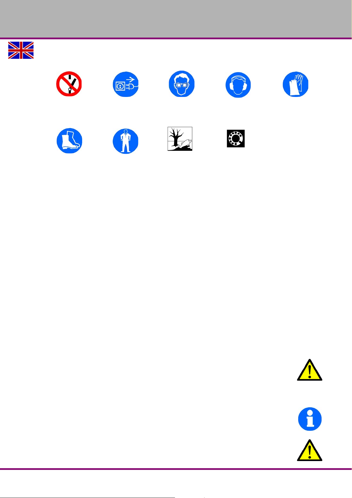
1.1.2 Other pictograms......................................................................................................................................9
1.2 Intended use.............................................................................................................................................9
1.3 Reasonably foreseeable misuse.............................................................................................................10
1.3.1 Avoiding misuses....................................................................................................................................10
1.4 Possible dangers caused by the drilling machine...................................................................................11
1.5 Qualification of the staff..........................................................................................................................11
1.5.1 Target group...........................................................................................................................................11
1.5.2 Authorized staff.......................................................................................................................................12
1.6 Operator positions ..................................................................................................................................13
1.7 Safety measures during operation..........................................................................................................13
1.8 Safety devices ........................................................................................................................................13
1.9 EMERGENCY-STOP push button............................... .. ... ......................................................................14
1.10 Separating protective devices.................................................................................................................14
1.10.1 Covering cap of the pulley..................................... ... ... ...........................................................................14
1.10.2 Drill chuck protection ..............................................................................................................................14
1.11 Drilling table............................................................................................................................................15
1.12 Prohibition, warning and mandatory signs..............................................................................................15
1.13 Safety check...........................................................................................................................................15
1.14 Individual protection gear........................................................................................................................16
1.15 Safety during operation...........................................................................................................................17
1.16 Safety during maintenance.....................................................................................................................17
1.16.1 Disconnecting and securing the drilling machine ....................................................................................17
1.16.2 Using lifting equipment ...........................................................................................................................17
1.16.3 Mechanical maintenance work ...............................................................................................................18
1.17 Accident report......................................... ... ... .......................................................... ...............................18
1.18 Electrical system.....................................................................................................................................18
2 Technical data
2.1 Electrical connection...............................................................................................................................19
2.2 Power drive motor...................................................................................................................................19
2.3 Drilling capacity in steel S235JR ............................................................................................................19
2.4 Continuous drilling capacity in steel S235JR..........................................................................................19
2.5 Spindle seat............................................................................................................................................19
2.6 T-slots - size .......................................................... ... ..............................................................................19
2.7 Table size ...............................................................................................................................................19
2.8 Spindle stroke.........................................................................................................................................19
2.9 Throat depth ...........................................................................................................................................19
2.10 Machine height .......................................................................................................................................19
2.11 Column diameter ....................................................................................................................................19
2.12 Distance spindle - table ..........................................................................................................................19
2.13 Distance spindle - stand .........................................................................................................................19
2.14 Dimension ...............................................................................................................................................19
2.18 Emissions ...............................................................................................................................................20
2.15 Weight of machine [kg]....................................... ... .................................................................................20
2.16 Spindle speeds.......................................................................................................................................20
2.17 Environmental conditions temperature...................................................................................................20
3 Assembly
3.1 Scope of delivery....................................................................................................................................22
3.2 Transport ................................................................................................................................................22
B17Pro | B23Pro | B26Pro | B33ProGB
Version 2.0.2 2014-11-04Page 2 Original operating instructions
Page 3

OPTIMUM
MASCHINEN - GERMANY
3.3 Storage...................................................................................................................................................23
3.4 Installation and assembly.......................................................................................................................23
3.4.1 Requirements to the install a tion site ......................................................................................................23
3.4.2 Assembly ................................................................................................................................................24
3.5 Installation..............................................................................................................................................27
3.5.1 Fixing......................................................................................................................................................27
3.6 First commissioning................................................................................................................................29
3.6.1 Warming up the machine .......................................................................................................................30
3.7 Drilling machines with frequency converter............................................................................................30
4Operation
4.1 Control and indicating elements.............................................................................................................31
4.2 Safety.....................................................................................................................................................32
4.2.1 Drill depth stop ................................................... ....................................................................................32
4.2.2 Inclination table ......................................................................................................................................32
4.3 Speed change........................................................................................................................................33
4.3.1 Speed tables ..........................................................................................................................................33
4.4 Standard values for speeds with HSS – Eco – twist drilling...................................................................37
4.5 Switching on the machine ......................................................................................................................37
4.6 Switching off the machine ......................................................................................................................37
4.7 Quick-action drill chuck ..........................................................................................................................37
4.7.1 Disassembly quick- action drill chuck .....................................................................................................38
4.7.2 Assembly quick- action drill chuck..........................................................................................................38
4.8 Cooling...................................................................................................................................................38
4.9 Before starting work ...............................................................................................................................39
4.10 During work............................................................................................................................................39
5 Determining the cutting speed and the speed
5.1 Table cutting speeds / infeed .................................................................................................................40
5.2 Speed table............................................................................................................................................40
5.3 Examples to calculatory determine the required speed for your drilling machine ..................................42
6 Maintenance
6.1 Safety.....................................................................................................................................................43
6.1.1 Preparation.............................................................................................................................................43
6.1.2 Restarting...............................................................................................................................................43
6.2 Inspection and maintenance ..................................................................................................................44
6.3 Repair.....................................................................................................................................................46
6.3.1 Customer service technician..................................................................................................................46
7 Ersatzteile - Spare parts - B17Pro, B23Pro, B26Pro, B33Pro - (Vario)
7.1 OPTI B17Pro..........................................................................................................................................47
7.1.1 Bohrfutterschutz alter Typ - Drill chuck protection old type - B17Pro.....................................................48
7.1.2 Ersatzteilliste B17Pro .............................................................................................................................48
7.1.3 Bohrfutterschutz neuer Typ - Drill chuck protection new type - B17Pro.................................................51
7.2 B23Pro, B23Pro Vario............................................................................................................................52
7.2.1 Ersatzteilliste B23Pro, B23Pro Vario......................................................................................................53
7.2.2 Bohrfutterschutz alter Typ - Drill chuck protection old type - B23Pro.....................................................56
7.2.3 Bohrfutterschutz neuer Typ - Drill chuck protection new type - B23Pro.................................................57
7.3 OPTI B26Pro, B26Pro Vario...................................................................................................................58
7.3.1 Ersatzteilliste B26Pro, B26Pro Vario......................................................................................................59
7.3.2 Bohrfutterschutz alter Typ - Drill chuck protection old type - B26Pro.....................................................62
7.3.3 Bohrfutterschutz neuer Typ - Drill chuck protection new type - B26Pro.................................................63
7.4 B33Pro, B33Pro Vario............................................................................................................................64
7.4.1 Ersatzteilliste B33Pro, B33Pro Vario......................................................................................................65
7.4.2 Bohrfutterschutz alter Typ - Drill chuck protection old type - B33Pro.....................................................68
7.4.3 Bohrfutterschutz neuer Typ - Drill chuck protection new type - B33Pro.................................................69
7.5 Schaltplan - Wiring diagram - B17Pro, B23Pro - 230V ..........................................................................70
Version 2.0.2 2014-11-04 Page 3Original operating instructions
B17Pro | B23Pro | B26Pro | B33Pro GB
Page 4

OPTIMUM
MASCHINEN - GERMANY
7.6 Schaltplan - Wiring diagram - B23Pro, B26Pro, B33Pro - 400 V............................................................71
7.7 Schaltplan - Wiring diagram - B23Pro Vario, B26Pro Vario, B33Pro Vario ............................................72
8 Malfunctions
8.1 Malfunctions on the drilling machine.......................................................................................................73
9 Annex
9.1 Copyright ................................................................................................................................................74
9.2 Terminology/Glossary.............................................................................................................................74
9.3 Change information manual....................................................................................................................74
9.4 Liability claims for defects / warranty......................................................................................................75
9.5 Advice for disposal / Options of re-use...................................................................................................75
9.5.1 Decommissioning ...................................................................................................................................76
9.5.2 Disposal of the packaging of the new machine ......................................................................................76
9.5.3 Disposal of the used machine.................................................................................................................76
9.5.4 Disposal of electrical and electronic components...................................................................................76
9.5.5 Disposal of lubricants and cooling lubricants..........................................................................................77
9.6 Disposal via municipal collecting points..................................................................................................77
9.7 RoHS , 2002/95/CE................................................................................................................................77
9.8 Product follow-up....................................................................................................................................77
9.9 EC - Declaration of Conformity B17Pro..................................................................................................78
9.10 EC - Declaration of Conformity B23Pro..................................................................................................79
9.11 EC - Declaration of Conformity B23Pro Vario.........................................................................................80
9.12 EC - Declaration of Conformity B26Pro..................................................................................................81
9.13 EC - Declaration of Conformity B26Pro Vario.........................................................................................82
9.14 EC - Declaration of Conformity B33Pro..................................................................................................83
9.15 EC - Declaration of Conformity B33Pro Vario.........................................................................................84
B17Pro | B23Pro | B26Pro | B33ProGB
Version 2.0.2 2014-11-04Page 4 Original operating instructions
Page 5

OPTIMUM
MASCHINEN - GERMANY
Preface
Dear customer,
Thank you very much for purchasing a product made by OPTIMUM.
OPTIMUM metal working machines offer a maximum of quality, technically optimum solutions and convince
by an outstanding price performance ratio. Continuous enhancements and product innovations guarantee
state-of-the-art products and safety at any time.
Before commissioning the machine please thoroughly read these operating instructions and get familiar with
the machine. Please also make sure that all persons operating the machine have read and understood the
operating instructions beforehand.
Keep these operating instructions in a safe place nearby the machine.
Information
The operating instructions include indications for safety-relevant and proper installation, operation and maintenance of the machine. The continuous observance of all notes included in this manual guarantee the safety
of persons and of the machine.
The manual determines the intended use of the machine and includes all necessary information for its economic operation as well as its long service life.
In the paragraph "Maintenance" all maintenance works and functional tests are described which the operator
must perform in regular intervals.
The illustration and information included in the present manual can possibly deviate from the current state of
construction of your machine. Being the manufacturer we are continuously seeking for impr ovements and
renewal of the products. Therefore, changes might be performed without prior notice. The illustrations of the
machine may be different from the illustrations in these instructions with regard to a few details. However, this
does not have any influence on the operability of the machine.
Therefore, no claims may be derived from the indications and descri ptions. Changes and er r ors are re se rved!
Your suggestion with regard to these operating instructions are an important contribution to optimising our
work which we offer to our customers. For any questions or suggestions for improvement, please do not hesitate to contact our service department.
If you have any further questions after reading these operating instructions and you are not able to
solve your problem with a help of these operating instructions, please contact your specialised
dealer or directly the company OPTIMUM.
Optimum Maschinen Germany GmbH
Dr.- Robert - Pfleger - Str. 26
D-96103 Hallstadt
email: [email protected]
Internet: www.optimum-maschinen.com
Version 2.0.2 2014-11-04 Page 5Original operating instructions
B17Pro | B23Pro | B26Pro | B33Pro GB
Page 6
OPTIMUM
MASCHINEN - GERMANY
1 Safety
Representation Conventions
This part of the operating instructions
expl ains the meaning and use of the warning notices included in these operating instruc-
defines the intended use of the drilling machine,
points out the dangers that might arise for you or others if these instructions are not
informs you about how to avoid dangers.
In addition to these operation instructions, please observe
the applicable laws and regulations,
legal regulations for accident prevention,
the prohibition, warning and mandatory signs as well as the warning labels on the drilling
When installing, operating, maintaining and repairing the drilling machine it is necessary to
observe the European standards.
If European standards are not applied at the national legislation of the country of destination,
the specific applicable regulations of each country are to be observed.
If necessary, the required m easures must be taken to comply with the specific regu lations of
each country before the drilling machine is used for the first time.
Always keep this documentation close to the drilling machine.
gives additional advices
calls on you to act
enumerations
tions,
observed,
machine.
INFORMATION
If you are unable to solve a problem using these operating instructions, please contact us for
advice:
Optimum Maschinen Germany GmbH
Dr. Robert-Pfleger-Str. 26
D- 96103 Hallstadt
email: [email protected]
B17Pro | B23Pro | B26Pro | B33ProGB
Version 2.0.2 2014-11-04Page 6 Original operating instructions
Safety
Page 7
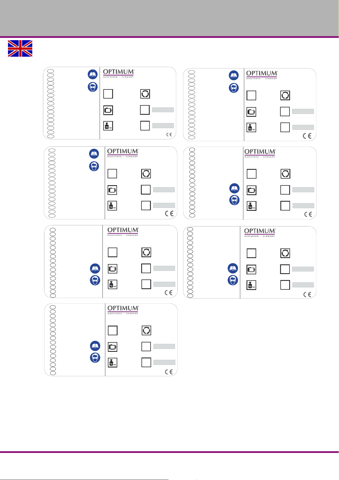
Type plates
Optimum Maschinen
Germany GmbH
Dr.-Robert-Pfleger-Str. 26
D-96103 Hallstadt
300 3263
82 kg
750 W
400 V ~50 Hz
B 26 Pro
2440 U/min
20
NO.
SN
Year
Master Labels
J
DE
GB
ES
FR
IT
CZ
DK
FI
GR
HU
NL
PL
PT
RU
SLO
TR
Säulenbohrmaschine
Søjleboremaskine
Pylväsporakone
Wiertarki
Bormașină
Upright drilling machine
Taladro
Perceuse
Trapano a colonna
Sloupová vrtačka
Επιδαπεδειο Δραπανο
Asztali fúrógép
Boormachine
Máquina de perfuração
Steberni vrtalni stroj
Sütunlu Matkap
optimum-maschinen.de
Master Labels
Optimum Maschinen
Germany GmbH
Dr.-Robert-Pfleger-Str. 26
D-96103 Hallstadt
300 3231
66 kg
750 W
230 V ~50 Hz
B 23 Pro
2440 U/min
20
NO.
SN
Year
J
Tischbohrmaschine
Bench drilling machine
Taladro de sobremesa
Perceuse modèle établi
Trapani da banco
Stolní vrtačka
Table boremaskine
Penkkiporakone
Asztali fúrógép
Boormachine tafelmodel
Wiertarki
Engenho de Furarde Bancada
Masina de gaurit
Bänkborrmaskin
Namizni vrtalni stroj
Sütunlu Matkap
ΔΡΑΠΑΝΟ ΠΑΓΚΟΥ
DE
GB
ES
FR
IT
CZ
DK
FI
GR
HU
NL
PL
PT
RO
SE
SK
TR
optimum-maschinen.de
Optimum Maschinen
Germany GmbH
Dr.-Robert-Pfleger-Str. 26
D-96103 Hallstadt
300 3171
39 kg
500 W
230 V ~50 Hz
B 17 Pro
2520 U/min
20
NO.
SN
Year
Master Labels
J
Tischbohrmaschine
Bench drilling machine
Taladro de sobremesa
Perceuse modèle établi
Trapani da banco
Stolní vrtačka
Table boremaskine
Penkkiporakone
Asztali fúrógép
Boormachine tafelmodel
Wiertarki
Engenho de Furarde Bancada
Masina de gaurit
Bänkborrmaskin
Namizni vrtalni stroj
Sütunlu Matkap
ΔΡΑΠΑΝΟ ΠΑΓΚΟΥ
DE
GB
ES
FR
IT
CZ
DK
FI
GR
HU
NL
PL
PT
RO
SE
SK
TR
optimum-maschinen.de
Optimum Maschinen
Germany GmbH
Dr.-Robert-Pfleger-Str. 26
D-96103 Hallstadt
300 3333
135 kg
1,1 kW
400 V ~50 Hz
B 33 Pro
1810 U/min
20
NO.
SN
Year
Master Labels
DE
GB
ES
FR
IT
CZ
DK
FI
GR
HU
NL
PL
PT
RU
SLO
TR
Säulenbohrmaschine
Søjleboremaskine
Pylväsporakone
Wiertarki
Bormașină
Upright drilling machine
Taladro
Perceuse
Trapano a colonna
Sloupová vrtačka
Επιδαπεδειο Δραπανο
Asztali fúrógép
Boormachine
Máquina de perfuração
Steberni vrtalni stroj
Sütunlu Matkap
optimum-maschinen.de
Optimum Maschinen
Germany GmbH
Dr.-Robert-Pfleger-Str. 26
D-96103 Hallstadt
301 1233
75 kg
750 W
400 V ~50 Hz
B 23 Pro Vario
4940 U/min
20
NO.
SN
Year
J
Master Labels
Tischbohrmaschine
Bench drilling machine
Taladro de sobremesa
Perceuse modèle établi
Trapani da banco
Stolní vrtačka
Table boremaskine
Penkkiporakone
Επιτραπέζιο Δραπανο
Asztali fúrógép
Boormachine tafelmodel
Wiertarki
Engenho de Furarde Bancada
Masina de gaurit
Bänkborrmaskin
Namizni vrtalni stroj
Sütunlu Matkap
DE
GB
ES
FR
IT
CZ
DK
FI
GR
HU
NL
PL
PT
RO
SE
SK
TR
optimum-maschinen.de
Optimum Maschinen
Germany GmbH
Dr.-Robert-Pfleger-Str. 26
D-96103 Hallstadt
301 1333
140 kg
1,5 kW
400 V ~50 Hz
B 33 Pro Vario
3850 U/min
20
NO.
SN
Year
J
Master Labels
DE
GB
ES
FR
IT
CZ
DK
FI
GR
HU
NL
PL
PT
RU
SLO
TR
Säulenbohrmaschine
Søjleboremaskine
Pylväsporakone
Wiertarki
Bormașină
Upright drilling machine
Taladro
Perceuse
Trapano a colonna
Sloupová vrtačka
Επιδαπεδειο Δραπανο
Asztali fúrógép
Boormachine
Máquina de perfuração
Steberni vrtalni stroj
Sütunlu Matkap
optimum-maschinen.de
Optimum Maschinen
Germany GmbH
Dr.-Robert-Pfleger-Str. 26
D-96103 Hallstadt
301 1263
90 kg
750 W
400 V ~50 Hz
B 26 Pro Vario
4000 U/min
20
NO.
SN
Year
J
Master Labels
DE
GB
ES
FR
IT
CZ
DK
FI
GR
HU
NL
PL
PT
RU
SLO
TR
Säulenbohrmaschine
Søjleboremaskine
Pylväsporakone
Wiertarki
Bormașină
Upright drilling machine
Taladro
Perceuse
Trapano a colonna
Sloupová vrtačka
Επιδαπεδειο Δραπανο
Asztali fúrógép
Boormachine
Máquina de perfuração
Steberni vrtalni stroj
Sütunlu Matkap
optimum-maschinen.de
OPTIMUM
MASCHINEN - GERMANY
Safety
Version 2.0.2 2014-11-04 Page 7Original operating instructions
B17Pro | B23Pro | B26Pro | B33Pro GB
Page 8
OPTIMUM
MASCHINEN - GERMANY
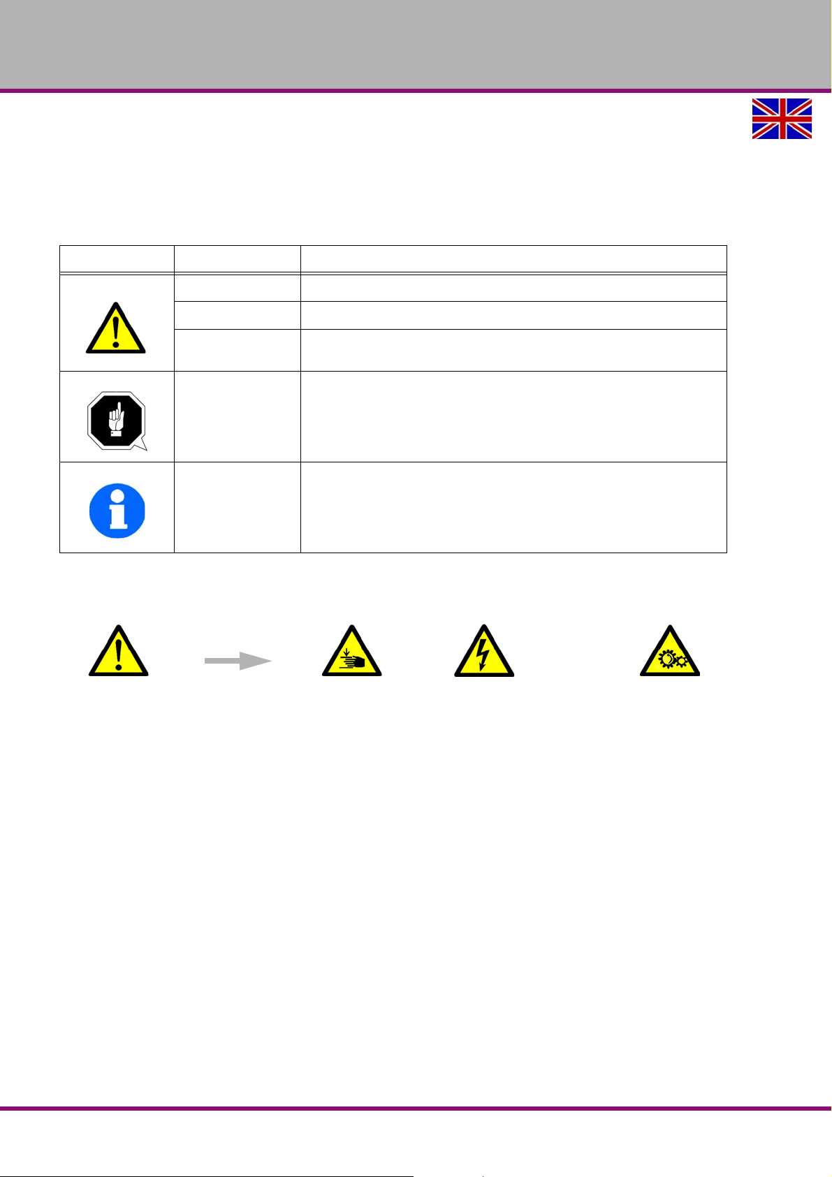
1.1 Safety instructions (warning notes)
1.1.1 Classification of hazards
We classify the safety instructions into different levels. The table below gives an overview of the
classification of symbols (pictograms) and signal words for the specific danger and its (possible)
consequences.
Pictogram Signal word Definition/Consequences
DANGER!
WARNING!
CAUTION!
ATTENTION!
INFORMATION
In case of specific dangers, we replace the pictogram by
Imminent danger that will cause severe injury of death to the staff.
A danger that might cause severe injury to the staff or can lead to death.
Danger of unsafe procedure that might cause injury to the staff or prop-
erty damages.
Situation that could cause damage to the drilling machine and products
and other types of damage.
No risk of injury to the staff.
Application tips and other important or useful information and notes.
No dangerous or harmful consequences for the staff or objects.
or
general danger by a warning of injuries to hands, hazardous electrical
voltage,
rotating parts.
B17Pro | B23Pro | B26Pro | B33ProGB
Version 2.0.2 2014-11-04Page 8 Original operating instructions
Safety
Page 9
1.1.2 Other pictograms
OPTIMUM
MASCHINEN - GERMANY
Activation forbidden! Disconnect the
mains plug!
Use protective boots! Use protective suit! Protect the environ-
Use protective
glasses!
ment!
Use ear protection! Use protective gloves!
Contact address
1.2 Intended use
The drilling machine is designed and manufactured for holes in cold metals or other non flammable materials or that not constitute a health hazard using a rotating filing-stripping tool that
has a number of grooves for collecting the filings.
The drilling machine may only be operated with tools whose cutting edge arrangement forms a
force couple around the rotational axis in engagement.
A quick-action drill chuck for holding the tools is provided as standard. The drilling machine
must only be used with a quick-action drill chuck.
If the drilling machine is used in any way other than described above, modified without the
approval of the company Optimum Maschinen Germany GmbH then the drilling machine is
being used improperly.
We will not be held liable for any damages resulting from any operation which is not in accordance with the intended use.
We expressly point out that the guarantee or CE conformity will expire due to any constructive
technical or procedural changes which had not been performed by the company Optimum
Maschinen Germany GmbH.
It is also part of intended use that you
observe the limits of the drilling machine, "Technical data“ on page 19
the operating manual is observed,
inspection and maintenance instructions are observed.
Operations
not in accordance with
intended use!
WARNING!
Extremely severe injuries.
It is forbidden to make any modifications or alternations to the operation values of the
drilling machine! They could endanger the staff and cause damage to the drilling
machine.
INFORMATION
The drilling machine B23Pro Vario, B26Pro Vario, B33Pro Vario is built according to the
standard DIN EN 55011 class A.
WARNING!
The class A (machine tools) is not intended to be used in residential facilities, where the
power is supplied via a public low voltage supply system. In these areas it may possibly
Safety
Version 2.0.2 2014-11-04 Page 9Original operating instructions
B17Pro | B23Pro | B26Pro | B33Pro GB
Page 10
OPTIMUM
MASCHINEN - GERMANY
be difficult to guarantee electromagnetic compatibility due to lead bound as well as
emitted interferences.
ATTENTION!
If the drilling machine is not used as intended or if the safety directives or the operating
instructions are ignored the liability of the manufacturer for any damages to persons or
objects resulting hereof is excluded and the claim under guarantee is becoming null and
avoid!
1.3 Reasonably foreseeable misuse
Any other use as the one determined under the "Intended use" or any use beyond the
described use shall be deemed as not in conformity and is forbidden.
Any other use has to be discussed with the manu fa ct ur er .
It is only allowed to process metal, cold and non-inflammable materials with the drilling
machine.
In order to avoid misuses it is necessary to read and understand the operating instructions
before the first commissioning.
The operating staff has to be qualified.
1.3.1 Avoiding misuses
Use of suitable cutting tools.
Adapting the speed adjustment and feed to the material and workpiece.
Clamp workpieces firmly and vibration-free.
ATTENTION!
The workpiece is always to be fixed by a machine vice, jaw chuck or by another
appropriate clamping tool such as for the clamping claws.
WARNING!
Risk of injury caused by workpieces flying off.
Clamp the workpiece in the machine vice. Make sure that the workpiece is firmly clamped in the
machine vice resp. that the machine vice is firmly clamped on the machine table.
Use cooling and lubricating agents to increase the durability of the tool and to improve the
surface quality.
Clamp the cutting tools and workpieces on clean clamping surfaces.
Sufficiently lubricate the machine.
Correctly adjust the bearing clearance and the guidings.
It is recommended:
Insert the drill in a way that it is exactly positioned between the three clamping jaws of the
quick action chuck.
When drilling make sure, that
the suitable speed is set depending on the diameter of the drill,
the pressure must only be such that the drill can cut without load
in case of too strong pressure the drill will get worn early or even might break resp. get
jammed in the hole. If the drill gets jammed, immediately stop the main motor by pressing
the emergency stop button.
for hard materials, e.g. steel, use commercial cooling / lubricating agents,
generally always drive the turning spindle out of the workpiece.
B17Pro | B23Pro | B26Pro | B33ProGB
Version 2.0.2 2014-11-04Page 10 Original operating instructions
Safety
Page 11
OPTIMUM
MASCHINEN - GERMANY
1.4 Possible dangers caused by the drilling machine
The drilling machine has undergone a safety inspection (analysis of danger with assessment of
risks). It has been designed and built on the basis of this analysis using the latest technological
advances.
Nevertheless, there is a residual risk as the drilling machine operates with
at high speeds,
rotating parts,
with electrical voltages and currents.
We have used construction resources and safety techniques to minimize the health risk for the
staff resulting from these hazards.
If the drilling machine is used and maintained by the staff who are not duly qualified, there may
be a risk resulting from incorrect or unsuitable maintenance of the drilling machine.
INFORMATION
All staff involved in assembly, commissioning, operation and maintenance, must
be duly qualified,
strictly follow these operating instructions.
In the event of intended use
there may be a risk to the staff,
there may be a risk to the machine and other material values,
the correct function of the drilling machine may be affected.
Disconnect the drilling machine whenever cleaning or maintenance work is being carried out.
WARNING!
The drilling machine may only be used with functional safety devices.
Disconnect the drilling machine immediately, whenever you detect a failure in the safety
devices or when they are not fitted!
All additional devices installed by the operator have to be equipped with the prescribed
safety devices.
This is your responsibility being the operating company!
"Safety devices“ on page 13
1.5 Qualification of the staff
1.5.1 Target group
This manual is addressed to
the operating companies,
the operators,
the staff for maintenance works.
Therefore, the warning notes refer to both, operation and maintenance staff of the drilling
machine.
Determine clearly and explicitly who will be responsible for the different activities on the
machine (operation, maintenance and repair).
Unclear responsibilities constitute a safety risk!
Always disconnect plug of the drilling machine from the electrical power supply. This will pre-
vent it from being used by unauthorized staff.
Operator
The operator is instructed by the operating company about the assigned tasks and possible
risks in case of improper behaviour. Any tasks which need to be performed beyond the opera-
Safety
Version 2.0.2 2014-11-04 Page 11Original operating instructions
B17Pro | B23Pro | B26Pro | B33Pro GB
Page 12
OPTIMUM
MASCHINEN - GERMANY
tion in the standard mode must only be performed by the operator if it is indicated in these
instructions and if the operating company expressively commissioned the operator.
Electrical specialist
Due to his professional training, knowledge and experience as well as his knowledge of respective standards and regulations the electrical specialist is able to perform works on the electrical
system and to recognise and avoid any possible dangers himself.
The electrical specialist is specially trained for the working environment in which he is working
and knows the relevant standards and regulations.
Specialist staff
Due to its professional train ing, knowledge and experience as well as his knowledge of relevant regulations the specialist staff is able to perform the assigned tasks and to recognise and
avoid any possible dangers himself.
Instructed persons
Instructed persons were instructed by the operating company about the assigned tasks and any
possible risks in case of improper behaviour.
1.5.2 Authorized staff
WARNING!
Inappropriate operation and maintenance of the drilling machine constitutes a danger for
the personnel, objects and the environment.
Only authorized staff may operate the drilling machine !
Persons authorized to operate and maintain should be trained technical staff and instructed by
the ones who are working for the operating company and for the manufacturer.
The operating company must
train the staff,
instruct the staff in regular intervals (at least once a year) on
- all safety standards that apply to the machine,
- the operation,
- accredited technical guidelines,
check staff‘s state of knowledge,
document the trainings/instructions,
require staff to confirm participation in training/instructions by means of a signature,
check whether the staff is working safety- and risk-conscious and observe the operating
instructions.
The operator must
have obtained a training regarding the handling of the drilling machine,
know the function and mode of action,
before taking the machine in operation
- have read and understood the operating instructions,
- be familiar with all safety devices and instructions.
For work on the following parts there are additional requirements:
Electric components or operating materials: Must only be performed by a qualified electri-
cian or person working under the instructions and supervision of a qualified electrician.
Obligations of the operating company
Obligations of the operator
Additional requirements regarding the qualification
B17Pro | B23Pro | B26Pro | B33ProGB
Version 2.0.2 2014-11-04Page 12 Original operating instructions
Safety
Page 13
OPTIMUM
MASCHINEN - GERMANY
Before starting work on electrical parts or operating agents, following measures are to be
performed in the following order.
- Disconnect all poles.
- Secure against switching on.
- Check if the machine is zero potential.
1.6 Operator positions
The operator’s position is in front of the drilling machine.
INFORMATION
The mains plug of the drilling machine has to be freely accessible.
1.7 Safety measures during operation
CAUTION!
Risk by inhaling health hazardous dusts and fogs.
Depending on the materials which need to be treated and the agents which are used,
dusts and fogs may be generated which endanger your health.
Make sure that the generated health hazardous dusts and fogs are safely sucked-off at
the place of origin and that they are dissipated or filtered. To do so, use a suitable
extraction unit.
CAUTION!
Risk of fire and explosion by using inflammable materials or cooling-lubricating agents.
Before processing inflammable materials (e.g. aluminium, magnesium) or using
inflammable auxiliary materials (e.g. spirit) it is necessary to take additional preventive
measures in order to safely avoid health risks.
1.8 Safety devices
Use the drilling machine only with properly functioning safety devices.
Stop the drilling machine immediately if there is a failure on the safety device or if it is not func-
tioning for any reason.
It is your responsibility!
If a safety device has been activated or has failed, the drilling machine must only be used if you
have removed the cause of the failure,
have verified that there is no danger resulting for the staff or objects.
WARNING!
If you bypass, remove or deactivate a safety device in any other way, you are
endangering yourself and other staff working with the drilling machine. The possible
consequences are:
injuries may occur due to workpiece or parts of workpieces flying off,
contact with rotating parts,
a fatal electrocution,
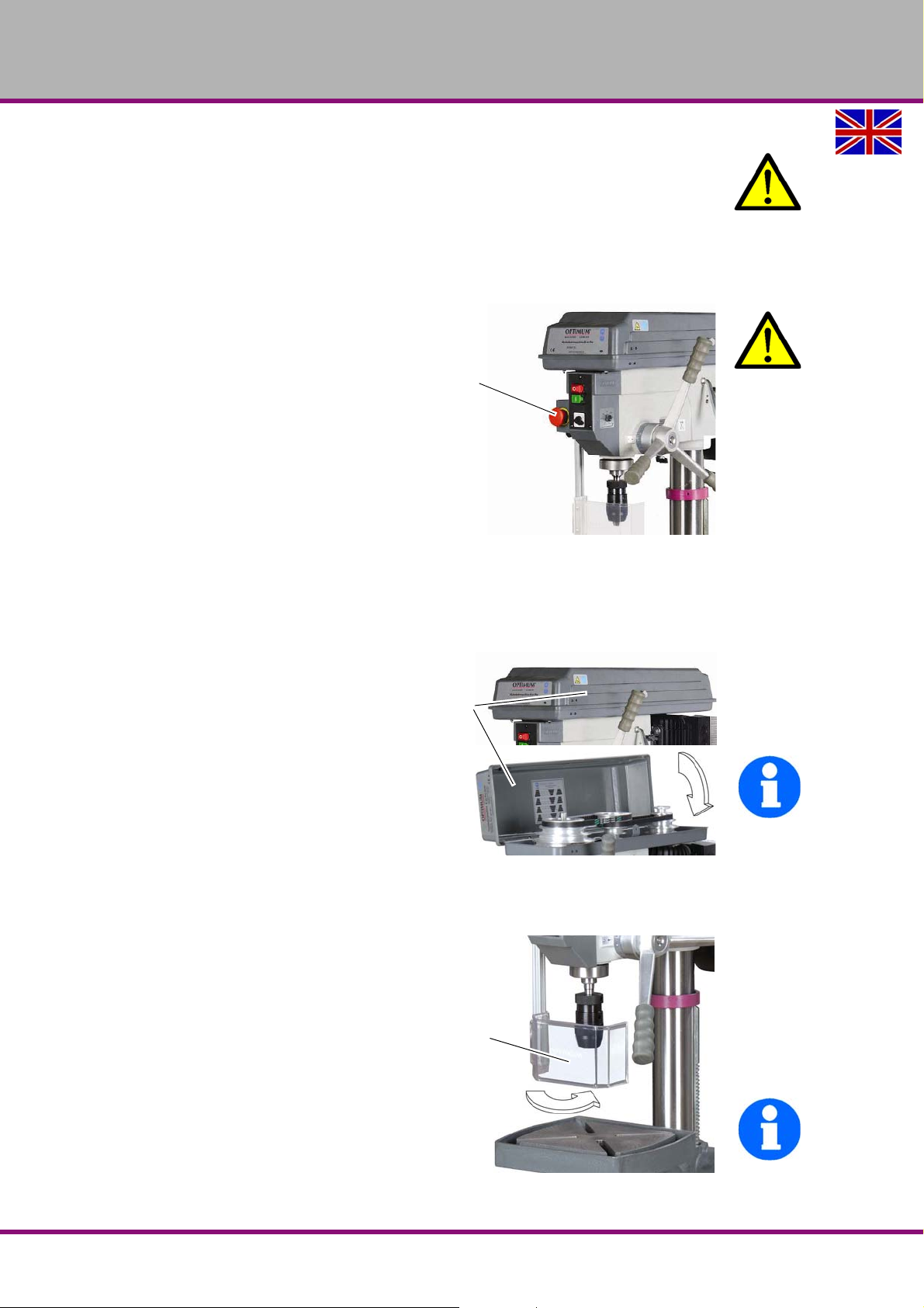
The drilling machine machine includes the following safety devices:
an EMERGENCY STOP push button,
a protective cover of the pulleys with positioning switch,
a drill chuck protection with positioning switch,
a drilling table with T-slots to fix the workpiece or a vice.
Safety
Version 2.0.2 2014-11-04 Page 13Original operating instructions
B17Pro | B23Pro | B26Pro | B33Pro GB
Page 14
OPTIMUM
EMERGENCY-
STOP button
Protective cover
Drill chuck
protection
MASCHINEN - GERMANY
WARNING!
The separating protective covers which are made available and delivered together with
the machine are designed to reduce the risk of workpieces or fragments of tools or
workpieces flying off at high speed - however, this cannot be completely avoided.
Always work carefully and observe the limit values of your chipping process.
1.9 EMERGENCY-STOP push button
ATTENTION!
Also after actuating the EMERGENCY-
STOP switch, the drilling spindle is
turning - depending on the previously
selected speed - for a few seconds
more.
1.10 Separating protective devices
1.10.1 Covering cap of the pulley
A covering cap for the pulleys is moun ted
on the drilling head.
A switch is integrated in the protective
cover which monitors that the closed
position.
INFORMATION
You cannot start the machine if the protective cover is not closed.
1.10.2 Drill chuck protection
Adjust the protective equipment to the correct
height before you start working.
To do so, detach the clamping screw, adjust
the required height and re-tighten the clamping screw.
A switch is integrated in the fixture of the spindle protection which monitors that the cover is
closed.
INFORMATION
You cannot start the machine if the drill chuck
protection is not closed.
Img.1-1: EMERGENCY-STOP push button
Img.1-2: Protective cover
Img.1-3: Drill chuck protection
B17Pro | B23Pro | B26Pro | B33ProGB
Version 2.0.2 2014-11-04Page 14 Original operating instructions
Safety
Page 15
OPTIMUM
Seats for clamping
blocks
MASCHINEN - GERMANY
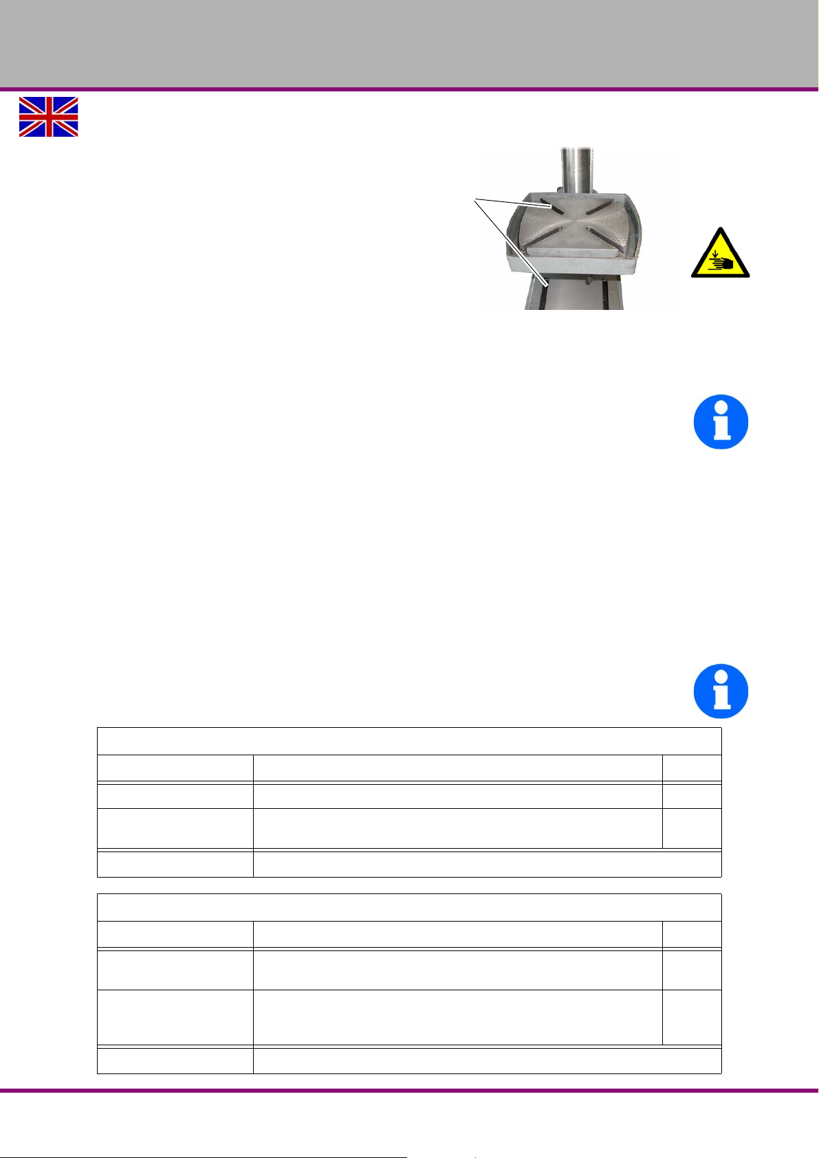
1.11 Drilling table
Seats for T-slots are attached to the drilling table.
WARNING!
Risk of injury due to parts flying off at
high speed. Securely fix the workpiece
on the drilling table.
Img.1-4: Drilling table
1.12 Prohibition, warning and mandatory signs
INFORMATION
All warning signs must be legible. Check them regularly.
1.13 Safety check
Check the drilling machine at least once per shift. Inform the person responsible immediately of
any damage, defect or change in operating function.
Check all safety devices
at the beginning of each shift (at continuous operation),
once a week (with the machine in operation),
after every maintenance and repair work.
Check that prohibition, warning and information signs and the labels on the driling machine.
are legible (clean them, if necessary),
are complete.
INFORMATION
Use the following table for organizing the checks.
General check
Equipment Check OK
Protective cover Mounted and securely tightened
Signs,
Markings
Date: Checked by (signature):
Functional test
Equipment Check OK
EMERGENCY-STOP
Push button
Drill chuck protection Once the emergency stop button is activated, the bench drilling machine
Date: Checked by (signature):
Installed and legible
After actuating an EMERGENCY STOP push button the drilling machine
must be switched off.
should be switched off. The drilling machine may not start if the drill
chuck protection is open.
Safety
Version 2.0.2 2014-11-04 Page 15Original operating instructions
B17Pro | B23Pro | B26Pro | B33Pro GB
Page 16
OPTIMUM
MASCHINEN - GERMANY
Functional test
Equipment Check OK
Position switch
V-belt cover
Date: Checked by (signature):
When the V-belt cover is opened, the drill must switch off automatically.
The drilling machine may not start if the V-belt cover is open.
1.14 Individual protection gear
For certain work individual protection gear as protective equipment. This includes:
Safety helmet,
Protective goggles or face guard,
Protective g loves,
Safety shoes with steel toe caps,
Ear protection.
Before starting work, make sur e that the presc ribed in dividual protec tion ge ar is availab le in the
workplace.
CAUTION!
Dirty or contaminated personnel protective equipment can cause dis eases.
Clean your individual protection gear
after each use,
regularly, at least once a week.
Personal protective equipment for special works
Protect your face and eyes: wear a safety helmet with facial protection when performing works
where your face and eyes are exposed to hazards.
Use protective gloves when handling pieces with sharp edges.
Use safety shoes when you assemble, disassemble or transport heavy components.
B17Pro | B23Pro | B26Pro | B33ProGB
Version 2.0.2 2014-11-04Page 16 Original operating instructions
Safety
Page 17
OPTIMUM
MASCHINEN - GERMANY
1.15 Safety during operation
We specially point out the specific dangers when working with and on the drilling machine.
WARNING!
Before switching on the drilling machine make sure that there are
no dangers generated for persons,
not cause damage to equipment.
Avoid any risky working practices:
Make sure your work does not endanger anyone.
The instructions mentioned in these operating instructions have to be strictly observed dur-
ing assembly, operation, maintenance and repair.
Do not work on the drilling machine, if your concentration is reduced, for example, because
you are taking medication.
Observe the accident prevention regulations issued by your Employers Liability Insurance
Association or other competent supervisory authority, responsible for your company.
Inform the supervisor about all endangerments or errors.
Use the prescribed personnel protective equipment. Make sure to wear a well-fitting work
suit and, if necessary, a hairnet.
Do not use protective gloves when drilling or milling.
1.16 Safety during maintenance
Inform the operators in good time about any maintenance and repair works.
Report all safety relevant changes and performance details of the drilling machine or their oper-
ational behavior. Document all changes, have the operating instructions updated accordingly
and train machine operators.
1.16.1 Disconnecting and securing the drilling machine
Unplug the main switch before starting any maintenance or repair work. All machine components and hazardous voltages and movements must have been disconnected.
Attach a warning sign on the machine.
1.16.2 Using lifting equipment
WARNING!
The use of unstable lifting and load suspension gear that might break under load can
cause severe injuries or even death.
Check that the lifting and load suspension gear devices
they have sufficient load carrying
and that it is in perfect condition.
Observe the accident prevention regulations issued by your Employers Liability
Insurance Association or other competent supervisory authority, responsible for your
company.
Fasten the loads properly.
Never walk under suspended loads!
Report
changes
and document these
Safety
Version 2.0.2 2014-11-04 Page 17Original operating instructions
B17Pro | B23Pro | B26Pro | B33Pro GB
Page 18

OPTIMUM
MASCHINEN - GERMANY
1.16.3 Mechanical maintenance work
Remove or install protection safety devices before starting any maintenance work and re-install
them once the work has been completed.This includes:
Covers,
Safety indications and warnin g signs,
Earth (ground) connections.
If you remove protective or safety devices, re-fit them immediately after the completing the
work.
Check if they are working properly!
1.17 Accident report
Inform your superiors and Optimum Maschinen Germany GmbH immediately in the event of
accidents, possible sources of danger and any actions which almost led to an accident (near
misses).
There are many possible causes for "near misses".
The sooner they are notified, the faster the causes can be eliminated.
INFORMATION
We point out the specific dangers when performing works with and on the drilling machine
when describing such works.
1.18 Electrical system
"Maintenance“ on page 43
Have the machine and/or the electric equipment checked regularly. Check the electrical system according to DIN EN 60204.
Immediately eliminate all defects such as loose connections, defective wires, etc.
A second person must be present during work on live components to disconnect the power in
the event of an emergency.
Immediately disconnect the drilling machine if there are any anomalies in the power supply!
B17Pro | B23Pro | B26Pro | B33ProGB
Version 2.0.2 2014-11-04Page 18 Original operating instructions
Safety
Page 19
OPTIMUM
MASCHINEN - GERMANY
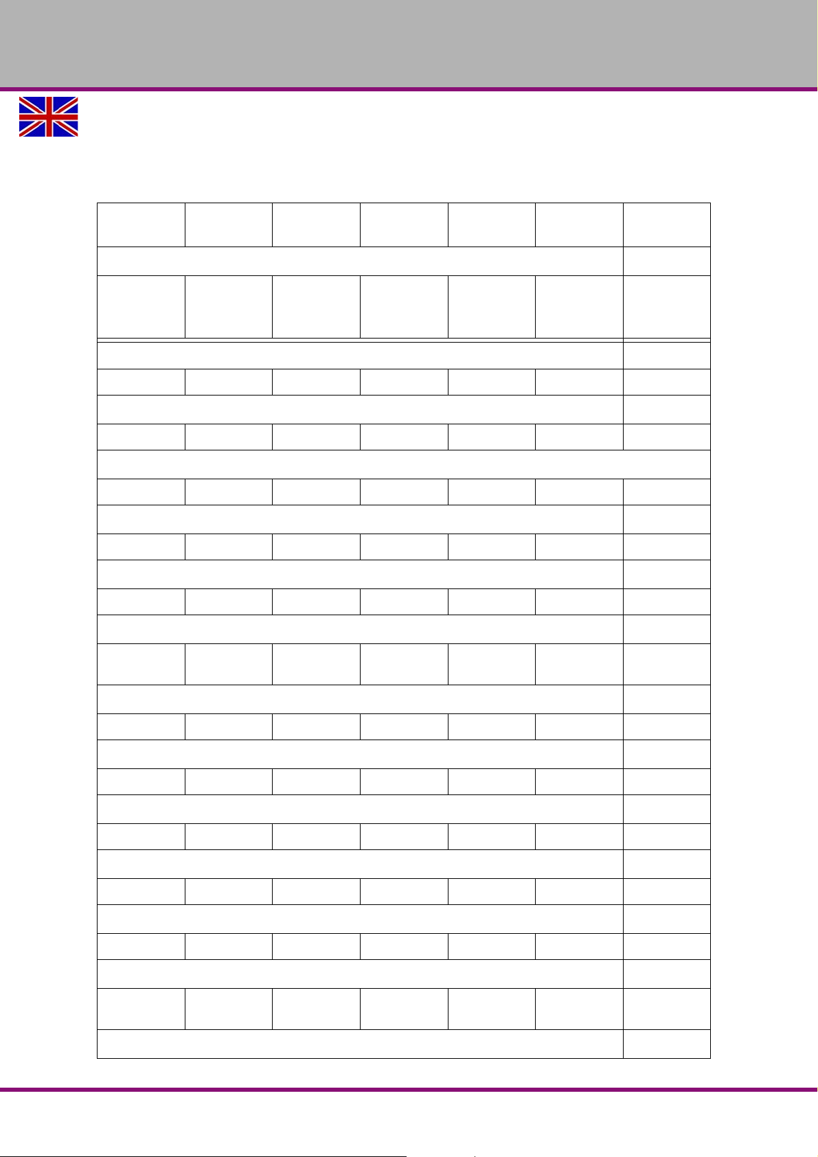
2 Technical data
The following information are the dimensions and indications of weight and the manufacturer‘s
approved machine data.
B17Pro B23Pro
B23Pro
Vario
B26Pro
B26Pro
Vario
B33Pro
2.1 Electrical connection
230V~50 Hz
230V~50 Hz
or
400V~50 Hz
400V~50 Hz 400V~50 Hz 400V~50 Hz 400V~50 Hz 400V~50 Hz
2.2 Power drive motor
500 W 750 W 750 W 750 W 750 W 1.1 KW 1.5 KW
2.3 Drilling capacity in steel S235JR
16mm 25mm 25mm 25mm 25mm 30mm 30mm
2.4 Continuous drilling capacity in steel S235JR
12mm 20mm 20mm 20mm 20mm 25mm 25mm
2.5 Spindle seat
MK2 MK2 MK2 MK3 MK3 MK4 MK4
2.6 T-slots - size
12mm 12mm 12mm 14mm 14mm 14mm 14mm
B33Pro
Vario
2.7 Table size
230 x
220mm
280 x
245mm
280 x
245mm
330 x
290mm
330 x
290mm
475 x
425mm
475 x
425mm
2.8 Spindle stroke
65mm 80mm 80mm 85mm 85mm 120mm 120mm
2.9 Throat depth
152mm 180mm 180mm 210mm 210mm 254mm 254mm
2.10 Machine height
860mm 1012mm 1010mm 1670mm 1670mm 1720mm 1720mm
2.11 Column diameter
Ø 60mm Ø 73mm Ø 73mm Ø 80mm Ø 80mm Ø 92mm Ø 92mm
2.12 Distance spindle - table
max. 325mm max. 425mm max. 425mm max. 720mm max. 720mm max. 695mm max. 695mm
2.13 Distance spindle - stand
max.
530mm
max.
618mm
max.
610mm
max.
1230mm
max.
1230mm
max.
1180mm
max.
1180mm
2.14 Dimension
Technical data
Version 2.0.2 2014-11-04 Page 19Original operating instructions
B17Pro | B23Pro | B26Pro | B33Pro GB
Page 20
OPTIMUM
MASCHINEN - GERMANY
B17Pro B23Pro
600 x 260 x
860 mm
654 x 330 x
1012 mm
B23Pro
Vario
660 x 320 x
1010 mm
B26Pro
700 x 350 x
1670 mm
B26Pro
Vario
710 x 350 x
1670 mm
B33Pro
860 x 480 x
1720 mm
B33Pro
Vario
870 x 480 x
1720 mm
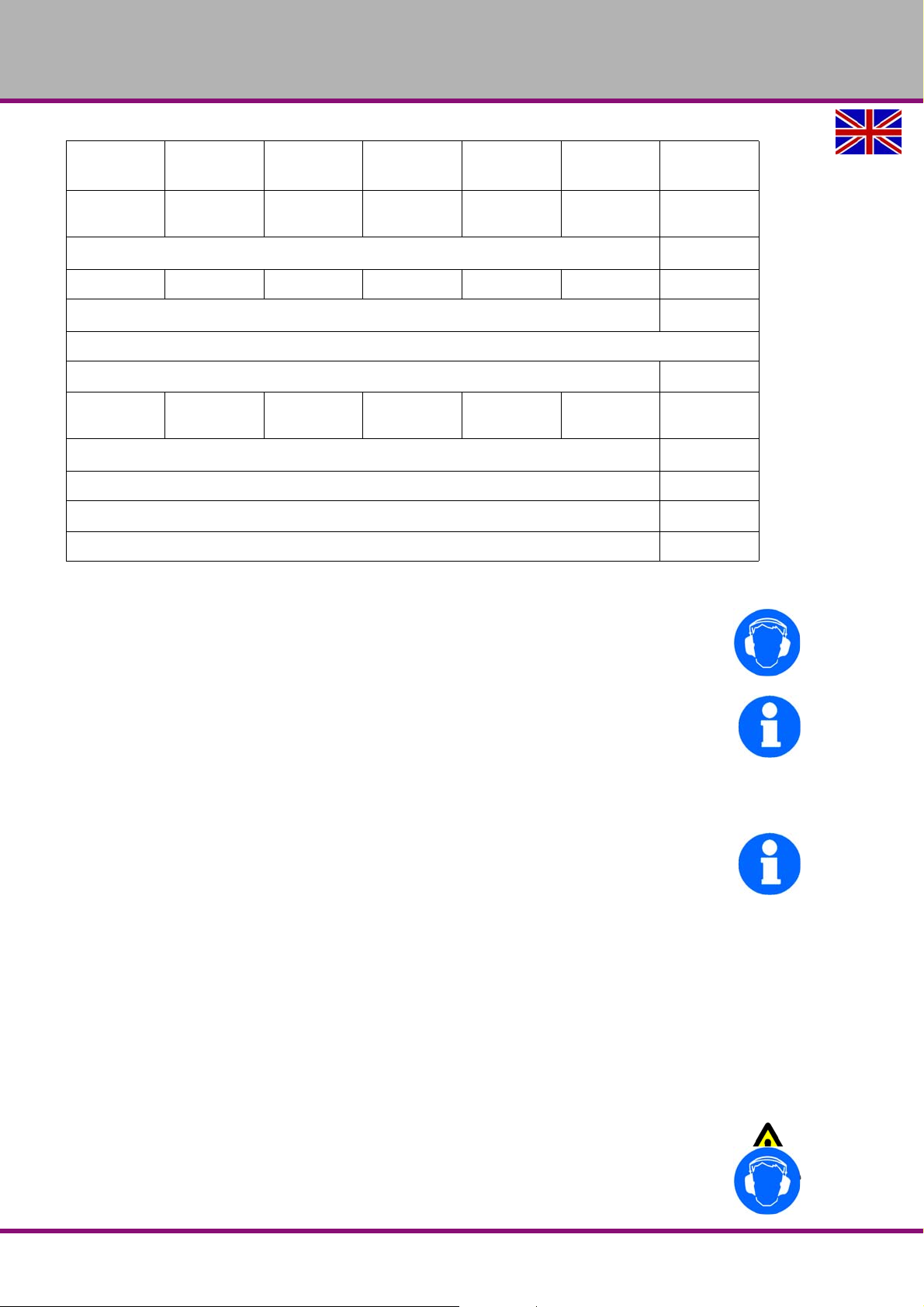
2.15 Weight of machine [kg]
39 66 75 82 90 135 140
2.16 Spindle speeds
"Speed tables“ on page 33
Speed steps
512
12 infinitely
variable
12
2.17 Environmental conditions temperature
5 - 35 °C
Relative humidity
25 - 80 %
2.18 Emissions
The emission of the drilling machine is 73 dB(A) at idle.
If the is installed in an area where various machines are in operation the acoustic influence
immission) on the operator of the drilling machine may exceed 85 dB(A).
12 infinitely
variable
9
9 infinitely
variable
INFORMATION
This numerical value was measured on a new machine under proper operating conditions.
Depending on the age respectively on the wear of the machine it is possible that the noise
behaviour of the machine changes.
Furthermore, the factor of the noise emission is also depending on manufacturing influencing
factors, e.g. speed, material and clamping conditions.
INFORMATION
The mentioned numerical value is the emission level and not necessarily a safe working level.
Though there is a dependency between the degree of the noise emission and the degree of the
noise disturbance it is not possible to use it reliably to determine if further precaution measures
are required or not.
The following factors influence the actual degree of the noise exposure of the operator:
Character istics of the working area, e.g. size or damping behaviour,
Other noise sources, e.g. the number of machines,
Other processes taking place in the proximity and the period of time during which the op-
erator is exposed to the noise.
Furthermore, it is possible that the admissible exposure level might be different fr om country to
country due to national regulations.
This information about the noise emission shall allow the operator of the machine to more easily evaluate the endangering and risks.
CAUTION!
Depending on the overall noise exposure and the basic limit values the machine
operators has to wear an appropriate hearing protection.
B17Pro | B23Pro | B26Pro | B33ProGB
Version 2.0.2 2014-11-04Page 20 Original operating instructions
Technical data
Page 21

OPTIMUM
MASCHINEN - GERMANY
We generally recommend to use a noise protection and a hearing protection.
Technical data
Version 2.0.2 2014-11-04 Page 21Original operating instructions
B17Pro | B23Pro | B26Pro | B33Pro GB
Page 22
OPTIMUM
MASCHINEN - GERMANY
3 Assembly
INFORMATION
The drilling machine comes disassembled due to packaging reasons.
Before commissioning, the drilling machine has to be assembled.
3.1 Scope of delivery
When the machine is delivered, check immediately that the drilling machine has not been damaged during transport and that all components are included. Remove all parts from the cardboard box and compare them with the following list.
Drill head
Drilling table
Base
Upright component (table support pre-assembled)
RÖHM quick-action drill chuck
Clamping lever
Crank han dle
Levers for spindle sleeve feed
Operating manual
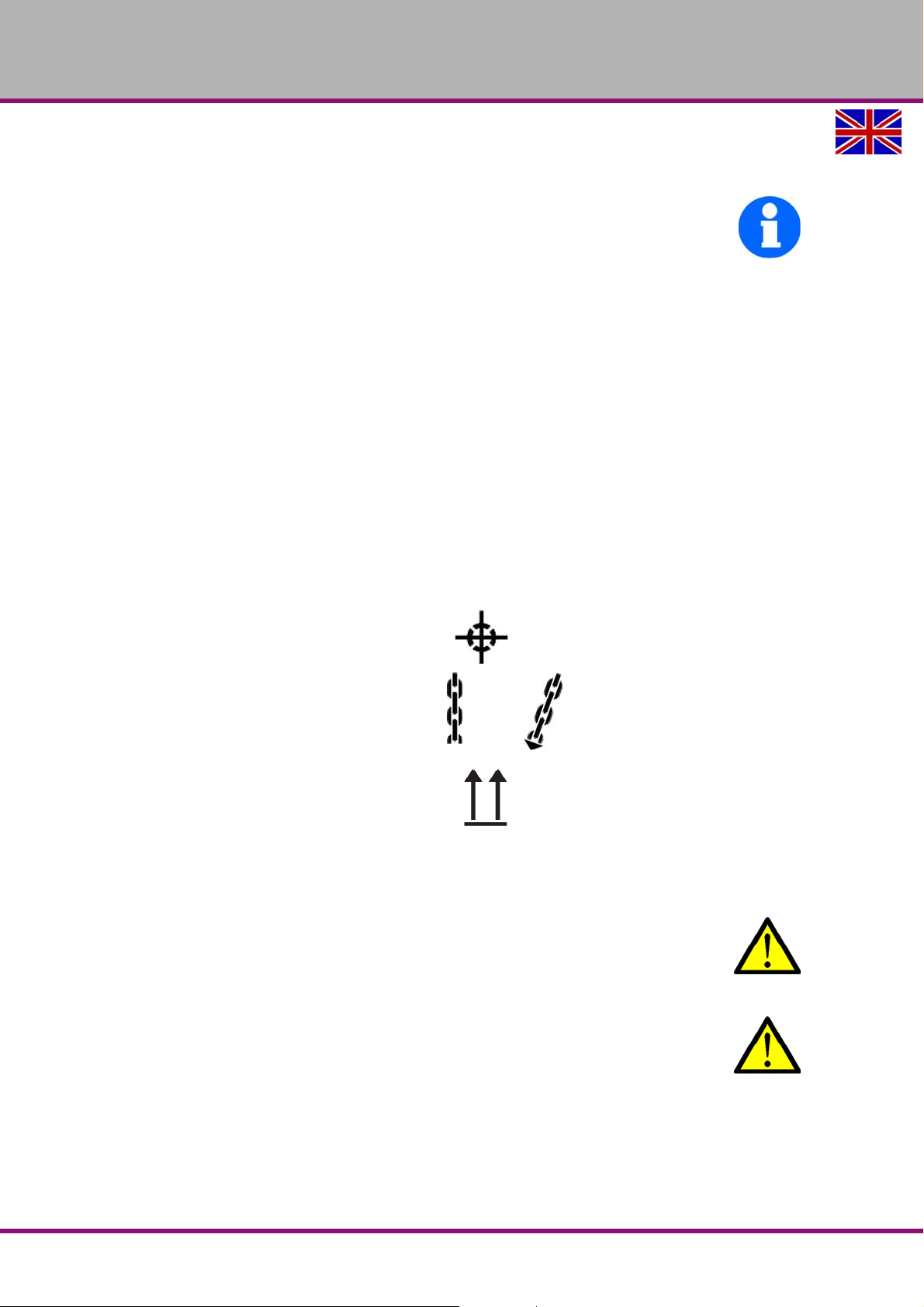
3.2 Transport
Centres of gravity
Load suspension point
(marking the positions for the
attachment position gear)
Prescribed transportation position
(Marking of the top surface)
Means of transport to be used
Weights
WARNING!
Severe or fatal injuries may occur if parts of the machine tumble or fall down from the
forklift truck or from the transport vehicle. Follow the instructions and information on
the transport case.
WARNING!
The use of unstable lifting and load suspension gear that might break under load can
cause severe injuries or even death.
Check that the lifting and load suspension gear has sufficient load capacity and that it is
in perfect condition. Observe the accident prevention regulations issued by your
Employers Liability Insurance Association or other competent supervisory authority,
responsible for your company.
Fasten the loads properly. Never walk under suspended loads!
B17Pro | B23Pro | B26Pro | B33ProGB
Version 2.0.2 2014-11-04Page 22 Original operating instructions
Assembly
Page 23
OPTIMUM
MASCHINEN - GERMANY
3.3 Storage
ATTENTION!
In case of wrong and improper storage electrical and mechanical machine components
might get damaged and destroyed.
Store packed and unpacked parts only under the intended environmenta l conditions.
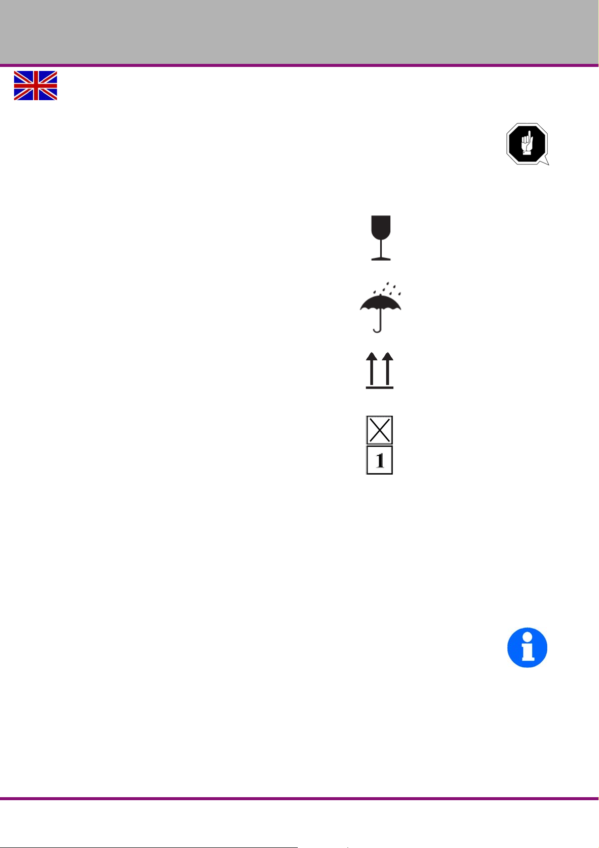
Follow the instructions and information on the transport case:
Fragile goods
(Goods require careful handling)
Protect against moisture and humid environ m en t
"Environmental conditions temperature“ on page 20
Prescribed position of the packing case
(Marking of the top surface - arrows pointing to the
top)
Maximum stacking height
Example:not stackable - do not stack a second
packing case on top of the first one.
Consult Optimum Maschinen Germany GmbH if the machine and accessories are stored for
more than three months or are stored under different environmental conditions than those given
here.
3.4 Installation and assembly
3.4.1 Requirements to the installation site
Organize the working area around the drilling machine according to the local safety regulations.
INFORMATION
In order to attain good functionality and a high processing accuracy as well as a long durability
of the machine the installation site should fulfil certain criteria.
Please observe the following points:
The device must only be installed and operated in a dry and well-ventilated place.
Avoid places nearby machines generating chips or dust.
The installation site must be fr ee from vibrations also at a distance of presses, planing
machines, etc.
The substructure must be suitable for the drilling machine. Also make sure that the floor has
sufficient load bearing capacity and is level.
The substructure must be prepared in a way that possibly used coolant cannot penetrate
into the floor.
Assembly
Version 2.0.2 2014-11-04 Page 23Original operating instructions
B17Pro | B23Pro | B26Pro | B33Pro GB
Page 24
OPTIMUM
Screw
Retaining ring
Toothed rack
Drill column
Base
MASCHINEN - GERMANY
Any parts sticking out such as stops, handles, etc. have to be secured by measures taken
by the customer if necessary in order to avoid endangerment of persons.
Provide sufficient space for the staff preparing and operating the machine and transporting
the material.
Also consider that the machine is accessible for setting and maintenance works.
Provide for sufficient illumination (Minimum value: 500 lux, measured at the tool tip). At little
intensity of illumination an additional illumination has to be ensured e.g. by means of a separate workplace lamp.
INFORMATION
The mains plug of the drilling machine has to be freely accessible.
3.4.2 Assembly
WARNING!
Danger of crushing when assembling and installing the machine components.
"Qualification of the staff“ on page 11
The drilling machine must be installed by at least 2 people, because various elements
and individual parts have to be sustained and joined during assembly.
INFORMATION
The following description of the assembly refers to the B26Pro drilling machine. It has been
chosen for description of the following operations because of its close similarity with the drilling
machines.
B17Pro
B23Pro
B33Pro
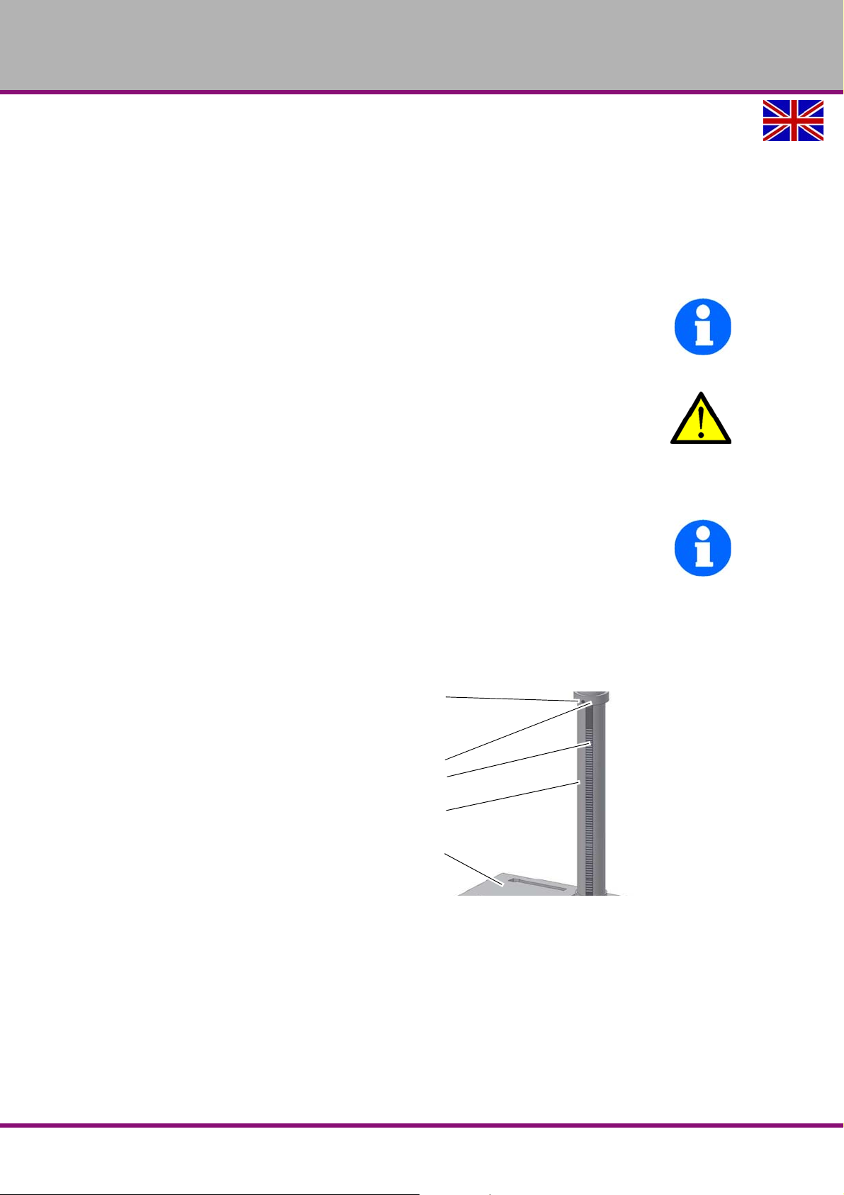
Mounting of base and drill column
Position the base on the floor and
attach the column to the base. Fastening screws for the drilling pillar have
been provided on the base.
Loosen the screw on the retaining ring
and remove the retaining ring and
toothed rack.
Img.3-1: Assembly of the base
B17Pro | B23Pro | B26Pro | B33ProGB
Assembly
Version 2.0.2 2014-11-04Page 24 Original operating instructions
Page 25
OPTIMUM
Toothed rack
Clamping lever
Drilling table
support
Drill head
Lever
Spindle sleeve
lever
Drill upright
Drilling table
Clamping lever
MASCHINEN - GERMANY
Mounting of the drilling table support
Position the worm gear in the support
of the drilling table.
Adjust the toothed rack within the drill-
ing table support in a way that the
teeth of the toothed rack cam into the
spiral wheel of the support for the drilling table support .
Img.3-2: Mounting of the drilling table support
INFORMATION
The longer untoothed end of the rack must point upward.
Push the drilling table support with the toothed rack on the drill column.
Push the supporting ring onto the upright and the rack.
Tighten the screw of the supporting ring slightly. Make sure that the drilling table support
still can be easily turned around the upright.
Attach the clamping lever for drilling table fastening.
Fitting the drill head
Place the drill head on the drill upright
and turn it until it is aligned with the
base. Immobilise the drill head with the
two headless screws in the drill head
over the toothed rack.
Screw in the 3 levers of the spindle
sleeve feed and attach the crank of the
table height adjustment.
Img.3-3: B26Pro
Insert the drilling table in the drilling
table support and clamp it with the
clamping lever.
Img.3-4: B26Pro
Assembly
Version 2.0.2 2014-11-04 Page 25Original operating instructions
Fitting the quick-action drill chuck
"Assembly quick- action drill chuck“ on page 38
B17Pro | B23Pro | B26Pro | B33Pro GB
Page 26
OPTIMUM
Fixture
Setting screw
Aluminium profile
including mounted
safety screen
Hexagon socket
screw
Locking washer
Aluminium profile
Setting screw
MASCHINEN - GERMANY
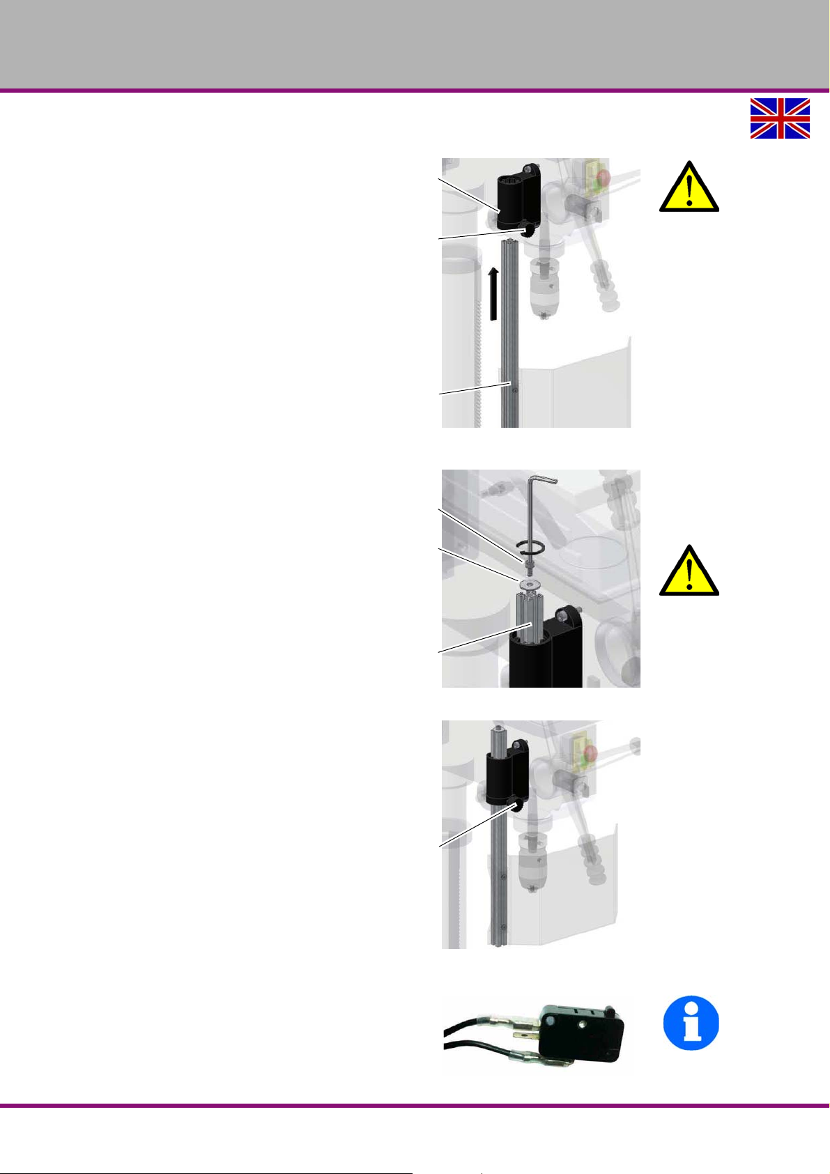
Assembly of the drill chuck protection
WARNING!
Never operate drilling machines without
drill chuck protection.
1. Shift the aluminium profile including the
mounted safety screen (plastic screen)
into the fixture which is mounted on the
drilling head.
2. After assembly of the aluminium profile
screw down the setting screw.
3. Screw the hexagon socket screw with
the locking washer into the aluminium
profile.
Img.3-5: Assembly-1
WARNING!
Make sure that the hexagon socket screw
and the locking washer are mounted and
tightly screwed. Otherwise the aluminium
profile would slide out of the fixture when
the setting screw is screwed off.
4. Make sure that the setting screw shows
to the front after assemblyand if the drill
chuck protection isclosed.
Img.3-6: Assembly-2
INFORMATION
A switch is integrated in the fixture of the drill chuck protection which monitors the closed position. It is not possible to
start the machine until the drill chuck protection is closed.
B17Pro | B23Pro | B26Pro | B33ProGB
Img.3-7: Assembly-3
Assembly
Version 2.0.2 2014-11-04Page 26 Original operating instructions
Page 27
OPTIMUM
Through-bore
Arrow sign
Through-bore
Arrow sign
MASCHINEN - GERMANY
3.5 Installation
Check the horizontal orientation of the base of the drilling machine with a spirit level.
Fix the foot of the drilling machine to the substructure with the provided through-holes.
The installation site must be designed in accordance with ergonomic workplace requirements.
ATTENTION!
Tighten the setscrews on the drilling machine only until it is firmly secured and can
neither move during operation nor be turned over.
If the setscrews are too tight and the base is uneven, the stand of the drilling machine may
break.
3.5.1 Fixing
In order to provide for the necessary stability of the bench drill machine and the upright drilling
machine it is necessary to firmly bolt the base of the machine to the subsurface.
We recommend you to use shear connector c artr i dg es resp . he av y- du ty an ch or s.
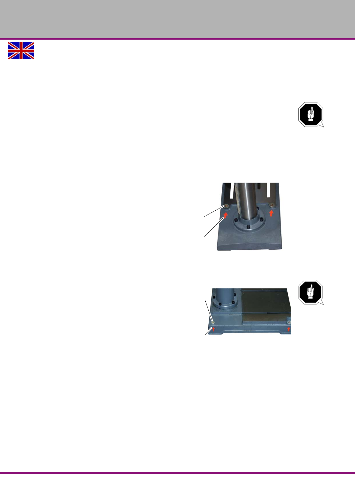
Fix the foot of the drilling machine to the
substructure with the provided thro ug h holes.
The Through-bore are marked with
arrows on the machine base.
ATTENTION!
Tighten the fixing screws of the drilling
machine only as much that it is safely
fixed and cannot break away or tilt over.
If the fixing screws are too tight in particular
in connection with an uneven substructure it
may result in a broken stand.
Img.3-8: Marking of the fixing points of the bench drill
machines
Img.3-9: Marking of the fixing points of the upright
drilling machines
Assembly
Version 2.0.2 2014-11-04 Page 27Original operating instructions
B17Pro | B23Pro | B26Pro | B33Pro GB
Page 28
OPTIMUM
MASCHINEN - GERMANY
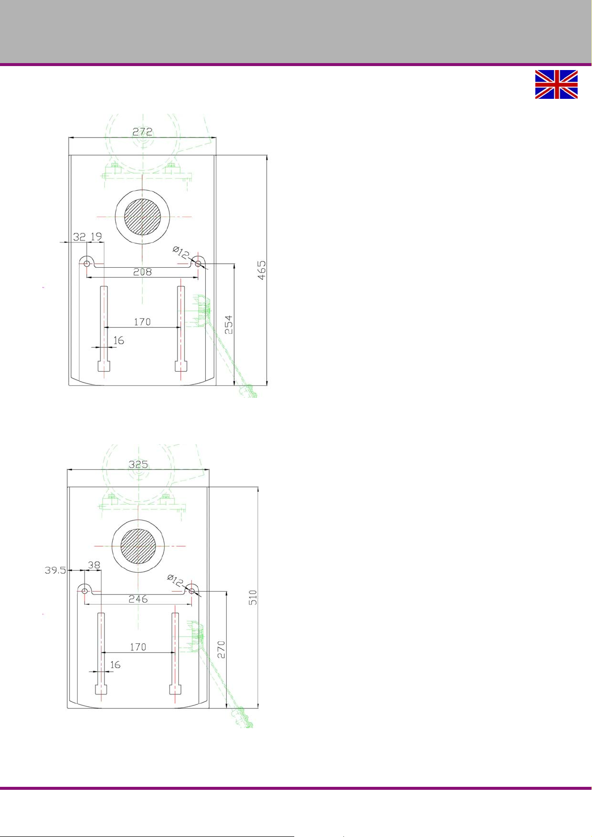
B23Pro, B23Pro Vario
Img.3-10: Fixing of foot B23Pro
B26Pro, B26Pro Vario
Img.3-11: Fixing of foot B26Pro
B17Pro | B23Pro | B26Pro | B33ProGB
Assembly
Version 2.0.2 2014-11-04Page 28 Original operating instructions
Page 29
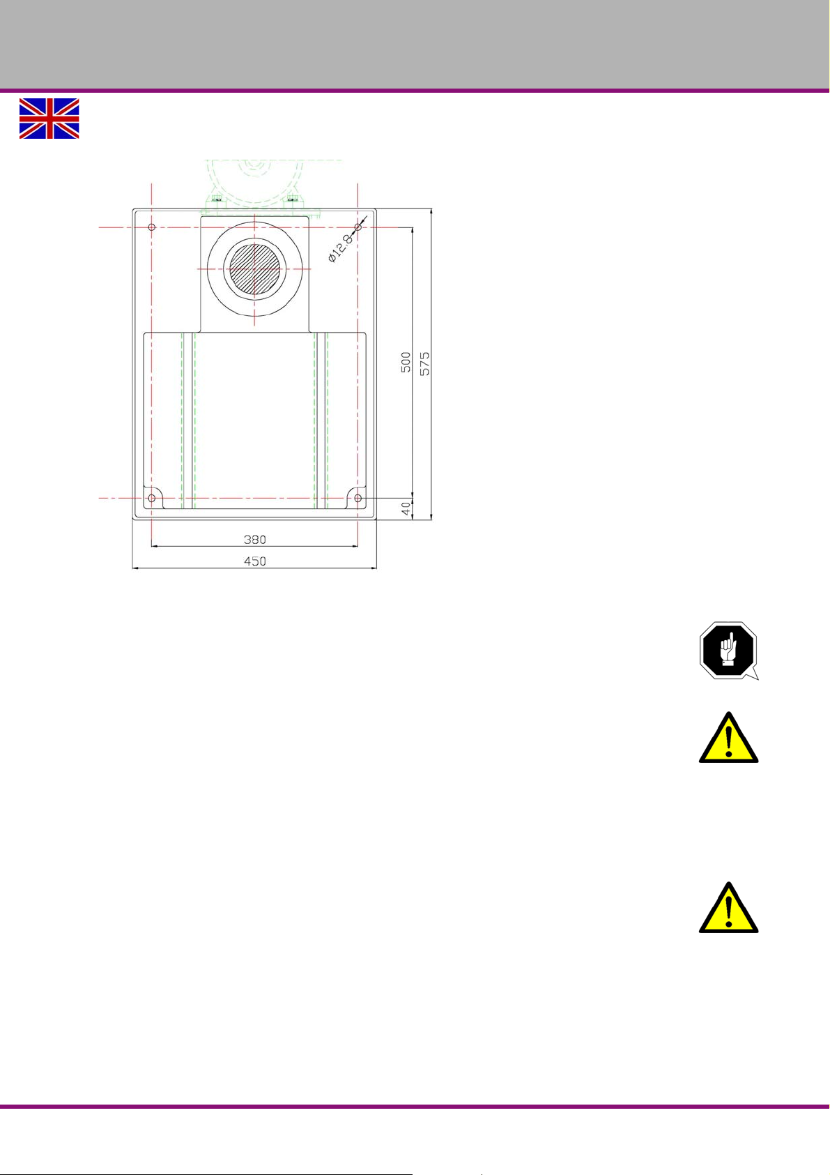
B33Pro, B33Pro Vario
OPTIMUM
MASCHINEN - GERMANY
Img.3-12: Fixing of foot B33Pro
3.6 First commissioning
ATTENTION!
Before commissioning the machine check all screws, fixtures resp. safety devices and
tighten up the screws if necessary!
WARNING!
Risk by using improper workpiece clamping materials or by operating the machine with
inadmissible speed.
Only use the clamping materials (e.g. drill chuck) which had been delivered togetherwith
the machine or as optional equipment offered by OPTIMUM.
Use the working clamping materials only in the provided admissible speed range.
Workpiece clamping materials must only be modified according to the recommendations
of OPTIMUM or of the clamping material manufacturer.
WARNING!
When first commissioning the drilling machine by inexperienced staff you endanger
people, the machine and the equipment.
We do not take any liability for damages caused by incorrectly performed
commissioning.
Power supply
Connect the electrical supply cable.
Check the fusing (fuse) of your electrical supply according to the technical data.
Assembly
Version 2.0.2 2014-11-04 Page 29Original operating instructions
B17Pro | B23Pro | B26Pro | B33Pro GB
Page 30
OPTIMUM
MASCHINEN - GERMANY
3.6.1 Warming up the machine
ATTENTION!
If the drilling machine and in particular the drilling spindle is immediately operated at
maximum load when it is cold it may result in damages.
If the machine is cold such as e.g. directly after having transported the machine it should be
warmed up at a spindle speed of only 500 1/min for the first 30 minutes.
3.7 Drilling machines with frequency converter
CAUTION!
Frequency converter have a high frequency leakage current which is discharged through
the protective conductor. Frequency converter must not be operated with a CEE plug.
Connect the machine firmly to a junction box. (see EN 50178 /VDE 5.2.11.1) . If the
machine can not be connected firmly on a junction box, the earth connection must not
be passed over the plug.
INFORMATION
The frequency converter (drive regulator) might release the Fl protected switch of your electrical
supply. In order to avoid malfunction, you either need an Fl prot ected switch sensitive for p ulse
current or AC/DC sensitive. In case of malfunction or release of the FI pro tected switch , please
check the installed type. We recommend you to use an FI protected switch sensitive to AC/DC.
FI protected switches sensitive to AC/DC (RCCB), type B are adequate for 1-phase and 3phase fed frequency converters (driving regulator). An FI protected switch type AC (only for
alternating current) is not appropriate for frequency converters. FI protected switches type AC
are no longer used.
"Electrical connection“ on page 19, "Qualification of the staff“ on page 11
ATTENTION!
For 400V machines
connected.
Most motor defects result of wrong connections. For instance if a motor phase is not
correctly clamped or connected to the neutral conductor (N).
Effects may be as follows:
The motor is getting hot very rapidly.
Increased motor noises.
The motor has no power.
ATTENTION!
Check if the drive motor is turning in the correct rotation direction. If the rotational
direction switch is switched to the position to perform clockwise rotations (R) the
spindle needs to rotate clockwise. If necessary, exchange two phase connections.
If your connector plug is equipped with a phase inverter, this is done by turning it by
180°.
The guarantee will become null and void if the machine is wrongly connected.
: Imperatively make sure that all 3 phases ( L1, L2, L3) are correctly
B17Pro | B23Pro | B26Pro | B33ProGB
Version 2.0.2 2014-11-04Page 30 Original operating instructions
Assembly
Page 31
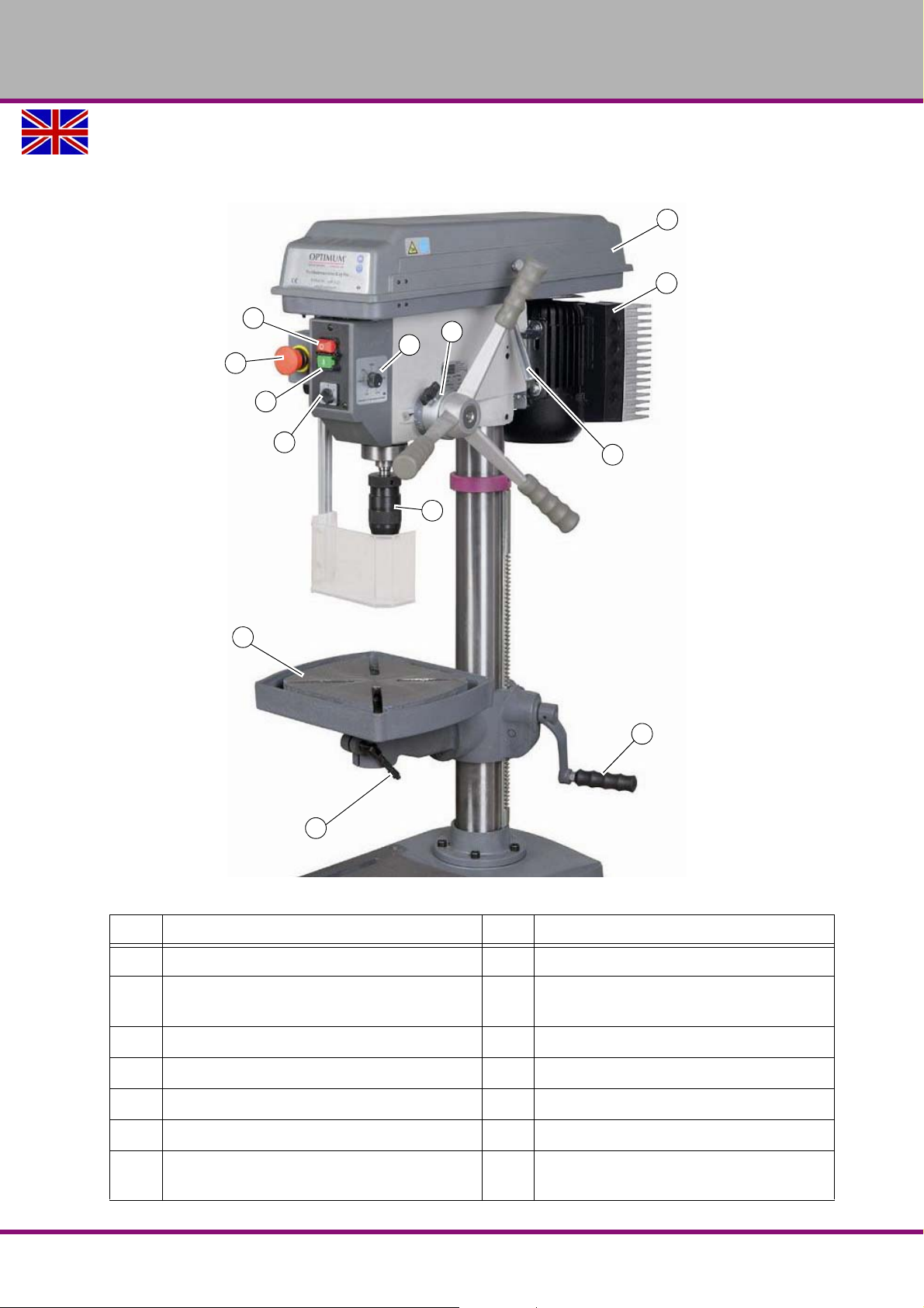
4 Operation
1
2
3
4
14
13
5
6
7
8
9
11
12
4.1 Control and indicating elements
OPTIMUM
MASCHINEN - GERMANY
Pos. Designation Pos. Designation
1
Push button "OFF“
EMERGENCY-STOP button
3
5
Clamping lever
7
Quick-action drill chuck
Img.4-1: B23Pro Vario
2
Push button "ON“
Switch for the turning direction
4
(only on 400V machines)
6
Scale of drill depth stop
8
Protective cover of V-belt housing
9
Handle for V-belt tension
11
Drilling table
Potentiometer for speed regulation
13
(only on Vario machines)
Operation
Version 2.0.2 2014-11-04 Page 31Original operating instructions
10
Lever for spindle sleeve feed
12
Table height adjustment
Frequency converter
14
(only on Vario machines)
B17Pro | B23Pro | B26Pro | B33Pro GB
Page 32
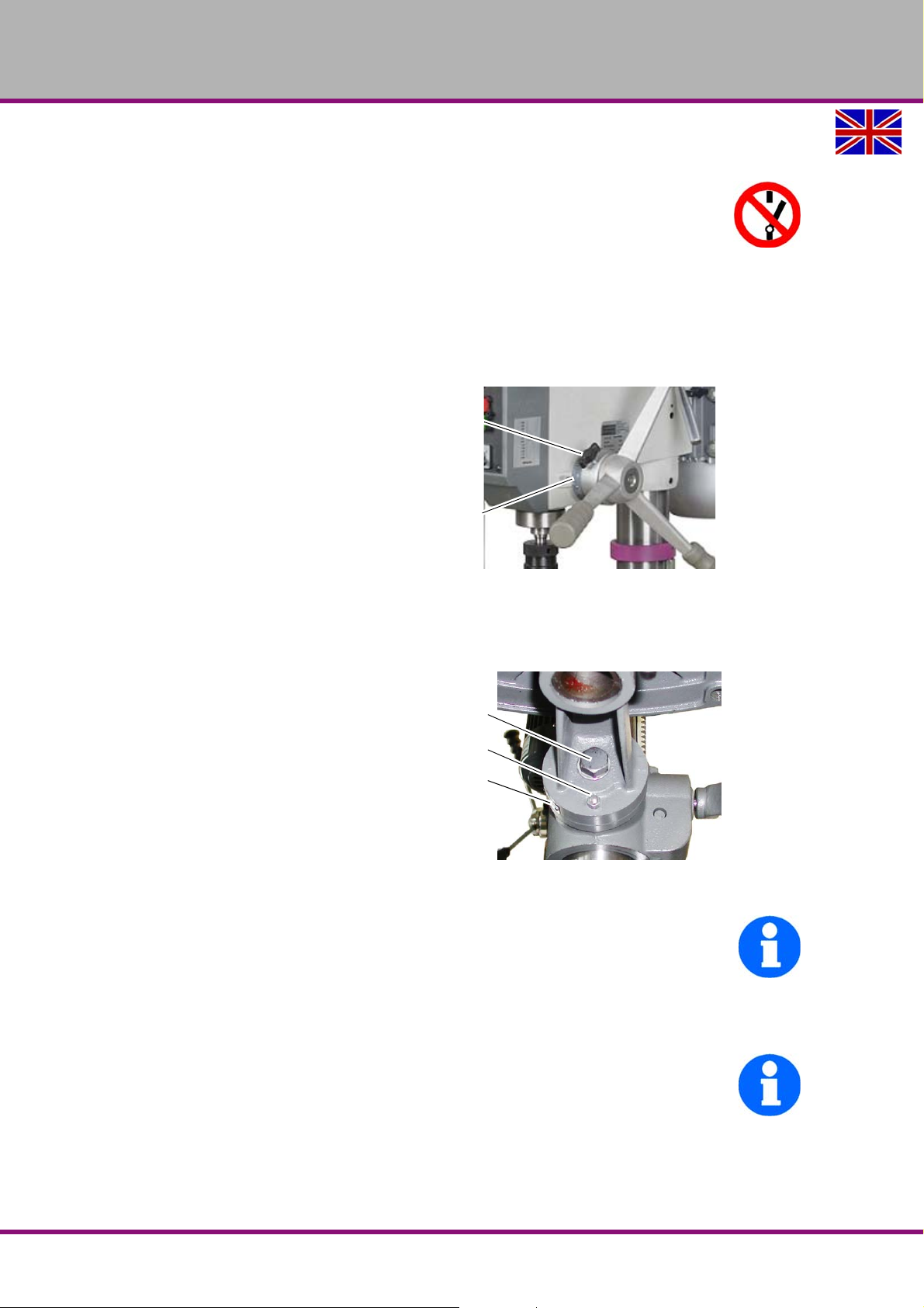
OPTIMUM
Locking screw
Drill depth stop
Scale
Fixing screw
Threaded pin
Scale
MASCHINEN - GERMANY
4.2 Safety
Use the drilling machine only under the following conditions:
The drilling machine is in proper working order.
The drilling machine is used as prescribed.
The operating manual is followed.
All safety devices are installed and activated.
All failures should be eliminated immediately. Stop the machine immediately in the event of any
abnormality in operation and make sure it cannot be started-up accidentally or without authorisation. Notify the person responsible immediatel y of any modification.
4.2.1 Drill depth stop
When drilling several holes of the same
depth you can use the drill depth stop.
Loosen the locking screw and turn the
graduated collar until the required drilling depth matches with the indicator.
Re-tighten the locking screw.
Img.4-2: Scale of drill depth stop
The spindle can now only be lowered to the set depth.
4.2.2 Inclination table
The drilling table can be inclined to the
right or to the left.
Loosen the fixing screw.
Pull out the threaded pin.
Img.4-3: Fixing screw
INFORMATION
If you can not pull out the threaded pin, so the seat can be solved by turning at the nut clockwise.
Set the desired angle using the scale.
Re-tighten the fixing screw again.
INFORMATION
The threaded pin is only provided for correct positioning of a horizontal level of the drilling table.
B17Pro | B23Pro | B26Pro | B33ProGB
Operation
Version 2.0.2 2014-11-04Page 32 Original operating instructions
Page 33
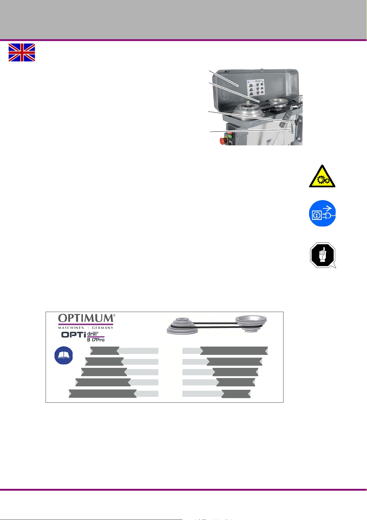
OPTIMUM
Protective cover
V-belt
Sliding rail screws
Handle
2520
1900
1400
900
500
8 x 825 mm (Li)
Item No. 030 0317 1108
Master Labels
MASCHINEN - GERMANY
4.3 Speed change
Set the required speed within the range of
15 to 225% using the potentiometer (only
on Vario machines). If the required speed
is not available, you must change the position of the V-belts.
Disconnect the machine from the elec-
trical supply.
Remove the screw fittings on the pro-
tective cover of the V-belts.
Img.4-4: Belt drive
Open the protective cover.
Loosen the sliding rail screws on the right and left side of the drill head and shift the motor
towards the quick-action drill chuck using the handle.
WARNING!
Do not open the cover hood until the drilling machine is disconnected from the electrical
supply.
Close and screw the cover hood after every speed change.
ATTENTION!
Watch for the proper tension of V-belts.
Too heavy or too low tension of the belt can cause damage.
The belts are correctly tensioned, when it can be by pressing with the fingers for about 1
cm.
4.3.1 Speed tables
B17Pro
Operation
Version 2.0.2 2014-11-04 Page 33Original operating instructions
B17Pro | B23Pro | B26Pro | B33Pro GB
Page 34
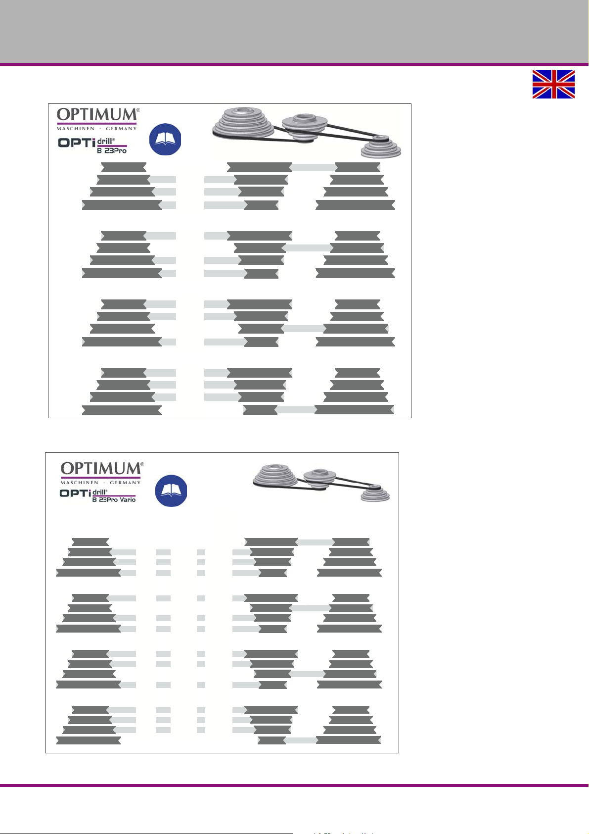
OPTIMUM
440
290
200
890
480
330
1040
1480
530
2440
1180
1770
V13 x 610 mm
Item No. 039V13610
V13 x 650 mm
Item No. 09V13650
Master Labels
Spindel
Spindle
mittlere Keilriemenscheibe
centre pulleys
Motor
~ 15 % 100 % ~ 225 %
440
890
200
330
290
480
1480
530
1040
2440
1180
1770
965
2200
450
735
695
1125
3480
1174
2520
4940
2880
4090
140
313
64
105
100
160
500
168
362
700
415
590
V13 x 610 mm
Item No. 039V13610
V13 x 650 mm
Item No. 09V13650
Master Labels
MASCHINEN - GERMANY
B23Pro
B23Pro Vario
B17Pro | B23Pro | B26Pro | B33ProGB
Operation
Version 2.0.2 2014-11-04Page 34 Original operating instructions
Page 35
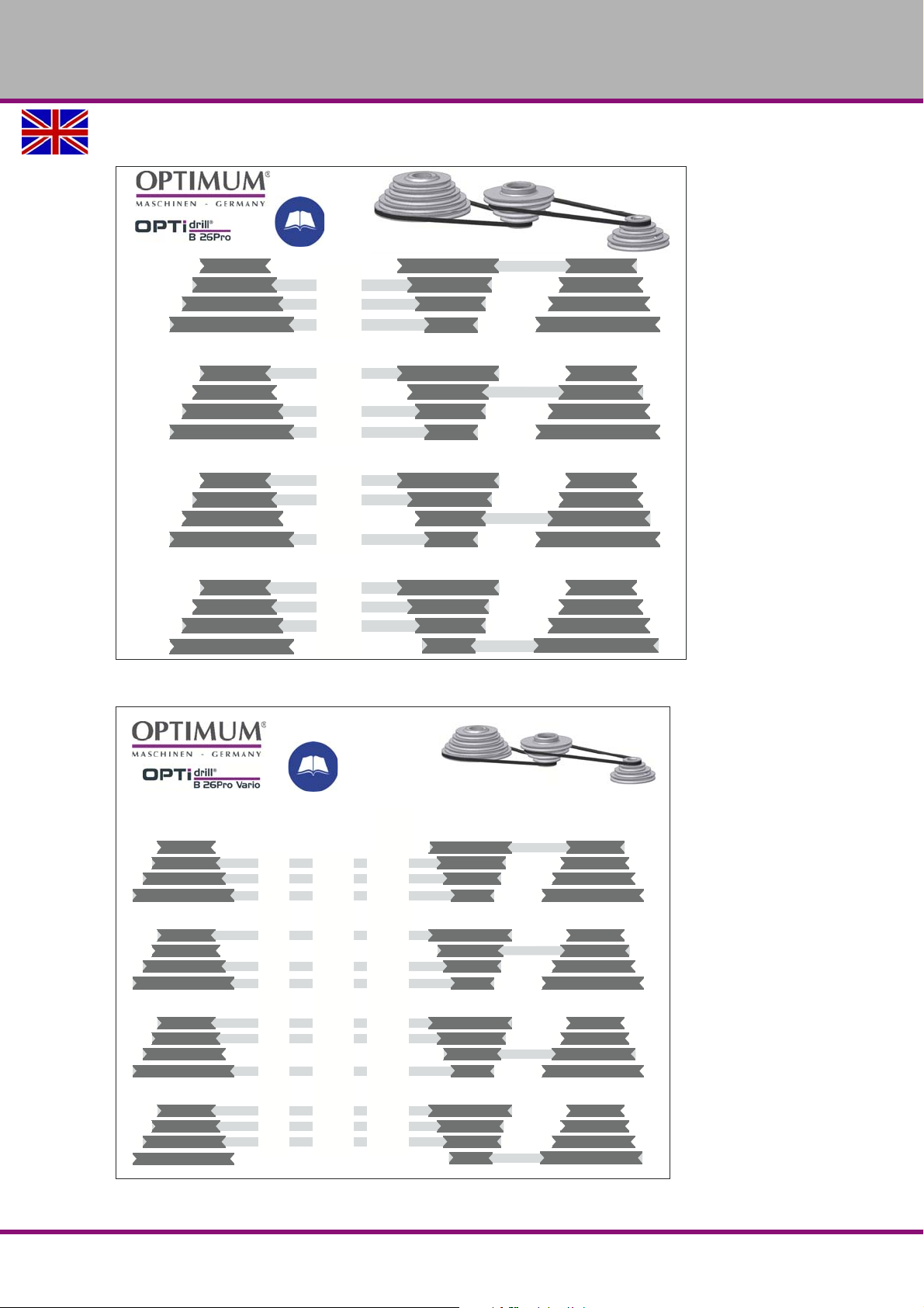
B26Pro
440
290
200
890
480
330
1040
1480
530
2440
1180
1770
Master Labels
V13 x 735 mm
Item No. 039V13735
V13 x 600 mm
Item No. 09V13600
Spindel
Spindle
mittlere Keilriemenscheibe
centre pulleys
Motor
~ 15 % 100 % ~ 225 %
440
890
200
330
290
480
1480
530
1040
2440
1180
1770
965
1450
450
735
695
1125
3000
1174
2520
4000
2150
3200
140
313
64
105
100
160
500
168
362
700
415
590
Master Labels
V13 x 735 mm
Item No. 039V13735
V13 x 600 mm
Item No. 09V13600
OPTIMUM
MASCHINEN - GERMANY
B26Pro Vario
Operation
Version 2.0.2 2014-11-04 Page 35Original operating instructions
B17Pro | B23Pro | B26Pro | B33Pro GB
Page 36
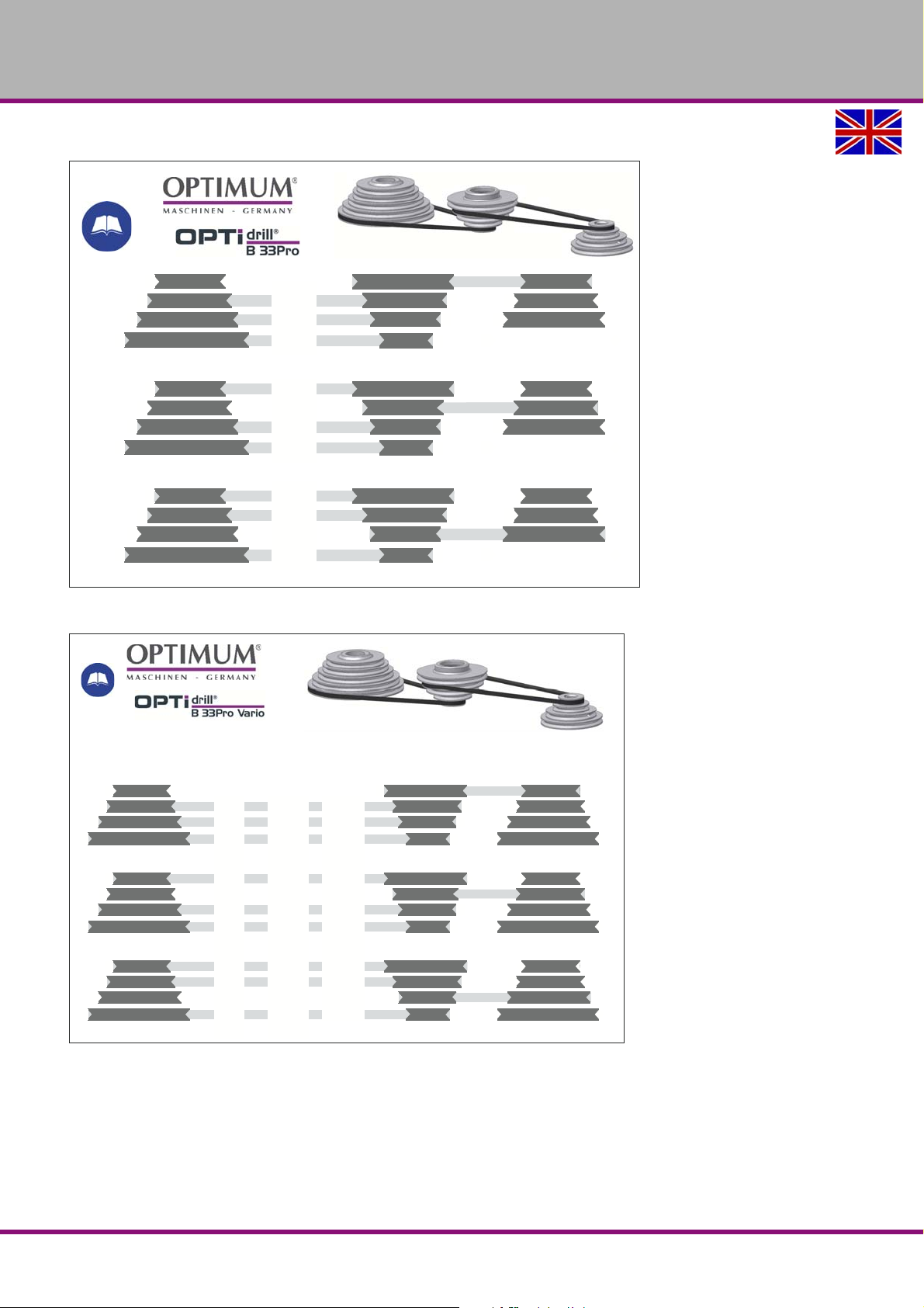
OPTIMUM
360
250
120
940
440
210
1260
1810
400
V13 x 735 mm
Item No. 039V13735
V13 x 860 mm
Item No. 0300333301
Master Labels
V13 x 735 mm
Item No. 039V13735
V13 x 860 mm
Item No. 0300333301
Spindel
Spindle
mittlere Keilriemenscheibe
centre pulleys
Motor
~ 15 % 100 % ~ 225 %
360
940
120
210
250
440
1810
400
1260
910
2150
300
520
600
1020
3850
930
2800
130
310
45
75
85
145
550
130
400
Master Labels
MASCHINEN - GERMANY
B33Pro
B33Pro Vario
B17Pro | B23Pro | B26Pro | B33ProGB
Operation
Version 2.0.2 2014-11-04Page 36 Original operating instructions
Page 37
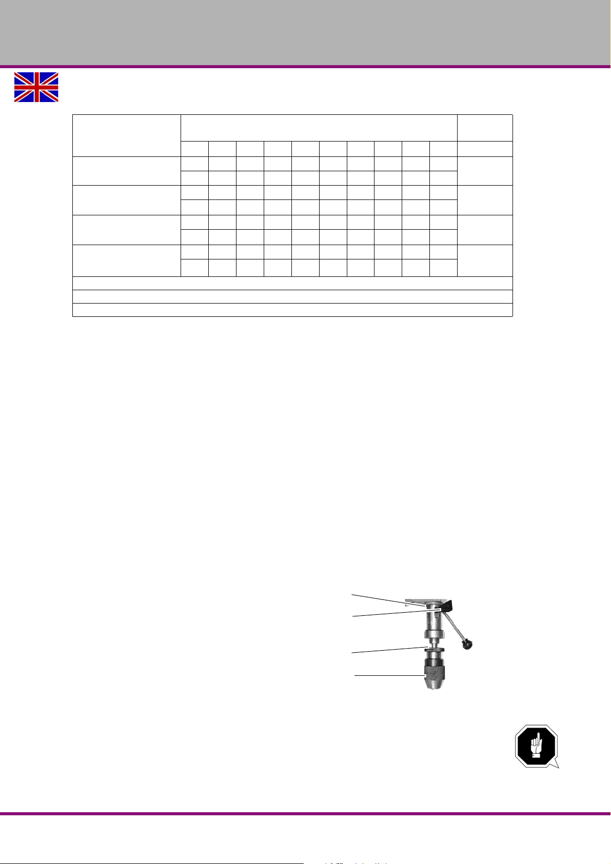
OPTIMUM
Drill sleeve
Drill drift
Upper part of quick-
action drill chuck
Lower part of quick-
action drill chuck
MASCHINEN - GERMANY
4.4 Standard values for speeds with HSS – Eco – twist drilling
Cooling
3)
E
E/oil
Oil
Oil
Material
Steel, unalloyed,
up to 600 N/mm
Structural steel, alloyed,
quenched and subsequently
drawn, up to 900N/mm2
Structural steel, alloyed,
quenched and subsequently
drawn, up to 1200 N/mm2
Stainless steels up to 900 N/
mm2
e.g. X5CrNi18 10
2
Cutter diameter
2345678910
n 1)5600 3550 2800 2240 2000 1600 1400 1250 1120
2)
f
0.04 0.063 0.08 0.10 0.125 0.125 0.16 0.16 0.20
n 3150 2000 1600 1250 1000 900 800 710 630
f 0.032 0.05 0.063 0.08 0.10 0.10 0.125 0.125 0.16
n 2500 1600 1250 1000 800 710 630 560 500
f" 0.032 0.04 0.05 0.063 0.08 0.10 0.10 0.125 0.125
n 2000 1250 1000 800 630 500 500 400 400
f 0.032 0.05 0.063 0.08 0.10 0.10 0.125 0.125 0.16
1): Speed [ n ] in r/min
2): Feed [ f ] in mm/r
3): Cooling: E = Emulsion; oil = cutting oil
The above mentioned indications are standard values. In some cases it may be advanta-
geous to increase or decrease these values.
When drilling a cooling or lubricating agent should be used.
For stainless materials (e.g. VA – or NIRO steel sheets) do not center as the material would
compact and the drill bit will become rapidly blunt.
The workpieces need to be tensed inflexibly and stably (vice, screw clamp).
4.5 Switching on the machine
The drilling machine is switched on in the following order.
Turn the change-over switch into the neutral position (0).
Push the green push-button, and wait two seconds.
Turn the change-over switch into the desired direction of rotation. The rotation of spindle
starts.
4.6 Switching off the machine
Push the red push-button, or turn the change over switch into the neutral position (0).
4.7 Quick-action drill chuck
The bench drilling machine is equipped
with a RÖHM quick-action drill chuck.
In order to clamp a drill bit, hold the upper
part of the quick-action drill chuck and turn
the lower part.
Img.4-5: Quick action - drill chuck
Operation
Version 2.0.2 2014-11-04 Page 37Original operating instructions
ATTENTION!
Make sure that the clamped tool is firmly and correctly fitted.
B17Pro | B23Pro | B26Pro | B33Pro GB
Page 38
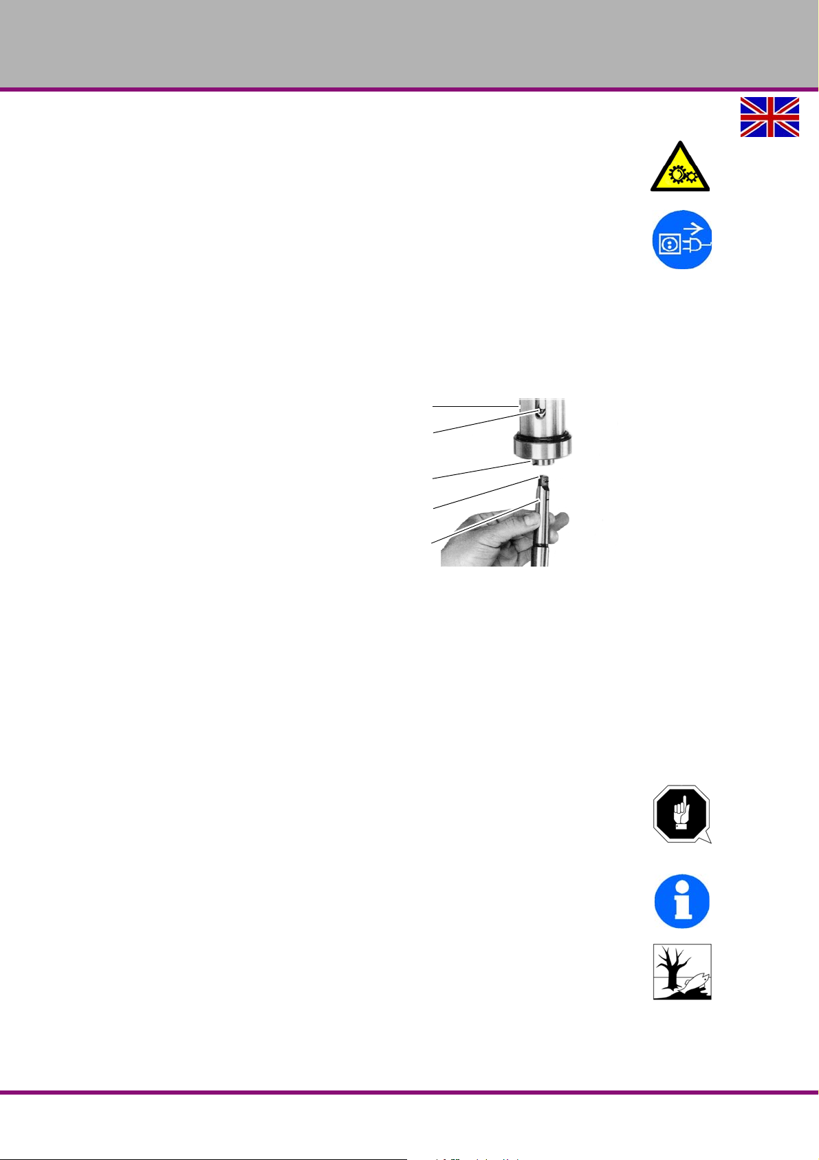
OPTIMUM
Drill sleeve
Opening for the
drill drift
Drilling spindle
driver
Taper mandrel
MASCHINEN - GERMANY
4.7.1 Disassembly quick- action drill chuck
The quick-action drill chuck and the taper mandrel are released from the drilling spindle with the
aid a drill drift.
WARNING!
Do not unfit the quick-action drill chuck until the drilling machine has been disconnected
from the power supply.
Disconnect the drilling machine from electrical power supply.
Move the drill sleeve down.
Turn the drilling spindle so that the opening at the drilling spindle sleeve coincides with the
opening at the drilling spindle.
Loosen the taper mandrel of the quick-action drill chuck with the help of a drill drift.
4.7.2 Assembly quick- action drill chuck
The quick-action drill chuck is secured
through a form-fit union (pulling heel)
against twisting in the drilling spindle.
A friction-locking union holds and centres
the quick-action drill chuck with the taper
mandrel in the drilling spindle.
Img.4-6: Taper mandrel
Check and, if necessary, clean the conical seat in the drilling spindle and at the taper man-
drel of the tool or the quick-action drill chuck.
Press the taper mandrel into the drilling spindle.
4.8 Cooling
The friction generated during rotation can cause the edge of the tool to become very hot.
The tool should be cooled during the drilling process. Cooling the tool with a suitable
cooling lubricant ensures better working results and a longer edge life of the tools. This is best
realised by a separate cooling equipment. If there is no cooling equipment included in the delivery volume, you can cool by means of a spray gun or a washing bottle.
ATTENTION!
Danger of injury due to brushes getting caught or pulled in. Use a spray gun or a
washing bottle for cooling.
INFORMATION
Use a water-soluble and non-pollutant drilling emulsion as a cooling agent.This can be acquired
from authorised distributors.
Make sure that the cooling agent is being collected.
Respect the environment when disposing of any lubricants and coolants.
Follow the manufacturer’s disposal instructions.
B17Pro | B23Pro | B26Pro | B33ProGB
Operation
Version 2.0.2 2014-11-04Page 38 Original operating instructions
Page 39
OPTIMUM
MASCHINEN - GERMANY
4.9 Before starting work
Before starting work, select the desired speed. It is depending on the used drilling diameter and
on the material.
"Speed change“ on page 33
WARNING!
For drilling jobs, it is necessary to clamp the workpiec e firmly to pr even t th e bit ca tch ing
on the pieces. A machine vice or clamping claws is a suitable clamping device.
Put a wooden or plastic board beneath the workpiece to avoid drilling through to the work table,
vice, etc.
If necessary, adjust the desired drilling depth with the drill depth stop to obtain a constant result.
When working with wood, make sure to use an adequate dust extraction unit, as sawdust can
constitute a health hazard. Wear a suitable dust mask when performing works at which dust is
generated.
4.10 During work
The spindle sleeve is advanced by means of the star wheel. Make sure that the feed is constant
and not too fast.
The spindle sleeve is returned to its initial position by the return spring.
WARNING!
Seizing of clothes and / or hair.
Make sure to wear well-fitting clothing during drilling work.
Do not use gloves.
If necessary, use a hairnet.
CAUTION!
Danger of bumps from the levers on the star wheel. Do not release the star wheel when
repositioning the drilling spindle sleeve.
The smaller the bit the more easily it may break. In the case of deep drilling, remove the bit
from time to time to remove filings from the drill. Add a few drops of oil to reduce friction and
prolong the service life of the bit.
CAUTION!
Danger of crushing. Do not place your hand between the drilling head and the spindle
sleeve.
Operation
Version 2.0.2 2014-11-04 Page 39Original operating instructions
B17Pro | B23Pro | B26Pro | B33Pro GB
Page 40
OPTIMUM
MASCHINEN - GERMANY
5 Determining the cutting speed and the speed
5.1 Table cutting speeds / infeed
Material t able
Recommended infeed f
Recommended
Material to be processed
Unalloyed construction steels
< 700 N/mm²
Alloyed construction steels
> 700 N/mm²
Alloyed steels
< 1000 N/mm²
Steels, low stability
< 800 N/mm²
Steel, high stability
> 800 N/mm²
non-rust steels
> 800 N/mm²
Cast iron
< 250 N/mm²
Cast iron
> 250 N/mm²
CuZn alloy
brittle
CuZn alloy
ductile
Aluminum alloy
up to 11% Si
Thermoplastics 20 - 40 0.05 0.10 0.20 0.30 0.40
Thermosetting materials with
organic filling
Thermosetting materials with
anorganic filling
cutting speed
Vc in m/min
2...3 >3...6 >6...12 >12...25 >25...50
30 - 35 0.05 0.10 0.15 0.25 0.35
20 - 25 0.04 0.08 0.10 0.15 0.20
20 - 25 0.04 0.08 0.10 0.15 0.20
40 0.05 0.10 0.15 0.25 0.35
20 0.04 0.08 0.10 0.15 0.20
12 0.03 0.06 0.08 0.12 0.18
15 - 25 0.10 0.20 0.30 0.40 0.60
10 - 20 0.05 0.15 0.25 0.35 0.55
60 - 100 0.10 0.15 0.30 0.40 0.60
35 - 60 0.05 0.10 0.25 0.35 0.55
30 - 50 0.10 0.20 0.30 0.40 0.60
15 - 35 0.05 0.10 0.20 0.30 0.40
15 - 25 0.05 0.10 0.20 0.30 0.40
in mm/revolution
Drill bit diameter d in mm
5.2 Speed table
Vc
in m/min
Drill bit
Ø
in mm
1,0 1274 1911 2548 3185 3822 4777 5732 6369 7962 9554
1,5 849 1274 1699 2123 2548 3185 3822 4246 5308 6369 7431 8493 10616 12739 16985 21231
2,0 637 955 1274 1592 1911 2389 2866 3185 3981 4777 5573 6369 7962 9554 12739 15924
2,5 510 764 1019 1274 1529 1911 2293 2548 3185 3822 4459 5096 6369 7643 10191 12739
3,0 425 637 849 1062 1274 1592 1911 2123 2654 3185 3715 4246 5308 6369 8493 10616
3,5 364 546 728 910 1092 1365 1638 1820 2275 2730 3185 3640 4550 5460 7279 9099
4,0 318 478 637 796 955 1194 1433 1592 1990 2389 2787 3185 3981 4777 6369 7962
Vc
in m/min
B50 GSMGB
4 6 8 10 12 15 18 20 25 30 35 40 50 60 80 100
Speed n in rpm
1114
12739 15924 19108 25478 31847
6
4 6 8 10 12 15 18 20 25 30 35 40 50 60 80 100
Determining the cutting speed and the speed
Version 2.0.2 dated 2014-11-04Page 40 Original operating instructions
Page 41

OPTIMUM
MASCHINEN - GERMANY
Drill bit
Ø
in mm
4,5 283 425 566 708 849 1062 1274 1415 1769 2123 2477 2831 3539 4246 5662 7077
5,0 255 382 510 637 764 955 1146 1274 1592 1911 2229 2548 3185 3822 5096 6369
5,5 232 347 463 579 695 869 1042 1158 1448 1737 2027 2316 2895 3474 4632 5790
6,0 212 318 425 531 637 796 955 1062 1327 1592 1858 2123 2654 3185 4246 5308
6,5 196 294 392 490 588 735 882 980 1225 1470 1715 1960 2450 2940 3920 4900
7,0 182 273 364 455 546 682 819 910 1137 1365 1592 1820 2275 2730 3640 4550
7,5 170 255 340 425 510 637 764 849 1062 1274 1486 1699 2123 2548 3397 4246
8,0 159 239 318 398 478 597 717 796 995 1194 1393 1592 1990 2389 3185 3981
8,5 150 225 300 375 450 562 674 749 937 1124 1311 1499 1873 2248 2997 3747
9,0 142 212 283 354 425 531 637 708 885 1062 1238 1415 1769 2123 2831 3539
9,5 134 201 268 335 402 503 603 670 838 1006 1173 1341 1676 2011 2682 3352
10,0 127 191 255 318 382 478 573 637 796 955 1115 1274 1592 1911 2548 3185
11,0 116 174 232 290 347 434 521 579 724 869 1013 1158 1448 1737 2316 2895
12,0 106 159 212 265 318 398 478 531 663 796 929 1062 1327 1592 2123 2654
13,0 98 147 196 245 294 367 441 490 612 735 857 980 1225 1470 1960 2450
14,0 91 136 182 227 273 341 409 455 569 682 796 910 1137 1365 1820 2275
15,0 85 127 170 212 255 318 382 425 531 637 743 849 1062 1274 1699 2123
16,0 80 119 159 199 239 299 358 398 498 597 697 796 995 1194 1592 1990
17,0 75 112 150 187 225 281 337 375 468 562 656 749 937 1124 1499 1873
18,0 71 106 142 177 212 265 318 354 442 531 619 708 885 1062 1415 1769
19,0 67 101 134 168 201 251 302 335 419 503 587 670 838 1006 1341 1676
20,0 64 96 127 159 191 239 287 318 398 478 557 637 796 955 1274 1592
21,0 61 91 121 152 182 227 273 303 379 455 531 607 758 910 1213 1517
22,0 58 87 116 145 174 217 261 290 362 434 507 579 724 869 1158 1448
23,0 55 83 111 138 166 208 249 277 346 415 485 554 692 831 1108 1385
24,0 53 80 106 133 159 199 239 265 332 398 464 531 663 796 1062 1327
25,0 51 76 102 127 153 191 229 255 318 382 446 510 637 764 1019 1274
26,0 49 73 98 122 147 184 220 245 306 367 429 490 612 735 980 1225
27,0 47 71 94 118 142 177 212 236 295 354 413 472 590 708 944 1180
28,0 45 68 91 114 136 171 205 227 284 341 398 455 569 682 910 1137
29,0 44 66 88 110 132 165 198 220 275 329 384 439 549 659 879 1098
30,0 42 64 85 106 127 159 191 212 265 318 372 425 531 637 849 1062
31,0 41 62 82 103 123 154 185 205 257 308 360 411 514 616 822 1027
32,0 40 60 80 100 119 149 179 199 249 299 348 398 498 597 796 995
33,0 39 58 77 97 116 145 174 193 241 290 338 386 483 579 772 965
34,0 37 56 75 94 112 141 169 187 234 281 328 375 468 562 749 937
35,0 36 55 73 91 109 136 164 182 227 273 318 364 455 546 728 910
36,0 35 53 71 88 106 133 159 177 221 265 310 354 442 531 708 885
37,0 34 52 69 86 103 129 155 172 215 258 301 344 430 516 689 861
38,0 34 50 67 84 101 126 151 168 210 251 293 335 419 503 670 838
Vc
in m/min
4 6 8 10 12 15 18 20 25 30 35 40 50 60 80 100
Speed n in rpm
Determining the cutting speed and the speed
Version 2.0.2 dated 2014-11-04 Page 41Original operating instructions
B50 GSM GB
Page 42
OPTIMUM
n
c
d
------------
40m
min 3 14 0 03m
---------------------------------------------------
425 rpm===
Chisel edge length 10% of the
drill bit - Ø
MASCHINEN - GERMANY
Drill bit
Ø
in mm
39,0 33 49 65 82 98 122 147 163 204 245 286 327 408 490 653 817
40,0 32 48 64 80 96 119 143 159 199 239 279 318 398 478 637 796
41,0 31 47 62 78 93 117 140 155 194 233 272 311 388 466 621 777
42,0 30 45 61 76 91 114 136 152 190 227 265 303 379 455 607 758
43,0 30 44 59 74 89 111 133 148 185 222 259 296 370 444 593 741
44,0 29 43 58 72 87 109 130 145 181 217 253 290 362 434 579 724
45,0 28 42 57 71 85 106 127 142 177 212 248 283 354 425 566 708
46,0 28 42 55 69 83 104 125 138 173 208 242 277 346 415 554 692
47,0 27 41 54 68 81 102 122 136 169 203 237 271 339 407 542 678
48,0 27 40 53 66 80 100 119 133 166 199 232 265 332 398 531 663
49,0 26 39 52 65 78 97 117 130 162 195 227 260 325 390 520 650
50,0 25 38 51 64 76 96 115 127 159 191 223 255 318 382 510 637
5.3 Examples to calculatory determine the required speed for your drilling machine
The necessary speed is depending on the diameter of the drill bit, on the material which is
being machined as well as on the cutting material of the drill bit.
Material which needs to be drilled: St37
Cutting material (drill bit): HSS spiral bit
Set point of the cutting speed [
Diameter [d] of your drill bit: 30 mm = 0,03 m [meters]
Selected infeed [f] according to the table: about 0.35 mm/rev
v
] according to the table: 40 meters per minute
c
Speed n in rpm
Speed
Set a speed on your drilling machine which is less than the determined speed.
INFORMATION
In order to facilitate the production of larger drill holes they need to be pre-drilled. This way, you
reduce the cutting forces and improve the guiding of the drill bit.
The pre-drilling diameter is depending on the length of the
chisel edge. The chisel edge does not cut, but it squeezes
the material. The chisel edge is positioned at an angle of
55° to the major cutting edge.
As a general rule of thumb it applies: The pre-drilling
diameter is depending on the length of the chisel edge.
Recommended working steps for a drilling diameter of 30 mm
Example:
1st working step: Pre-drilling with Ø 5 mm.
2nd working step: Pre-drilling with Ø 15 mm.
3rd working step: Drilling with Ø 30 mm.
B50 GSMGB
Determining the cutting speed and the speed
Version 2.0.2 dated 2014-11-04Page 42 Original operating instructions
Page 43
OPTIMUM
MASCHINEN - GERMANY
6 Maintenance
In this chapter you will find important information about
Inspection
Maintenance
Repair
of the drilling machine.
ATTENTION !
Properly performed regular maintenance is an essential prerequisite for
operational safety,
failure-free operation,
long durability of the drilling machine and
the quality of the products which you manufacture.
Installations and equipment from other manufacturers must also be in good order and condition.
6.1 Safety
WARNING!
The consequences of incorrect maintenance and repair work may include:
Very serious injury to personnel working on the drilling machine,
Damage to the drilling machine.
Only qualified staff should carry out maintenance and repair work on the drilling
machine.
6.1.1 Preparation
WARNING!
Only carry out work on the drilling machine if it has been disconnected from the mains
power supply.
"Disconnecting and securing the drilling machine“ on page 17
Attach a warning sign.
6.1.2 Restarting
Before restarting run a safety check.
"Safety check“ on page 15
WARNING!
Before activating the drilling machine, double check that this will not
no dangers generated for persons,
the drilling machine is not damaged.
Maintenance
Version 2.0.2 2014-11-04 Page 43Original operating instructions
B17Pro | B23Pro | B26Pro | B33Pro GB
Page 44
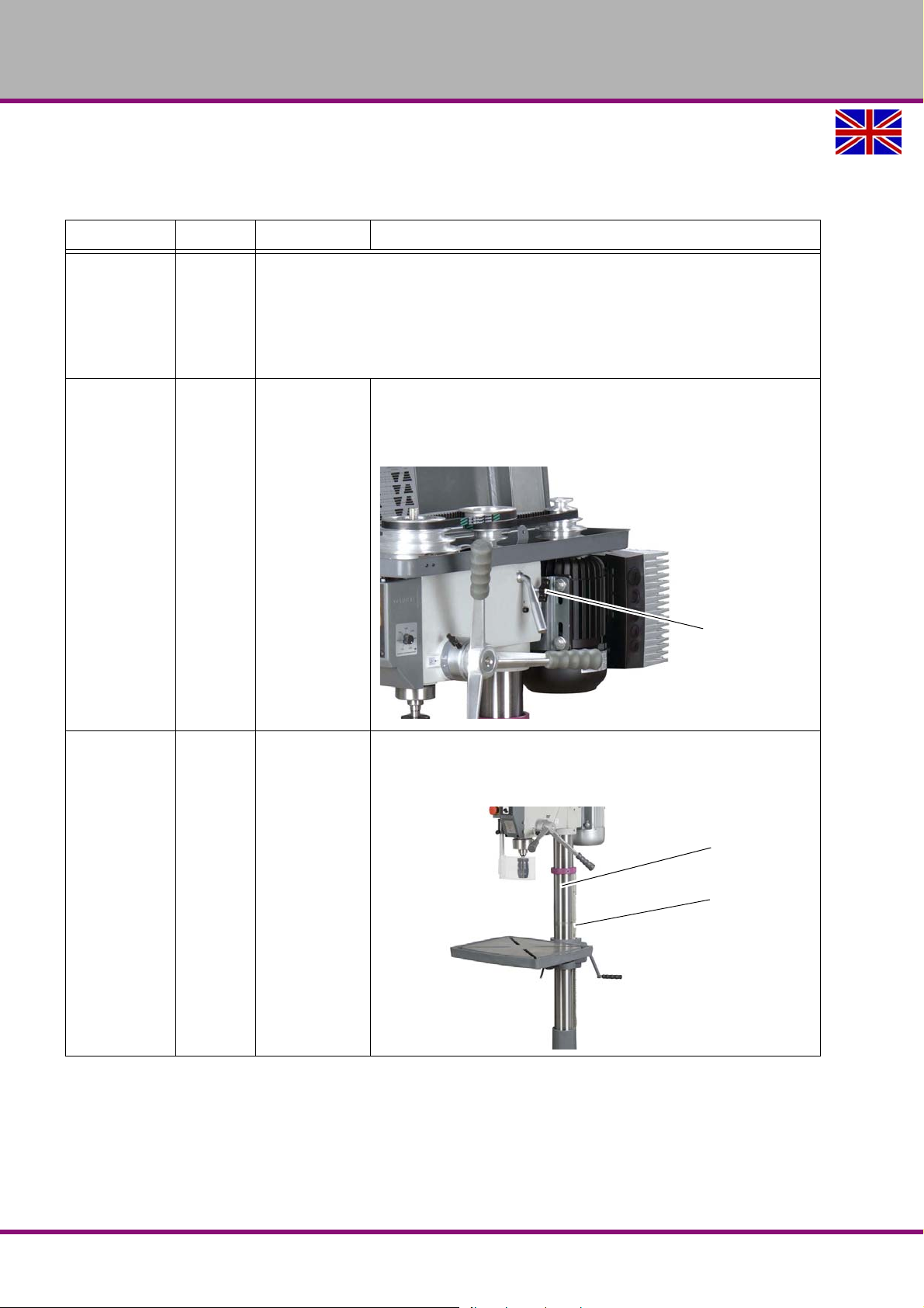
OPTIMUM
Slide rail screws
right-hand side
Drilling column
Toothed rack
MASCHINEN - GERMANY
6.2 Inspection and maintenance
The type and level of wear depends to a large extent on the individual usage and operating
conditions.
Interval Where? What? How?
Start of shift
after every
maintenance
or repair work
"Safety check“ on page 15
Drilling machine
Check if the slide rail screws for the V-belt tension on the
left and right side of the drilling head are well fastened.
Check if the V-belts are well tightened. Checking the ten-
sion of V-belts,
"Speed change“ on page 33.
every week
Every month
Loosening
Slide rail screws
Lubricate the drill column regularly with commercial oil.
Lubricate the rack regularly with commercial grease (e.g.
friction bearing grease).
lubricate
Rack and upright drill
B17Pro | B23Pro | B26Pro | B33ProGB
Version 2.0.2 2014-11-04Page 44 Original operating instructions
Maintenance
Page 45
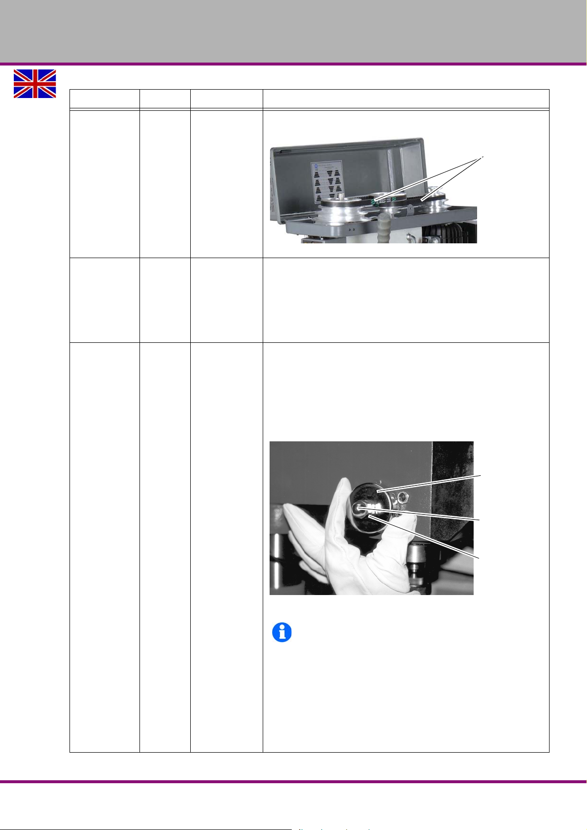
Interval Where? What? How?
V-belt
Spring housing
Capped nut
Nut
Check whether the V-belts have become porous and worn.
OPTIMUM
MASCHINEN - GERMANY
every six
months
every six
months
Visual inspection
V-belts at the drill head
Img.6-1: V-belt housing
Check the electrical equipment / parts of the drilling machine.
"Qualification of the staff“ on page 11
Testing
Electrical system
Loosen both nuts on the spring housing, approximately 1/4
counter-clockwise rotation. Under no circumstances must
the nuts be completely removed from the screw thread!
Hold the spring housing with one hand, while using the
other hand to slowly remove the housing.
Rotate the spring housing about its own axis until the pin
snaps into the next notch.
Drill depth stop
Spindle return
spring
Img.6-2: Spindle retur n spr i ng
INFORMATION
If the tension has increased, rotate the housing
clockwise and if the tension has decreased rotate
the housing counter-clockwise.
Ensure that the notch is always snapped into the
spring housing properly and subsequently tighten
the nut.
The second nut secures the first nut (capped nut).
When the nuts have been tightened they should not
touch the return spring housing.
as required
Maintenance
Version 2.0.2 2014-11-04 Page 45Original operating instructions
B17Pro | B23Pro | B26Pro | B33Pro GB
Page 46

OPTIMUM
MASCHINEN - GERMANY
6.3 Repair
6.3.1 Customer service technician
Request the assistance of an authorised customer service technician for any repair work. Contact your specialist dealer if you do not have customer service 's information or cont act Stürmer
Maschinen GmbH in Germany who can provide you with a specialist dealer's contact information. Optionally, the
Stürmer Maschinen GmbH
Dr.-Robert-Pfleger-Str. 26
D- 96103 Hallstadt
can provide a customer service technician, however, the request for a customer service techni-
cian can only be made via your specialist dealer.
If the repairs are carried out by qualified technical personnel, they must follow the indications
given in these operating instructions.
Optimum Maschinen Germany GmbH accepts no liability nor does it guarantee against damage
and operating malfunctions resulting from failure to observe these operating instructions.
For repairs only use
faultless and suitable tools
original parts or series components expressly authorized by Optimum Maschinen Germany
GmbH.
B17Pro | B23Pro | B26Pro | B33ProGB
Version 2.0.2 2014-11-04Page 46 Original operating instructions
Maintenance
Page 47
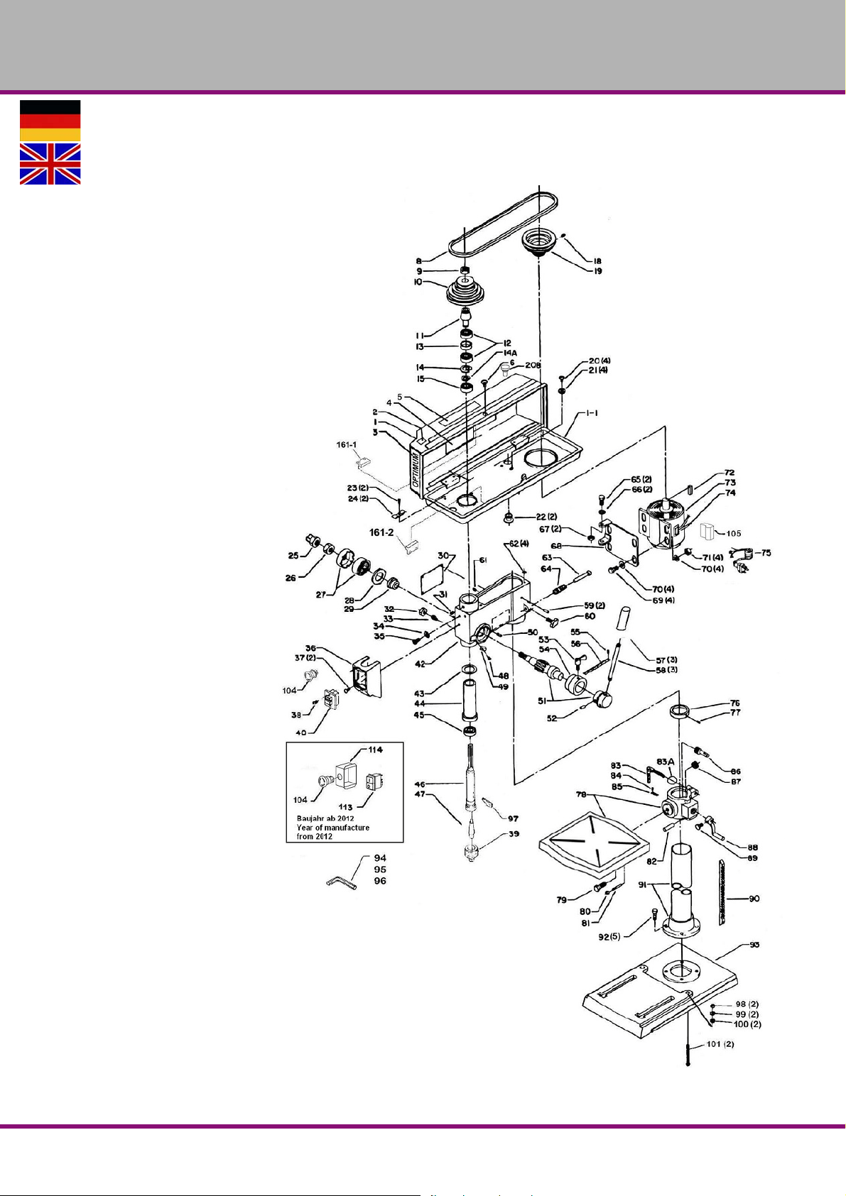
OPTIMUM
MASCHINEN - GERMANY
7 Ersatzteile - Spare parts - B17Pro, B23Pro, B26Pro, B33Pro - (Vario)
7.1 OPTI B17Pro
Abb.7-1: B17Pro
Ersatzteile - Spare parts - B17Pro, B23Pro, B26Pro, B33Pro - (Vario)
Version 2.0.2 2014-11-04 47Originalbetriebsanleitung
B17Pro | B23Pro | B26Pro | B33Pro DE | GB
Page 48
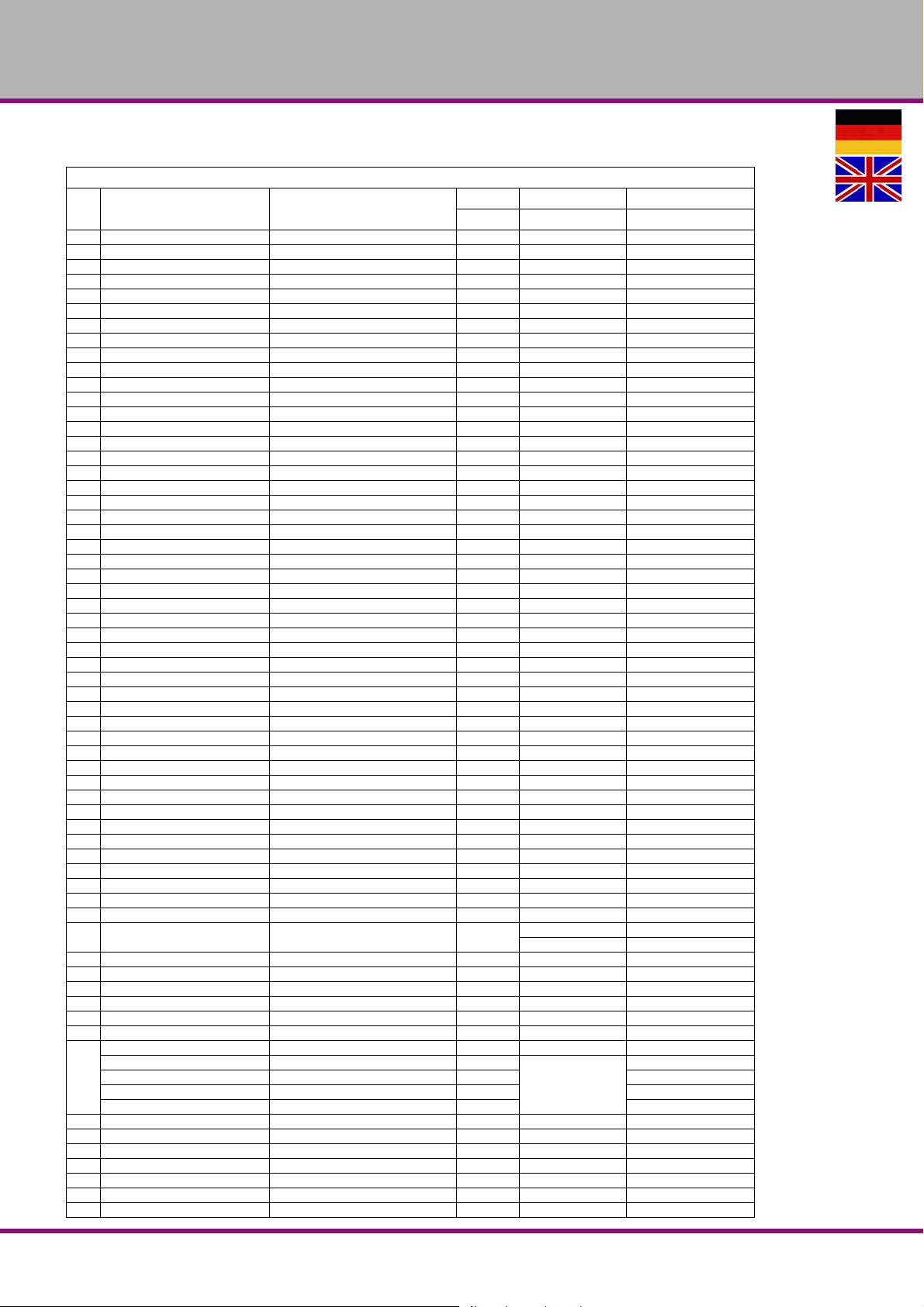
OPTIMUM
MASCHINEN - GERMANY
7.1.1 Bohrfutterschutz alter Typ - Drill chuck protection old type - B17Pro
7.1.2 Ersatzteilliste B17Pro
Bezeichnung Designation
Pos.
1 Deckel Cover 1 0300317101D
1-1 Unterteil Base part 1 0300317101U
2 CE-Label CE label 1 0300317102
3 Typenschild Name-plate 1 0300317103
4 Geschwindigkeitstabelle Table - speed 1 0300317104
5 Warnschild II Warning sign II 1 0300317105
6 Schraube M5 x 12 Screw 1 M5 x 12
8 Keilriemen V-belt 1 8 x 825 03003171108
9 Spindelmutter Spindle nut 1 0300317109
10 Riemenscheibe Spindel Spindle Pulley 1 0300317110
11 Mitnehmer Driving pin 1 0300317111
12 Kugellager Ball bearing 2 6203.2R 0406203.2R
13 Distanzscheibe Spacing screw 1 0300317113
14 Seegering Circlip 1 0300317114
15 Kugellager Ball bearing 1 6201.2RS 0406201.2R
18 Schraube Screw 1 M6 x 10
19 Riemenscheibe Motor Motor Pulley 1 0300317119
20 Schraube Screw 4 M6 x 12
21 Unterlegscheibe Washer 4 0300317121
22 Zugentlastung Strain relief 2 030031 7122
23 Schraube Screw 2 M6 x 10
24 Kabelschelle Cable clip 2 0300317124
25 Hutmutter Capped nut 1 1/2"-20 0300317125
26 Mutter Nut 1 1/2"-20 0300317126
27 Rückholfeder mit Gehäuse Turbination spring with cover 1 0300317127
28 Abdeckung Cover 1 0300317128
29 Rückholfedersitz Return spring seat 1 0300317129
30 Warnschild I Warning sign 1 0300317130
31 Schraube Screw 1 M8 x 8
32 Mutter Nut 1 M8
33 Schraube Screw 1 M8 x 18
34 Zahnscheibe Serrated disc 1 5x3 0300317134
35 Schraube Screw 1 M5 x 8
36 Schaltergehäuse Switch housing 1 0300317136
37 Schraube Screw 2 M5 x 12
38 Schraube Screw 1 M4,2x12
39 Bohrfutter Chuck 1 3050626
40 Schalter Switch 1 bis/to 2012 0300317140
42 Bohrkopf Boring head 1 0300317142
43 Gummiring Rubber ring 1 0300317143
44 Pinole Pinole 1 0300317144
45 Kugellager Ball bearing 1 6005.2RS 0406005.2R
46 Spindel Spindle 1 0300317146
47 Kegeldorn Taper mandril 1 Mk2B16 3050659
48 Schraube Screw 1 5mm 0300317148
49 Anzeige Display 1 0300317149
50 Stop-Stift Stop-pin 1 0300317150
51 Schaftritzel mit Nabe Shaft pinion with hub 1
52 Stift Pin 1 5x16 0300317152
53 Schraube Screw 1 M8 x 17 0300317153
54 Skalenring Dial 1 0300317154
55 Schraube Screw 1 5mm 0300317155
56 Skala Scale 1 0300317156-1
57 Griff Handle 3 old / old type 0300317157
58
59 Stift Pin 2 6 x 10 0300317159
60 Klemmschraube Clamping screw 1 M8 x 17 0300317153
61 Schraube Screw 1 M8 x 8
62 Gummiring Rubber ring 4 0300317162
63 Gleitstange Slide rod 1 0300317163
64 Feder Spring 1 0300317164
65 Schraube Screw 2 M8 x 30
Hebel Lever 3 alt / old type 0300317158
Aludruckgussgriff Aluminium casting lever 1
Passfeder Alugriff Key aluminum handle 1 03003171100
Schraube Alugriff Screw aluminium handle 1 0312367
Scheibe Alugriff Washer aluminium handle 1 0312368
Menge Grösse Artikelnummer
Qty. Size Item no.
alt / old type 0300317151
neu / new type 0300317151-1
03003171102
neu / new type
B17Pro | B23Pro | B26Pro | B33ProDE | GB
Ersatzteile - Spare parts - B17Pro, B23Pro, B26Pro, B33Pro - (Vario)
Version 2.0.2 2014-11-04 48 Originalbetriebsanleitung
Page 49
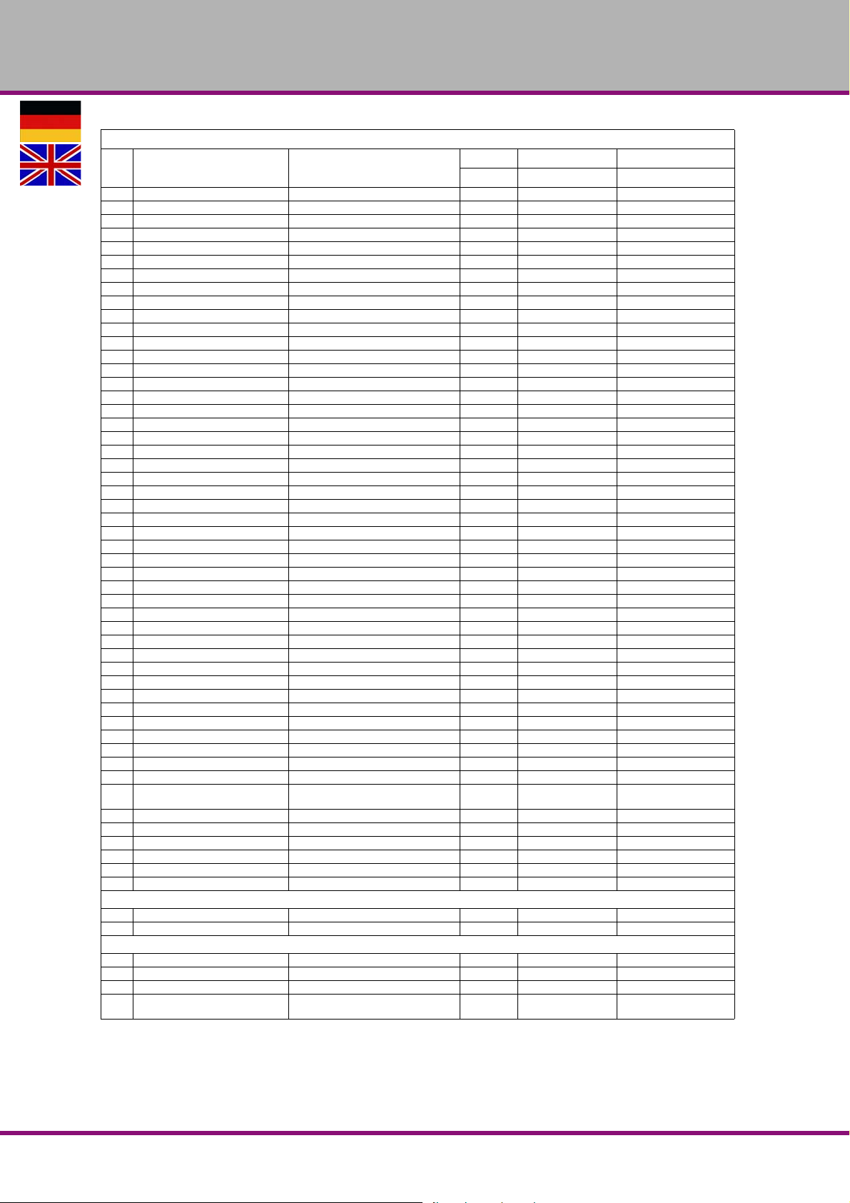
OPTIMUM
MASCHINEN - GERMANY
7.1.2 Ersatzteilliste B17Pro
Bezeichnung Designation
Pos.
66 Unterlegscheibe Washer 2 8 0300317166
67 Mutter Nut 2 M8
68 Motorhalteplatte Motor plate 1 0300317168
69 Schraube Screw 4 M8 x 30
70 Unterlegscheibe Washer 8 8 0300317170
71 Mutter Nut 4 M8
72 Paßfeder Key 1 0300317172
73 Motor Motor 1 0300317173
74 Motortypenschild Motor name-plate 1 0300317174
75 Kabel Cable 1 0300317175
76 Säulenring Column ring 1 0300317176
77 Schraube Screw 1 M6 x 10
78 Bohrtisch Drilling table 1 0300317178
78 Bohrtischhalter + Bohrtisch Support + Drilling table 1 0300317178-1
79 Schraube Screw 1 1/2"-12 0300317179
80 Mutter Nut 1 1/4"-20 0300317180
81 Kegelstift Taper pin 1 0300317181
82 Stift Pin 1 0300317182
83 Klemmhebel Clamping lever 1 0300317183
83A Unterlegscheibe Washer 1 10 0300317183A
84 Schraube Screw 1 0300317184
85 Skala für Neigung Scale for inclination 1 0300317185
86 Antriebsschnecke Worm drive 1 0300317186
87 Zahnrad Gear 1 0300317187
88 Kurbel Crank 1 ab 2004 0300317188-1
88 Kurbel Crank 1 vor 2004 0300317188
89 Schraube Screw 1 M6 x 10
90 Zahnstange Rack 1 0300317190
91 Säule Column 1 0300317191
92 Schraube Screw 5 M8 x 20
93 Maschinenfuss <5 Loch> Machine base 1 0300317193
93 Maschinenfuss <4 Loch> Machine base 1 03003171106
94 Inbusschlüssel Socket head wrench 1 3mm 0300317194
95 Inbusschlüssel Socket head wrench 1 4mm 0300317195
96 Inbusschlüssel Socket head wrench 1 6mm 0300317196
97 Austreiber Drill drift 0300317197
98 Mutter Nut 2 M8
99 Federring Lock washer 2 8 0300317199
100 Unterlegscheibe Washer 2 8 03003171100
101 Schraube Screw 2 M8 x 125
103 Säulenhalterung Column flange 1 03003171109
104 Not-Aus-Schalter Emergency Stop switch 1 03003171104
105 Klemmksaten Terminal box 1 03003171105
104 Not-Aus-Schalter Emergency Stop switch 1 0460058
113 Ein-Aus-Taster On-off button 1
114 Klemmkasten Terminal box 1 03003171114
161 Reed Kontakt Keilriemendeckel Reed contact belt cover 1 SQ2 (PS-3150) 0302024192
1S1 Schalter Switch 1 030031711S1
Mikroschalter Microswitch 1 SQ1-HY50 030031712018
Reed Kontakt Keilriemendeckel Reed contact belt cover 1 PS-3150 0302024192
Steuerplatine Control board 1 030031711A1
Teile ohne Abbildung - Parts without illustration
Pinole komplett Pinole complete 1 0300317144CPL
Bohrkopf mit Pinole komplett Drilling head with pinole - complete 1 03003171107
Komplett-Sätze - Complete sets
Kondensator Capacitor 1 12,5 µF 03003171101
Säule + Halterung Column + Column flange 1 03003171103
Motorklemmkasten Motor terminal box 1 03003171105
Bohrfutterschutz komplett mit
Schalter, alter Typ
Drill chuck guard complete with micro
switch, old type
Menge Grösse Artikelnummer
Qty. Size Item no.
ab /from 2012/230V/
KJD12
1 24V 03003171125
03003171113
Ersatzteile - Spare parts - B17Pro, B23Pro, B26Pro, B33Pro - (Vario)
Version 2.0.2 2014-11-04 49Originalbetriebsanleitung
B17Pro | B23Pro | B26Pro | B33Pro DE | GB
Page 50
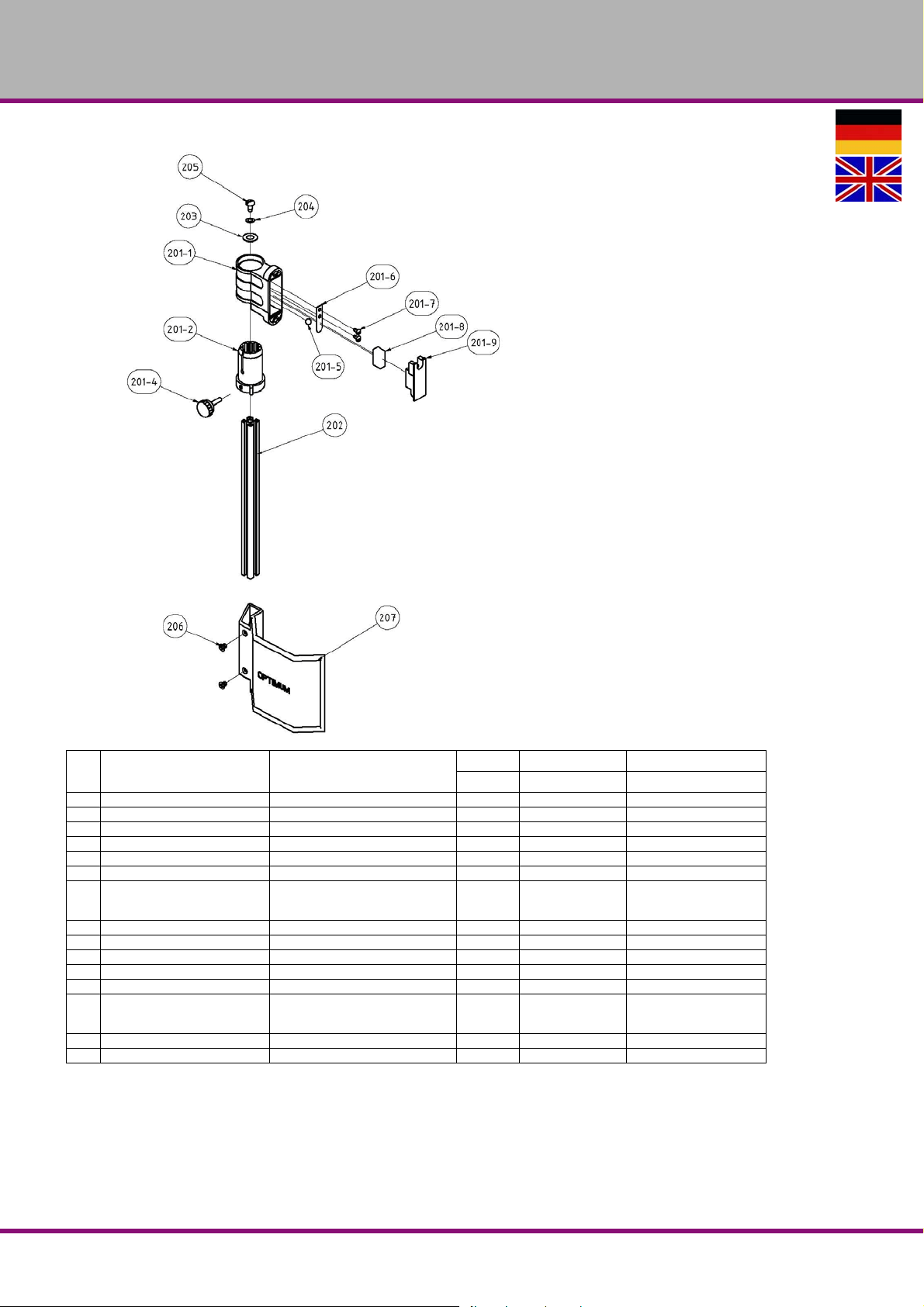
OPTIMUM
MASCHINEN - GERMANY
Bezeichnung Designation
Pos.
201 Halter Schutzeinrichtung komplett Support protection device complete 1 03003171201
201-1 Gehäuse Housing 1 030031712011
201-2 Aluminium Profilaufnahme Aluminium profile admission 1 030031712012
201-4 Klemmschraube Clamping screw 1 030031712014
201-5 Stahlkugel Steel ball 1 030031712015
201-6 Federblech Spring plate 1 030031712016
201-7 Flachkopfschraube Cheese head screw 2
201-8 Mikroschalter Microswitch 1 SQ1-HY50 030031712018
201-9 Deckel Cover 1 030031712019
202 Aluminiumprofil Aluminium profile 1 275mm 03003171202
203 Scheibe Washer 1 GB 955-87 - 10 03003171203
204 Scheibe Washer 1 GB 955-87 - 6 03003171204
205 Flachkopfschraube Cheese head screw 1
206 Senkschraube Countersunk screw 2 GB 819-85 - M6x8 03003171206
207 Schutz Protection 1 135mm 03003171207
Menge Grösse Artikelnummer
Qty. Size Item no.
ANSI/ASME
B18.6.5M - M4x0.7 x
8
ANSI/ASME
B18.6.5M - M6x1 x
13
030031712017
B17Pro | B23Pro | B26Pro | B33ProDE | GB
Ersatzteile - Spare parts - B17Pro, B23Pro, B26Pro, B33Pro - (Vario)
Version 2.0.2 2014-11-04 50 Originalbetriebsanleitung
Page 51
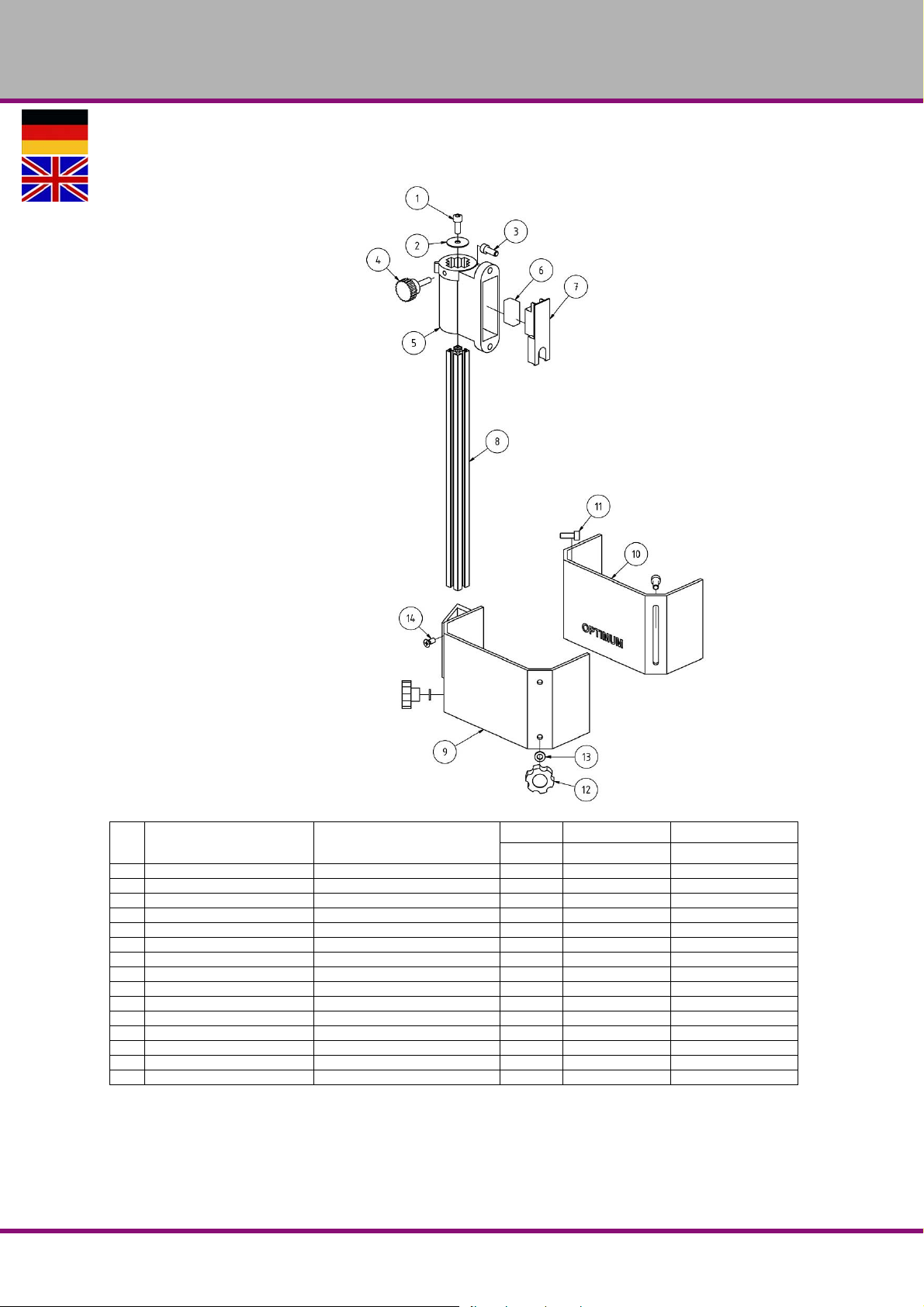
OPTIMUM
MASCHINEN - GERMANY
7.1.3 Bohrfutterschutz neuer Typ - Drill chuck protection new type - B17Pro
Bezeichnung Designation
Pos.
1 Innensechskantschraube Socket head screw 1 GB 70-85 - M6 x 10
2 Scheibe Washer 1 03020333123
3 Innensechskantschraube Socket head screw 2 GB 70-85 - M6 x 16
4 Rändelschraube Knurled screw 1 03020333125
5 Halterung Fixture 1 03020333126
6 Mikroschalter Microswitch 1 03020333127
7 Platte Plate 1 03020333128
8 Alu- Profil Aluminium profile 1 03003171202
9 Bohrfutterschutz A Drillig chuck safety A 1 03003171209
10 Bohrfutterschutz B Drillig chuck safety B 1 03003171210
11 Innensechskantschraube Socket head screw 2 GB 70-85 - M6 x 16
12 Rändelschraube Knurled screw 2 03003171212
13 Scheibe Washer 2 6 03003171213
14 Schraube Screw 2 M6x16
Halterung kpl. Holder cpl. 1 03008131201CPL
Ersatzteile - Spare parts - B17Pro, B23Pro, B26Pro, B33Pro - (Vario)
Version 2.0.2 2014-11-04 51Originalbetriebsanleitung
Menge Grösse Artikelnummer
Qty. Size Item no.
B17Pro | B23Pro | B26Pro | B33Pro DE | GB
Page 52
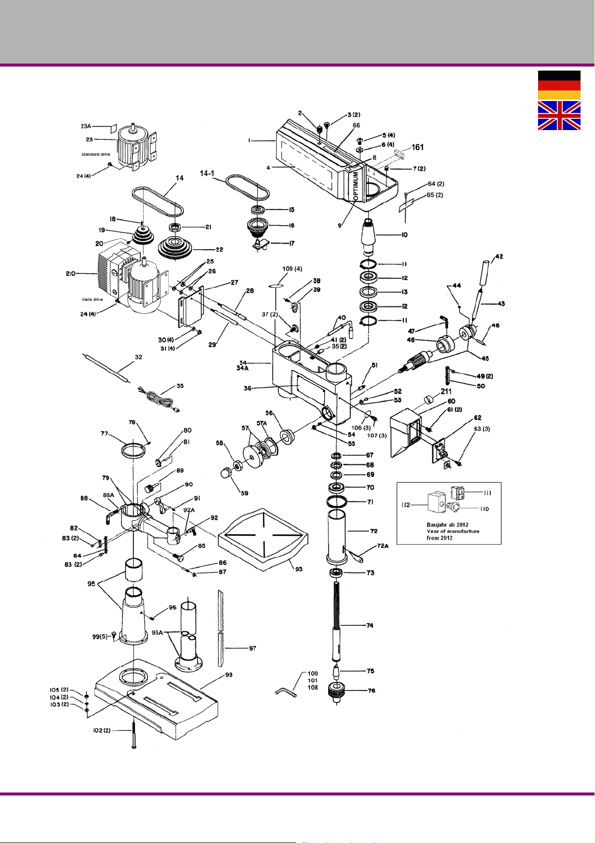
OPTIMUM
MASCHINEN - GERMANY
7.2 B23Pro, B23Pro Vario
Abb.7-2: B23Pro, B23Pro Vario
B17Pro | B23Pro | B26Pro | B33ProDE | GB
Ersatzteile - Spare parts - B17Pro, B23Pro, B26Pro, B33Pro - (Vario)
Version 2.0.2 2014-11-04 52 Originalbetriebsanleitung
Page 53
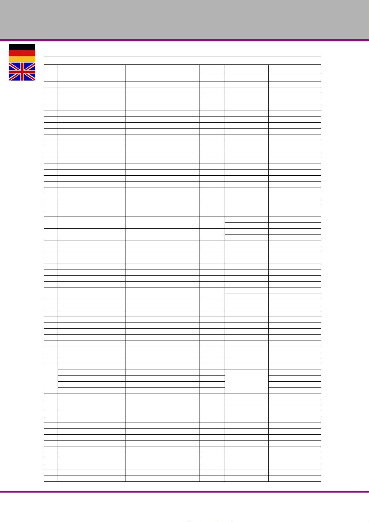
OPTIMUM
MASCHINEN - GERMANY
7.2.1 Ersatzteilliste B23Pro, B23Pro Vario
Bezeichnung Designation
Pos.
1 Riemengehäuse Pulley cover 1 0300323101
2 Schraube screw 1 0300323102
3 Schraube Screw 1 0300323103
4 Geschwindigkeitstabelle Table - speed 1 0300323104
5 Schraube Screw 4 M6 x 12
6 Unterlegscheibe Washer 4 6 0300323106
7 Schraube Screw 2 0300323107
8 CE Label CE label 1 0300323108
9 Typenschild Label 1 0300323109
10 Mitnehmer Driving pin 1 0300323110
11 Seegering Circlip 2 0300323111
12 Kugellager Ball bearing 2 6204.2R 0406204.2R
13 Ring Ring 1 0300323113
14 Keilriemen Motor V-belt motor 1 13 x 650 09V13650
14-1 Keilriemen Spindel V-belt spindle 1 13 x 610 039V13610
15 Kugellager Ball bearing 1 6202.2R 0406202.2R
16 Riemenscheibe Mitte Middle Pulley 1 0300323116
17 Zentriervorrichtung Centring device 1 0300323117
18 Paßfeder Key 1 0300323118
19 Riemenscheibe Motor Motor Pulley 1 0300323119
20 Schraube Screw 1 M8 x 12
21 Spindelmutter Spindle nut 1 0300323121
22 Riemenscheibe Spindel Spindle Pulley 1 0300323122
23 Motor Motor 1
23A Typschild Motor Motor name-plate 1
24 Schraube Screw 1 M8 x 30
25 Mutter Nut 4 M12
26 Unterlegscheibe Washer 2 12 0300323126
27 Motorplatte Motor plate 2 0300323127
28 Gleitstange rechts Sliding rod right 1 0300323128
29 Gleitstange links Sliding rod left 1 0300323129
30 Unterlegscheibe Washer 1 8 0300323130
31 Mutter Nut 4 M8
32 Kabel Motor Cable motor 1
33 Kabel Cable 1
34 Bohrkopf Head 1 0300323134
35 Stift Pin 1 0300323135
36 Warnschild I Warning sign 2 0300323136
37 Klemmschraube Clamping screw 1 0300323137
38 Schraube Screw 2 M8 x 16 0300323138
39 Exzenter Eccentric bolt 1 0300323139
40 Griff Riemenspannung Grip belt tension 1 0300323140
41 Schraube Screw 1 M10 x 12
42 Griff Handle 3 alt / old type 0300323142
43
44 Schraube Screw 3 0300323144
45 Schaftritzel mit Nabe Shaft pinion with hub 1
46 Spannstift Dowel pin 1 Ø 5x20 0300323146
47 Klemmschraube Clamping screw 1 M8 x 17 0300323147
48 Skalenring Scale ring 1 0300323148
49 Schraube Screw 1 5mm 0300323149
50 Skala Scale 2 0300326350
51 Stop-Stift Stop-pin 1 0300323151
52 Niete Rivet 1 5mm 0340116
53 Anzeiger Pointer 1 0300323153
54 Gewindestift Grub screw 1 M10x30 0340182
55 Mutter Nut 1 M10
56 Rückholfedersitz Spring seat 1 0300323156
57 Rückholfeder m. Abdeckung Turbination spring with cover 1 0300323157
Hebel Lever 3 alt / old type 0300323143
Aludruckgussgriff Aluminium casting lever 1
Passfeder Alugriff Key aluminum lever 1 03003231105
Schraube Alugriff Screw aluminium lever 1 03003231104
Scheibe Alugriff Washer aluminium lever 1 03003231103
Menge Grösse Artikelnummer
Qty. Size Item no.
230 V 0300323123
400 V 0300323323
230 V 0300323123A
400V 0300323323A
230 V 0300323132
400 V 0300323332
230 V 0300323133
400 V 0300323333
03003231102
neu / new type
alt / old type 0300323145
neu / new type 0300323145-1
Ersatzteile - Spare parts - B17Pro, B23Pro, B26Pro, B33Pro - (Vario)
Version 2.0.2 2014-11-04 53Originalbetriebsanleitung
B17Pro | B23Pro | B26Pro | B33Pro DE | GB
Page 54
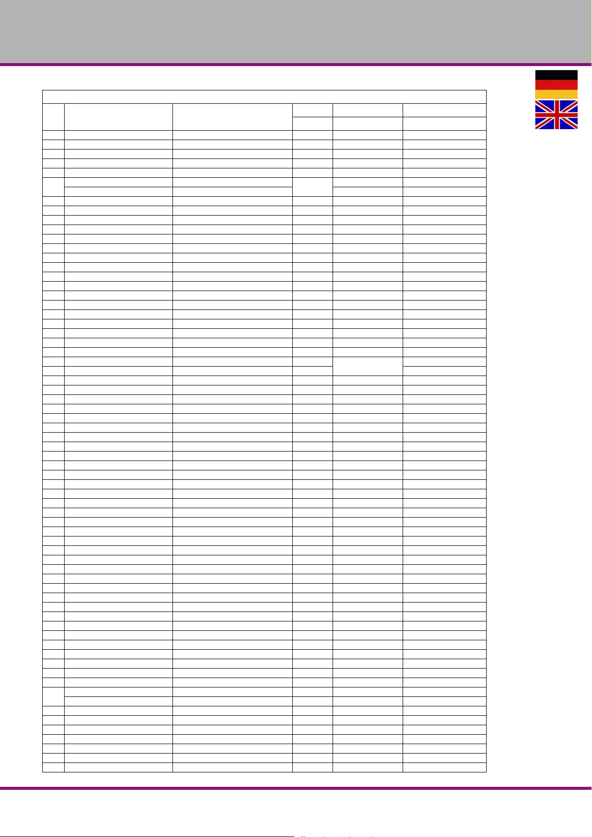
OPTIMUM
MASCHINEN - GERMANY
7.2.1 Ersatzteilliste B23Pro, B23Pro Vario
Bezeichnung Designation
Pos.
57A Ring Ring 1 0300323157A
58 Mutter Nut 1 0300323158
59 Hutmutter Capped nut 1 1/2"-20 0300323159
60 Schaltergehäuse Switch housing 1 0300323160
61 Schraube Screw 1 M5 x 16 0300323161
Schalter 230 V (ohne R/L) Switch 230 V (without R/L)
62
63 Schraube Screw 3 M4,2 x 12 0300323163
64 Schraube Screw 2 M5 x 8
65 Klammer Clamp 2 0300323165
66 Warnschild II Warning sign II 1 0300323166
67 Scheibe Washer 1 0300323167
68 Sicherungsblech Safety plate 1 0300323168
69 Zwischenring Ring 1 0300323169
70 Kugellager Ball bearing 1 6203.2R 0406203.2R
71 O-Ring O-ring 1 0300323171
72 Pinole Pinole 1 0300323172
72A Austreiber Drill drift 1 0300323172-1
73 Kugellager Ball bearing 1 6205.2R 0406205.2R
74 Spindel Spindle 1 0300323174
75 Kegeldorn Taper mandril 1 MK2 B16 3050659
76 Bohrfutter Drill chuck 1 3050626
77 Säulenring Column ring 1 0300323177
78 Schraube Screw 1 M6 x 8
79 Bohrtischträger Support 1 0300323179
79A Bohrtischträgerhalter Support holder 1 0300323179-2
80 Zahnrad Gear 1 0300333392
81 Zahnradwelle Gear axle 1 0300323181
82 0-Anzeige für Neigungsskala 0-display for scale of inclination 1 0313343
83 Schraube Screw 1 5mm 0300323183
84 Neigungsskala Scale of inclination 4 0300323184
85 Schraube Screw 1 5/8"-11 0300323185
86 Kegelstift Taper pin 1 0300323186
87 Mutter Nut 1 1/4"-20 0300323187
88 Klemmhebel Clamping lever 1 0300323188
88A Unterlegscheibe Washer 1 300323188A
89 Antriebsschnecke Worm drive 1 0300323189
90 Kurbel Crank 1 0300323190
91 Schraube Screw 1 M6 x 10
92 Klemmhebel Clamping lever 1 0321610
92A Unterlegscheibe Washer 1 0300323192A
93 Bohrtisch Drilling table 1 0300323193
95 Säule Column 0300323195
95A Säulenhalterung Column flange 0300323195-1
96 Schraube Screw 1 M10x12
97 Zahnstange Rack 1 0300323197
98 Maschinenfuss machine base 1 0300323198
99 Schraube Screw 5 M10x13
100 Inbusschlüssel Socket head wrench 1 3mm 03003231100
101 Inbusschlüssel Socket head wrench 1 5mm 03003231101
102 Schraube Screw 2 M8x125
103 Unterlegscheibe 8,4 Washer 8.4 2 8 03003231103
104 Federring Ø 8,4 Lock washer 2 8 03003231104
105 Mutter M8 Nut 2 M8
106 Zahn-Beilegscheibe Serrated disc - shim 3 5 03003231106
107 Schraube Screw 3 M5 x 8
108 Inbusschlüssel Socket head wrench 1 8mm 03003231108
109 Gummiring Rubber ring 4 1/4" 03003231109
110 Not-Aus-Schalter Emergency Stop switch 1 0460058
126
112 Klemmkasten Termin al box 1 03003171114
161 Reed Kontakt Keilriemendeckel Reed contact belt cover 1 PS-3150 0302024192
210 Motor mit Frequenzumrichter Motor with frequenci converter 1 400V 0313124
211 Potentiometer Potentiometer 1 0313199
Schalter 400 V (mit R/L) Switch 400 V (with R/L) 400 V 0300326362
Ein-Aus-Taster On-off button 1 230V 03003231126
Ein-Aus-Taster On-off button 1 400V 03003233126
Steuerplatine Control board 1 030032331A1
Schalter 230V Switch 230V 1 KJD18 230V 0300323162
Schaltereinheit 400V Switch unit 400V 1 KJD18 400V 0300323362
Menge Grösse Artikelnummer
Qty. Size Item no.
1
230 V 0300323162
B17Pro | B23Pro | B26Pro | B33ProDE | GB
Ersatzteile - Spare parts - B17Pro, B23Pro, B26Pro, B33Pro - (Vario)
Version 2.0.2 2014-11-04 54 Originalbetriebsanleitung
Page 55
7.2.1 Ersatzteilliste B23Pro, B23Pro Vario
Bezeichnung Designation
Pos.
Mikroschalter Microswitch 1 SQ1-HY50 030031712018
Komplett-Sätze - Complete sets
Pinole kplt. Pinole cpl. 1 0300323172CPL
Säule + Halterung Column complete 1 0300323195CPL
Riemenscheibe Mitte kpl. Middle pulley with centring device 1 0300323116-1
Bohrfutterschutz komplett mit
Schalter, alter Typ
Drill chuck guard complete with micro
switch, old type
OPTIMUM
MASCHINEN - GERMANY
Menge Grösse Artikelnummer
Qty. Size Item no.
1 24V 03003231104
Ersatzteile - Spare parts - B17Pro, B23Pro, B26Pro, B33Pro - (Vario)
Version 2.0.2 2014-11-04 55Originalbetriebsanleitung
B17Pro | B23Pro | B26Pro | B33Pro DE | GB
Page 56
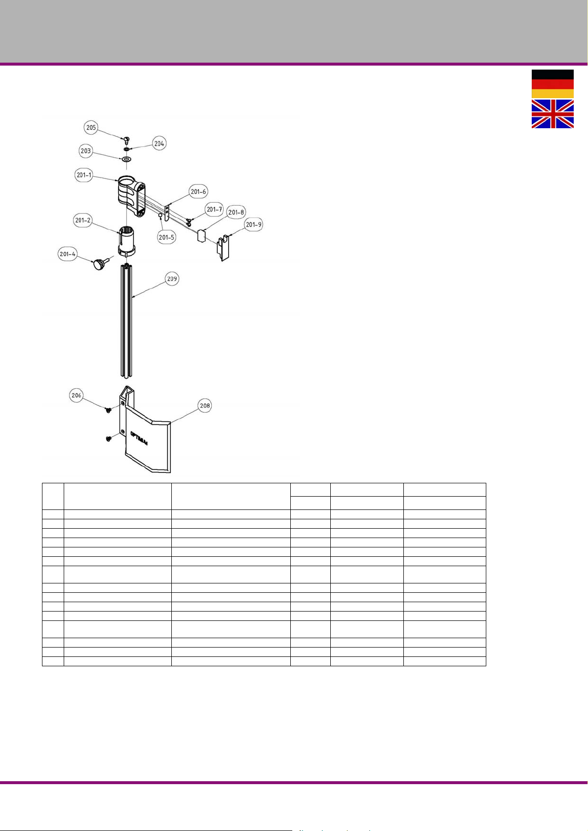
OPTIMUM
MASCHINEN - GERMANY
7.2.2 Bohrfutterschutz alter Typ - Drill chuck protection old type - B23Pro
Bezeichnung Designation
Pos.
201 Halter Schutzeinrichtung komplett Support protection device complete 1 03003171201
201-1 Gehäuse Housing 1 030031712011
201-2 Aluminium Profilaufnahme Aluminium profile admission 1 030031712012
201-4 Klemmschraube Clamping screw 1 030031712014
201-5 Stahlkugel Steel ball 1 030031712015
201-6 Federblech Spring plate 1 030031712016
201-7 Flachkopfschraube Cheese head screw 2
201-8 Mikroschalter Microswitch 1 030031712018
201-9 Deckel Cover 1 030031712019
203 Scheibe Washer 1 GB 955-87 - 10 03003171203
204 Scheibe Washer 1 GB 955-87 - 6 03003171204
205 Flachkopfschraube Cheese head screw 1
206 Senkschraube Countersunk screw 2 GB 819-85 - M6x8 03003171206
208 Schutz Protection 1 155mm 03011233208
209 Aluminiumprofil Aluminium profile 1 340mm 03011233209
Menge Grösse Artikelnummer
Qty. Size Item no.
ANSI/ASME B18.6.5M
- M4x0.7 x 8
ANSI/ASME B18.6.5M
- M6x1 x 13
030031712017
03003171205
B17Pro | B23Pro | B26Pro | B33ProDE | GB
Ersatzteile - Spare parts - B17Pro, B23Pro, B26Pro, B33Pro - (Vario)
Version 2.0.2 2014-11-04 56 Originalbetriebsanleitung
Page 57
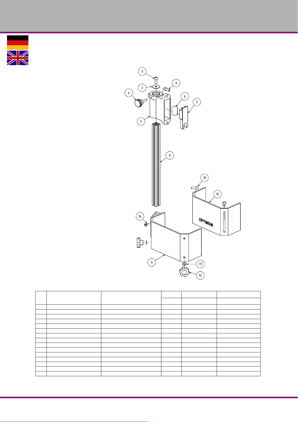
OPTIMUM
MASCHINEN - GERMANY
7.2.3 Bohrfutterschutz neuer Typ - Drill chuck protection new type - B23Pro
Bezeichnung Designation
Pos.
1 Innensechskantschraube Socket head screw 1 GB 70-85 - M6 x 10
2 Scheibe Washer 1 03020333123
3 Innensechskantschraube Socket head screw 2 GB 70-85 - M6 x 16
4 Rändelschraube Knurled screw 1 03020333125
5 Halterung Fixture 1 03020333126
6 Mikroschalter Microswitch 1 03020333127
7 Platte Plate 1 03020333128
8 Alu- Profil Aluminium profile 1 03003171202
9 Bohrfutterschutz A Drillig chuck safety A 1 03003171209
10 Bohrfutterschutz B Drillig chuck safety B 1 03003171210
11 Innensechskantschraube Socket head screw 2 GB 70-85 - M6 x 16
12 Rändelschraube Knurled screw 2 03003171212
13 Scheibe Washer 2 6 03003171213
14 Schraube Screw 2 M6x16
Halterung kpl. Holder cpl. 1 03008131201CPL
Ersatzteile - Spare parts - B17Pro, B23Pro, B26Pro, B33Pro - (Vario)
Version 2.0.2 2014-11-04 57Originalbetriebsanleitung
Menge Grösse Artikelnummer
Qty. Size Item no.
B17Pro | B23Pro | B26Pro | B33Pro DE | GB
Page 58
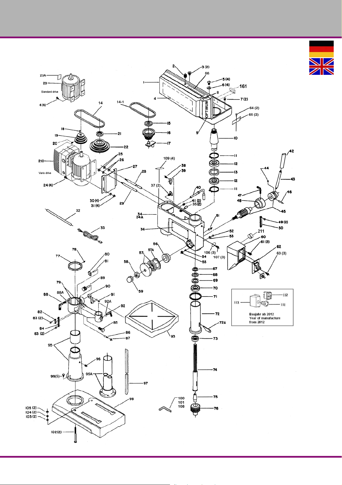
OPTIMUM
MASCHINEN - GERMANY
7.3 OPTI B26Pro, B26Pro Vario
Abb.7-3: OPTI B26 PRO
B17Pro | B23Pro | B26Pro | B33ProDE | GB
Ersatzteile - Spare parts - B17Pro, B23Pro, B26Pro, B33Pro - (Vario)
Version 2.0.2 2014-11-04 58 Originalbetriebsanleitung
Page 59
OPTIMUM
MASCHINEN - GERMANY
7.3.1 Ersatzteilliste B26Pro, B26Pro Vario
Pos.
Bezeichnung Designation
1 Riemengehäuse Pulley cover 1 0300326301
2 Schraube Screw 1 0300326302
3 Schraube Screw 1 0300323103
4 Geschwindigkeitstabelle Table - speed 1 0300326304
5 Schraube Screw 4 M6 x 12
6 Unterlegscheibe Washer 4 0300326306
7 Schraube Screw 2 0300326307
8 CE Label CE label 1 0300326308
9 Typenschild Label 1 0300326309
10 Mitnehmer Driving pin 1 0300326310
11 Seegering Circlip 2 0300326311
12 Kugellager Ball bearing 2 6205.2R 0406205.2R
13 Ring Ring 0300326313
14 Keilriemen Motor V-belt motor 1 13 x 600 09V13600
14-1 Keilriemen Spindel V-belt spindle 1 13 x 735 039V13735
15 Kugellager Ball bearing 1 6202.2R 0406202.2R
16 Riemenscheibe Mitte Middle Pulley 1 0300323116
17 Zentriervorrichtung Centring device 1 0300323117
18 Paßfeder Key 1 0300326318
19 Riemenscheibe Motor Motor Pulley 1 0300323119
20 Schraube Scre 1 M8x12
21 Spindelmutter Spindle nut 1 0300323121
22 Riemenscheibe Spindel Spindle Pulley 1 0300323122
23 Motor Motor
24 Schraube Screw 4 M8 x 30
25 Mutter Nut 2 M12
26 Unterlegscheibe Washer 2 12 0300326326
27 Motorplatte Motor plate 1 0300323162
28 Gleitstange rechts Sliding rod right 1 0300323128
29 Gleitstange links Sliding rod left 1 0300323129
30 Unterlegscheibe Washer 4 8 0300326330
31 Mutter Nut 4 M8
32 Kabel Motor Cable motor 1 0300326332
33 Kabel Cable 1 0300326333
34 Bohrkopf Boring head 1 0300326334
35 Stift Pin 2 0300326335
36 Warnschild I Warning sign 1 0300326336
37 Klemmschraube Clamping screw 2 0300323137
38 Schraube Screw 1 M8 x 16 0300323138
39 Exzenter Eccentric bolt 1 0300323139
40 Griff Riemenspannung Grip belt tension 1 0300326340
41 Schraube Screw 2 M10 x 12
42 Griff Handle 3 alt / old type 0300326342
43
44 Schraube Screw 1 0300326344
45
46 Spannstift Dowel pin 1 5 x 20 0300323146
47 Klemmschraube Clamping screw 1 M8 x 16 0300323147
48 Skalenring Scale ring 1 0300323148
49 Schraube Screw 1 5mm 0300326349
50 Skala Scale 1 0300326350
51 Stop-Stift Stop-pin 1 0300323151
52 Schraube Screw 2 5mm 0300326352
53 Anzeiger Pointer 1 0300326353
54 Schraube Screw 1 0300326354
55 Mutter Nut 1 M10
56 Rückholfedersitz Spring seat 1 0300323156
57 Rückholfeder mit Abdeckung Turbination spring with cover 1 0300323157
57a Ring Ring 1 0300326357
58 Mutter Nut 1 0300323158
59 Hutmutter Capped nut 1 1/2"-20 0300323159
60 Schaltergehäuse Switch housing 1 0300326360
Hebel Lever 3 alt / old type 0300323143
Aludruckgussgriff Aluminium casting lever 1
Passfeder Alugriff Key aluminum handle 1 0300323105
Schraube Alugriff Screw aluminium handle 1 0300323103
Scheibe Alugriff Washer aluminium handle 1 0300323104
Schaftritzel alt
Schaftritzel neu
Shaft pinion 1
Menge Grösse Artikelnummer
Qty. Size Item no.
1 230V 0300323123
1 400 V 0300323323
03003231102
neu / new type
alt
neu
0300326345
0300326345-1
Ersatzteile - Spare parts - B17Pro, B23Pro, B26Pro, B33Pro - (Vario)
Version 2.0.2 2014-11-04 59Originalbetriebsanleitung
B17Pro | B23Pro | B26Pro | B33Pro DE | GB
Page 60
OPTIMUM
MASCHINEN - GERMANY
7.3.1 Ersatzteilliste B26Pro, B26Pro Vario
Pos.
Bezeichnung Designation
61 Schraube M5x16 Screw M5x16 2 0300326361
62
63 Schraube Screw 3 M5 x 16 0300323163
64 Schraube Screw 2 M5 x 8
65 Klammer Clamp 2 0300326365
66 Warnschild II Warning sign II 2 0300326366
67 Spindelmutter Washer 1 0300326367
68 Sicherungsblech Safety plate 1 0300323168
69 Zwischenring Intermediate ring 1 0300326369
70 Kugellager Ball bearing 1 6203.2R 0406203.2R
71 O-Ring O-ring 1 0300326371
72 Pinole Pinole 1 0300326372
72a Austreiber Drill drift 1 0300326372-1
73 Kugellager Ball bearing 1 6206.2R 0406206.2R
74 Spindel Spindle 1 0300326374
75 Kegeldorn Taper mandril 1 MK3 B16 3050660
76 Bohrfutter Drill chuck 1 3050626
77 Säulenring Column ring 1 0300326377
78 Schraube Screw 1 M6x8
79 Bohrtischträger Support 1 0300326379
79a Bohrtischträgerhalter Support holder 1 0300326379-1
80 Zahnrad Gear 1 0300333392
81 Zahnradwelle Gear axle 1 0300323181
82 O-Anzeige für Neigungsskala O-display for scale of inclination 1 0313343
83 Schraube Screw 4 5mm 0300326383
84 Neigungsskala Scale of inclination 1 0300323184
85 Schraube Screw 1 5/8“-11 0300323185
86 Kegelstift Taper pin 1 0300323186
87 Mutter Nut 1 1/4"-20 0300326387
88 Klemmhebel Clamping lever 1 0300323188
88a Unterlegscheibe Washer 1 0300326388
89 Antriebsschnecke Worm driver 1 0300323189
90 Kurbel Crank 1 0300323190
91 Schraube Screw 1 0300326391
92 Klemmhebel Clamping lever 1 0300326392
92a Unterlegscheibe Washer 1 0300326392a
93 Bohrtisch Drilling table 1 0300326393
95 Säule Column 1 M10 x 12 0312603
95a Säulenhalterung Column flange 1 0300326395
96 Schraube Screw 1 M10 x 12
97 Zahnstange Rack 1 0300326397
98 Maschinenfuss Machine base 1 0300326398
99 Schraube Screw 5 M 10 x 30
100 Inbusschlüssel Socket head wrenc 1 3mm 03003263100
101 Inbusschlüssel Socket head wrench 1 5mm 03003263101
102 Schraube Screw 2 M8x125
103 Unterlegscheibe Washer 2 8 03003263103
104 Federring 8,4 Lock washer 2 8 03003263104
105 Mutter Nut 2 M8
106 Zahn-Beilegscheibe Serrated disc - shim 3 5 03003263106
107 Schraube Screw 3 M5 x 8
108 Inbusschlüssel Socket head wrench 1 8mm 03003263108
109 Gummiring Rubber ring 4 1/4“ 03003263109
110 Keilriemen V-belt 13x600 0391620
110 Not-Aus-Schalter Emergency Stop switch 1 0460058
111 Ein-Aus-Taster On-off button 1 400V 03003233126
112 Klemmkasten Terminal box 1 03003171114
161 Reed Kontakt Keilriemendeckel Reed contact belt cover 1 PS-3150 0302024192
210 Motor mit Frequenzumrichter Motor with frequenci converter 1 400V 0313124
211 Potentiometer Potentiometer 1 0313199
Schalter 230V (ohne R/L) Switch 230 V (without R/L)
Schalter 400V (mit R/L) Switch 400 V (with R/L) 400V 0300326362
Trafo 24V Transformer 24V 1 24V 03003171104
Relais Relais 1 KM-TV-5 03003171106
Schalter 230V Switch 230V 1 KJD18 230V 0300323162
Schaltereinheit 400V Switch unit 400V 1 KJD18 400V 0300323362
Mikroschalter Microswitch 1 SQ1-HY50 030031712018
Reed Kontakt Keilriemendeckel Reed contact belt cover 1 PS-3150 0302024192
Steuerplatine Control board 1 030032631A1
Menge Grösse Artikelnummer
Qty. Size Item no.
1
230V 0300323162
B17Pro | B23Pro | B26Pro | B33ProDE | GB
Ersatzteile - Spare parts - B17Pro, B23Pro, B26Pro, B33Pro - (Vario)
Version 2.0.2 2014-11-04 60 Originalbetriebsanleitung
Page 61
7.3.1 Ersatzteilliste B26Pro, B26Pro Vario
Bezeichnung Designation
Pos.
Teile ohne Abbildung - Parts without illustration
Motorlüfterdeckel Motor fan cover 03003231101
Komplett-Sätze - Complete sets
Pinole kpl. Spindle sleeve complete 0300326372CPL
Säule kpl. Column complete 0300326395CPL
Riemenscheibe Mitte kpl. Middle Pulley complete 0300323116-1
Werkzeugsatz in einer Box Tool box 03003231110
Bohrfutterschutz komplett mit
Schalter, alter Typ
Drill chuck guard complete with micro
switch, old type
OPTIMUM
MASCHINEN - GERMANY
Menge Grösse Artikelnummer
Qty. Size Item no.
1 24V 03003231104
Ersatzteile - Spare parts - B17Pro, B23Pro, B26Pro, B33Pro - (Vario)
Version 2.0.2 2014-11-04 61Originalbetriebsanleitung
B17Pro | B23Pro | B26Pro | B33Pro DE | GB
Page 62
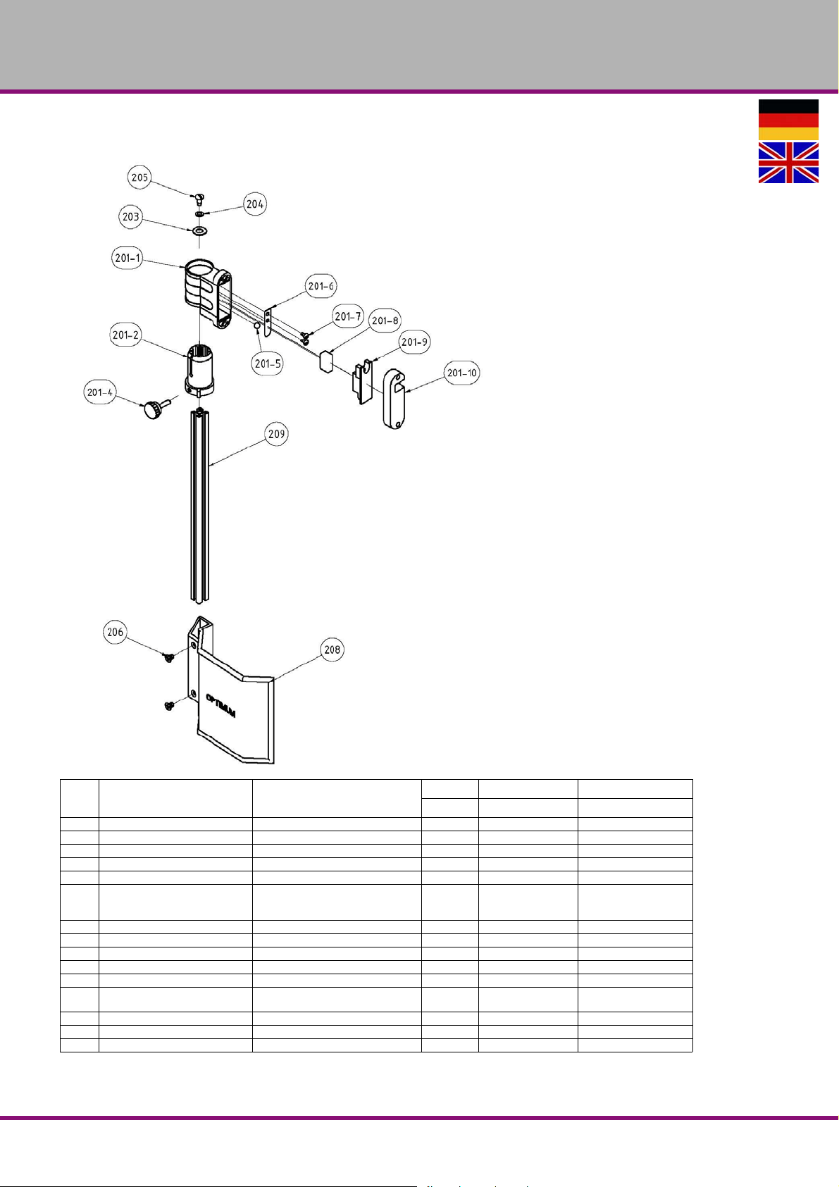
OPTIMUM
MASCHINEN - GERMANY
7.3.2 Bohrfutterschutz alter Typ - Drill chuck protection old type - B26Pro
Pos.
Bezeichnung Designation
201-1 Gehäuse Housing 1 030031712011
201-2 Aluminium Profilaufnahme Aluminium profile admission 1 030031712012
201-4 Klemmschraube Clamping screw 1 030031712014
201-5 Stahlkugel Steel ball 1 030031712015
201-6 Federblech Spring plate 1 030031712016
201-7 Flachkopfschraube Cheese head screw 2
201-8 Mikroschalter Microswitch 1 030031712018
201-9 Deckel Cover 1 030031712019
201-10 Abstandsplatte Distance plate 1 0300317120110
203 Scheibe Washer 1 GB 955-87 - 10 03003171203
204 Scheibe Washer 1 GB 955-87 - 6 03003171204
205 Flachkopfschraube Cheese head screw 1
206 Senkschraube Countersunk screw 2 GB 819-85 - M6x8 03003171206
208 Schutz Protection 1 155mm 03011233208
209 Aluminiumprofil Aluminium profile 1 340mm 03011233209
B17Pro | B23Pro | B26Pro | B33ProDE | GB
Ersatzteile - Spare parts - B17Pro, B23Pro, B26Pro, B33Pro - (Vario)
Menge Grösse Artikelnummer
Qty. Size Item no.
ANSI/ASME
B18.6.5M - M4x0.7 x 8030031712017
ANSI/ASME
B18.6.5M - M6x1 x 13
03003171205
Version 2.0.2 2014-11-04 62 Originalbetriebsanleitung
Page 63
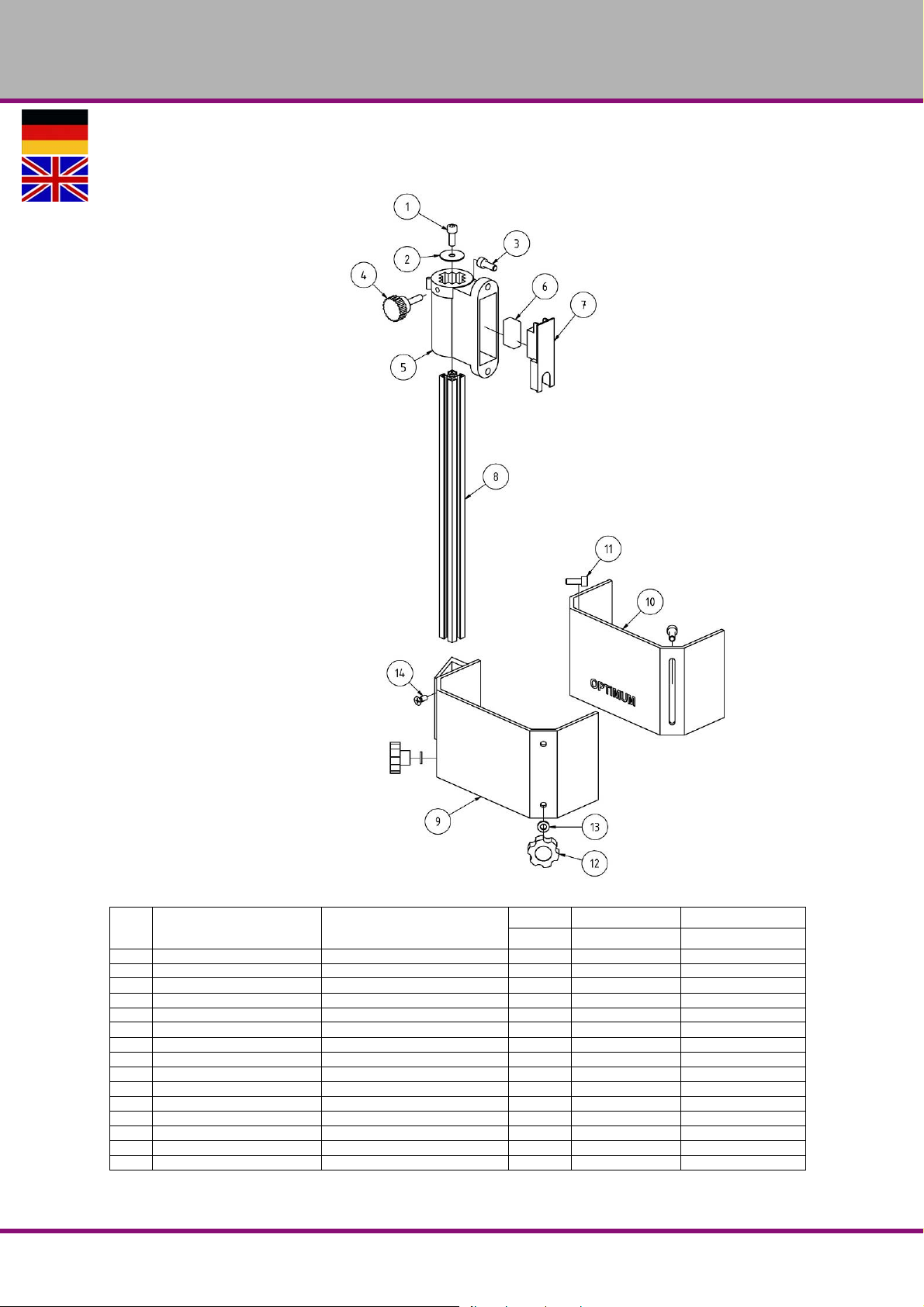
OPTIMUM
MASCHINEN - GERMANY
7.3.3 Bohrfutterschutz neuer Typ - Drill chuck protection new type - B26Pro
Pos.
Bezeichnung Designation
1 Innensechskantschraube Socket head screw 1 GB 70-85 - M6 x 10
2 S cheibe Washer 1 03020333123
3 Innensechskantschraube Socket head screw 2 GB 70-85 - M6 x 16
4 Rändelschraube Knurled screw 1 03020333125
5 Halterung Fixture 1 03020333126
6 Mikroschalter Microswitch 1 03020333127
7 Platte Plate 1 03020333128
8 Alu- Profil Aluminium profile 1 03003171202
9 Bohrfutterschutz A Drillig chuck safety A 1 03003171209
10 Bohrfutterschutz B Drillig chuck safety B 1 03003171210
11 Innensechskantschraube Socket head screw 2 GB 70-85 - M6 x 16
12 Rändelschraube Knurled screw 2 03003171212
13 Scheibe Washer 2 6 03003171213
14 Schraube Screw 2 M6x16
Halterung kpl. Holder cpl. 1 03008131201CPL
Ersatzteile - Spare parts - B17Pro, B23Pro, B26Pro, B33Pro - (Vario)
Version 2.0.2 2014-11-04 63Originalbetriebsanleitung
Menge Grösse Artikelnummer
Qty. Size Item no.
B17Pro | B23Pro | B26Pro | B33Pro DE | GB
Page 64
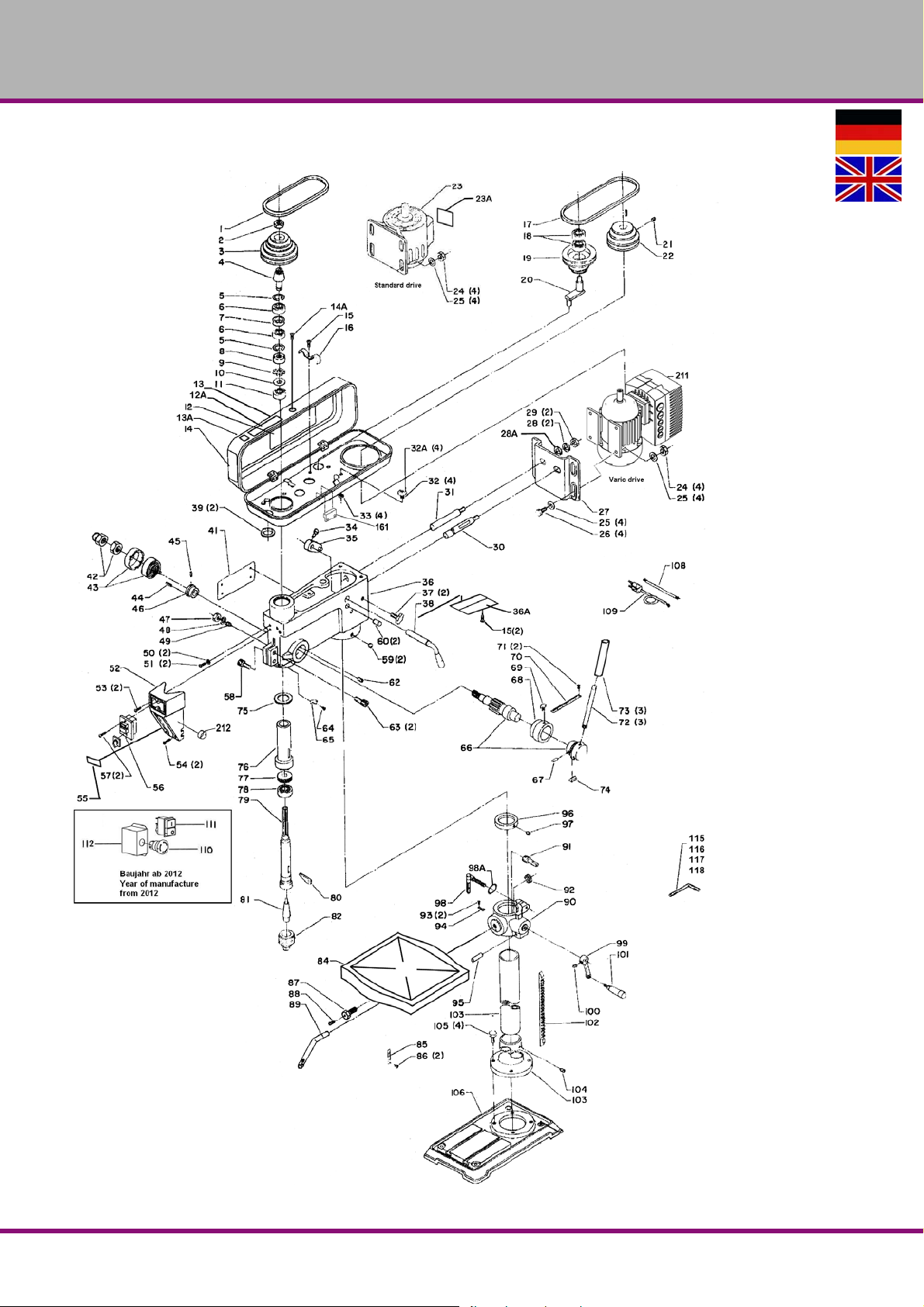
OPTIMUM
MASCHINEN - GERMANY
7.4 B33Pro, B33Pro Vario
Abb.7-4: B33Pro, B33Pro Vario
B17Pro | B23Pro | B26Pro | B33ProDE | GB
Ersatzteile - Spare parts - B17Pro, B23Pro, B26Pro, B33Pro - (Vario)
Version 2.0.2 2014-11-04 64 Originalbetriebsanleitung
Page 65
OPTIMUM
MASCHINEN - GERMANY
7.4.1 Ersatzteilliste B33Pro, B33Pro Vario
Pos.
Bezeichnung Designation
1 Keilriemen Spindel V-belt spindle 1 13 x 735 039V13735
2 Mutter Nut 1 0300333302
3 Riemenscheibe Spindel Spindle pulley 1 0300333303
4 Mitnehmer Driving pin 1 0300333304
5 Sicherungsring Safety ring 2 0300333305
6 Kugellager Ball bearing 2 6206-2R 0406206.2R
7 Distanzbuchse Bushing 1 0300333307
8 Mutter Nut 1 0300333308
9 Zahnscheibe Serrated disc 1 0300333309
10 Unterlegscheibe Washer 1 0300333340
11 Kugellager Ball bearing 1 6204.2R 0406204.2R
12 Geschwindigkeitstabelle Table - speed 1 0300333312
12 a Warnschild II Warning sign II 1 0300333312a
13 Riemengehäuse Pulley cover 1 0300333313
13 a CE Label CE label 1 0300333313
14 Typenschild Name-plate 1 0300333314
14 a Schraub Screw 1 M5x10
15 Schraube Screw 3 M 5x8
16 Kabelklemme Cable clamp 1 0300333316
17 Keilriemen Motor V-belt motor 1 13 x 860 0300333301
18 Kugellager Ball bearing 1 6202.2R 0406202.2R
19 Riemenscheibe Mitte Middle Pulley 1 0300333319
20 Zentrierstück Centring piece 1 0300333320
21 Schraube Screw 1 M 8x12
22 Riemenscheibe Motor Motor Pulley 1 0300333322
23
24 Mutter Nut 4 M 10
25 Beilegscheibe Washer 8 10 0300333325
26 Schraube Screw 4 M 10x30
27 Motorhalteplatte Motor plate 1 0300333327
28 Federring Lock washer 2 12 0300333328
28 a Unterlegscheibe Washer 2 12 0300333328a
29 Mutter Nut 2 M12
30 Gleitstange rechts Sliding rod right 1 0300333330
31 Gleitstange links Sliding rod left 1 0300333331
32 Schraube Screw 4 M6 x 16
32 a Unterlegscheibe Washer 4 6 0300333332a
33 Gummiring Rubber ring 4 0300333333
34 Schraube Screw 1 M8x16
35 Exzenter Eccentric bolt 1 0300333335
36 Bohrkopf Boring head 1 0300333336
36 a Schild Name-plate 1 0300333336
37 Klemmschraube Clamping screw 2 0300333337
38 Hebel Lever 1 0300333338
39 Ring Ring 2 0300333339
40 Niet Rivet 4 0300333340
41 Warnschild I Warning sign 1 0300333341
42a Mutter Nut 1 0300333342
42 Hutmutter Capped Nut 1 0300333342-1
43 Rückholfeder mit Gehäuse Return spring with housing 1 0300333343
44 Stift Pin 1 6x16 0300333344
45 Stift Pin 1 25 x 10 0300333345
46 Federsitz Spring seat 1 0300333346
47 Mutter Nut 1 M 10
48 Unterlegscheibe Washer 1 0300333348
49 Schraube Screw 1 M 10x27
50 Unterlegscheibe Washer 2 0300333350
51 Schraube Screw 2 M5x8
52 Schaltergehäuse Switch housing 1 0300333352
53 Schraube Screw 2 M6x16
54 Schraube Screw 2 M6x30
55 Geschwindigkeitstabelle Table - speed 1 0300333355
56 Schalter Switch 1 400V 0300326362
57 Schraube Screw 2 M5x12
58 Schraube Screw 1 M8x25
59 Schraube Screw 2 M10x12
60 Stift Pin 2 8x25 0300333360
Motor Motor 1 400V 0300333323
Menge Grösse Artikelnummer
Qty. Size Item no.
Ersatzteile - Spare parts - B17Pro, B23Pro, B26Pro, B33Pro - (Vario)
Version 2.0.2 2014-11-04 65Originalbetriebsanleitung
B17Pro | B23Pro | B26Pro | B33Pro DE | GB
Page 66
OPTIMUM
MASCHINEN - GERMANY
7.4.1 Ersatzteilliste B33Pro, B33Pro Vario
Pos.
Bezeichnung Designation
62 Stop-Stift Stop-pin 1 0300333362
63 Schraube Screw 2 M8x30
64 Schraube Screw 1 0300333364
65 Zeiger Pointer 1 0300333365
66 Schaftritzel Shaft pinion
67 Stift Pin 1 5x20 0300333367
68 Skalenring Scale ring 1 0300333368
69 Klemmschraube Clamping screw 1 0300333369
70 Bohrtiefenskala Scale - drilling depth 1 0300333370
71 Kerbstift Fluted pin 2 5mm 0300333371
72
73 Griff Handle 3 alt / old type 0300333373
74 Keil Key 1 0300333374
75 Gummiring Rubber ring 1 0300333375
76 Pinole Pinole 1 0300333376
77 Kugellager Ball bearing 1 04051208
78 Kugellager Ball bearing 1 6208.2R 0406208.2R
79 Spindel Spindle 1 0300333379
80 Austreiber Drill drift 1 0300333380
81 Kegeldorn Taper mandril 1 MK4 B16 3050661
82 Bohrfutter Drill chuck 1 3050626
84 Bohrtisch Drilling table 1 0300333384
85 Neigungsskala Scale of inclination 1 0300333385
86 Kerbstift Fluted pin 2 5mm 0300333386
87 Schraube Screw 1 0300333387
88 Bolzen Bolt 1 0300333388
89 Klemmhebel Clamping lever 1 0300333389
90 Bohrtischhalter Support 1 0300333390
91 Antriebsschnecke Worm drive 1 0300333391
92 Zahnrad Gear-wheel 1 0300333392
93 Schraube Screw 2 5mm 0313321
94 0-Skala 0-scale 1 03003333100
95 Stift Pin 1 0300333395
96 Säulenring Column ring 1 0300333396
97 Schraube Screw 1 M6x10
98 Klemmhebel Clamping lever 1 0300333398
98 a Unterlegscheibe Washer 1 12 0300333398
99 Kurbel Crank 1 0300333399
100 Schraube Screw 1 M 6x10
101 Griff Grip 1 03003333101
102 Zahnstange Rack 1 03003333102
103 Säule Column 1 03003333103
103 a Säulenhalterung Column flange 1 03003333103-1
104 Schraube Screw 1 03003333104
105 Schraube Screw 4 M 12x45 03003333105
105 Inbusschraube Socket head wrench 1 03003333105-1
106 Maschinenfuss Machine base 1 03003333106
108 Kabel Cable 1 03003333108
109 Kabel Cable 1 03003333109
115 Inbusschlüssel 3mm Socket head wrench 3mm 1 03003333115
116 Inbusschlüssel 4mm Socket head wrench 4mm 1 03003333116
117 Inbusschlüssel 5mm Socket head wrench 5mm 1 03003333117
118 Inbusschlüssel 6mm Socket head wrench 6mm 1 03003333118
119 Not-Aus-Schalter Emergency Stop switch 1 0460058
120 Ein-Aus-Taster On-off button 1 400V 03003233126
121 Klemmkasten Terminal box 1 03003171114
161 Reed Kontakt Keilriemendeckel Reed contact belt cover 1 PS-3150 0302024192
211 Motor mit Frequenzumrichter Motor with frequenci converter 1 400V 0313134
212 Potentiometer Potentiometer 1 0313199
Hebel Lever 3 alt / old type 0300333372
Aludruckgussgriff Aluminium casting lever 1
Passfeder Alugriff Key aluminum handle 1 03003231105
Schraube Alugriff Screw aluminium handle 1 03003231103
Scheibe Alugriff Washer aluminium handle 1 03003231104
Trafo 24V Transformer 24V 1 24V 03003171104
Relais Relais 1 KM-TV-5 03003171106
Schalter 230V Switch 230V 1 KJD18 230V 0300323162
Schaltereinheit 400V Switch unit 400V 1 KJD18 400V 0300323362
Menge Grösse Artikelnummer
Qty. Size Item no.
1 alt / old type 0300333366
1 neu / new type 0300333366-1
03003333104
neu / new type
B17Pro | B23Pro | B26Pro | B33ProDE | GB
Ersatzteile - Spare parts - B17Pro, B23Pro, B26Pro, B33Pro - (Vario)
Version 2.0.2 2014-11-04 66 Originalbetriebsanleitung
Page 67
7.4.1 Ersatzteilliste B33Pro, B33Pro Vario
Bezeichnung Designation
Pos.
Mikroschalter Microswitch 1 SQ1-HY50 030031712018
Reed Kontakt Keilriemendeckel Reed contact belt cover 1 PS-3150 0302024192
Steuerplatine Control board 1 030033331A1
Teile ohne Abbildung - Parts without illustration
Motorlüfterdeckel Motor fan cover 1
Klemmkasten Motor connection box 1 03003333107
Bohrfutterschutz alter Typ Drill chuck guard old type 1 3003335
Komplett-Sätze - Complete sets
Pinole kpl. Pinole complete 0300333376CPL
Säule kpl. Column complete 03003333103CPL
Werkzeugsatz in einer Box Tool box 0313350
Bohrfutterschutz mit Schalter
komplett
Drill chuck guard with micro switch
complete
OPTIMUM
MASCHINEN - GERMANY
Menge Grösse Artikelnummer
Qty. Size Item no.
1 24V 03003333125
Ersatzteile - Spare parts - B17Pro, B23Pro, B26Pro, B33Pro - (Vario)
Version 2.0.2 2014-11-04 67Originalbetriebsanleitung
B17Pro | B23Pro | B26Pro | B33Pro DE | GB
Page 68
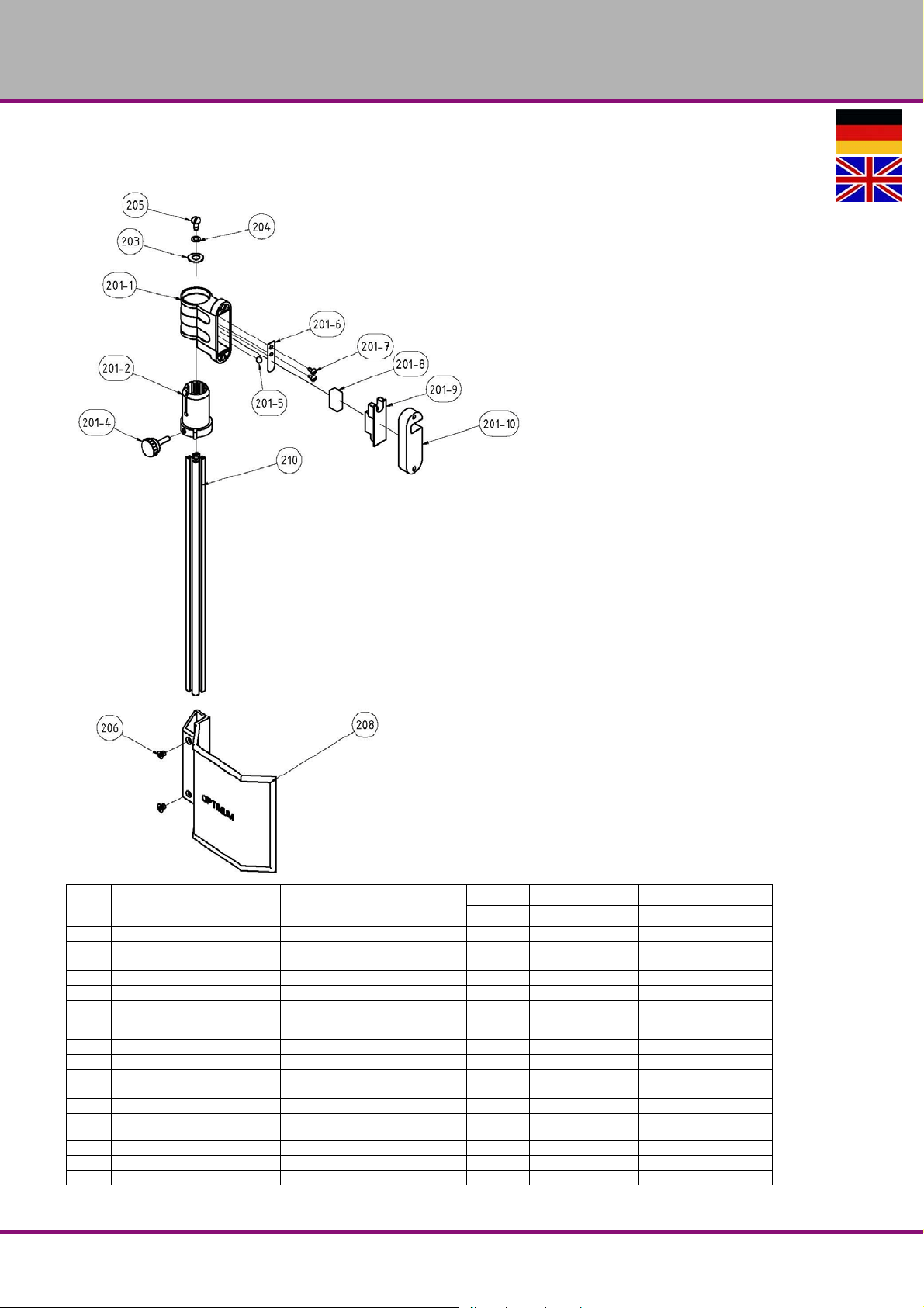
OPTIMUM
MASCHINEN - GERMANY
7.4.2 Bohrfutterschutz alter Typ - Drill chuck protection old type - B33Pro
Pos.
Bezeichnung Designation
201-1 Gehäuse Housing 1 030031712011
201-2 Aluminium Profilaufnahme Aluminium profile admission 1 030031712012
201-4 Klemmschraube Clamping screw 1 030031712014
201-5 Stahlkugel Steel ball 1 030031712015
201-6 Federblech Spring plate 1 030031712016
201-7 Flachkopfschraube Cheese head screw 2
201-8 Mikroschalter Microswitch 1 SQ1-HY50 030031712018
201-9 Deckel Cover 1 030031712019
201-10 Abstandsplatte Distance plate 1 0300317120110
203 Scheibe Washer 1 GB 955-87 - 10 03003171203
204 Scheibe Washer 1 GB 955-87 - 6 03003171204
205 Flachkopfschraube Cheese head screw 1
206 Senkschraube Countersunk screw 2 GB 819-85 - M6x8 03003171206
208 Schutz Protection 1 155mm 03011233208
210 Aluminiumprofil Aluminium profile 1 385mm 03003333210
B17Pro | B23Pro | B26Pro | B33ProDE | GB
Ersatzteile - Spare parts - B17Pro, B23Pro, B26Pro, B33Pro - (Vario)
Menge Grösse Artikelnummer
Qty. Size Item no.
ANSI/ASME
B18.6.5M - M4x0.7 x
B18.6.5M - M6x1 x 13
8
ANSI/ASME
030031712017
03003171205
Version 2.0.2 2014-11-04 68 Originalbetriebsanleitung
Page 69
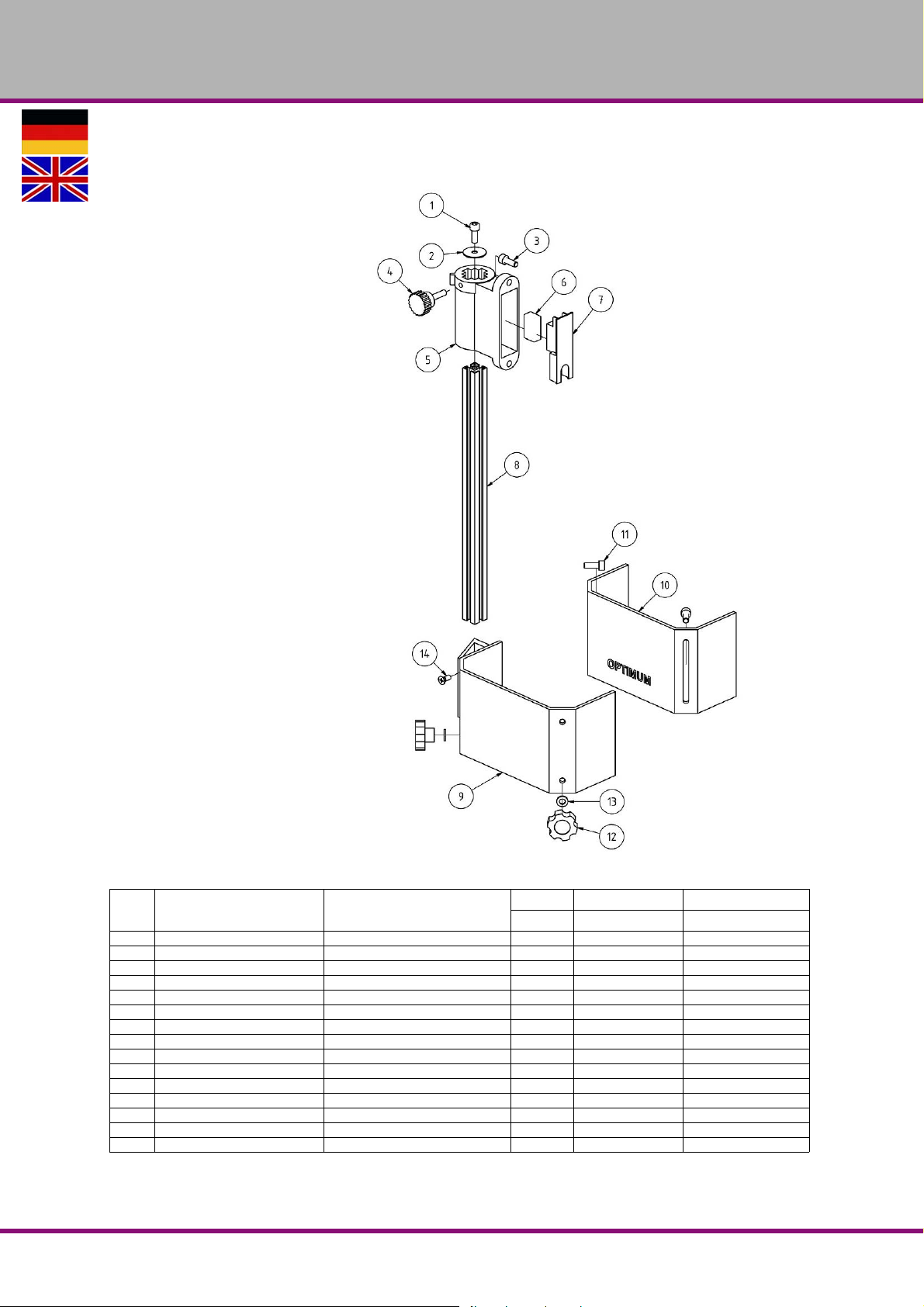
OPTIMUM
MASCHINEN - GERMANY
7.4.3 Bohrfutterschutz neuer Typ - Drill chuck protection new type - B33Pro
Pos.
Bezeichnung Designation
1 Innensechskantschraube Socket head screw 1 GB 70-85 - M6 x 10
2 Scheibe Washer 1 03020333123
3 Innensechskantschraube Socket head screw 2 GB 70-85 - M6 x 16
4 Rändelschraube Knurled screw 1 03020333125
5 Halterung Fixture 1 03020333126
6 Mikroschalter Microswitch 1 03020333127
7 Platte Plate 1 03020333128
8 Alu- Profil Aluminium profile 1 03003171202
9 Bohrfutterschutz A Drillig chuck safety A 1 03003171209
10 Bohrfutterschutz B Drillig chuck safety B 1 03003171210
11 Innensechskantschraube Socket head screw 2 GB 70-85 - M6 x 16
12 Rändelschraube Knurled screw 2 03003171212
13 Scheibe Washer 2 6 03003171213
14 Schraube Screw 2 M6x16
Halterung kpl. Holder cpl. 1 03008131201CPL
Ersatzteile - Spare parts - B17Pro, B23Pro, B26Pro, B33Pro - (Vario)
Version 2.0.2 2014-11-04 69Originalbetriebsanleitung
Menge Grösse Artikelnummer
Qty. Size Item no.
B17Pro | B23Pro | B26Pro | B33Pro DE | GB
Page 70
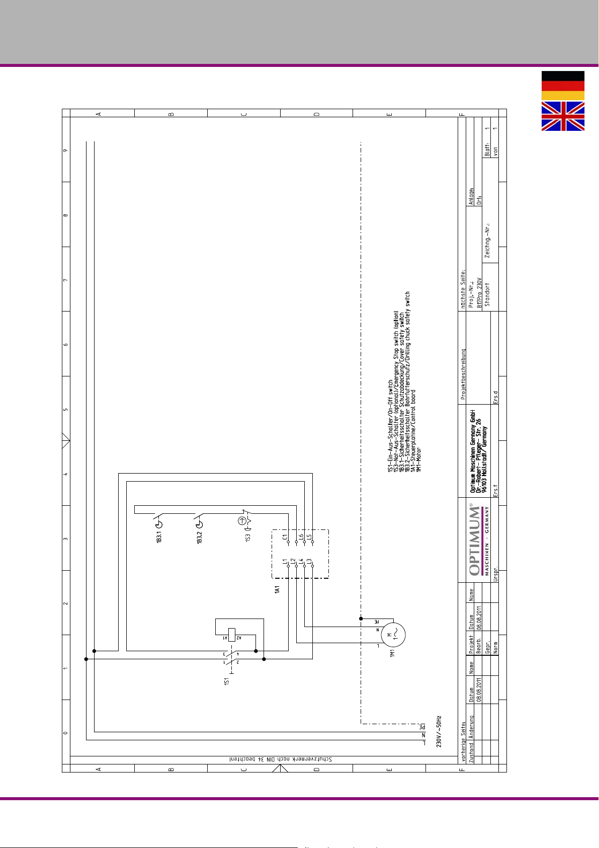
OPTIMUM
MASCHINEN - GERMANY
7.5 Schaltplan - Wiring diagram - B17Pro, B23Pro - 230V
B17Pro | B23Pro | B26Pro | B33ProDE | GB
Ersatzteile - Spare parts - B17Pro, B23Pro, B26Pro, B33Pro - (Vario)
Version 2.0.2 2014-11-04 70 Originalbetriebsanleitung
Page 71
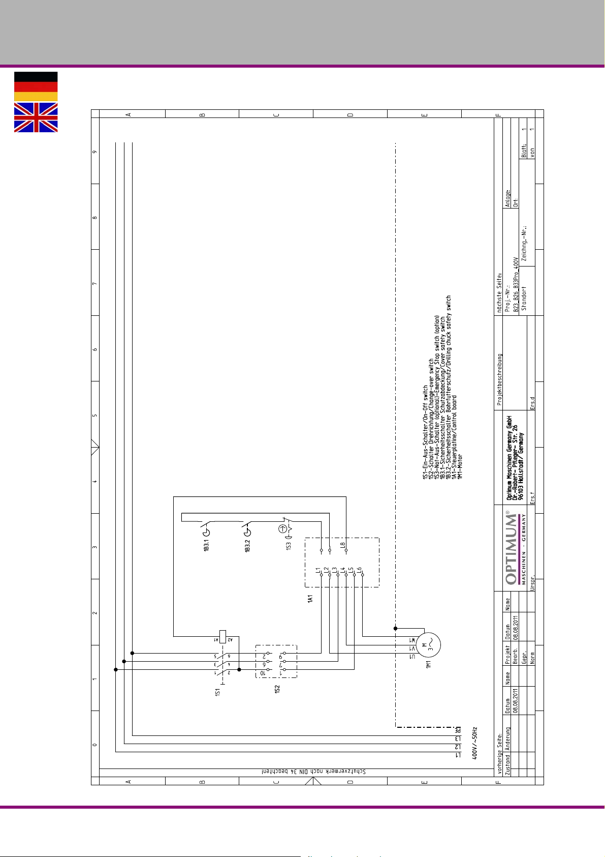
OPTIMUM
MASCHINEN - GERMANY
7.6 Schaltplan - Wiring diagram - B23Pro, B26Pro, B33Pro - 400 V
Ersatzteile - Spare parts - B17Pro, B23Pro, B26Pro, B33Pro - (Vario)
Version 2.0.2 2014-11-04 71Originalbetriebsanleitung
B17Pro | B23Pro | B26Pro | B33Pro DE | GB
Page 72
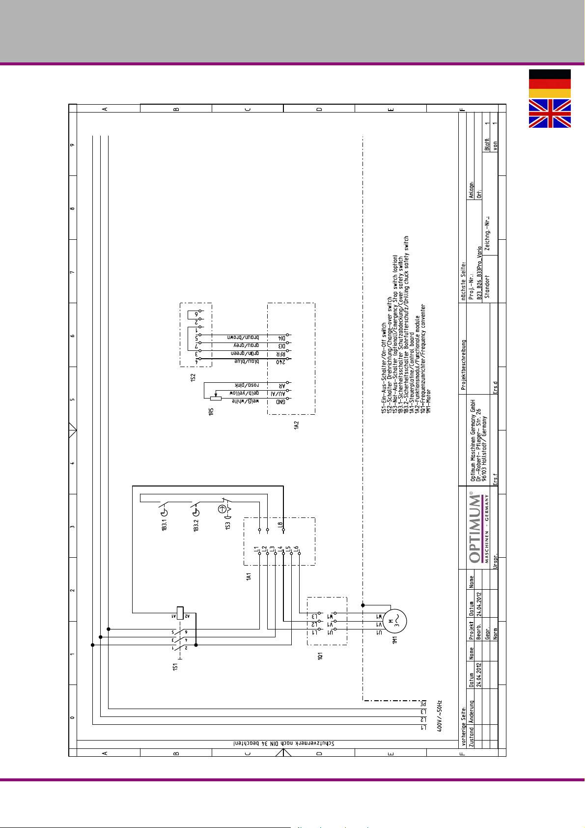
OPTIMUM
MASCHINEN - GERMANY
7.7 Schaltplan - Wiring diagram - B23Pro Vario, B26Pro Vario, B33Pro Vario
B17Pro | B23Pro | B26Pro | B33ProDE | GB
Ersatzteile - Spare parts - B17Pro, B23Pro, B26Pro, B33Pro - (Vario)
Version 2.0.2 2014-11-04 72 Originalbetriebsanleitung
Page 73
8 Malfunctions
8.1 Malfunctions on the drilling machine
OPTIMUM
MASCHINEN - GERMANY
Malfunction
Release of the FI protected
switch
Noise during work. • Spindle turning dry
Drill bit "burnt“ • Incorrect speed
Drill point runs off, drilled hole
is not circular.
Drill bit defective. • No base / support used. • Place a piece of wood underneath
Drill bit runs unround or wobbles.
Cause/
possible effects
• an unusual
FI protective switch is being used
• Tool blunt or incorrectly secured
• The filings have not been removed
from the bore hole
• Blunt drill bit.
• Operating without cooling agent
• Hard fibre in wood or length of the
cutting twist or the drill bit is uneven.
• Drill bit is bent.
• Drill bit is bent.
• Worn bearing on boring head.
• Drill is not correctly clamped.
• Drill chuck defective
Solution
• "Power supply“ on page 29
• Grease spindle
• Use new tool and check securing
(fixed setting of the bit, bit holder and
chuck).
• Select another rate, feed too high
• Retract the drill bit from the bore hole
more often.
• Sharpen the drill bit or insert new drill
bit.
• Use cooling agent
• Use a new drill bit.
the workpiece and fasten this to the
workpiece.
• Replace drill bit
• Have the bearing on the boring head
replaced.
• Set the correct tension to the drill bit.
• Exchange the drill chuck.
The drill chuck or the taper
mandril cannot be inserted.
Motor does not start • Moto r is wrongly conn ected
Motor is overheating and there
is no power
Precision of the work deficient • Heavy and unbalanced or deformed
Drilling spindle sleeve does not
return to its initial position
• Dirt, grease or oil on the taper inside
of the drill chuck or on the taper surface of the drill spindle
• Defective fuse
• Motor overloaded
• Too low mains voltage
• Motor is wrongly connected
part
• Inexact horizontal position of the part
holder
• Spindle return spring • “Spindle return spring“ on page 45
• Clean the surfaces accurately
• Keep surfaces free of grease
• Have it checked by authorised personnel.
• Disconnect immediately and have
the equipment checked by a trained
specialist
• Balance the piece statically and
secure without straining
• Adjust part-holder
Malfunctions
Version 2.0.2 2014-11-04 Page 73Original operating instructions
B17Pro | B23Pro | B26Pro | B33Pro GB
Page 74

OPTIMUM
MASCHINEN - GERMANY
9Annex
9.1 Copyright
This document is copyright. All derived rights are also reserved, especially those of translation,
re-printing, use of figures, broadcast, reproduction by photo-mechanical or similar means and
recording in data processing systems, neither partial nor total.
Subject to technical changes without notice.
9.2 Terminology/Glossary
Term Explanation
Drill sleeve Fixed hollow shaft in which the drilling spindle turns
Drilling spindle Shaft activated by the motor
Quick-action drill chuck Drill chuck can be fixed by hand.
Drill chuck Drill bit chuck
Drill drift Tool to release the bit or the dr ill chuck from the drill spindle
Taper mandrel Cone of the drill or of the drill chuck
Tool Milling cutter, drill bit, countersink, etc.
Workpiece Workpiece to be turned drilled or machined.
Drilling table Supporting surface, clamping surface
Drill head upper part of the drilling machine
Star wheel Ma nual operation for the drill feed
9.3 Change information manual
Chapter Short note new version no.
EC declaration changed standard 1.2.9
All Merging of standard + Vario 2.0
3 Image switch of drill chuck protection 2.0.1
1 + 4 Type plates + speed tables 2.0.2
B17Pro | B23Pro | B26Pro | B33ProGB
Version 2.0.2 2014-11-04Page 74 Original operating instructions
Annex
Page 75

OPTIMUM
MASCHINEN - GERMANY
9.4 Liability claims for defects / warranty
Beside the legal liability claims for defects of the customer towards the seller the manufacturer
of the product, OPTIMUM GmbH, Robert-Pfleger-Straße 26, D-96103 Hallstadt, does not grant
any further warranties unless they are listed below or had been promised in the frame of a
individual contractual agreement.
The processing of the liability claims or of the warranty is performed as chosen by
OPTIMUM GmbH either directly or through one of its dealers.
Any defective products or components of such products will either be repaired or
replaced by components which are free from defects. The property of replaced products or components passes on to OPTIMUM GmbH.
The automatically generated original proof of purchase which shows the date of purchase,
the type of machine and the serial number, if applicable, is the precondition in order to
assert liability or warranty claims. If the original proof of purchase is not presented, we are
not able to perform any services.
Defects resulting from the following circumstances are excluded from liability and warranty
claims:
- Using the product beyond the technical options and proper use, in particular due to overstraining of the machine
- Any defects arising by one's own fault due to faulty operations or if the operating manual
is disregarded
- Inattentive or incorrect handling and use of improper equipment
- Non-authorised modifications and repairs
- Insufficient installation and safeguarding of the machine
- Disregarding the installation requirements and conditions of use
- Atmospheric discharges, overvoltage and lightning strokes as well as chemical influences
The following items are as well not subject to the liability or warranty claims:
- Wearing parts and components which are subject to a standard wear as intended such
as e.g. V-belts, ball bearings, illuminants, filters, sealings, etc.
- Non reproducible software errors
Any services which OPTIMUM Gm bH or one of its servants performs in order to fulfil in the
frame of an additional guarantee are neither an acceptance of the defects nor an acceptance of its obligation to compensate. Such services do neither delay nor interrupt the warranty period.
Place of jurisdiction among traders is Bamberg.
If one of the above ment ioned agreemen ts is totally or partially inefficient and/or null, it is
considered as agreed what is closest to the will of the warrantor and which remains in the
framework of the limits of liability and warranty which are predefined by this contract.
9.5 Advice for disposal / Options of re-use
Please dispose of your machine in an environmentally friendly way, not by disposing of the
waste not in the environment, but by acting in a professional way.
Please do not throw away the packaging and the used machine later on, but dispose of your
material according to the guidelines established by your municipality or by the responsible
waste management company.
Annex
Version 2.0.2 2014-11-04 Page 75Original operating instructions
B17Pro | B23Pro | B26Pro | B33Pro GB
Page 76

OPTIMUM
MASCHINEN - GERMANY
9.5.1 Decommissioning
CAUTION!
Immediately decommission used machines in order to avoid later misuse and
endangering of the environment or of persons.
Disconnect the machine from the mains.
Cut the connecting cable into two.
Remove all operating materials from the used device which are harmful to the environment.
If required, remove the batteries and accumulators.
If required, disassemble the machine into easy-to-handle and usable components and
parts.
Supply the machine components and operating materials to the provided disposal routes.
9.5.2 Disposal of the packaging of the new machine
All used packaging materials and packaging aids of the machine are recyclable and generally
need to be transported to the material recycling.
The packaging wood can be supplied to the disposal or reuse.
It is possible to crush any packaging material made of cardboard and supply it to the waste
paper collection.
The films are made of polyethylene (PE) and the upholstery parts are made of polystyrene
(PS). It is possible to reuse these materials after reconditioning, if you supply them to the collection station or to the responsible waste management company.
Supply the packaging material only correctly sorted, so that it is possible to directly supply it to
the reuse.
9.5.3 Disposal of the used machine
INFORMATION
Please take care in your interest and in the interest of the environment that all component parts
of the machine are only disposed of in the intended and admitted way.
Please note that electrical devices includ e a number of reusable materials as well as components which are harmful to the environment. Please help that these components are disposed
of separately and professionally. In case of doubt, please contact your municipal waste management company. If necessary contact a specialised waste disposal centre to get help for the
disposal.
9.5.4 Disposal of electrical and electronic components
Please make sure that the electrical components are disposed of professionally and according
to the legal regulations.
The machine is composed of electrical and electronic components and must not be disposed of
as household waste. According to the European directive 2002/96/EC regarding electrical and
electronic used devices and the implementation of national legislation used power tools and
electrical machines need to be collected separately and supplied to an environmentally friendly
recycling centre.
Being the machine operator, you should gather information regarding the authorised collection
or disposal system which applies for your company.
Please make sure that batteries and/or accumulators are disposed of in a professional way and
according to the legal regulations. Please throw empty accumulators only into the collection
boxes of retail markets or municipal waste disposal companies.
B17Pro | B23Pro | B26Pro | B33ProGB
Version 2.0.2 2014-11-04Page 76 Original operating instructions
Annex
Page 77
OPTIMUM
MASCHINEN - GERMANY
9.5.5 Disposal of lubricants and cooling lubricants
ATTENTION!
Please imperatively make sure that the used coolants and lubricants are disposed of in
an environmentally friendly way. Observe the disposal advices of your municipal waste
management companies.
INFORMATION
Do not mix up used coolant emulsions and oils, since only used oils which had not been mixed
up are recyclable.
The disposal advices for the used lubricants are made available by the manufacturer for lubricants. If necessary, ask for the product-specific data sheets.
9.6 Disposal via municipal collecting points
Disposal of used electrical and electronic components
Disposal of used electric and electronic devices(Applicable in the countries of the European
Union and other European countries with a separate collecting system for such devices).
The sign on the product or on its packing indicates that the product must not be handled as
common household waist, but that it needs to be delivered to a central collection point for
recycling. Your contribution to the correct disposal of this product will protect the environment
and the health of your fellow men. The environment and the health are endangered by incorrect
disposal. Recycling of material will help to reduce the consumption of raw materials. Your District Office, the municipal waste collection station or the shop where you have bought the product will inform you about the recycling of this product.
9.7 RoHS , 2002/95/CE
The sign on the product or on its packaging indicates that this product complies with the
European guideline 2002/95/EC.
9.8 Product follow-up
We have a follow-up service for our products which extends even after shipment.
We would be grateful if you could send us the following information:
Modified settings
experiences with the bench drill and upright drill, which could be important for other users
Recurring failures
Optimum Maschinen Germany GmbH
Dr.-Robert-Pfleger-Str. 26
D-96103 Hallstadt
Telefax +49 (0) 951 - 96 555 - 888
E-Mail: [email protected]
Annex
Version 2.0.2 2014-11-04 Page 77Original operating instructions
B17Pro | B23Pro | B26Pro | B33Pro GB
Page 78
OPTIMUM
Hallstadt, 2014-10-24
Kilian Stürmer
(CEO, General manager)
MASCHINEN - GERMANY
9.9 EC - Declaration of Conformity B17Pro
The manufacturer /
retailer:
hereby declares that the following product,
Product designation: Bench drilling machine
Type designation:
Serial number: _ __ __ __ __
Year of construction: 20__
all relevant provisions of the Machinery Directive (2006/42/EC) corresponds.
The machine continues to comply with all provisions of the Directives Electrical equipment (2014/35/EC)
and electromagnetic compatibility (2014/30/EC).
The following harmonized standards were applied:
EN 12717:2001+A1:2009 Safety of machine to ols - drilling machines
EN ISO 12100:2010 Safety of machines - General design principles - Risk evaluation and risk
EN 60204-1 Safety of machinery - electrical equipment of machines, Part 1: general
Optimum Maschinen Germany GmbH
Dr.-Robert-Pfleger-Str. 26
D - 96103 Hallstadt
B17Pro
reduction
requirements
Person responsible for the document: Kilian Stürmer, Phone: +49 (0) 951 96 555-800
Address: Dr.-Robert-Pfleger-Str. 26
D - 96103 Hallstadt
B17Pro | B23Pro | B26Pro | B33ProGB
Version 2.0.2 2014-11-04Page 78 Original operating instructions
Page 79

9.10 EC - Declaration of Conformity B23Pro
Hallstadt, 2014-10-24
Kilian Stürmer
(CEO, General manager)
OPTIMUM
MASCHINEN - GERMANY
The manufacturer /
retailer:
hereby declares that the following product
Product designation: Bench drilling machine
Type designation:
Serial number: _ __ __ __ __
Year of construction: 20__
all relevant provisions of the Machinery Directive (2006/42/E C) corresponds.
The machine continues to comply with all provisions of the Directives Electrical equipment (2014/35/EC)
and electromagnetic compatib il ity (20 14/ 30 /EC).
The following harmonized standards were applied:
EN 12717:2001+A1:2009 Safety of machine tools - drilling machines
EN ISO 12100:2010 Safety of machines - General design principles - Risk evaluation and risk
EN 60204-1 Safety of machinery - electrical equipment of machines, Part 1: general
Optimum Maschinen Germany GmbH
Dr.-Robert-Pfleger-Str. 26
D - 96103 Hallstadt
B23Pro
reduction
requirements
Person responsible for the document: Kilian Stürmer, Phone: +49 (0) 951 96 555-800
Address: Dr.-Robert-Pfleger-Str. 26
D - 96103 Hallstadt
Version 2.0.2 2014-11-04 Page 79Original operating instructions
B17Pro | B23Pro | B26Pro | B33Pro GB
Page 80
OPTIMUM
Hallstadt, 2014-10-24
Kilian Stürmer
(CEO, General manager)
MASCHINEN - GERMANY
9.11 EC - Declaration of Conformity B23Pro Vario
The manufacturer /
retailer:
hereby declares that the following product
Product designation: Bench drilling machine
Type designation:
Serial number: _ __ __ __ __
Year of construction: 20__
all relevant provisions of the Machinery Directive (2006/42/EC) corresponds.
The machine continues to comply with all provisions of the Directives Electrical equipment (2014/35/EC)
and electromagnetic compatibility (2014/30/EC).
The following harmonized standards were applied:
EN 12717:2001+A1:2009 Safety of machine tools - drilling machines
EN ISO 12100:2010 Safety of machines - General design principles - Risk evaluation and risk
EN 60204-1 Safety of machinery - electrical equipment of machines, Part 1: general
Optimum Maschinen Germany GmbH
Dr.-Robert-Pfleger-Str. 26
D - 96103 Hallstadt
B23Pro Vario
reduction
requirements
EN 55011 class A: 2003.-08 Industrial, scientific radio-frequency equipment.
Person responsible for the document: Kilian Stürmer, Phone: +49 (0) 951 96 555-800
Address: Dr.-Robert-Pfleger-Str. 26
D - 96103 Hallstadt
B17Pro | B23Pro | B26Pro | B33ProGB
Version 2.0.2 2014-11-04Page 80 Original operating instructions
Page 81

9.12 EC - Declaration of Conformity B26Pro
Hallstadt, 2014-10-24
Kilian Stürmer
(CEO, General manager)
OPTIMUM
MASCHINEN - GERMANY
The manufacturer /
retailer:
hereby declares that the following product
Product designation: Upright drilling machine
Type designation:
Serial number: _ __ __ __ __
Year of construction: 20__
all relevant provisions of the Machinery Directive (2006/42/E C) corresponds.
The machine continues to comply with all provisions of the Directives Electrical equipment (2014/35/EC)
and electromagnetic compatib il ity (20 14/ 30 /EC).
The following harmonized standards were applied:
EN 12717:2001+A1:2009 Safety of machine tools - drilling machines
EN ISO 12100:2010 Safety of machines - General design principles - Risk evaluation and risk
EN 60204-1 Safety of machinery - electrical equipment of machines, Part 1: general
Optimum Maschinen Germany GmbH
Dr.-Robert-Pfleger-Str. 26
D - 96103 Hallstadt
B26Pro
reduction
requirements
Person responsible for the document: Kilian Stürmer, Phone: +49 (0) 951 96 555-800
Address: Dr.-Robert-Pfleger-Str. 26
D - 96103 Hallstadt
Version 2.0.2 2014-11-04 Page 81Original operating instructions
B17Pro | B23Pro | B26Pro | B33Pro GB
Page 82
OPTIMUM
Hallstadt, 2014-10-24
Kilian Stürmer
(CEO, General manager)
MASCHINEN - GERMANY
9.13 EC - Declaration of Conformity B26Pro Vario
The manufacturer /
retailer:
hereby declares that the following product
Product designation: Upright drilling machine
Type designation:
Serial number: _ __ __ __ __
Year of construction: 20__
all relevant provisions of the Machinery Directive (2006/42/EC) corresponds.
The machine continues to comply with all provisions of the Directives Electrical equipment (2014/35/EC)
and electromagnetic compatibility (2014/30/EC).
The following harmonized standards were applied:
EN 12717:2001+A1:2009 Safety of machine tools - drilling machines
EN ISO 12100:2010 Safety of machines - General design principles - Risk evaluation and risk
EN 60204-1 Safety of machinery - electrical equipment of machines, Part 1: general
Optimum Maschinen Germany GmbH
Dr.-Robert-Pfleger-Str. 26
D - 96103 Hallstadt
B26Pro Vario
reduction
requirements
EN 55011 class A: 2003.-08 Industrial, scientific radio-frequency equipment.
Person responsible for the document: Kilian Stürmer, Phone: +49 (0) 951 96 555-800
Address: Dr.-Robert-Pfleger-Str. 26
D - 96103 Hallstadt
B17Pro | B23Pro | B26Pro | B33ProGB
Version 2.0.2 2014-11-04Page 82 Original operating instructions
Page 83
9.14 EC - Declaration of Conformity B33Pro
Hallstadt, 2014-10-24
Kilian Stürmer
(CEO, General manager)
OPTIMUM
MASCHINEN - GERMANY
The manufacturer /
retailer:
hereby declares that the following product
Product designation: Upright drilling machine
Type designation:
Serial number: _ __ __ __ __
Year of construction: 20__
all relevant provisions of the Machinery Directive (2006/42/E C) corresponds.
The machine continues to comply with all provisions of the Directives Electrical equipment (2014/35/EC)
and electromagnetic compatib il ity (20 14/ 30 /EC).
The following harmonized standards were applied:
EN 12717:2001+A1:2009 Safety of machine tools - drilling machines
EN ISO 12100:2010 Safety of machines - General design principles - Risk evaluation and risk
EN 60204-1 Safety of machinery - electrical equipment of machines, Part 1: general
Optimum Maschinen Germany GmbH
Dr.-Robert-Pfleger-Str. 26
D - 96103 Hallstadt
B33Pro
reduction
requirements
Person responsible for the document: Kilian Stürmer, Phone: +49 (0) 951 96 555-800
Address: Dr.-Robert-Pfleger-Str. 26
D - 96103 Hallstadt
Version 2.0.2 2014-11-04 Page 83Original operating instructions
B17Pro | B23Pro | B26Pro | B33Pro GB
Page 84
OPTIMUM
Hallstadt, 2014-10-24
Kilian Stürmer
(CEO, General manager)
MASCHINEN - GERMANY
9.15 EC - Declaration of Conformity B33Pro Vario
The manufacturer /
retailer:
hereby declares that the following product,
Product designation: Upright drilling machine
Type designation:
Serial number: _ __ __ __ __
Year of construction: 20__
all relevant provisions of the Machinery Directive (2006/42/EC) corresponds.
The machine continues to comply with all provisions of the Directives Electrical equipment (2014/35/EC)
and electromagnetic compatibility (2014/30/EC).
The following harmonized standards were applied:
EN 12717:2001+A1:2009 Safety of machine tools - drilling machines
EN ISO 12100:2010 Safety of machines - General design principles - Risk evaluation and
EN 60204-1 Safety of machinery - electrical equipment of machines, Part 1: general
Optimum Maschinen Germany GmbH
Dr.-Robert-Pfleger-Str. 26
D - 96103 Hallstadt
B33Pro Vario
risk reduction
requirements
EN 55011 class A: 2003.-08 Industrial, scientific radio-frequency equipment
Person responsible for the document: Kilian Stürmer, Phone: +49 (0) 951 96 555-800
Address: Dr.-Robert-Pfleger-Str. 26
D - 96103 Hallstadt
B17Pro | B23Pro | B26Pro | B33ProGB
Version 2.0.2 2014-11-04Page 84 Original operating instructions
Page 85

Index
OPTIMUM
MASCHINEN - GERMANY
A
Accident report ....................................................18
Assembly
............................................................22
C
Classification
of hazards
Customer service
Customer service technician
........................................................8
................................................46
...............................46
D
Disposal ..............................................................77
Drill chuck
assembly
disassembly
........................................................38
...................................................38
E
EC Declaration of Conformity 77, 78, 79, 80, 81, 82,
83, .......................................................................84
Electrical connection
Electrical system
safety
.............................................................18
...........................................30
I
Inspection ............................................................43
Intended use
.........................................................9
M
Maintenance .......................................................43
Malfunctions drilling machine
Misuse
.................................................................10
..............................73
O
Obligations
of the operating company
of the operator
Operator positions
...............................................12
...............................................13
..............................12
P
Pictograms ............................................................9
Protective
equipment
......................................................16
Q
Qualification of the staff
safety
.............................................................11
R
Repair .................................................................43
RoHS
..................................................................77
S
Safety
devices
during maintenance
during operation
Safety instructions
Scope of delivery
Specialist dealer
Storage and packaging
Switching off
the machine
Switching on
...........................................................13
.......................................17
.............................................17
.................................................8
................................................22
..................................................46
.......................................23
...................................................37
the machine
...................................................37
T
Table cutting speeds ..........................................40
Technical data
Emissions
Tool
disassembly
......................................................20
...................................................38
W
Warming up the machine ....................................30
Warning notes
......................................................8
Version 2.0.2 2014-11-04 Page 85Original operating instructions
B17Pro | B23Pro | B26Pro | B33Pro GB
Page 86

OPTIMUM
MASCHINEN - GERMANY
B17Pro | B23Pro | B26Pro | B33ProGB
Version 2.0.2 2014-11-04Page 86 Original operating instructions
 Loading...