

Page 1
OPTIMUM
MASCHINEN - GERMANY
Operating manual
Version 1.0.1
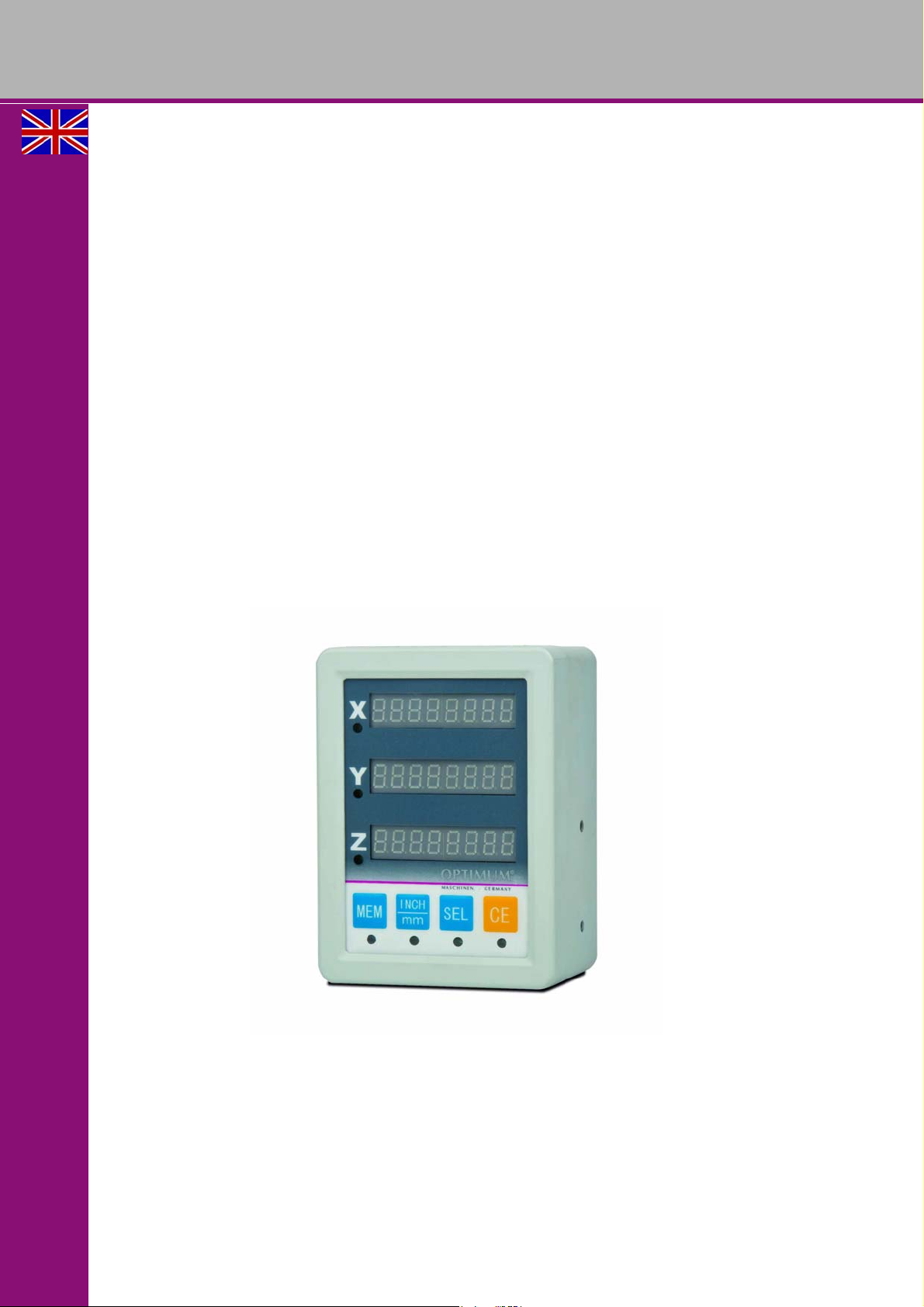
Digital position display
DRO 3
GB
Page 2

OPTIMUM
MASCHINEN - GERMANY
Inhaltsverzeichnis
1 Safety
1.1 Target group.............................................................................................................................................4
1.2 Intended use.............................................................................................................................................4
1.3 Invalid modification of the device..............................................................................................................5
1.4 Possible dangers caused by machine tools..............................................................................................5
1.5 Possible dangers caused by the device ...................................................................................................5
1.6 Authorized staff.........................................................................................................................................5
1.7 Additional requirements regarding the qualification..................................................................................6
1.8 Obligations of the operating company......................................................................................................6
1.9 Obligations of the operator .......................................................................................................................6
1.10 Safety during operation.............................................................................................................................6
1.11 Safety during maintenance.......................................................................................................................6
1.11.1 Disconnecting and making it safe..................................................................................................6
1.12 Accident report............................................ ... .................................... .......................................................6
1.13 General instruction....................................................................................................................................7
1.13.1 Technical data.......................................................... ... ..................................................................7
1.13.2 Working conditions........................................................................................................................7
1.13.3 Precautions ...................................................................................................................................7
1.13.4 Regular maintenance....................................................................................................................7
2 Digital 3-axes position display DRO 3
2.1 The front panel..........................................................................................................................................8
2.2 The rear panel ..........................................................................................................................................8
2.3 Description of the keys .............................................................................................................................9
2.4 Measuring device - Pin Assignment .........................................................................................................9
2.5 Assembly and commissioning ................................................................. .. .............................................10
2.6 Scope of delivery....................................................................................................................................10
2.7 Storage...................................................................................................................................................10
2.8 Adding the device................................. ... ... ................................................................... .........................10
2.8.1 Requirements regarding the installation site ...............................................................................10
2.8. .2 Mounting the Display Unit
2.8.3 Assembling the measuring gauges..................................... ... .................................... ... ... ...........10
2.8.4 Assembly of the reading head.....................................................................................................11
2.9 First commissioning................................................................................................................................11
2.9.1 Connecting the measuring gauges..............................................................................................11
2.9.2 Connecting the power supply......................................................................................................11
2.9.3 Switching on the device...............................................................................................................12
2.10 Internal parameter setting.......................................................................................................................12
2.10.1 Change of counting direction.......................................................................................................12
2.10.2 Function diameter - radius...........................................................................................................12
2.10.3 Summing function of axes...........................................................................................................13
2.10.4 Change of resolution ...................................................................................................................13
3 Troubleshoot ing DRO 3
4 Annex
4.1 Copyright ................................................................................................................................................15
4.2 Liability claims for defects / warranty......................................................................................................15
4.3 Change information manual....................................................................................................................16
4.4 Advice for disposal / Options of re-use...................................................................................................16
4.4.1 Disposal of electrical and electronic components .......................................................................16
4.5 Disposal via municipal collecting points..................................................................................................16
4.6 RoHS, 2002/95/EC.................................. ... ...................................................................... ......................16
.......................................................................................................10
..............
DRO 3GB
Version 1.0.1 dated 2014-05-06Page 2 Original operating instructions
Inhaltsverzeichnis
Page 3

OPTIMUM
MASCHINEN - GERMANY
Preface
Dear customer,
Thank you very much for purchasing a product made by OPTIMUM.
OPTIMUM metal working machines offer a maximum of quality, technically optimum solutions and con-
vince by an outstanding price performance ratio. Continuous enhancements and product innovations guarantee state-of-the-art products and safety at any time.
Before commissioning the device please thoroughly read these operating instructions and get familiar with
the device. Please also make sure that all persons operating the device have read and understood the
operating instructions beforehand.
Keep these operating instructions in a safe place nearby the device.
Information
The operating instructions include indications for safety-relevant and proper installation, operation and
maintenance of the device. The continuous observance of all notes included in this manual guarantee the
safety of persons and of the device.
The manual determines the intended use of the device and includes all necessary information for its economic operation as well as its long service life.
The illustration and information included in the present manual can possibly deviate from the current state
of construction of your device. Being the manufacturer we are continuously seeking for improvements and
renewal of the products. Therefore, changes might be performed without prior notice. The illustrations of the
device may be different from the illustrations in these instructions with regard to a few details. However, this
does not have any influence on the operability of the device.
Therefore, no claims may be derived from the indications and descriptions. Changes and errors are
reserved!
Your suggestion with regard to these operating instructions are an important contribution to optimising our
work which we offer to our customers. For any questions or suggestions for improvement, please do not
hesitate to contact our service department.
If you have any further questions after reading these operating instructions and you are not able to
solve your problem with a help of these operating instructions, please contact your specialised
dealer or directly the company OPTIMUM.
Optimum Maschinen Germany GmbH
Dr.- Robert - Pfleger - Str. 26
D-96103 Hallstadt
Mail: [email protected]
Internet: www.optimum-maschinen.com
Preface
Version 1.0.1 dated 2014-05-06 Page 3Original operating instructions
DRO 3 GB
Page 4
OPTIMUM
MASCHINEN - GERMANY
1 Safety
Representation Conventions
This part of the operating instructions
In addition to these operation instructions, please observe
During installation, operation, maintenance and repair of the device, the European standards
need to be observed.
PLEASE KEEP THIS DOCUMENTATION ALWAYS CLOSE TO THE DEVICE.
INFORMATION
If you are unable to solve a problem using these operating instructions, please contact us for
advice:
Optimum Maschinen Germany GmbH
Dr. Robert-Pfleger-Str. 26
D- 96103 Hallstadt
email: [email protected]
gives additional advices
calls on you to act
enumerations
defines the intended use of the device,
points out the dangers that might arise for you or others if these instructions are not
observed,
informs you about how to avoid dangers.
the applicable laws and regulations,
legal regulations for accident prevention,
the prohibition, warning and mandatory signs as well as the warning labels on the device.
1.1 Target group
This operating manual is addressed to operation organizations, the operators and the maintenance staff.
1.2 Intended use
WARNING!
In the event of improper use, the digital position display
there may be a risk to the staff,
will endanger the device and other material property of the operator,
may affect proper operation of the device.
The device provided for the pos ition display of traveling tools respectively tool slides on lathes,
milling machines, etc. The device is designed and manufactured to be used universally in environments where there is no potential danger of explosion. For the operation, additionally absolute or incremental measuring systems for the position acquisition are required.
If the device is used in any way other than described above or modified without the approval of
the company Optimum Maschinen Germany GmbH then the device is being used improperly.
We do not take any liability for damages caused by intended use.
DRO 3GB
Version 1.0.1 dated 2014-05-06Page 20 Original operating instructions
Safety
Page 5
OPTIMUM
MASCHINEN - GERMANY
It is also part of proper use that the oper ating manual and in spection and mainte nance instructions are observed.
1.3 Invalid modification of the device
WARNING!
Extremely severe injuries.
It is forbidden to make any modifications or alterations to the operating values of the
device! They could endanger personnel working on the device and cause damage to the
device.
We expressly point out that the guarantee will expire due to any constructive technical or procedural changes which had not been performed by the company Optimum Maschinen Germany
GmbH.
1.4 Possible dangers caused by machine tools
The device is operated in immediate proximity of machine tools.
Always switch off the device and pull the mains plug when performing cleaning or maintenance work on the device or on the machine tool.
WARNING!
Machine tools must only be used with activated safety devices. Disconnect the machine
tool whenever you detect a failure in the safety devices or when they are not fitted!
1.5 Possible dangers caused by the device
The operating safety of digital position display has been tested. It has been designed and built
using the latest technological advances.
Nonetheless, there remains a residu al risk, since the device operates with electrical voltages
and currents.
We have used construction resources and safety techniques to minimize the health risk to personnel resulting from this hazard.
Nonetheless, if the device is operated or maintained by personnel who are not duly qualified,
there may be a risk resulting from incorrect operation or improper maintenance.
1.6 Authorized staff
Persons authorized to operate and maintain should be trained technical staff and instructed by
the ones who are working for the operating company and for the manufacturer.
All personnel involved in assembly, commissioning, operation and maintenance need to be duly
qualified and follow this operating manual.
Safety
Version 1.0.1 dated 2014-05-06 Page 21Original operating instructions
DRO 3 GB
Page 6
OPTIMUM
MASCHINEN - GERMANY
1.7 Additional requirements regarding the qualification
Work on electric components or equipment must only be carried out by qualified electricians.
1.8 Obligations of the operating company
The operator must instruct the staff on all safety standards that apply to the device and to the
operation.
1.9 Obligations of the operator
The operator must
have read and understood the operating instructions,
be familiar with all safety devices and instructions,
be capable of operating the device.
1.10 Safety during operation
Check the digital position display at least once per shift. Inform the person responsible immediately of any damage, defect or change in operating function.
WARNING!
Before activating the device, double-check that this will, even in combination with the
machine tool, not
lead to any danger with respect to people,
cause any damage to equipment.
Avoid any unsafe working practices:
Do not work on the device or the machine if your concentration is reduced, for example,
because you are taking medication.
Observe the accident prevention regulations issued by your Employers Liability Insurance
Association or other competent supervisory authority, responsible for your company.
1.11 Safety during maintenance
Inform operators timely on maintenanc e an d re pa ir work .
Report all safety-relevant changes or performance details of the device. Document all changes,
have the operating manual changed accordingly and train the machine operators.
1.11.1 Disconnecting and making it safe
Switch off the device before starting any maintenance or repair work.
Pull the mains plug.
Place a warning sign on the machine tool.
1.12 Accident report
Inform your superiors and Optimum Maschinen Germany GmbH immediately in the event of
accidents, possible sources of danger and any actions which almost led to an accident (near
misses) that are connected with the digital position display and the machine tool.
DRO 3GB
Version 1.0.1 dated 2014-05-06Page 22 Original operating instructions
Safety
Page 7

OPTIMUM
MASCHINEN - GERMANY
1.13 General instruction
This manual explains the installation, the operation and the maintenance of the position display
DRO 3 in detail, which is widely used as add-on to axis-driven machine tools.
1.13.1 Technical data
Technical data Mains voltage: AC 230V + - 10 %, 50 - 60Hz
Power consumption: about 5W, fuse 2A
Display: X, Y, Z axis with 8-digit LED display, where the first digit is for the algebraic sign.
1.13.2 Working conditions
Avoid exposing the device direct solar radiation or high temperatur es, and it should be us ed
in temperatures ranging from 0°C to 40°C;
Environment temperature for storage must be ranging from -30°C to 70°C;
Environmental relative humidity: <90% (at 20°C± 5°C); <90% (at 20°C± 5°C);
Keep away from high voltage, strong electric current and strong magnetic field;
Signal cable should be far away from the power cable;
Avoid working in environments with scrap iron, oil, water, dust and strong vibration;
Do not expose the position display to corros ively acting chemicals and hi ghly corrosive
acids or bases.
1.13.3 Precautions
When unpacking, perform a visual check if the position display is in good order. If anything
is out of order, please immediately contact our company or the distributor. Do not dismantle
the device by yourself in order to repair it;
Please do not connect the position display to any readers of other trademarks, otherwise it
may cause display errors or damages on the position display;
Please do not open the cover of the position display, do not remove the reader before hav-
ing disconnected the whole measuring system;
Make sure that the position display is well grounded.
1.13.4 Regular maintenance
Switch off the power before cleaning the position display;
Polish the cover with soft and dry cloth;
Do not clean the cover using abrasive cleaning agents or agents which would change the
surface of plastic materials;
Clean the display window at the front side of the position display using an neutral and antistatically acting cleaning agent.
Safety
Version 1.0.1 dated 2014-05-06 Page 23Original operating instructions
DRO 3 GB
Page 8
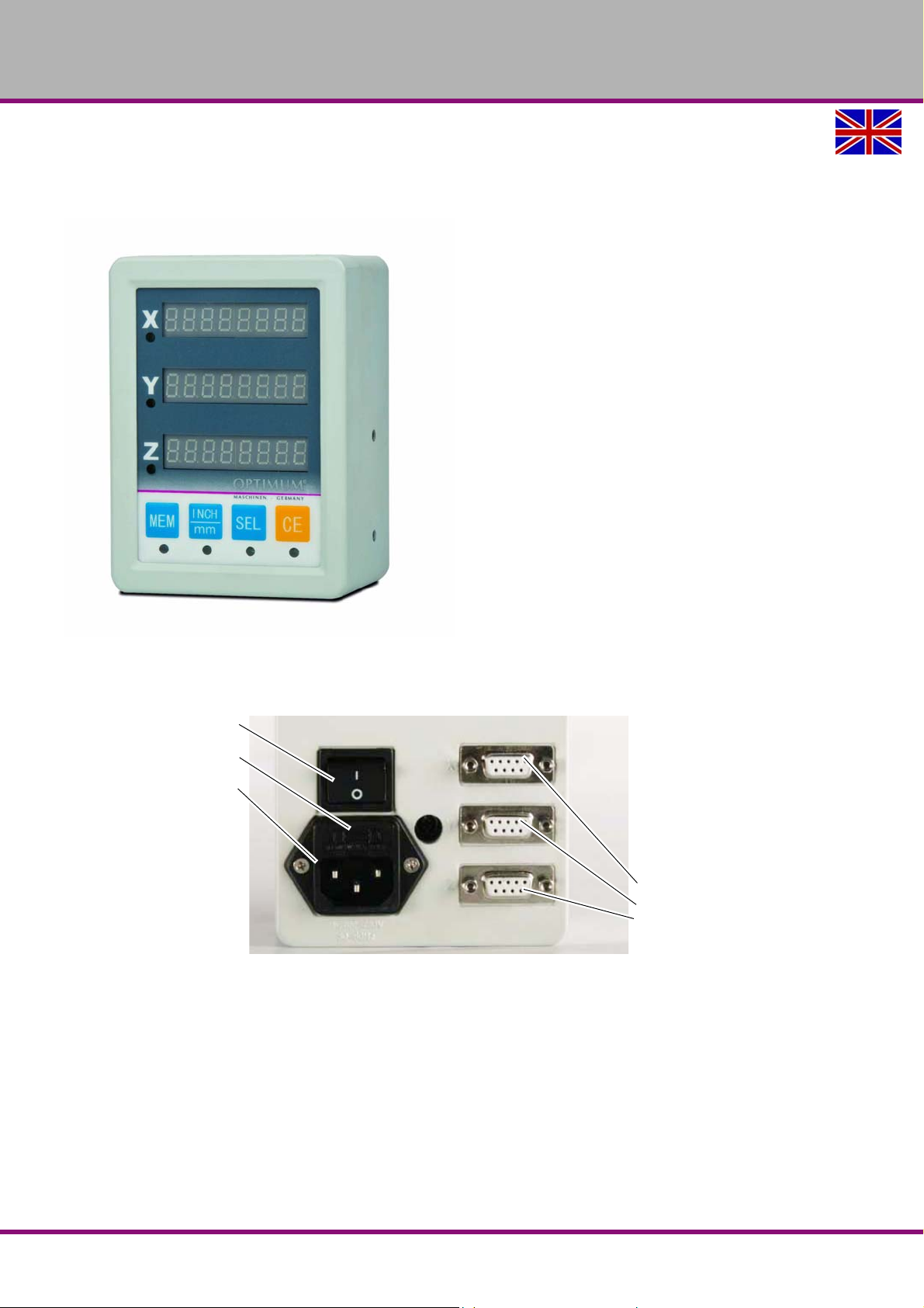
OPTIMUM
I/O switch
Fuse
Power supply
Interfaces for
data transfer:
X axis
Y axis
Z axis
MASCHINEN - GERMANY
2 Digital 3-axes position display DRO 3
2.1 The front panel
Img.2-1: front side DRO 3
2.2 The rear panel
Img.2-2: rear side DRO 3
DRO 3GB
Digital 3-axes position display DRO 3
Version 1.0.1 dated 2014-05-06Page 24 Original operating instructions
Page 9
OPTIMUM
MASCHINEN - GERMANY
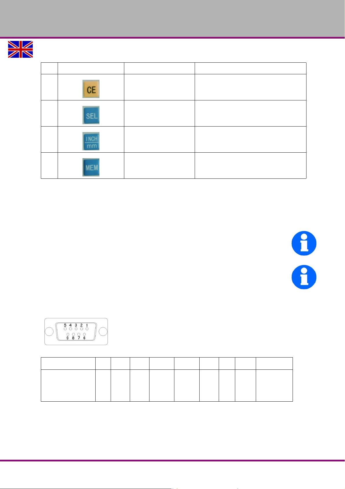
2.3 Description of the keys
No. Sign on the key Name of the key Function description
1
2
3
4
Delete key
SEL key To select the X/ Y/ Z coordinate axis
The metric / inch conver-
sion key
Programming key For internal parameter settings
To clear displayed value of a specific axis or
give up the current operation
To convert metric / inch
2.4 Measuring device - Pin Assignment
The functional designation of the wires, that each pin at the 9-Pin-SubD-plug is allocated, must
have the same assignment as the connector at the digital display. The assignment is shown in
the following tables.
INFORMATION
The DRO 3 is designated for the operation with measuring devices, that provides a Sine 1Vpp
output signal (= voltage between the upper and lower peak of the wave is 1 Volt).
INFORMATION
We are recommending the applic ation of original OPTIMUM measuring gibs, because this will
ensure a quick and failure-free operation.
If it is indented to operate the digital display with measuring devices from other manufacturers,
pay attention that this measuring gib is providing an output signal from the type „Sine 1Vpp“
and the pin assignment is consistent to the following table.
PIN No.
sine 1Vpp signal
for OPTIMUM
measuring gauge
ML
12 3 4 5 67 8 9
A+ A- +5V 0V B+ B- Z+ Z- Shielding
Digital 3-axes position display DRO 3
Version 1.0.1 dated 2014-05-06 Page 25Original operating instructions
DRO 3 GB
Page 10
OPTIMUM
MASCHINEN - GERMANY
2.5 Assembly and commissioning
INFORMATION
If you want to use the digital position display you need at least one measuring gauge. Measuring gauges are not part of the delivery volume of the digital position display.
Only use original OPTIMUM path-measuring systems, since the position display is only
adjusted to such path-measuring system and this way will guarantee a safe functioning.
2.6 Scope of delivery
Upon delivery immediately check if the device had been damaged during transport. Compare
the delivery volume with the data on the delivery note.
2.7 Storage
ATTENTION!
In case of wrong and improper storage components might get damaged and destroyed.
Store the packed or already unpacked device only at dry environmental conditions at a
temperature from 0 °C to 40 °C.
Consult Optimum Maschinen Germany GmbH if the device or accessories are stored for more
than three months or are stored under different environmental conditions than those given here.
2.8 Adding the device
2.8.1 Requirements regarding the installation site
ATTENTION!
When choosing the installation site, please take into account the length of the
connection lines for the measuring gauges.
The installation site needs to be dry and vibration-free and comply with the ergonomic requirements of a working place. Observe the safety instructions for working nearby machine tools.
The working area for the operation, maintenance and repair works must not be hindered by
adding the position display.
2.8.2 Mounting the Display Unit
The Display needs to be mounted securely to a horizontal or vertical surface in a location where it can be
used freely without overreaching any rotating or moving machine parts.
Supplied with the unit is a Plate Magnet that can be fastened with the 2 short metal screws provided to the
base or sides of the display allowing you to mount it to a metal surface easily.
There are 4 Extra nylon push in plugs provided. Ensure these are pushed into the remaining 4 holes before
connection to power to stop the ingress of dust, moisture and swarf .
If the Unit is mounted differently using the tapped holes provided, Caution Must be taken to ensure screws
used do not enter the unit more than 10mm, due to live 240 Volt parts inside. Ensure all remaining holes have
screws in before use and connection to power,
DRO 3GB
Version 1.0.1 dated 2014-05-06Page 26 Original operating instructions
Page 11

OPTIMUM
MASCHINEN - GERMANY
2.8.3 Assembling the measuring gauges
Measuring gauges are linear measuring systems which collect the position of mobile machine
parts via a sensor and forward them coded to the position display.
ATTENTION!
Only use path-measuring systems recommended by OPTIMUM. When assembling the
path-measuring systems imperatively follow the instructions of the manufacturer.
Before mounting it on the machine, check the operability of the measuring gauges. To do
so, use the digital position display DRO 3 or a similar device.
Install the measuring gauge in a way that it will not be damaged by cutting tools or coolants.
If required, mount a cover.
If possible, mount the enclosed measuring ga uge s with th e sea lin g lips sh ow ing dow nwa r d.
If possible, place the reading head stationary in order to avoid damages of the connection
lines by its movements.
ATTENTION!
The path-measuring system and its add-on pieces can cover important components on the
machine tool (e.g. lubricating nipples).
Before mounting the path-measuring systems, please note such limitations in functions and
make arrangements accordingly.
2.8.4 Assembly of the reading head
Mount a fixture for the reading head.
Fix the reading head to the fixture.
Remove possibly existing assembly aids from the reading head.
Check the orientation of the reading head using a dial gauge
(refer to the tolerances for the assembly given by the manufacturer).
Check if all components are moving freely.
2.9 First commissioning
WARNING!
When first commissioning the device by inexpert personal you will endanger persons or
the device.
We do not take any liability for damages caused by incorrectly performed
commissioning.
2.9.1 Connecting the measuring gauges
The measuring gauges are firmly connected to the rear side of the device using couplings.
Slightly press the plug of the path-measuring system on the coupling.
In doing so, turn the plug until the inner guiding pin of the plug has cammed in the g roove of
the coupling.
Firmly bolt the screw cap of the plug on the coupling.
2.9.2 Connecting the power supply
The device is connected using a power cable. The coupling for the power cable is at the rear
side of the device.
The plug of the power cable is provided for shock-proof sockets.
Please observe the technical indications regarding the electrical connection of the device.
"The rear panel“ on page 24
Version 1.0.1 dated 2014-05-06 Page 27Original operating instructions
DRO 3 GB
Page 12
OPTIMUM
MASCHINEN - GERMANY
2.9.3 Switching on the device
The device will be switched on using the main switch at the rear side.
ATTENTION!
Only switch on the device by using the main switch if the measuring gauges are
connected and the power cord is connected to the electrical power supply.
2.10 Internal parameter setting
The display is shipped from the factory with default programming. To change the default programming the device must be switched to the programming mode.
Factory setting:
Parameter Value Parameter setting
Resolution 0.005 mm R5
Counting direc-
tion
2.10.1 Change of counting direction
positive C0
Parameter Value How to change the parameter setting
Counting direction
Counting direction
C0
C1
Turn off the DRO 3 with the 1/0 switch.
1.
Press and hold the “MEM” button down while turning on the DRO
2.
with the 1/O switch
Change the value of "rd" to "1" or "0" by pressing the "INCH / mm"
3.
button. With the "SEL" button you can select the value in the individual axes.
4. Confirm the value by pressing the "MEM" button.
Each coordinate axis is shown her own set point value for the counting direction.
2.10.2 Function diameter - radius
Parameter Value How to change the parameter setting
rd 0 1. Turn off the DRO 3 with the 1/0 switch.
rd 1 2.
Press and hold the “MEM” button down while turning on the DRO
with the 1/O switch
Change the value of "rd" to "1" or "0" by pressing the "INCH / mm"
3.
button.
4. Confirm the value by pressing the "MEM" button.
When the X-axis indicates rd 0, the axis is set to radius function.
When the X-axis indicating rd 1, the axis is set to diameter function and shows the double
value.
Press the "INCH / mm" - button to switch the diameter function ON or OFF.
If the X-axis is set to diameter function, the LED lights below the "SEL" button.
DRO 3GB
Version 1.0.1 dated 2014-05-06Page 28 Original operating instructions
Page 13
OPTIMUM
MASCHINEN - GERMANY
2.10.3 Summing function of axes
Parameter Value How to change the parameter setting
SU 0 1. Turn off the DRO 3 with the 1/0 switch.
U 1 2.
If Y axis indicates SU 0, the Z and Y axes are not summed. The display is in the standard operating mode.
If the Y axis indicates SU 1, the axes Z and Y are summed.
Press the "INCH / mm" - button to switch the summing function of axes ON or OFF.
2.10.4 Change of resolution
Parameter Value How to change the parameter setting
Resolution 0.005 mm 1. Turn off the DRO 3 with the 1/0 switch.
Press and hold the “MEM” button down while turning on the DRO
with the 1/O switch
Change the value of "SU" to "1" or "0" by pressing the "INCH / mm"
3.
button.
4. Confirm the value by pressing the "MEM" button.
2.
Press and hold the “MEM” button down while turning on the DRO
with the 1/O switch
Change the value R5“ or „R1“ or „R10“ by pressing the "INCH / mm"
button.
Meaning:
3.
• R1 = 0.001 mm
• R5 = 0.005 mm
• R10 = 0.01 mm
4. With the "SEL" button you can select the value in the individual axes.
5. Confirm the value by pressing the "MEM" button.
INFORMATION
Modification of the current parameters can not be saved if there occur power failure or
the DRO 3 is turned off during the process of parameter setting.
Version 1.0.1 dated 2014-05-06 Page 29Original operating instructions
DRO 3 GB
Page 14

OPTIMUM
MASCHINEN - GERMANY
I. Functions of the Keys
1. The “MEM” key
Function 1: to show the coordinate values of volatile memory under normal working mode;
Function 2: to enter the parameter setting mode when starting the DRO and to confirm the modification
of parameters under the parameter setting mode.
2. The “INCH/mm” key
Function 1: to switch between INCH/mm under normal working mode;
Function2: to select parameter values under the parameter setting mode.
3. The “SEL” key
Function: to select coordinate.
4. The “CE” key
Function: to clear the displayed values of the selected coordinates under normal working mode.
To cancel the state of volatilememory.
II. Operating Instructions
1. Starting: When the DRO is started, it will show its type, software version number, etc. And after 2
seconds the DRO enters into the normal working interface. It will show the coordinate values of volatile
memory if any when it was switched off last time and the indicating light on the “MEM” key will shine. When
the machine tool works again, the indicating light on the “MEM” key will go out. If there was no coordinate
value of volatile memory when it was switched off last time, all its coordinates will show zero in metric system.
2. Coordinates clearing: First press the “SEL” key to select the coordinate to be cleared . Then press the
“CE” key and the displayed value of this coordinatewill be cleared.
3. “INCH/mm” switching: Press the “INCH/mm” key and the indicating light on this key will shine if it is
switched to the British system mode. When the DRO is started, it will show the last “INCH/mm” display state
saved by the volatile memory operation.
4. Turning off the DRO: Press the “MEM” key before turning off the DRO, the indicating light on the key
will shine and the DRO will save the current coordinate value as volatile memory coordinate value. But the
light will be off when the machine tool works again. When the DRO is started next time, this value will be
shown again.
III. Parameter Setting
When the DRO is started and shows its type, software version number, etc. press the “MEM” key for 2
seconds the DRO will enter the parameter setting mode(Or you can press “MEM” when the Z axis light is on).
Now you can set the counting direction and resolution of each coordinate axis.
1. Counting direction setting
Each coordinate axis will show its own set values of counting direction respectively, e.g. “C 0” or “C 1”
denote the normal direction.
Press the “SEL” key to select the coordinate axis and the selected coordinate axis will show in reverse
display.
Press the “INCH/mm” key to switch the counting direction of the selected coordinate axis.
Press the “MEM” key to confirm the modification and to enter the resolution setting mode.
2. Resolution setting
Each coordinate axis will show its own set values of resolution respectively, e.g. “R 5” denotes that the
resolution is 5μm.
Press the “SEL” key to select the coordinate axis and the selected coordinate axis will show in reverse
display.
DRO 3GB
EC - Declaration of Conformity
Version 1.0.1 2014-05-06 30 Original operating instructions
Page 15
OPTIMUM
MASCHINEN - GERMANY
Press the “INCH/mm” key to switch the resolution (1μm, 5μm and 10μm) of the selected coordinate
axis.
Press the “MEM” key to confirm the modification and to enter the display resolution setting mode.
3.Display Resolution setting
Each coordinate axis will show its own set values of display resolution respectively, e.g. “dR 10”
denotes that the display resolution is 10μm.
Press the “SEL” key to select the coordinate axis and the selected coordinate axis will show in reverse
display.
Press the “INCH/mm” key to switch the display resolution (1μm, 5μm ,10μm and 20μm) of the
selected coordinate axis.
Press the “MEM” key to confirm the modification and to enter the normal working mode.
4.D/R function and Su function setting:
When X axis display rd 0,Press the "INCH/mm" button to switch diameter radius function.(1 stand for
diameter 0 stand for radius), when rd 1,the light under the key “SEL” will be turn on,At this time the
X axis display double value of number.
When Y axis display Su 0,Press the "INCH/mm" button to switchthis function(1 turn on ,0 turn off)
When exit parameters setting, if setting is Su 1, Y axis display --------, and Z axis show SUM of X axis
and Y axis. If setting is Su 0, then enter the normal working mode.
Note: Modification of the current parameters can not be saved if there occur power failure or the DRO is
turned off during the process of parameter setting.
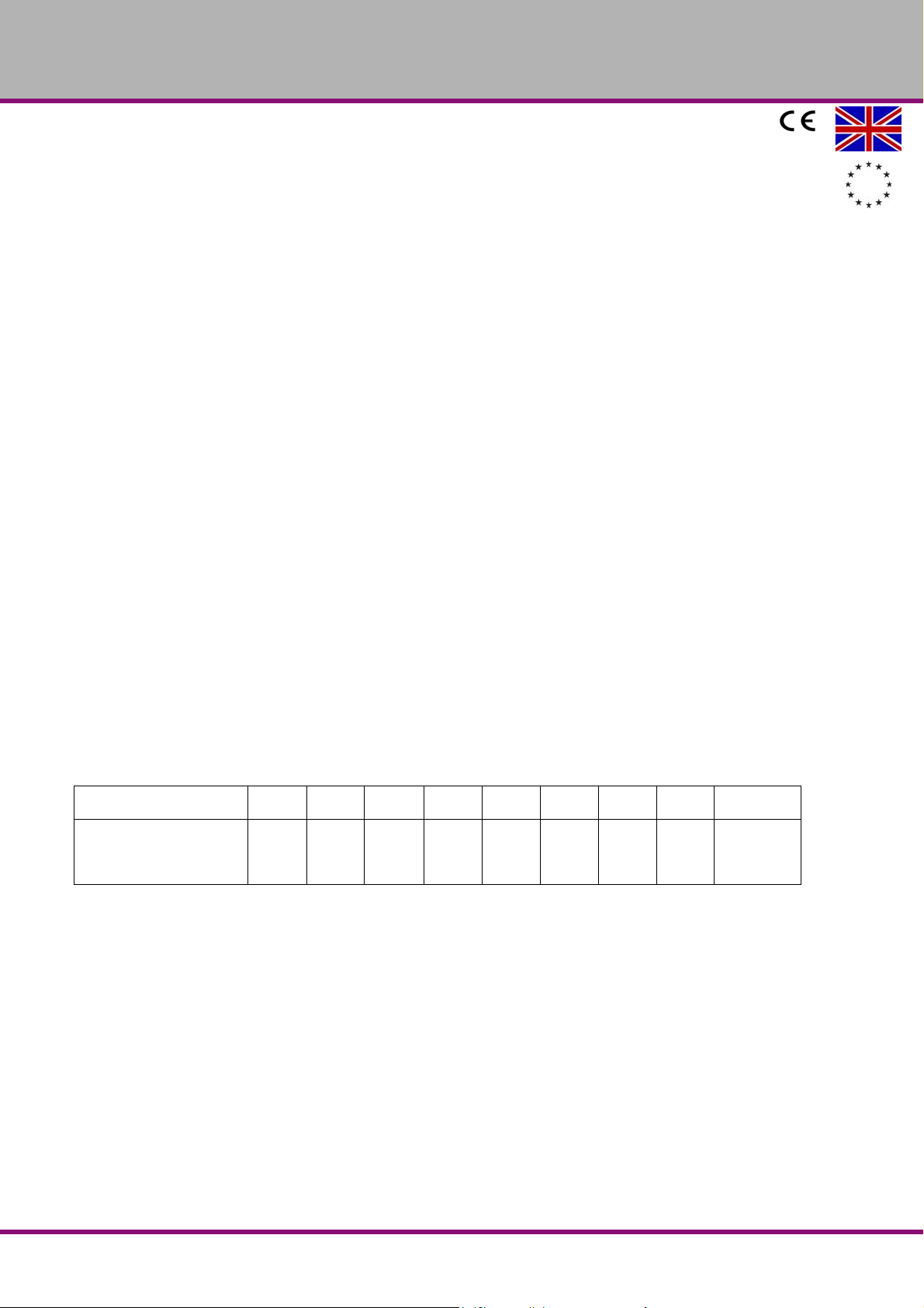
Meanings of the 9-pin D-type socket:
Pin No. 1 2 3 4 5 6 7 8 9
Differential TTL
Square Wave
A+ A- +5V 0V B+ B- Z+ Z- Shielding
Signals
DRO 3GB
EC - Declaration of Conformity
Version 1.0.1 2014-05-06 31 Original operating instructions
Page 16

OPTIMUM
MASCHINEN - GERMANY
3 Troubleshooting DRO 3
Failures Failure causes Troubleshooting
The digital display
does not display
anything
The cover is
charged.
One position dis-
play axis does not
count
1 Make sure that the power cable is
well connected.
2 Make sure that the power switch is
on.
3 Make sure that the voltage is suitable.
4 Short circuit inside the reading
device.
5 Make sure that the fuse is working.
1 Make sure that the machine tool and
the position display cover are well
grounded.
2 Make sure that the 230V power supply is available
1 Check if the position display still does
not count after you have exchanged the
reading device with the other axis.
2 The position display is in a deviating
function range.
1 Make sure that the power cable is well connected. Then switch on the power supply.
2 Switch on the power switch.
3 The voltage should be 230V +/ - 10 %.
4 Pull out the plug of the reading device.
5 Check and replace the fuse if necessary.
1 The machine tool and the position display
cover must be well grounded.
2 Check the 230V +/- 10 % power supply.
1 If the position display counts normally, it
may be a failure of the reading device, otherwise, it is is a failure of the position display.
2 Leave the deviation function range.
DRO 3GB
Version 1.0.1 dated 2014-05-06Page 32 Original operating instructions
Troubleshooting DRO 3
Page 17

OPTIMUM
MASCHINEN - GERMANY
4Annex
4.1 Copyright
This document is copyright. All derived rights are also reserved, especially those of translation,
re-printing, use of figu res, broadcast, reproduction by photo-mechanical or similar means and
recording in data processing systems, neither partial nor total.
Subject to technical changes without notice.
4.2 Liability claims for defects / warranty
Beside the legal liability claims for defects of the customer towards the seller, the manufacturer
of the product, OPTIMUM GmbH, Robert-Pfleger-Straße 26, D-96103 Hallstadt, does not grant
any further warranties unless they are liste d below or have been promised in the framework of
an individual contractual agreement.
The processing of the liability claims or of the warranty is performed as chosen by
OPTIMUM GmbH either directly or through one of its dealers.
Any defective products or components of such products will either be repaired or
replaced by components which are free from defects. The property of replaced products or components passes on to OPTIMUM GmbH.
The automatically generated original proof of purchase which shows the date of purchase,
the type of machine and the serial number, if applicable, is the precondition in order to
assert liability or warranty claims. If the original proof of purchase is not presented, we are
not able to perform any services.
Defects resulting from the following circumstances are excluded from liability and warranty
claims:
- Using the product beyond the technical options and proper use, in particular due to overstraining of the machine.
- Any defects arising by one's own fault due to faulty operations or if the operating manual
is disregarded
- Inattentive or incorrect handling and use of improper equipment
- Non-authorised modifications and repairs
- Insufficient installation and safeguarding of the machine
- Disregarding the installation requirements and conditions of use
- Atmospheric discharges, overvoltage and lightning strokes as well as chemical influences
The following items are as well not subject to the liability or warranty claims:
- Wearing parts and components which are subject to a standard wear as intended such
as e.g. V-belts, ball bearings, illuminants, filters, sealings, etc.
- Non reproducible software errors
Any services which OPTIMUM GmbH or one of its servants performs in order to fulfil in the
frame of an additional guarantee are neither an acceptance of the defects nor an acceptance of its obligation to compensate. Such services do neither delay nor interrupt the warranty period.
Place of jurisdiction among traders is Bamberg.
If one of the above mentioned agreements is totally or partially inefficient and/or null, it is
considered as agreed what is closest to the will of the warrantor and which remains in the
framework of the limits of liability and warranty which are predefined by this contract.
Annex
Version 1.0.1 dated 2014-05-06 Page 33Original operating instructions
DRO 3 GB
Page 18
OPTIMUM
MASCHINEN - GERMANY
4.3 Change information manual
Chapter Short note new version no.
3.5.2 Function diameter - radius added 1.0.1
3.5.3 Summing function of axes added 1.0.1
4.4 Advice for disposal / Options of re-use
Please dispose of your machine in an environmentally friendly way, not by disposing of the
waste not in the environment, but by acting in a professional way.
Please do not throw away the packaging and the used machine later on, but dispose of your
material according to the guidelines established by your municipality or by the responsible
waste management company.
4.4.1 Disposal of electrical and electronic components
Please make sure that the electrical components are disposed of professionally and according
to the legal regulations.
The machine is composed of electrical and electronic components and must not be disposed of
as household waste. According to the European directive 2002/96/EC regarding electrical and
electronic used devices and the implementation of national legislation used power tools and
electrical machines need to be collected separately and supplied to an environmentally friendly
recycling centre.
Being the machine operator, you should gather information regarding the authorised collection
or disposal system which applies for your company.
Please make sure that batteries and/or accumulators are disposed of in a professional way and
according to the legal regulations. Please throw empty accumulators only into the collection
boxes of retail markets or municipal waste disposal companies.
4.5 Disposal via municipal collecting points
Disposal of used electrical and electro nic com pone n ts
Disposal of used electric and electronic devices (Applicable in the countries of the European
Union and other European countries with a separate collecting system for such devices).
The sign on the product or on its packing indicates that the product must not be handled as
common household waist, but that it needs to be delivered to a central collection point for
recycling. Your contribution to the correct disposal of this product will protect the environment
and the health of your fellow men. The environment and the health are endangered by incorrect
disposal. Recycling of material will help to reduce the consumption of raw materials. Your District Office, the municipal waste collection station or the shop where you have bought the product will inform you about the recycling of this product.
4.6 RoHS, 2002/95/EC
The sign on the product or on its packaging indicates that this product complies with the European guideline 2002/95/EC.
DRO 3GB
Version 1.0.1 dated 2014-05-06Page 34 Original operating instructions
Annex
Page 19

EC - Declaration of Conformity
Hallstadt, 2014-05-06
Kilian Stürmer
(General manager)
OPTIMUM
MASCHINEN - GERMANY
The manufacturer /
retailer:
hereby declares that the following product,
Name: Digital position display
Designation DRO 3
Year of construction: 20__
EU directives:
2014/30/EC EMC Directive
2006/95/EG Low Voltage Directive
meets the provisions of the aforementioned directives, including any amendments
valid at the time of this statement.
Person responsible for the document: Kilian Stürmer, Phone: +49 (0) 951 96555-800
Address: Dr.-Robert- P fleger-Str. 26
Optimum Maschinen Germany GmbH
Dr.-Robert-Pfleger-Str. 26
D-96103 Hallstadt
D - 96103 Hallstadt
EC - Declaration of Conformity
Version 1.0.1 2014-05-06 35Original operating instructions
DRO 3 GB
 Loading...