


OPTI™ CCA-TS2 Analyzer
Operator’s Manual

OPERATOR’S MANUAL REVISION LOG
(Please record any changes made to this manual)
Revision |
Release Date |
Approved by |
Description |
A |
March 2013 |
|
per PCR120183 |
B |
July 2013 |
|
per PCR130109 |
C |
August 2013 |
|
per PCR130137 |
|
|
|
|
|
|
|
|
|
|
|
|
|
|
|
|
|
|
|
|
|
|
|
|
|
|
|
|
|
|
|
|
Proprietary Rights Notice
Information in this document is subject to change without notice. Companies, names and data used in examples are fictitious unless otherwise noted. No part of this document may be reproduced or transmitted in any form or by any means, electronic, mechanical or otherwise, for any purpose, without the express written permission of OPTI Medical Systems, Inc. OPTI Medical Systems, Inc. may have patents or pending patent applications,
trademarks, copyrights or other intellectual or industrial property rights covering this document or subject matter in this document. The furnishing of this document does not give a license to these property rights except as expressly provided in any written license agreement from OPTI Medical Systems.
© 2013 OPTI Medical Systems, Inc. All rights reserved.
OPTI, the OPTI Medical logo, and ComfortSampler are trademarks or registered trademarks of OPTI Medical Systems, Inc. in the United States and/or other countries. Other trademarks are the property of their respective owners.
Made in U.S.A.
OPTI Medical Systems, Inc. 235 Hembree Park Drive Roswell, GA 30076 USA www.optimedical.com
PD7301 REV C

Important Information! Important Information!
This Operator´s Manual contains important warnings and safety information to be observed by the user.
This instrument is only intended for one area of application which is described in the instructions. The most important prerequisites for application, operation and safety are explained to ensure smooth operation. No warranty or liability claims will be covered if the instrument is applied in areas other than those described or if the necessary prerequisites and safety measures are not observed.
The instrument is only to be operated by qualified personnel capable of observing these prerequisites.
Only accessories and supplies either delivered by or approved by OPTI Medical Systems are to be used with the instrument.
Due to this instrument’s operating principle, analytical accuracy not only depends on correct operation and function, but also upon a variety of external influences beyond the manufacturer’s control. Therefore, the test results from this instrument must be carefully examined by an expert, before further measures are taken based on the analytical results.
Treatment should never be administered based on results that are flagged on the printout.
Instrument adjustment and maintenance with removed covers and connected power mains are to be performed only by a qualified technician who is aware of the dangers involved.
Instrument repairs are to be performed only by the manufacturer or qualified service personnel.
Important Information! Important Information!

Operating Safety Information
•Overvoltage Category II when connected to a branch circuit.
•This equipment has been tested and found to comply with the limits for a Class B digital device, pursuant to Part 15 of the FCC Rules.
Caution:
•The instrument is designed as a conventional device (closed, not waterproof type).
•Do not operate the instrument in an explosive environment or in the vicinity of explosive anesthetic mixtures containing oxygen or nitrous oxide.
•This instrument is suitable for continuous operation.
•The power plug is to be plugged into a ground socket only. When using an extension cord, make sure that it is of the proper size and is properly grounded.
•Any breakage of the ground lead inside or outside the instrument or a loose ground connection can cause a hazardous condition when operating the instrument. Intentional disconnection of the grounding is not permitted.
•When replacing the fuses, make sure that they are of the same type and rating as the original fuses. Never use repaired fuses or short-circuit the fuse holders.
This device is a Class 1 Laser product according to the requirements of IEC 60825-1.
The LEDs have been certified as an EXEMPT RISK GROUP in compliance with IEC 62471. The maximum energy output is as follows:
670 nm (LED): 40 Microwatts max. for 400ms
780 nm (Laser): 40 Microwatts max. for 400ms
850 nm (Laser): 40 Microwatts max. for 400ms
Caution: Use of controls or adjustments or performance of procedures other than those specified herein may result in hazardous radiation exposure.
Conditions of Acceptability:
Coin cell battery on main board:
•Overcharging, short circuiting, reverse charging, mutilation or incineration of the cells must be avoided to prevent one or more of the following occurrences: release of toxic materials, release of hydrogen and/or oxygen gas, rise in surface temperature.
•If a cell has leaked or vented, it should be replaced immediately using protective gloves.
•If and when necessary, these cells must be replaced with identical new ones from the same manufacturer. If a cell to be replaced is connected with other cells in series, it is recommended that the other cells be replaced with new ones at the same time.
•Reverse polarity installation of the cell in the end product must be avoided.
Operating Safety Information

Operating Safety Information
Recommendations for Usage and Storage of Lithium Ion Battery Pack:
a)Do not dismantle, open or shred secondary cells or batteries.
b)Do not expose cells or batteries to heat or fire. Avoid storage in direct sunlight.
c)Do not short-circuit a cell or a battery. Do not store cells or batteries haphazardly in a box or drawer where they may short-circuit each other or be short-circuited by other metal objects.
d)Do not remove a cell or battery from its original packaging until required for use.
e)Do not subject cells or batteries to mechanical shock.
f)In the event of cell leaking, do not allow the liquid to come in contact with skin or eyes.
If contact has been made, wash the affected area with copious amounts of water and seek medical advice.
g)Do not use any charger other than that specifically provided for use with the equipment.
h)Observe the plus (+) and minus (-) marks on the cell, battery and equipment and ensure correct use.
i)Do not use any cell or battery which is not designed for use with the equipment.
j)Do not mix cells of different manufacture, capacity, size or type within a device.
k)Keep cells and batteries out of reach of children.
l)Seek medical advice immediately if a cell or a battery has been swallowed.
m)Always purchase the correct cell or battery for the equipment.
n)Keep cells and batteries clean and dry.
o)Wipe the cell or battery terminals with a clean dry cloth if they become dirty.
p)Secondary cells and batteries need to be charged before use. Always use the correct charger and refer to the manufacturer’s instructions or equipment manual for proper charging instructions.
q)Do not leave a battery on prolonged charge when not in use.
r)After extended periods of storage, it may be necessary to charge and discharge the cells or batteries several times to obtain maximum performance.
s)Secondary cells and batteries give their best performance when they are operated at normal room temperature (20 °C ± 5 °C).
t)Retain the original product literature for future reference.
u)Use cell and battery only in the application for which it was intended.
v)When possible, remove the battery from the equipment when not in use.
w)Dispose of cells and batteries properly.
Operating Safety Information

Symbol Definitions
The symbols described below are used on the packaging of OPTI™ CCA-TS2 related products.
Symbol Explanation
EXP
LOT
Attention Symbol – Refer to the Operator’s Manual or Service Manual for further instructions. This symbol is located on the inside of the instruments and product packaging.
Expiration / Use By Symbol – Product to be used by the expiration date indicated to the right of this symbol. This symbol is located on all consumables, which are controlled via an expiration or use by date.
Batch Code Symbol – Manufacturing lot number is located to the right of this symbol. This symbol is located on all products, which are controlled via a lot number.
Do Not Re-use Symbol – Identifies products which are not to be used for more than the specified period of time as defined in the product instructions. This symbol is located on all applicable product packaging.
Recycle Plastic Symbol - Identifies the clear plastic material (polyethylene terephthalate glycol) used in the packaging of the product. Containers identified with this symbol can be considered recyclable. This symbol is located on all applicable product packaging.
WEEE-Symbol - This product complies with WEEE Directive 2002/96/EC which mandates the treatment, recovery and recycling of electric and electronic equipment.

Symbol
 C
C
 C
C  F
F
 F
F
REF
EC REP
Explanation
Biohazard Symbol – Products and/or components containing this symbol should be handled as biohazardous material after use.
Temperature Limit Symbol – Products and/or components which contain this symbol must be stored within the specified temperature range.
For in-vitro diagnostic use
This product fulfils the requirements of Directive 98/79/EC on in-vitro diagnostic medical devices.
Catalog number
Please read pack insert. / Follow the instrument’s instructions for use!
Manufactured by
Authorized European Community Representative

PREFACE
PREFACE
Welcome
Your OPTI™ CCA-TS2 Analyzer is a powerful tool designed to help you quickly, accurately and efficiently conduct basic testing of hydrogen ion concentration (pH), carbon dioxide partial pressure (PCO2), oxygen partial pressure (PO2), sodium (Na+), potassium (K+), ionized calcium (Ca++), chloride (Cl-), glucose (Glu), blood urea nitrogen (BUN), lactate (Lac), total hemoglobin concentration (tHb) and hemoglobin oxygen saturation (SO2), depending on the cassette configuration, in the convenience of your own laboratory.
This manual will help guide you through setting up your analyzer and will help you start analyzing samples. As you become familiar with the operation of the unit, you should use the manual as a reference for day-to-day routines and as a guide for maintenance and troubleshooting.
How to use this manual
If you have an analyzer that is not yet set up, you should begin by reading Chapters 1 and 2. For programming and quality control functions, read Chapters 3 and 4.
Information on analyzer operation and data management is contained in Chapters 5 and 6. Detailed maintenance and service information can be found in Chapters 7 and 8. Operating principles are described in Chapter 9.

|
|
|
|
TABLE OF CONTENTS |
|
|
|
|
|||
TABLE OF CONTENTS |
|
|
|||
PREFACE................................................................................................... |
|
IX |
|||
Welcome......................................................................................................................... |
|
IX |
|||
How to use this manual................................................................................................. |
IX |
||||
1 |
INTRODUCTION................................................................................... |
1-1 |
|||
1.1 |
|
Intended Use...................................................................................................... |
1-1 |
||
1.2 |
|
Principles of Operation..................................................................................... |
1-1 |
||
1.3 |
|
Contents............................................................................................................. |
1-2 |
||
1.4 |
|
Analyzer Components...................................................................................... |
1-3 |
||
1.5 |
|
Consumables..................................................................................................... |
1-8 |
||
2 |
SETUP................................................................................................... |
|
2-1 |
||
2.1 |
|
Important Safety Instructions.......................................................................... |
2-1 |
||
2.2 |
|
Choosing a Location......................................................................................... |
2-1 |
||
2.3 |
|
Setting up the OPTI CCA-TS2 Analyzer........................................................... |
2-2 |
||
3 |
CUSTOMIZATION................................................................................. |
3-1 |
|||
3.1 |
|
Setting Time and Date....................................................................................... |
3-1 |
||
3.2 |
|
Setup.................................................................................................................. |
|
3-2 |
|
3.2.1 |
QC Setup........................................................................................................................ |
3-3 |
|||
|
|
3.2.1.1 |
Setting up the Quality Control Material............................................................................ |
3-3 |
|
|
|
3.2.1.2 |
Selecting QC Lockout...................................................................................................... |
3-5 |
|
3.2.2 |
Customizing Patient Information.................................................................................... |
3-8 |
|||
|
|
3.2.2.1 |
Setting up Patient Information.......................................................................................... |
3-8 |
|
|
|
3.2.2.2 Suppressing Results for Measured Parameters............................................................ |
3-11 |
||
|
|
3.2.2.3 |
Setting up Calculated Parameters................................................................................. |
3-12 |
|
|
|
3.2.2.4 |
Setting up Limits for Measurement Parameters ............................................................ |
3-13 |
|
|
|
3.2.2.5 |
Setting up Limits for Calculated Parameters ................................................................. |
3-15 |
|
|
|
3.2.2.6 |
Setting up Test Panels .................................................................................................. |
3-17 |
|
|
|
3.2.2.7 |
Setting up Correlation Factors....................................................................................... |
3-19 |
|
3.2.3 |
Setting up Security....................................................................................................... |
3-20 |
|||
|
|
3.2.3.1 |
Selecting Security Settings............................................................................................ |
3-20 |
|
|
|
3.2.3.2 |
Setting up a Password................................................................................................... |
3-26 |
|
|
|
3.2.3.3 |
System Reinitialization................................................................................................... |
3-27 |
|
Operator’s Manual – OPTI CCA-TS2 |
I |

TABLE OF CONTENTS
3.2.4 |
Miscellaneous System Settings.................................................................................... |
3-28 |
|
|
3.2.4.1 |
Setting the Printer.......................................................................................................... |
3-28 |
|
3.2.4.2 |
Defining Units................................................................................................................. |
3-29 |
|
3.2.4.3 |
Selecting a Language.................................................................................................... |
3-31 |
|
3.2.4.4 |
Hardware Settings.......................................................................................................... |
3-32 |
|
3.2.4.5 |
Setting up Communications........................................................................................... |
3-35 |
|
3.2.4.6 |
Configuring Ethernet Settings........................................................................................ |
3-38 |
3.2.5 |
Maintenance Setup...................................................................................................... |
3-40 |
|
4 CALIBRATION AND QUALITY CONTROL.......................................... |
4-1 |
|
4.1 |
Calibration.......................................................................................................... |
4-1 |
4.2 |
QC Overview...................................................................................................... |
4-2 |
4.3 |
Proficiency Testing........................................................................................... |
4-2 |
4.4 |
Calibration Verification..................................................................................... |
4-3 |
4.5 |
QC Recommendations...................................................................................... |
4-3 |
4.5.1 |
Running an SRC Measurement..................................................................................... |
4-4 |
4.5.2 |
Running a QC Sample................................................................................................... |
4-8 |
|
4.5.2.1 Running Controls (OPTI CHECK, OPTI CHECK PLUS).................................................. |
4-8 |
5 SAMPLE HANDLING AND PATIENT TESTING.................................. |
5-1 |
|
5.1 |
Specimen Collection and Handling................................................................. |
5-1 |
5.1.1 |
Safety............................................................................................................................. |
5-1 |
5.1.2 |
Sample Requirements.................................................................................................... |
5-1 |
5.1.3 |
Anticoagulants and Sample Collection Devices............................................................. |
5-1 |
5.1.4 |
Syringes......................................................................................................................... |
5-2 |
5.1.5 |
Capillary Tubes............................................................................................................... |
5-2 |
5.1.6 |
OPTI Medical ComfortSamplers™................................................................................. |
5-2 |
5.1.7 |
Handling and Storage of Samples.................................................................................. |
5-3 |
5.1.8 |
Test Conditions............................................................................................................... |
5-4 |
5.2 |
Sample Preparation........................................................................................... |
5-4 |
5.2.1 |
Whole Blood Samples.................................................................................................... |
5-4 |
5.3 |
Running A Patient Sample................................................................................ |
5-5 |
6 DATA MANAGEMENT ......................................................................... |
6-1 |
|
6.1 |
Printing Measurement and Statistics Reports................................................ |
6-1 |
6.1.1 |
Patient Measurement Reports........................................................................................ |
6-1 |
6.1.2 |
SRC Measurement Reports........................................................................................... |
6-3 |
6.1.3 |
SRC Statistics Reports................................................................................................... |
6-4 |
6.1.4 |
Control Measurement Reports....................................................................................... |
6-5 |
6.1.5 |
Control Statistics Reports............................................................................................... |
6-6 |
II |
Operator’s Manual – OPTI CCA-TS2 |
|
|
|
TABLE OF CONTENTS |
|
|
|
|
6.2 |
|
Printing Diagnostics Reports........................................................................... |
6-7 |
6.2.1 |
Patient Diagnostics Reports........................................................................................... |
6-7 |
|
6.2.2 |
SRC Diagnostics Reports............................................................................................... |
6-8 |
|
6.2.3 |
Controls Diagnostics Reports......................................................................................... |
6-9 |
|
6.2.4 |
Error Report.................................................................................................................. |
6-10 |
|
6.3 |
|
Miscellaneous Reports................................................................................... |
6-11 |
6.3.1 |
Maintenance Report...................................................................................................... |
6-11 |
|
6.4 |
|
Importing/Exporting Data............................................................................... |
6-12 |
6.4.1 |
Exporting Measurement Data....................................................................................... |
6-12 |
|
6.4.2 |
Exporting Configuration Data....................................................................................... |
6-14 |
|
6.4.3 |
Exporting the Database................................................................................................ |
6-15 |
|
7 |
MAINTENANCE ................................................................................... |
7-1 |
|
7.1 |
|
Daily Maintenance............................................................................................. |
7-1 |
7.2 |
|
Weekly Maintenance......................................................................................... |
7-1 |
7.3 |
|
Quarterly Maintenance – Performing tHb Calibration.................................... |
7-2 |
7.4 |
|
Annual Maintenance......................................................................................... |
7-6 |
7.4.1 |
Replacing Peri Pump Cartridge...................................................................................... |
7-6 |
|
7.4.2 |
Replacing Gas I/O Port.................................................................................................. |
7-8 |
|
7.5 |
|
As Needed Maintenance................................................................................... |
7-9 |
7.5.1 |
Changing the Gas Bottle................................................................................................ |
7-9 |
|
7.5.2 |
Changing the Printer Paper........................................................................................... |
7-11 |
|
7.5.3 |
Performing Routine Cleaning........................................................................................ |
7-11 |
|
8 |
DIAGNOSTICS AND TROUBLESHOOTING....................................... |
8-1 |
|
8.1 |
|
System Error and Warning Messages............................................................. |
8-1 |
8.1.1 |
System Warning Messages............................................................................................ |
8-2 |
|
8.1.2 |
System Error Messages................................................................................................. |
8-6 |
|
8.1.3 |
System Stop Messages................................................................................................ |
8-12 |
|
8.1.4 |
Not Ready Messages................................................................................................... |
8-13 |
|
8.1.5 |
Fatal Error Messages................................................................................................... |
8-16 |
|
8.2 |
|
Diagnostics...................................................................................................... |
8-18 |
8.2.1 |
Checking Versions........................................................................................................ |
8-18 |
|
8.2.2 |
Checking System Temperatures.................................................................................. |
8-19 |
|
8.2.3 |
Checking Gas Pressure............................................................................................... |
8-19 |
|
8.2.4 |
Checking the LEDs....................................................................................................... |
8-20 |
|
8.2.5 |
Verifying Barometric Pressure...................................................................................... |
8-20 |
|
8.2.6 |
Checking the Battery Voltage....................................................................................... |
8-21 |
|
8.2.7 |
Checking the Cooling Fan............................................................................................ |
8-21 |
|
Operator’s Manual – OPTI CCA-TS2 |
III |

TABLE OF CONTENTS
8.2.8 |
Checking the Gas Valve............................................................................................... |
8-22 |
8.2.9 |
Checking the Valve Drive............................................................................................. |
8-22 |
8.2.10 |
Checking the Factory Settings (FSet).......................................................................... |
8-23 |
8.2.11 |
Checking the Bar Code Scanner.................................................................................. |
8-23 |
8.2.12 |
Checking the Printer..................................................................................................... |
8-24 |
8.2.13 |
Checking the Optics .................................................................................................... |
8-25 |
8.2.14 |
Checking the Ethernet Interface................................................................................... |
8-26 |
8.2.15 |
Checking the Pump Flow............................................................................................. |
8-27 |
8.2.16 |
Checking the Pump Motor............................................................................................ |
8-28 |
8.2.17 |
Checking the Display.................................................................................................... |
8-28 |
8.2.18 |
Checking the Touch Screen......................................................................................... |
8-29 |
8.2.19 |
Gas Test....................................................................................................................... |
8-30 |
8.2.20 |
Setting up the B-Lac Cassette ..................................................................................... |
8-31 |
8.2.21 |
Cassette Detect............................................................................................................ |
8-33 |
8.3 |
Troubleshooting.............................................................................................. |
8-34 |
8.3.1 |
Troubleshooting Procedure for tHb/SO2....................................................................... |
8-34 |
8.3.2 |
Troubleshooting Procedure for Bar Code Scanner...................................................... |
8-35 |
9 OPERATING PRINCIPLES................................................................... |
9-1 |
|
9.1 |
Intended Use...................................................................................................... |
9-1 |
9.2 |
Principles of Procedure.................................................................................... |
9-1 |
9.3 |
Operation........................................................................................................... |
9-2 |
9.4 |
Specimen Collection and Handling................................................................. |
9-3 |
9.4.1 |
Safety............................................................................................................................. |
9-3 |
9.4.2 |
Sample Requirements.................................................................................................... |
9-3 |
9.4.3 |
Anticoagulants and Sample Collection Devices............................................................. |
9-3 |
9.4.4 |
Syringes......................................................................................................................... |
9-3 |
9.4.5 |
Capillary Tubes............................................................................................................... |
9-3 |
9.4.6 |
OPTI Medical ComfortSamplers™................................................................................. |
9-4 |
9.4.7 |
Handling and Storage of Samples.................................................................................. |
9-4 |
9.5 |
Procedure........................................................................................................... |
9-5 |
9.5.1 |
Materials Needed........................................................................................................... |
9-5 |
9.5.2 |
Test Conditions............................................................................................................... |
9-6 |
9.5.3 |
Input Values.................................................................................................................... |
9-6 |
9.5.4 |
Calculated Values........................................................................................................... |
9-9 |
9.5.5 |
Calibration...................................................................................................................... |
9-9 |
9.5.6 |
Quality Control.............................................................................................................. |
9-10 |
9.5.7 |
Reference Intervals ...................................................................................................... |
9-11 |
9.5.8 |
Specific Performance Characteristics........................................................................... |
9-11 |
9.5.9 |
Limitations.................................................................................................................... |
9-12 |
9.5.10 |
Interferences ............................................................................................................... |
9-13 |
9.5.11 |
Accessories.................................................................................................................. |
9-14 |
IV |
Operator’s Manual – OPTI CCA-TS2 |

TABLE OF CONTENTS
10SUPPLIES........................................................................................... |
10-1 |
|
10.1 |
Analyzer........................................................................................................... |
10-1 |
10.2 |
Cassettes......................................................................................................... |
10-1 |
10.3 |
Controls/Calibrators........................................................................................ |
10-1 |
10.4 |
Consumable Items.......................................................................................... |
10-2 |
10.5 |
Accessories..................................................................................................... |
10-2 |
10.6 |
Manuals............................................................................................................ |
10-2 |
10.7 |
Spare Parts...................................................................................................... |
10-3 |
10.8 |
Technical Assistance...................................................................................... |
10-3 |
10.9 |
Warranty Registration (U.S. Market Only)..................................................... |
10-4 |
ANALYTES
pH ......................................................................................................................... |
pH-1 |
pH (Dry Sensor - B-Lac Cassette)........................................................................ |
pH-B-1 |
PCO2 .................................................................................................................... |
PCO2-1 |
PCO2 (Dry Sensor - B-Lac Cassette).............................................................. |
PCO2-B-1 |
PO2 ....................................................................................................................... |
PO2-1 |
PO2 (Dry Sensor - B-Lac Cassette).................................................................... |
PO2-B-1 |
Sodium (Na+).............................................................................................................. |
Na-1 |
Potassium (K+)............................................................................................................. |
K-1 |
Ionized Calcium (Ca++).............................................................................................. |
Ca-1 |
Chloride (Cl-)............................................................................................................... |
Cl-1 |
Glucose (Glu)............................................................................................................ |
Glu-1 |
BUN (Urea).............................................................................................................. |
BUN-1 |
Lactate (B-Lac Cassette)......................................................................................... |
Lac-1 |
Total Hemoglobin Concentration (ctHb) and |
|
Hemoglobin Oxygen Saturation (SO2%)...................................................... |
THB/SO2-1 |
Operator’s Manual – OPTI CCA-TS2 |
V |

TABLE OF CONTENTS
APPENDIX A - TECHNICAL SPECIFICATIONS...................................... |
A-1 |
Measurement Range.................................................................................................................. |
A-1 |
Barometric Pressure.................................................................................................................. |
A-1 |
Operating Altitude....................................................................................................................... |
A-1 |
Pollution Degree......................................................................................................................... |
A-1 |
Operating Parameters................................................................................................................ |
A-2 |
Input Values............................................................................................................................... |
A-2 |
Temperature Corrected Values.................................................................................................. |
A-4 |
Reference Ranges..................................................................................................................... |
A-5 |
Data Management...................................................................................................................... |
A-6 |
Mains Supply for External Power Supply................................................................................... |
A-6 |
DC Supply for Instrument........................................................................................................... |
A-6 |
Overvoltage Category................................................................................................................ |
A-6 |
Dimensions and Weight............................................................................................................. |
A-6 |
Classifications............................................................................................................................ |
A-7 |
Calculated Parameters............................................................................................................... |
A-7 |
Temperature............................................................................................................................... |
A-7 |
Units Used in Measured and Input Parameters for Calculations............................................... |
A-7 |
Conversion Table for Units......................................................................................................... |
A-8 |
Equations................................................................................................................................... |
A-8 |
APPENDIX B - MENU STRUCTURE....................................................... |
B-1 |
APPENDIX C - MAINTENANCE LOG...................................................... |
C-1 |
APPENDIX D - REPORT FORMATS....................................................... |
D-1 |
Basic Patient Report ................................................................................................................. |
D-1 |
SRC Measurement Report ........................................................................................................ |
D-2 |
SRC Statistics Report ............................................................................................................... |
D-3 |
Controls Measurement Report................................................................................................... |
D-4 |
Controls Statistics Report .......................................................................................................... |
D-5 |
Maintenance Report................................................................................................................... |
D-6 |
Error Report............................................................................................................................... |
D-7 |
B-Lac Setup Report.................................................................................................................... |
D-8 |
INDEX......................................................................................................... |
I-1 |
VI |
Operator’s Manual – OPTI CCA-TS2 |

1 INTRODUCTION
1 |
INTRODUCTION.................................................................................. |
1-1 |
1.1 |
Intended Use...................................................................................................... |
1-1 |
1.2 |
Principles of Operation..................................................................................... |
1-1 |
1.3 |
Contents............................................................................................................. |
1-2 |
1.4 |
Analyzer Components...................................................................................... |
1-3 |
1.5 |
Consumables..................................................................................................... |
1-8 |
Operator’s Manual – OPTI CCA-TS2 |
1-i |

1 INTRODUCTION
1INTRODUCTION
1.1Intended Use
The OPTI™ CCA-TS2 Critical Care Analyzer is intended to be used for the measurement of hydrogen ion concentration (pH), carbon dioxide partial pressure (PCO2), oxygen partial pressure (PO2), sodium (Na+), potassium (K+), ionized calcium (Ca++), chloride (Cl-), glucose (Glu), blood urea nitrogen (BUN/urea), lactate (Lac), total hemoglobin concentration (tHb) and hemoglobin oxygen saturation (SO2) in samples of whole blood, and pH, sodium, potassium, ionized calcium, chloride, glucose and BUN (urea) in serum and plasma, in either a traditional blood gas, clinical laboratory setting or point-of-care locations by personnel minimally qualified to perform and report these results.
The table below provides important information regarding supported sample types, available reporting units and analyzer measurement ranges for each parameter.
|
|
Sample Type |
|
Available Units |
Measurement |
Display |
||||
|
|
|
|
|
|
|
|
Range |
Resolution |
|
Parameter |
Whole |
|
Plasma |
|
Serum |
Default |
Other |
(Default Units) |
(Lo/Hi) |
|
|
blood |
|
|
|
|
|
|
|
|
|
pH |
x |
|
x |
|
x |
pH units |
|
6.6 - 7.8 |
0.01/0.001 |
|
PCO2 |
x |
|
|
|
|
mmHg |
kPa |
10 |
- 200 |
1/0.1 |
PO2 |
x |
|
|
|
|
mmHg |
kPa |
10 |
- 700 |
1/0.1 |
Na+ |
x |
|
x |
|
x |
mmol/L |
mg/dL |
100 - 180 |
1/0.1 |
|
K+ |
x |
|
x |
|
x |
mmol/L |
mg/dL |
0.8 |
- 9.99 |
0.1/0.01 |
Ca++ |
x |
|
x |
|
x |
mmol/L |
mg/dL |
0.2 - 3.0 |
0.01 |
|
Cl- |
x |
|
x |
|
x |
mmol/L |
mg/dL |
50 |
- 160 |
1/0.1 |
Glu |
x |
|
x |
|
x |
mg/dL |
mmol/L |
30-400 / 1.7-22 |
1/0.1 |
|
BUN/urea |
x |
|
x |
|
x |
mg/dL |
mmol/L |
2.8-112.0 / 1-40 |
0.1/0.01 |
|
Lac |
x |
|
|
|
|
mmol/L |
mg/dL |
0.3 |
- 17.5 |
0.01/0.01 |
tHb |
x |
|
|
|
|
g/dL |
mmol/L, g/L |
5 |
- 25 |
0.1 |
SO2 |
x |
|
|
|
|
% |
|
60 |
- 100 |
1/0.1 |
1.2Principles of Operation
The OPTI CCA-TS2 is a microprocessor-controlled medical instrument measuring optical fluorescence from discrete sensors called optical electrodes (optodes).
A disposable, single-use cassette contains all of the elements needed for calibration, sample measurement and waste containment. Specific calibration information from the cassette is scanned into the analyzer by holding the cassette package in front of the bar code scanner. The cassette is then placed into the measurement chamber.
The analyzer warms the cassette to 37.0 ± 0.1 °C (98.6 ± 0.1 °F), and performs a calibration verification on the sensors for PCO2 and PO2 by passing a precision calibration gas mixture across the optode sensors. The pH and electrolyte channels are calibrated with precision buffer solution contained in the cassette. The tHb and SO2 channels are factory-calibrated.
Operator’s Manual – OPTI CCA-TS2 |
1-1 |

1 INTRODUCTION
When calibration is verified, the analyzer aspirates the blood sample into the cassette and across the optode sensors. Fluorescence emission is then measured after equilibrating with the blood sample. After a single measurement, the cassette, containing the blood sample, is removed from the analyzer and discarded. The analyzer contains no reagents, blood or waste.
1.3Contents
Before you begin installing your OPTI CCA-TS2 Analyzer, take a moment to look over the contents to ensure you have the following:
•Power supply with power cord
•Battery
•1 Multi-level Standard Reference Cassette (SRC) (Levels 1, 2 and 3)
•Thermal printer paper
•tHB calibration cassette
You will also need the following consumables prior to setup:
•OPTI sensor cassettes
•Gas bottle
•Quality Control Material - OPTI CHECK or OPTI CHECK PLUS (with glucose or BUN cassettes)
1-2 |
Operator’s Manual – OPTI CCA-TS2 |

1 INTRODUCTION
1.4Analyzer Components
Before setting up the OPTI CCA-TS2 Analyzer, it is important to familiarize yourself with the analyzer’s components:
Printer
Printer Release |
Stylus |
|
|
Button |
Touch Screen |
|
|
|
Display |
Sample Measurement
Chamber (SMC)
 Status Light
SMC Latch
Gas Bottle
Bar Code Scanner
Power Connector
Battery
On/Off Button
Handle/Tilt Stand
Fig. 1-1 OPTI CCA-TS2 Major Components
Operator’s Manual – OPTI CCA-TS2 |
1-3 |
1 INTRODUCTION
Touch Screen
Fig. 1-2 Touch Screen
Status Light
Fig. 1-3 Status Light
Sample Measurement Chamber (SMC)
Fig. 1-4 Open SMC Cover
The analyzer activities are communicated to you through a backlit Touch screen (Fig. 1-2), displaying the activities of the analyzer, sample results and other relevant information.
You communicate with the analyzer through a graphical user interface which is used to perform all
analyzer functions.
To the right of the display is a two-color status light (Fig. 1-3). During operation you will see one of the following:
•Green Light: The system is running a measurement and waiting for user action.
•Blinking Green Light: System is in process of calibration or measurement. Do not open the cover.
•Red Light: A red status light indicates an error that will terminate the process.
•Blinking Red Light: System has encountered a problem and needs operator interaction before it will proceed.
Inside the top of the unit is the Sample Measurement Chamber (SMC) for the OPTI Cassette. To open the cover, press down on the red SMC latch, and the cover will pop up (Fig. 1-4).
Several LEDs and two infrared lasers are located inside the sample measuring chamber.
1-4 |
Operator’s Manual – OPTI CCA-TS2 |

1 INTRODUCTION
Bar Code Scanner
The bar code scanner on the right side of the instrument reads lot, expiration information, and QC ranges if applicable from cassettes, controls, SRCs and gas bottles, as well as user-input bar codes for operator and patient IDs (Fig. 1-5).
Fig. 1-5 Bar Code Scanner
Thermal Printer
The thermal printer is accessed by pressing the red printer release button on the door (Fig. 1-6).
The printer uses heat-sensitive paper to print measured values, quality control values, calibration values, as well as patient and diagnostic information.
Fig. 1-6 Thermal Printer
Peristaltic Pump
Contained within the same compartment is a peristaltic pump cartridge which is used to transport liquids and gases (Fig. 1-7).
All liquids are contained within the OPTI Cassette and do not enter the instrument.
NOTE: The peristaltic pump cartridge is a replaceable item
(See Maintenance Section 7.4.1).
Fig. 1-7 Peristaltic Pump
Operator’s Manual – OPTI CCA-TS2 |
1-5 |
1 INTRODUCTION
Model and Serial Numbers
The model and serial number identifiers are located on an identification plate on the bottom panel of the unit (Fig. 1-8).
Fig. 1-8 Model and Serial Numbers
Back of Analyzer
USB Type B |
USB Type A |
Port |
Port |
Storage |
LED |
Ethernet |
Compartment |
Port |
Fig. 1-9 Back of the OPTI CCA-TS2
On the rear of the unit is (Fig. 1-9):
•An Ethernet port
•An LED which indicates the charging status of the battery.
•A USB Type A port to quickly upload software and download data using a standard USB mass storage device.
•A USB Type B port for connection to computer or external printer.
•A storage compartment that can hold an extra paper roll, the SRC, other supplies or accessories (Fig. 1-9).
Battery Pack
On the left side of the unit is the rechargeable battery pack. It is removed by squeezing the handle and sliding it out (Fig. 1-10). The battery allows you to operate the OPTI CCA-TS2 without having to plug the unit into an electrical outlet.
The battery is charged automatically whenever the analyzer’s external power supply is plugged into an electrical outlet.
Fig. 1-10 Battery Pack
1-6 |
Operator’s Manual – OPTI CCA-TS2 |

1 INTRODUCTION
Power Connector and Power Button
Next to the battery pack is the power connector where you can connect the OPTI CCA-TS2 to an external power supply (Fig. 1-11).
The power button is located on the left side of the unit next to the power connector (Fig. 1-11).
NOTE: To power down the system, hold the power button in for 2 seconds.
Fig. 1-11 Power Connector and Power Button
Carrying Handle
Fig. 1-12 Carrying Handle
Fig. 1-13 Pull down handle
Fig. 1-14 Tilt stand
The OPTI CCA-TS2 is equipped with a carrying handle for easy transport, which can also be used as a tilt stand to place the instrument at a convenient viewing angle for the user.
•To extend the handle to carrying position, place the analyzer on its back and position your fingers in the cutouts on each side of the handle. Push up until the handle is fully extended (Fig. 1-12).
•To use the handle as a tilt stand, pull down the handle (Fig. 1-13) and lock it in the lower position (Fig. 1-14). Turn analyzer back to original position (Fig. 1-15).
Fig. 1-15 Tilt stand
Operator’s Manual – OPTI CCA-TS2 |
1-7 |
1 INTRODUCTION
1.5Consumables
OPTI Sensor Cassette
The self-contained OPTI Sensor Cassette has an integral valve with a reservoir. The valve seals away the sample after measurement, allowing safe, clean sample disposal (Fig. 1-16).
Fig. 1-16 OPTI Sensor Cassette
Sample Fillport and
Syringe Adapter
Fig. 1-17 Sample Fillport and
Syringe Adapter
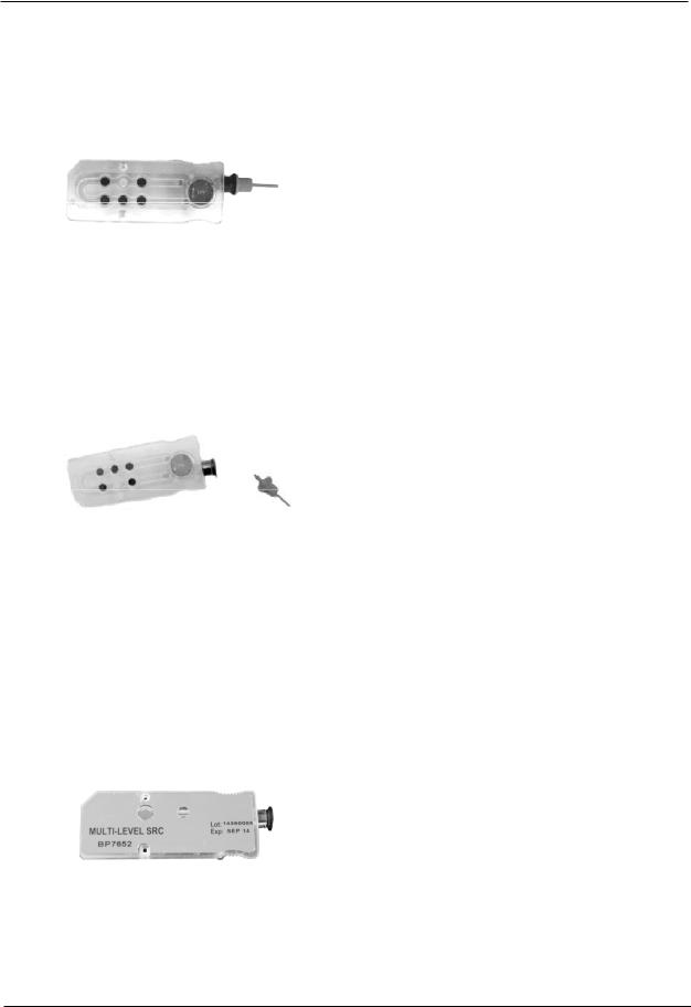
Standard Reference Cassette (SRC)
Fig. 1-18 Standard Reference Cassette
The sample fillport is contained in the OPTI Cassette and projects from the chamber for easy, automatic sampling. It includes a removable syringe adapter for sampling with a syringe.
For sampling with a capillary, simply remove the adapter (Fig. 1-17).
NOTE: The syringe adapter may be removed while the cassette is inside the SMC.
NOTE: DO NOT INJECT the sample. It will be aspirated automatically.
The Standard Reference Cassette (SRC)
(Fig. 1-18) is a reusable sensor cassette used for daily quality control testing. The multi-level SRC can be found in the storage compartment of your analyzer. Each new analyzer comes with one multilevel SRC that can test at 3 levels. The SRC should be kept in its pouch when not in use (see section 4.5 for instructions).
1-8 |
Operator’s Manual – OPTI CCA-TS2 |

1 INTRODUCTION
tHb Calibration Cassette
The reusable tHb Calibration Cassette (Fig. 1-19) is used for the quarterly calibration of the OPTI CCA-TS2 Analyzer (See Section 7.3 Quarterly Maintenance - Performing tHb Calibration).
Fig. 1-19 tHb Calibration Cassette
Gas Bottle
During calibration, the OPTI CCA-TS2 uses a precision gas which is completely self-contained in a disposable low-pressure bottle. The bottle is inserted on the right side of the unit after scanning the bar code (Fig. 1-20).
The TS2 will only work with gas bottles with a red base (BP7162).
Fig. 1-20 Gas Bottle
Congratulations!
You have just learned the basic components of the analyzer and are now ready to install your system.
Operator’s Manual – OPTI CCA-TS2 |
1-9 |

2 SETUP
2 |
SETUP ................................................................................................. |
2-1 |
2.1 |
Important Safety Instructions............................................................................... |
2-1 |
2.2 |
Choosing a Location............................................................................................. |
2-1 |
2.3 |
Setting up the OPTI CCA-TS2 Analyzer............................................................... |
2-2 |
Operator’s Manual – OPTI CCA-TS2 |
2-i |

2 SETUP
2SETUP
2.1 Important Safety Instructions
Before you begin installing your OPTI™ CCA-TS2 Analyzer, carefully read the overview information in this chapter.
For your own safety and the proper operation of your equipment, always follow these precautions when working with your OPTI CCA-TS2:
•Keep the analyzer away from all sources of liquids such as sinks and wash basins.
•Keep the analyzer away from explosive gases or vapors.
•Always handle blood samples and collection devices with care.
•Use approved protective gloves to avoid direct contact with sample.
•Dispose of OPTI Cassette according to local regulations.
2.2Choosing a Location
Location is important for trouble-free operation of your analyzer. Before you begin setup, choose a site that is convenient for your sampling needs and meets the following physical requirements of the unit:
•Grounded electrical outlet.
•Away from direct sunlight.
•Room temperature within 10 - 30º C (50 - 86° F).
•Maximum relative humidity of 95% (non-condensing).
•Ample room to allow air to circulate around the unit.
•Away from strong electromagnetic fields, such as those created by electric motors and X-ray equipment.
•Away from explosive gases or vapors.
•Placed on flat surface with ample room between air vents on bottom of unit and surface to prevent unit overheating.
NOTE: |
Above requirements also apply when the OPTI CCA-TS2 operates on battery |
|
power outside a laboratory setting. |
Operator’s Manual – OPTI CCA-TS2 |
2-1 |
2 SETUP
2.3 Setting up the OPTI CCA-TS2 Analyzer
You are now ready to prepare your OPTI CCA-TS2 Analyzer for operation.
Begin by placing the analyzer on a secure table top that allows plenty of working space and is convenient to a power connection.
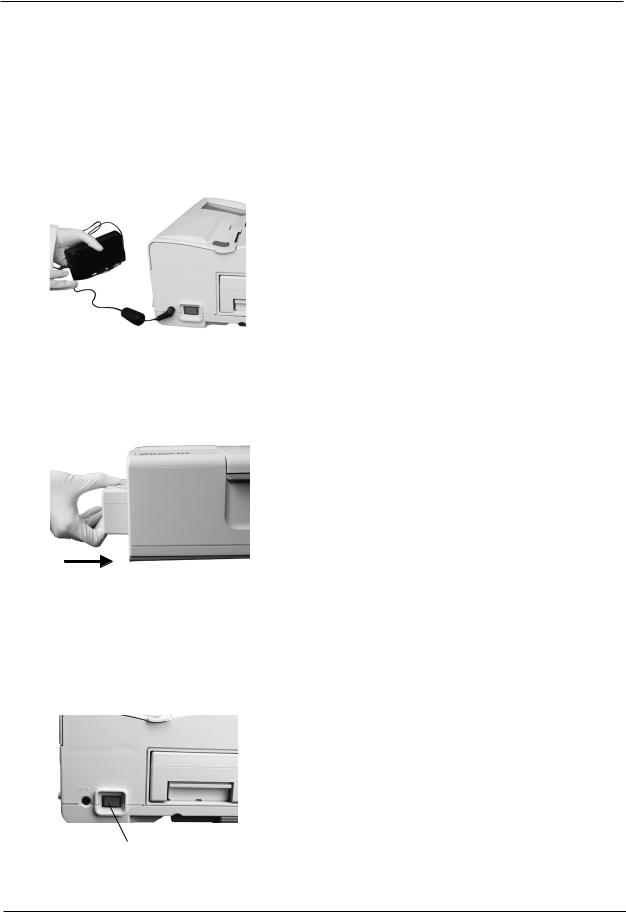
Fig. 2-1 Power Cord Connection
Fig. 2-2 Insert Battery Pack
1.Plug in the Power Supply
•Plug the power supply into the receptacle on the left side of the unit (Fig. 2-1).
•Plug the power cord into the power supply.
•Plug the cord into a grounded electrical outlet.
NOTE:To protect your OPTI CCA-TS2 and other electronic devices from damage caused by electrical power spikes, OPTI Medical recommends the use of a surge protector.
2. Install the Battery Pack in its Housing
•Push the battery pack into the opening on the left hand side of the OPTI CCA-TS2 (Fig. 2-2).
NOTE: The battery will need to be charged for at least 2.5 hours prior to using the OPTI CCA-TS2 on battery power.
It will be charged automatically whenever the analyzer’s external power supply is plugged into an electrical outlet.
The lower LED on the back of the analyzer turns green while the battery is being charged.
The top LED turns green when charging is complete.
3.Turn on the Power
•Locate the power button on the left side of the unit and push down to turn the power on (Fig. 2-3).
Fig. 2-3 Power Button
2-2 |
Operator’s Manual – OPTI CCA-TS2 |
2 SETUP
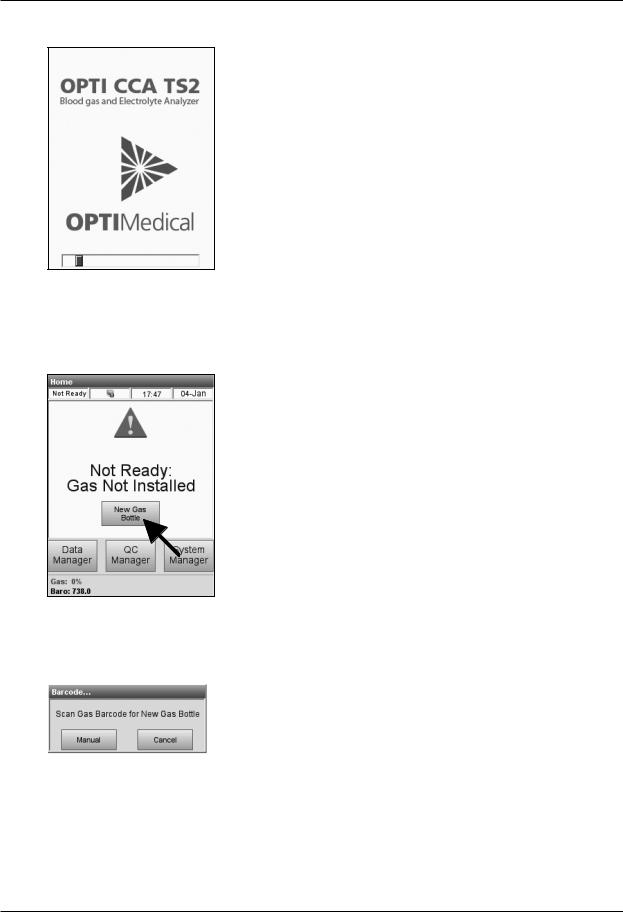
Fig. 2-4 Startup screen
Fig. 2-5 Select New Gas Bottle
Fig. 2-6 Scan Barcode
•This is the first screen that will appear after the power is turned on (Fig. 2-4).
4.Installing a New Gas Bottle
This screen will appear after initial power-up sequence, when no gas bottle is present (Fig. 2-5).
•Press <New Gas Bottle>.
•Open the gas bottle by unscrewing the cap.
•When prompted (Fig. 2-6), scan the new gas bottle bar code on the insert sheet by holding it 2-3 inches (5-8 cm) from the bar code scanner located on the bottom right-hand corner of the analyzer.
•The red line from the bar code scanner should cover the entire bar code.
•The analyzer will beep when the bar code is accepted.
•If the bar code is not recognized by the scanner the first time, try scanning the barcode again.
•Record the date of installation on the gas bottle for later reference.
NOTE: If the insert sheet is misplaced, you can enter the lot number on the gas bottle label manually. Press <Manual> in the Scan Bar Code Screen and enter the number using the numeric keypad.
Operator’s Manual – OPTI CCA-TS2 |
2-3 |

2 SETUP
Fig. 2-7 Insert Gas Bottle
Fig. 2-8 Insert Gas Bottle
Fig. 2-9 New Gas Bottle
Fig. 2-10 Ready screen
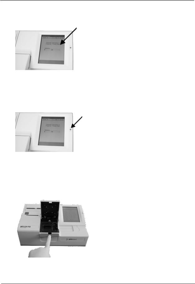
•When prompted (Fig. 2-7), insert the gas bottle in its housing and turn clockwise until fingertight (Fig. 2-8). Press  .
.
NOTE: The gas bottle expires 6 months after installation or after exceeding the labeled expiration date, whichever comes first.
NOTE: The bar code contains expiration information. Four weeks prior to expiration of the gas bottle, the OPTI CCA-TS2 will alert the operator once, as a reminder to order a replacement gas bottle.
•When this display appears (Fig. 2-9), press  to install a new gas bottle.
NOTE: If after the initial installation you need to remove a gas bottle and reinstall
the same bottle, respond
to the <New Gas Bottle?> prompt. The next screen will prompt you to enter the number of weeks in service using the numeric keypad (See section 7.5.3). Here you may refer back to the installation date, which was recorded on the gas bottle.
The OPTI CCA-TS2 will now begin to warm up and perform a gas purge, which will be indicated by a progress bar displayed on the screen.
Once the warm-up is complete, the <Ready> display appears (Fig. 2-10).
2-4 |
Operator’s Manual – OPTI CCA-TS2 |
2 SETUP
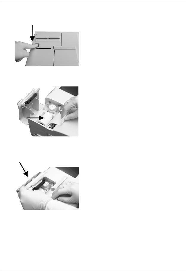
5.Installing the Printer Paper
•Press the red printer release button on the printer cover to access the printer (Fig. 2-11).
Fig. 2-11 Open Printer Cover
•Place the roll of printer paper into the paper tray.
•Pull the end of the paper upward and slightly
out of the paper tray (Fig. 2-12).
Fig. 2-12 Install Printer Paper
•Hold the paper and close the printer cover (Fig. 2-13).
•The paper will automatically feed through as the printer starts printing.
Fig. 2-13 Close Printer Cover
Operator’s Manual – OPTI CCA-TS2 |
2-5 |
 Loading...