


AUTOMATIC
SPRINKLER TIMER
Owner’s Manual PC-306/PC-406PS
For use with standard 24 VAC automatic sprinkler valves. These timers are designed for use in any 110 VAC /60 Hz ±10% AC outlet (240 VAC, 50 HZ for international version). The PC Sprinkler Series Timers provide simple programming and flexible schedules to meet your landscape watering needs. We recommend you read this Owner's Manual completely before installing the timer to ensure proper operation and safety.
Thank you for choosing the OPTIMA PC-306, PC-406PS Timer. Several innovative features allow you the flexibility to tailor your program to fit a variety of watering requirements; and, best of all, it is easy to program!
•Simple to use dials and buttons.
•Three available start times for each program to give you maximum flexibility.
•Off feature allows you to keep all your program settings while turning off your system when you want!
Just in case, if you have questions, please call us toll free at 1-800-742-9922. (U.S.A., Canada & Mexico only).ABOUT YOUR LAWN
Optima's PC Series Sprinkler Timer is the central unit that controls watering times for your automatic sprinkler system. The following infromation provides an overview of how the timer works.
Stations
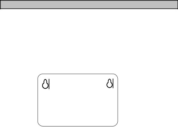
To meet the different watering requirements of your lawn, trees, flowers, and other landscaping, you can divide your yard into separate areas called "stations" or "zones".* Each "station" has one valve that controls multiple spray heads or sprinklers. For example, if you have 4 valves, you can divide your lawn into 4 "stations". See the figure below. (You cannot link more than one valve to one "station.") You can however, select a different length of watering time for each "station".
* In the sprinkler industry, the terms "stations” and “zones” have the same meaning.
Station |
|
Station |
||
3 |
4 |
|
||
|
|
|
|
|
|
|
House |
|
|
Station |
|
|
|
Station |
|
|
|
||
1 |
|
|
|
2 |
|
|
|
|
|
"Legend" for this manual is located on the next page.
1

LEGEND:
Up Arrow
Days of the Week |
SKIP |
|
MO WE FR |
|
|
|
|
|
|
|
|
TU TH |
SA |
|
|||||
|
|
|
|
|
|
|
|
|
|
|
|
|
|
|
|
||||
|
|
SU |
MO TU WE TH |
FR SA |
|
|
|
|
|
|
|
|
|
|
|
|
Down Arrow |
|
|
|
|
|
|
|
|
|
|
|
|
|
|
|
|
|
|
||||
|
|
|
|
|
|
|
|
|
|
|
|
|
|
|
|
|
|
|
|
|
A |
|
AM |
|
|
|
|
|
|
|
|
|
|
|
|
|
Confirm Arrow |
|
|
|
|
|
|
|
|
|
|
|
|
|
|
|
|
|
|
|
|||
|
|
|
|
|
|
|
|
|
|
|
|
|
|
|
|
|
|
|
|
Starts |
B |
|
PM |
|
|
|
|
|
|
|
S |
|
|
|
Water Icon |
|
|||
|
|
|
|
|
|
|
|
|
|
|
|
||||||||
|
|
|
|
|
|
|
|
|
|
|
|
|
|||||||
C |
|
|
|
|
|
|
|
|
|
|
|
|
|
M/ |
|||||
|
|
|
|
|
|
|
|
|
|
|
|
|
|
|
|
|
Manual On/Advance |
||
|
|
|
|
|
|
|
|
|
|
|
|
|
|
|
|
|
|
|
A |
|
1 2 3 4 5 6 |
|
MANUAL |
|
|
|
DURATION |
|
Indicator Symbol |
|
|||||||||
|
|
|
|
|
|
|
|
|
|
|
|
|
|
|
|
|
|
|
|
|
|
Stations |
|
|
|
|
|
|
|
|
|
|
|
|
|
Dual Program Button |
A |
||
|
|
|
|
|
|
|
|
|
|
|
|
|
|
|
|
|
|
/B |
|
Watering Schedule (Days)
You can choose how often to water your lawn in one of three ways: 1) by Specific Days of the Week (MO, TU, WE, etc.), 2) by Day Intervals (Every day, Every 2 days or Every 3 days), or 3) by a choice of MO, WE and FR or TU, TH and SA. A schedule of Specific Days of the Week is especially useful if you live in an area with local water restrictions that limit you to water, for example, on Mondays and Fridays only.
Start Times
You can program your timer to start watering up to three times in one day. For example, you could set watering Start Times of 3 a.m.,6 a.m., and 6 p.m. The system would then turn on the lowest numbered station at 3 a.m., and would sequentially turn on the next station when that one has finished. Only one station is watered at a time. The same cycle would repeat, beginning at the next scheduled Start Time, in this example at 6 a.m.
Watering Duration
Each "station" can be scheduled to water for a different length of time, from 1 to 99 minutes. For example, you might program Station 1 (your front lawn) to water for 5 minutes and program Station 2 (your flower bed) to water for 10 minutes at each Start Time.
TOOLS YOU NEED
•Phillips head screwdriver
•Four #10 screws 11/4")
•9 volt alkaline battery
•18 gauge color-coded, multi-strand direct burial wire for runs of less than 800 feet
(For longer than 800 feet runs, use 14 gauge color-coded, multi-strand direct burial wire)
•Watertight splice connectors
•Plastic mounting anchors - optional
2
HOW TO INSTALL
STEP 1: CHOOSE TIMER LOCATION
Select an INDOOR location near a standard 120 volt AC electrical outlet (240 Volt outlet for 50 HZ units). The location should be completely protected from moisture, direct sunlight and below freezing temperatures. (Important: DO NOT plug in the transformer until you hove made all wiring connections.)
WARNING: When choosing a location, to avoid possible damage to the timer:
•DO NOT install in area where temperatures are less than 32° F or higher than 120° F.
•DO NOT install on same wall socket as other high current draw products such as garage door opener, washer/dryer, air conditioner, etc.
•DO NOT install on outlet controlled by on/off switch.
 A
A 

 B
B 

NOTE: You may install the timer using two screws aligned horizontally.
1. Screw two #10 screws into the wall 3 1/2" (88 mm) apart leaving 1/8" to
1/4" (3.2-6.4 mm) of the head extended from the wall. If mounting on plaster or masonry walls, plastic anchors may be required.
2.Place the two keyholes "A" on the back of the timer over the screws.
3.To further secure the unit, open compartment cover and place screws (1 1/4" minimum length) through the lower two "B" holes.
STEP 3: WIRE VALVES
1. Choose Wire (wire not included)
For runs of less than 800 feet, use 18 gauge color-coded, multi-strand direct burial wire. For runs of longer than 800 feet, use 14 gauge color-coded, multi strand direct burial wire. Be sure the wire has the number of strands equal to the number of valves used PLUS ONE for the Common Wire (e.g. use 5 strand wire if there are 4 valves).
TIP: Spare wire strands maybe taped off for possible future expansion or trouble shooting use. Wire that will be buried underground should have watertight connections and be approved for underground use. Avoid placing underground wire in locations where it may be disturbed by digging or other movement.
2. Connect Valve Wiring to Timer
To open wiring area on timer, push the cover down over bottom panel. To lift panel, push in on panel and push bottom down. Each valve connects to the timer through two wires. One wire (usually the white strand) is connected as the "common" wire. All common wires should be spliced together at the valves to become a single wire that will connect to the terminal marked "COM". The second or "hot" wire (usually the color-coded strand) from each valve connects to one of the terminals numbered 1- 6. See figure on next page.
3

Connect the one common wire (usually the white strand) to the terminal labeled "COM". Connect the second "hot" wire (usually the color-coded strand) from each valve to one of the terminals numbered 1 -6 on the number of stations on your timer model. Connect wire from valve 1 to terminal 1, valve 2 to terminal 2, etc.
NOTE: Be sure the wire connections are tight and make good contact. Also, it is recommended that you join all splices with watertight splice connectors to prevent corrosion.
CAUTION: Wire only one valve to each terminal. Wiring more than one could result in damage to the timer. Also, if using more than one timer, do not share "common" wires between the multiple timers.
TIP: To avoid possible pump damage, "jumper" wire each unused terminal screw to a terminal screw in use,(if you are using a pump start relay). See figure below.
NOTE: Check local regulations to ensure compliance with any wiring, electrical or installation codes.
4
STEP 4: CONNECT TRANSFORMER
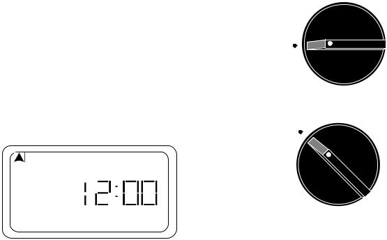
1. Turn dial to Off.
NOTE: In Off position display will be blank.
2.Plug pigtail connector (located at the end of transformer wire) into the two prongs to the left of the battery holder located under the cover of the timer.
3.Plug transformer into electrical socket.
4.Turn dial to Auto. The following display should appear:
SU MO TU WE TH FR SA
AM
TIP: If display does not come on, check the electrical outlet.
CAUTION: DO NOT plug in the transformer until you have completed and checked all wiring connections. DO NOT link two or more timers together
STEP 5: CONNECT BATTERY
Off
Auto
Connect a 9 volt alkaline battery (not included) to the battery terminal and place it in the designated position. DO NOT USE A RECHARGEABLE BATTERY. In the event of a power outage, the battery will temporarily preserve your Schedule (newly installed batteries can preserve programs for up to 1 month, see note*). Watering will not occur until electrical power resumes.
(*NOTE: Battery operates memory back-up only. You can program your timer with battery power only; however, the system will not operate the valves while on battery power.)
DEFAULT MODE: Should the battery fail during a power outage, the timer will default to watering every day for 10 minutes per station, starting 8 hours after the power resumes, until reprogrammed.
TIP: Replace the battery once a year at the same time you would replace household smoke detector batteries. When replacing, do not unplug the transformer, or you will lose all programmed settings.
CAUTION: Do not allow the battery to come in contact with the wire terminal strip.
You may now begin to program your new PC-306 timer.
Please turn to page 9 to program your PC-406PS timer.
5
 Loading...