

Page 1
Recumbent Bicycle
User’s Manual
Page 2

‘Zen and the art of Recumbent Maintenance’
First published 2002
All Rights reserved, 2002
All images and text
Optima V.O.F.
We would like to extend special thanks to
Tim Biesemans, Mark Scherpenzeel and countless
other Optima customers whose many photos helped to
decorate the pages of this manual.
Page 3
Congratulations and thank you, for buying an Optima!
About this manual
Why You Should Read This Manual
This manual was written to help you get the best of performance, comfort, enjoyment and
safety from your new Optima.
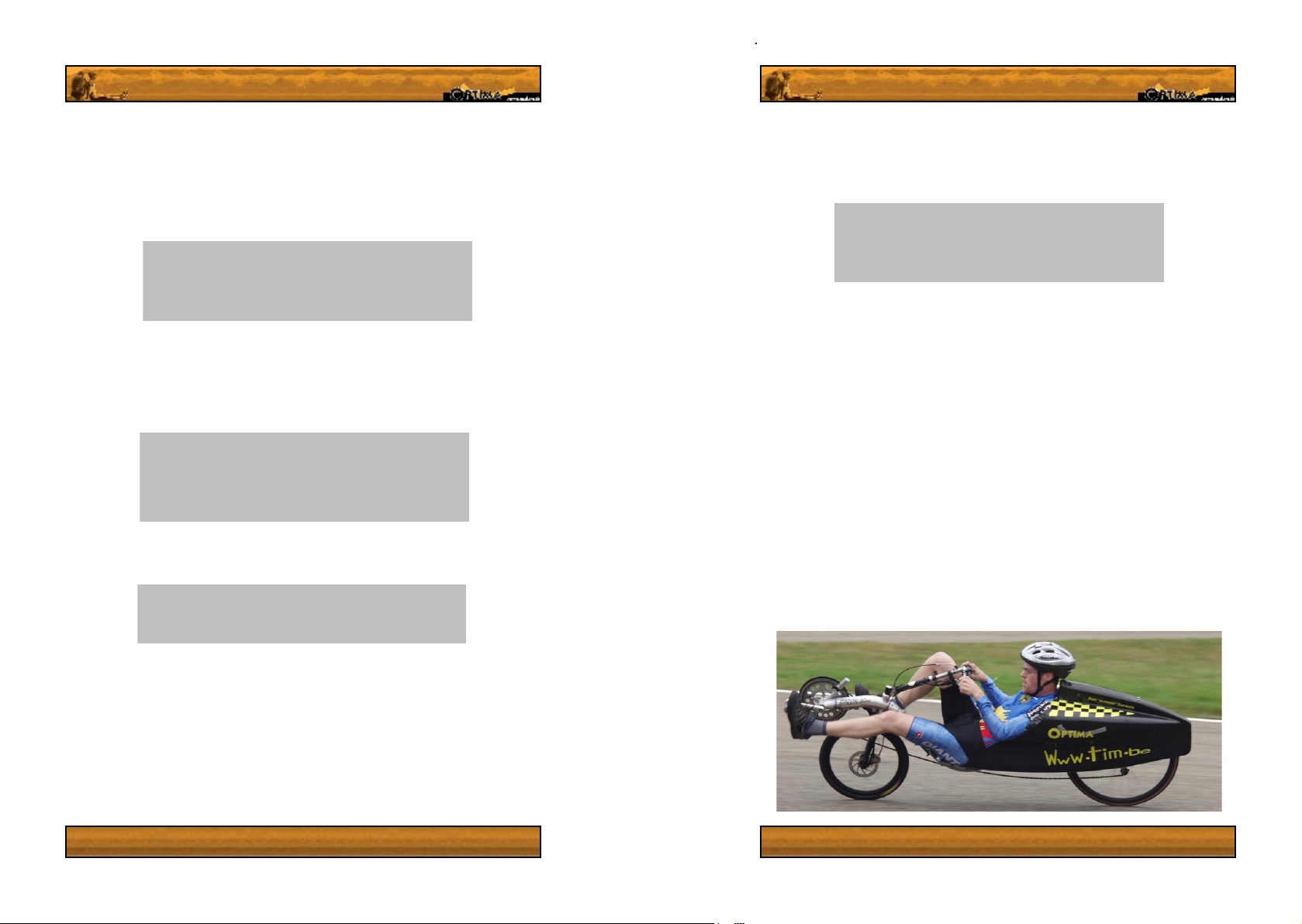
Whether you bought your Optima for running errands, commuting to work
or recreation and exercise, we welcome you to the effortless, comfortable
and fast world of
recumbent bicycling!
Before taking your bike out for a ride, we ask that you read this brochure
fully – we know you’re itching to go!
We would like to express many thanks to our customers who supplied
many of the photos included in this manual.
We hope that this manual will help you to enjoy your bicycle for many
years to come.
Caution! Whenever you see a grey box, be sure to read
it carefully. These boxes hold warnings and tips, some
crucial to the function or safety of your bicycle.
It is crucial that you fully understand your new recumbent bike; its features, characteristics
and operation, so that you get maximum enjoyment combined with maximum safety starting
with the rst ride. By reading this manual before you go out on your rst ride, you’ll know
how to get the most from your new Optima.
It is also important that your rst ride on a new bicycle is taken in a controlled environment,
away from cars, obstacles and other cyclists. This is especially important for individuals
who are not yet experienced in recumbent cycling, or for individuals riding a low slung
recumbent bicycle for the rst time. Do not overestimate your skills and potential. Riding
an unknown bike can lead to dangerous situations.
Optima strongly discourages riding your bicycle before reading the entire manual.
Warning! Bicycling can be a dangerous activity even in
‘optimal’ conditions. Proper maintenance of your recumbent
is your responsibility and it helps reduce the risk of injury
to yourself and others. This manual contains many Tips,
Warnings and Cautions which focus on important aspects
of your bicycle, its components and safe cycling. Many of
the Warnings and Cautions include text advising you of the
dangers which could “Lead to serious injury and damage to
your bicycle”.
Whenever any Warning! Or Caution! Boxes appear, keep
in mind that the following text is absent but applicable in all
cases:
Failure to follow this guideline could lead to a fall, damage to
your bicycle , serious injury and even to death.
We do not repeat this phrase everywhere because it would
give our manual a negative overtone. We all know how
much standard bicycle manufacturers warn you of the
dangers of cycling right? Keep in mind that this is true for a
recumbent, and that you have a reduced prole compared to
normal cyclists. Basically, be careful to ride with your head,
as well as your helmet, securely ON!
Page 4
To the experienced Cyclist.
So you’ve been riding a bike all your life, know all the tips and tricks… you really don’t
need to read this manual, right?
WRONG.
Even if you’ve been riding a bike all your life, buying and riding a recumbent for the rst time
should be accompanied by an renewal of your cycling habits, knowledge and assumptions.
Why? Because bicycles are going through some pretty dramatic changes in the technology
which affects function, handing, comfort, performance and safety. A big example – the
difference between a standard upright bike and a recumbent! Please read this manual.
A point of attention for parents
It is a sobering fact that many cycling accidents involve children. Make sure that your
child always wears an approved bicycle helmet when riding. It is the responsibility
of a parent or guardian to ensure the safety of their child. This means that it is the parent
or guardian’s responsibility to ensure that their child can operate the bicycle, that it ts
the child properly and that it is well maintained. It is also your job to ensure your child
is educated in the laws of the road, common sense and trafc awareness, and wears
sufcient protective apparel. We strongly advise you read this manual if it is the manual
of your child’s bicycle.
GENERAL
SAFETY APPAREL 1
HELMETS 1
EYEWEAR 1
REFLECTORS 2
LIGHTS 2
MIRRORS 2
SUPPORT AND UPGRADING. 3
RESPONSIBLE CYCLING 4
GENERAL SAFETY MEASURES 4
WET WEATHER AND NIGHT TIME CYCLING 4
YOUR OPTIMA BICYCLE 5
SETTING UP YOUR BICYCLE 6
ASSEMBLING FROM THE BOX 6
1. INSTALLING THE WHEELS. 6
2. INSTALLING LINKAGE FRONT STEERING SYSTEMS 8
3. RIDER FRONT WHEEL ALIGNMENT 9
4. BRAKE ADJUSTMENT & BLEEDING 12
5. MOUNTING MUDGUARDS 13
6. FITTING THE SEAT AND RACK. 14
7. INSTALLING THE PEDALS 15
8. INSTALLING THE PEDAL BOOM 15
9. INSTALLING THE FRONT DERAILLEUR AND CABLES 16
10. TIRES AND CORRECT TIRE PRESSURE. 16
11. HANDLEBARS 16
12. SUSPENSION 17
13. CHAIN LINE AND PULLEYS 18
14. BRAKES. 19
15. MOUNTING THE AERODYNAMIC COWLING (BARON OPTION ONLY) 19
RIDING A RECUMBENT BICYCLE 22
BEFORE YOU RIDE 22
SHORT PRE-RIDE CHECKLIST. 22
THE FIRST RIDE 24
TRAVELLING ON YOUR RECUMBENT 25
COMFORT AND QUALITY ACCESSORIES FOR YOUR RECUMBENT 25
MAINTENANCE 27
RECOMMENDED PERIODIC MAINTENANCE 28
EACH TIME YOU RIDE 28
WEEKLY 28
QUARTERLY CHECKLIST. 28
TOOLS FOR MAINTENANCE 30
Page 5
SERVICE TIPS 31
ADJUSTMENT OF THE HUBS. 31
HEADSET AND FRONT FORKS. 31
SPOKE TENSION 31
BOTTOM BRACKET AND CRANK 31
GEARS 31
STORAGE TIPS 32
TROUBLESHOOTING. 32
SUSPENSION
WHEELS AND TIRES
HUBS
CRANKS AND BOTTOM BRACKET
BRAKING
DERAILLEURS, CHAIN ROLLERS AND REAR CASSETTE
MISCELLANEOUS
FORKS AND HEADSET
PEDALS
OPTIMA BICYCLE MODELS 39
PERMITTED BICYCLE USAGE 40
RESOURCES 41
OPTIMA FACTORY 41
ACCESSORY LIST 41
WARRANTY 42
TERMS AND CONDITIONS OF GUARANTEE. 43
SERVICE RECORDS 45
WARRANTY FORM 51
General
Safety apparel
Many nations around the world, and their internal states, have strict requirements regarding
safety devices and their use in cycling. It is your soul responsibility to nd out what these
requirements are, in each and every state or nation you cycle and then follow them.
Helmets
‘If you don’t need a head, you don’t need a helmet’.
While not all nations and states require cyclists to wear approved protective headgear, we at
Optima strongly advise you to do so. Try to nd a helmet which complies to Snell, ANSI and
government safety requirements. Simple amoebic intelligence states that it is best to wear a
helmet (passed by these authorities) whilst cycling, whether the law requires it or not.
Many serious and fatal bicycle injuries could have been either reduced or avoided had the
cyclist been wearing a properly certied helmet. Your local bike store should have a range of,
or at least be able to order, helmets which suit your needs.
Caution! A correct helmet should t properly, and be fastened
securely according to the instructions of its manufacturer. A
good helmet will protect according to Snell, AISI or stringent
government regulations. Failure to wear a good helmet correctly
could lead to serious injuries or even death, which may have
otherwise been avoided.
For more information on helmets, please contact your dealer or a local bike store, they will
be happy to supply you with a helmet.
Eyewear
Any cycling involves airborne bugs, dirt and other objects that are just waiting to get at your
eyes. Higher speeds can also make ones’ eyes water and impair your vision. For this reason
we advise you wear sufcient eye protection, in the form of a quality set of glasses in all
conditions. Most sports and bicycle stores sell protective and fashionable eyewear.
Tip! To increase your vision in all weather conditions,
we suggest you buy a good pair of sports glasses, with
interchangeable lenses in at least one dark colored lens and at
1
least one amber, clear or yellow lens.
Page 6
Reectors
Reectors are important safety features, which are an integral part of your bicycle.
Most authorities worldwide require bicycles to be tted with front, rear, wheel and pedal
reectors. The requirements of these reectors should be able to be found through your
local government. Reectors are designed to use other light sources – car headlights,
street lights and the such to increase your visibility to other road users.
Caution! Check your reectors are securely fastened to your bike
regularly. Clean your reectors often, as mud and grime picked up
will limit the amount of light that can enter and exit the reector,
reducing its effectiveness. Do not allow baggage or yourself to
conceal or cover a reector.
Do not remove any reector from your bicycle
Lights
If you ride your recumbent during or before dawn and dusk it must be equipped with a
lighting system approved by the local government. It is also prudent and advised to install
a lighting system if you ride during bad weather conditions as well. Your local bike store
or Optima dealer should be able to supply you with a good lighting set and advise you as
to the best choices.
Warning! A good lighting system can never be substituted
for by reectors. It is your own responsibility to ensure your
bicycle is equipped with an acceptable lighting system, which
complies to the guidelines set up by your local authority. Failure
to follow this guideline may result in dangerous and fatal trafc
Battery lighting systems have the potential to be much more powerful than generator
systems, but they weigh more and have a limited battery life. Their constant illumination
is an advantage for the urban evening commuter, who remains visible all the time.
Caution! Be sure to install a WHITE front light and a RED rear
light on your bicycle. Failure to do so may violate local trafc
laws and will denitely compromise your safety.
situations.
Support and upgrading.
Although we strive to build ever higher quality products, your recumbent is not indestructible
and at some point something is bound to fail. With the constantly change and development of
the array of components available for bicycles, it is inevitable that at some point you will want
or have to replace a part or install a new one.
Caution! Replacing, changing and upgrading the componentry
on your recumbent may have an effect on the bicycles warranty.
To avoid any unpleasant surprises, consult your Optima dealer
before making any changes to the original equipment of the
manufacturer. (OEM)
If you do not have your new component installed by a professional and approved Optima
mechanic, then make sure to fully read the instructions of the new component and carefully
follow the manufacturer’s installation procedure. Also make sure to conrm that the new part is
completely compatible with your bicycle and its current (OEM) setup. Just because you have
the ‘mechanical touch’ does not mean that you will know everything about a new component,
especially if it is a new type of an existing product, or a completely new idea.
A popular upgrade nowadays is the installation of suspended forks. Finding a suitable
suspended fork for a 20 inch front wheel can be a tricky process, and we advise you contact
your dealer or Optima before making any decisions for their advice. Keep in mind that installing
suspension forks will change the geometry of your bicycle and in turn, your recumbent’s riding
characteristics.
Another popular upgrade is to install disk brakes. Realize that in installing a disk brake, you
are loading the bicycle’s forks differently and you may be reducing their service life. The extra
braking power provided by disk brakes also increases the loading on the frame.
If at any point you are worried about compatability and specic components or have any other
questions, contact your dealer and they will be able to help you. Your dealer is there to help
you in making decisions and provide you with the help of somebody whose profession it is to
know everything there is to know about these bikes and parts. Asking his opinion will allow you
to get the best out of your bike, and avoid unpleasant surprises after buying a component.
Generator lighting systems will never run out of power, but require the cyclist to be moving
for the lights to function. These systems are generally lighter than battery powered lights,
but the more powerful you want them to be, the more rolling resistance the system will
produce. Generators can be housed in the standard tire rollers, or in the front hub.
Mirrors
Looking behind you on a recumbent bicycle is trickier than doing so on a standard bike.
For this reason Optima strongly recommends that you install at least one rear view
mirror, preferably on the left hand side of your bicycle for countries where trafc drives
on the right, and the right for countries where you drive on the left.
2
3
Page 7
Responsible cycling
Recumbent cycling, like all other sports has its thrills and exhilarations, but also its dangers.
A cyclist is in control of his or her own vehicle, and his safety is primarily in his or her
own hands. Dangerous or unusual situations should be met with cautious behavior and
preventative measures from the cyclist him or herself - the rst of which is to slow down.
Both Optima and the local government cannot therefore be held accountable for your
mistakes or misjudgements.
General safety Measures
Caution! Be sure to follow these guidelines to ensure your own safety.
· Always perform the pre ride checklist on page 18 before every ride
· Wear your helmet whenever you are on your bicycle
· Take care not to let the wheels, chainrings, chain, cables and other bicycle parts injure
you
· Recumbent pedals are higher than those of a normal bike, and are in a position that
your feet do not fall naturally, as they are on a standard bicycle. For this reason always
wear appropriate, fully closed shoes and buy a pair of ‘clipless’ pedals, to keep your
feet on the pedals. Do not use pedal straps.
· Know your bike and its controls.
· Control your speed. Speed is dangerous to you and strenuous to your bike.
· Stay rmly on the ground. Jumping a normal bicycle can be dangerous, but at least on
a normal bike you can move about to facilitate a safe landing. On recumbent bicycles
this is not the case. Do not jump whilst riding your bicycle.
· Wear highly visible clothing. Low swung recumbents, above all, should be ridden wearing
bright and visible colors to increase your chances of other road users seeing you.
· Ride as if you were invisible. Keep an eye on what is going on in the trafc around you.
The best way to avoid a collision is obviously to see it coming beforehand.
· Never overtake in a corner. Never. Because you are so low, its likley that Vehicle drivers
will not to see you and will drive you off the road or into the gutter. (this hurts!)
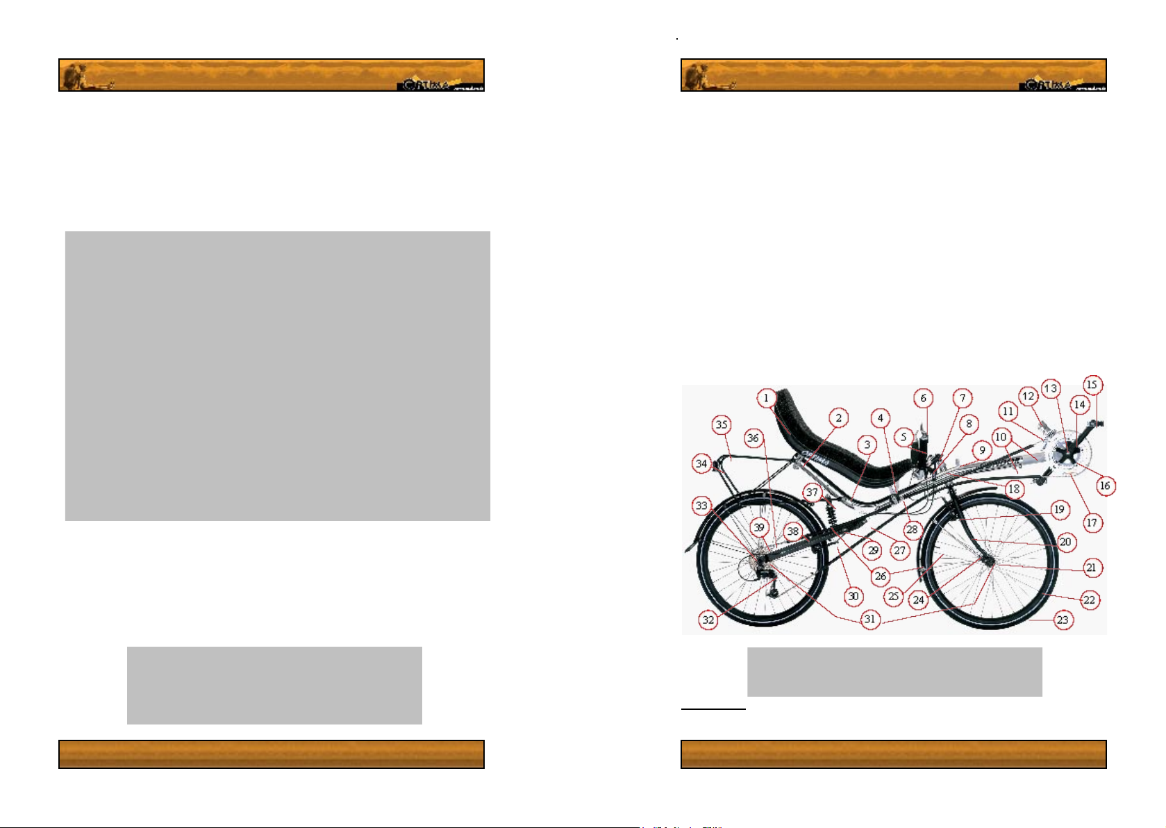
Your Optima Bicycle
1. Seat
2. Upper adjustable seat
xture and upper rack
xture
3. Lower rack xture
4. Lower seat xture
5. Handlebars
6. Gear shifting levers (can
vary in position)
7. Stem
8. Brake levers
9. Bike computer mount
10. Pedal extension tube &
fastening bolts
11.
Front derailleur post
12. Front derailleur mounting
sheath
13. Bottom bracket
14. Crankset
1
15. Light xture (obscured by
chainwheels in photo)
16. Front chainwheels
17. Headset and Headtube
18. Front brake (rim brake)
19. Front (suspension) Forks
20. Hub
21. Wheel rim
22. Tire
24. Location of front disk brake
xture on the left side of bike
(not on all forks)
25. Valve stem
26. Mudguards
27. Rear suspension pivot point
28. Chain roller
29. Lower adjustable rear shock
mount
30. Rear brake (rim brake)
31. Wheel dropouts
32. Rear derailleur
33. Rear cog cassette /
Freewheel
34. Reector
35 Optima baggage rack
36. Chain
37. Rear shock absorber
38. Location of light generator
xture, left side. ( Not
on ‘Baron’, ‘Stinger’ or
‘Cobra’ )
39. Location of rear disk
brake xture, on left side
of bicycle.
Wet weather and night time cycling
Slow down in the rain and increase the distance between you and your fellow road users.
Avoid busy or dangerous roads. Realize you can be partially hidden in the spray following
vehicles. If you have lights, we suggest you turn them on in the rain. Ride in a restrained
fashion. Brake earlier, and more gently than when it is dry.
We strongly suggest you buy bright, reective cycling clothes for bad weather or night riding.
We also suggest you stick to routes you already know when conditions are bad, this way
you will have a better idea of what to expect. Keep this in mind when riding in the rain.
Caution! Precipitation signicantly increases your chances
of being involved in an accident. Wet weather reduces the
traction your bicycle has to the ground, it negatively effects
braking performance and it reduces visibility. These things
happen to you on your bicycle, and to all other road users.
4
Warning! Do not ride a bicycle that shows any sign of
malfunction or damage. Take your recumbent to a bicycle store
and do not ride the bike until the problem is xed.
1
For parts found only on linkage steering models, please see gure 9.1. For parts found only on
the ‘Rider’ please see gures 10.1 and 12.1
5
Page 8
Setting up your Bicycle
Now that you have opened the box and unpacked your new bike – How do you get this thing
working?! Please follow the instructions and suggestions given in this chapter carefully, to
ensure you can start off your recumbent cycling addiction safely and securely.
Assembling from the Box
Your bike will arrive partially or fully assembled, depending on where you live. Now all you need
to do is follow the following steps in the order written, and you’ll be riding your recumbent in no
time! Some steps will only apply to certain models, in which case this will be clearly stated.
1. Installing the wheels.
For ease in construction and accessibility it is best to start by mounting the wheels. Optima
bikes come with either bolt on or quick release wheel fastenings, depending on the model
and specications.
The rear wheel is fastened using a quick release lever for standard
hubs and bolts for SRAM’s dual drive or 3x7 derailleur/hub gear
systems.
When removing or replacing any rear wheel, make sure the chain is
fed properly around the cogs on the wheel, as seen in gure 6.1.
Quick release fastening allow for fast installation and
removal of the wheels. Properly fastened quick release
wheels are in no way less safe than bolted wheels.
To install the wheel, simply pull the lever on the wheel
outward to the unlocked position (g 6.3). After unlocking
the mechanism, feed the wheel into the forks or the frame.
Ensure that the wheel is fully inserted in the frame, to prevent
the brakes dragging on the rim or disk. If the brakes drag
when the wheel is properly inserted, readjust the brakes.
Now press the lever to the closed position, as seen in gure
6.2. (The nut on the opposite side to the lever may need to
be tightened or loosened to allow for the closure of the lever
to clamp the forks properly). To remove the wheel, unlock the wheel by pulling the lever. You
may need to unscrew the bolt on the opposite side slightly to get the quick release skewer past
safety knobs on the dropouts. If you are not already experienced in the use of quick release
skewers, see the manufacturer’s procedures in the enclosed information package for proper
use. Otherwise ask the sales representative or a local bicycle store for assistance.
Warning! An improperly fastened quick release lever could lead
to the dislodging of the wheel during braking, leading to serious
injury and damage to your bicycle.
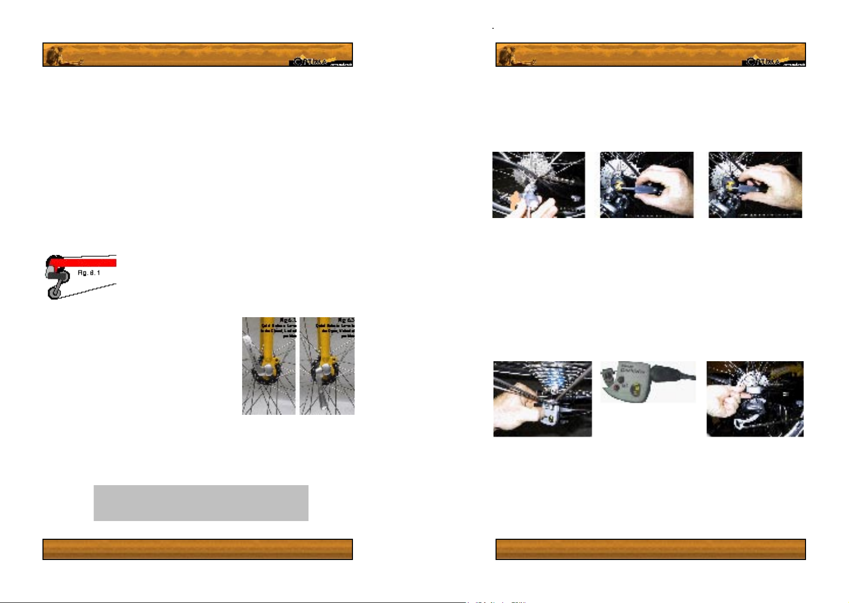
3x7 derailleur and hub gear system Installation and removal.
To install (or remove) the rear 3x7 wheel, rst put the left handlebar shifter to the lowest gear
(position on the grip 1). Feed the wheel into the frame ensuring that the cog cassette is on the
right hand side of the wheel, the same side as the rear derailleur. Now bolt the wheel to the
frame, using a 15 mm metric spanner. Once the wheel has been fastened, feed the shifting
linkage chain into the gear shifting roller and slide the shifting roller onto the hub axle stub
(g 7.1). You will hear and feel a positive click when it is properly engaged. Now track the link
chain around the roller.
The next step is to connect the shifting chains threaded stub with the shifting cable connection
unit. This is done easily, by simply feeding the stub into the unit, as seen in images 7.2 and 7.3.
Feed the connector unit onto the stub to the point at which most of the slack is gone from the
shifting cable and release the block. Now check that the handlebar shifter units can engage
all three gears. If the top gear cannot be engaged, you will need to loosen the connector unit
and allow a little more slack in the cable.
To move or remove the connection unit from the shifting chain stub you will need to pinch
the unit at it’s end, pressing the small square plate of brass in to release the ratchets which
prevent the unit from slipping (see g 7.2) To clamp the unit to the stub again, simply release
the button
Dual Drive derailleur and hub shifting system wheel installation and removal.
The hub will need to be bolted onto the frame using a 15mm spanner. Once bolted on you can
install the gear shifting linkage unit.
Start by putting the thumb lever on the handlebar shifting unit to the leftmost setting, with one
dot. When you look at the hub connection unit, the yellow indicator in the small window should
be as close to the axle hole as possible, (g.7.5). Next, you will need to press the black shaft
sticking out of the top of the connection unit in fully so that it sticks out of the bottom of the
unit. This will not be possible if the thumb shifter is not in position 1.
6
7
Page 9
Once you have done this, feed the unit onto the protruding hub axle stub
on the right, derailleur hand side of the bike. Once you cannot push the
unit any further, reach your nger underneath the unit and push the shaft
back up as seen in gure 7.6. If the shaft will not move, remove and ip
over the unit and push the black lever inside the unit down towards the
unit’s base (as seen in g 8.1) and try again. It should now work.
Warning! Make sure that the gears work properly before
riding your bicycle. Badly adjusted gears could lead to the chain
skipping or jumping off the cogs resulting in frame and spoke
damage, and potentially dangerous trafc situations.
2. Installing linkage front steering systems 10.4
Setting up the steering linkage (All 2 and 3 wheel linkage steering models)
You will now need to connect the master to slave steering linkage. This may have already been
done, depending on where you live. You may however need to disconnect and connect the
linkage at some time anyway. To disconnect the linkage, pull the safety pin off the shaft (gs 8.2
and 8.3) and pull it out of the hole at the foot of the socket and shaft (g 10.4). To (re)connect
the linkage, make sure the safety pin is removed. Then push the linkage’s socket onto the
slave joint ball (seen bare in g 10.5) Once the socket is correctly around the ball joint, you will
be able to slide the safety pin back into the socket’s ange (g 10.7). If the pin will not go in,
the socket is not properly on the ball joint. This may require some force. If you cannot do it by
hand, give the socket moderated a tap with a rubber mallet to connect the joint properly. Once
properly on the ball joint, (Fig 8.7) replace the safety pin and clip it fully over the linkage shaft,
and it will snap itself closed. For instructions on aligning the steering system, please go to the
next page, and read the section entitled ‘Aligning linkage steering systems’.
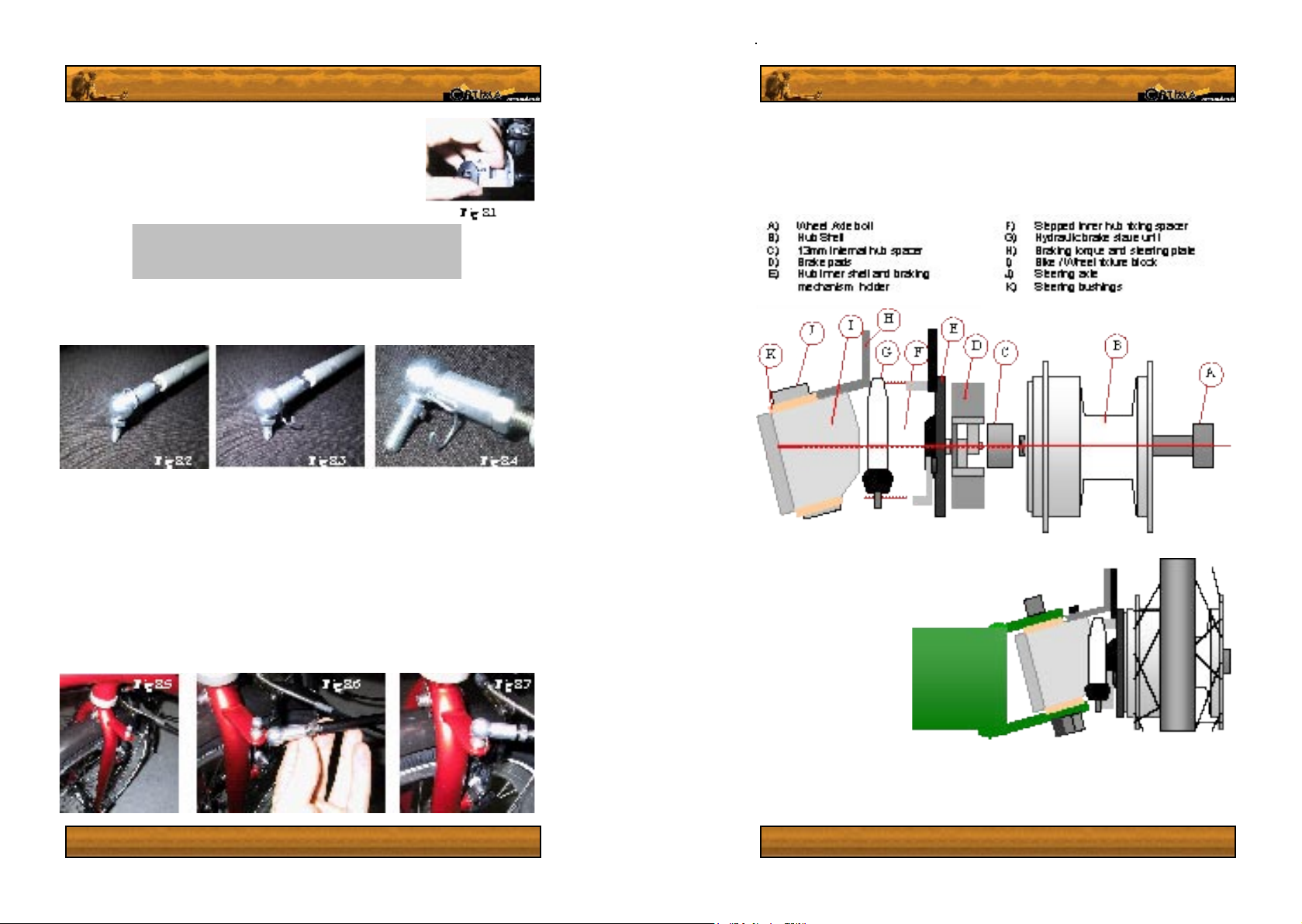
3. Rider Front wheel alignment and installation
All export models of the ‘Rider’ are delivered without the front wheels fully assembled. Please
follow these instructions carefully to ensure you install the wheels properly. Failure to do so
may result in hub damage, breaking malfunction and serious resultant injuries.
Assemble the wheel to the
frame, in the order depicted
in gure 9.1, with the braking
slave unit on the front side
of the hub as in g 9.2. The
brakes will have been aligned
befor e shi pp in g so all you
ne ed to do is mou n t th e
wheel as shown in g 9.2 and
fasten the axle bolt tightly. If
the wheel bolt is not sufciently
tightened, the brakes will drag
and the wheel may work itself
loose.
While screwing the hubs in,
gently squeeze the brake levers a few times, to ensure that the hub shells are well centred.
If one or both of the brakes drag, you will need to adjust them. This should not be necessary
for the rst assembly. To see how to adjust the brakes, see section 4 on page 12, brake
adjustment & bleeding.
Fig
9.2,
rider
8
9
Page 10

Measuring up front wheels (‘Rider’ only)
The front wheels should have been properly
aligned on the factory oor, but will need periodic
adjustment. To adjust the rider’s wheels, begin
by making sure that neither of the front wheels
has any buckling in it. Buckling will bring error
into the necessary measurements and will result
in a relatively large error in the setup. Also
ensure all steering plates are securely fastened.
Once the rims have been made true, point
them straight ahead and measure the distance
between the leading edge of the inner side of the
brake rim on both wheels (L.E., gure 10.1), and
the distance between the trailing edge (T.E.) of
each inner side of both rims across the bicycle.
Take the average of these measurements,
subtract 2 mm, and this will be your guideline2.
Once you have taken these measurements, cut
one length of wood or string (preferably wood)
to the length you have just dened. Once you
have cut it, nd the half way point on the beam
or string and mark this point clearly. Be sure to
do this accurately! Now that you have got all of
the necessary measurements, you can start the
alignment process.
Aligning linkage steering systems.
The rst step is to ensure that the steering master block (A, gure10.1 and 11.2
– present on all linkage steering models) is parallel to the central slave steering
block (C, or the front fork) . See gure 12.1 for an example. Do this by using a
50cm (20 inch) ruler, or any object you know to be perfectly straight of similar
length. Remove the integrated lower seat xture and chain guide3 to get an
unobstructed line between the two steering elements. Now get your ruler and
hold it along the side of the master and central slave steering blocks as seen
in gure 11.2. For forks, allign the wheel with the master block. If the slave
block or fork points to the right when the master block is straight (gure 10.2),
you will need to shorten the linkage bar. If the steering block points to the left
(gure 10.3, you will need to lengthen the linkage bar. Do this by loosening the
locknut (g 11.2, G), then loosening the head socket of the linkage (g 11.2,
F) from it’s plate and screwing it in or out to adjust the length of the linkage.
Retighten the locknut once you have the linkage at the correct length.
Once the two steering blocks are in
line, you will need to adjust the slave
to wheel linkage bars (E, g 10.1). This
process requires that the handlebar be
pointed straight ahead, and remain
that way until the process is nished.
Failure to do so will result in your
wheels not being properly in line.
You will now need to use the wooden
beam or string length you just cut and
prepared. Remove the pedal boom
from the frame, as you will need to
use the cut in the bottom of the frame
where the boom fastening bolts are
to align the wheels precisely, using
the half way mark you made on your
balancing beam or string. Hold the
alignment beam or string perfectly
hor izontal with i t’s center p oint a t
the groove (see g. 11.1) Using this
groove as a guide, align each wheel
individually by undoing one end of the
steering linkage bar, undoing the safety
locknut on the free end and moving the
end socket in or out by twisting it on
its thread. Align the wheel by replacing
the socket in the wheel’s steering plate
to check whether the center point lines
up with the frame when in contact with the inner surface of the rim. Once you have aligned
both wheels, check that the handlebar is still pointing straight ahead. The alignment beam or
string should now just touch both rims, when it’s center point is at the groove in the frame, as
seen in g. 11.1.
1
3
Part numbers 4 & 28, Figure 5.1 ‘Your optima Bicycle’
Fig 10.3
10
11
Page 11

4. Brake adjustment & bleeding
All brakes wear with time and temperature variations can sometimes lead to the necessity
to adjust the brakes. Most braking systems on Optima bicycles come with a separate
manufacturer’s information package containing a complete instruction manual. Please refer
to these manuals to set up and adjust your brakes.
‘Rider’ hub brakes
There are three main ways of adjusting the brakes: by the bolts holding the slave piston, by
the adjustment on the slave piston and via a small Allen key on the brake lever.
5. Mounting mudguards
A) Hub inner shell
B) Hub ange
C) Bike / Wheel xture block
D) Brake actuation lever
E) Hydraulic slave unit
F) Slave unit adjustment holes
To make any major adjustments to the brakes on the two front wheels, move the upper xing
bolt on the brake slave unit (E, g. 12.1) up or down on the adjustment holes on the braking
torque arm (F). If the brakes are only slightly out of adjustment, you can make small adjustments
by pulling the rubber boot on the under side of the slave cylinder down off the ridge on the
cylinder body. This will reveal a notched surface on the slave piston (K, g 12.1) which can be
adjusted with a 8mm spanner. Turn it clockwise whilst looking down the body of the cylinder
to the piston to tighten the brakes and counter clockwise to loosen them.
If at any point you remove the Braking torque and steering arm (I, g. 12.1) you will need to
replace it as follows. First, mount the hub on the bike/wheel xture block (I, g 9.1) making
sure that the inner hub spacer (F, 9.1) and the hub inner shell (E, 9.1 and A, 12.1) are well
centered on the bike/wheel xture block. Once you have screwed the hub in reasonably rmly,
Tighten the Steering arm base bolt (G, 12.1) slightly, followed by the braking torque bolts (H,
12.1). Once you have snugged both sets of bolts in, securely fasten the steering arm base
bolt before the braking torque bolts.
Another method of setting up the ‘Rider’ brake, is to adjust the reach of the brake lever. Please
refer to the enclosed Magura info package for information on how to do this.
G) Steering arm base bolt
H) Braking torque bolts
I) Braking torque and Steering arm.
J) Steering linkage fastening point
K) 8mm Brake adjustment socket on slave unit
L) Brake slave unit cylinder
Fig. 13.1 Fig. 13.2
If you ordered mudguards with your bicycle, they will be fast and
easy to install.
Remove the wheels from two wheeled bikes and the rear wheel
from the rider to install the mudguards. For the rear wheel, screw
the mudguard to the bicycles rear fork at its base, using the rubber
spacer and bolt provided. (Fig 13.3), placing the spacer between
the mudguard and the frame. Now attach the support rods to the
rear swingarm via bolt holes located at the top of the swingarm,
right above the wheel dropouts. (These are similar to normal bike
Once you have attached these support rods (13.3, b), you will need to attach them to the
Fig. 13.3
mudguard itself. This is done using the headless clamping bolts (a), nuts (d) and holders (c)
supplied. Feed the rod through the eye of the holder, insert the holder into the metal attachment
arm of the mudguard and screw the bolt onto it, clamping the rod in place (g 13.1).
Rider mudguards fasten to the braking
torque arm and steerin g plate, on the
front and rear bolt, as seen in gure 13.4.
The installation procedure is the similar
to two wheel ed bicycles, however you
do not attach the base of the mudguard
to the frame and only x it from one side.
This construction may look weaker than
the double side frame secured method
but the rods are strong enough to hold
the mudguard in place, as long as it is
installed properly.
rack mount points, but not to be used for racks.) See g 13.2.
Fig. 13.3
12
13
Page 12

Caution! Bleeding hydraulic brakes of air is a potentially
dangerous process if not done correctly. We strongly advise
that you get your brakes bled by an experienced bicycle
mechanic if you are not absolutely certain that you can do it.
Bleeding Hydraulic brakes
For those who can bleed their brakes properly, Optima offers standard and Rider bleeding kits
to its customers
a bleeding kit, using the address found on page 30, resources.
4
1
, which come with a complete instruction manual. Please contact optima for
6. Fitting the seat and rack.
Caution! Do tighten the bolts holding the seat onto the seat
frame over 6 NM-1. Failure to follow this guideline will either
immediately crack your seat, or reduce it’s service life. Let the
For low handlebar models, please go to step 10 on page 17 rst. The seat must be installed
using the rubber spacers, 3 & 6 mm Allen keys and the 10 mm bolts provided. The seat
mountings allow for adjustment of the angle of the seat, of approximately 5 degrees (g
14.2). The seat mounting frames are fastened using a 6mm allen key, and a 5mm allen key
on the bolt holding the seat frame and chain router on the lower right hand side. The rack
xes to the frame using the upper seat xtures and the bolts half way down the seat support
tube.
If you own a Orynx or Dolphin, your rack, if you ordered one, will be different from the rack
on the bicycle shown in gure 1.1. This rack fastens onto the same points as the standard
rack, but it integrates the upper seat frame. (g. 1.1, part numbers 2 and 35) The Stinger
rack fastens to the upper adjustable seat mounting, and is connected to the seat itself with 4
bolts instead of two.
7. Installing the Pedals
Now get the Pedals, and slightly grease the thread on
them. Feed the pedal thread into the cranks manually,
remembering that the left hand pedal has an inverted
thread (To tighten, turn counter-clockwise.) The right
hand side has a normal thread (turn clockwise to tighten).
8. Installing the pedal Boom
Loosen the screws on the bottom of the frame where the boom enters the frame feed the boom
into the frame, ensuring the derailleur post, if present, is on top and the chainwheels are on
the right hand side of the boom, in the direction the bike travels. If you own a condor or a rider,
keep in mind that for any extension or shortening of the pedal boom, you will need to undo
the derailleur cable rst. When you cut the cable to length, take note that doing so will limit the
extent to which you can extend the boom in future, without buying a new inner cable.
Start the setup process by setting your seat in the most upright position possible. Now adjust the
length of the pedal boom up so that your knee is slightly bent when your heel is on the pedal at
it’s full extension. Make sure that you feel comfortable with the setting – some people like their
pedals closer than others. If you did not tell us your leg length in the ordering procedure you
will now need to adjust the chain length5, as described on page (XX). If you have short legs,
you may even need to cut down the pedal boom to allow for the bike to be set up correctly. We
advise you do to a local bike store to have this done. If you cannot or wish to do it yourself,
use a good jig and a sharp metal saw to cut the pedal boom down.
To get the pedal boom aligned properly in rotation, line the boom up with the seat and handlebars.
Once you have the boom properly aligned, tighten the bolts rmly.
Tip: When adjusting the angle of your seat, you will need to
change the extension of the pedal boom slightly. If you lay the
seat back, reduce the extension of the boom. If you bring the
seat upright, lengthen the boom extension slightly.
4
Rider kit comes with an extra syringe and lead for the dual slave system. This special kit is
cheaper than buying two Magura service kits, which you would otherwise have to do.
14
Caution! The pedal boom MUST NOT be extended beyond
the poi nt at which the end of the boom is les s t han 10
mm inwards f rom the inner of boom clamping bolt (A, fig
16.2). Failure to follow this guideline will result in increased
fatigue and potential failu re o f the fram e of your bicycle.
5
This requires a special tool: a chain breaker or pin pusher. Go to your local bike store if you don’t
know how to use one or are not condent in adjusting your chain, as a badly connected chain will
break.
15
Page 13

9. Installing the Front Derailleur and cables
The cable will have been fed through the boom during the manufacturing process, and you will
see the end of the cable (B, Fig 15.2) sticking out of the boom just below the front derailleur post
(C). Bend the cable round and feed it into the cable stop (D), on the left hand side of the front
derailleur boss (again, in the direction the bike travels). For exact tuning of the front derailleur
please see the instruction manual of the manufacturer, included with your bicycle information
package. Align the derailleur so that the chain passes parallel to the front derailleur’s cage, by
loosening the clamp on the derailleur clamp sheath (E, g 15.2). This will avoid the necessity
to readjust the cable. Now that you have set up the extension and derailleur, you may want to
cut the front derailleur cable to length. Only do this if you are condent you can do it properly!
Tip: if two people will be using the bike, to install the front
derailleur (inner and outer) cable length according to the
settings of the tallest user!
10. Tires and correct tire pressure
To ensure proper traction and safety, tires must be inated to the correct pressure (60–100% of
max, unless otherwise stated). If the pressure is too low, the rolling resistance will be signicantly
higher than usual and the tires will wear at a faster rate. If it is too high, the tires will deform
and eventually fail. The max tire pressure and often the advised range can be found on the
sidewall of the tire, in both p.s.i. and bar. Some tires will also have an arrow indicating their
intended rotational direction.
Warning! Make sure your tires are properly infla te d as
described above before riding. A tire at low pressure will
cause more drag, wear faster, and may lead to handling
pro bl ems or even tire folding in emergency maneuvers.
11. Handlebars
If you bike is delivered in a box, some handlebars may not be mounted. For understeer models
mount the handlebar and stem before the seat, using a 6mm allen key. Adjust the angle of
the handlebar so that it falls into your hands comfortably whilst they are in a straight line with
regard to your wrist. Otherwise adjust it to an angle that feels natural to you. A properly adjusted
handlebar will reduce fatigue all the way up to your shoulders and neck. For above steering
models, you may need to install the stem. (turn page)
Installing a above steering tiller is a simple process. Start by
feeding the stems base onto the fork steerer tube, makins sure that
the clamp ring is abound the base of the stem (with exeption of the
baron stem, see the next paragraph for baron instructions). Once
the tiller is slid onto the steerer tube, lean it forwards and insert the
top clamping screw into the hole at the top of the stem. Tighten this
screw Untill all paly is gone from the bearing races. Then swing the
stem back and align it with the front wheel. Now tighten the collar
around the stems base to lock the stems angle. Both tillers can be
adjusted in angle by screwing the angle adjustment screw in or
out. The universal tiller can be adjusted in reach, by loosening the
screw in the collar clamp of the top seaction and sliding it in or out.
For the Baron, Slide the stem onto the forks steerer tube, then
place the headset cap on top of it. Insert the bearing pressure screw and tighten it untill all
play is gone from the bearings. Now allign the stem with the front wheel and tighten the bolt
found behind the steerer tube and under the stems arm.
12.Suspension
The suspension will have been fully prepared in the Optima factory.
No further work is necessary, however you may want to tune the
suspension preload6 to suit your weight and riding style. If you
have an air shock absorber, adjustment will require a special highpressure pump, available from better bicycle stores. If you have a
coil spring shock absorber, adjusting the preload is easy. Simply
twist the spring and bracket on the stationary body, clockwise to
increase the preload and counter clockwise to reduce it. This will
cause the bracket to move up or down on its thread, and cause the
pre compression factor to increase or decrease, resulting in a softer
or harder feel to the suspension (see g 19.1). Further adjustment
is possible by moving the lower xture to another of the three
anchoring holes on the rear wheel fork (see image to the right).
The further from the pivot point the lower xture is, the harder the
suspension will be. Correctly set up suspension will sag about 1/5
into its travel when the cyclist sits on the bike. This setting ensures
the suspension will function correctly and effectively.
Optima bicycles are equipped with a spring that is best suited to rider’s weights of 60–100kg
(130- 220lbs.). If you fall outside of these bounds, you may want to consider visiting a good
bicycle store, which should be able to help you nd a new spring that suits your weight.
Tip: If you are carrying lots of baggage (on the rack or frame)
you will need to tighten the spring preload, relocate the lower
xture and maybe even buy another spring to ensure proper
suspension function.
16
6
Preload is the precompression factor of the spring. This denes and how soft or hard the suspension
function will be. Increasing it will make for a rougher ride, decreasing it will result in a smoother ride.
Ask your dealer for tips on optimal setup for all conditions.
17
Page 14

13.Chain length and Pulleys.
Pulleys
Each Optima bicycle is equipped with at least one chain guiding pulley, which
will not need much maintenance. These pulleys both guide the chain and
prevent the bicycle’s rear suspension from being inuenced by pedalling
forces. The fastenings for the pulleys double as anchorage points for the
protective chain tubes, which reduce the amount of dust that gets to your
chain and protect your clothing.
14.Brakes.
The brakes may need slight adjustment out of the box bus should be working properly.
Optima sets up its bikes so that the right hand brake lever is for the rear brake, and the left
hand lever is for the front.
Be careful in learning to use the brakes on a recumbent – the rear wheel will break out easily
if you use them over zealously. On a recumbent you cannot move around like on a normal
bike, making a recovery more difcult.
It is crucial that the chain is guided over the pulleys correctly, as failure to do so could result
in damage to the bicycle frame and seat. Make sure that the larger diameter pulley (70mm /
3 in diameter) guides the chain as it goes from the top of the rear cog cassette, to the top of
the front chainwheels of the crank.
The three low swung Optima’s (Baron, Cobra and Stinger) have 1 or two return pulleys to
Fig 18.1 Baron, Cobra and Stinger chainline
Standard chainline
pulleys and through all tubes, put the chain into the smallest front chainwheel and smallest
rear cog. The rear derailleur’s chain tensioning arm
should now be pointing backwards, as seen in g. 18.3.
(the two teethed pulleys are attached to the tensioning
arm) If the arm points downwards, lengthen the chain
slightly. If it points upwards slightly or the chain is not held
tense and hangs, shorten the chain.
You will need a special tool for this: a chain pin pusher.
Push out the pin of the chain totally, and reconnect the
chain using the included bronze coloured superlink. To
release the superlink, squeeze the two plates together
and slide their pins together.
allow for b etter clearanc e
for steering (g 18.1). These
sma ller pulleys were only
designed to take a minimal
load, and incorrectly routing
the chain will brake them and
their ttings. The rest of the
optima range has one pulley
for the upper driving side of
the chain, and use a long
ared tube to guide the chain
back to the rear cassette.
Chain length.
With the pedal boom set
up at the correct extension
and the chain routed past all
Fig 18.2 Chain length setu p
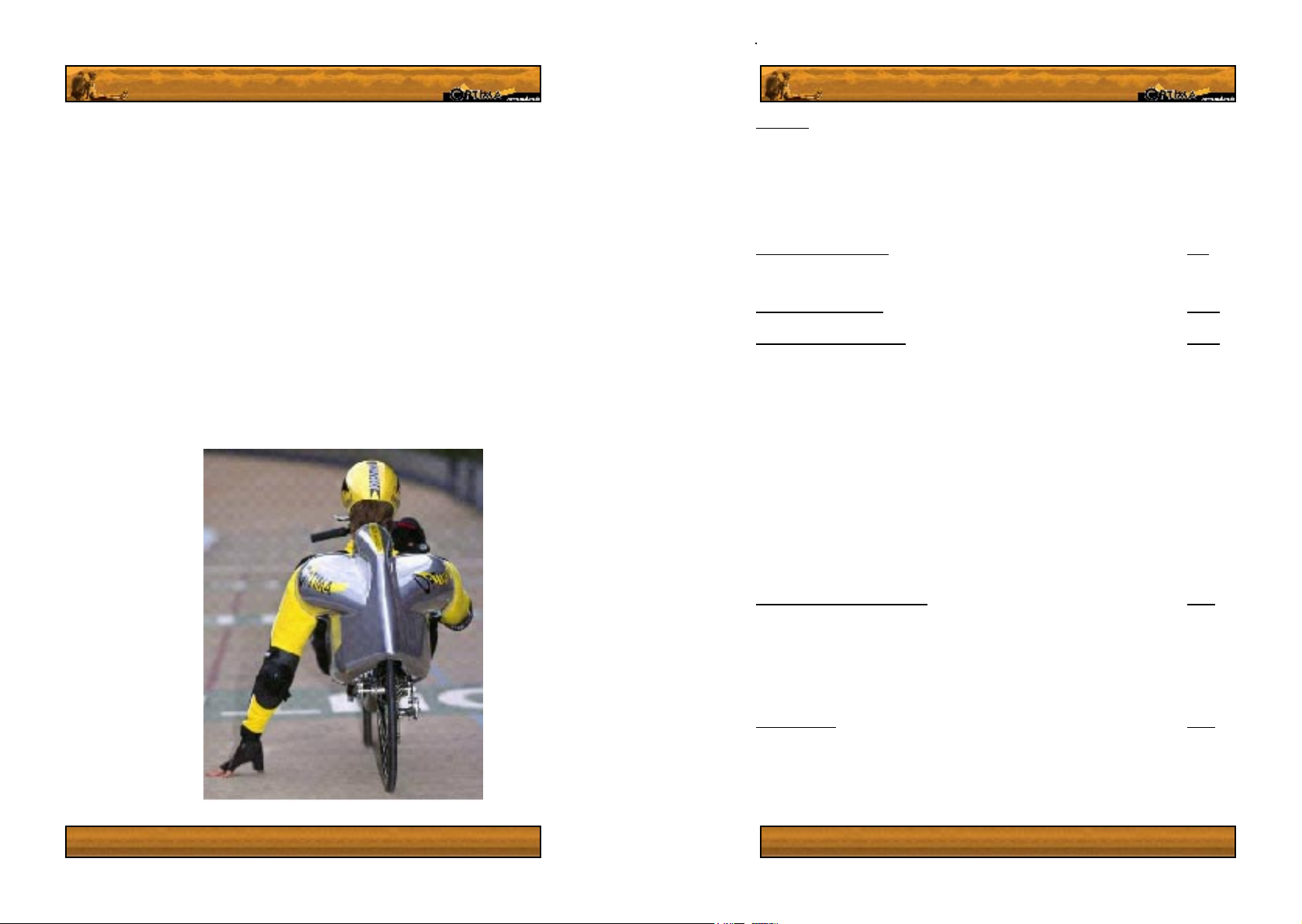
15.Mounting an aerodynamic fairing (Baron
Option)
A correctly installed fairing will reduce
your wind resistance by 10%, giving
you a competitive edge or that extra
bit of range on a ride. Follow these
instructions carefully and you will look
back – but only to see all the people
you’ve passed! A fairing kit can be
or der ed fr om an y offic ial Opti m a
representative and includes a Fairing,
bolts, spacers, a support arch and a
seat attachment plate.
The rst step in installing a fairing is
to put your seat all the way back, or to the position you wish to keep it in once the cowling is
installed. (The fairing will not t properly if the seat is more than half way upright.)
Now nd the included
templa te for the cutou t fo r th e wh eel
an d de rai l leu r on
the under side o f the
fairing, shaped like g
19.1. Make double and
triple sure to align the template properly, with the side marked derailleur side, on the correct
side of the fairing! (All you need to look for is ‘inside template side’ When this text is facing
YOU, the side facing down is the side described in the text.) Read the last sentence between
brackets again, because if you mess up here you can’t go back a step!!!
Tip: It is important that the fairing ts you like a glove: any
openings will effectively turn your fairing into a parachute
giving the opposite effect to what you want! Ask your optima
representative for hints and tips if you are uncertain of
anything.
18
19
Page 15

You will need one of two tools to cut the form out: a Jig saw or a tin cutter. If you don’t have
either of these tools we suggest you buy or rent one. If you use a jig saw, you must use a
special breglass saw on it, or the polyester of the fairing will spit and crack from the vibrations
created by cutting the fairing. This may all cost more, but it will cost less than ordering a new
fairing and the results will be much more satisfying in the long run. You will also need a pair of
safety glasses, gloves and preferably a long sleeve top and
long pants: Polyester shards are sharp and when they get
into your skin, they can cause a rash and irritation that could
last for about 10 days. Not protecting yourself whilst working
is foolish, and the chances are high you will wish you had
followed these guidelines after working if you don’t.
Fig 20.1 Jig saw & tin cutter
Be sure to nd one of these: a composite / bre glass saw blade
Once you have aligned the template correctly, trace the shape of
the template onto the shell and remove the template. Now get the
tin cutter or saw with the breglass cutting blade and cut away. You
may need to trim the form slightly to get a good t. Again, make sure
you use the special bre glass sawblade if you use a jig saw.
Now mount the rear fairing arch to the holes near the rear dropouts
on the frame, making sure to place a spacer between both the bolt
and arch, and arch and frame. Check that the bolt on the right hand
(derailleur and cogset) side does not scrape against the cassette
or interfere with shifting in any way. Also make sure that the arch
is well centred over the rear wheel. Remove and bend the arch if it
is not properly centred.
Drill one hole in the back of your seat using a 6mm drill bit,
approximately 5cm (2 inches) from the top of the seat, along its centreline.
Now that you have your drill handy, proceed to drill a hole in the top of the
fairing, approximately 32cm (12.5 in) from the seat side of the top ridge of
the shell. Use this hole to attach the fairing to the rear fairing support arch,
using the nut, washer, rubber spacer and low prole bolt provided. Place
the rubber spacer between the fairing and the top of the wheel arch. (See
g 20.2) All connections between the cowling and xture points should use
the included rubber spacers, between the inner side of the shell and the
xation point. Always place a rubber spacer between objects to be connected
to the fairing and the fairing itself.
Fig 20.2
Make sure you put your seat all the way back again, attach the cushion to the seat, and sit
down on the bike. If anyone else is round now would be a good time to ask for a little help.
Fix the seat attachment plate to the seat using the included rubber spacers and washers.
The longer arm of the seat attachment plate should be bolted to the hole you drilled in the
seat. Swing the cowling, now attached to its arch, down onto the plate, and start adjusting
the cowlings vertical and horizontal position by moving the seat plate up and down. Set
up the height and horizontal position of the fairing so that it ts ush to your shoulders just
behind their peak, making sure the t as close as it possibly can be. Make sure the seat
cushion is on the seat during this adjustment, otherwise you will be setting the fairing up too
low and it will be less comfortable and less effective.
Once you have found a comfortable position, (nd someone to help you
here if possible) mark the position that the hole for the bolt is against
the underside of the fairing, using a sharp implement or paint marker (g
21.2). You will need to reach you hand back up inside the cowling to do
this. Make sure the upper bolt is tightly fastened so that the attachment
plate doesn’t move. Now ip the cowling back and use a sharp implement
or a paint marker to mark one of the lower bolt hole on the seat plate’s
position against the seat. Drill a hole in both the cowling and the position
you marked on the seat, and fasten both points using the bolts and rubber
spacers provided. Drill the second hole you marked in the base of the
seat now and fasten the top plate properly.
Now that you have the fairing xed to the wheel arch and seat, it is time to drill and x it to
the bottom of the seat. Do this by aligning the lower arms of the fairing to the underside of
the seat and tape the bottom of the fairing to the seat securely making sure that the wheel
does not scrape against the back end of the fairing in doing so. Now drill a hole through
both the fairing and the seat from the bottom up (g 21.3). Attach the lower sides to the seat
using the low prole bolts, rubber spacer and bolts provided. You may now need to trim the
fairing to allow wheel clearance (g 21.1).
That’s it – your aerodynamic fairing is installed!
20
21
Page 16

Riding A Recumbent Bicycle
Before you ride
Before you take your beast out on the streets, take a moment on your bike to get used to the
new seating position and point of view that your Optima provides. Remember that in such a low
position, automobile drivers may not see you! For this reason we urge you to please exercise
caution whilst riding in trafc! Do not overtake in corners, this is extremely dangerous. Optima
strongly advises you to consider installing a (kiddy bike) ag on your bike if you ride in trafc
often, as this will increase your visibility to other road users signicantly.
Once you are used to riding in the recumbent position we advise that you use a ‘clipless’ pedal
system. These pedals can take a little while to get used to, but they will allow for much more
comfortable riding and result in less leg fatigue, as it takes more effort to keep your feet on the
pedals of a recumbent than a normal bicycle!
For your convenience and safety please make sure that the Bicycle ts you properly and
that you have followed all instructions for assembly as shown in the chapter ‘Setting up your
Bicycle’ before riding.
Short pre-ride checklist.
Brakes
Pull each brake lever to make sure there is no stickiness and that the brakes are properly
centered and engage the rims or disk properly, without scufng the tires. Check that they can
exert enough pressure to stop the bike. If your brakes are too tight or loose, adjustments should
be made. Please refer to the original manufacturers manuals, enclosed in the information
package and to the troubleshooting section of this manual.
Quick Release Levers
Please ensure that all wheels are securely and properly fastened before stepping on the bike.
Check that the quick release levers are rmly in their closed positions (see gures 6.2 & 6.3).
Failure to do so could result in a serious accident and injury.
Tires and wheels
Ensure that your tires are properly inated and that the wheels run true between your forks and
frame. Gas station pumps inate tires very rapidly, but the pressure gauges may be inaccurate.
We suggest you inate your tires using a hand pump and an appropriate pressure gauge to
read the pressure7. Grasp each wheel rmly and try to move it side to side. There should be
no noticeable play. If there is excessive play, ensure you have tightened the hubs before riding,
as this play may cause braking malfunction.
Seat
Ensure that your seat is securely fastened to the frame before mounting your recumbent bicycle.
See section 6, page 14: ‘tting seat and rack’ for more details.
Operating the gear changing systems.
Optima bicycles are supplied with three main types of gear shifting systems, Shimano trigger
shifters, SRAM twist shifters and Shimano bar end shifters. Each of these systems has it’s own
merits, and the choice for either comes down to nothing more than personal preference. To shift
twist shifters, twist the grip. To shift Shimano shifters, pull the trigger with your pointer or push
the lever with your thumb. To shift the bar-end levers, bend them forwards and backwards.
The right hand gearshift activator operates the rear derailleur; the left hand operates the front
derailleur. You must be pedalling to operate derailleur gear shifters.
Pushing Shimano thumblevers will generally push the chain to a larger cog and pulling the
trigger will move the chain to a smaller cog. Twisting gripshift grips downwards will generally
move the chain into a larger cog, and forwards back to smaller cogs. Pushing barend shifters
down shifts to larger cogs, pulling them back up goes to smaller ones. Generally the direction
with the most resistance is moving to a larger cog.
Caution! Do not shift derailleurs when you are standing still,
or backpedal whilst shifting. This may damage your shifting
system or lead to a fall.
Hub gears will work whilst pedaling or whilst standing still, but generally weigh more than
derailleur systems and are easier to maintain. Derailleur shifters are lighter and more easily
serviced, but are more open to the elements than a hub geared system.
If you want to shift into a harder gear at the front (Left) you will have push the derailleur to a
larger cog. To go to a faster gear in the rear (right), you will need to shift to a smaller cog. Whilst
this is at rst confusing, it will in time become second nature. As far as the position of the chain
on the cog goes; the closer the chain is to the centerline of the bike, the easier the bike is to
pedal and the slower you go. The further out it gets, the harder it is to pedal and the faster you
will go. Regard the front cogs as three speed ranges, with the rear allowing adjustment of this
range. Major speed changes will use the front derailleur. Smaller ones will use the rear.
Moving the chain towards the centerline of the bike is called ‘downshifting’ and moving it away
from the centerline is called ‘upshifting’
Tip: It is best not to put the chain into both small sprockets.
Riding in this gear combination could damage the rear
derailleur and will lead to irritating ‘chain slap’ noise, as
well as increased chances of the chain falling off the front
chainwheels
7
Please contact your bicycle dealer for an appropriate pressure gauge or pump.
22
23
Page 17

The First Ride
Warning! Take it easy when riding your bike for the rst 2
months. Riding a recumbent hard straight away will easily
overload your knees, and there is nothing worse than having a
new bike… and being unable to ride it!
Fig
24.1
Now that you have checked the bicycles basic mechanisms, go out onto a quiet street or
alley, away from trafc and take your rst spin on the bike. So… how do you ride one of these
things? Just set your eyes on the horizon, and GO! Starting for the rst time on a recumbent
can be a hairy experience, but you will be surprised just how fast you get used to riding on
your new bike. Riding a recumbent for the rst time is all about commitment. In the words of
a well-known shoe manufacturer, Just do it!
The basic skills and feelings are exactly the same as on a traditional bike, just now you feel
like you are riding on a couch! We strongly advise that you wear a helmet if helmets are
not already compulsory for cyclists in the country where you live.
Put your preferred leg on the upper pedal, bent and ready to push as hard as you can. Just like
on a normal bike, the faster you go on a recumbent the easier it is to stay upright. ‘Just testing’
your bike slowly will generally lead to you not even being able to take your other foot off the
ground. This may require a little courage – but it is denitely courage that will be rewarded!
Relax your arms and body – a tense body makes even a normal bike hard to ride. Now that
you have the foot of your preferred leg on the pedal and other holding you upright (g. 24.1,
A), you will need to push rmly on that pedal. Don’t look around you and decide where you
will fall – that is setting yourself up for failure. Look into the distance, loosen up, (you should
be able to steer with your ngertips) put all your weight on the seat, swallow your adrenaline
and go! Once you are moving, quickly, yet smoothly, bring your other leg up from the ground
(B) and put it on the other pedal ready to deliver the second power stroke(C). It may take a
few tries to build up the courage to do this, but soon we will be able to say ‘Congratulations!
You are now riding your Optima!’
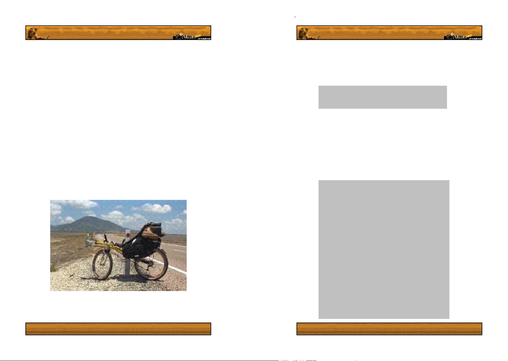
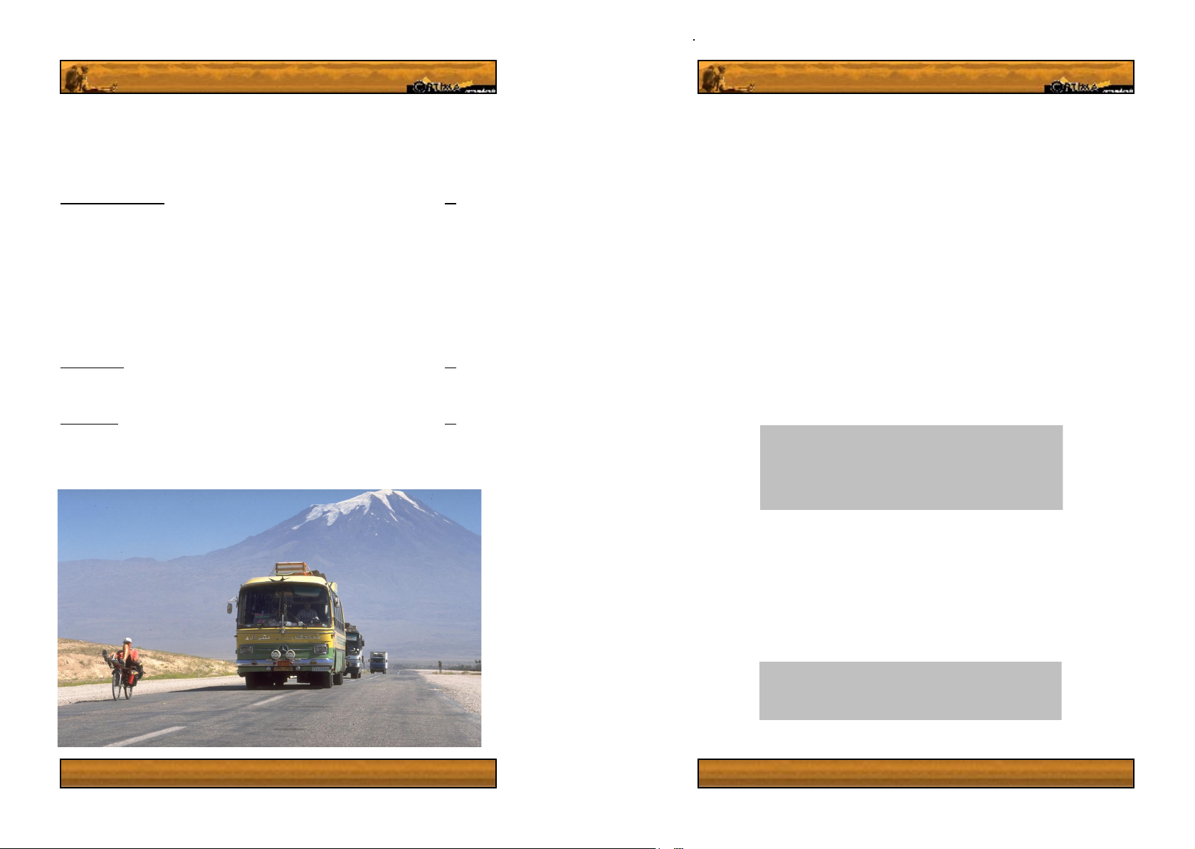
Travelling on your recumbent
Never thought of yourself as one to go on a bicycle holiday? Or maybe you have always
dreamed of a bicycle holiday? Optima bicycles are more than suited to travel on; almost all
Optima recumbents can be tted with bicycle pannier racks and special carrying bags to allow
for luggage transportation. You cannot however t any old bicycle rack to an Optima, you will
need to order the specially made Optima racks. These racks have been designed to carry
loads of up to 20 Kg on the Stinger and Baron, and 50Kg on all other models. Remember to
keep the weight as low as possible when packing your bike bags, as top-heavy bags will raise
the center of gravity and negatively inuence your bikes handling. Single wheeled baggage
trailers will have a greater inuence on the handling of your recumbent than a normal bike.
Be sure to pack them with the center of gravity as low as possible. Remember that loading
your bike will mean having to change suspension settings or even replacing the spring. (See
setting up your bicycle: suspension).
Please contact the dealer you purchased your Optima from for more details about bags and
racks .
Tip: Remember to shift to the lowest gear before you stop,
especially when you’re carrying extra luggage on the bike
Comfort and quality accessories for your
recumbent.
24
Optima manufactures a number of accessories for the improvement
of cycling comfort which can be ordered at any time from any sales
point. These accessories are, amongst others, a headrest, soft
handlebar grips, seat covers, a tailbox with luggage compartment
for the stinger and an adjustable stem for above steering models.
All these accessories are made of high quality durable materials,
are easy to install, and add to both the comfort and looks of your
recumbent.
The headrest is adjustable in height, with a hygienic breathing cover
which can easily be removed for machine washing. This headrest
is made with quality stainless steel rails and low prole bolts that
25
Page 18

Optima seat covers are made from the same
dur able and hygienic machine washable
material as the headrest cover, fitting all
standard sized optima seats cushions. These
covers look great and will make your cushion
and clothes last much longer.
Another handy option, exclusively designed
for the stinger, is the aerodynamic luggage
tail box. This luggage carrying fairing
at tac hes simp ly and se cur ely to the
integrated r ac k and upper seat a rc h,
giv i n g you a dry and secure space to carry your
th i n gs as well as an aerodynamic advantage,
all in one attractive unit. All you need to
do to install it is place it on the rack, drill through
the rack and tailbox at two points and fasten the
included bolts.
Maintenance
To keep your Optima working optimally you will need to carry out periodic maintenance. This
chapter outlines necessary periodic control and maintenance. We strongly advise you order
the parts listed in the ‘Accessories’ section of this manual from Optima or one of Optima’s
dealers only. This is for your own safety, to ensure you get the right parts.
Keeping your recumbent bicycle properly maintained is very important. Use the following outline
as a guide for repair and maintenance intervals. Many of these tasks are easy to do oneself,
but we recommend that you let an expert do the more challenging work (Working on hydraulic
brakes, truing buckled wheels, etc.). If you have any questions about how best to maintain
your bicycle, please feel free to contact your Optima dealer or Optima’s headquarters in the
Netherlands. (Address can be found in the last chapter of this book; ‘resources’.)
Certain parts such as the spokes and cables will ‘set in’ after the rst few rides, and related
systems may require some adjustment to maintain optimal functionality.
This maintenance schedule is based on normal usage. If you ride your bike more than average
or in adverse conditions, you may want to go over your recumbent more often than the manual
suggests. (carry out a quarterly check every month, for example) If any part malfunctions or
seems to be broken, immediately adjust or repair it yourself, or seek the help of a professional.
Do not ride a bicycle that is not functioning properly.
An e xot ic ac ces s ory f rom o pti ma is t he
ca rbo n f ibr e sea t , wei ghi n g in at a m ere
675 grams, com pared to around 1350 for a
standard medium seat. This seat is stiffer and
lighter than normal seats, giving a lighter bike
and more efcient cycling, not to mention the
beauty and allure of life’s most basic building
block, carbon.
26
27
Page 19

This maintenance schedule is based on normal usage. If you ride your bike more than average
or in adverse conditions, you may want to go over your recumbent more often than the manual
suggests. (carry out a quarterly check every month, for example) If any part malfunctions or
seems to be broken, immediately adjust or repair it yourself, or seek the help of a professional.
Do not ride a bicycle that is not functioning properly.
Recommended periodic maintenance
Each time you ride:
· Check your brakes work properly.
· Check that your gears work properly.
· Make a quick visual inspection of the bike to check for other faults.
· Check that quick release levers are securely fastened.
Weekly
· Clean off you bicycle and make a quick visual inspection of major parts
· Check tire pressure and general state of the tires
· Check brakes for correct function and adjust them if necessary.
· Adjust malfunctioning gears and lubricate the chain if dry.
Warning! Failure to follow these guidelines could allow
faults or badly adjusted components to go unnoticed, until a
resultant crash!
Quarterly checklist.
Brakes
· Check that the brake pads meet the disk or rim accurately and do not scuff the tires.
· Check your brake blocks for wear.
· Secure break mounting bolts.
Cables
· Check all cables for damage, kinks or wear. Replace as needed.
· Take the cables out of their housings and clean them, also checking for kinks in the wire
(replace if there are major kinks, as a cable may snap there if not replaced!
· Readjust gears and brakes to compensate for cable stretch.
Wheels
· Check hubs for excessive play or noise. Disassemble, re-lube and tighten the hub if you
encounter any of these.
· Check that your rims are true, and inspect them for ange denting and wear.
· Make sure that all the spokes are tight and equally loaded, check for kinks in the spokes.
Replace damaged spokes.
Tires and inner tubes
· Check tire pressure: Low tires will require more effort to keep rolling, and may be dangerous
in emergency maneuvers.
· Inspect tire tread and sidewalls for wear, splits and general integrity. Replace the tire
immediately if you can see the tire carcass or have any doubts on the state of the tire.
· Replace inner tubes with more than about 5 patches – these will generally leak slowly
anyway.
Derailleurs
· Check the sideways travel of the derailleurs, checking that the limiting screws keep the
derailleur away form the spokes and frame.
· Clean the rear derailleurs cogs and derailleur arm. Check cog bolts for proper tension.
· If the adjustment barrel on your derailleur and/ or shifters is signicantly screwed out,
its time to undo the cable bolt on the derailleur, screw the adjustment barrels in and
retighten the cable.
Drivetrain
· Inspect chain to ensure it is in a good state, with no seized links.
· Lubricate chain, clean beforehand if necessary. Don’t forget to clean the cogs if you clean
the chain! If you want to remove the chain, remember that all Optima bicycles come with
superlinks in the chains that can be taken apart with the hand.
· Inspect chainwheels and rear cassette, for wear and broken teeth. Worn teeth begin to
resemble shark ns.
· Check that the chainrings are true, and are properly tightened to the crank.
· Check that the rear cog cassette is securely fastened to the rear wheel. Tightening the
cassette requires a special tool.
· Check that the chain protection tubes are securely fastened to their ttings. A loose tube
may cause to chain to jump off the cogs unexpectedly or damage the derailleurs.
· Inspect and lube the chain rollers. Inspect the chain track; these are consumable products
which wear down, and will need replacement.
Headset
· Check for excess play or a ‘sandy’ feeling. Tighten or re-lubricate as necessary.
· Re-lubricate headset if the grease is dry or dirty.
· Check the lubrication of the Riders wheel xing / steering slave blocks.
Check the alignment of the handlebars
28 29
Page 20

Pedals, Cranks and Bottom bracket.
· Check pedals for cracks and other damage.
· Test the pedals for smoothness, and inspect lubrication. Clean and re-grease if
contaminated.
· Make sure that the pedals are securely fastened to the cranks.
· Make sure that the cranks are securely fastened to the bottom bracket axle.
· Ensure the bottom bracket is securely tightened inside the frame.
· Check the bottom bracket for smoothness and for excess play. If you have a cartridge
bottom bracket, replace when dysfunctional.
Suspension
· Dismount and clean rear shock absorber. Remove spring and depress shaft of the damper
into the shock body. Make sure this goes smoothly, and that there is no oil residue on
the Stanchion after its return.
· Clean and inspect suspension pivot points. Lightly grease shock absorber bushings.
Make sure not to use excessive lubricant, as this will attract dirt and may even increase
the rate of wear at the pivot points.
· Clean suspension fork sliders. Lubricate as advised in manufacturer ’s manual.
· Ensure that the suspension pivot points twist freely, without excessive play. This includes
the bushings on the shock absorbers.
Miscellaneous.
· Check tubes and frame for damage or damage to paint.
· Check that all nuts and bolts are fastened securely. Be careful not to over-tighten bolts.
Tools for maintenance
This section will cover which tools are necessary for maintenance of your Optima recumbent
bicycle, and will give a list of recommended extra tools. All fastenings on Optima bicycles have
standard metric sizes.
Allen Keys
· 2mm
· 2.5mm
· 3mm
· 4mm
· 5mm
· 6mm
· 8mm
· 10mm
(Rider wheel bolts)
Spanners/ Wrenches
· 8mm
· 9mm
· 10mm
· 13mm
· 15mm
Reccomended:
Chain Cleaner
Screwdrivers
Service tips
Adjustment of the hubs.
Both hubs on your bicycle must be correctly adjusted to minimize wear and tear. A hub that is
set too tightly or with too much play will wear faster than a correctly adjusted hub. The correct
play is approximately 0.3mm (0.012 in) at the rim. To readjust the hubs, remove them from the
bicycle. The front hubs can be adjusted from either side, but the rear hub may only be adjusted
on the left side (opposite to the cogs and freewheel assembly).
Hubs must be lubricated with grease on the bearings, with the area around the seals kept free
of grease, as this will attract dust and grit. Do not oil the bearings, as this will slowly erode
the grease lubrication.
Headset and front forks.
Due to the considerable stresses this area of your bicycle can undergo, correct adjustment is
important. Check that the headset in which the fork rests is free of play. We suggest you let
your Optima dealer deal with any excess play. If the headset cannot be adjusted such that no
play is present whilst offering no resistance to turning, please contact a local bike store. Check
regularly that the headset is fastened securely. For the Rider, ensure that the steel tube and
copper bushings on the steering slave blocks are properly greased.
Spoke tension
Spokes are an essential part of your bicycle and badly adjusted spokes will have a
negative inuence on the stability of your bicycle. Tensioning spokes is a specialized task,
which requires experience and insight. For this reason we advise you have tensioning done
by a professional. A few weeks after purchasing your bicycle we strongly recommend that you
have your spokes checked for tension
Warning! A loosely spoked wheel can result in your bike handling badly,
in normal and particularly in extreme conditions. Make sure your wheels
are well maintained by a properly qualied bicycle mechanic.
Bottom bracket and crank
The bottom bracket and cranks must be free of play. Check regularly that the chainwheel bolts
are securely tightened and that the cranks are securely fastened to the bottom bracket. Any
maintenance of the bottom bracket requires special tools and is best left to a professional
bicycle mechanic.
Gears
Your gears will need periodic adjustment to keep them working optimally. Cables stretch and
cable housings compress slightly after use, so adjustment may be necessary reasonably soon
after purchasing the bicycle. If you are uncertain how to adjust the gears, please refer to the
documentation of the original manufacturer, included in the information package. If you are
still hesitant, please take
your bike to a local bicycle store to be tuned up. Many Optima Bicycles require special extra
long gear shifting cables. Please contact Optima or your dealer for information.
30
31
Page 21

Storage tips
If you are not going to be using your recumbent for a while, it is imperative that it is stored
properly. Before storing your bike, be sure to clean and lubricate it, as a badly stored bicycle can
be difcult to get back to working order. Make sure not to get ANY grease on the disk brakes!!
If you do, you will have to clean it with proper disk brake cleaning uid. If any oil has got into
or onto the pads, you MUST throw them away and replace them for your own safety.
Store your bike in a dry, temperate, dark place. Hang the bike off the ground, and let the tires
down to about half pressure.
Tip: Avoid storing your bicycle near a generator or electric
motor, as these can produce ozone which can damage rubber
and may cause premature ageing of some protective paints on
your bicycle
Troubleshooting.
Problems? Troubles? Check to see whether you can nd the fault and x it, using this
section of the manual. If you see an asterix* you know the repair requires a special Optima
product, listed on pg 39.
The Following pages hold symptoms and possible causes with some handy tips to make
xing problems and general maintenance of your Optima recumbent bicycle much easier.
This troubleshooting section is by no means complete; If you wish to learn more about
bicycle maintenance we suggest that you contact a local bicycle dealer and ask about bike
maintenance books.
Suspension
The susupension does
not feel sensitive
enough over bumps
in the road
The suspension is too
soft; the bike bobs
around or bottoms
out.
The suspension is not
as sensitive as it used
to be
The syuspension fork
legs are covered in
oil, or oil is dripping
out of them
There is sideward
play in the rear
swingarm
The suspension is as
soft as it will go and
it just isnt working!
Wheels and tires
Every time i x a
at, the tire does at
again!
The tyre looses air
slowly
The tires wont sit correctly on the rim
The wheels are hard
to remove from and
replace in the frame.
The spring prelaod may be set too high,. Change this setting my twisting the
prelaod knobs on the forks (not present on all models) or by twisting the spring
on the rear shock so that the spring extends on the shaft.
Adjust the preaload so that the bike sags only slightly when you sit on it. Now
try riding again, adjusting the spring again as necessarry.
The fork stansions or pivot points may be dirty or require cleaning. If this does
not hepl, go to a bike store for assistance.
You have probably just burst a seal in the oil damping system. Take your bicycle to a good bike store to have the seal or cartrige replaced.
Check that all bolts on the swingarm are properly tightened. If this is not the
source of the problem please contact your dealer or optima for info on how to
proceed.
As strange as it sounds, you may beed to increase suspension preload to make
the system work properly. If this does not work, visit a good bike store and
ask tham; you may need a new spring in your suspension units that better suits
your weight.
Check the tube carefully to see if there are any other tiny holes. If the hole is
on the inside of the rim, you may have a spoke protuding into the tyre area. If
it is on the outside of the wheel, check the inside and outside of the tyre for any
embedded objects that could be causing your tyre to puncture. Also check the
state of the tyre tread: is ot worn out? this may account for many punctures.
You will need to check the tyre for tiny holes or valve problems. Do this by
submersing the inner tube in water and looking for bubbles. If you cant nd
any specicic leak, the tyre may be old and pourus, needing replacement. On
the trail, pump up the removed tyre and run it under your nose, you will feel
any air leaks in between your nose hairs.
Delfate the tyres and wiggle them on the rims to resettle them. When reinating
the tyre, stop pumping at 1 bar (15 psi) and spin the tyre to make sure it is well
set on the rim.
Have you unscrewed the quick release sufciently? Is the rear derailleur set to
the smallest cog? If the problem continues, please take your bicycle to a your
local dealer.
32
33
Page 22

Hubs
There is play inthe
hub when you push
sideways on the rim.
The hub does'nt roll
well and or feels
sandy
After a rear hub overhaul the derailleur
wont shift right.
The bike wont roll
properly (or if a trike,
it pulls to one side)
The front chainwheel
seems to bend while
p[edaling causing it
to scrape against the
derailleur.
There is creaking
sound when you pedal
You removed and
replaced the chinrings,
and now you can
barely shift gears
You bent the chainring
in a crash
You broke a tooth off
the chainring.
The hub may need tightening or readjustment. Adjusting hubs requires special
tools and can best be done by a qualied mechanic.
If you have recently overhauled the hub you may have over tightened the bearing cups. If not then you hub has probabl;y become contaminated with grit and
grind and will need to be dissasembled, cleaned and re-greased.
if bearings were replaced, the hubs balance may be slightly off. See the section
dreaillleur and greas on how to adjust the rear derailleur.
Your brakes may be dragging and incorrectly set up. Please refer to your braking equipmnt manual.
Check that the cranks are properly secured to the bottom bracket, and that all
chainrings are securely fastened to the cranks. If this doesnt help, have your
bottom bracket checked by a mechanic.
If you still encounter the problem, it may be that you are exerting too much
force on the fedaps: youll need to shift to an easier gear and pedal faster - if
you dont you will damage boith your bike and your knees.
listen carefully to see whether the sound is coming from your cranks or pedals. Check that your chainwheels are securely fastened to the frame. Check
that the cranks are tightened properly to the bottom bracket, and that the
bottom bracket is securely tightened in the frame. If the problem persisits,
try removing the cranks (special tool rquired) and greasing the bottom
bracket stubs.
You may have installed the chainrings the wrong way round. Check to
ensure thatthe shifting ramps and such are on the inside of the cranks. If this
si not the cause, readjust your front derailleur.
If the bend is severe, replace the chainring. If not too severe, get an adjustable spanner and close the jaws on the bent section of the chainring and bend
it true. If it brakes, that meant you needed to replace it anyway.
Its always best to replace the cahinring, but as a remporary x le down and
smoothen the remaining stub, and the chainring will function as usual.
Braking
One brake pad drags
agains the rim
The brakes bind
on the rim or dont
return snappily after
braking.
The brakes work
poorly and feel
squishy, you need to
pull the levers all the
way to the handlebars
for them to work.
The brake gets jerky
or grabs at one point
on the wheel
The brakes are too
tight, You cant get
them close enough to
put enough leverage
on them.
You hear a concerning metalic scraping
sound when braking:
braking performance
may have dropped.
I know what im
doing, yet I cant
properly bleed
the brakes on my
rider!
If you have V-brakes, you will need to adjust the spring tension by tightening
or loosening the spring adjustment bolts at the base of the brakes.
If your bike has Magura Rim Brakes, check whether the pads retract fully
into the slave cylinders. If they do not, remove the brake pads and clean out
the slave blocks and brake blocks with a toothbrush.\If the problem persisits
please take your bike to a qualied mechanic.
If your bike has Disks brakes, you may need to adjust the balance of the disk
using special disk brake spacers between the brake caliper and frame.
If you have cable brakes, remove the inner cables from the beake housings
and check for dirt and kinks. If the cabe is kinked, you will need to replace it
with a special tandem cable (standard cables are too short). If the cables are
undamaged, replace them with a thin coat of lubricant.
If you have hydraulic brakes, check the hydraulic lines for dents and pinching. We stongly advise having a qualied mechanic carry out any work on
hydraulic braking systems.
Check your pads and rim or disk for oil buildup. If you nd any oil on the
disk, thouroughly clean the disk rotor. Then remove and replace the brake
pads with new ones, being sure to dispose of the contaminated pads as these
are dangerous. If there is no oil, you may have air in your system. Please take
your bicycle to a sufciently qualied bicycle mechanic to bleed your brakes.
Inspect rim brake pads for wear and cosistency: old rubber can and will
degrade, reducing the rubber's ability to sloy you down.
Check the rim or disk for wear and trueness, or localised contamination.
Buckles in rims and diskscan cause braking irregularities. Replace, clean or
straighten the part as nececary.
If you have cable brakes, check to see whether the adjustment barrel is fully
screwed into the brake lever. If it is, thenv you may need to loosen the brake
cable at the brakes.
If you have self adjusting disk brakes, remove the wheel and use the yellow
disk brake spacer from Magura. If you dont have one, carefullt insert a at
head screwdriver between the pads and twist it to force them apart.
Your pads, Rim or Disk, are most likley severely work and the braking
surface is making contact with the metal casing of the brake pad. Stop using
the brake in question untill you can replace the pad.
Please contact Optima or your dealer for the special Rider bleeding kit.
34
35
Page 23

Derailleurs, Chain rollers and rear casette.
The shifting is not as
crisp as it used to be
When you stop
pedalling and coast,
the pedals want to
continue turning at the
chain bunches up
When riding there is a
slipping feeling in the
chain or a noise, as if
the chain is jumping
the cogs.
Pedaling feels rough
and the bike is hard to
propel even thought
the tires are pumped
up and the brakes do
not drag.
The derailleur refuses
to shift to the largest
or smallest cog.
The chain is always a)
black and grimy or b)
squeaky
The chain runs rought
and nothing iseem to
do will x it.
It has become
incresingly difcult
to change gears over
time
The rear derailleur
makes a 'grrrrr'sound
when in the large cogs
in the rear.
The derailleur may be slightly out of adjustment. You can try tweaking the
shifting my twisting the handlebar unit adjustment barrels, or that on the
rear derailleur. If this adjustment does not help, check that the casette is well
fastened to the freewheel body of the hub. If its loose, take your bicycle to your
dealer. If not, you may need to make a larger adjustment by loosening the bolt
on the derailleur and tighteningen it. Another idea would be to check the derailleur cables for grime, kinks or wear and replace as nescecary.
The freewheel mechanism of your hub has siezed up. Try spraying a light lubricant into it and allowing it to soak in, If this does not help, take your bicycle to
the nearest dealer for further help.
Is your derailleur properly adjusted? If it is and the problem occurs in one
particular gear, It may be your favorite gear and has become worn. Inspect the
chainwheel or cog in question. If the teeth resemble shark ns, it will need top
be replaced. If the skipping happens no matter what the gear, you most likley
have a frozen link. BAckpedal the gear system andd keep your eye on the chain
as it passes over the pulleys of the rear derailleur. the chain will most likey have
a stiff link, that once found will need to be grabbed at either side by pliers and
forced to bend to loosen it up. If there is no siezed link, visit your dealer.
Your chain has probaly become so dirty or dry that it is effecting the cycling
efciency. Clean and relube the chain. next check the rear derailleur pulleys
and chain rollers on the bike and lube or replace as nescecary. If the problem
continues, try overhauling your hubs.
If the cable is fully tensed (large sprocket) or fully slack (smalles sprocket) The
derailleur limitation screw may need to be adjusted. Please refer to the derailleur information, included i nthe info package. If not, you may need to play
with the derailleur adjustment barrels on the handlebars or rear derailleur.
You are probably using a) too heavy a lubricant or b) too light a lubricant for
your normal riding conditions. Please visit your dealer or local bike store and
ask for thier advice..
Your chain may be worn out or simply up to replacement. If you have just
replaced the rear casette or front chainrings, keep in mind that a drivetrain as a
whole wears together, and a new set of cogs may well not intermesh with the
old chain properly. Ask your dealer or local bike store
You may need to clean your cables, or even replace them. Remove the inner
cables, wipe them down and drop a little light grease into the outer cables, then
replace the inner cables.
You may need to adjust the derailleur height clearance bolt, found at the rear of
the derailleur, behind the frame nearby the attachment bolt. See the manufacturers manual.
Derailleurs, chain rollers and casette, contunued
The chain keeps on
falling off the smallest sprocket, at either
the front or rear.
The chain keeps
bunching up at one of
the rollers.
Pedals
The pedals squeak or
grind during riding
The pedals feel wobbly or rough
You are having
problems getting
into or out of click in
pedals.
Your pedals are
releasclick in ing you
unexpectedly.
The pedal wobbles
strangely whilst
pedalling
I cant get the pedals
onto the cranks! I
dont know why they
wont go on!
Are you riding on rough terrain with both derailleurs on the smallest cogs? Is
your chain set up to the correct length? See directions on page 16. If this is
not the case, you will need to screw in the lower derailleur travel limitation
screw. See the information pack from the derailleur manufacturer.
Is the chainline unobstructed? Maybe the chain retension bracket (present on
some pulleys) needs to be spun further around, in the same direction as the
chain is travelling.
You will most likley need to dissassemble the pedals and relubricate them.
The pedals may need replacement bearings. See whether the pedals can be
adjusted or tightened. Ask your dealer or local bike store for assistance.
Check that the spring tension is not set too high and that the cleats on your
shoes are properly aligned with the pedals. Read the manufacturers directions
or go to your dealer for help. Badly adjusted pedals can lead to severe knee, hip
and back problems.
You may need to tighten the spring tension on the pedals. If this is not it, the
cleat on your shoe may be worn out and will need replacing if this si the case.
Ask your dealer for advice.
Check that the cranks are properly tightened to the bottom bracket. Check
that the pedal is securely and properly fastened to the crank.If this is not the
problem, maybe you were recently involved in a crash which may have bent
the pedals? If so you may need to replace the pedal (axles). Do this promptly as
such occilations can cause bodily damage.
Are you threading the right pedal into the right and left pedal into the left
crank? Pedals have opposing threads on the spindles that prevent them from
loosening themselves during cycling. Otherwise check the state of the thred on
the pedals or crank.
36
37
Page 24

Forks and Headset
The threaded headset
will not stay in adjustment
The no thread headset
keeps loosening
A clunking noise comes
from the headset when i
brake or hit an obstacle
Miscellaneous
The seat creaks, wobbles or moves
The tiller stem swings
forward and backward
too easily
The chain protection
tubes have come loose
or have worn out
I own an trike and
it doesnt hadle well,
is unpredicatbel in corners and rolls badly
Theres a cracking
noise coming from the
frame
Make sure that there is a notched washer between the top and botom locknuts
of the headset. check that this washer cannot turn freely on the forks steerer
tube. Remove the stem and check that there is a small space between the top
of the fork steerer tube and the bottom of the top nut.
Remove the headset cap and stem. Check the two sections of the upper clamp
for stripped threads, and look to see how deep the starnut is in the forks steerer
tube. If it is within a centimetre (1/3 of an inch) of the top of the tube, get a
screwdriver and a hammer and knock it down around 1.5 cm (1/2 and inch).
You headest may be loose. Loosen the stem and tighten the bolt in the headset
cap. If this does not help, knock the starnut deeper as described above. If the
play only occurs in a certain range of steering angles, check that the headset is
xed properly in the frame
Remove the seat cushion and check that all bolts are tight. Next check that all
bolts holding the seat frames to the frame are tightened. Do not overtighten the
bolts on the seat as this will over stress it and lead to long term damage.
Try tightening the bolt at the base of the tiller arm. If this makes no difference,
The shims on your stem may be worn out. Contact your optima dealer for new
shims.
All tubes are fastened to the brackets using zip ties, and are easily reattached. If
the tubes have worn out, please contact optima and order new tubes. Have the
mesuerments of the old tubes handy to get the right lengths.
Your wheels are most likley out of allignemtn. Refer to pages 10 and 11 of this
manual.
Is the seat propely fastened to the frame and its brackets? Check the rear
suspension bushing, it may be too tight or need lubrication (grease). Otherwise
your headset may be causing the problem.
Optima bicycle models
38
39
Page 25

Permitted bicycle usage
The following table denes the use for which each bicycle will be covered under warranty. Failure
to follow these guidelines and a resultant failure will not be covered by the warranty.
Rough
N
N
N
N
N
N
N
Y
N
N
N
N
N
N
Stunt Riding
Y
Y
Y
Y
Y
Y
Y
Y
Y
Y
Y
Y
Y
Y
Daily Urban
20Kg
20Kg
N
50Kg
50Kg
50Kg
50Kg
N
N
50Kg
50Kg
50Kg
50Kg
20Kg
Bicycle Model
Roads
Commuting
Lynx
Orca
Rider
Children’s Bicycle / toy
Baron
Low Baron
Cobra
Condor
Dingo
Dolphin
Dragon
Gimmic
Hopper
Orynx
Stinger
Warranty permitted uses
Bike Holidays
Y
Y
Y
N
N
N
N
N
N
N
Y
N
N
N
Y
Y
Y
Y
Y
Y
Y
Y
N
N
Y
Y
Y
Y
N
N
N
Y
Y
Y
Y
N
N
Y
Y
Y
Y
N
Off road Riding
N
N
N
Y
Y
Y
Y
N
N
Y
Y
Y
Y
N
Road Racing
Downhill Racing
Light Recreation
N
N
N
N
Y
N
N
N
N
N
N
Y
N
N
N
N
N
N
N
N
N
N
N
N
N
N
N
N
N
N
N
Y
N
N
N
N
N
N
N
N
N
N
N
Touring
Baggage Rack (capacity)
Y
Y
Y
Y
Y
Y
N
Y
Y
Y
Y
Y
Y
Resources
Optima Factory
Optima Cycles
Industriestraat 3a
1976 CS IJmuiden
The Netherlands
Accessory list
To ensure your safety and maintain the quality of the parts on your bike, if you wish to upgrade
or replace worn parts we suggest that you order these parts only from Optima, your Optima
dealer or our representative. Certain parts on your bicycle are only available from Optima,
whereas other parts can be bought at most bike stores.
· Mudguards
· Baggage Racks (Optima bikes can only be equipped with Optima baggage racks. Failure
to use Optima racks will result in suspension malfunction and worse.)
· Bike luggage bags (See page 24, ‘Travelling with your recumbent’)
· Lighting systems (generator powered)
· Seats: S, M, L.
· Seat cushions (please include seat size in ordering information)
· Seat covers (please include seat size in ordering information)
· Chain tubes (Include bike model and your leg length in order)
· Extra long gear and braking cables (all above steering models need tandem cables for
the rear brake and derailleur)
· Recumbent Chain (standard chains are much too short)
· Wheels: 16, 20 and 26 inch
· Quality tires: 16, 20 and 26 inch sizes. (Quality small tires, generator suitable tires of
all sizes)
· Stems and Stem pivot shims
· Suspension pivots: bearings and bushings.
· Hydraulic and normal brake pads.
· Shock absorbers
· Suspension forks (for 20 and 26 inch wheel sizes)
· Rider brake bleeding kit
· 50 and 70mm chain rollers
· Low handlebar linkage system steering linkages, bushings and block
· Forks, linkage steering parts
tel: +31 (0)255 514 213
fax: +31 (0)255
email: info@optima-cycles.nl
40
Warning: Carrying out maintenance on your bike makes you
responsible for any work done! Make sure you know what you're
doing or seek the help of a qualied mechanic.
41
Page 26

Warranty
Terms and Conditions of Guarantee.
This section applies exclusively to French residents:
Optima states that this is a complete unique handcrafted frame built in the European community
and complying to the EU safety regulations concerning handcrafted bicycles, customised to
the individual users desires.
Optima’s craftsmanship can be displayed upon demand at its factory premises. None of
Optima’s bicycles are tested as series bikes. However optima assures the user that this bicycle
meets all safety requirements set for its frame and parts for strength and durability.
Fixation for lighting is available on all models: the customer is exclusively responsible for the
installation and maintenance, or absence of a lighting system which is approved of by the local
government or trafc safety authority.
The recumbent bicycle shall be referred to as ‘bicycle’
The manufacturer shall be referred to as ‘Optima’
The Bicycle owner shall be referred to as ‘end user’
Sales and maintenance representatives shall be referred to as
‘representative’
The Following guarantee is valid for Bicycles from Optima cycles, and only for bicycles bought
from ofcial dealers or from Optima itself. No second hand bicycles shall be covered by this
warranty. This warranty shall only cover materials, products and workmanship of the original
manufacturer, Optima Cycles V.O.F. This warranty only applies in countries where Optima has an
ofcial dealer or the country in which the customer bought the bicycle directly from Optima.
1)a) Optima guarantees that if any faults or damage occur to the frame as a result of material
or fabrication faults during the unlimited warranty period of 5 years for steel and 3 years for
aluminium, that the bicycle shall be replaced or repaired, at the sole disgression of Optima or
Optima’s representative. b) This guarantee will not cover the results normal wear and usage,
including fatigue. c) After 5 years for steel frames and 3 years for aluminium frames, a limited
warranty shall apply. d) In the event of replacement when the model or model version which is
under scrutiny is no longer in production, Optima will, at its sole disgression, replace the frame
with the most similar product available. e) replacement of parts or upgrading of componentry
which the bicycle was not designed to accommodate may void the warranty.
2) a) The Bicycle should be constructed to the factory export stage by an identied mechanic
or representative. If this is not the case, parts of the warranty can become nullied. b) If it can
be shown that an insufciently qualied person carried out signicant repairs on the bicycle,
and faults occur as a result thereof, Optima is freed of any liability and obligation to rectify
the damage.
3) a) Optima cannot be held responsible for any damage incurred during the transport and
delivery of the bicycle. b) Optima will under no circumstance be held responsible for delays
in delivery of the bicycle.
4) a) the obligations of Optima are limited to reparation or replacement of the bicycle or parts
thereof which are defective. b) Under no circumstance will Optima be held responsible for
damages or injury incurred to the rider or to any third party, or indirect costs as a consequence
of malfunction of the bicycle. c) Decisions regarding the replacement or reparation of a bicycle
or any part thereof, are exclusively left to Optima or Optima’s representative. d) Warranty
reparation man-hour costs will be billed to the bicycle owner.
5) a) Never use a bicycle that shows signs of malfunction. b) In case the bicycle shows any
signs of serious malfunction or damage, the end user must contact Optima or the representative
from whom the end user bought the bicycle. cd) Under no circumstance, shall this warranty
cover damage or injury which occurs as a result of incorrect installation, improper treatment
and use, intentional iniction of damage or unauthorized modications to the bicycle by or on
behalf of the end
42
43
Page 27

user, with the exception of modications which have been approved by Optima. d) Under
no circumstance will resultant problems from unattended malfunctioning of the bicycle be
compensated by Optima. e) In case of increased damage as a result of using a damaged
bicycle or end user negligence, which is deemed sufciently serious by Optima or Optima’s
representative, Optima will be released of any obligations.
6) a) The warranty begins on the day of transfer of ownership of the bicycle to the end user.
b) A completely lled in warranty card must be sent to Optima within one week of purchase of
the bicycle. If this is not done, parts of the warranty may be annulled. c) This warranty will not
be recognized and deemed invalid or if it can be proven that any fraud has been committed in
the form of any modications to any part of this warranty.
Service at delivery
Your delarer will have assembeled you bicycle out of the box, assuring that all bicycle
systems work correctly. The bicycle will be adjusted to t you properly and you will be
given instruction in the use of all the bicycles systems.
8) a) It is of great importance to follow the maintenance recommendations as described in the
user manual. b) Damage as a result of not following regular maintenance guidelines as described
in the manual shall not be covered by this warranty. c) Keeping of records of maintenance at
your dealer is of upmost importance. Make sure the dealer records work done in the service
record boxes in pages 44 to 47.
9) a) In case of unforeseen complications in reparations to the bicycle, the cost quote shall be
revised. b) Any concerns as to inconvenience or the costs of any reparation must immediately
be voiced to Optima or Optima’s representative, and must be resolved before repairs can
continue. c) If the end user does not communicate dissatisfaction in good time, Optima will
repair the bicycle to the satisfaction of its requirements. d) Optima will not be held responsible
for costs or events that transpire as a result of repairs or reparation duration. e) When necessary,
Optima or a representative will contact the end user to negotiate.
10) If sufcient reparations such that make the bicycle roadworthy again in accordance with
Optima’s specication for correct function, as deemed by Optima or Optima’s representative,
cannot be carried out in situ, the extra transport costs shall be billed to the end user. Article 3
applies to this transport.
11) This guarantee is only valid for the original owner of the bicycle, whose name is clearly
visible on both the product registration form and top of this warranty, whose name is in the
customer records of Optima. If the original papers cannot be produced and/ or there is cause
for suspicion, all costs for parts and work hours in reparation will be billed to the end user.
12) a) Complaints regarding the behavior or decisions of Optima or Optima’s representative
must be submitted by letter. The complaint and circumstance must be fully described in the
letter of dispute. b) Within one week of receiving your complaint Optima will contact you to
conrm the reception of your complaint.
13) A bicycle may not be covered by warranty if it can be shown that it has been used
in a manner other than intended by Optima. Refer to the table in the section ‘Bicycle use
categories’ an overview of the permitted uses of each bike model.
Dealers Stamp:
Comments and exchanged parts:
Service 2
This service is to be carried out no longer than 3 months or 500 km (300 mi) from the
time of purchase, to ensure all parts are working properly and make adjustmets adjust
for setting in of cables and spokes. This is an important service, not to be missed.
Dealers Stamp:
Comments and exchanged parts:
44
45
Page 28

Service 3
Service 5
Service 3
This service is to be carried out no longer than 6 months or 3000 km (2000 mi) from
the time of purchase.
Dealers Stamp:
Comments and exchanged parts:
Service 4
This service is to be carried out no longer than 12 months or 6000 km (4000 mi) from
the time of purchase.
This service is to be carried out no longer than 1.5 years or 9000km (5500 mi) from
the time of purchase.
Dealers Stamp:
Comments and exchanged parts:
Service 6
This service is to be carried out no longer than 2 years or 12’000 km (7500 mi) from
the time of purchase.
Dealers Stamp:
Comments and exchanged parts:
46
Dealers Stamp:
Comments and exchanged parts:
47
Page 29

Service 7
This service is to be carried out no longer than2.5 years or 15’000km (9000mi) from
the time of purchase.
This is your own copy of the warranty data. Please ll this page
in fully.
Model name:
Dealers Stamp:
Comments and exchanged parts:
Service 8
This service is to be carried out no longer than 3 years or 18’000km (11000mi) from
the time of purchase. This is the last registered service in this book. Please continnue
having you bicycle checked at 6 month, 3000 km (2000mi) intervals to ensure your
bicycle is kept in an optimal state.
Dealers Stamp:
Comments and exchanged parts:
Frame Number
Date of purchase (dd-mm-yyyy)
Purchased from:
Dealer modications at purchase
48
49
Page 30

Warranty Form
Please ll in this form completely.
This section comprises one (1) single side printed sheet, printed as a part of
the ofcial Owners Manual.
Please cut this page out and send it to Optima Cycles to activate
your guarantee. See reverse side for address.
WARRANTY FORM
Send this warranty form to:
Model name:
Frame Number:
Date of purchase (dd-mm-yyyy) , , 20
Purchased from:
Name of bicycle owner:
Street name and house number:
City/Town:
Post code: Province/ state:
Country:
Telephone:
50
Warranties department,
Optima Cycles V.O.F
Industriestraat 3a
1976 CS IJmuiden
The Netherlands
51
 Loading...