

Page 1

G200N SERIES NOTEBOOK PC
USER’S GUIDE
March 2004
Page 2

This page is intentionally left blank.
2
Page 3

CONTENTS
G200N SERIES NOTEBOOK PC
USER’S GUIDE ........................................................................................ 1
TAKING CARE OF YOUR NOTEBOOK PC ................................................... 5
1 BEFORE YOU START .............................................................................. 9
1-1 Making sure you have everything................................................... 9
1-2 Finding where everything is located ............................................ 10
2 GETTING STARTED ............................................................................... 17
2-1 Power Sources ............................................................................... 17
2-2 Display Panel .................................................................................. 20
2-3 Starting Your Notebook PC ...........................................................22
2-4 Status Display Indicators .............................................................. 24
2-5 Using the Keyboard ....................................................................... 27
2-6 Volume Control .............................................................................. 29
2-7 Power Management ....................................................................... 30
3 USING YOUR NOTEBOOK PC ............................................................... 33
3-1 Touchpad Pointing Device ............................................................33
3-2 Optical Drive ................................................................................... 37
3-3 PC Cards ........................................................................................ 43
3-4 Memory Upgrade Module .............................................................. 45
4 TROUBLESHOOTING ............................................................................ 49
4-1 Identifying the Problem.................................................................. 49
APPENDIX.................................................................................................... 51
Notebook Specifications ....................................................................... 51
WLAN Specifications ............................................................................. 52
3
Page 4

This page is intentionally left blank.
4
Page 5

TAKING CARE OF YOUR
NOTEBOOK PC
To prevent possible overheating of the computer’s processor, make sure you don’t block the openings provided for ventilation.
DO NOT place on uneven or unstable work surfaces.
DO NOT press or touch the display panel.
DO NOT use your notebook computer under harsh
conditions.
DO NOT place or drop objects on the computer and
DO NOT apply heavy pressure on it.
DO NOT subject the computer to magnetic fields.
5
Page 6
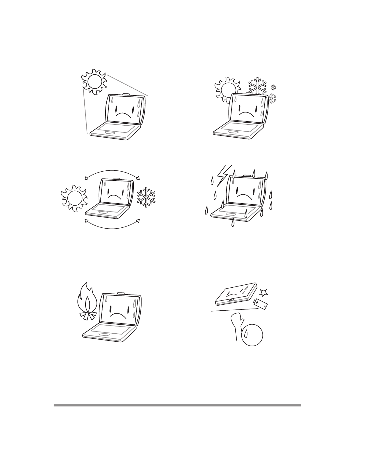
DO NOT expose to direct sunlight. DO NOT use or store in extreme temperatures.
Avoid sudden changes in temperature or humidity by
keeping it away fromA/C and heating vents.
DO NOT place near fire or other sources of heat. DO NOT tamper with the batteries. Keep them away
DO NOT expose the computer to rain or moisture.
from children.
6
Page 7

DO NOT expose to dust and/or corrosive chemicals. DO NOT slam your notebook shut and never pick up
or hold your notebook by the display.
DO NOT spray water or any other cleaning fluids
directly on the display.
If you are traveling with your computer, remember to
carry it as hand luggage. Do not check it in as baggage.
7
Page 8

This page is intentionally left blank.
8
Page 9
1 BEFORE YOU START
1-1 Making sure you have everything
When you receive your notebook PC, unpack it carefully, and check to make sure you
have all the items listed below. For a pre-configured model you should have the following:
• Notebook Computer
• Lithium ion battery, pre-installed
• AC adapter with AC power cord
• Phone/Modem (RJ-11) telephone cable
• Driver and Applications CD
• User Guide (this document)
Depending upon the configuration of your notebook, you may also need the following
items:
• DVD Application CD
• CD-RW Application CD
• DVD / CD-RW Combo Application CD
• DVD +RW Application CD
Once you have checked and confirmed that your notebook system is complete, read
through the following pages to learn about all of your notebook components.
9
Page 10
1. BEFORE YOU START
1-2 Finding where everything is located
1-2-1 OPENING THE DISPLAY PANEL
1. Slide the latch located at the top of the display panel to the right. This releases the
locking mechanism and raises the display slightly.
2. Lift the display backwards, being careful not to touch the screen, until it is at a
comfortable viewing angle.
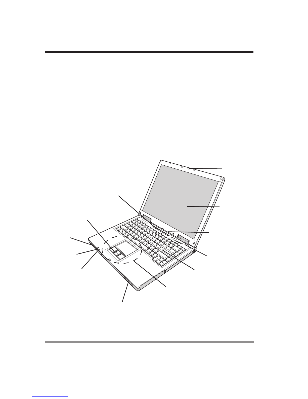
1-2-2 TOP AND FRONT COMPONENTS
The following is a brief description of your notebook’s top and front components.
Display Panel
Latch
Suspend/Resume/
Power On Button
10
Stereo
Speaker
Battery
Indicator
Scroll Button
Power
Indicator
Display Panel
Application
Panel
Status Display
Indicator
Keyboard
TouchPad Pointing Device
Stereo Speaker
Page 11

1. BEFORE YOU START
Display Panel Latch
The display panel latch locks and releases the display panel.
Display Panel
The display panel is a color LCD panel with back lighting for the display of text and
graphics. (See 2-2 Display Panel for more information.)
Application Panel
The Application Panel allows you to either launch your favorite applications or to use as
an optical drive when your unit is on.
Status Display Indicators
The Status display indicator lights correspond to specific components of your notebook.
(See suspend notebook activity without powering off, resume your notebook from
suspend mode, and power on your notebook when it has been shut down from Windows. (See Suspend/Resume/Power On Button in 2-3-1 Power On for more
information.)
Stereo Speakers
The built-in dual speakers allow for stereo sound.
Keyboard
A full-size keyboard with dedicated Windows keys. (See 2-5 Using the Keyboard
for more information.)
Touchpad Pointing Device
The Touchpad pointing device is a mouse-like cursor control with three buttons (left,
right, and scroll buttons). (See 3-1 Touchpad Pointing Device for more informa-
tion.)
Power/Battery Indicators
The power and battery LEDs on the front of the unit allow you to monitor power and
battery status while the system is closed.
11
Page 12
1. BEFORE YOU START
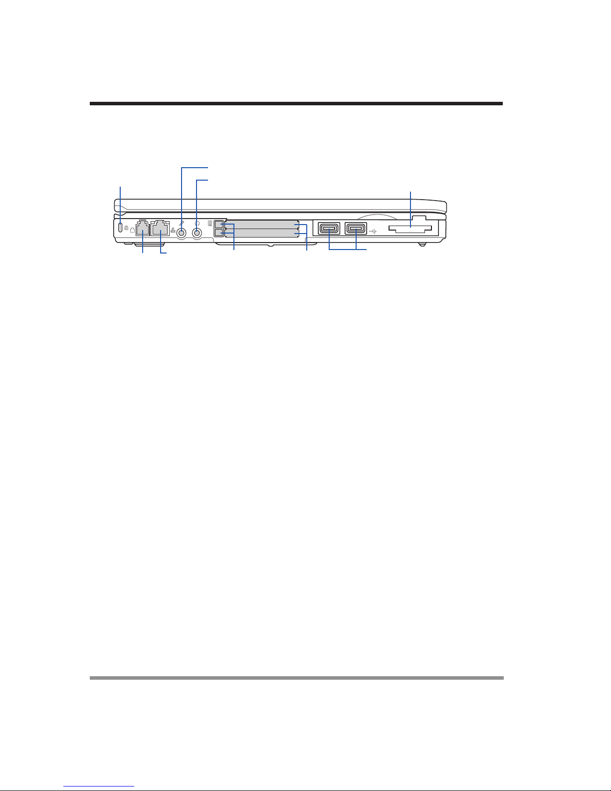
1-2-3 LEFT-SIDE PANEL COMPONENTS
The following is a brief description of your notebook’s left-side components.
Kensington
Lock Slot
Modem
Por t
(RJ-11)
Ethernet
Por t
(RJ-45)
Microphone Jack
Headphone Jack
PC Card
Eject Buttons
PC Card
Slots
Memory Card Reader
USB
Por ts
Anti-theft Lock Slot
The anti-theft lock slot allows you to attach an optional physical lock-down device.
Modem (RJ-11) Telephone Jack
The Modem (RJ-11) telephone jack is used to attach a telephone line to the internal
56K modem.
Microphone Jack
The microphone jack allows you to connect an external mono microphone.
PC Card Slot
The PC Card Slot allows you to install one Type II or Type III PC Card.
Memory Card Reader
The memory card reader offers the fastest and most convenient method to transfer
pictures, music and data between your notebook PC and flash-compatible devices such
as digital cameras, MP3 players, mobile phones, and PDAs.
Headphone Jack
The headphone jack allows you to connect headphones or external speakers with
amplifier.
LAN Jack (RJ-45)
The LAN jack is designed support a 10 Base-T or 100 Base-TX standard RJ-45 plug.
12
Page 13

1. BEFORE YOU START
1-2-4 RIGHT-SIDE PANEL COMPONENTS
The following is a brief description of your notebook’s right-side components.
Optical Drive
Eject Button
Lithium ion
Battery Bay
Optical
Drive
Emergency Optical Drive
Tray Release
Lithium ion Battery Bay
The internal battery pack can be removed for installation of a fully charged battery pack.
(See 2-1-3 Replacing the Battery for more information.)
Optical Drive
The optical drive allows you to play back a media disc. (See 3-2 Optical Drive for
more information.)
Optical Drive Eject Button
The Optical Drive Eject Button allows you to open the optical drive tray to remove or
install a DVD, CD-R, or CD-ROM. (See 3-2 Optical Drive for more information.)
Emergency Optical Drive Tray Release
The Emergency Optical Drive Tray Release allows you to open the optical drive tray
without powering on your notebook.
13
Page 14
1. BEFORE YOU START
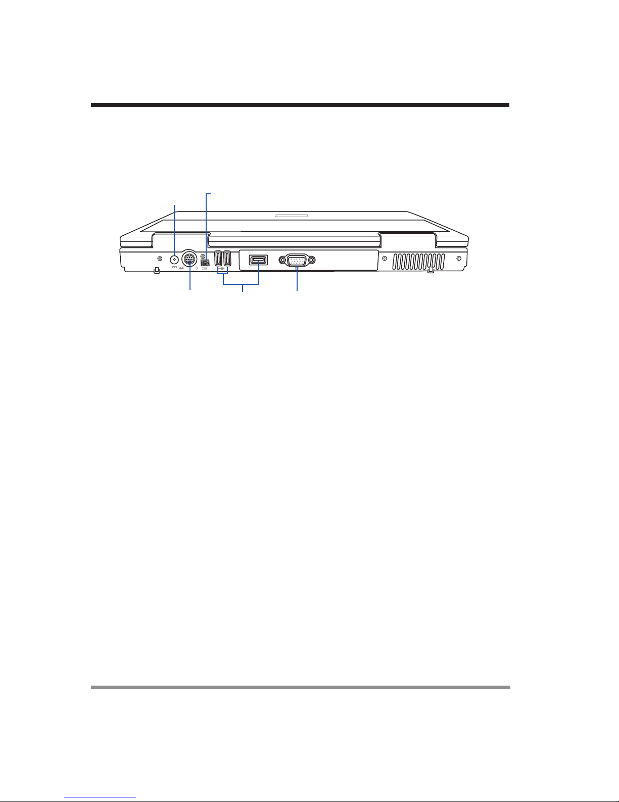
1-2-5 BACK PANEL COMPONENTS
The following is a brief description of your notebook’s back panel components.
Power
Adapter
Por t
PS/2
Por t
IEEE
1394
Por t
Por ts
USB
External
Monitor
Por t
DC Power Jack
The DC power jack allows you to plug in the AC adapter or the optional Auto/Airline
adapter to power your notebook and charge the internal Lithium ion battery.
PS/2 Port
The PS/2 port allows you to connect an external PS/2 keyboard, mouse or numeric
keypad.
IEEE 1394 Port
The 1394 port is used to connect between your and a peripheral such as a digital video
camera.
USB Ports
The three USB ports allow you to connect Universal Serial Bus devices.
External Monitor Port
The external monitor port allows you to connect an external monitor.
14
Page 15
1. BEFORE YOU START
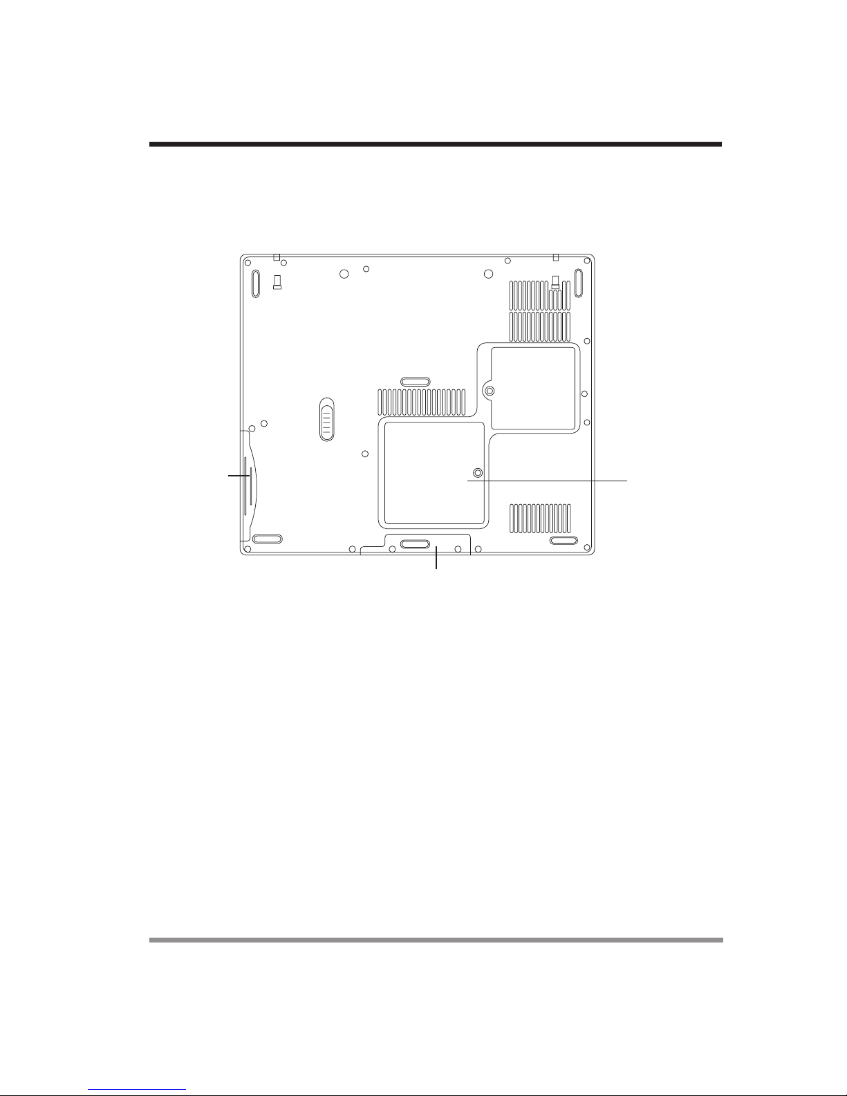
1-2-6 BOTTOM COMPONENTS
The following is a brief description of your notebook’s bottom panel components.
Main Unit and
Configuration Label
Lithium ion
Battery Bay
Hard Disk Drive Bay
Memory
Compartment
Main Unit and Configuration Label
The configuration label shows the model number and other information about your
notebook. In addition, the configuration portion of the label has the serial number and
manufacturer information that you will need to give your support representative. It
identifies the exact version of various components of your notebook.
15
Page 16

1. BEFORE YOU START
Lithium ion Battery Bay
The battery bay contains the internal Lithium ion battery. It can be opened for the
removal of the battery when stored over a long period of time or for swapping a discharged battery with a charged Lithium ion battery. (See 2-1-3 Replacing the Battery
for more information.)
Memory Compartment
The memory compartment contains the system RAM. The RAM can be expanded
according to the information contained in 3-4 Memory Upgrade Module.
16
Page 17

2 GETTING STARTED
2-1 Power Sources
Your notebook PC has two possible power sources: a primary Lithium ion battery or an
AC adapter.
2-1-1 CONNECTING THE POWER ADAPTERS
The AC adapter provides power for operating your notebook PC and charging the
batteries.
Connecting the AC Adapter
1. Plug the DC output cable into the DC power jack of your notebook PC.
2. Plug the AC adapter into an AC electrical outlet.
POINT
The Lithium ion battery is not charged upon purchase. Initially, you
will need to connect the AC adapter to use your notebook PC.
17
Page 18

2. GETTING STARTED
2-1-2 RECHARGING THE BATTERY
The Lithium ion battery is recharged internally using the AC adapter. To recharge the
battery make sure the battery that needs to be charged is installed in your notebook PC
and connect the AC adapter.
There is no memory effect on the Lithium ion battery, therefore you do not need to
discharge the battery completely before recharging. The charge times will be significantly
longer if your notebook PC is in use while the battery is charging. If you want to charge
the battery more quickly, put your notebook PC into Suspend mode, or turn it off while
the adapter is charging the battery. (See 2-7 Power Management for more information
on Suspend mode and shutdown procedure)
Low Battery State
When the battery is running low, a low battery notification message will appear. If you
do not respond to the low battery message, the battery will continue to discharge until it
is too low to operate. When this happens, your notebook PC will go into Suspend
mode. There is no guarantee that your data will be saved once the notebook reaches
this point.
CAUTION
Once your notebook PC goes into Dead Battery Suspend mode you will be unable to
resume operation until you provide a source of power either from an adapter, or a
charged battery. Once you have provided power, you will need to press the Suspend/
Resume button to resume operation. In the Dead Battery Suspend mode, your data can
be maintained for some time, but if a power source is not provided promptly, the Power
indicator will stop flashing and go out, meaning that you have lost the data that was not
stored. Once you provide power, you can continue to use your notebook PC while an
adapter is charging the battery.
To protect your notebook PC from damage, use only the power
adapter that came with the notebook PC because each power
adapter has its own power output rating.
Shorted Battery
The Status Indicator panel uses a symbol inside the battery outline of the Battery Level
indicator to display the operating level available in that battery. If this display shows a
Shorted Battery, it means that the battery is damaged and must be replaced so it does
not damage any other parts of your notebook PC.
18
Page 19

2. GETTING STARTED
2-1-3 REPLACING THE BATTERY
With the purchase of an additional battery, you can have a fully charged spare to swap
with one that is not charged.
1. Have a charged battery ready to install.
2. Shut down your notebook PC and disconnect the AC adapter.
3. Slide the battery release latch while pulling the battery from the bay.
4. Remove the battery from the bay.
5. Slide the new battery into the bay. The pins will automatically align with the connec-
tor.
6. Press the battery in until the battery release latch snaps into place.
7. Plug in the AC adapter and turn the power on.
POINT
If the Lithium ion battery connector is not fully seated, you may
not be able to use your notebook PC or charge your battery.
Battery Latch
19
Page 20

2. GETTING STARTED
2-2 Display Panel
Your notebook PC contains a display panel that is backlit for easier viewing in bright
environments and maintains top resolution through the use of active-matrix technology.
2-2-1 OPENING THE DISPLAY PANEL
1. Slide the latch located at the top of the display panel to the right. This releases the
locking mechanism and raises the display slightly.
2. Lift the display backwards, being careful not to touch the screen, until it is at a
comfortable viewing angle.
Display
Panel
Latch
20
Page 21

2. GETTING STARTED
2-2-2 ADJUSTING DISPLAY PANEL BRIGHTNESS
Once you have turned on your notebook PC, you may want to adjust the brightness
level of the screen to a more comfortable viewing level. There are two ways to adjust
the brightness, keyboard and power management utility.
POINT
The higher the brightness level, the more power the notebook PC
will consume and the faster your batteries will discharge. For
maximum battery life, set the brightness to as low a level as
possible.
Keyboard
Adjusting the brightness using the keyboard changes the setting only temporarily.
• [FN+F6]: Pressing repeatedly will lower the brightness of your display.
• [FN+F7]: Pressing repeatedly will increase the brightness of the display.
POINT
If using AC power, your brightness setting is set to its highest level
by default. If using battery power, your brightness settings is set to
approximately mid-level by default.
2-2-3 CLOSING THE DISPLAY PANEL
1. Holding the edge of your display panel, pull it forward until it is flush with the body
of your notebook.
2. Push down until you hear a click. This will engage the locking mechanism and
prevent your display panel from opening unexpectedly.
21
Page 22

2. GETTING STARTED
2-3 Starting Your Notebook PC
2-3-1 POWER ON
Suspend/Resume/Power On Button
The suspend/resume/power on switch is used to turn on your notebook from its off
state. Once you have connected your AC adapter or charged the internal Lithium ion
battery, you can power on your notebook.
POINT
Press the suspend/resume/on button located above the keyboard to turn on your
notebook. If you need to take an extended break, you may either place it in Suspend
mode (See 2-7-2 Suspend Mode for more information) or turn it off directly (See 2-
7-6 Power Off for more information).
CAUTION
When you power on your notebook, it will perform a Power On Self Test (POST) to
check the internal parts and configuration for correct functionality. If a fault is found,
your notebook PC will emit an audio warning and/or an error message will be displayed.
Depending on the nature of the problem, you may be able to continue by starting the
operating system or by entering the BIOS setup utility and revising the settings.
When you turn on your notebook be sure you have a power
source. This means that either the battery is installed and charged,
or that the AC adapter is connected with AC power.
Do not carry your notebook around with the power on or subject
it to shocks or vibration, as you risk damaging your notebook.
After satisfactory completion of the Power On Self Test (POST), your notebook will
load your operating system.
CAUTION
22
Never turn off your notebook during the Power On Self Test
(POST) or an unrecoverable error may occur.
Page 23

2. GETTING STARTED
2-3-2 BOOT SEQUENCE
The procedure for starting-up your notebook is termed the Bootup sequence and
involves your notebook’s BIOS. When your notebook is turned on the for the first
time, the main system memory is empty, and it needs to find instructions to start up your
notebook. This information is stored in the BIOS program. Each time you power on or
restart your notebook, it goes through a boot sequence which displays a flash screen
until your operating system is loaded. During booting, your notebook is performing a
standard boot sequence including a Power On Self Test (POST). When the boot
sequence is completed without a failure and without a request for the BIOS Setup
Utility, the system displays the operating system’s opening screen.
The boot sequence is executed when:
• You turn on the power to your notebook.
• You restart your notebook from the Windows Shut Down dialog box.
• The software initiates a system restart. Example: When you install a new application.
2-3-3 BIOS SETUP UTILITY
The BIOS Setup Utility is a program that sets up the operating environment for your
notebook. Your BIOS is set at the factory for normal operating conditions, therefore
there is no need to set or change the BIOS environment to operate your notebook.
The BIOS Setup Utility configures:
• Device control feature parameters, such as changing I/O addresses and boot de-
vices.
• System Data Security feature parameters, such as passwords.
Entering the BIOS Setup Utility
To enter the BIOS Setup Utility, do the following:
1. Turn on or restart your notebook.
2. Press the [F2] key once the flash screen appears on the screen. This will open the
main menu of the BIOS Setup Utility with the current settings displayed.
3. Press the [RIGHT ARROW] or [LEFT ARROW] key to scroll through the other
setup menus to review or alter the current settings.
23
Page 24

2. GETTING STARTED
2-4 Status Display Indicators
The Status Display Indicator LEDs correspond to specific components of your notebook. These lights (when visible) tell you that those components are operating. There
are two additional lights on the front edge of the system to indicate battery and power
states.
Battery
Indicator
Powe r
Indicator
CapLk
A 1
NumLk
ScrLk
S
Floppy
Drive
Access
Hard
Drive
Access
Optical
Drive
Access
2-4-1 POWER INDICATOR
The Power indicator symbol states whether your system is powered on. It has several
different states, each state indicates your notebook’s operating mode.
• Steady On: This means that there is power to your notebook and that it is ready for
use.
• Flashing: This means that your notebook is in Suspend mode.
• Steady Off (not visible): This means that your system is either in Save-to-Disk
mode, or that your notebook has been turned off with the power switch.
If you are charging your battery, the Power indicatorsymbol will remain on even if your
notebook is shut off. The Power indicator symbol will also remain on if you have either
adapter connected and are shut down from Windows, but have not turned off the power
switch.
24
Page 25

2. GETTING STARTED
2-4-2 BATTERY INDICATOR
The Battery indicator tells you whether the primary Lithium ion battery is charging or
fully charged.
POINT
CAUTION
If there is no battery activity, the power adapters are not
connected, or the power switch is Off, the Battery indicator will
also be off.
Batteries subjected to shocks, vibration or extreme temperatures
can be permanently damaged.
2-4-3 OPTICAL DRIVE ACCESS INDICATOR
The Optical Drive Access indicator tells you that the optical drive drive is being accessed. If the Auto Insert Notification function is active, the indicator will flash periodically when your system is checking the optical drive drive. If the Auto Insert Notification
function is not active, the indicator will only flash when you access the optical drive
drive. The default setting is the Auto Insert Notification function active. (See 3-3-8 Auto
Insert Notification Function for more information.)
2-4-4 HARD DRIVE ACCESS INDICATOR
The Hard Drive Access indicator states whether your internal hard drive is being accessed.
2-4-5 FLOPPY DRIVE ACCESS INDICATOR
The Floppy Drive Access indicator states whether the internal floppy disk drive is being
accessed. This indicator will flash if your software tries to access a disk even if no floppy
disk drive is installed. (See 3-2 Internal Floppy Disk Drive for more information.)
25
Page 26

2. GETTING STARTED
2-4-6 NUMLK INDICATOR
The NumLk indicator states that the internal keyboard is set in ten-key numeric keypad
mode.
POINT
If you are using the optional external numerical keypad, pressing
the [NumLk] key will activate the external keypad. The indicator
will come on, however it will not change any of the functionality of
your keyboard keys.
2-4-7 CAPSLOCK INDICATOR
The CapsLock indicator states that your keyboard is set to type in all capital letters.
2-4-8 SCRLK INDICATOR
The ScrLk indicator states that your scroll lock is active.
S
26
Page 27

2. GETTING STARTED
2-5 Using the Keyboard
Your notebook has an integral 87-key keyboard. The keys perform all the standard
functions of a 101-key keyboard, including the Windows keys and other special function
keys. This section describes the following keys.
• Numeric keypad
• Cursor keys
• Function keys
• Windows keys
ESC
F1 F2 F3 F4 F5 F6 F7 F8 F9 F10 F11 F12
Z
Z
Z
~
!
@#
1234567890
Tab
Shift
A
Z
Start
Key
Caps
Lock
Fn
Key
$%
SDF GH JK L
XCVBNM
\
Function Keys
^
TREWQ
Y
&
789
Numeric
Keypad
54
1
0
Application
(
2
AltAltFn
Keys
Scr Lk Prt Sc
-
-
{
[]
:
"
;
-
?
/
+
+
=
CtrlCtrl
)
/
POIU
6
3
,
.
.
SysRq Break
Backspace
}
\
Enter
Shift
Cursor
Keys
2-5-1 NUMERIC KEYPAD
Certain keys on the keyboard perform dual functions as both standard character keys
and numeric keypad keys. NumLk can be activated by pressing the [NumLk] keys.
Turning off the NumLk feature is done the same way. Once this feature is activated you
can enter numerals 0 through 9, perform addition ( + ), subtraction ( - ), multiplication (
* ), or division ( / ), and enter decimal points ( . ) using the keys designated as ten-key
function keys. The keys in the numeric keypad are marked on the front edge of the key
to indicate their secondary functions.
PauseDeleteNum Lk Insert
Home
PgUp
PgDn
End
POINT
If you are using the optional external numerical keypad, pressing
the [NumLk] key will activate the external keypad. The indicator
will come on, however it will not change any of the functionality of
your keyboard keys.
27
Page 28

2. GETTING STARTED
2-5-2 WINDOWS KEYS
Your notebook has three Windows keys, consisting of two Start keys and an Application key. The two Start keys display the Start menu. This button functions the same as
your on-screen Start menu button. The Application key functions the same as your right
mouse button and displays shortcut menus for the selected item. (Please refer to your
Windows documentation for additional information regarding the Windows keys.)
2-5-3 CURSOR KEYS
The cursor keys are the four arrow keys on the keyboard which allow you to move the
cursor up, down, left and right in applications. In programs such as Windows Explorer, it
moves the “focus” (selects the next item up, down, left, or right).
2-5-4 FUNCTION KEYS
Your notebook PC has 12 function keys, F1 through F12. The functions assigned to
these keys differ for each application. You should refer to your software documentation
to find out how these keys are used.
The [FN] key provides extended functions for the notebook and is always used in
conjunction with another key.
• [FN+F3]: Pressing [F3] while holding [FN] will toggle the Audio Mute on and off.
• [FN+F5]: Pressing [F5] while holding [FN] allows you to toggle between video
compensation and no compensation. (Video compensation controls spacing on the
display. When it is enabled, displays with less than 800 x 600 pixel resolution will
still cover the entire screen.)
• [FN+F6]: Pressing [F6] repeatedly while holding [FN] will lower the brightness of
your display.
• [FN+F7]: Pressing [F7] repeatedly while holding [FN] will increase the brightness of
the display.
• [FN+F8]: Pressing [F8] repeatedly while holding [FN] will decrease the volume of
your notebook PC.
• [FN+F9]: Pressing [F9] repeatedly while holding [FN] will increase the volume of
your notebook PC.
• [FN+F10]: Pressing [F10] while holding [FN] allows you to change your selection
of where to send your display video. Each time you press the combination of keys
you will step to the next choice. The choices, in order, are: built-in display panel
only, both built-in display panel and external monitor, or external monitor only.
28
Page 29

2. GETTING STARTED
2-6 Volume Control
Your notebook has multiple volumecontrols which interact with each other.
POINT
Any software that contains audio files will also contain a volume
control of its own. If you install an external audio device that has
an independent volume control, the hardware volume control and
the software volume control will interact with each other. It should
be noted that if you set your software volume to Off, you will
override the external volume control setting.
2-6-1 CONTROLLING THE VOLUME
• The volume can be controlled in several different ways:
• Volume can be set from within the Volume Control on the Taskbar.
• Volume can be controlled with the [F8] and [F9] functions keys. Pressing [F8]
repeatedly while holding [Fn] will decrease the volume of your notebook. Pressing
[F9] repeatedly while holding [Fn] will increase the volume of your notebook.
• Volume can be controlled by many volume controls that are set within individual
applications.
• Certain external audio devices you might connect to your system may have hard-
ware volume controls. Each source discussed above puts an upper limit on the
volume level that must then be followed by the other sources.
We recommend that you experiment with the various volume controls to discover the
optimal sound level.
29
Page 30

2. GETTING STARTED
2-7 Power Management
Your notebook has many options and features for conserving battery power. Some of
these features are automatic and need no user intervention. However, others depend on
the parameters you set to best suit your operating conditions.
2-7-1 SUSPEND/RESUME/POWER ON BUTTON
When your notebook is active, the Suspend/ Resume/Power On button can be used to
manually put your notebook into Suspend mode. Push the Suspend/Resume/Power On
button when your notebook is active, but not actively accessing anything, and immediately release the button. You will hear two short beeps and your system will enter
Suspend mode.
If your notebook is suspended, pushing the Suspend/Resume/Power On button will
return your notebook to active operation. You can tell whether or not your system is in
Suspend mode by looking at the Power icon on the Status LCD Panel. (See 2-4 Status
Display Indicators for more information.)
If the indicator is visible and not flashing, your notebook is fully operational. If the
indicator is both visible and flashing, your notebook is in Suspend mode. If the indicator
is not visible at all, the power is off or your notebook is in Hibernation (Save-to-Disk)
mode. (See 2-7-3 Hibernation Feature)
2-7-2 SUSPEND MODE
Suspend or Standby mode saves the contents of your notebook’s system memory
during periods of inactivity by maintaining power to critical parts. This mode will turn off
the CPU, the display, the hard drive, and all of the other internal components except
those necessary to maintain system memory and allow for restarting. Your notebook can
be put in Suspend mode by:
• Pressing the Suspend/Resume /Power On button when your system is turned on.
• Selecting Standby from the Windows Shut Down menu.
• Timing out from lack of activity.
• Allowing the battery to reach the Dead Battery Warning condition.
Your notebook’s system memory typically stores the files on which you are working,
opens applications information, and any other data required to support the operations in
progress. When you resume operation from Suspend mode, your notebook will return
to the point where it left off. You must use the Suspend/Resume/Power On button to
30
Page 31

2. GETTING STARTED
resume operation, and there must be an adequate power source available, or your
notebook will not resume.
2-7-3 HIBERNATION (SAVE-TO-DISK) FEATURE
The Hibernation (Save-to-Disk) feature saves the contents of your notebook’s system
memory to the hard drive as a part of the Suspend/Resume mode. You can enable or
disable this feature.
Enable or Disable the Hibernation Feature
The default settings are not enabled for Windows 98 Second Edition or Windows 2000
Professional; Hibernation is the default setting for Windows XP. To enable or disable the
Hibernation feature, follow these steps:
1. From the Start menu, select Settings, and then select Control Panel.
2. From the Control Panel, select Power Options.
3. Select the Hibernation tab. Select the box to enable or disable this feature.
Using the Hibernation Feature
1. From the Start menu, select Settings, then select Control Panel.
2. From the Control Panel, select Power Options.
3. Select the Advanced tab. Select Hibernate from the pull down menu for Power
buttons.
CAUTION
The Suspend or Hibernation (Save-to-Disk) mode should not be
used with certain PC Cards. Check your PC Card documentation
for more information.
2-7-4 STANDBY MODE
Standby mode is one of the power management parameters. When Standby mode is
activated, your notebook shuts off the display and turns off the hard drive when there is
no activity (keystroke, pointer action, sound generation, video display change, modem
transmission or reception, etc.) on your notebook for the user-selected Standby timeout period. Any activity will cause your notebook to return to normal operation automatically. This feature is independent of the Suspend/Resume/Power On button.
31
Page 32

2. GETTING STARTED
2-7-5 DISPLAY TIMEOUT
The Video Timeout is one of the power management parameters. This feature saves
power by turning off the display if there is no keyboard or pointer activity for the user
selected timeout period. Any keyboard or pointer activity will cause the display to
restart automatically.
2-7-6 POWER OFF
Before turning off the power by choosing Shut Down from Windows, check that the
Hard Drive, optical drive drive, PC Card and Floppy Disk Drive Access indicators are
all Off. If you turn off the power while accessing a disk or PC Card, there is a risk of
data loss. To ensure that your notebook shuts down without error, use the Windows
shut down procedure.
CAUTION
Turning off your notebook without exiting Windows or turning on
your notebook within 10 seconds of the notebook being shut off
may cause an error when you start the next time.
32
Page 33

3 USING YOUR NOTEBOOK PC
3-1 Touchpad Pointing Device
The Touchpad pointing device comes built into your notebook PC. It is used to control
the movement of the pointer to select items on your display panel. The Touchpad is
composed of a cursor control, a left and right button, and a scrolling button. The cursor
control works the same way a mouse does, and moves the cursor around the display. It
only requires light pressure with the tip of your finger. The left and right buttons function
the same as mouse buttons. The actual functionality of the buttons may vary depending
on the application that is being used. The scrolling button allows you to navigate quickly
through pages, without having to use the scroll bars.
Left
Button
Scroll
Button
Touchpad
Right
Button
33
Page 34

3. Using Your Notebook PC
3-1-1 CLICKING
Clicking means pushing and releasing a button. To left-click, move the cursor to the item
you wish to select, press the left button once, and then immediately release it. To rightclick, move the mouse cursor to the item you wish to select, press the right button once,
and then immediately release it. You also have the option to perform the clicking operation by tapping lightly on the Touchpad once.
3-1-2 DOUBLE-CLICKING
Double-clicking means pushing and releasing the left button twice in rapid succession.
This procedure does not function with the right button. To double-click, move the
cursor to the item you wish to select, press the left button twice, and then immediately
release it. You also have the option to perform the double-click operation by tapping
lightly on the Touchpad twice.
POINT
Clicking
Double-clicking
If the interval between clicks is too long, the double-click will not
be executed.
Parameters for the Touchpad can be adjusted from the Mouse
Properties dialog box located in the Windows Control Panel.
Dragging
Scrolling
34
Page 35

3. Using Your Notebook PC
3-1-3 DRAGGING
Dragging means pressing and holding the left button, while moving the cursor. To drag,
move the cursor to the item you wish to move. Press and hold the left button while
moving the item to its new location and then release it. Dragging can also be done using
the Touchpad. First, tap the Touchpad twice over the item you wish to move making
sure to leave your finger on the pad after the final tap. Next, move the object to its new
location by moving your finger across the Touchpad, and then release your finger.
Using the Scrolling button allows you to navigate through a document quickly without
using the window’s scroll bars. This is particularly useful when you are navigating
through on-line pages. To use the Scrolling button, press the top or bottom of the button
35
Page 36

3. Using Your Notebook PC
This page is intentionally left blank.
36
Page 37

3. Using Your Notebook PC
3-2 Optical Drive
Depending upon the configuration of your notebook PC, you may have one of the
following drives:
• CD-ROM
•DVD
• DVD/CD-RW combo
• DVD+RW
A CD-ROM drive allows you to access software, data, or audio CDs. A DVD player
gives you access to movie, software, data, and audio DVD/CDs. A CD-RW player
allows you to access software, data, or audio CDs, and to write data onto recordable
CDs.
3-2-1 OPTICAL DRIVE SOFTWARE
DVD Model only: With the optical drive drive and Optical Drive software you can play
DVD movies on your notebook PC. The optical drive includes controls which allow you
to take full advantage of the features of a DVD movie, as well as standard features such
as fast forward, fast reverse, pause, etc.
DVD/CD-RW Model only: In addition to the DVD capabilities noted above, with this
optical drive drive, you can read audio CDs, and write data onto a recordable CD-R or
CD-RW disc. In addition to the Optical Drive software, you also receive software for
burning CDs. If you should need to install your Optical Drive software, refer to the
applicable readme file on the Driver Applications CD-ROM.
CAUTION
Do not operate your optical drive drive unless your notebook PC
is sitting on a flat surface. Using a drive when the system is not
level may damage the drive or prevent proper operation.
Prolonged use of the optical drive drive, such as watching a DVD
movie, will substantially reduce the battery life if no other power
source is attached.
37
Page 38

3. Using Your Notebook PC
POINT
You should periodically check updated drivers.
The DVD player is set to play DVD titles with region code number
1 which is specified for the North American market. The region
number is a regional restriction code defined by the DVD Forum
acting on the requirements of Hollywood. Different region codes
are recorded on video DVD titles for publication in different areas
of the world. If the regional code of the DVD player does not
match the regional codes on the titles, then playback is impossible.
3-2-2 LOADING A CD, DVD, CD-R, CD-RW, OR DVD+RW
To load a disc into your optical drive drive, follow these steps:
1. Push and release the eject button on the front of the optical drive drive to open the
holder tray. The tray will come out of the notebook PC a short distance.
2. Gently pull the tray out until a media disc can easily be placed in the tray.
3. Place the media into the tray, label side up, with the hole in the center of the disc.
Snap the disc onto the raised circle in the center of the tray.
4. Gently push the holder tray back in until you hear a click.
CAUTION
There may be a protective sheet in the tray from when it was
shipped; please make sure it is removed before operating the
drive.
38
POINT
If you have disabled the Auto Insert Notification Function, you will
have to start the drive from your desktop, since your notebook
PC will not automatically recognize that media has been loaded.
Page 39

3. Using Your Notebook PC
3-2-3 REMOVING MEDIA
1. Push and release the eject button on the front of the optical drive drive. This will
stop the drive and the holder tray will come out of the notebook PC a short distance.
2. Gently pull the tray out until the disc can easily be removed from the tray.
3. Carefully remove the media disc from the holder tray.
4. Gently push the holder tray back in until you hear a click.
3-2-4 EMERGENCY TRAY RELEASE
In the event the media tray does not open after pressing the Optical Drive Eject button,
it may be necessary to use the emergency tray release button.
3-2-5 USING THE OPTICAL DRIVE SOFTWARE
POINT
Depending upon its configuration, your system may not have the
optical drive software pre-installed. If it is not installed, reference
the documentation that accompanies the media application.
Starting a DVD Movie (DVD Models only)
1. Insert the DVD movie into the optical drive drive of your notebook PC. If the CD
AutoRun feature activates, skip Step 2.
2. From the Start menu, select Programs, then locate the DVD player software that
you installed from the application CD that accompanied your notebook PC.
3. Click OK to close the About DVD Player Performance dialog box, and the movie
will begin.
39
Page 40

3. Using Your Notebook PC
Opening the Optical Drive Control Panel
With most DVD-ROMs, you have the option of altering how the movie should play and
what you wish to view. You can do this by using the Optical Drive control panel and the
mouse.
1. Right-click on the movie screen to open a dropdown menu for options.
2. Select View, then Player for all the controls available. This will open the control
panel into the bottom of the screen.
3-2-6 USING DOLBY™ HEADPHONE
The Dolby Headphone utility lets you enjoy multi-channel sound sources, such as DVD
movies, with realistic surround sound using your conventional stereo headphones. The
Dolby Headphone is a utility that is available in the DVD player software.
POINT
To use the Dolby Headphone feature, perform the following steps:
1. Double click the DVD player application icon on your desktop.
2. On the toolbar that appears, click the Properties button (the fourth button from the
left, with the image of a wrench).
3. On the Properties window, select the Dolby Headphone tab.
4. To enable Dolby Headphone, check the Enable Dolby Headphone box. To
change the type of surround sound, select one of the radio buttons listed under
Room Filter Setting.
5. Click OK. The Dolby Headphone feature will now be enabled until you disable it by
unchecking Enable Dolby Headphone.
Media discs which do not have the Dolby Surround 5:1 symbol
will not support Dolby Headphone.
After making changes to the Dolby Headphone feature and
clicking OK, wait at least ten seconds before making another
change in order to allow the system to stabilize.
40
Page 41

3. Using Your Notebook PC
3-2-6 USING THE OPTICAL DRIVE ON BATTERY POWER
Since optical drive drives consume a lot of power, your overall battery life will be
significantly shorter when operating the optical drive drive continuously (such as watching a DVD movie) than during standard operation. Many movies run-times are longer than
your notebook PC can support on a single charged battery. If you are watching a DVD
movie on battery power you may need to swap in an additional, charged battery or
attach AC power during the movie to view it in its entirety.
CAUTION
POINT
Prolonged use of the optical drive drive, such as watching a DVD
movie, will substantially reduce your notebook PC’s battery life.
Many movie run-times are longer than your system can support on
a single battery. If you are watching a DVD movie on battery
power you may need to swap in an additional, charged battery or
attach AC power during the movie to view it in its entirety.
An additional fully-charged battery is highly recommended if you
will be watching DVD movies on battery power.
To Watch a Movie on Battery Power:
1. Have an additional fully-charged battery or your AC adapter ready for use.
2. Start watching your DVD movie.
3. When the low battery warning occurs, immediately stop the movie and exit the
optical drive.
CAUTION
If you do not stop the optical drive quickly and the notebook PC
attempts to auto-suspend (critical battery low state) the notebook
PC will shut down improperly. If this occurs, you will need to
perform a hard reset and follow the instruction, if any, presented
to you before the system will reboot.
4. Manually place your notebook PC into suspend mode by depressing the Suspend
button and replace the discharged battery with an addi-tional full-charged battery.
Or, if you do not have an additional battery, you may attach AC power as soon as
you see the low battery warning.
41
Page 42

3. Using Your Notebook PC
5. Resume your notebook PC by pressing the Suspend button again. This step is not
required if you attached AC power without entering suspend mode.
6. Restart your optical drive, locate and skip to the chapter of the movie you were last
watching.
7. Continue watching your DVD movie.
POINT
Some shorter DVD movies may not require you to swap batteries
or attach AC power to complete them. However, it is best to be
prepared since actual battery life while operating the optical drive
drive cannot be guaranteed.
3-2-8 AUTO INSERT NOTIFICATION FUNCTION
The Auto Insert Notification function allows your notebook PC to automatically start a
DVD/CD as soon as it is inserted in the optical drive drive and the tray is closed. Your
notebook PC will begin playing an audio DVD/CD or will start an application if the DVD/
CD includes an auto run file.
Disabling Auto Insert Notification Function
To disable the Auto Insert Notification function, follow these easy steps:
1. Save all data and close all open applications.
2. From the Start menu, select Settings, and then select Control Panel.
3. Double-click the System icon. This will open the System Properties dialog box.
4. Select the Device Manager tab to display the device lists for your notebook PC.
5. Click on the + to the left of the CD player drive icon. The treeview will expand to
show the optical drive drive manufacturer’s name and model number.
6. Double-click on the optical drive drive manufacturer’s name and model number.
This will open the optical drive drive manufacturer’s name and model number dialog
box.
7. Select the Settings tab and then remove the check mark in the Auto Insert Notification box to turn it off.
8. Click OK.
9. Click Close in the System Properties dialog box, then click Ye s in the System
Settings Change pop-up window when it asks you to restart your machine and
activate this change.
The Auto Insert Notification function can be re-activated by repeating this process and
placing a check mark in the Auto Insert Notification box to turn it back on.
42
Page 43

3. Using Your Notebook PC
3-3 PC Cards
Your notebook PC supports Type I, Type II and Type III PC Cards, which can perform
a variety of functions depending on which type of PC Card you install. You can install
one PC Card at a time in your notebook PC.
• Some available PC Cards:
• Fax/data modem cards (Type II).
• Local area network (LAN) cards (Type II).
• IDE solid-state disk cards (Type II).
• SCSI cards (Type II).
• Wireless LAN (802.11b) cards (Type II)
• Hard Drive (ATA) cards (Type III).
• Other PC Cards that conform to PCMCIA 2.1 or CardBus standards.
For further information, refer to the instructions supplied with your PC Card.
3-3-1 INSTALLING PC CARDS
PC Cards are installed in the PC Card slot. To install a PC Card(s), follow these easy
steps:
WARNING
POINT
1. See your PC Card manual for specific instructions on the installation of your card.
Some PC Cards may require your notebook PC to be Off while installing them.
2. Make sure there is no PC Card currently in the slot. If there is, see 3-3-2 Remov-
ing PC Cards.
Installing or removing a PC Card(s) during your notebook PC’s
shutdown or bootup process may damage the card and/or your
notebook PC.
Do not insert a PC Card into a slot if there is water or any other
substance on the card as you may permanently damage the card,
your notebook PC, or both.
You may be required to log on as an Administrator or a member
of the Administrator’s Group to complete this procedure. If your
computer is connected to a network, network policy settings may
also prevent you from completing this procedure.
43
Page 44

3. Using Your Notebook PC
3. If either of the eject buttons is extended, press it in until it clicks.
4. Insert your PC Card into the slot with the product label facing up.
5. Push the card firmly into the slot until it is seated in the connector.
3-3-2 REMOVING PC CARDS
To remove a PC Card(s), follow these easy steps:
1. See your PC Card manual for specific instructions on removing your card. Some
PC Cards may require your notebook PC to be in Suspend Mode or Off while
removing them.
CAUTION
POINT
2. Unlock the PC Card from the slot by first pressing the eject button associated with
the slot in which the card is located. When pressed, the button will pop out.
3. Firmly press the button again until it is flush with the notebook PC. This will eject
the card slightly out of the slot allowing you to remove the card.
CAUTION
Windows has a shutdown procedure for PC Cards that must be
followed before removing a card. (Please review your operating
system manual for the correct procedure.)
If the dialog box states that the device cannot be removed, you
must save all of your open files, close any open applications and
shut down your notebook. Once your notebook PC has been
shut down, you must turn Off the power using the power switch.
If the PC Card(s) has an external connector and cable, do not
pull the cable when removing the card.
44
Page 45

3. Using Your Notebook PC
3-4 Memory Upgrade Module
Your notebook PC comes with either 128MB or 256MB of high speed Synchronous
Dynamic RAM (SDRAM) factory installed. To increase your notebook’s memory
capacity, you may install an additional memory upgrade module. The memory upgrade
must be a dual-in-line (DIMM) SDRAM module.
CAUTION
Do not remove any screws from the memory upgrade module
compartment except the one specifically shown in the directions
for installing and removing the memory upgrade module.
3-4-1 INSTALLING A MEMORY UPGRADE MODULE
To install a memory upgrade module follow these steps:
WARNING
1. Turn off power to your notebook PC using the power switch, and remove any
power adapter.
2. Place your notebook PC upside-down on a clean work surface.
You must turn off power before installing the memory upgrade
module.
3. Open the top cover all the way, so that it is lying flat on the work surface.
4. Remove the screw holding the memory compartment cover.
CAUTION
The memory upgrade module can be severely damaged by
electrostatic discharge (ESD). Be sure you are properly grounded
when handling and installing the module.
45
Page 46

3. Using Your Notebook PC
5. Align the connector edge of the memory upgrade module, chip side up, with the
connector slot in the compartment.
6. Insert the memory upgrade module at a 45 o angle and press it firmly onto the
connector.
7. Press the memory upgrade module down into the compartment until it locks underneath the retaining clip. You will hear a click when it is properly in place.
8. Replace the cover and screw that were removed previously. Installation of the new
memory module is now complete.
POINT
The memory upgrade module is not something you routinely
remove from your notebook PC. Once it is installed, you should
leave it in place unless you want to increase system memory
capacity.
3-4-2 REMOVING A MEMORY UPGRADE MODULE
1. Perform steps 1 through 4 of 3-4-1 Installing a Memory Upgrade Module.
2. Pull the clips sideways away from each side of the memory upgrade module at the
same time.
3. While holding the clips out, remove the module from the slot by lifting it up and
pulling towards the back of your notebook PC.
4. Store the memory upgrade module in a static guarded sleeve.
5. Replace the memory compartment cover by following step 8 of 3-4-1 Installing a
Memory Upgrade Module.
POINT
After changing your memory module configuration, you must
complete the Resetting the Hibernation (Save-to-Disk)
Parameters procedure in order for the Hibernation (Save-toDisk) mode to operate properly on your notebook PC. (See 2-7-
3 Hibernation (Save-to-Disk) Feature for more information.)
46
Page 47

3. Using Your Notebook PC
47
Page 48

3. Using Your Notebook PC
3-4-3 CHECKING NEW MEMORY CAPACITY
Once you have changed the system memory capacity by either adding or removing a
memory upgrade module, be sure to check that your notebook PC has recognized the
change.
You can check the memory capacity by looking at the main menu of the BIOS setup:
1. Turn on the power to your notebook PC using the power switch.
2. Allow the system to start booting and press the [F2] key once the flash screen
appears on the screen. This will open the main menu of the BIOS setup with the
current settings displayed. (See 2-3-3 BIOS Setup Utility for more information)
Use the right arrow key to select Info in the BIOS Setup menu.
The System Memory and the Extended Memory capacity, as detected by your notebook PC during the Power On Self Test (POST), are displayed at the bottom of the
Info menu screen.
POINT
If the total memory displayed is incorrect, check that your
memory upgrade module is properly installed.
48
Page 49

4 TROUBLESHOOTING
Your notebook PC is sturdy and subject to few problems in the field. However, you
may encounter simple setup or operating problems that you can solve on the spot, or
problems with peripheral devices, that you can solve by replacing the device. The
information in this section helps you isolate and resolve some of these straightforward
problems and identify failures that require service.
4-1 Identifying the Problem
If you encounter a problem, go through the following procedure before pursuing complex troubleshooting:
1. Turn off your notebook PC.
2. Make sure the AC adapter is plugged into your notebook PC and to an active AC
power source.
3. Make sure that any card installed in the PC Card slot is seated properly. You can
also remove the card from the slot, thus eliminating it as a possible cause of failure.
4. Make sure that any devices connected to the external connectors are plugged in
properly. You can also disconnect such devices, thus eliminating them as possible
causes of failure.
5. Turn on your notebook PC. Make sure it has been off at least 10 seconds before
you turn it on.
6. Go through the boot sequence.
7. If the problem has not been resolved, contact your support representative.
Before you place the call, you should have the following information ready so that the
customer support representative can provide you with the fastest possible solution:
• Product name
• Product configuration number
• Product serial number
• Purchase date
• Conditions under which the problem occurred
49
Page 50

Appendix
• Any error messages that have occurred
• Hardware configuration
• Type of device connected, if any
See the Configuration Label on the bottom of your notebook for configuration and serial
numbers.
50
Page 51

Appendix
APPENDIX
Notebook Specifications
Processor Intel® CentrinoTM Mobile Technology
BIOS Phoenix 512K BB Flash ROM
Chipset Intel 855GM + ICH4-M
Intel 852GM + ICH4-M (factory option)
Main memory Zero on board and two SO-DIMM memory sockets
LCD 14.1”XGA /15”XGA and SXGA + TFT-LCD
Graphic Intel 855GM Embedded
Hard Disk One 2.5” 9.5mm IDE HDD 5400rpm; Support 30/40/60/80 GB
Optical Disk Drive CD, DVD, DVD+RW or Combo drive
Modem 56K MDC S/W Modem,V.90/92 support
PC card slot PCMCIA 2.1 compliance
LAN Ethernet 10/100 Base-T on board
Interface I/O ports 1 IEEE 1394
2 Audio jacks: Microphone-in/Speaker-out
1 external monitor port/Mini D-sub 15-pin for external monitor
5 USB ports (v2.0)
1 RJ11 connector for Modem
1 RJ45 connector for Ethernet
1 PS/2 port
1 DC-in
Audio Built-in AC’97 stereo sound, with 3D sound effects
Memory card reader 4-in-1 Smart Media Reader (Internal USB interface)
Mini-PCI One Mini-PCI Slot, Type 3B, CTO ready
Keyboard 86/87/88-key with Windows function keys
Battery Li-Ion 4 cells, 2200mAh, 65W battery pack
AC adapter Output: 19V DC, 3.15A, 60W
Input: 100~240V AC, 50/60Hz Universal
Pointing device Built-in touch pad with 4-way scroll function
OS Window 2000 and Windows XP compliance
Dimensions 330(W) x 268(D) x 34(H) mm
Weight 2.6 Kg (with 14.1” TFT LCD, CD-ROM)
2.8 Kg (with 15” TFT LCD, CD-ROM)
51
Page 52

Appendix
WLAN Specifications
IEEE 802.11b standard technology
124-pin SO-DIMM edge connector
2.4GHz support
Data rate up to 11Mbps, 5.5Mbps, 2Mbps, 1Mbps
Transmit output power: 16.7dBm
Voltage: 3.3V
IEEE 802.11b+g standard technology
124-pin SO-DIMM edge connector
2.4GHz support
Data rate up to 11Mbps, 5.5Mbps, 2Mbps, 1Mbps for 802.11b
Data rate up to 54, 48, 36, 24, 18, 12, 9, 6, 5.5, 2, 1Mbps for 802.11g
Transmit output power: 16dBm for 802.11b
Transmit output power: 18dBm for 802.11g
Voltage: 3.3V
52
 Loading...