

Page 1
Fixed Position Laser Barcode Scanner
NLB/RLB 1000
The NLB 1000 and the RLB 1000 series scanners
realize a scan rate of 1000 scans/s. The NLB 1000 is
a single scan model and the RLB 1000 is a raster
scan model.
Specifications Manual
Page 2

All information subject to change without notice.
Document History
Opticon
NLB/RLB 1000
Specifications Manual
Model Number:
Edition:
Date:
NLB/RLB 1000
1
2008-01-25
Specification Number:
Original Spec Number:
SS07076
SS07075
Copyright 2008 Opticon. All rights reserved.
This manual may not, in whole or in part, be copied, photocopied, reproduced, translated or converted to any electronic or
machine readable form without prior written consent of Opticon.
Limited Warranty and Disclaimers
PLEASE READ THIS MANUAL CAREFULLY BEFORE INSTALLING OR USING THE
PRODUCT.
Serial Number
A serial number appears on all Opticon products. This official registration number is directly related to the device
purchased. Do not remove the serial number from your Opticon device. Removing the serial number voids the warranty.
Warranty
Unless otherwise agreed in a written contract, all Opticon products are warranted against defects in materials and
workmanship for two years after purchase. Opticon will repair or, at its option, replace products that are defective in
materials or workmanship with proper use during the warranty period. Opticon is not liable for damages caused by
modifications made by a customer. In such cases, standard repair charges will apply. If a product is returned under
warranty and no defect is found, standard repair charges will apply. Opticon assumes no liability for any direct, indirect,
consequential or incidental damages arising out of use or inability to use both the hardware and software, even if Opticon
has been informed about the possibility of such damages.
Packaging
The packing materials are recyclable. We recommend that you save all packing material to use should you need to
transport your scanner or send it for service. Damage caused by improper packaging during shipment is not covered by
the warranty.
Trademarks
Trademarks used are the property of their respective owners.
Opticon Inc. and Opticon Sensors Europe B.V. are wholly owned subsidiaries of OPTOELECTRONICS Co., Ltd., 12-17,
Tsukagoshi 4-chome, Warabi-shi, Saitama, Japan 335-0002. TEL +81-(0) 48-446-1183; FAX +81-(0) 48-446-1184
SUPPORT
USA Europe
Phone: 800-636-0090
Email: support@opticonusa.com Email: support@opticon.com
Web: www.opticonusa.com Web: www.opticon.com
2
Page 3

Opticon
NLB/RLB 1000
Specifications Manual
Contents
1. Abstract....................................................................................................................................... 7
2. Overview...................................................................................................................................... 7
3. Physical Features....................................................................................................................... 8
3.1. Dimensions ......................................................................................................................... 8
3.2. Weight ................................................................................................................................. 8
4. Environmental Specifications ...................................................................................................8
4.1. Operating Temperature and Humidity................................................................................. 8
4.2. Storage Temperature and Humidity .................................................................................... 8
4.3. Ambient Light Immunity....................................................................................................... 8
5. Electrical Specifications ............................................................................................................ 9
5.1. Electrical Characteristics..................................................................................................... 9
5.2. Operating Indicators............................................................................................................9
5.2.1. LEDs ..........................................................................................................................................9
5.2.2. Buzzer ......................................................................................................................................10
6. Optical Specifications.............................................................................................................. 10
6.1. Imager Scanning ............................................................................................................... 10
6.2. Scanning Barcodes on Moving Items................................................................................ 11
7. Technical Specifications.......................................................................................................... 11
7.1. Print Contrast Signal (PCS) .............................................................................................. 11
7.2. Minimum Resolution.......................................................................................................... 11
7.3. Scan Area and Resolution ................................................................................................ 12
7.3.1. Scan Area ................................................................................................................................12
7.3.2. Depth of Field...........................................................................................................................13
7.4. Pitch, Skew, and Tilt.......................................................................................................... 14
7.4.1. Pitch Angle ...............................................................................................................................14
7.4.2. Skew Angle and Dead Zone ....................................................................................................14
7.4.3. Tilt Angle ..................................................................................................................................14
7.5. Curvature .......................................................................................................................... 15
8. Interface Specifications ...........................................................................................................16
8.1. RS-232C Interface Spec ................................................................................................... 16
8.1.1. Settings and Communication ...................................................................................................16
8.1.2. Signal Level..............................................................................................................................16
3
Page 4

Opticon
NLB/RLB 1000
Specifications Manual
Pin Assignment and Interface Circuit.......................................................................................17
8.1.3.
8.1.4. Character Format .....................................................................................................................20
8.1.5. Communication Format............................................................................................................20
8.1.6. Handshaking ............................................................................................................................20
8.2. USB Interface Specifications............................................................................................. 25
8.2.1. Settings and Communication ...................................................................................................25
8.2.2. Connector and Interface Circuit ...............................................................................................25
9. Cable and Connector ............................................................................................................... 27
9.1. RS-232C Cable (D-sub, 9-pin female) .............................................................................. 27
9.2. RS-232C Cable (D-sub, 25-pin female) ............................................................................ 28
9.3. RS-232C Cable (no connector)......................................................................................... 29
9.3.1. Pin Assignment ........................................................................................................................29
9.4. USB Cable ........................................................................................................................ 31
9.4.1. Pin Assignment ........................................................................................................................31
10. Default Settings........................................................................................................................ 31
10.1. Barcodes ........................................................................................................................... 31
10.2. Default Settings 1: Readable Codes ................................................................................. 32
10.3. Default Settings 2: Read Options, Trigger, Buzzer ........................................................... 34
10.4. Default Settings 3: Communication Settings ..................................................................... 35
10.5. Default Settings 4: Scanning Barcodes on Moving Items ................................................. 35
11. Serial Number and Labeling.................................................................................................... 36
11.1. Serial Label ....................................................................................................................... 36
11.2. Laser Caution Label .......................................................................................................... 36
11.3. Certification Logo Label .................................................................................................... 37
11.4. Back Side Label ................................................................................................................ 37
12. Packaging Specifications........................................................................................................38
12.1. Individual Packaging Specification .................................................................................... 38
12.2. Collective Packaging Specification ................................................................................... 39
13. Durability................................................................................................................................... 40
13.1. Electrical Noise ................................................................................................................. 40
13.2. Static Electricity ................................................................................................................. 40
13.3. Shock ................................................................................................................................ 40
13.3.1. Drop Test (without packaging).................................................................................................40
13.3.2. Drop Test (with individual packaging)......................................................................................40
4
Page 5

Opticon
NLB/RLB 1000
Specifications Manual
13.4. Vibration Strength ............................................................................................................. 41
13.4.1. Vibration Test (without packaging) ..........................................................................................41
13.4.2. Vibration Test (with individual packaging) ...............................................................................41
13.5. Water Resistant and Dust and Drip Proof ......................................................................... 41
13.6. Cable Strength ..................................................................................................................41
13.6.1. Cable Stretch Test ...................................................................................................................41
13.6.2. Cable Tail Bending Test...........................................................................................................41
14. Reliability................................................................................................................................... 42
15. Trigger and Read Options ....................................................................................................... 42
15.1. Trigger Switch ................................................................................................................... 42
15.2. Trigger Modes ...................................................................................................................42
15.3. Read Modes......................................................................................................................42
16. Regulatory Compliance ...........................................................................................................43
16.1. Laser Safety ...................................................................................................................... 43
16.2. EMC .................................................................................................................................. 43
16.3. RoHS................................................................................................................................. 43
17. Safety......................................................................................................................................... 44
17.1. Shock ................................................................................................................................ 44
17.2. Temperature Conditions.................................................................................................... 44
17.3. Foreign Materials .............................................................................................................. 44
17.4. Other ................................................................................................................................. 44
18. Mechanical Drawing.................................................................................................................45
Table of Figures
Figure 1: LED window ................................................................................................................ 10
Figure 2: Scan area .................................................................................................................... 12
Figure 3: Scan range .................................................................................................................. 13
Figure 4: Pitch, skew, and tilt angles ..........................................................................................14
Figure 5: Curvature..................................................................................................................... 15
Figure 6: D-sub 9-pin connector - interface circuit...................................................................... 17
Figure 7: D-sub 25-pin connector - interface circuit.................................................................... 18
Figure 8: No connector - interface circuit.................................................................................... 19
Figure 9:Character format .......................................................................................................... 20
Figure 10: Communication format .............................................................................................. 20
Figure 11: No handshaking......................................................................................................... 20
Figure 12: Busy/Ready communication...................................................................................... 21
Figure 13: Cannot receive command ......................................................................................... 21
5
Page 6

Opticon
NLB/RLB 1000
Specifications Manual
Figure 14: Signal timing.............................................................................................................. 22
Figure 15: Modem transmit data................................................................................................. 22
Figure 16: ACK/NAK................................................................................................................... 23
Figure 17: ACK/NAK—No response........................................................................................... 24
Figure 18: USB "A" connector ....................................................................................................25
Figure 19: Interface circuit .......................................................................................................... 26
Figure 20: RS-232C cable: D-sub, 9-pin female......................................................................... 27
Figure 21: RS-232C cable: D-sub, 25-pin female....................................................................... 28
Figure 22: RS-232C cable: no connector ................................................................................... 29
Figure 23: USB cable ................................................................................................................. 31
Figure 24: Serial number label ................................................................................................... 36
Figure 25: Laser caution label .................................................................................................... 36
Figure 26: Certification logo label ............................................................................................... 37
Figure 27: Backside label ........................................................................................................... 37
Figure 28: Packaging.................................................................................................................. 38
Figure 29: Collective packaging.................................................................................................. 39
Figure 30: Cable tail bending test............................................................................................... 41
Figure 31: Trigger switch ............................................................................................................ 42
Figure 32: Mechanical drawing...................................................................................................45
6
Page 7

NLB/RLB 1000
Specifications Manual
1. Abstract
This manual provides specifications for the NLB/RLB 1000 fixed-position laser scanner, which
provides smooth, fast scanning performance.
2. Overview
The NLB 1000 and the RLB 1000 series scanners use a polygon mirror to realize a scan rate of
1000 scans/s. Those scanners output decoded data via an RS-232C or USB interface.
The NLB 1000 is a single scan model and the RLB 1000 is a raster scan model.
You can configure settings of the NLB 1000 and the RLB 1000 scanners either by sending
specific commands or by scanning menu barcodes.
• The NLB 1000 and the RLB 1000 scanners emit IEC60825-1+A2:2001 Class 2 and
JIS C6802:2005 Class 2 laser beams.
• The dust and drip proof performance of the NLB 1000 and the RLB 1000 scanners
satisfies IP-54.
Opticon
• The NLB 1000 and RLB 1000 series scanners all comply with RoHS.
Supported symbologies:
Linear (1D) Postal
JAN/UPC/EAN, incl. add-on Chinese Post Matrix 2of5
Codabar/NW-7
Code 11
Code 39
Code 93
Code 128
GS1-128 (EAN-128)
IATA
Industrial 2of5
Interleaved 2of5
ISBN
Matrix 2of5
MSI/Plessey
S-Code
Telepen
Tri-Optic
UK/Plessey
7
Page 8

3. Physical Features
3.1. Dimensions
W 29.0 x D 34.5 x H 17.0 mm
3.2. Weight
30 g (max.), excluding the cable
4. Environmental Specifications
4.1. Operating Temperature and Humidity
Temperature: 0 to 45° C (32 to 113° F)
Humidity: 5 to 90% RH
4.2. Storage Temperature and Humidity
Temperature: -20 to 65° C (-4 to 149° F)
Opticon
NLB/RLB 1000
Specifications Manual
Humidity: 5 to 90% RH
4.3. Ambient Light Immunity
Decoding performance is guaranteed when the range of illumination on a barcode
surface is between zero and the following values:
Incandescent light 4,000 lx
Fluorescent light 4,000 lx
Sunlight 80,000 lx
Conditions
Barcode Sample: OPTOELECTRONICS Test Sample
PCS: 0.9
Resolution: 0.25 mm
Symbology: 9-digit Code 39
Quiet zone: 10 mm
N/W ratio: 1:2.5
Distance: 110 mm
Angle: α = 0° β = 15° γ = 0°
Curvature: R = ∞
Power supply voltage: 5.0 V
Direct light or specular reflection light from a source should be prevented from entering
the acceptance area.
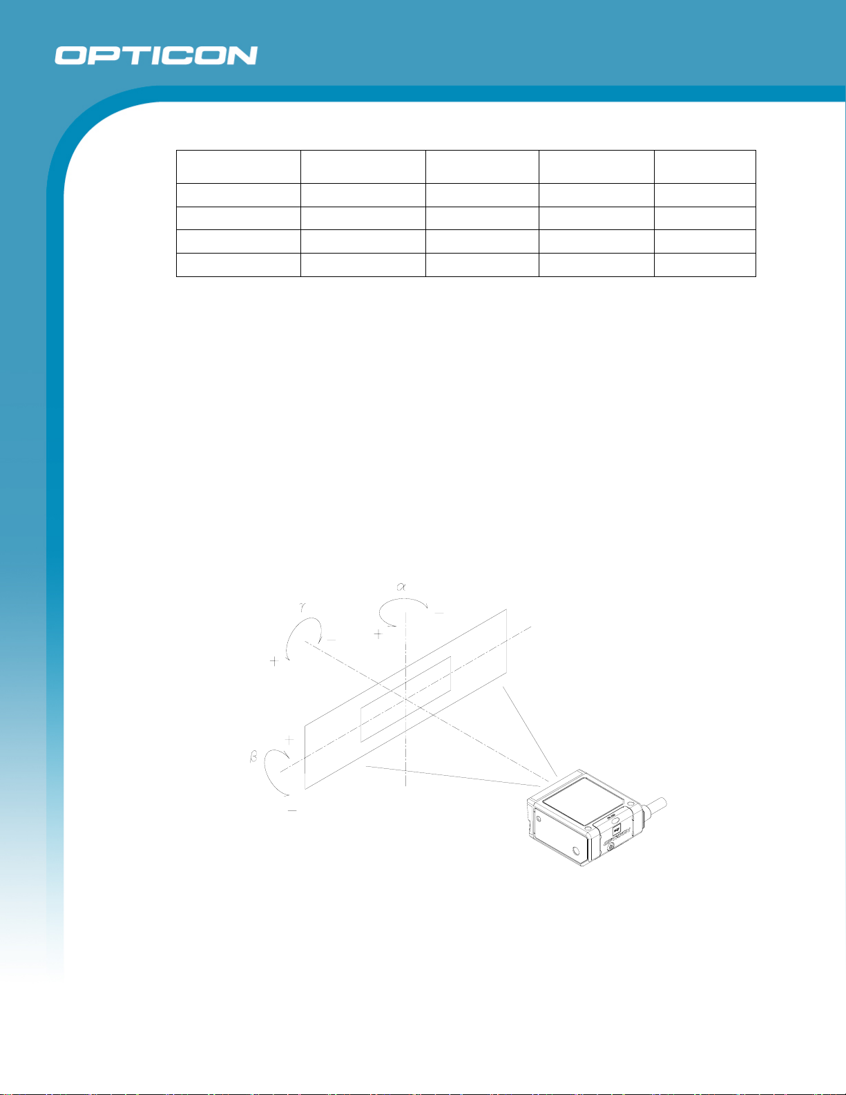
Note: α, β and γ respectively represent pitch, skew and tilt. Please see section 6.1 for
how these values are defined.
8
Page 9
5. Electrical Specifications
5.1. Electrical Characteristics
Parameter Symbol Min Typ Max Unit Notes
Opticon
NLB/RLB 1000
Specifications Manual
Power supply
voltage
Operating
current
Rush current
peak
Stand-by current I
Startup time TD — 1.5 s Scans at a rate of 800 scans/s to 1200
VDD 4.5 5.0 5.5 V
IOP — 205 500 mA LED off
I
— 2000 mA
PEAK
— 145 mA Laser off and polygon mirror on
PRE
Conditions
• Connect 1Ω resistance to a power supply line in series and measure the current
by the voltage between both ends of resistance.
• Power supply voltage is measured at a connector terminal area.
Note: If the current value does not stabilize within 1.5 seconds after activating the
polygon mirror, this scanner detects the system error, stops the polygon mirror,
and blinks green and red LEDs.
5.2. Operating Indicators
scans/s carried out within 1.5 seconds after
the polygon mirror gets activated. (See note.)
5.2.1. LEDs
There are red and green LEDs on the NLB 1000 and the RLB 1000.
1. A green LED lights up for a specific period of time after successful scanning.
You can configure the settings when the green LED is blinking.
2. A red LED lights up when any unsupported menu barcode is read in the menu
mode (200 ms).
3. Both green and red LEDs light up at the same time when either of the
following occurs:
• No scanning operation at the scan rate of 800–1200 scans/s is carried out
• No scanning operation at the scan rate of 800–1200 scans/s is carried out
within 1.5 seconds after the polygon mirror is activated.
while the polygon mirror is operating.
9
Page 10
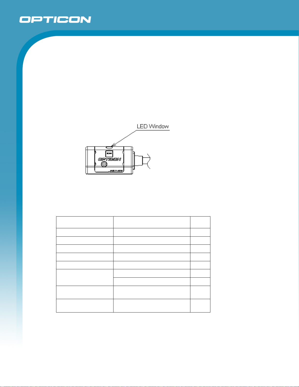
5.2.2. Buzzer
The NLB 1000 and the RLB 1000 scanners have a buzzer function; the buzzer
loudness is below 65 dB. The buzzer sounds:
1. After successful scanning at power activation.
2. After successful scanning.
3. After reading a valid menu barcode or when the scanner reads an
unsupported barcode.
4. When there is a motor malfunction.
However, it is possible to disable the buzzer by reading specific menu barcodes.
Opticon
NLB/RLB 1000
Specifications Manual
Figure 1: LED window
6. Optical Specifications
6.1. Imager Scanning
Parameter Specification Unit
Light-emitting element Red laser diode —
Emission wavelength 650 ±10 (at 25° C) nm
Light output 1.0 or less mW
Scanning method Octahedron polygon mirror —
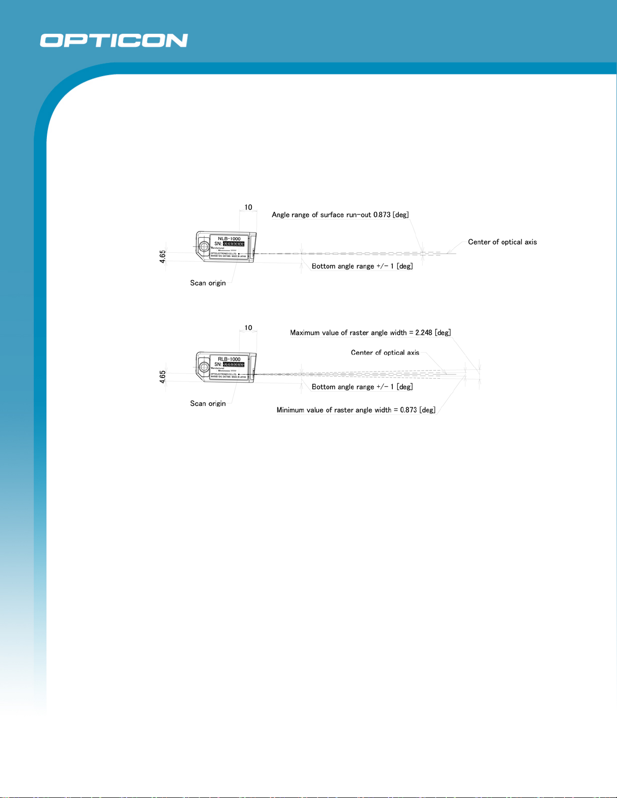
Scanning speed 1000 ±60 (at 25° C) scans/s
Vertical scan width of NLB
1000 (single scan)
Vertical scan width of RLB
1000 (raster scan)
(500 mm from front edge of scanner)
(500 mm from front edge of scanner)
Scan angle: 70 ° Scan angle
Effective scan angle: 40 °
8 or less
8 to 20
mm
mm
10
Page 11

Specifications Manual
6.2. Scanning Barcodes on Moving Items
Scanning barcodes on moving objects requires that the speed of the barcode be adjusted
to optimize the scanner’s reading performance.
The NLB 1000 and the RLB 1000 are capable of scanning low-print-quality barcodes.
Scanning barcodes on moving items may fail due to the scan rate.
Refer to the Default settings chapter for more details.
7. Technical Specifications
The conditions for technical specifications are as follows, unless otherwise specified in each
section.
Conditions
Ambient temperature and humidity 25° C or lower
85% RH or lower
Ambient light 500 to 1000 lx
Background Barcode = black
Space = white
Margin = white
Background of label = black
Power supply voltage 5.0 V
Decoding test Approve the performance when decoding is
successful in 70% of the tests.
Scan origin From the front edge of the scanner
Opticon
NLB/RLB 1000
7.1. Print Contrast Signal (PCS)
0.45 or higher (over 70% of reflectivity of space and quiet zone).
Reflectance of white bar-Reflectance of black bar
PCS=
Reflectance of white bar
Scanning performance may decline if dirt or scratches mar the optical window. Keep the
optical window clean.
7.2. Minimum Resolution
0.15 mm
11
Page 12
7.3. Scan Area and Resolution
7.3.1. Scan Area
The scannable area depends on the barcode type (PCS, resolution, length, etc.)
and the direction of the barcode surface. However, the barcode should be set
within the following area.
Opticon
NLB/RLB 1000
Specifications Manual
Figure 2: Scan area
12
Page 13
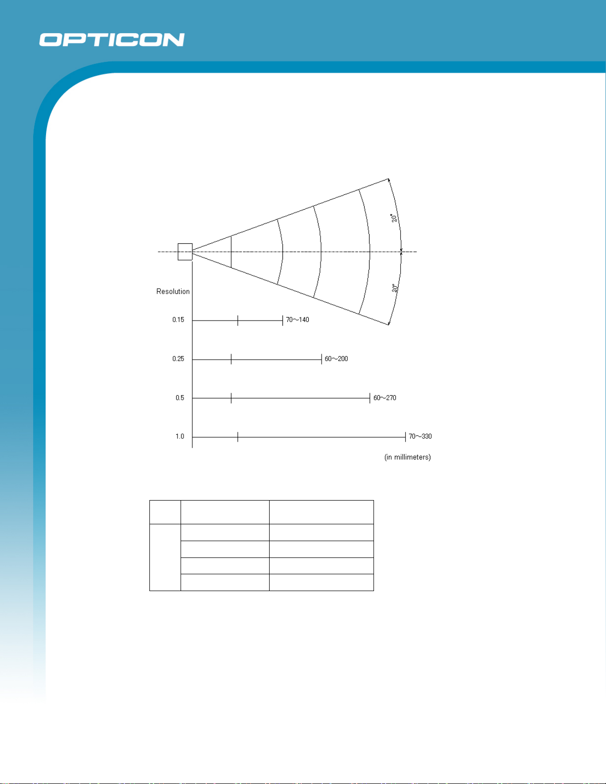
7.3.2. Depth of Field
The depth of field is measured from the front edge of the scanner. The scanning
area is rectilinear near the exit window and expands in an arc centered on a
virtual reference point in the distance.
Opticon
NLB/RLB 1000
Specifications Manual
Figure 3: Scan range
PCS Resolution (mm) Decode Depth (mm)
0.9
1.0 70–330
0.5 60–270
0.25 60–200
0.15 70–140
Conditions
Barcode Sample: OPTOELECTRONICS Test Sample
N/W Ratio: 1:2.5
Angle: α = 0°, β = 15°, γ = 0°
Curvature: R = ∞
13
Page 14
Resolution Symbology PCS Quiet Zone Digit
1.0 mm Code 39 0.9 25 mm 1
0.5 mm Code 39 0.9 18 mm 3
0.25 mm Code 39 0.9 10 mm 8
0.15 mm Code 39 0.9 7 mm 10
7.4. Pitch, Skew, and Tilt
7.4.1. Pitch Angle
α ≤ ±30°
Opticon
NLB/RLB 1000
Specifications Manual
7.4.2.
7.4.3.
Skew Angle and Dead Zone
Skew angle: β ≤ ±60° (Excluding dead zone)
Dead zone: β ≤ -7° to +9° (NLB 1000)
-8° to +10° (RLB 1000)
(There are some areas in which decoding may fail, due to specular reflection.)
Tilt Angle
γ ≤ ±25°
Figure 4: Pitch, skew, and tilt angles
14
Page 15

Conditions
Barcode Sample: OPTOELECTRONICS Test Sample
Distance: 110 mm from the front edge of the scanner
Label:
Angle: Curvature: R = ∞, Skew Angle = β +15° (for measuring Pitch Angle and Tilt Angle)
Pitch, Skew Angle, Dead Zone
PCS = 0.9, Resolution = 0.25 mm, Symbology = 9-digit Code 39,
Quiet Zone = 10 mm, N/W Ratio = 1:2.5
Tilt Angle
PCS = 0.9, Resolution = 0.26 mm, Symbology = 13-digit JAN, Quiet zone = 10 mm
7.5. Curvature
With 8-digit JAN/UPC/EAN barcodes, decoding performance is guaranteed when
R=15 mm.
With 13-digit JAN/UPC/EAN barcodes, decoding performance is guaranteed when
R=20 mm.
Opticon
NLB/RLB 1000
Specifications Manual
Figure 5: Curvature
Conditions
Barcode Sample: OPTOELECTRONICS Test Sample
PCS = 0.9, Resolution = 0.26 mm, Quiet zone = 10 mm
Distance: 110 mm from the edge of the scanner
Angle: Skew angle β = +15°
15
Page 16

8. Interface Specifications
8.1. RS-232C Interface Spec
There are three different cable specifications for models using an RS-232C interface:
1. Cable with a D-sub 9-pin connector
2. Cable with a D-sub 25-pin connector
3. Cable without a connector
Opticon
NLB/RLB 1000
Specifications Manual
8.1.1.
8.1.2.
Settings and Communication
Reading menu barcodes [ZZ] + [U2] + [ZZ] can set the RS-232C interface default.
See section 10.1 for scannable barcodes.
Parameter [U2] setting
Baud rate 9600 bps
Start/stop bits 1 bit
Data bits 8 bits
Parity bits No parity
Handshaking No handshake
Flow control time out Indefinitely
You can change the communication condition using the menu barcode.
Signal Level
Signal Name I/O RS-232C Level (V)
Bars/Off Space/On
TXD OUT -5 to -15 +5 to +15
RXD IN -3 to -15 +3 to +15
RTS OUT -5 to -15 +5 to +15
CTS IN -3 to -15 +3 to +15
16
Page 17

8.1.3. Pin Assignment and Interface Circuit
a) DB9 Pin Assignment
Pin Wire Color Signal Name Remarks
1 Brown TRIGGER Shield
2 Green TxD
3 White RxD
4 — Connected to pin 6 with jumper cable
5 Purple S.GND
6 — Connected to pin 4 with jumper cable
7 Blue CTS
8 Gray RTS
9 Open (not connected)
S Red VCC PTF
Shield F.GND
Opticon
NLB/RLB 1000
Specifications Manual
Connector: D-sub 9-pin female (with inch-long screw)
Power supply: Stereo jack
Figure 6: D-sub 9-pin connector - interface circuit
17
Page 18

b) DB25 Pin Assignment
Opticon
NLB/RLB 1000
Specifications Manual
Pin Wire
Signal Remarks
Color
Shield / 1 F.GND
2 White RxD
3 Green TxD
4 Blue CTS
5 Gray RTS
7 Black S.GND
11 Brown TRIGGER H-level: Open; L-level: Trigger
12 Yellow OK NPN open connector (DC 24 V, 30 mA)
13 Orange NG NPN open connector (DC 24 V, 30 mA)
S Red VCC PTF
Connector: D-sub 25-pin female (with inch-long screw)
Power supply: Stereo jack
Note: You can change the sequencer (OK or NG) settings using the menu
barcode. However, for a certain period of time, it will remain at OK when
H-level signals are sent and NG when L-level signals are sent.
Figure 7: D-sub 25-pin connector - interface circuit
18
Page 19

c) No connector
Wire Color Signal Remarks
Green TxD
White RxD
Gray RTS
Blue CTS
Red VCC 5 V input
Black S.GND GND
Brown Trigger H-level: Open; L-level: Trigger
Yellow OK NPN open connector (DC 24 V, 30 mA)
Orange NG NPN open connector (DC 24 V, 30 mA)
Shield F.GND shrinkable tube
Opticon
NLB/RLB 1000
Specifications Manual
Note: You can change the sequencer (OK or NG) settings using the menu
barcode. However, for a certain period of time, it will remain at OK when
H-level signals are sent and NG when L-level signals are sent.
Figure 8: No connector - interface circuit
19
Page 20

8.1.4. Character Format
8.1.5. Communication Format
Figure 10: Communication format
Opticon
NLB/RLB 1000
Specifications Manual
Figure 9:Character format
8.1.6. Handshaking
Select handshaking options using the menu or command listed below.
Handshaking Menu/Command
No handshake P0
BUSY/READY P1
MODEM P2
ACK/NAK P3
ACK/NAK NO RESPONSE P4
a) No Handshaking
The scanner attempts the communication regardless of the state of the host
computer.
Figure 11: No handshaking
20
Page 21

Opticon
NLB/RLB 1000
Specifications Manual
b) BUSY/READY
The scanner and the host computer notify each other of their state and
whether they can receive data with BUSY/READY through an RTS line. They
can communicate state to each other through a CTS line when connected as
in the following figure.
Figure 12: Busy/Ready communication
The scanner stays ON (is able to receive data) except during certain parts of
the process, such as receiving data (buzzer command execution), transmitting
data, and menu processing. The scanner checks the CTS line before
transmitting data. When it is ON, the scanner transmits data. When it is OFF,
the scanner waits for it to turn ON within a set time. The scanner will abort
transmission with an error indication (buzzer) when the CTS line is not ON
within a specified period. The Flow Control time-outs are as follows, and the
default setting is “indefinitely“ (I0).
Flow Control Time Out Menu/Command
Indefinitely I0
100 ms I1
200 ms I2
400 ms I3
Figure 13: Cannot receive command
21
Page 22

NLB/RLB 1000
Specifications Manual
CTS, TXD signal timing
When the CTS line (RTS signal of the host) is turned OFF while sending a TXD
signal, the scanner transmits one character and waits. When the CTS signal is turned
ON while transmitting a character, the character will be transmitted.
Figure 14: Signal timing
Note: When using loopback (wire connection) for RTS, CTS line of the scanner in this
setting, No handshake is not enabled.
c) MODEM
The scanner turns RTS line ON before transmitting data. Other processes are
the same as BUSY/READY.
Opticon
Figure 15: Modem transmit data
22
Page 23

Opticon
NLB/RLB 1000
Specifications Manual
d) ACK/NAK
After data has been transmitted, the scanner expects to receive one of the
following responses from the host:
• ACK response—Action: The scanner completes transmission with the
good-read buzzer and returns to the initial state.
• NAK response—Action: The scanner sends the data again and waits
for the response from the host.
• DC1 response—Action: The scanner returns to waiting for the trigger,
if it has a trigger (the initial state).
• None response—Action: The scanner sounds the error buzzer and
returns to the initial state.
ACK/NAK timeout can be set as follows using the menu or commands.
ACK/NAK Timeout Menu/Command
Indefinitely (default) XI4
100 ms XI5
500 ms XI6
1000 ms XI7
Figure 16: ACK/NAK
23
Page 24

Opticon
NLB/RLB 1000
Specifications Manual
e) ACK/NAK NO RESPONSE
When no response from the host is received within the setting time, the
scanner assumes an ACK response, and returns to the initial state without the
error buzzer. The other actions are the same as ACK/NAK.
Figure 17: ACK/NAK—No response
24
Page 25

8.2. USB Interface Specifications
8.2.1. Settings and Communication
Reading menu barcodes [ZZ] + [C01] + [ZZ] can set the USB-VCP interface
default. See section 10.1 for scannable barcodes.
Opticon
NLB/RLB 1000
Specifications Manual
8.2.2.
Connector and Interface Circuit
a) USB "A" connector
Figure 18: USB "A" connector
Pin Signal
1 VCC
2 -DATA
3 +DATA
4 GND
25
Page 26

b) Interface Circuit
Opticon
NLB/RLB 1000
Specifications Manual
Figure 19: Interface circuit
26
Page 27

9. Cable and Connector
The shape of the connector may change without prior notice.
9.1. RS-232C Cable (D-sub, 9-pin female)
(Standard specification)
Opticon
NLB/RLB 1000
Specifications Manual
Type:
Diameter:
Length:
φ3 mm (AC adapter cable)
1500 ±50 mm (main cable, excluding connector)
100 ±10 mm (AC adapter cable, excluding jack)
Straight
φ3.8 mm (main cable)
Figure 20: RS-232C cable: D-sub, 9-pin female
27
Page 28

9.2. RS-232C Cable (D-sub, 25-pin female)
(Standard specification)
Opticon
NLB/RLB 1000
Specifications Manual
Type:
Diameter:
Length:
Figure 21: RS-232C cable: D-sub, 25-pin female
Straight
φ3.8 mm (main cable)
φ3 mm (AC adapter cable)
1500 ±50 mm (main cable, excluding connector)
100 ±10 mm (AC adapter cable, excluding jack)
28
Page 29

9.3. RS-232C Cable (no connector)
(Standard specification)
Opticon
NLB/RLB 1000
Specifications Manual
Type:
Diameter:
Length:
φ3 mm (AC adapter cable)
1500 ±50 mm (main cable)
Straight
φ3.8 mm (main cable)
Figure 22: RS-232C cable: no connector
9.3.1. Pin Assignment
a) DB9 Pin Assignment
Pin Wire Color Signal Remarks
1 Brown TRIGGER
2 Green TxD
3 White RxD
4 Jumper
5 Purple S.GND
6 Jumper
7 Blue CTS
8 Gray RTS
9 N.C.
S Red VCC PTF
Shield F.GND
29
Page 30

b) DB25 Pin Assignment
Pin Wire Color Signal Remarks
Shield / 1 F.GND
2 White RxD
3 Green TxD
4 Blue CTS
5 Gray RTS
11 Brown TRIGGER
12 Yellow OK
7 Black S.GND
13 Orange NG
S Red VCC PTF
c) No Connector Pin Assignment
Opticon
NLB/RLB 1000
Specifications Manual
Wire Color Signal Remarks
Green TxD
White RxD
Gray RTS
Blue CTS
Red VCC
Yellow OK
Orange NG
Black S.GND
Brown TRIGGER
Unshielded F.GND
30
Page 31

9.4. USB Cable
(Standard specification)
Opticon
NLB/RLB 1000
Specifications Manual
Type:
Diameter:
Length:
1450 ±50 mm (main cable, excluding connector)
Straight with clamp filter
φ3.8 mm (main cable)
Figure 23: USB cable
9.4.1. Pin Assignment
Pin Signal
1 VCC
2 -DATA
3 +DATA
4 GND
10. Default Settings
10.1. Barcodes
Scan the following menu barcodes to return to the default settings.
RS-232C Default
Functions Menu labels Menu codes
SET
RS-232C
END
_ZZ_
_U2_
_ZZ_
ZZ
U2
ZZ
31
Page 32

USB-VCP Default
Functions Menu labels Menu codes
Opticon
NLB/RLB 1000
Specifications Manual
SET
USB-VCP
END
_ZZ_
_C0_
_ZZ_
10.2. Default Settings 1: Readable Codes
Symbology Read Transmit
Code
Length
UPC-A
UPC-A Add-on X X
UPC-E
UPC-E Add-on X X
EAN-13
EAN-13 Add-on X X
EAN-8
X
X
X
X
Transmit
CD
Calculate
ZZ
C01
ZZ
CD
Set
Prefix
—
—
—
—
—
—
—
Set
Other
Suffix
CR
CR
CR
CR
CR
CR
CR
EAN-8 Add-on X X
Chinese Post X X
Codabar / NW-7
Code 11 X X X
Code 39
Code 93
GS1-128
EAN-128 X X
IATA
Industrial2of5
Interleaved2of5
X
X
X X
X X
X
X
X
32
X
X
X
X
X
X
—
—
—
—
—
—
—
—
—
—
—
CR
CR
CR Not transmit ST/SP
CR
CR Not transmit ST/SP
CR
CR
CR
CR
CR
CR
Page 33

Opticon
NLB/RLB 1000
Specifications Manual
Symbology Read Transmit
Transmit
Code
Length
Matrix2of5 X X
MSI/Plessey
S-Code
Telepen
Trioptic
UK/Plessey
X CD1 CD1
X
X X
X
X
Notes:
• In the “Reading” column, “
reading.”
• In the “Transmit code length” column, “
means “Do not transmit code length.”
• In the “Transmit CD” column, “
not transmit check digit.”
Calculate
CD
” means “Enable reading” and “X” means “Disable
CD
X
X
X
” means “Transmit code length” and “X”
” means “Transmit check digit” and “X” means “Do
Set
Prefix
—
—
—
—
—
—
Set
Other
Suffix
CR
CR
CR
CR
CR Not transmit ST/SP
CR
• In the “Calculate CD” column, “
” means “Calculate check digit” and “X” means
“Do not calculate check digit.”
• “— “ means “not supported.”
• In the “Prefix” column, “—“ means “there is no prefix setting.”
• EAN-128 barcodes are processed as Code-128 and “FNC1” data will be ignored.
33
Page 34

10.3. Default Settings 2: Read Options, Trigger, Buzzer
Item Default Setting
Setting the number of characters Fixed length OFF all codes
Read mode Single read
Multiple read reset time 500 ms
Add-on wait mode 500 ms
Redundancy
Inter-character gap check Character 1 >
Multiple column read Disable
Limitation of decode time (see note) Disable
Read time 2 seconds
Buzzer duration 50 ms
Buzzer tone 2.6 kHz
Buzzer loudness Loud (maximum)
Indicator duration (Green LED) 200 ms
Code 39 minimum digit 1 digit
NW-7 minimum digit 5 digits
Industrial 2of5 minimum digit 5 digits
Interleaved 2of5 minimum digit 6 digits
MSI/Plessey minimum digit
(only when enabled)
Default option
([X0] setting)
Other options
([X1 .. X3] setting)
([BS .. BW] setting)
Read 1 times, redundancy = 0
Read n times, redundancy = n+1 for following symbologies
and lengths:
● Code 39 with length <= 5
● MSI/Plessey with length <= 4
● IATA, Industrial 2of5, Interleaved 2of5 with length <= 8
● Matrix 2of5 (& Chinese Post), S-code with length <= 8
● Codabar (NW7) with all lengths
● Code 11 with length <= 5
3 digits
Opticon
NLB/RLB 1000
Specifications Manual
Note: Refer to 6.2 Scanning Barcodes on Moving Items
34
Page 35

Specifications Manual
10.4. Default Settings 3: Communication Settings
Item Default Setting
Baud rate 9600 bps
Start/stop bits 1 bit
Data bits 8 bits
Parity bits No parity
Handshaking No handshake
Flow Control Time Out Indefinitely
The communication condition can be changed by using the menu barcode.
10.5. Default Settings 4: Scanning Barcodes on Moving Items
Scanning performance when scanning barcodes on moving items may be improved by
configuring the settings below.
Opticon
NLB/RLB 1000
Functions Menu labels Menu codes
SET
Limitation of Decode Time: Enable
END
The degree of improvement of scanning performance using this configuration differs
depending on the scan rate and the redundancy configurations.
Return the scanner to its default settings by configuring the settings below.
Functions Menu labels Menu codes
SET
Limitation of Decode Time: Disable
END
_ZZ_
_E7K_
_ZZ_
_ZZ_
_E7J_
_ZZ_
ZZ
E7K
ZZ
ZZ
E7J
ZZ
35
Page 36

11. Serial Number and Labeling
11.1. Serial Label
The serial number shown below is affixed to the scanner. Letters are printed on a matteblack background and serial numbers in black on a white background.
Opticon
NLB/RLB 1000
Specifications Manual
Figure 24: Serial number label
11.2. Laser Caution Label
The laser caution label is affixed on the upper side of the scanner. Letters are printed in
black on a yellow background.
Label Position Laser Caution Label / CDRH Label
Figure 25: Laser caution label
36
Page 37

11.3. Certification Logo Label
The certification logo label is attached on one side of the cable.
Figure 26: Certification logo label
Opticon
NLB/RLB 1000
Specifications Manual
11.4. Back Side Label
The back side label is attached on the other side of the cable.
Figure 27: Backside label
37
Page 38

12. Packaging Specifications
12.1. Individual Packaging Specification
Put the scanner in a protective foam bag and place it in an individual packing box.
Size of the package (after assembly): 245 (W) x 110 (D) x 40 (H) mm
Opticon
NLB/RLB 1000
Specifications Manual
Figure 28: Packaging
38
Page 39

12.2. Collective Packaging Specification
Put 50 individually packaged scanners in a collective packing box.
Size of the package (after assembly): 600 (W) x 520 (D) x 250 (H) mm
Opticon
NLB/RLB 1000
Specifications Manual
Figure 29: Collective packaging
Note: The “RO” mark labeled on the package tray or package box guarantees that the
applicable product has passed our test of RoHS restrictions compliance (the restriction of
the use of certain hazardous substances in electrical and electronic equipment, 2002/95
EC). However, this document does not have any legal weight in the European Union.
39
Page 40

13. Durability
13.1. Electrical Noise
No malfunction occurred when sinusoidal electrical noise (50Hz–100kHz, < 0.1Vpp) was
added to a power supply line.
Conditions
Barcode Sample: OPTOELECTRONICS Test Sample
PCS: 0.9
Resolution: 0.25 mm
Symbology: 9-digit Code 39
Quiet zone: 10 mm
N/W ratio: 1:2.5
Distance: 150 mm
Angle: α = 0° β = 15° γ = 0°
Curvature: R = ∞
Power supply voltage: 5.0 V
Opticon
NLB/RLB 1000
Specifications Manual
13.2. Static Electricity
Air discharge: ±8 kV MAX (No malfunction)
±15 kV MAX (No destruction)
Contact discharge: ±4 kV MAX (No malfunction)
±8 kV MAX (No destruction)
Measurement environment: Use electrostatic testing device compliant with IEC 61000-4-2
Discharge resistance: 330 Ω
Capacitor charging: 150 pF
13.3. Shock
13.3.1. Drop Test (without packaging)
No malfunction occurred after the following drop test.
Drop test: Drop the scanner from a height of 30 cm onto a plastic tile resting on a
table (once on each of 6 sides).
13.3.2.
Drop Test (with individual packaging)
No malfunction occurred after the following drop test.
Drop test: Drop an individually packaged scanner from a height of 60 cm onto a
plastic tile resting on a table (once on each of 6 sides).
40
Page 41

13.4. Vibration Strength
13.4.1. Vibration Test (without packaging)
No malfunction occurred after the following vibration test.
Vibration test: Increase the frequency of the vibration from 10 Hz to 100 Hz with
accelerated velocity 19.6m/s
this routine in each X, Y, Z direction once for 60 minutes each.
Opticon
NLB/RLB 1000
Specifications Manual
2
(2G) for 30 minutes in non-operating state. Repeat
13.4.2.
Vibration Test (with individual packaging)
No malfunction occurred after the following vibration test.
Vibration test: Put the scanner in an individual packing box. Increase the
frequency of the vibration from 10 Hz to 100 Hz with accelerated velocity 19.6m/s
(2G) for 30 minutes in non-operating state. Repeat this routine in each X, Y, Z
direction once for 60 minutes each.
13.5. Water Resistant and Dust and Drip Proof
IEC IP54
IEC60529
JIS C0920
13.6. Cable Strength
13.6.1. Cable Stretch Test
No cable malfunction occurred after the following stretch tests.
Stretch Test: Fix the scanner and pull the cable with the force of 2.5 kg (24.5N) for
1 second. Repeat 20 times.
13.6.2.
Cable Tail Bending Test
No cable malfunction occurred after the following bending tests.
Bending Test: Fix the scanner and attach a weight of 500 grams (4.9N) and swing
the cable back and forth at an angle of 60 degrees. Repeat 1,000 times.
2
Figure 30: Cable tail bending test
41
Page 42

Specifications Manual
14. Reliability
MTBF (Mean Time Between Failures) of the NLB 1000 and the RLB 1000 is 30,000 hours,
excluding the laser diode and the scan unit.
Life cycle of the laser diode is 10,000 hours and that of the mirror motor scan unit is 20,000
hours.
The estimate of MTBF and product life cycle is based on standard operation of the product
within the recommended temperature range and without extreme electronic or mechanical
shock.
15. Trigger and Read Options
15.1. Trigger Switch
The trigger switch for the NLB 1000 and the RLB 1000 is on the back side of the scanner.
The switch is labeled SCAN, as shown in the figure below. Unless the scanner read
options are configured otherwise, you can start the scanning operation by pressing this
switch. (By default, manual scanning is enabled.)
Opticon
NLB/RLB 1000
Figure 31: Trigger switch
15.2. Trigger Modes
Disabled: When this option is selected, the reader will stay on all the time.
Enabled: After receiving a trigger signal, the barcode reader will turn on and the read
cycle starts. The reader will stay on for a time as set in 'Read time options'. The trigger
signal can be initiated in the following ways:
Manual mode: When the trigger key is pressed, the read cycle starts.
Serial mode: The read cycle starts at the time set in 'Read time options' after a serial
command (<ESC>Z<CR>) is received.
Hardware mode: After an electrical pulse (low), the read cycle starts at the time set in
'Read time options' and behaves as if the trigger is continuously released.
15.3. Read Modes
Single read mode: When a symbol has been decoded, the reader will be turned off. The
reader must be triggered again to read another symbol. This option and 'Disable trigger'
cannot be programmed at the same time.
42
Page 43

Multiple read mode: When a symbol has been decoded, the reader will stay on for a time
(set by 'Read time options') or indefinitely, if the trigger switch has been disabled. The
same symbol can only be decoded again after the symbol has not been detected for a set
number of scans (multiple read reset time).
Continuous read mode: The reader will produce as much data as it can decode even if it
is reading the same symbol. This mode is mainly used for demonstration and diagnosis.
16. Regulatory Compliance
16.1. Laser Safety
The scanner emits laser beams.
• JIS C6802:2005 Class 2
• IEC60825-1+A2:2001 Class 2
• FDA CDRH Laser Class II. Complies with 21 CFR 1040.10 and 1040.11 except
for deviations pursuant to laser notice No. 50 dated June 24, 2007.
Opticon
NLB/RLB 1000
Specifications Manual
Class II laser devices are not considered to be hazardous when used for their intended
purpose. Avoid staring into the laser beam.
16.2. EMC
EN55022
EN55024
VCCI Class B: This is a Class B product, to be used in a domestic environment based on
the Technical Requirement of the Voluntary Control Council for Interference from
Information Technology Equipment (VCCI). If this is used near a radio or television
receiver in a domestic environment, it may cause radio interference. Please install and
use the equipment according to the instruction manual.
FCC Part 15 Subpart B Class B: This device complies with part 15 of the FCC Rules.
Operation is subject to the following two conditions: (1) this device may not cause harmful
interference, and (2) this device must accept any interference received, including
interference that may cause undesired operation.
16.3. RoHS
RoHS: The restriction of the use of certain hazardous substances in electrical and
electronic equipment, 2002/95 EC.
43
Page 44

17. Safety
Handle this product carefully. Do not deliberately subject it to any of the following.
17.1. Shock
Do not throw or drop the scanner.
Do not place heavy objects on the cables.
17.2. Temperature Conditions
Do not use the scanner at temperatures outside the specified range.
Do not pour boiling water on the scanner.
Do not throw the scanner into the fire.
Do not forcibly bend the cables at low temperatures.
17.3. Foreign Materials
Do not immerse the scanner in liquids.
Opticon
NLB/RLB 1000
Specifications Manual
Do not subject the scanner to chemicals.
17.4. Other
Do not plug/unplug the connectors before disconnecting the power.
Do not disassemble this product.
Do not place the product near a radio or a TV receiver, as the scanner may cause
reception problems.
The scanner may be damaged by voltage drops.
The scanner may not perform properly in environments when placed near a flickering
light, such as a computer monitor, television, etc.
Opticon shall not be held responsible for any damages caused by using an AC adapter
not provided by Opticon.
44
Page 45

18. Mechanical Drawing
Opticon
NLB/RLB 1000
Specifications Manual
Figure 32: Mechanical drawing
45
 Loading...