

Page 1

User’s & Set Up Manual
Controller RFS6000
RF-DC communication station
Page 2

U
SER’S
& S
ET UP MANUAL
RFS 6000
CAUTION:This user’s manual may be revised
or withdrawn at any time without prior notice.
Copyright 2000
Opticon Sensors Europe B.V.
All rights reserved.
This manual may not, in whole or in part, be
copied, photocopied, reproduced, translated
or converted to any electronic or machine
readable form without prior written consent of
Opticon Sensors Europe B.V.
Limited warranty and disclaimers
By opening the package of this product you agree to
become bound by the liability and warranty conditions
as described below.
Under all circumstances this manual should be read
attentively, before installing and or using the product.
In no event, Opticon Sensors Europe will be liable for
any direct, indirect, consequential or incidental
damages arising out of use or inability to use both
the hardware and software, even if Opticon has been
informed about the possibility of such damages.
A serial number appears on all Opticon products.
This official registration number is strictly related to
the device purchased. Make sure that the serial
number appearing on your Opticon device has not
been removed.Servicing by our Repair Department
can only be carried out under warranty.
All Opticon products are warranted for a period of one
year after purchase, covering defects in material and
workmanship. Opticon will repair or, at its opinion,
replace products that prove to be defective in material
or workmanship under proper use during the warranty
period.
Opticon will not be liable in case modifications are
made by the customer.In such case the standard
repair charge will be applicable.The standard charge
for repair will also be applicable in case no defect is
found at all.These rules also apply for products that
are still under warranty. Therefore, you are advised
to have the product’s specifications allways at hand.
Trademarks used are property of their respective owners.
The general use and functioning of the
controller will be described in this manual.
The exact behavior of the controller
depends on the user application that is
running. For instructions about applications
please consult the documentation of
that software.
Please read this manual carefully
before using the controller, to maximise
the efficiency of this controller.
RFS6000-ver2 / printed 11 01
Page 3

CONTENTS
page
INTRODUCTION 3
1. THE CONTROLLER RFS6000 4
1.1 Unpacking 4
1.2 Antenna assembly 4
1.3 Position 4
1.4 Detailed view 4
1.5 Handling precautions 5
2. INSTALLATION AND STARTUP 6
2.1 Power supply 6
2.2 Connect to computer 6
U
SER’S
& S
ET UP MANUAL
RFS 6000
INTRODUCTION
The RFS6000 is a RF network controller for
radio frequency communication with data
collectors of Opticon (hereafter called RF
device).
3. OPERATION OF THE
CONTROLLER 7
4. INSTALL SOFTWARE 8
5. TECHNICAL SPECIFICATIONS 10
5.1 Electrical specifications 10
5.2 Transceiver specifications 10
5.3 Functionality 10
5.4 Environmental specifications 10
5.5 Physical specifications 10
6. TROUBLESHOOTING 11
7. PRODUCT ORDERING
INFORMATION 11
APPENDIX 12
A. PINOUT DESCRIPTION 12
B. DESCRIPTION FIRMWARE 13
The controller is equipped with a built in radio
transceiver for short range communication.It
communicates with compatible portable
Opticon devices.
The controller normally is provided with
firmware.To allow updates of the firmware the
controller is equipped with flash-ROM, where
data can be erased and data of new installed
software can be stored.
Data transmission to a host system can be
achieved by the RS232 interface. The
controller is prepared for use in a RS485
network structure.
3
Page 4
U
!
!
SER’S
& S
ET UP MANUAL
RFS 6000
1.2 ANTENNA ASSEMBLY
Before operation first screw the antenna into
the applicable hole of the controller by hand.
THE
3
1
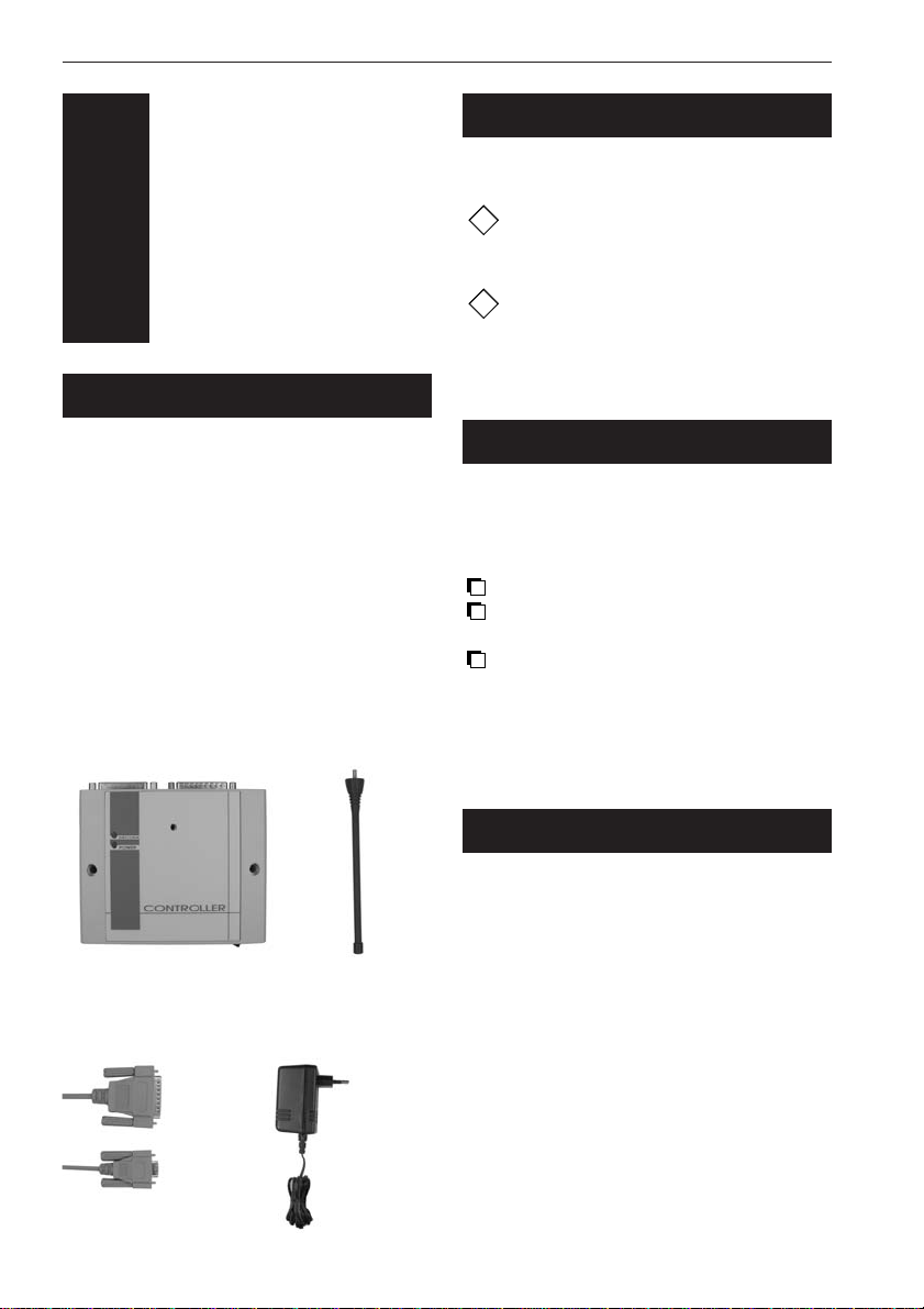
1.1 UNPACKING
Before you begin your installation, be certain
that you have all the items listed below:
Remove the packaging and check for any
physical damage.We recommend you to save
all packaging: it should be used whenever you
need to transport your terminal for service.
Damage caused by improper repackaging is
not covered by the warranty.
RFS6000
package contents:
The RFS 6000 controller Antenna
CONTROLLER
RFS6000
Use only the antenna as supplied by
Opticon. Antenna’s with other
specifications are not allowed.
Fix the antenna handtight. Screwing
the antenna too tight may cause serious
damage to the antenna.
1.3 POSITION
The controller operates with the maximum
result if it can operate in free space. Place
the controller under the following conditions:
Check if the antenna is properly fixed.
Place the controller at a central point,
preferably as high as possible.
Avoid objects (for example metal objects)
in the near area that may reflect or
obstruct the radiation of the
electromagnetic field.
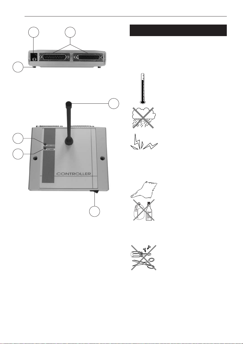
1.4 DETAILED VIEW
ADDITIONALS FOR RFS6000:
Serial cable RS232 Power supply
1. Antenna
short range antenna for radio frequency
communication
2. Power switch
3. Power LED (red)
ON: Power is ON
blinking at start: ready for download
continous blinking: no software detected
OFF: Power is OFF
4. Decode LED (green)
blinking: data received from Opticon device
OFF: no data
4
Page 5
6 7
1
2
3
4
5
*
*
U
SER’S
& S
ET UP MANUAL
RFS 6000
1.5 HANDLING PRECAUTIONS
To avoid malfunctioning and to ensure years
of trouble free operation, pay attention to the
following:
General use
Do not use or leave the product
in extremely hot areas - like
direct sunlight, near a heater,
or in a car - or in areas that are
very cold, humid, moistured or
dusty.
Do not expose the product to
rain or water splash
Do not leave the terminal in an
area where static charge is
accumulated, or near devices
where electromagnetic emission
is generated.
General cleaning instructions
5. Cushion pads
4 pads for placement on a counter
6. DC input socket
input for 5V adaptor of Opticon
7. RS 232 / RS485 socket
one DB 25 male socket and one DB 25
female socket is provided for connection to
PC or to other RFS6000 controller
Clean the exterior by wiping it
with a soft, dry cloth. Do not
use much water.
Do not use thinner, white spirit
or other solvents.
Maintenance
There are no user-serviceable
parts inside the controller. So
do not try to take it apart.
The manufacturer will not be
liable for any damage caused
by the customer.
In case of malfunction that can not be solved
by the trouble-shooting instructions in this
manual, please consult your supplier or our
service department.
5
Page 6

RS 232
POWER
!!!
U
SER’S
3
2
& S
ET UP MANUAL
RFS 6000
INSTALLATION
AND
STARTUP
This chapter will provide instructions on how
to install the controller.
After the installation the terminal is ready for
receiving your application program.Please
refer to the documentation of the used
software.
Exercise caution at all times when
working with AC powered equipment.
Turn off your host computer before
installation.
Do not operate these devices before
reading this chapter.
Consult Appendix B for troubleshooting
information if you experience difficulties
after the installation.
Because of the special pin-out of the
connectors, use the cables supplied
by the manufacturer.
When you need another cable for a
certain device, that is not supplied,
contact your supplier to purchase the
right cable. In case another cable is
used, take notice of the pin-out
specifications further in this manual.
2.1 POWER SUPPLY
The controller is powered directly from a DC
voltage.Herefor, use the 5V adapter as
supplied.
1. Plug the rounded end of the power cord
on the back side of the controller.
2. Plug the adapter into an 220V AC outlet.
2.2 CONNECT TO COMPUTER
Installing controller in serial mode:
(see figure below)
1. Check if the power supply is connected.
2. Plug the DB25 connector of the RS232
interface cable on the back side of the
controller.
3. Plug the DB9 connector of the RS232
interface cable into the serial port of the
host computer.
Figure 2.2.1 Serial mode
6
Page 7

3
3
OPERATION
OF THE
CONTROLLER
U
SER’S
& S
ET UP MANUAL
RFS 6000
The RF network between the RFS6000 and
the RF devices of Opticon is specially
designed for data collection.In such applications
the data is transmitted in small chunks and
gathered at the host.The communication
between the RF device and the host is
achieved by short messages sent through the
RFS6000 controller.Examples of short
messages are scanned data from one RF
device (e.g.barcode) sent to the host
computer, and responses related to the data
(e.g. name, price) sent from the host computer
to the portable RF device.
Reliable communication between the RF
devices and the controller is assured by the
protocol that is implemented in the controller.
For the communication between controller and
host firmware is available.The firmware
supports 2 protocols.
Free running protocol:
This protocol is designed for using the
controller without the need of software
amendments on the PC. It suppor ts one-way
communication only, meaning that a return
message is sent by the controller to the host
only, the host can not send messages to the
RF devices.
Description of the protocol and communication
settings are stated in Appendix B.
For installation and setup of the firmware, see
chapter 4.
Two-way protocol:
This protocol is based on the ANSI X3.28
standard. Using this protocol the host can also
send return messages to the RF devices.
Opticon has a DLL available that allows easy
development with tools like delphi and C++
Builder (Borland products).
7
Page 8

U
SER’S
& S
ET UP MANUAL
RFS 6000
3
4
To allow easy updates of firmware, the
controller is equipped with a flash-ROM.This
ROM can be erased, and then the user can
install new firmware.
Install needs
To install Opticon firmware sucessfully on the
controller you need:
PC with windows95/98/2000 environment
Opticon installation software ‘appload’
version EAGV0106 or higher.
Opticon software for RFS6000 version
IBBV0102 or higher.
The program ‘appload’can be obtained from
the Opticon internet site or your local dealer.
Install notes
Firmware loading settings:
Only the COM port and software needs to be
set in ‘appload’.Other details like baudrate,
number of databits, etc. are irrelevant for
loading firmware to RFS6000.
Installation failure:
The firmware installation will not affect the
boot loader program in the RFS6000.When
the installation fails, simply switch the
RFS6000 off and back on, and repeat the
procedure.
INSTALL
SOFTWARE
Downloading and installing sequence:
Connect the RFS6000 to a PC that runs
windows95/98/2000.
Make sure the RFS6000 is switched off.
Start the program 'appload' on the PC.
Check the version.This should be
EAGV0106 or higher.
Make sure that the right COM port is
selected in 'appload'.To do this, select
menu item 'Settings' - 'Port' and select the
port whereto the controller is connected.
Select the menu item 'File' - 'Download'.
A dialog box will pop-up where you can
select the software for the RFS6000.
Wait for pressing the open button.
Switch the RFS6000 on.The unit will start
blinking the red LED.
While the red LED is still blinking return to
the dialog box on the PC and select the
'Open' button.The software will start the
downloading automatically.
Note!
When the red LED already lights continuously,
downloading is not possible anymore. To
return to download mode simply switch off
the controller and then switch back on.
Check the progress bar of ‘appload’ to
reach 100%. At that moment the software is
installed.The unit will restart automatically,
and starts running the newly installed
firmware.
8
Page 9

U
SER’S
& S
ET UP MANUAL
RFS 6000
Setup notes:
For the setup of the controller the user need
the program ‘SetupRFS’.This can be obtained
from the Opticon internet site or your local
dealer.The program is also available in
Opticon’s C-development kit for handheld
terminals.
Use this program to setup the RFS6000,
selecting free-running or X3.28 protocol, and
setting communication parameters.
You can also use SetupRFS to set the base
station address. For each RFS6000 in a group
of RF networks that are within receiving range
of one another, different base station
addresses should be set, to prevent undefined
behaviour caused by mutual interference.
The RF device must be setup using the
corresponding base station address of the
applicable station, so that it will communicate
only with the required RFS6000.To setup the
RF device, consult the manual of the software
as supplied with your RF device.
Setup sequence using ‘SetupRFS’:
Make sure no programs are running
(such as appload) that are using the COM
port to which the RFS 6000 is connected.
Start the SetupRFS program
In the "settings" menu, select the COM
port to which the RFS 6000 is connected.
Select the desired configuration.
Switch on the RFS6000, and while its
power LED is still flashing, press the
"store settings" button in the SetupRFS
window.
If an error message is shown, switch the
RFS6000 off and repeat the previous step.
9
Page 10

U
SER’S
& S
ET UP MANUAL
RFS 6000
3
5
5.1
Voltage requirement 5V ± 5 %
Current consumption Typical use 100 mA
5.2
Frequency 433.92 MHz license free band
Transceiving system RF-DC
Operation range up to 50 meters distance from
ERP max. 10 mW
(effective radiated power)
Transmission speed up to 38400 bits/s
5.3
TECHNICAL
SPECIFICA TIONS
Electrical specifications
Max. 180 mA
Transceiver specifications
aerial antenna system
antenna, depending on
environment characteristics
(practical transmission speed
depends on application)
Functionality
5.4
Environmental specifications
Temperature 0 - +55 oC in operation
Emission According to EN50081, part 1
Immunity According to EN50082, part 1
R&TTE conform I-ETS 300-220
5.5
Physical specifications
Dimensions 125 x 140 x 180 mm
(l x w x h) (incl. antenna)
Weight 260 g
Standard cable DB25 male / DB9 female
-40 - +70 oC in storage
Memory 32 KByte ROM
Microprocessor 16-bit
Firmware updates may be downloaded
Interfaces supported RS232
128 KByte FlashROM
for program storage
32 KByte RAM
via RS232 cable
RS485
10
Page 11

?
?
?
?
3
6
TROUBLE
SHOOTING
3
7
U
SER’S
& S
ET UP MANUAL
RFS 6000
PRODUCT
ORDERING
INFORMATION
This chapter contains information to solve
problems you may encounter when using the
controller.
It is possible that you may not solve the
problems, despite our descriptions. In this
case, please contact your supplier or the
technical support department of Opticon.
The controller does not respond to PC.
The red power LED is off.
Check if the power supply is properly
connected. If necessary reconnect.
The red power LED is on.
Check if the cables are properly connected.
If necessary reconnect.
Check if the baudrate in the application
corresponds with the baudrate of the PC.
The red power LED blinks continuously.
The controller does not detect software.
Software might not be downloaded or wrong
software might be downloaded.Download
the right application from the PC to the
controller.
Data from the communicating device is not
received.
Controller
RFS 6000 RF controller A6020000010
Powersuppl y
5V power supply A50500N0010
Connection cables
RS 232 cable C40120N0170
DB25 male / DB 9 female
The green decode LED is off.
Move the communicating device closer to
the antenna until you entered the field of
the antenna.
11
Page 12

U
PIN
1
2
3
4
5
7
9 / 11
10 / 12
IN/OUT
-
OUT
IN
OUT
IN
-
IN / OUT
IN / OUT
FUNCTION
FRAME GROUND
RS232 TxD
RS232 RxD
RS232 RTS
RS232 CTS
SIGNAL GROUND
RS485 Tx/Rx +
RS485 Tx/Rx -
DB 25 FEMALE
DB 25 MALE
1
1
25
25
3.5 MM
STEREOPLUG
0 V
+5 V
Not connected
SER’S
& S
ET UP MANUAL
RFS 6000
3
A
Pinout description of connectors of the
controller which can be used for connection:
APPENDIX
PINOUT
Pinout description of the 5 V power plug:
12
Page 13

U
SER’S
& S
ET UP MANUAL
APPENDIX
3
B
DESCRIPTION
FIRMWARE
Firmware V ersion IBBxxxxx.S2
(xxxxx denotes version, e.g.V0102 = version 1.02 or higher)
Communication parameters: Baudrate 115200
8 databits, 1 stopbit, no parity bit
Protocol: Language: ANSI X3.28 standard
Type: select type using SetupRFS program
Return messages: host can send return messages to RF devices
RFS 6000
Description:
With this protocol, the host must always send a response to the RFS6000 when it receives a
message from the RF device.The response may contain useful data relating to the received
message.The host is only allowed to send a message in response to a message from the RF
device.*
To be able to address a specific RF device in the network, a 3-byte header precedes the
message.The length of a message (including the header) is var ia ble, bu t n ever exceeds 256
bytes.A message looks like this:
<RF device address><Message type><Sequence number> ….data ….
For transmission and response the same protocol is used, however the roles of sender and
receiver are reversed.The 3 byte header of the response message must be identical to that of the
corresponding received message.
* Note: If the application requires special messages to be sent to the RF device that are not initiated by an action of the user,
the RF device could be programmed to regularly send empty messages to ask for these messages.
13
Page 14

U
SER’S
& S
ET UP MANUAL
Transmit a message from RF-device to host:
Sender = RFS6000
Receiver = Host
Transmit a message Host to RF-device:
Sender = Host
Receiver = RFS6000
___________________________________________________________________________
RFS 6000
-> <ENQ> Sender first sends an enquiry character to indicate that it
wants to send a message
___________________________________________________________________________
<ACK> <- Receiver responds that it is ready to receive the message
___________________________________________________________________________
-> <DLE><STX> Sender sends a 'start of transmission’ sequence.
___________________________________________________________________________
-> ...message... Sender sends the message, with the format as described above.
When a byte in the message is equal to DLE, an extra DLE is
sent, to indicate that this DLE byte is part of the data.
___________________________________________________________________________
-> <DLE><ETX> Sender sends a 'end of transmission’ sequence.
___________________________________________________________________________
-> <BCC> Sender sends a 'block check character'.This byte is the
logical X-OR over all the bytes, starting with the <DLE><STX>
sequence.
___________________________________________________________________________
<-<ACK> Receiver has to respond with ACK, if the message was
received. (the BCC is found to be correct)
<-<NAK> Receiver has to respond with NAK, if the message was not
received correctly. (the BCC is found to be incorrect)
___________________________________________________________________________
14
Page 15

U
SER’S
& S
ET UP MANUAL
RFS 6000
Protocol: Type: free running (select type using SetupRFS program)
Return messages: The string sent by the por table RF device is simply forwarded to
the host.
Any data sent by the host to the RFS6000 is discarded.
Description: not applicable
15
Page 16

U
SER’S
& S
ET UP MANUAL
RFS 6000
Opticon Article Code
O0225000050
16
 Loading...