

Page 1
Users Manual
Opticon Ethernet Converter
RS232 <-> Ethernet
Page 2

CAUTION: This users manual may be revised or withdrawn at any time without prior notice.
Copyright 2007
Opticon Sensors Europe BV
All rights reserved.
This manual may not, in whole or in part, be copied, photocopied, reproduced, translated or converted to any
electronic or machine readable form without prior written consent of Opticon Sensors Europe BV
BY OPENING THE PACKAGE OF THIS PRODUCT YOU AGREE TO BECOME BOUND BY THE LIABILITY
AND WARRANTY CONDITIONS.
IN ALL CIRCUMSTANCES THIS MANUAL SHOULD BE READ ATTENTIVELY, BEFORE INSTALLING
AND/OR USING THE PRODUCT.
Serial number
A serial number appears on all Opticon products. This official registration number is strictly related to the device
purchased. Make sure that the serial number appearing on your Opticon device has not been removed.
Removing the serial number might affect the warranty conditions and liability disadvantageously, so please be
strict at maintaining the label with serial number on the Opticon product.
Warranty / Warranty period / Liability
Unless otherwise agreed in a contract, all Opticon products are warranted for a period of two years after
purchase, covering defects in material and workmanship. Opticon will repair or, at its opinion, replace products
that prove to be defective in material or workmanship under proper use during the warranty period. Opticon will
not be liable in case the customer made modifications. In such case the standard repair charge will be
applicable. The standard charge for repair will also be applicable in cases where no defect is found at all. These
rules also apply for products that are still under warranty. Under no circumstance Opticon Sensors Europe BV
will be liable for any direct, indirect, consequential or incidental damages arising out of use or inability to use
both the hardware and software, even if Opticon has been informed about the possibility of such damages.
Packaging
The packing materials are not harmful for the environment. We recommend that you save all packing materials,
as it should be used whenever you need to transport your scanner (e.g. for service). Damage caused by
improper repacking is not covered by the warranty.
Trademark
Trademarks used are property of their respective owners.
Version 01-2007
2 - Opticon Ethernet Converter
Page 3

Table of contents
1 Introduction....................................................................................................................................4
1.1 Detailed view............................................................................................................................. 4
1.2 Supported Opticon Handheld Terminals................................................................................ 4
1.3 Handling Instructions............................................................................................................... 5
2 Getting Started...............................................................................................................................6
2.1 Connecting the cables and power supply ..............................................................................6
2.1.1 Power supply.............................................................................................................................6
2.1.2 RS232 Cable..............................................................................................................................6
2.1.3 Ethernet cable ...........................................................................................................................6
2.2 Configuration of the Ethernet Converter box........................................................................ 6
2.2.1 Method 1: Using the System menu via RS232 ..........................................................................7
2.2.2 Method 2: Using AT-commands via RS232................................................................................8
2.2.3 Method 3: Using the configuration page of the embedded HTML-server...................................9
2.3 Establishing a TCP/IP connection with Opticon handheld terminals............................... 11
2.4 Establishing a (virtual) RS232 connection over Ethernet.................................................. 12
2.4.1 Supported protocols................................................................................................................ 12
2.4.2 Finding remote Ethernet Converters........................................................................................ 12
2.4.3 Connecting to remote Ethernet Converters.............................................................................12
Opticon Ethernet Converter - 3
Page 4
1 Introduction
The Opticon Ethernet Converter box makes it possible to connect your Opticon Handheld terminals to the
Ethernet and the Internet.
Using the integrated TCP/IP stack it is possible to transmit and receive files from your Opticon Handheld
terminal to any local or remote FTP-server, send and receive emails or simply synchronize time using NTP.
Alternatively it is also possible to use the Ethernet Converter box as a virtual COM-port over the Ethernet to
transmit serial data to a remote PC as if your scanner or terminal is connected to a very long serial cable.
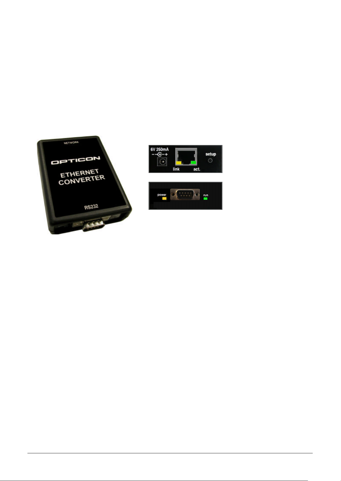
1.1 Detailed view
1.2 Supported Opticon Handheld Terminals
The Ethernet Converter box has been designed as replacement for applications of Opticon Handheld terminal
that make use of TCP/IP dialup connections by 56k modems and GPRS/GSM modems without having to
change the software of the application itself.
Currently the following Opticon Handheld terminals are supported:
§ OPL97xx
§ PHL1700
§ PHL1300
§ PHL2700
§ OPH1003
To be able to use the TCP/IP capabilities of the Ethernet Converter box you'll need to the following TCP/IP
libraries for these terminals:
§ OPL97xx: LMAV020Y or higher (or LNAV020Y for IrDA)
§ PHL1700: CMWV020Y or higher
§ PHL1300: CMWV020Y or higher (or CQWV020Y for IrDA)
§ PHL2700: CMWV020Y or higher (or CQWV020Y for IrDA)
§ OPH1003: XMAV020Y or higher
Notes
§ Older versions of the TCP/IP libraries will also work, so it is not necessary to rebuild existing applications,
however they will work with a slower communication speed!
§ It is recommended to use the latest TCP/IP library available at all times (= currently v.0300)
§ The TCP/IP libraries and further info can be found on the 'C-development kit for Opticon Handheld Terminal'
4 - Opticon Ethernet Converter
Page 5

1.3 Handling Instructions
Temperature conditions
• Do not use in freezing areas.
• Do not use in area’s with temperatures higher than 40°C
• Avoid contact with water.
Shock
• Do not expose the scanner to strong impact, do not throw or drop the box from great heights.
• Do not present mechanical shocks to the product.
• Do not leave the bar code data collector in an area where static charge is accumulated or near devices where
electromagnetic emission is generated.
Maintenance
• There are no user-serviceable parts inside the scanner. So do not try to take it apart.
• In case of serious malfunction, please consult your local dealer or Opticon.
Recycling & Disposal instructions
• The icon on the product or package indicates that the product should not be thrown in the home waste bin.
The product must be recycled as an electronic product. For proper treatment of end-of-life products consult the
section for Environmental care on www.opticon.com.
Opticon Ethernet Converter - 5
Page 6

2 Getting Started
2.1 Connecting the cables and power supply
2.1.1 Power supply
Insert the included 6.0V power supply in the power connector. If the converter box is powered the orange power
indicator will be on and the green 'run' LED will be blinking.
2.1.2 RS232 Cable
If you want to connect an Opticon Handheld terminal or a simple RS232 barcode reader to the Opticon Ethernet
Converter you can use the standard RS232 cable that was included with your Opticon terminal or scanner.
Note:
If you want to replace an existing Internet solution with analog or GSM modems by Opticon Ethernet
Converters, it is possible that you need to add/remove a Null-modem to/from the cable that's currently
connected to the modem or replace the current cable by a standard RS232 cable.
2.1.3 Ethernet cable
Connect an Ethernet cable between your local network and the Ethernet Converter box. If an Ethernet signal is
detected, the orange (link) LED on the connector will be turned on. If any data is received, the green (data) LED
on the connector will blink.
2.2 Configuration of the Ethernet Converter box
Two different kinds of settings can be configured in the Ethernet Converter
§ Serial settings Changing the baud rate (default is 115200bps)
§ Network settings Configuring the local IP, DNS server, Gateway, Subnet mask and DHCP
If the Ethernet network has a DHCP server (DHCP is enabled by default) configuring is often not even
necessary since all required network settings and local IP-address are all received automatically.
If the Ethernet network does not have a DHCP server, you will have to disable DHCP and set the local IP, DNS
server, Gateway and Subnet mask manually.
In total there are 3 different methods to configure the Ethernet Converter. All 3 will be described on the following
pages.
6 - Opticon Ethernet Converter
Page 7

2.2.1 Method 1: Using the System menu via RS232
Connect your Ethernet Converter box to the serial port of a PC or Laptop and open an RS232 monitor (i.e.
Hyperterminal or Appload) using the following serial settings:
§ 115200 baud (8 data bits, no parity, 1 stop bit)
Enter the system menu by powering up the Ethernet box with the set-up button pressed. After that, the following
menu will be shown:
1: Show current settings.
2: Change Board Host Name.
3: Change default IP address.
4: Change default gateway address.
5: Change default subnet mask.
6: Change default DNS server address.
7: Enable DHCP.
8: Disable DHCP.
0: Save & Quit
Enter a menu choice (1-0):
While being in the system menu, pressing the corresponding numbers will give the following results:
1: Show current settings
Settings of the OSE Ethernet-to-RS232 Converter Box
Version: HACV0010
MAC Address: 00-12-6A- xx-xx-xx
Local IP Address: 169.254.254.254
Gateway Address: 169.254.254.1
Subnet mask: 255.255.0.0
DNS server address: 169.169.169.2
DHCP: Enabled
Baudrate: 115200
2: Change Board Host Name
Host Name (OSE_ETHERNETBOX): <enter new host name>
3: Change default IP address
Default IP Address (169.254.254.254): <enter IP address>
4: Change default gateway address
Default Gateway Address (169.254.254.1): <enter IP address>
5: Change default subnet mask
Default Subnet Mask (255.255.0.0): <enter IP Mask>
6: Change default DNS server address
Default DNS Server Address (169.169.169.2): <enter IP address>
7: Enable DHCP
DHCP Enabled.
8: Disable DHCP
DHCP Disabled.
0: Save & Quit
Now running application...
Pressing of set-up button for 4 seconds
All settings have been restored to default. Press '0' to cancel, remove power to confirm.
Opticon Ethernet Converter - 7
Page 8

2.2.2 Method 2: Using AT-commands via RS232
It is also possible to configure the Ethernet box by sending modem (AT-)commands via RS232. You can send
these commands manually via an RS232 monitor (i.e. Hyperterminal or Appload) or for a quicker setup you can
also connect an (RS232) barcode reader and scan configuration barcodes.
The following AT-commands can be send to configure the Ethernet box.
Option Command Example + barcode
Default host name AT+NAME<string 1-16>
Default IP-address AT+IP<address>
Default Gateway IP AT+GATE<address>
Default DNS server IP AT+DNS<address>
Default subnet IP mask AT+MASK<address>
Disable/enable DHCP AT+DHCP<boolean>
Baudrate AT+BAUD<baudrate>
Important notes:
§ All commands must be terminated with a carriage return <CR>
§ Make sure you send the commands at the correct baud rate (default is 115200bps)
§ The review the current settings use the following command: 'AT?'.
§ If a command is accepted the Ethernet box will respond with <CR><LF>OK<CR><LF>
§ If a command is not accepted the Ethernet box will respond with <CR><LF>ERROR<CR><LF>
8 - Opticon Ethernet Converter
Page 9

2.2.3 Method 3: Using the configuration page of the embedded HTML-server
The Ethernet Converter box contains an embedded HTML-server that can be accessed using an Internet
Browser.
To access this HTML-server you need to know the IP-address of the Ethernet box first. You can find the local IP
address of the Ethernet:
1) By using the System menu (see Method 1, only works if DHCP is disabled)
2) By serially sending the 'AT?' modem command (see Method 2)
3) By using an application that listens to UDP port 30303 (only works if DHCP is enabled!)
An example of such an application is the program 'ECB Viewer'. This program can be downloaded at
www.opticon.com at the 'support > download software' 'section.
If DHCP is enabled, a power-up event of an Ethernet box will be shown in this application including its IPaddress and MAC-Address.
Screenshot of 'ECB Viewer'
Opticon Ethernet Converter - 9
Page 10

After retrieving the IP-address (i.e. 192.168.0.2), you can type the address in your Internet browser to see the
following configuration screen or simply double click on the desired Ethernet converter box in 'ECB Viewer'.
To change a configuration value, simply type the desired value in the correct text input field and press the 'Write'
button next to it. After pressing the 'Write' button the current setting should immediately be updated at the
bottom half of the screen.
Important note:
§ Most configurations require the Ethernet box to be restarted before becoming active!
10 - Opticon Ethernet Converter
Page 11

2.3 Establishing a TCP/IP connection with Opticon handheld terminals
Writing an application for the Ethernet converter box is (almost) identical to writing an application with the
TCP/IP library that makes use of a dialup modem.
For more information about writing applications with the TCP/IP library and example applications, please refer to
the manuals of the 'TCP/IP library for Opticon Handheld terminals'.
The Ethernet converter box accepts almost all AT-modem commands. However there are few additional ATcommands that are different or additional:
ATD… or ATDT… Establish a connection between an Opticon handheld terminal (with TCP/IP library)
and an Ethernet Converter box.
Response:
<CR><LF>CONNECT<CR><LF>
<PPP frame><PPP frame>
Normally the ATD(T)-command should be made by the connect()-function of the
TCP/IP library after which the application continues the TCP/IP session.
ATIx Returns the current software version
AT? Shows all current settings
ATV0 Normal response codes: i.e. OK / ERROR
ATV2 Barcode reader response codes, in case an Opticon barcode reader is used to
configure the Ethernet box with AT-commands. <ESC>B or <ESC>E that will result in
a good or bad read sound.
AT+CPIN? Returns: +CPIN: READY\r\n\r\nOK\r\n for GSM/GPRS modem simulation
AT+DISCOVERY Returns IP and MAC address of all Ethernet boxes that are connected to the local
Ethernet.
Example response:
Searching...
192.168.0.2 00-12-6A-00-12-34 OSE_ETHERNETBOX
Done
AT+BAUDxxxxx Configure a baud rate between 4800 and 230400bps (the OK response might be
returned at the new baud rate!)
AT+RESET (Software) Resets the Ethernet-to-RS232 converter box
Note:
§ Disconnect a connection by sending '+++' with a 1-second pause before and after the command.
Opticon Ethernet Converter - 11
Page 12

2.4 Establishing a (virtual) RS232 connection over Ethernet
Using two Ethernet Converter boxes it is possible to establish a virtual RS232 connection over Ethernet to
transmit and receive serial data to and from a remote location as if it's connected to a very long serial cable.
Below it will be explained how it works and how it can be used.
2.4.1 Supported protocols
To transmit data over the Ethernet 2 different protocols can be used: UDP (port and TCP. They both have
advantages and disadvantages depending on reliability and maximum throughput.
When using UDP, no handshaking is used so data can be lost due to lost packages on the network. It is
possible to add an extra protocol like Xmodem, NetO or a simple handshaking mechanism to fix that problem.
When using TCP, handshaking is used, which makes the maximum throughput low, therefor data can be lost
due to buffer overflows since the serial throughput is faster than the TCP throughput over the Ethernet.
UDP TCP
Maximum throughput (at 115200) streaming (at 115200 BPS) < 400 byte blocks with intervals
Handshaking No Yes
This means that if you use the virtual RS232 connection for:
§ Transmitting / receiving of small data packages (i.e. barcodes) TCP is more reliable.
§ Transmitting / receiving large quantities of data UDP is more reliable
Notes:
§ Serial over TCP uses port 31313, serial over UDP uses port 31314
2.4.2 Finding remote Ethernet Converters
To find other Ethernet Converter boxes the following AT-command is available
AT+DISCOVERY Returns IP and MAC addresses of all Ethernet boxes that are connected to
the local Ethernet.
Example of the search result:
Searching...
192.168.0.2 00-12-6A-00-12-34 OSE_ETHERNETBOX
192.168.0.14 00-12-6A-00-00-12 OSE_ETHERNETBOX2
Done
2.4.3 Connecting to remote Ethernet Converters
To establish a virtual RS232 connection the following AT-commands are available:
UDP ATDudp://xxx.xxx.xxx.xxxx
or
ATDudp://yy-yy-yy-yy-yy-yy
TCP ATDtcp://xxx.xxx.xxx.xxxx
or
ATDtcp://yy-yy-yy-yy-yy-yy
Where xxx.xxx.xxx.xxx is the IP address of the remote Ethernet box
or
Where yy-yy-yy-yy-yy-yy is the MAC address of the Ethernet box
Where xxx.xxx.xxx.xxx is the IP address of the remote Ethernet box
or
Where yy-yy-yy-yy-yy-yy is the MAC address of the Ethernet box
If the connection was established the Ethernet box will respond with:
CONNECT xxx.xxx.xxx.xxx (where xxx is the IP-address)
Note:
§ Disconnect a connection by sending '+++' with a 1-second pause before and after the command.
12 - Opticon Ethernet Converter
 Loading...