

Page 1

fixed mount laser scanner
User’s Manual DFM 1000
Page 2

U
SER’S MANUAL
DFM1000
Limited warranty and disclaimers
By opening the package of this product you agree to
become bound by the liability and warranty conditions
as described below.
Under all circumstances this manual should be read
attentively, before installing and or using the product.
In no event, Opticon Sensors Europe will be liable for
any direct, indirect, consequential or incidental
damages arising out of use or inability to use both
the hardware and software, even if Opticon has been
informed about the possibility of such damages.
CAUTION:This user’s manual may be revised or
withdrawn at any time without prior notice.
Copyright 2002, Opticon Sensors Europe B.V.
All rights reserved.
This manual may not, in whole or in part, be copied,
photocopied, reproduced, translated or converted to
any electronic or machine readable form without
prior written consent of Opticon Sensors Europe.
DFM-ver2 / printed 02-02
A serial number appears on all Opticon products.
This official registration number is strictly related to
the device purchased. Make sure that the serial
number appearing on your Opticon device has not
been removed.Servicing by our Repair Depar tment
can only be carried out under warranty.
All Opticon products are warranted for a period of
one year after purchase, covering defects in material
and workmanship.Opticon will repair or, at its opinion,
replace products that prove to be defective in material
or workmanship under proper use during the warranty
period.
Opticon will not be liable in case modifications are
made by the customer.In such case the standard
repair charge will be applicable.The standard charge
for repair will also be applicable in case no defect is
found at all.These rules also apply for products that
are still under warranty. Therefore, you are advised to
have the product specifications always at hand.
Trademarks used are property of their respective
owners
Page 3

CONTENTS
page
U
SER’S MANUAL
DFM1000
page
1 INTRODUCTION 4
2 INSTALLATION 4
2.1 UNPACKING 4
2.2 DETAILED VIEW
2.2.1 Dimensions of the scanner 5
2.2.2 Details of the scanner 5
2.3 H
ANDLING PRECAUTIONS 6
2.4 MOUNTING 7
2.4.1 Place for mounting 7
2.4.2 Scanning distance and angles 7
2.4.3 Mounting suggestions 8
2.5 POWER CONNECTION 8
2.5.1 Power supply and connection
to the host 9
2.5.2 Grounding 9
3 OPERATION OF THE TERMINAL 10
3.1 F
3.2 C
UNCTIONING 10
HARACTERISTICS 10
3.2.1 Automatic triggering 10
3.2.2 Adjustable scan width 10
3.2.3 Read modes 10
3.2.4 Check mode 11
3.2.5 Formatting the bar code data 11
3.2.6 LED indicator 11
3.2.7 Buzzer signal 11
3.2.8 Serial communication 11
3.2.9 Bar code polarity 11
3.2.10 (No) Decode signal 11
3.2.11 (No) Decode message 11
3.2.12 Trigger signal 11
3.2.13 Trigger message 11
3.2.14 Data formatting options 11
5 PIN OUT 13
6 SPECIFICATIONS 14
6.1. Electrical specifications 14
6.2 Optical specifications 14
6.3 Supported symbologies 14
5
6.4 Functionality 14
6.5 Environmental specifications 15
6.6 Physical specifications 15
7 TROUBLESHOOTING 16
8 PRODUCT ORDERING
INFORMATION 18
9 TEST LABELS 19
4 WORKING WITH THE SCANNER 12
4.1 Scan position 12
4.2 Reading the bar codes 12
3
Page 4
U
Double
Sided
SER’S MANUAL
DFM1000
1
The DFM1000 bar code laser scanner has
been specifically developed for industrial use.
The rugged metal housing can easily be fixed
through an adapter on a DIN rail.
The high scan rate makes the scanner
extremely suitable for mounting on a conveyor
belt.
When the DFM1000 is connected to the host,
it will operate as a self supporting scanner.To
integrate the scanner to many industrial applications and other devices, it is provided with
several I/O lines which can be configured by
the user .
The general use and functioning of the scanner will be described in this manual. For
instructions about applications please consult
the documentation of that software.
Read this manual carefully before using
the terminal, to maximise the efficiency of
this scanner.
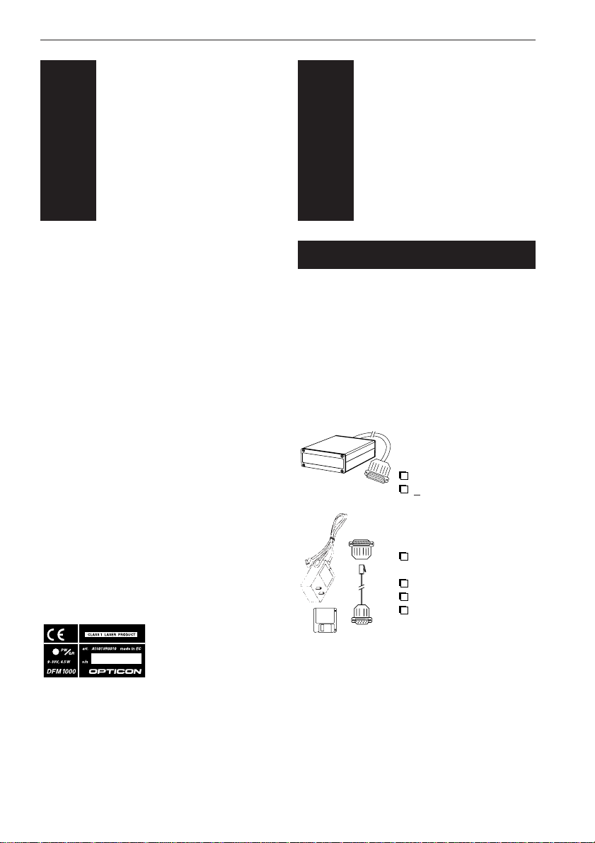
Do not remove the scanner label.
includes information about the power supply
to the scanner and a serial number.Do not
remove it.
INTRODUCTION
On the back housing
of every scanner you
will find a label.The
label is attached by
the manufacturer and
2
INSTALLATION
2.1 UNPACKING
When you remove the packing, please check
for any physical damage. We recommend that
you save all packing material, as it should be
used whenever you need to ship your terminal
(eg. for service). Damage due to improper
repacking is not covered by the warranty.
Make sure that all of the items shown below are
present. If there are any missing parts please
contact your supplier.
DFM1000:
Laser scanner:
including
DB25 male connector
+ 1,5 m cable
OPTIONAL:
Configuration kit:
including
configuration disc with
configuration software
RS232 adapter
RS232 DB9 cable
12V power supply
4
Page 5
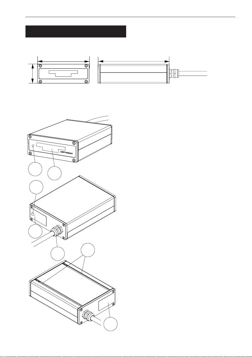
39 mm
105 mm
143 mm
1
2
3
4
5
6
7
2.2 DETAILED VIEW
2.2.1
Dimensions of the scanner
2.2.2
Details of the scanner
U
SER’S MANUAL
1. Reading window
Reads bar codes
Never obstruct this window.
2. Autotrigger aperture
It is very important that the autotrigger
aperture always can operate free.
Never obstruct this part of the window.
3. LED indicator
Power LED orange (default)
Good Read LED green (default)
4. Buzzer/Beeper
A single tone beep indicates results as
defined by the user.
DFM1000
5. Connector
For RS 232 and RS 485 connection,
power supply and configurable I/O lines
6. Mounting slot
Slot for fixed mounting or for DIN-rail
adapter, with adjustable bolts and nuts.
7. Scanner label
Do not remove it
5
Page 6
U
!
COMPUTER:
- RS 232 port
- parallel port
DFM1000:
DB25 male
connector
!
SER’S MANUAL
DFM1000
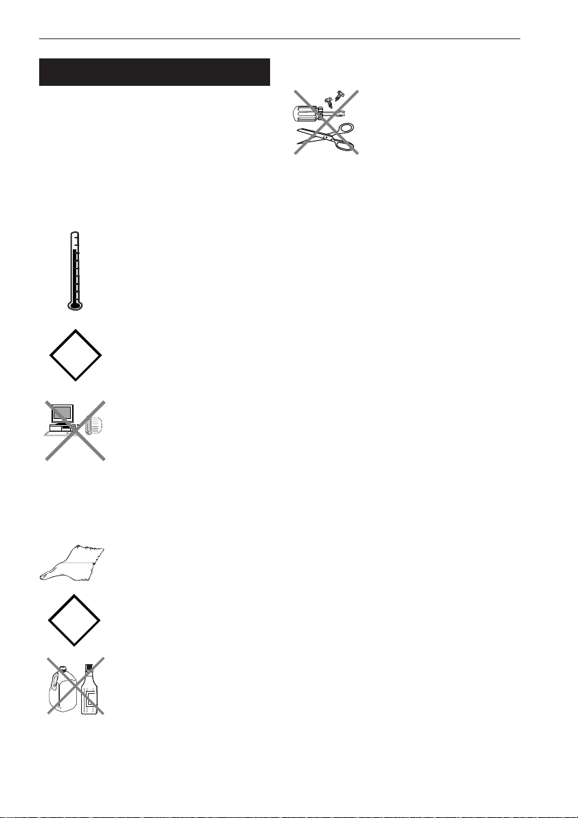
2.3 HANDLING PRECAUTIONS
The DFM1000 is water-, dust- and schock
resistant according to the specifications in the
appendix, but the scanner consists of minute
electronic parts. To avoid malfunctioning and
to ensure years of trouble free operation, we
want tot state you the precautions below. Pay
attention to the following:
Use of the DFM1000
For long periods, do not use
or leave the scanner in area’s
that are exposed to extreme
heat that is higher than 50 oC
- like direct sunlight, or near a
heater.Also do not expose
the scanner to freezing area’s.
Do not subject the scanner to
very strong impact, do not
throw or drop the scanner
from large heights.
Do not plug the DB25 male
connector of the scanner
directly into the RS232 or
parallel port from computer
(or printer). The pinout is not
compatible and will cause
damage without using an
adapter.
Maintenance/Troubles
There are no user-serviceable
parts inside the terminal or
the cradle. So do not try to
take it apart. Opticon will not
be liable for any damage
caused by the customer.
In case of malfunction that can not be solved
by the trouble-shooting instruction in the
appendix, please consult our service
department.
Cleaning of the DFM1000
Clean the exterior by wiping it
with a soft, lightly moist cloth.
Do not use a high pressure
cleaning method.
To clean the window use nonabresive liquids.
6
Page 7

U
!
!
5 mm
75 mm
90 mm
130 mm
155 mm
270 mm
360 mm
425 mm
520 mm
750 mm
0.15 (6
mil)
0.127 (5
mil)
0.25 (10 mil)
0.33 (13 mil)
0.39 (15.6 mil)
0.5 (20 mil)
1.0 (40 mil)
Resolution
at PCS 0.9
Reading width and reading distance of DFM1000
DFM1000
Reading
distance
Scan width (mm)
050100
150
200
250
300
50
100
150
200
250
300
0 - 60
0
0 - 50
0
3 - 80
0
5 - 85
0
Reading angles of DFM1000
Pitch angle
Skew angle
= Reading area
= NO reading
SER’S MANUAL
DFM1000
2.4 MOUNTING
Follow the next steps to make your scanner
ready for installation in a system.
2.4.1.
Place for mounting
Avoid sunlight and/or bright light or
aser light from other devices.
Place the scanner in such a way that
the reading window and the autotrigger
aperture can operate free.
Wall mounting instructions
To ensure optimum reading capacity,
estimate the scan distance of the scanner,
as described in this chapter.
Pay attention to the pitch and skew angles,
as described in this chapter.
Avoid excessive angles.
2.4.2.
Scanning distance and angles
Use the diagram below to see which reading
distance should be used related to the bar
code resolution.
Use the other diagram to adjust your scanner
to the right angle.
7
Page 8

!!!!!
U
!!!
KEEP THE
BOLTS
LOCKED
NON-MOUNTING
1
2
BEFORE
MOUNTING
SER’S MANUAL
2.4.3.
The DFM1000 can be placed on a flat surface
or can be permanently mounted (fixed).
The bottom of the scanner is provided with 2
slots with adjustable bolts and nuts for mounting
on e.g. a DIN-rail.
In every mounting situtation make
sure that the bottom of the scanner
is positioned under straight angle.
When you do not fix the scanner,do
not loosen the
bolts.
To mount
the scanner on a DIN-rail, we
recommend you to use a DIN-rail
adapter. (as shown in example below)
DFM1000
Mounting suggestions
2.5 POWER CONNECTION
Exercise caution at all times when
working with AC and DC-powered
equipment.
Turn off your devices before
installation.
We advise you to connect the
DFM1000 to your host as shown in the
figures in this chapter.
Before connecting the additional
communication cables, take notice of
the pin-out specifications (chapter 5)
Do not plug the DB25 male connector of
the scanner directly into the RS232 or
parallel port from computer (or printer).
The pinout is not compatible and will
cause damage without using an adapter.
Follow the next instructions to mount the
scanner.
First remove the bolts.(ref. 1)
When an adapter for mounting is used,
take the adapter to fix the scanner.
Adjust the nuts to the position that is
needed for mounting. (ref. 2)
Screw the bolts into the nuts until
the scanner is secured.
8
Minimize noise interference and
ground loops.Therefore pay attention
to the grounding diagram.
Page 9

U
COMPUTER:
- RS 232 port
- parallel port
DFM1000:
DB25 male
connector
9-33 V DC
DB25 MALE
(from scanner)
6P6
MOD.
JACK
TO PARALLEL
PORT OF PC
TO HOST
DB25
FEMALE
RS 232
ADAPTER
ALTERNATIVE
CONFIGURATION
MODE
DFM1000 Wiring Diagram
CONFIGURATION
ADAPTOR
DB25 MALE
(from scanner)
COMMUNICATION
AND CONFIGURATION
MODE
POWER
SUPPLY
9-33 V DC
POWER
SUPPLY
8P8
MOD.
JACK
DB9
FEMALE
EARTH GROUND
SHIELDING
COMMUNICATION CABLE
DFM1000 Grounding Diagram
SCANNER HOST
SER’S MANUAL
DFM1000
For configuration of the DFM100 an additional
configuration kit is available.You are strictly
recommended to use this kit for optimalization.
The scanner should work according to the
default options.Other options have to be set
by the user, through the optional configuration
kit.
2.5.1
Power supply and
connection to the host.
The wiring diagram on this page gives some
suggestions to connect the scanner correctly.
Do not plug the DB25 male
connector of the scanner
directly into the RS232 or
parallel port from computer
(or printer). The pinout is not
compatible and will cause
damage without using an
adapter.
Connect the scanner to the host.
Connect power supply to the scanner
(9-33V DC unregulated + 5%)
Connect power to the host.
Scanner beeps.
Default setting; Power LED(back side
scanner) should light up in orange colour.
Scan an EAN/UPC bar code label from the
test labels in chapter 9.
Scanner beeps.
Default setting;Good Read LED (back side
scanner) flash green shortly.
Data is sent to the host.
Default communication settings:
RS232 (9600,N,8,1)
Check data at the host.
2.5.2
Grounding
See grounding diagram.
Make sure the shielding is grounded only
to earth ground at the host. The shielding
connection to the scanner from the host
should not be connected ot the shielding
of the scanner.
Make sure that the frame ground of the
scanner is connected to the earth ground.
Make sure that the host, the scanner and
their power supplies are connected to a
common earth ground.
9
Page 10

U
SER’S MANUAL
3
DFM1000
OPERATION OF
THE TERMINAL
3.2 CHARACTERISTICS
The DFM1000 is equipped with different characteristics. Some characteristics are already
preset by Opticon and have a function.A number of characteristics can be enabled or disabled by the user through configuration software and the configuration cable.In this chapter we give you some examaples of the scanners many functions.
3.2.1.
Automatic triggering
3.1 FUNCTIONING
The DFM1000 will detect the bar code with a
single line laser beam.The reflected light will
be picked up and converted by the sensor to
an electric signal, which is representing the
bar code label.The decoder will recognise the
bar code symbology and extract teh information.The resulting dta is sent to the host that
is connected to the scanner.
The presence of a bar code will be recognised
by the autotrigger function of the scanner,
meaning that the laser beam is activated as
soon as an object moves towards the reding
window of the laser scanner.When the user
prefers to use an external trigger, it is possible
to switch off the autotrigger function and connect an external trigger to the scanner.
Automatic triggering is a default function of the
scanner.When the user prefers to use an
external trigger, it is possible to switch off the
autotrigger funcation and connect an external
trigger to the scanner.
3.2.2.
Adjustable scan width
If another scan width than the default scan
width is needed, it is possible to adjust the
reading width of the scan pattern settings.
3.2.3.
Read modes
By setting an other read mode the use has
the ability to activate the read operation in the
that way that is the most convenient. the scanner is provided with 3 read modes, which can
be enabled or disabled by the user;
Single read mode:
After a bar code is successfully decoded, the
laser is switched off, and the user has to
retrigger the scanner in order to scan the next
label.
Multiple read mode:
After a bar code is decoded successfully the
laser stays on, allowing the user to read
another bar code. A bar code is only transmitted once, regardless the number of times the
scanner reads it. Only when the scanner could
not decode a bar code for a selected time, the
laser is shut off.
10
Continous read mode:
This is a test mode, in which every decoded
bar code is transmitted whether it is the same
or not.
Page 11

3.2.4.
Check mode
3.2.9.
Bar code polarity
U
SER’S MANUAL
DFM1000
To ensure the bar code is correctly decoded,
there are 2 options, to be enabled by the user.
Redundant reading:
A bar code is transmitted only when it is
decoded successfully for a selected number of
times.This number can be set by the user.
Check digit calucation:
A calculation of the digits of the bar code
should correspond with the check digit.
3.2.5.
Formatting the bar code data
When reading a bar code, some formatting
can be done by the scanner.the user can
configure this. Some examples are:
Some of the options many not be valid for all symbologies.
Enable required symbologies, disable all others
Transmit start/stop characters on/off
Transmit check digit on/off
Case conversion
Add character(s) as prefix and suffix
Translate bar codes, like full ASCII code 39,
ISBN, EAN etc.
3.2.6.
LED indicator
The LED indicator can light up red or green.
They can light up as a separate colour or
together (shown as orange light).
As a default setting the indicator is defined as
a Power LED (orange) and as a Good Read
LED (green). The duration that it lights after a
successful decode or an other definition of the
setting can be configured by the user.
3.2.7.
Buzzer signal
The buzzer signal, i.e.single tone beepe can
be used for a good read bar code or as an
error signal for a failed transmission.The
definition of use, frequency and duration of the
beeper can be adjusted by the user.
3.2.8.
Serial communication
For direct communication between the
scanner and the host the scanner is provided
with RS232 interface.Other interfaces are
available on request.
The laser scanner is able to red positive and
negative labels, for both black or coloured
labels.The following bar code reading options
are available:
Black on white
White on black
3.2.10.
(No) Decode signal
Except for the Good Read LED, its is possible
to indicate the results of bar code reading and
decoding by a pulse signal to the host.
Dedoce pulse: the bar code is read and
decoded correctly
No Decode pulse: during the read time no
bar code is detected or could not be
decoded
3.2.11.
(No) Decode message
When the read time expires and the scanner
did not detect or decode a bar code, a
configurable string of max. 50 characters can
be transmitted to the host.
(supported from software version DCCV0103 or higher)
3.2.12.
Trigger signal
If internal trigger is activated, a positive or
negative pulse is generated.This option can
be set for each symbology separately or for all
symbologies.
(supported from software version DCCV0103 or higher)
3.2.13.
Trigger message
A configurable string of max. 50 characters
can be sent to the host when the scanner is
triggered.
(supported from software version DCCV0104 or higher)
3.2.14.
Data formatting options
Data can be manipulated before the data is
transmitted to the host.The data manipulation
is performed unconditionally. See configuration
disc for the specifications.
(supported from software version DCCV0110 or higher)
11
Page 12

U
!
!
SER’S MANUAL
DFM1000
WORKING WITH
4
The DFM1000 laser scanner is a Class I laser
product conforming to strictest laser safety
standards. However, we recommend that you
avoid looking directly into the laser beam emitter, or pointing the laser beam directly into
someone’s eyes.
THE SCANNER
Take care of the handling precautions.
Make sure that the scanner is installed
according to the installation
instructions.
4.1
Scan Position
The bar code label of the product should be
visible in the field of the scanner pattern.
When the scanner is not able to decode the
bar code label of the product, it is possible to
change some settings through configuration
software to achieve a better scan width.
4.2
Reading the bar codes
Depending on the bar code size and bar
code resolution we recommend you the
scan distances as described in the
diagram of chapter 2.4. of this manual.
Take care that the bar code side of the
product appears in the front of the reading
window.
Pay attention to the reading angles of the
scanner, as shown in chapter 2.4.of this
manual.The scanner should read the bar
codes in the reading area.
If you have problems with the read operation,
pay attention to the following:
Check if the scanner is not oblique
mounted.
Check if the scanner is able to decode the
bar code, referring to the reading angles.
Check if the position of the bar code label
is correct.
Scan one of the test labels of chapter 9. If
the test label is read correctly, check the
readability of the bar code used.
12
Page 13

U
!
PIN
1
2
3
4
5
6
7
8
9
10
11
12
13
14
15
16
17
18
19
20
21
22
23
24
25
COLOR
BROWN
RED
ORANGE
PINK
PIN 1 - 4 : RS485 INTERFACE
YELLOW
GREEN
LIGHT GREEN
BLUE
LIGHT BLUE
PIN 6 - 9 : RS232 INTERFACE
PURPLE
GREY
WHITE
BLACK
BROWN - BLACK
RED - BLACK
PIN 14 : FOR FUTURE EXPANSION
ORANGE - BLACK
PINK - BLACK
YELLOW - BLACK
GREEN - BLACK
PIN 16 - 19 : FOR FUTURE EXPANSION
LIGHT GREEN - BLACK
BLUE - BLACK
LIGHT BLUE - BLACK
PURPLE - BLACK
GREY - BLACK
WHITE - BLACK
FUNCTION
TRTR+
TT+
not connected
RTS
CTS
RxD
TxD
SUPPLY VOLTAGE
9-33 V DC
UNREGULATED
(< 1 V
SIGNAL GROUND
(NO)READ OUTPUT
TTL - sink or source
max. 4mA
TRIGGER INPUT
High level voltage: 2-15 V
Low level voltage : 0-0.8 V
I/O 1
TRIGGER OUTPUT
TTL - sink or source
max. 4mA
I/O 2
I/O 3
I/O 4
I/O 5
I/OE 1
I/OE 2
I/OE 3
not connected
+5 V DC OUTPUT
(MAX. 100mA)
FRAME GROUND
p-p
ripple)
SER’S MANUAL
DFM1000
5
PIN-OUT
The pinout description mentioned in this chapter must be used to connect the DFM1000
scanner to the host.
The pinout of the DB25 male
connector is NOT compatible with
standards for RS232.
Do not plug the DB25 male connector of the
scanner directly into the RS232 or parallel
port from computer (or printer). The pinout is
not compatible and will cause damage without
using an adapter.
13
Page 14

U
SER’S MANUAL
6
6.1
Electrical specifications
Voltage requirement 9-33V DC unregulated,
Power consumption max.4.5 Watt.
6.2
Optical specifications
Light source 670 nm visible laser diode
Deflection system rotating polygon
Scan rate 1000 scans/sec
Decode rate max. 1000 decodes/sec
DFM1000
SPECIFICATIONS
less than 1V
(10 facets)
p-p
ripple
6.3
Supported symbologies
Codabar incl. ABC, CX
Code 39
Code 93 (version DCCV0111 or higher)
Code 128
EAN 8 incl. +2,+5
EAN 13 incl. +2,+5
IATA
Industrial 2of5
Interleaved 2of5
ISBN
ISSN
Laetus
Matrix 2of5
Italian Pharmaceutical
MSI/ Plessey
UK/ Plessey
S-Code
Telepen
UPC-A incl. +2,+5
UPC-E incl. +2,+5
6.4
Functionality
configurable I/O’s Trigger input
Trigger modes External input
Trigger output
Noread output
Auto trigger
Spot velocity 215 m/sec at 100 mm
Reading width max.140mm at 100mm
max.300mm at 300mm
Min. resolution
at PCS 0,9 0.127 mm (5 mil)
Min PCS values 0.30
Depth of field max. 750 mm
at PCS 0.9 (resolution=1mm)
14
Configuration via download cable
and/or OSEMENU
software
Interfaces RS232
Upgradeability The software can easily
be upgraded using
OSEMENU
Page 15

6.5
Environmental specifications
U
SER’S MANUAL
DFM1000
Temperature 0 - 50 oC in operation
-20 - 60 oC in storage
Humidity 5 - 95 % in operation
(non condensing) 5 - 95 % in storage
Emission According to EN50081,
part 1 & 2
Immunity According to EN50082,
part 1 & 2
Protection against
dust and moisture According to IEC529,IP
54
Safety, Laser class According to IEC825,
Class I laserproduct
6.6
Physical specifications
Dimensions (l x w x h) 143 x 105 x 39
mm
Case material aluminium - anodised
Weight 780g
Standard connector DB25 - male (1.5m cable)
15
Page 16

U
?????
?
?
SER’S MANUAL
DFM1000
Scanner does not function.
The DB25 male connector of the
DFM1000 is not RS232 compatible!
Check if the scanner is connected as
advised in the wiring diagram
(chapter 2.5)
TROUBLE
7
This chapter contains information on solving
problems you may encounter when using the
terminal and/or cradle. If problems occur, first
carry out some general checks, before verifying
the problem with the descriptions in this chapter.
General checks:
Make sure everything is installed properly
Check the power supply of all devices
Is the read window of the scanner clean?
Are the bar code labels readable, eg. not
damaged or poorly printed?
Scan a test label of chapter 9. If the test
label is read correctly, check the readability
of the bar code used.
If the equipment still does not work after these
checks have been performed, please verify if
one of the problems described in this chapter
applies to the problem you have with the
scanner.
It is possible that you may not solve the
problems, despite our descriptions. In this
instance, please contact your dealer or
Opticon.
When the terminal needs to be repaired,
please ensure that the label with the serial
number is still present. If sending the terminal
or cradle, please use the original packing to
minimise the chances of damage.
SHOOTING
Good Read LED is off.
Check the power supply.
If faulty power supply is used, replace the
power supply.
Check the cables.
If faulty cables are used, replace the
cables.
Scanner does not beep at startup.
Motor does not or hardly rotate.
Power LED is on.
The power supply is not capable of
powering the scaner.Replace the power
supply.
Laser goes off.
Motor seems to be slower.
Buzzer keeps beeping.
Motor could not be regulated to its desired
speed. Restart the scanner. If the porblem
persists, contact your local dealer.
Scanner does not read very well anymore.
Scanner window is dirty.
Clean window with clean damp flintfree
cloth. Do not use abrassive liquids.
Autotrigger does not react very well.
Autotrigger aperture is dirty.
Clean the scanner window (autotrigger
aperture) with clean damp flintfree
cloth. Do not use abrassive liquids.
Autotrigger aperture is obstructed.
Take care that the autotrigger aperture
always can operate free.
16
Page 17

Scanner seems to work but the bar code
???
?
?
can not be read.
The bar code symbology to be read is
disabled.
Enable the bar code symbology in the
software.
Of a certain bar code symbology, some bar
codes can be read while other can not be
read.
Some bar codes contain a ‘check digit’.
Disable ‘check digit’ for the involved bar
code symbology.
Fixed length is set for the involved bar
code symbology.
Adjust or remove the fixed length check.
Strange characters are received at host.
Baudrate, databits, stop or parity do not
match.
Compare and match these settings
between host and scanner.
Default communication settings:
9600 baudrate
No parity
8 data bits
1 stop bit
U
SER’S MANUAL
DFM1000
No data is received at host and scanner.
No handshake signals, while
handshaking is selected.
Compare and match handshake settings
for host and scanner.
17
Page 18

U
SER’S MANUAL
DFM1000
PRODUCT
ORDERING
8
Scanner
DFM-1000 laser scanner A15013R0010
including
DB25 male connector
+ 1,5 m cable
Additional
Configuration kit for DFM A83200N0010
including
configuration disc with
configuration software
RS232 adapter
RS232 DB9 cable
12V power supply
INFORMATION
Article Code
18
Page 19

U
!
!
0 071589 812308
9
780123 456786
>
( 0123456789 )
7 376221 357463
12345
*C+O+D+E 39*
( Code 39 )
*V2GZD9*
( 908557705 )
SER’S MANUAL
UPC A [default]
DFM1000
TEST
9
LABELS
Default labels
In the default mode the scanner
will only read the UPC and EAN labels
without add-on.
Other labels
Before testing one of the other labels,
first activate the right bar code symbology
in the configuration software of the
DFM1000.
EAN 13 [default]
( ISBN)
EAN 13 ADDON 5
Code 39
( Code 39 FULL ASCII )
( Italian Pharmaceutical )
Code 39
19
Page 20

U
0123456789
0123456784
Telepen
( 57748174857483 )
0123456789
( ]C10123456789 )
SER’S MANUAL
DFM1000
Industrial 2 of 5 (without CD)
Interleaved 2 of 5 (with CD)
with bearer bars
Telepen ASCII
( Telepen numeric )
Code 128 Code C
( EAN 128 )
Opticon Article Code
O0225000010
20
 Loading...