

Page 1

INST No. INE-459-0P2CE Ver. 1.11
◆
Request to the operator of the thermometer
This instruction manual describes the maintenance of the thermometer, too.
Keep this instruction manual with the thermometer.
If you have unclear points or need technical assistance, please contact your sales agent
of Optex.
Notices
1. The information in this manual is subject to change without notice and does not represent
a commitment on the part of Optex.
2. No part of this manual may be reproduced or transmitted in any form or by any means, electronic
or mechanical, including photocopying and recording, for any purpose other than the purchaser's
personal use without permission of Optex.
3. Optex shall not be liable for any operation results.
Please read this instruction manual for using the thermometer correctly and safely.
PORTABLE
NON-CONTACT THERMOMETER
THERMO-HUNTER
Model: VF-3000
Always keep this instruction manual with this thermometer.
Please be sure to deliver this instruction manual to a person who
uses this thermometer.
Request and notices
Page 2

INST No.INE-459-0P2CE Ver. 1.11
-C1-
To use the thermometer correctly and safely, please keep the following safety measures for the
operation and storage of the thermometer.
This instruction manual is for the thermometer with the software version 1.11.
The software version of your thermometer is indicated in the label on the front side.
(Ref to [3.1. Views]).
1. Working conditions and environment
Make sure to press any keys until you hear an audible beep. (Except for some operations)
∙ The thermometer is designed as a portable type. Use a tripod or a simple type universal head for
long term or fixed mounting measurement.
∙ The working temperature range of the thermometer is 0(32ºF) to 50°C (122ºF). (No dew
condensation)
∙ Do not use the thermometer in dusty places, etc. Remove dust after using it. (For the cleaning of
cover glass, refer to [7.3 Cleaning of objective glass] and, for the cleaning of external display and
eyepiece cover, refer to [7.4 Cleaning of external display and eyepiece cover].)
∙ Be careful not to give vibration or impact to the thermometer.
∙ When the thermometer is not used, take out batteries from it to prevent battery exhaustion.
∙ For avoiding battery exhaustion, an auto-power-off function is built in the thermometer. If no key
is pressed for 15 seconds in the hold mode, the power supply is automatically turned off.
∙ Avoid measuring shiny objects. Shiny objects reflect surrounding temperatures. The emissivity
rate of the thermometer can be adjusted to compensate for this problem.
2. Storage
∙ Do not store the thermometer in hot and humid places. Make sure to store the thermometer with
the lens cap. Recommend to store the thermometer in room temperature with a dry pill.
∙ Do not leave the thermometer in a car or its trunk room since the inside temperature will be
extremely high in summer. The thermometer may have troubles.
∙ When the thermometer is not used for 2 weeks or more, take out the batteries from it. Otherwise,
the thermometer may be damaged by liquid leakage of the batteries.
∙ When the thermometer has any trouble, please contact to your sales agent of Optex.
3. Symbols in this instruction manual
The symbols shown below are used depending on important degrees for using the thermometer
safely and avoiding unexpected situations.
Important
degree
Symbols Contents
1
This symbol is attached to a title for the sentence with .
2
For avoiding dangerous accidents (may cause death or serious injury)
like as electrical shock, fires, or troubles/damages of the thermometer.
3
For avoiding injury or in physical damage to the thermometer.
4
Information that we suggest to read carefully.
5
Information that you can use as a reference.
!
Warning
Warning
Caution
Reference
Remarks
!
Software Ver. 1.11
Preface
Page 3

INST No.INE-459-0P2CE Ver. 1.11
-C2-
◆ Please use the thermometer correctly by keeping the following items.
In addition, please read this instruction manual carefully and keep it at the place where you
can access easily.
The mark indicates prohibited operations.
Warning (May cause death or serious injury)
Make sure not see the sun through the viewfinder of the thermometer.
It may cause becoming blind.
Never directly face the objective lens to the sun to protect the detecting element.
For the measurement of high temperature objects, refer to the clause of [5.3 Cautions
on measurement].
Never operate the thermometer in places where combustible or volatile gas exists.
It is extremely dangerous to use the thermometer in such environment.
Never put the batteries into fire, or never charge, short-circuit, heat or disassembly
the batteries.
Breaking or heating of the batteries may cause fire or injury.
Never use the thermometer if it has been broken, smoking or nasty smelling.
These may cause fire. When the thermometer is broken, smoking, or nasty smelling,
turn the power supply switch off at once and take out the batteries from the
thermometer, and contact to your sales agent of Optex.
Caution(May cause injury or physical damage)
Do not use other batteries than the batteries specified.
Load the batteries so that their polarities meet the polarity marks on the battery case.
Different polarities may cause fire, injury or damage by burst or liquid leakage of the
batteries.
Do not walk while sighting through the viewfinder of the thermometer.
It may cause accidents like as falling down.
Never take the thermometer apart or convert it.
These may cause trouble and danger.
Read the entire contents in this instruction manual to have the thermometer function
perfectly.
Dispose the batteries used to places specified with the disposal procedure specified.
!
!
!
!
! ! ! !
!
!
! !
Software Ver. 1.11
Warnings and Cautions
Page 4

INST No.INE-459-0P2CE Ver. 1.11
-C3-
CONTENTS
1. Introduction··················································1
1.1 General························································1
2. Model and accessories ·································1
2.1 Model··························································1
2.2 Accessories ·················································1
3. Names and functions of
component parts··························2
3.1 V iews··························································2
3.2 Functions ····················································2
3.3 External Display ·········································3
3.4 V iewfinder··················································3
3.5 Functions of keys········································3
3.6 Markers·······················································3
4. Preparation for measurement·····················4
4.1 Loading batteries········································· 4
4.2 Distance and diameter································· 4
4.3 T ar geting·····················································5
5. Measuring·····················································6
5.1 Standard measurement mode ······················6
5.2 Continuous measurement mode··················6
5.2.1 Start of continuous measurement·············6
5.2.2 Cancellation of continuous
measurement···········································7
5.3 Caution on measurement·····························7
5.4 Emissivity rate setting·································8
5.5 Measurement mode selections ····················8
5.5.1 Signal modulation mode selection············8
5.5.2 T emperatur e unit selection·······················9
5.5.3 2-color type/single color type selection··10
5.6 Measurement mode settings······················10
5.6.1 Low temperature alarm setting···············10
5.6.2 High temperature alarm setting··············11
5.6.3 Modulation value setting························11
5.6.3-1) Modulation time constant setting
(for “dLEy” selected)·····11
5.6.3-2) Damping degree setting
(for “PEAk” selected)·····11
6. Temperature data storage·······················12
6.1 Data storage mode ································· 12
6.2 Data storage number setting and
recalling of stored data········· 14
6.2.1 Data storage number setting················ 14
6.2.2 Recalling of stored data ······················ 15
6.3 Memory full··········································· 16
6.4 Erasing all stored data···························· 16
7. Maintenance and check··························17
7.1 Self-diagnostic function························· 17
7.2 Storage ··················································· 17
7.3 Cleaning of objective lens······················ 17
7.4 Cleaning of external display and
eyepiece cover······ 17
8. List of starting up modes························18
8.1 Modes at start up···································· 18
8.2 T able of screens ····································· 18
8.3 Measurement mode settings/display······ 18
8.3.1 Emissivity rate setting/ display··········· 18
8.3.2 Data storage number setting/ display ·· 18
8.4 System settings······································ 18
9. General specifications·····························19
9.1 Specifications········································· 19
9.2 Outside dimensions································ 19
Note: Make sure to read the items with the
mark of
The articles of are included.
Software Ver. 1.11
Warning
Page 5

INST No.INE-459-0P2CE Ver. 1.11
- 1 -
1.1 General
The VF-3000 is a small and lightweight portable non-contact thermometer with a clear viewfinder
and built-in functions of [2-color type and Single color type] in a single unit. The direct viewfinder
enables to measure small objects with distance. With the digital display in the viewfinder, you can
see a measured value while sighting to an object.
2.1 Model
VF-3000: 2-color type 600 to 2000°C (1112 to 3632ºF)
Single color type 400 to 3000°C (752 to 5432ºF)
2.2 Accessories
1. Introduction
2. Model and accessories
Names Quantity Remarks
AA (UM-3) battery 2 Alkaline
Instruction manual 1 This manual
EMC standard
EN61326
Page 6

INST No.INE-459-0P2CE Ver. 1.11
- 2 -
3.1 Views
3.2 Functions
Names Functions
(1) Beam attenuation filter
selector knob
For setting a beam attenuation filter to ON (beam attenuation side).
For protecting your eyes when an object with high temperature over
1500ºC (2732ºF) is measured or when you feel glare, measure the
object through the bean attenuation filter by setting the beam
attenuation filter selector knob to the beam attenuation side.
(Ref: [5.3 Cautions on measurement])
(2) External display
A measured value and parameters are displayed.
(3) Battery cover
Remove it by lightly pushing both sides of the triangle mark and
sliding it to the arrow direction. (Ref: [4.1 Loading batteries])
(4) Lens cap
For protecting the objective lens.
(5) Side band
For supporting the thermometer.
Adjust the length of band for your hand.
3. Names and functions of component parts
ε
VMXAAE
MEM
SEL
STD
MNI
NO
r
ALMEAS HOLD
ENT
CONT
MEAS
AH
F
C
MEM
SEL
STD
ENT
CONT
MEAS
VF-3000
400 * 3000
I H035Q001
□□□
.
Model
Serial No.
Software Ver.
Temp. Range
(1) Beam attenuation filter selector knob
(3) Battery cover
(5) Side band
(4) Lens cap
(2) External display
* Confirm the software version of your
thermometer is 1.11.
[Front side view]
Page 7

INST No.INE-459-0P2CE Ver. 1.11
- 3 -
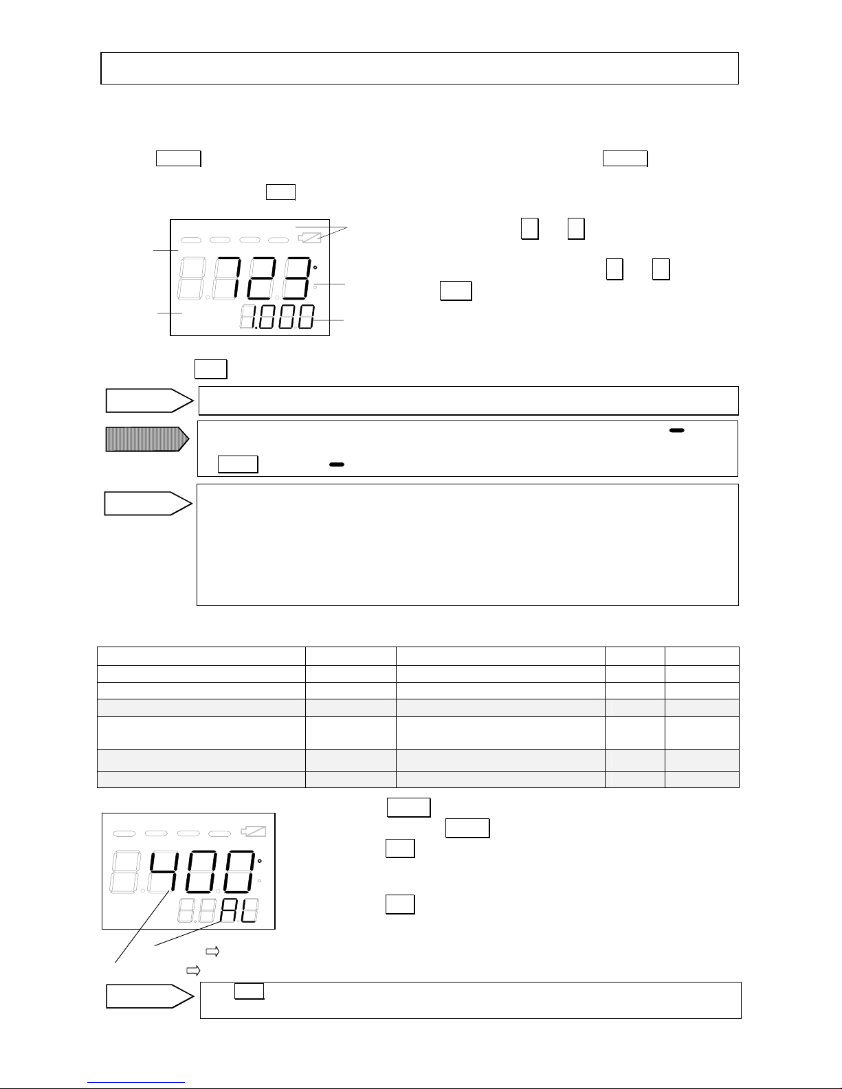
*1:Main display: Displays a measured value in the measurement mode or a setting value in the
setting mode.
*2:Sub display: Displays the data selected by SEL key in the me asurement mode or a mode in
the setting mode.
ε
VMXAAE
MEM
SEL
STD
MNI
NO
r
ALMEAS HOLD
ENT
CONT
MEAS
AH
F
C
3.3 External display
3.5 Functions of keys
Keys
Functions
Indications
(1) Measure Switch
Turns on the power supply and starts/stops a measurement. (The
power supply will be automatically turned off if any key is not
pressed for 15 seconds in the hold mode.)
MEAS
(2) Memory key
Changes from the standard or continuous measurement mode to the
data storage mode, or vice versa.
MEM
(3) Select key
Switches a data to be displayed in the sub display in the
measurement mode. Switches a mode in the sub display in the setting
SEL
(4) Up key Down key
Selects a mode or changes a setting value in the setting mode.
△ ▽
(5) Entry key
Stores the mode selected or the setting value entered in the setting
mode. Stores the measured value in the data storage mode.
ENT
3.6 Markers
Markers Major functions
Indications
Tb
Not used
"Tb"
CONT
The " " mark under "CONT" will light in the continuous measurement
mode.
"CONT"
MEM
The " " mark under the "MEM" will light in the data storage mode.
“MEM”
PEAK
When the PEAK is selected in the signal modulation mode selection,
the " " mark under the "PEAK" will light.
"PEAK"
(7)Main
marker
Will blink for low batteries.
MEAS
Will light in the measurement mode.
"MEAS"
HOLD
Will light in the hold mode.
"HOLD"
AL
Will light when the low alarm is activated.
"AL"
(8)Status
marker
AH
Will light when the high alarm is activated.
"AH"
o
C
Will light when a temperature is displayed in Celsius.
"
o
C "
(9)Unit
o
F
Will light when a temperature is displayed in Fahrenheit.
"
o
F "
MAX
Will light when the sub display shows a maximum temperature.
"MAX"
MIN
Will light when the sub display shows a minimum temperature.
"MIN"
AVE
Will light when the sub display shows an average temperature.
"AVE"
ε(εr)
Will light when the sub display shows an emissivity rate (ratio).
Single color type is the emissivity rate (ε) and 2-color type is the
emissivity ratio (εr).
"ε"or"εr"
(10)Sub
mareker
NO
Will light when the sub display shows a data storage number.
"NO"
3. Names and functions of component parts
3.4 Viewfinder
(9) Measurement unit
display
*1 Main displa
y
(1) Measure switch
Internal display
Targeting mark Targeting mark
center circle
*2 Sub display
(7) Main marker
(8) Status marker
(10)
Sub
marker
(2) (3) (4) (5) (6)
Page 8

INST No.INE-459-0P2CE Ver. 1.11
- 4 -
4.1 Loading batteries
• Remove the battery cover. Remove it by lightly pushing both sides of mark and sliding it to
the arrow direction.
4.2 Distance and diameter
The relation of measuring distance and measuring diameter is shown below.
4. Preparation for measurement
• Load two batteries with proper polarities.
Remove the battery cover by sliding it
upward while pushing both sides lightly.
SUM-3 SIZE
1
.
5V×2
• Battery life
The battery warning maker " " will blink when the battery life becomes
shortened. Replace the batteries (Alkaline AA or UM-3 batteries).
(Ref:[3.6 Markers])
When the marker goes off, replace the batteries (Alkaline AA or UM-3
batteries), too.
• Caution on removing the batteries
Make sure to remove the batteries from the [no-spring] side.
• Battery replacement
Make sure to load the batteries to the [spring] side first.
Replace 2 batteries together.
φ
90
φ
33
φ
20
φ
20
10m
5m
4m
0m
( At 90% energy limit )
Caution
Caution
Page 9

INST No.INE-459-0P2CE Ver. 1.11
- 5 -
4.3 Targeting
For the accurate temperature measurement, target at an object correctly
The following figures (1), (2), and (3) show the correct targeting based on the relation of the
measuring distance and the measuring diameter.
(1) For the measurement distance is shorter than 3m
Measurement diameter becomes “larger” than the targeting mark.
(2) For the measurement distance is about 3m
The measurement diameter and the inner side of the targeting mark are almost “same”.
(3) For the measurement distance is longer than 3m
Measurement diameter becomes “smaller” than the targeting mark.
4. Preparation for measurement
(1) For the measurement
distance is shorter than 3m
(2) For the measurement
distance is about 3m
(3) For the measurement
distance is longer than 3m
• The measuring diameter is fixed to ø20mm for the measuring distance up to 4m.
• For the measuring distance shorter than 3m, make sure to have the measuring
diameter larger than the targeting mark.
Remarks
Page 10

INST No.INE-459-0P2CE Ver. 1.11
- 6 -
(Common to [5.1 Standard measurement mode] and [5.2 Continuous measurement mode])
External display Main marker Internal display
Status marker
Main display
Sub marker Sub display
•Data in the sub display (Common to [5.1 Standard measurement mode] and [5.2 Continuous
measurement mode])
Sub marker Data displayed in sub displa
y
ε (εr) Emissivity rate (ε) for single color type, Emissivity ratio (εr) for 2-color type
MIN Minimum temperature during the MEAS key is being pressed
MAX Maximum temperature during the MEAS key is being pressed
AVE
Average temperature during the MEAS key is being pressed (Moving average of
25 points)
NO Stored data storage number. (Lights in the data storage mode only.)
5.1 Standard measurement mode
This mode is for measurement with holding the thermometer by hands.
• Sight through the viewfinder and match the center circle of the targeting circle to the center of
object measured.
• Press MEAS key for about 1 second to turn on the power supply and start a measurement.
The temperature measured will be displayed in the internal and external displays, and the status
marker “MEAS” will light in the external display.
(The measurement is continued during MEAS key is being pressed.)
• Select a data to be displayed in the sub display by pressing SEL key when you need.
By releasing MEAS key, the measurement will stop and the measured value will be held.
The status marker "MEAS" will go off and "HOLD" will light.
5.2 Continuous measurement mode
5.2.1 Start of continuous measurement
This mode is for continuous measurement by fixing the thermometer on a tripod or a universal head.
• Sight through the viewfinder and match the center circle of the targeting mark to the center of
object measured.
• For the continuous measurement mode, press MEAS key while pressing ▽ key.
When all segments of the external display (Ref. 3.3 [External display]) light, release MEAS key
quickly before a beep sounds. The " " mark under the main marker "CONT" and the status
marker "HOLD" will light.
・
5. Measuring *Make sure to press any keys until you hear an audible beep.
Tb CONT MEM PEAK
MEAS HOLD AL AH
C
F
MAX
AVE εr
MIN
TC
NO
• "oFL" will be displayed in the main and sub displays if the temperature data
measured is higher than the measuring range or "uFL" will be displayed if it is
lower than the measuring range.
[Temperature displaying "oFL"] 2-color: 2020°C (3668°F) Single color: 3020°C (5468°F)
[Temperature displaying "uFL"] 2-color: 580°C (1076°F) Single color: 380°C (716°F)
Remarks
• The internal display will go off in 10 seconds in the hold mode and the power
supply will be automatically turned off if any key is not pressed for 15 seconds in
the hold mode.
Remarks
• The status marker "MEAS" will light depending on its releasing timing of MEAS
key and the continuous measurement may start.
In this case, press MEAS key only again to light the status marker "HOLD" so that
the continuous measurement is temporally stopped.
Caution
Page 11

INST No.INE-459-0P2CE Ver. 1.11
- 7 -
ON
• Press MEAS key to start the continuous measurement. The status marker "HOLD" will go off
and the status marker "MEAS" will light.
• Select a data to be displayed in the sub display by pressing SEL key when you need.
• Press MEAS key again to hold the measured value. The status marker "HOLD" will light.
5.2.2 Cancellation of continuous measurement
• For canceling the continuous measurement mode, press MEAS key for about 1 second while
pressing △ key on the condition that the power supply is off. Confirm that the " " mark under
the main marker "CONT" has gone off.
5.3 Cautions on measurement
Warning
5. Measuring *Make sure to press any keys until you hear an audible beep.
• If any key is not pressed for 15 seconds in the hold mode, the power supply is
automatically turned off.
!
FILTER
Beam attenuation side
When you cancel the measurement, ensure that the continuous measurement is
stopped.
• "oFL" will be displayed in the main and sub displays if the temperature data
measured is higher than the measuring range or "uFL" will be displayed if it is
lower than the measuring range.
[Temperature displaying "oFL"] 2-color: 2020°C (3668°F) Single color: 3020°C (5468°F)
[Temperature displaying "uFL"]2-color: 580°C (1076°F) Single color: 380°C (716°F)
Remarks
When you use the thermometer in the continuous measurement mode, be careful
that the battery becomes consumed rapidly.
Caution
Remarks
Caution
• Light path
Be careful not to introduce water drops, dust particles, smoke, steam, or other
foreign substances into the light path between the object measured and the
objective lens of the thermometer.
• Interference causing high indication
Be careful not to apply the direct sunlight, light of an incandescent lamp, flame or
other thermal radiation to the object measured and the objective lens of the
thermometer.
Caution
• Never directly sight the objective lens of the thermometer to the sunlight for
protecting your eyes and a sensing element.
Warning
• For the measurement of object exceeding 1500oC (2732°F), make sure to set the
beam attenuation filter selector knob to "ON" (beam attenuation side) for
protecting your eyes. (Refer to the above figure.)
• However, when you feel glare on the measurement of objects lower than 1500
o
C
(2732°F), set the beam attenuation filter selector knob to "ON" (beam attenuation
side). (Refer to the above figure.)
Warning
Page 12
INST No.INE-459-0P2CE Ver. 1.11
- 8 -
5.4 Emissivity rate setting
This is for the setting of a correct emissivity rate of an object measured. Principally, when you measure the
object with the single color type, set the emissivity rate if you have already known its value.
• Press MEAS key for about 1 second to turn on the power supply and then release MEAS key.
The status marker "HOLD" will light.
• In the hold mode, press SEL key several times to enter the emissivity rate setting mode "ε" ("εr " for
2-color type) in the sub marker. (Ref: [3.6 Markers]).
• By pressing either △ or ▽ key, the least significant
digit of 4-digit numerical figure will blink to set it.
• Set the desired figure by pressing △ or ▽ key.
• Press ENT key. The blinking will stop and the blinking
digit will shift to the next higher digit.
• Repeat the above procedure up to the most significant digit for setting the emissivity rate (4 digits).
• By pressing ENT key at the most significant digit, the setting of emissivity rate will be completed.
5.5 Measurement mode selections (This paragraph explains the items highlighted.)
Measurement modes are shown in the list below. By referring to the list, select the desired modes.
Settings/Mode selections Sub display Setting range Initial Paragraph
Low temperature alarm setting AL oFF, 400 to 3000ºC/752 to 5432ºF oFF 5.6.1
High temperature alarm setting AH oFF, 400 to 3000ºC/752 to 5432ºF oFF 5.6.2
Signal modulation mode selection modu dELy, PEAk dELy 5.5.1
Modulation value setting
tAu
dEc
0.0, 0.2, 0.5, 1.0 (second)
0, 2, 5, 10ºC
(ºF)
/second
0.0s
0ºC/s
5.6.3
Measuring unit selection Unit C (ºC), F (ºF) C (ºC) 5.5.2
2-color/single color selection CoLr 2, 1 2 5.5.3
• Press MEAS key for about 1 second to turn on the power supply
and then release MEAS key. The status marker "HOLD" will light.
• Press SEL key for about 2 seconds in the hold mode to move to the
setting mode. A setting value will be displayed in the main display
and its mode will be displayed in the sub display.
• Press SEL key for selecting a mode. (Ref: [8.4 System settings]
• For the selecting procedure of the above modes, refer from [5.6.1
Low temperature time constant setting] to [5.6.3 Modulation value
setting].
5. Measuring *Make sure to press any keys until you hear an audible beep.
Tb CONT MEM PEAK
MEAS HOLD AL AH
C
F
MAX
AVE εr
MIN
TC
NO
Status
marker
Sub
marker
Main
marker
Sub
display
Main
dis
play
• The setting range is 0.100 to 1.900. (0.001 increment) The initial is "1.000".
Remarks
• The emissivity rate setting is disabled in the data storage mode (when the " " mark
under the main marker "MEM" lights). For canceling the data storage mode, press
MEM key. The " " mark under the main marker "MEM" will go off.
Caution
• When an emissivity rate is unknown, adjust the emissivity rate to get the same
temperature value as the value measured by a thermocouple.
[Example]
Measured value by the thermometer > Measured value by a thermocouple
⇒ Increase the emissivity rate
Measured value by the thermometer < Measured value by a thermocouple
⇒ Decrease the emissivity rate
Reference
• If SEL key is pressed for 2 seconds in the setting mode or if any key is not pressed for
1 minute, the thermometer will return to the measurement mode.
Remarks
Sub display Display of [its item]
« Setting mode screen »
Main display Display of [parameter]
Tb CONT MEM PEAK
MEAS HOLD AL AH
C
F
MAX
AVE εr
MIN
NO
Page 13

INST No.INE-459-0P2CE Ver. 1.11
- 9 -
5.5.1 Signal modulation mode selection
Maximum value and average value can be extracted continuously from the measurement signal
(real signal).
• Press MEAS key for about 1 second to turn on the power supply and then release MEAS key.
The status marker "HOLD" will light.
• Press SEL key for about 2 seconds in the hold mode to move to the setting mode. A setting value
will be displayed in the main display and its mode will be displayed in the sub display.
• Press SEL key to display "modu" in the sub display.
• By pressing △ or ▽ key, either "dELy" (average value) or "PEAk" (maximum value) will
blink in the main display.
• Select either one and press ENT key to store it.
• By storing the dELy, the "dELy" will stop blinking
and light in the main display.
• By storing the PEAk, the "PEAk" will stop
blinking and light in the main display. The " "
mark will light under the main marker "PEAK".
dELy
The temperature displayed is based on the first-order lag signal selected in [5.6.3-1
Modulation time constant setting].
PEAk
When the temperature measured increases, its displayed value is based on the real
signal. When the temperature measured decreases, its displayed value is based on the
value selected in [5.6.3-2 Damping degree setting].
5.5.2 Temperature unit selection
Select ºC or ºF for measuring temperature unit.
• Press MEAS key for about 1 second to turn on the power supply and then release MEAS key.
The status marker "HOLD" will light.
• Press SEL key for about 2 seconds in the hold mode
to move to the setting mode. A setting value will be
displayed in the main display and its mode will be
displayed in the sub display.
• Press SEL key to display "unit" in the sub display.
• By pressing △ or ▽ key, either "C" (ºC)
or "F" (ºF) will blink in the main display.
• Select either one and press ENT key to store it.
The “C” or “F” selected will stop blinking and light
in the main display. [When the “C” is selected, “ºC”
will light in the unit display. When the “F” is
selected, “ºF” will light in the unit display.
5. Measuring *Make sure to press any keys until you hear an audible beep.
・The initial setting is "dELy".
Tb CONT MEM PEAK
MEAS HOLD AL AH
C
F
MAX
AVE ε
r
MIN TC NO
Main display
Sub display
Unit display
• If SEL key is pressed for 2 seconds in the setting mode or if any key is not
pressed for 1 minute, the thermometer will return to the measurement mode.
Main display
Sub display
Tb CONT MEM PEAK
MEAS HOLD AL AH
C
F
MAX
AVE
r
MIN TC NO
Remarks
Remarks
• The initial setting is "C" (ºC).
• The initial unit display is ºC.
Remarks
• If SEL key is pressed for 2 seconds in the setting mode or if any key is not
pressed for 1 minute, the thermometer will return to the measurement mode.
Remarks
Page 14

INST No.INE-459-0P2CE Ver. 1.11
- 10 -
5.5.3 2-color type/single color type selection
Select a measurement mode by 2-color type or single color type in the VF-3000.
• Press MEAS key for about 1 second to turn on the power supply and then release MEAS key. The status
marker "HOLD" will light. Then press SEL key for about 2 seconds in the hold mode to move to the setting
mode. A setting value will be displayed in the main display and its mode will be displayed in the sub display.
• Press SEL key to display "CoLr" in the sub display.
• By pressing △ or ▽ key, either "2" (2-color type) or
"1" (single color type) will blink in the main display.
• Select either one and press ENT key to store it. The “2”
(2-color type) or “1” (single color type) selected will stop
blinking and light in the main display.
5.6 Measurement mode settings (This paragraph explains the items highlighted.)
Measurement modes are shown in the list below. By referring to the list, set the desired modes.
Settings/Mode selections Sub display Setting range Initial Paragraph
Low temperature alarm setting AL oFF, 400 to 3000ºC/752 to 5432ºF oFF 5.6.1
High temperature alarm setting AH oFF, 400 to 3000ºC/752 to 5432ºF oFF 5.6.2
Signal modulation mode selection modu dELy, PEAk dELy 5.5.1
Modulation value setting * tAu
dEc
0.0, 0.2, 0.5, 1.0 (second)
0, 2, 5, 10ºC (ºF)/second
0.0s
0ºC/s
5.6.3
All stored data erasing AdEL no, yES no 6.5
Measuring unit selection Unit C (ºC), F (ºF) C 5.5.2
2-color/single color selection CoLr 2, 1 2 5.5.3
* The mode for the modulation value setting differs by the selection of the signal modulation mode.
(Ref: [5.5.1 Signal modulation mode selection])
5.6.1 Low temperature alarm setting
This setting is for a judgment of low alarm during measurement. When the low alarm is judged, the status
marker "AL" will light and the buzzer will sound. When the "oFF" is selected, neither the alarm judgment can
be executed nor the buzzer can be sound.
• Press MEAS key for about 1 second to turn on the power supply and then release MEAS key. The status
marker "HOLD" will light. Then press SEL key for about 2 seconds in the hold mode to move to the setting
mode. A setting value will be displayed in the main display and its mode will be displayed in the sub display.
• Press SEL key to display "AL" in the sub display. By pressing △ key, the least significant digit will blink
to set it.
• Set the desired figure by △ or ▽ key and press ENT
key for shifting the setting digit to the next higher digit.
• Repeat the above procedure up to the most significant
digit.
• By pressing ENT key at the most significant digit, the
setting value will be stored.
5. Measuring *Make sure to press any keys until you hear an audible beep.
Tb CONT MEM PEAK
MEAS HOLD AL AH
C
F
MAX
AVE ε
r
MIN TC NO
Main display
Sub display
• The initial setting is "2" (2-color type).
Remarks
• If SEL key is pressed for 2 seconds in the setting mode or if any key is not pressed for
1 minute, the thermometer will return to the measurement mode.
Remarks
• If SEL key is pressed for 2 seconds in the setting mode or if any key is not pressed for
1 minute, the thermometer will return to the measurement mode.
Remarks
[How to reset the low temperature alarm to " oFF"]
• Press SEL key for about 2 seconds to display "AL" on the sub display. By changing the
displayed numeric figure to be lower than 399ºC (751ºF) by △ ,▽ and ENT keys,
"oFF" will be displayed.
• Press ENT key to store it.
Reference
• The setting range is “oFF” or 400 to 3000ºC/752 to 5432ºF. The initial is "oFF".
Reference
Main display
Sub displa
y
Tb CONT MEM PEAK
MEAS HOLD AL AH
C
F
MAX
AVE εr
MIN
NO
Page 15

INST No.INE-459-0P2CE Ver. 1.11
- 11 -
5.6.2 High temperature alarm setting
This setting is for a judgment of high alarm during measurement. When the high alarm is judged, the
status marker "AL" will light and the buzzer will sound. When the "oFF" is selected, neither the alarm
judgment can be executed nor the buzzer can be sound.
• Press MEAS key for about 1 second to turn on the power supply and then release MEAS key. The
status marker "HOLD" will light. Then press SEL key for about 2 seconds in the hold mode to move to
the setting mode. A setting value will be displayed in the main display and its mode will be displayed in
the sub display. Press SEL key to display "AH" in the sub display. By pressing △ key, the least
significant digit will blink to set it.
• Set the desired figure by △ or ▽ key and press
ENT key for shifting the setting digit to the next higher
digit.
• Repeat the above procedure up to the most significant
digit.
• By pressing ENT key at the most significant digit, the
setting value will be stored.
5.6.3 Modulation value setting
When the "dELy" is selected in the signal modulation mode, the first-order lag degree can be adjusted by
setting of the modulation time constant.
When the "PEAk" is selected, the damping degree of signal after tracing the peak value can be adjusted.
• Press MEAS key for about 1 second to turn on the power supply and then release MEAS key. The
status marker "HOLD" will light. Then press SEL key for about 2 seconds in the hold mode to move to
the setting mode. A setting value will be displayed in the main display and its mode will be displayed in
the sub display.
5.6.3-1) Modulation time constant selection (effective when the "dLEy" is selected in the signal
modulation mode)
• Press SEL key to display "tAu" in the sub display.
• By pressing △ or ▽ key, the modulation time
constant will blink in order of 0.0 → 0.2 → 0.5 → 1.0
(second) in the main display. Select the desired
modulation time constant and press ENT key.
5.7.3-2) Damping degree selection (effective when the "PEAk" is selected in the signal modulation
mode)
• Press SEL key to display "dEc" in the sub display.
• By pressing △ or ▽ key, the modulation time constant
will blink in order of 0 → 2 → 5 → 10 (ºC/second)
(ºF/second) in the main display. Select the desired damping
degree and press ENT key.
5. Measuring *Make sure to press any keys until you hear an audible beep.
Tb CONT MEM PEAK
MEAS HOLD AL AH
C
F
MAX
AVE ε
r
MIN TC NO
Main display
Sub display
Main display
Tb CONT MEM PEAK
MEAS HOLD AL AH
C
F
MAX
AVE
r
MIN TC NO
Sub display
Main display
Sub display
Tb CONT MEM PEAK
MEAS HOLD AL AH
C
F
MAX
AVE
r
MIN TC NO
• The setting range is “oFF” or 400 to 3000ºC/752 to 5432ºF. The initial is "oFF".
Reference
[How to reset the low temperature alarm to " oFF"]
• Press SEL key for about 2 seconds to display "AH" on the sub display. By changing the
displayed numeric figure to be lower than 399ºC (751ºF) by △ , ▽ and ENT keys,
"oFF" will be displayed. Press ENT key to store it.
Reference
• If SEL key is pressed for 2 seconds in the setting mode or if any key is not pressed for
1 minute, the thermometer will return to the measurement mode.
Remarks
• The initial is "0.0" second. (The displayed value is based on th
e
real signal without any
modulation.)
Remarks
• If SEL key is pressed for 2 seconds i
n
the setting mode or if any key is not pressed for
1 minute, the thermometer will return to the measurement mode.
Remarks
• The initial is "0.0" second. (The displayed value is based on the real signal without any
modulation.)
Remarks
• If SEL key is pressed for 2 seconds in the setting mode or if any key is not pressed for
1 minute, the thermometer will return to the measurement mode.
Remarks
Page 16

INST No.INE-459-0P2CE Ver. 1.11
- 12 -
Sub
marker
Sub
marker
The thermometer provides a function of storing measured data (temperature measured by the
thermometer and the emissivity rate). The data storage number is from 1 to 100. When ENT key is
pressed, the measured data is stored.
6.1 Data storage mode
• Press MEM key in the hold mode in the standard measurement mode or continuous measurement
mode (Ref: [5.1 Standard measurement mode], [5.2 Continuous measurement mode]) to move to
the data storage mode. The " " mark under the main marker "MEM" will light and "NO" will
be displayed in the sub marker. Also, the data storage number "1" will be displayed in the sub
display for the initial data storage. When measured data have been already stored in any data
storage number, the "next number" to the last data storage number will be displayed.
• Press MEAS key for about 1 second to measure. The measurement is depended on the
measurement mode (Ref: [5.1 Standard measurement mode], [5.2 Continuous measurement
mode]).
6. Temperature data storage. *Make sure to press any keys until you hear an audible beep.
Tb CONT MEM PEAK
MEAS HOLD AL AH
C
F
MAX
AVE ε
r
MIN TC NO
Tb CONT MEM PEAK
MEAS HOLD AL AH
C
F
MAX
AVE ε
r
MIN TC NO
Main
marker
Main
display
Sub
dis
play
Tb CONT MEM PEAK
MEAS HOLD AL AH
C
F
MAX
AVE ε
r
MIN TC NO
(Initial data storage)
Tb CONT MEM PEAK
MEAS HOLD AL AH
C
F
MAX
AVE ε
r
MIN TC NO
Main
marker
Main
display
Sub
dis
play
(In case of data stored up to No. 99 last time)
• In case that the measured data have been stored in the data storage mode last
time, the next number to the last data storage number will be displayed in the sub
display. (For the above example, the number "100" will be displayed when the
measured data have been stored up to the number 99.)
Reference
● Data storage in the standard measurement mode: In the measurement by keeping
MEAS key pressed (with the status marker "MEAS" lit) or in the temporary
measurement stop (with the status marker "HOLD" lit), by pressing ENT key,
the measured data (the measured temperature and the setting emissivity rate) will
be stored. The sub display will display "Str" instantly
when the measured data is
stored, and then will display the next data storage number.
● Data storage in the continuous measurement mode
: In the measurement by
keeping MEAS key pressed (on the condition that the " " mark under the
main marker "CONT" and the status marker "MEAS" light together), by
pressing ENT key, the measured data (the measured temperature and the setting
emissivity rate) will be stored. The sub display will display "Str" instantly when
the measured data is stored, and then will display the next data storage number.
Reference
Page 17

INST No.INE-459-0P2CE Ver. 1.11
- 13 -
6. Temperature data storage. *Make sure to press any keys until you hear an audible beep.
• To return to the standard measurement mode or the continuous measurement
mode from the data storage mode,
To standard measurement mode: Release MEAS key to move to the hold mode
To continuous measurement mode: Press MEAS key again to move to the hold
mode.
In the hold mode, press MEM key.
When the " " mark under the main marker "MEM" goes off, the mode
returns to the standard measurement mode or the continuous measurement mode.
Remarks
• On this condition, by pressing SEL key, "
ε
" will be displayed in the sub marker
and the emissivity rate will be displayed in the sub display.
• The emissivity rate displayed is the emissivity rate set in [5.4 Emissivity rate
setting] or 1.000 (initial) if not set.
• The measured data stored in the specific data storage number can be recalled by
[(2) Specific data storage number setting]. (Ref. [6.2.2 Recalling of stored data])
Remarks
• For changing the emissivity rate at the above ,
For the standard measurement mode, release MEAS key to move to the hold
mode
For the continuous measurement mode, press MEAS key again to move to the
hold mode.
Referring to [5.4 Emissivity rate setting], set a new emissivity rate by pressing
△ , ▽ and ENT keys in the hold mode.
• The new emissivity rate set will be effective from the next data storage number.
When you change the emissivity rate at the specific data storage number, follow
this procedure.
Reference1
Remarks
(1) Initial data storage number: The initial data storage number starts from "1".
(2) Specific data storage number setting: The specific data storage number for the
next data storage can be set by pressing △ , ▽ and ENT keys in the hold
mode. (Ref: [6.2.1 Data storage number setting])
Reference
• On the condition that the measured data stored in the specific data storage
number is being displayed in the main display, if you press MEAS key to
measure and then press ENT key, be careful that the measured data already
stored will be overwritten by a new measured data.
• If you do not want to overwrite, follow the procedures shown in [6.2.1 Data
storage number setting].
Caution
• Measured data can be stored in the data storage number from No. 1 to No. 100,
but when a measured data is stored in the data storage No. 100, the memory
becomes in the memory full condition and new measured data can not be stored
even if ENT key is pressed after then. (Ref: [6.3 Memory full])
Caution
Reference1
Page 18

INST No.INE-459-0P2CE Ver. 1.11
- 14 -
6.2 Data storage number setting and recalling of stored data
6.2.1 Data storage number setting
For setting a data storage number for the next data storage, take the following procedure.
• Press MEM key in the “hold” mode in the standard measurement mode or continuous
measurement mode to move to the data storage mode. The " " mark under the main marker
"MEM" will light and "NO" will be displayed in the sub marker. Also, the data storage number
"1" will be displayed in the sub display for the initial data storage. When measured data have been
already stored in any data storage number, the "next number" to the last data storage number will
be displayed.
• By pressing △ or ▽ key in the hold mode, the
least significant digit will blink for setting it.
• Set the desired figure by △ or ▽ key and press
ENT key for shifting the setting digit to the next
higher digit.
• Repeat the above procedure up to the most
significant digit.
• By pressing ENT key at the most significant digit,
the setting of data storage number will be
completed.
6. Temperature data storage. *Make sure to press any keys until you hear an audible beep.
Tb CONT MEM PEAK
MEAS HOLD AL AH
C
F
MAX
AVE ε
r
MIN TC NO
Main
marker
Main
display
Sub
display
Sub
marker
• When any measured data has not been stored in the setting data storage number,
"non" will be displayed in the main display.
Reference
• When a measured data has been stored in the setting data storage number, its
temperature data will be displayed in the main display.
Reference
• On condition that a data storage number has been set by the above procedure,
when you press MEAS key to start a measurement and then press ENT key, the
measured data already stored in its data storage number will be overwritten by a
new measured data.
• If you do not want to overwrite the measured data already stored in its data
storage number, follow the above procedure again to select the data storage
number that any measured data has not been stored in.
Caution
Page 19

INST No.INE-459-0P2CE Ver. 1.11
- 15 -
6.2.2 Recalling of stored data
For setting a data storage number for the next data storage, take the following procedure.
• Press MEM key in the hold mode in the standard measurement mode or continuous measurement
mode to move to the data storage mode. The " " mark under the main marker "MEM" will light
and "NO" will be displayed in the sub marker. Also, the data storage number "1" will be
displayed in the sub display for the initial data storage. When measured data have been already
stored in any data storage number, the "next number" to the last data storage number will be
displayed.
• By pressing △ or ▽ key in the hold mode, the least
significant digit will blink for setting it.
• Set the desired figure by △ or ▽ key and press ENT
key for shifting the setting digit to the next higher digit.
• Repeat the above procedure up to the most significant digit.
• By pressing ENT key at the most significant digit, the
setting of data storage number to recall will be completed.
6. Temperature data storage. *Make sure to press any keys until you hear an audible beep.
Main
marker
Main
display
Tb CONT MEM PEAK
MEAS HOLD AL AH
C
F
MAX
AVE ε
r
MIN TC NO
Sub
display
Sub
marker
• For canceling the display of the data stored, press MEAS key to disappear the
" " mark under the main marker "MEM".
• For starting the measurement again, refer to [5.1 Standard measurement mode]
and [5.2 Continuous measurement mode].
Reference
When you recall a stored data, be careful on the following point.
(Example)
1) If the measured data have been stored in the data storage number up to No. 50,
"51", that is the next number to the last data storage number, will be displayed
in the sub display.
2) At this time, if you want to display the measured data stored in the data storage
No. 48, recall the number "48" by △ , ▽ and ENT keys following the
above procedure, to display the measured data stored.
3) On this condition, if MEAS key is pressed again to measure, new measured
data will be stored from the data storage No. 48 and the next data storage No.
becomes “49”. It means the measured data already stored from No.48 will be
overwritten by new measured data.
If you do not want to overwrite the measured data already stored, reset the data
storage number to be the next number that a new measured data is to be stored
originally. (Refer to [6.2.1 Data storage number setting] for resetting.)
Caution
• The temperature data stored in the data storage number recalled will be displayed
in the main display.
Reference
• On this condition, press SEL key to display "
ε
" in the sub marker. The emissivity
rate, which has been stored together with the temperature data in the main display,
will be displayed in the sub display.
Remarks
• When any measured data has not been stored in the data storage number recalled,
"non" will be displayed in the main display.
Reference
48
49
50
51
47
Data storage number
set this ti me
Original next data
storag e num b er
Data storage numbers that measured
data have already been s t ored in
Data storage number that a new
measur ed d ata is stored in
Page 20

INST No.INE-459-0P2CE Ver. 1.11
- 16 -
6.3 Memory full
The data storage number is up to No. 100. When a measured data is stored in the data storage No.
100, the memory becomes full and new measured data can not be stored after that.
6.4 Erasing all stored data
When all data being stored are not necessary or the memory becomes fill (Ref: [6.3 Memory full],
take the following procedure to erase all stored data.
• Press MEM key in the hold mode on the standard or continuous measurement mode to move to
the data storage mode. The " " mark under the main marker "MEM" will light. (The " "
mark will blink on the memory full condition.
• By pressing SEL key for about 2 seconds in the hold mode, a parameter will be displayed in the
main display and its item will be displayed in the sub display.
• Press SEL key to display "AdEL" in the sub display.
• At the first time, "no" (deletion disable) will be
displayed in the main display.
• By pressing △ or ▽
key, either "no" (deletion
disable) or "yES" (deletion enable) will blink in the
main display.
• For the deletion of all data stored, select "yES"
(deletion enable) and then press ENT key. "dEL"
will be displayed instantly and then "no" will light in
the main display.
If no data have been stored, "non" will be displayed
instantly and then "no" will light in the main display.
• If you do not want to delete all data stored, select
"no" (deletion disable) and then press ENT key.
The blinking of "no" will stop and "no" will light.
• To quit this mode, press SEL key for about 2 seconds.
6. Temperature data storage. *Make sure to press any keys until you hear an audible beep.
Tb CONT MEM PEAK
MEAS HOLD AL AH
C
F
MAX
AVE ε
r
MIN TC NO
Main display
Sub display
Tb CONT MEM PEAK
MEAS HOLD AL AH
C
F
MAX
AVE ε
r
MIN TC NO
Main display
Sub display
• On the memory full condition, the " " mark under the main marker "MEM"
will blink.
• In the measurement mode or the hold mode, by pressing ENT key, the measured
data (thermometer temperature and emissivity rate) will be stored.
• The sub display will display "Str" instantly when the measured data is stored and,
when the measured data is stored on the data storage No. 100, the memory
becomes full.
• The sub display will display No. 100 and the main marker "HOLD" will light
continuously.
Further the " " mark under the main marker "MEM" will blink continuously.
After that, any measured data can not be stored.
On this condition, if ENT key is pressed for storing a new measured data, the sub
display will display "FULL" instantly and then display No. 100.
Remarks
• For storing a new measured data on the above condition,
1) Store the new measured data in the data storage number, that have not stored
any measured data, by referring to [6.2.1 Data storage number setting], or
2) Store the new measured data in the data storage number, that can be
overwritten, by referring to [6.2.1 Data storage number setting], or
3) Store the new measured data by erasing the measured data stored, by referring
to [6.4 Erasing all stored data].
Reference
• The initial is "no" (deletion disable).
Remarks
Page 21

INST No.INE-459-0P2CE Ver. 1.11
- 17 -
7.1 Self-diagnostic function
The thermometer provides the self-diagnostic function.
The followings are the displays on abnormal conditions.
Display
(Main
display)
Contents Alarm Countermeasure
High limit over range
(The object temperature
exceeds the measuring
range of the thermometer)
The status marker
"AH" lights and the
buzzer sounds. *1
Is the emissivity rate set too low?
Set the correct emissivity rate by
referring to [5.4 Emissivity rate
setting].
Low limit over range
(The object temperature is
lower than the measuring
range of the thermometer.)
The status marker
"AL" lights and the
buzzer sounds. *1
Is the emissivity rate set too high?
Set the correct emissivity rate by
referring to [5.4 Emissivity rate setting].
Abnormal ambient
temperature
(The thermometer is placed
in the environment other
than the working
temperature.)
Er1 display only
Use the thermometer in the
environment from 0 to 50ºC (32
to 122oF).
Main display (Thermometer)
*2
EEPROM data broken
(Stored data, temperature
data and calibration data
have been initialized by the
data ROM broken.)
Er4 display only
Re-adjustment is necessary.
Return the thermometer to us.
(Stored data and calibration data
are initialized.)
*1 When the alarm set-point is "oFF", no buzzer sounds.
*2 When the power supply is turned on or when the stored data is displayed, this error code is
displayed.
7.2 Storage
7.3 Cleaning of objective lens
Wipe the objective lens periodically with a soft cloth.
7.4 Cleaning of external display and eyepiece cover
Clean them periodically with a soft cloth.
7. Maintenance and check
• Don’t store the thermometer at a hot and/or wet place.
• Make sure to mount the lens cap for storage.
• Remove the batteries if the thermometer is not used for longer than 2 weeks,
otherwise the thermometer may become defective due to an electrolyte leak
failure of the batteries.
Caution
Page 22

INST No.INE-459-0P2CE Ver. 1.11
- 18 -
8.1 Modes at start up
The following operation modes are available by the key combinations at the start up.
Keys Modes Remarks
Press MEAS key only
(about 1 second)
Standard measurement or
continuous measurement
Measurement with the same measurement
mode as the last starting up
Press MEAS while
pressing △ key
Standard measurement
Press MEAS key
while pressing ▽ key
Continuous measurement The " " mark will light under the main
marker "CONT".
8.2 Table of screens
The screens displayed in the external display are the following 3 kinds basically.
Screen Outline
Measurement
screen
Measurement by MEAS key
In the hold mode in the standard or continuous measurement mode, the setting and
automatic calculation of emissivity rate is possible.
Data storage
screen
Data storage number, stored data display and storing measured data into memory are
possible. By pressing MEM key in the standard or continuous measurement mode,
the mode will become the data storage mode and the " " mark will light under
the main marker "MEM".For returning to the standard or continuous measurement
mode, press MEM key again.
Measurement
mode settings
screen
Display and setting of measurement mode. By pressing SEL key for about 2
seconds in the standard measurement mode or continuous measurement mode, the
mode will become the measurement mode settings mode.
In the measurement mode settings mode, by pressing SEL key for about 2 seconds
or any key is not pressed for 1 minute, the mode will return to the measurement
mode or the data storage mode.
8.3 Measurement mode settings/display
8.3.1 Emissivity rate setting/display
Parameter item Display Parameter Initial Paragraph
Emissivity rate (ratio)
ε (εr) 1.900 to 0.100 1.000
5.4
* The emissivity rate can not be set in the data storage mode.
8.3.2 Data storage number setting/display
Parameter item Display Parameter Initial Paragraph
Data storage number
NO 1 to 100 1
6.2
* The data storage number is only displayed in the data storage mode.
8.4 System settings
Settings Display Parameter Initial Paragraph
Low temperature alarm setting AL
oFF, 400 to 3000ºC/752 to 5432ºF
oFF 5.6.1
High temperature alarm setting AH
oFF, 400 to 3000ºC/752 to 5432ºF
oFF 5.6.2
Signal modulation mode selection
modu dELy, PEAk dELy 5.5.1
Modulation value setting *
tAu
dEc
0.0, 0.2, 0.5, 1.0 (second)
0, 2, 5, 10ºC (ºF)/second
0.0s
0ºC/s
5.6.3
All stored data erasing AdEL no, yES no 6.4
Measuring unit selection
Unit C(ºC), F(ºF) C(ºC) 5.5.2
2-color/single color wide
selection
CoLr 2, 1 2 5.5.3
* The mode for the modulation value setting differs by the selection of the signal modulation mode.
(Ref: [5.5.1 Signal modulation mode selection])
8. List of Starting Up Modes
Page 23

INST No.INE-459-0P2CE Ver. 1.11
- 19 -
50
50
75
23
100
45
137
11
66
4
9.1 Specifications
Model VF-3000
Measuring System
Narrow band radiation thermometer
Detecting Element Si/InGaAs
Measuring Wavelength 0.9/1.55µm
Measuring Range
2-color type
Single color type
:600 to 2000°C (1112 to 3632ºF)
:400 to 3000°C (752 to 3632ºF)
Accuracy Ratings *
Lower than 1000°C(1832ºF)
1000°C to 1500°C(1832 to 2732ºF)
1500°C to 2000°C(2732 to 3632ºF)
Higher than 2000°C(3632ºF)
:±6°C(11ºF)
:±0.6% of reading
:±1.2% of reading
:±2.4% of reading
Repeatability ±1°C
Temperature drift
Lower than 1000°C(1832ºF)
Higher than 1000°C(1832ºF)
: 0.2°C/°C(0.2ºF/ºF)
: 0.02%/°C(0.01%/ ºF)of reading
Stability
In the test environment
required by EMC d ir ec tiv es
±15°C(±27ºF)
Resolution 1°C(2ºF)
Response Time 0.2 second
Emissivity Compensation 1.900 to 0.100
Mathematics Maximum value, minimum value, average value
Signal Modulation Peak, delay
Display System
LCD digital 4 digits, Displayed in the viewfinder and in external
display
Data Memory Function Maximum 100 data
Optical System Fixed focus type
Distance/diameter ø20/4000mm (Ref. [4.2 Distance and diameter])
Targeting Direct viewing finder
Lens Diameter ø20mm
Other Functions
Auto-power-off, Automatic back-lit display, Continuous
measurement,
°C/°F selection, Battery check, High / low alarms
Ambient Temperature 0 to 50°C(32 to 122ºF)
Power Supply
2 AA (UM-3) alkaline batteries (about 30 hours for continuous
measurement)
Casing Material ABS resin
Wei ght About 350g (thermometer only)
Attachment 2 pieces of AA (UM-3) battery
* At ε =1.0. reference operating conditions: 23°C ± 5°C (73ºF±9ºF), relative humidity: 35 to 75%RH
9.2 Outside dimensions
9. General Specifications
Unit: mm
Page 24

INE-459-0P2CE Oct-08 Thermo-hunter Model: VF-3000 Printed in Japan Ver.1.11 ‘03‐04First
OPTEX CO.LTD
5-8-12 Ogoto Otsu 520 Japan
TEL (077)579-8680 FAX (077)579-8199
http://www.optex.co.jp/meas/
meas@optex.co.jp
 Loading...