


No.59-1881-3
UL No.59-1881-3 131115
INSTALLATIONINSTRUCTIONS
PHOTOELECTRIC DETECTOR |
Advanced |
Standard |
Detection range |
™ |
|
|
|
SmartLine series |
SL-200QDM |
SL-200QDP |
60m/200ft. |
|
|||
|
SL-350QDM SL-350QDP |
100m/350ft. |
|
|
SL-650QDM |
SL-650QDP |
200m/650ft. |
A photoelectric detector consists of an infrared light source that generates IR(Infrared) beams, and an IR receiver that detects the IR beams. The transmitter and receiver are installed on opposite sides of the area to be monitored. The receiver detects when the IR beams are physically interrupted by an intruder, and sends an alarm signal to be a control panel.
Transmitter |
Receiver |
FEATURES
•Quad high power beams
•Double modulated beam
•Smart design
-Slim body design
-Easy-to-see vivid interior color for optical alignment
-IP65*1 waterproof structure
•4 channel beam frequency selector
•Alignment level indicator
•Viewfinder with 2X magnification
•Various options (refer to page 20)
( HU-3*1, ABC-4*1, BC-4*1, CBR-4, PSC-4*1, BAU-4*1 )
•UL/c-UL Listed
*1 not evaluated by UL
*2 not require any additional tool
•Beam interruption adjustment function
•D.Q. circuit (environmental disqualification)
•Tamper function
•Beam power control selector
•Alarm memory
•Sound assist function
-Optical alignment
-Beam reception status
-Walk test
[ SL-QDM only ]
•Auto Transmit Power Control (A.T.P.C*2) to optimize the beam power
•Integrated Alignment Status Communication (I.A.S.C*2) to communicate the transmitter and receiver
•Re-transmitting circuit function
•Solar Battery Unit SBU-4*1 (option)
CONTENTS
1 INTRODUCTION |
|
|
3-3 FUNCTION.................................................... |
11 |
1-1 BEFORE YOUR OPERATION ....................... |
2 |
4 |
OPTICAL ALIGNMENT |
|
1-2 PRECAUTIONS....................................................... |
2 |
|
4-1 OPTICAL ALIGNMENT FOR UPPER AND |
|
1-3 PARTS IDENTIFICATION..................................... |
3 |
|
LOWER BEAM.............................................. |
15 |
2 INSTALLATION |
|
|
4-2 OPERATION CHECK.................................... |
17 |
2-1 SEPARATING................................................. |
4 |
5 |
TROUBLESHOOTING |
|
2-2 WIRING.......................................................... |
4 |
|
5-1 TROUBLESHOOTING .................................. |
17 |
2-3 TERMINAL ..................................................... |
5 |
6 |
OPTIONAL SETTING |
|
2-4 WIRING DIAGRAM ........................................ |
5 |
|
6-1 HEATER UNIT HU-3 (OPTION) .................... |
18 |
2-5 WIRING DISTANCE BETWEEN POWER |
|
|
6-2 SOLAR BATTERY UNIT SBU-4 (OPTION)... |
18 |
SUPPLY AND DETECTOR ............................ |
6 |
7 |
DIMENSIONS |
|
2-6 WALL MOUNTING ......................................... |
6 |
|
7-1 DIMENSIONS ............................................... |
19 |
2-7 POLE MOUNTING ......................................... |
8 |
8 |
SPECIFICATIONS |
|
2-8 MOUNTING IN THE BEAM TOWER.............. |
9 |
|
8-1 SPECIFICATIONS......................................... |
19 |
2-9 INSTALLATION EXAMPLE AT PARTICULAR CASE... |
9 |
9 |
OPTIONS |
|
3 FUNCTION SETTING |
|
|
9-1 OPTIONS ...................................................... |
20 |
3-1 DIP SWITCH ................................................. |
10 |
|
|
|
3-2 BEAM POWER CONTROL SELECTOR....... |
10 |
|
|
|
-1-
1 INTRODUCTION
1-1 BEFORE YOUR OPERATION
•Read this instruction manual carefully prior to installation.
•After reading, store this manual carefully in an easily accessible place for reference.
•This manual uses the following warning indications for correct use of the product, harm to you or other people and damage to your assets, which are described below. Be sure to understand the description before reading the rest of this manual.
Warning |
Failure to follow the instructions provided with this indication and improper handling may cause |
|
death or serious injury. |
||
|
||
Caution |
Failure to follow the instructions provided with this indication and improper handling may cause |
|
injury and/or property damage. |
||
|
This symbol indicates prohibition. The specific prohibited action is provided in and/or around the figure.
This symbol requires an action or gives an instruction.
Do not use the product for purposes other than the detection of moving objects such as people and vehicles. Do not use the product to activate a shutter, etc., which may cause an accident.
Do not touch the unit base or power terminals of the product with a wet hand (do not
touch when the product is wet with rain, etc.). It may cause electric shock.
 Warning
Never attempt to disassemble or repair the product. It may cause fire or damage to the devices.
Do not exceed the voltage or current rating specified for any of the terminals during installation, doing so may cause fire or damage to the devices.
Do not pour water over the product with a bucket, hose, etc. The water may enter, which may cause damage to the devices.
 Caution
Clean and check the product periodically for safe use. If any problem is found, do not attempt to use the product as it is and have the product repaired by a professional engineer or electrician.
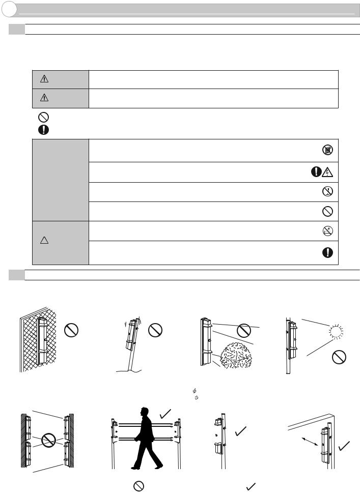
1-2 PRECAUTIONS
Do not install the unit on an unstable surface.
Do not install the pole in a |
Do not install the unit in a |
Do not install the receiver in a |
location where sufficient |
location where trees, leaves, or |
location where it is exposed to |
stability can not be ensured. |
other objects that may swing in |
direct sunlight. |
|
the wind and block the beam. |
|
[Receiver]
Do not allow the infrared beam from a different model to reach the receiver.
Receiver |
Transmitter |
Receiver |
Transmitter |
(different |
(different |
model) |
model) |
FOR UL/C-UL INSTALLATIONS ;
Install the unit at a height |
|
|
The pole size should be |
Install the unit at least 1 m (3.3 |
||||||||
where an object can be |
|
|
34 - 48 mm |
ft.) away from the wall or fence |
||||||||
detected without fail. |
|
|
( 1.34 - 1.89 inch). |
that may be running parallel to |
||||||||
|
|
|
|
|
|
|
|
|
|
the beam. |
||
|
|
|
|
|
|
|
|
|
|
|
|
|
|
|
|
|
|
|
|
|
|
|
|
|
|
|
|
|
|
|
|
|
|
|
|
|
|
|
|
|
|
|
|
|
|
|
|
|
|
|
|
At least 1 m (3.3 ft.)
Transmitter Receiver
This symbol indicates prohibition. |
This symbol indicates recommendation. |
•Reference to UL681, Standard for Installation and Classification of Burglar and Holdup Alarm System.
•Reference to CAN/ULC-S302, ULC Standard for Installation and Classification of Burglar Alarm Systems for Financial and Commercial Premises. Safes and Vaults, & CAN/ULC-S310, ULC Standards for Installation and Classification of Residential Burglar Alarm.
•Conduit is required for all Outdoor Use Application with Conduit Bracket Kit, Model CBR-4, employing appropriate wiring methods.
•Products to be installed within the protected premises.
-2-
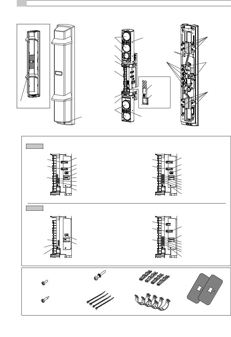
1-3 PARTS IDENTIFICATION
Cover |
|
Main unit |
|
Chassis |
|
Optical lens |
Viewfinder |
|
I.A.S.C lens |
|
|
[QDM only] |
Main unit base |
|
|
Mounting screw holes |
|
Horizontal alignment dial |
|
|
Vertical alignment dial |
Cut bush |
|
|
for wiring |
|
Terminals |
|
|
|
Tamper |
|
|
lock plate |
|
Vertical alignment dial |
Tamper |
|
button |
|
|
|
|
Beam blocking plate |
Horizontal alignment dial |
|
|
Optical lens |
|
|
Cover lock screw |
View finder |
Pole mounting screw holes
Wall mounting screw holes
Pole mounting screw holes
FUNCTION SETTING SECTION >>
SL-QDM
<Transmitter>
|
T |
Power supply selector |
Monitor jack (+) |
|
|
|
|
|
Monitor jack (-) |
|
Sound assist switch |
|
|
|
|
|
Beam power control selector |
|
|
Dip switch |
Alignment level |
|
Power indicator LED |
indicator LED |
|
Upper beam indicator LED |
|
|
Lower beam indicator LED |
|
|
Upper/Lower beam selection button |
|
<Receiver> |
|
|
R |
Power supply selector |
Monitor jack (+) |
|
|
|
|
|
Monitor jack (-) |
|
Sound assist switch |
|
|
|
|
|
Beam power control selector |
Alignment level |
|
Dip switch |
|
Alarm indicator LED |
|
indicator LED |
|
|
|
Alarm memory indicator LED |
|
|
|
|
|
|
Power indicator LED |
|
|
Upper beam indicator LED |
|
|
Lower beam indicator LED |
Upper/Lower beam selection button
SL-QDP
<Transmitter>
Power indicator LED
Upper beam indicator LED
Lower beam indicator LED


 T
T
Beam power control selector
Dip switch
 Upper/Lower beam selection button
|
<Receiver> |
|
Monitor jack (+) |
R |
|
|
||
Monitor jack (-) |
Sound assist switch |
|
|
||
|
Dip switch |
|
Alignment level |
Alarm indicator LED |
|
indicator LED |
||
Alarm memory indicator LED |
||
|
||
|
Power indicator LED |
|
|
Upper beam indicator LED |
|
|
Lower beam indicator LED |
|
|
Upper/Lower beam selection button |
ACCESSORIES >> |
|
|
|
M4×30 screws for pole mounting |
|
|
(with rubber washer): 8 |
Pole brackets: 4 |
3×6 self tapping for pole bracket: 4 |
|
|
|
|
4×20 self tapping for wall mounting: 4 |
|
|
|
|
Beam blocking plate: 2 |
Banding bands: 4 |
U-brackets: 4 |
(attached on the back of the cover) |
|
-3-
2 INSTALLATION
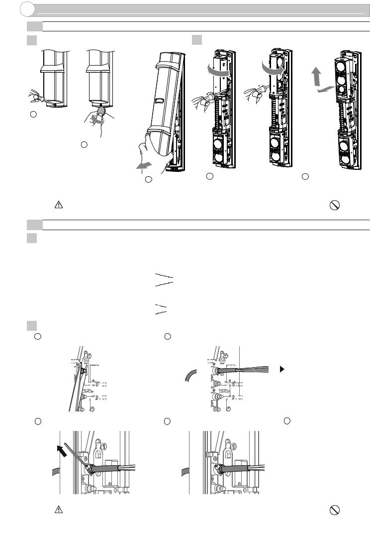
2-1 SEPARATING
1 Remove the cover. |
2 Remove the main unit from the chassis. |
|
|
|
1 |
3 |
6 |
4 
5
1 Loosen the |
|
cover lock screw. |
A coin |
|
(Not included) |
2 |
Twist it lightly. |
3 Pull
1 Turn the optical unit 90 degrees and loosen the screws (both sides).
2Pull the upper part of main unit, and raise it to remove.
Caution |
Do not place the main unit where it allows to incident direct sunlight to its optical lens during |
|
installation. Doing so may cause damage to the product. |
||
|
||
|
|
2-2 WIRING
1 Preparing the cut bush
Cut the wiring grommet required according to the wire diameter. Use the lidded grommet for the wiring hole not to be used. |
||||||||||||
(I.D. : Internal diameter) |
|
|
|
|
|
|
|
|
I.D. 10mm (0.39 inch) |
|||
|
|
|
|
|
|
|
|
|
|
|
I.D. |
8mm (0.31 inch) |
|
|
|
|
|
|
|
|
|
|
|
I.D. |
6mm (0.24 inch) |
|
|
|
|
|
|
|
|
|
|
|
I.D. |
4mm (0.16 inch) |
|
|
|
|
|
|
|
|
|
|
|
I.D. |
7mm (0.28 inch) |
|
|
|
|
|
|
|
|
|
|
|
||
|
|
|
|
|
|
|
|
|
|
|
||
|
|
|
|
|
|
|
|
|
|
|
||
|
|
|
|
|
|
|
|
|
|
|
I.D. |
6mm (0.24 inch) |
|
|
|
|
|
|
|
|
|
|
|
I.D. |
4mm (0.16 inch) |
|
|
|
|
|
|
|
|
|
|
|
|
|
|
|
|
|
|
|
|
|
|
|
|
|
|
2Threading the wire
1 Cut off the cut bush according to the cable size. |
2 Pass the cable through the cut bush. |
|
|||||||||||||||||||||||||||||||||||||||||
|
|
|
|
|
|
|
|
|
|
|
|
|
|
|
|
|
|
|
|
|
|
|
|
|
|
|
|
|
|
|
|
|
|
|
|
|
|
|
|
|
|
|
|
|
|
|
|
|
|
|
|
|
|
|
|
|
|
|
|
|
|
|
|
|
|
|
|
|
|
|
|
|
|
|
|
|
|
|
|
|
|
|
|
|
|
|
|
|
|
|
|
|
|
|
|
|
|
|
|
|
|
|
|
|
|
|
|
|
|
|
|
|
|
|
|
|
|
|
|
|
|
|
|
|
|
|
|
|
|
|
|
|
|
|
|
|
|
|
|
|
|
|
|
|
|
|
|
|
|
|
|
|
|
|
|
|
|
|
|
|
|
|
|
|
|
|
|
|
|
|
|
|
|
|
|
|
|
|
|
|
|
|
|
|
|
|
|
|
|
|
|
|
|
|
|
|
|
|
|
|
|
|
|
|
|
|
|
|
|
|
|
|
|
|
|
|
|
|
|
|
|
|
|
|
|
|
|
|
|
|
|
|
|
|
|
|
|
|
|
|
|
|
|
|
|
|
|
|
|
|
|
|
|
|
|
|
|
|
|
|
|
|
|
|
|
|
|
|
|
|
|
|
|
|
|
|
|
|
|
|
|
|
|
|
|
|
|
|
|
|
|
|
|
|
|
|
|
|
|
|
|
|
|
|
|
|
|
|
|
|
|
|
|
|
|
|
|
|
|
|
|
|
|
|
|
|
|
|
|
|
|
|
|
|
|
|
|
|
|
|
|
|
|
|
|
|
|
|
|
|
|
|
|
|
|
|
|
|
|
|
|
|
|
|
|
|
|
|
|
|
|
|
|
|
|
|
|
|
|
|
|
|
|
|
|
|
|
|
|
|
|
|
|
|
|
|
|
|
|
|
|
|
|
|
|
|
|
|
|
|
|
|
|
|
|
|
|
|
|
|
|
|
|
|
|
|
|
|
|
|
|
|
|
|
|
|
|
|
|
|
|
|
|
|
|
|
|
|
|
|
|
|
|
|
|
|
|
|
|
|
|
|
|
|
|
|
|
|
|
|
|
|
|
|
|
|
|
|
|
|
|
|
|
3 Tighten the cable with the banding band. |
4 Cut the excess portion of the banding band. |
5 Connect to the terminals |
Refer to "TERMINAL" on Page 5 to make connections to the terminals and refer to “OPTICAL ALIGNMENT” on Page 15 to make alignment for the maximum level of light reception.
Caution |
Do not exceed the voltage or current rating specified for any of the terminals during |
|
installation, doing so may cause fire or damage to the product. |
||
|
||
|
|
-4-
2-3 TERMINAL
|
SL-QDM |
<Transmitter> |
<Receiver> |
(1) |
+ |
POWER INPUT |
|
(2) |
- |
10.5-30VDC [ Normal ] |
|
3.6VDC [ SBU-4 ]* |
|||
(3) |
|
||
|
SPARE |
||
(4) |
|
||
|
|
||
(5) |
|
ALARM INPUT |
|
(6) |
|
||
|
|
(7)LOW BATTERY INPUT
(using with SBU-4)*
(8) |
TAMPER |
|
(9) |
||
OUTPUT (N.C.)** |
(1) |
+ |
POWER INPUT |
|
(2) |
- |
10.5-30VDC [ Normal ] |
|
3.6VDC [ SBU-4 ]* |
|||
(3) |
|
||
|
SPARE |
||
(4) |
|
||
|
|
||
(5) |
N.O. |
D.Q. OUTPUT/ |
|
(6) |
N.C. |
||
LOW BATTERY |
|||
|
|
||
(7) |
COM. |
OUTPUT* ** |
|
(8) |
COM. |
|
|
(9) |
N.C. |
ALARM OUTPUT** |
|
|
|||
(10) N.O. |
|
||
(11) |
|
ALARM MEMORY INPUT |
|
(12) |
|
LOW BATTERY INPUT |
|
(13) |
|
(using with SBU-4)* |
|
|
TAMPER OUTPUT** |
||
(14) |
|
||
|
(N.C.) |
||
|
|
||
SL-QDP
<Transmitter> |
|
<Receiver> |
|
||
(1) |
+ |
POWER INPUT |
(1) |
+ |
POWER INPUT |
(2) |
- |
10.5-30VDC |
(2) |
- |
10.5-30VDC |
(3) |
|
SPARE |
(3) |
|
SPARE |
(4) |
|
(4) |
|
||
|
|
|
|
||
|
|
|
(5) |
N.O. |
|
|
|
|
(6) |
N.C. |
D.Q. OUTPUT |
|
|
|
|
|
|
|
|
|
(7) |
COM. |
|
|
|
|
(8) |
COM. |
|
|
|
|
(9) |
N.C. |
ALARM OUTPUT** |
|
|
|
|
||
|
|
|
(10) N.O. |
|
|
|
|
|
(11) |
|
ALARM MEMORY INPUT |
|
|
|
(12) |
|
SPARE |
(5) |
|
TAMPER |
(13) |
|
TAMPER OUTPUT** |
(6) |
|
(14) |
|
||
|
OUTPUT (N.C.)** |
|
|||
|
|
(N.C.) |
|||
|
|
|
|
|
|
NOTE>>
Connect POWER INPUT - terminal(2) when wiring LOW BATTERY INPUT* terminal(7) of the transmitter,
ALARM MEMORY INPUT terminal(11) and LOW BATTERY INPUT terminal(12) of the receiver.
|
|
|
|
|
* SBU-4 and its low battery input/output function not evaluated by UL |
** All outputs are power-limited. |
||||||||||
|
|
|
|
|
|
|
|
|
|
|
|
|
|
|
|
|
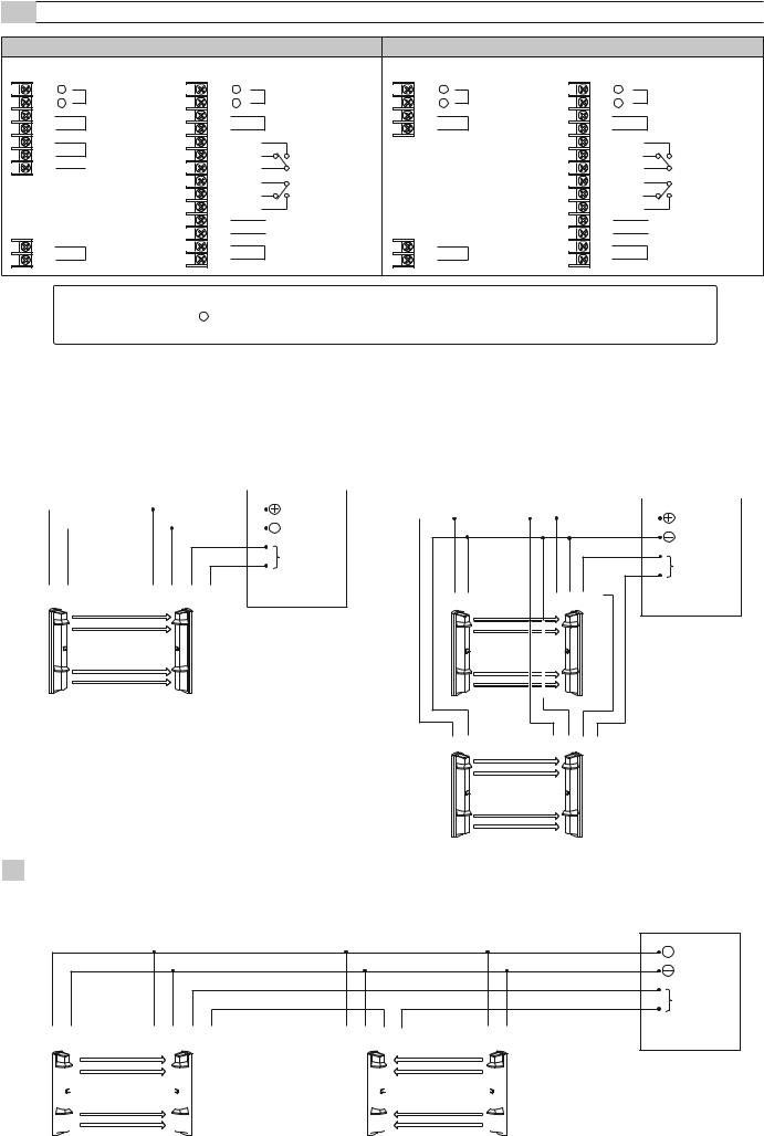
2-4 |
WIRING DIAGRAM |
|
|
|
|
|
|
|||||||||
|
|
|
|
|
|
|
|
|
|
|
|
|
|
|
||
|
1 |
|
|
|
|
|
|
|||||||||
|
1 Set |
2 |
|
2 Sets Stacking |
||||||||||||
Connect the power supplies in parallel. |
Connect the power supply in parallel. Connect the units serially for a |
|||||||||||||||
|
|
|
|
|
|
|||||||||||
|
|
|
|
|
|
|
|
|
|
|
normally closed alarm output and in parallel for a normally open |
|||||
|
|
|
|
|
|
|
|
|
|
|
output (the figure below shows an example for a normally closed |
|||||
|
|
|
|
|
|
CONTROL PANEL*1 |
alarm output). |
|||||||||
|
|
|
|
|
|
|
|
|
CONTROL PANEL*1 |
|||||||
|
|
|
|
|
|
|
|
|
POWER*2 |
|
|
|
|
|||
|
|
|
|
|
|
|
|
|
|
|
|
|
POWER*2 |
|
||
|
|
|
|
|
|
|
|
|
|
|
||||||
|
|
|
|
|
|
|
|
|
|
|
|
|
||||
|
|
|
|
|
|
|
|
|
|
|
|
|
|
|
||
|
|
|
|
|
ALARM |
|
ALARM |
|
|
|
|
|
N.C. |
|
|
|
|
|
|
|
|
N.C. |
|
|
|
|
|
|
|
|
|
(1) |
(2) |
(1) |
(2) |
(8) |
(9) |
(1)(2) |
(1)(2)(8)(9) |
|
|
|
|
|
|
||
|
|
|
|
|
|
Ch1 |
Ch1 |
Transmitter |
|
Receiver |
|
|
|
||
|
|
|
|
|
|
(1) (2) |
(1) (2)(8)(9) |
*1 CONTROL PANEL = UL/c-UL listed burglar alarm control panel |
|
|
|||||
*2 POWER = power limited output |
|
|
Ch3 |
Ch3 |
|||
|
|
|
|
|
|
||
|
|
|
|
|
|
Transmitter |
Receiver |
32 Sets in the line
Connect the power supply in parallel. Connect the units serially for a normally closed alarm output and in parallel for a normally open output (the figure below shows an example for a normally closed alarm output).
CONTROL PANEL*1
POWER*2
ALARM
N.C.
(1) |
(2) |
(1) |
(2) |
(8) |
(9) |
(1) |
(2) |
(8) |
(9) |
(1) |
(2) |
||||||||||
|
|
|
|
|
|
|
|
|
|
|
|
|
|
|
|
|
|
|
|
|
|
|
|
|
|
|
|
|
|
|
|
|
|
|
|
|
|
|
|
|
|
|
|
|
|
|
|
|
|
|
|
|
|
|
|
|
|
|
|
|
|
|
|
|
|
|
|
|
|
|
|
|
|
|
|
|
|
|
|
|
|
|
|
|
|
|
|
|
|
|
|
|
|
|
|
|
|
|
|
|
|
|
|
|
|
|
|
|
|
|
|
|
|
|
|
|
|
|
|
|
|
|
|
|
|
|
|
|
|
|
|
|
|
|
|
|
|
|
|
|
|
|
|
|
|
|
|
|
|
|
|
|
|
|
|
|
|
|
|
|
|
|
|
|
|
|
|
|
|
|
|
|
|
|
|
Transmitter |
Receiver |
Receiver |
Transmitter |
-5-

2-5 WIRING DISTANCE BETWEEN POWER SUPPLY AND DETECTOR
-Ensure that the wiring distance from the power supply is within the range shown in the table below.
-When using two or more units on one wire, the maximum length is obtained by dividing the wire length listed below by the number of units used.
MODEL |
SL-200QDM / SL-350QDM / SL-650QDM |
||
SL-200QDP / SL-350QDP / SL-650QDP |
|||
|
|||
WIRE SIZE |
12 VDC |
24 VDC |
|
|
|
|
|
0.33 mm2 |
600 m |
2,100 m |
|
(AWG22) |
(2,000 ft.) |
(7,000 ft.) |
|
|
|
|
|
0.52 mm2 |
900 m |
3,300 m |
|
(AWG20) |
(3,000 ft.) |
(10,000 ft.) |
|
|
|
|
|
0.83 mm2 |
1,500 m |
5,300 m |
|
(AWG18) |
(4,900 ft.) |
(17,000 ft.) |
|
|
|
|
|
1.31 mm2 |
2,500 m |
8,300 m |
|
(AWG16) |
(8,000 ft.) |
(27,000 ft.) |
|
|
|
|
|
NOTE>>
UL/c-UL requires to be connected to a UL/c-UL Listed burglar alarm power limited power supply of providing a nominal input of 12 VDC (10.5 to 30 VDC) 30 mA (SL-200/350/650 QDM) or 22 mA (SL-200/350/650 QDP), and battery standby time of 4 hours.
Wiring method shall be in accordance with the National Electrical Code (ANSI / NFPA 70), Canadian Electrical Code, Part 1 (CSA C22.1) Safety Standard for Electrical Installations, local codes, and the authorities having jurisdiction.
2-6 WALL MOUNTING
1Open the wiring guide on the back of the chassis using pliers as shown.
2Pull the waterproof packing (x2) marked as " " at the center of the chassis.
<After the cutting>
[ Upper ] [ Lower ]
3 Mount the chassis to the wall. 4 Put the waterproof packing back in place.
Side wall
|
If two detectors |
|
are installed, the |
Distance from the side wall: |
distance between |
at least 1m |
the upper and |
|
lower detector |
|
should be at least |
|
20 mm. |
|
Pitch: 83.5 mm |
|
For connection |
|
to gang electric |
|
box |
4×20 self tapping |
|
(with rubber washer) |
|
NOTE>>
Install the unit vertically at a height where an object can be detected without fail. In case to be stacked, be careful to cover the detection area totally.
-6-
 Loading...