

Optex SS Checker SC-T4 Instruction Manual

SC-T4
Thank you very much for purchasing OPTEX
Transmitter SC-T4.
All of this instruction manual must be read before
operation of the Transmitter SC-T4, for safe and proper
operation.
This instruction manual should be kept for future
reference such as maintenance.
Transmitter
Instruction Manual
2006.8 59-1362-0
For more information on OPTEX products, contact your
dealer or visit our website listed below;
OPTEX CO., LTD.
5-8-12 Ogoto Otsu Shiga 520-0101 Japan
tel : +81-77-579-8690
fax : +81-77-579-7120
E-mail : env@optex.co.jp
website : http://www.optex.co.jp/env/
Distributed by
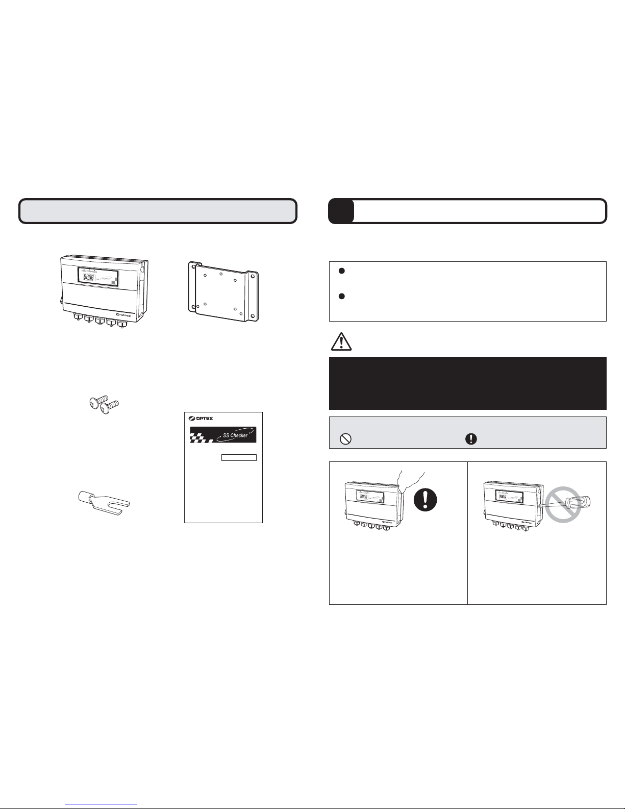
The Contents of Packaging
Transmitter
Instruction Manual20 Y-terminal
Mounting Bracket
2 Transmitter Fixing Screw
In the unlikely event that there are any missing components or defects,
please contact your dealer.
SC-T4
Thank you very much for purchasing OPTEX
Transmitter SC-T4.
All of this instruction manual must be read before
operation of the Transmitter SC-T4, for safe and
proper operation.
This instruction manual should be kept for future
reference such as maintenance.
Transmitter
Instruction Manual
0
Please thoroughly read the "For safe use" before using the SC-T4
properly.
Because these precautions are related to failure or malfunction,
observe the precautions for use without fail.
In order to use the SC-T4 properly,
observe the following precautions.
Precautions which are the cause of failure:
The SC-T4 is used exclusively to SS Checker (Detector).
Accordingly, do not connect other equipment.
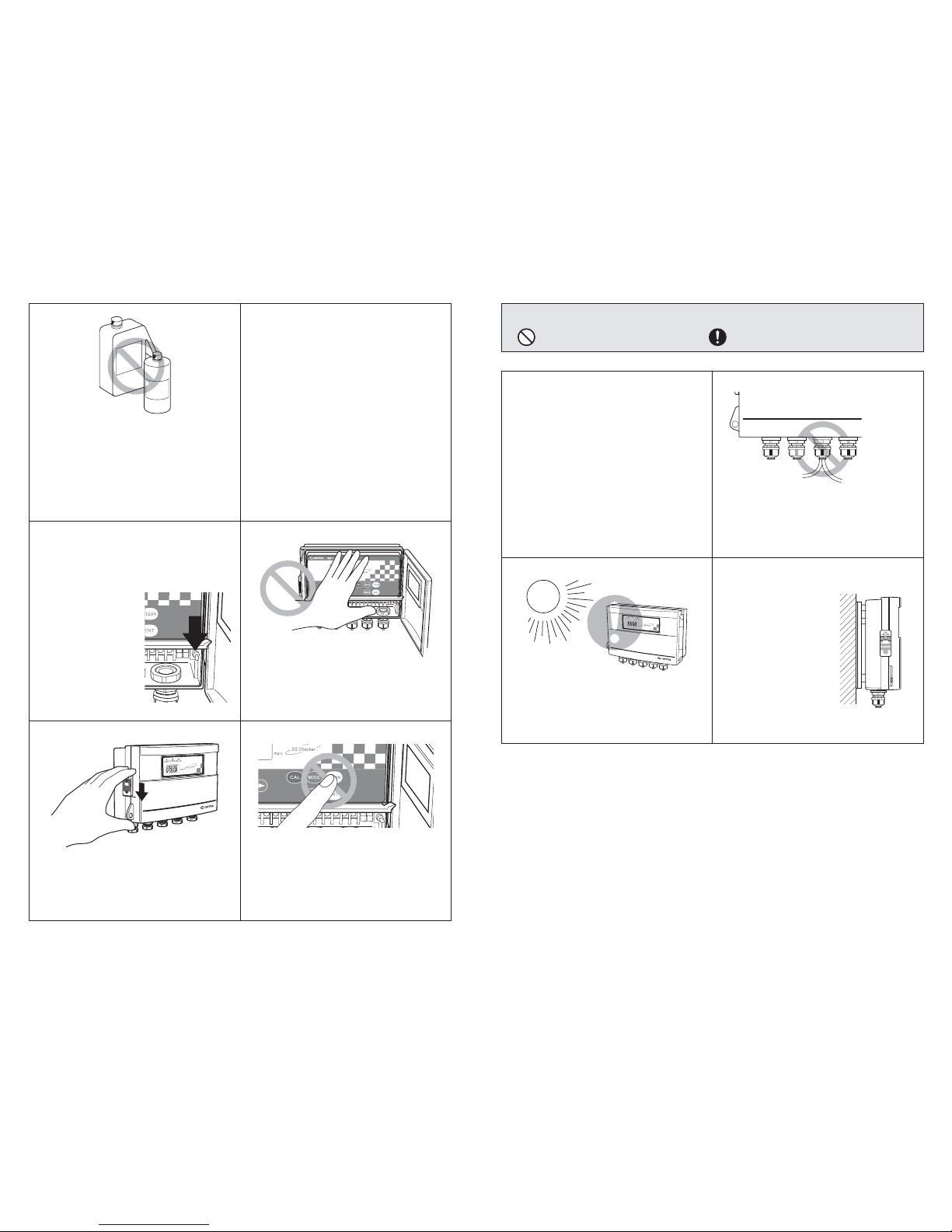
●Precautions which are the cause of failure
●Precautions related to measurement
・Do not disassemble or modify the
Transmitter. Disassembly or
modification may cause fire or an
electric shock because there are highvoltage parts inside the Transmitter.
・Turn off the Power immediately in the
unlikely event that there occur any
abnormalities such as smoke or
abnormal noise. Otherwise it may
cause fire or an electric shock.
[
Be sure to read this instruction manual in order
to use the Transmitter SC-T4 properly.]
1
For safe use
" " denotes "Prohibited action", and " " denotes "Required action".
Power (OFF
)
1
2 3
・Be sure to use the power supply of
100 to 240 VAC.
Otherwise it may cause fire or
electric shock.
・Do not wipe the Transmitter with
solvent. It may cause failure.
・To clean the Transmitter, first wipe
away lightly with a clean soft cloth
damped by diluted mild detergent
solution and then wipe off moisture
with a dry clean soft cloth.
100 to 240 VAC
Organic
Solvent
Thinner
etc.
・There are high
voltage parts inside
the Transmitter.
Failure to observe
this precaution may
cause fire or an
electric shock.
・Do not give a strong shock to the
Transmitter.
・Do not press the CLEAN button, while
the SS Checker (Detector) is in the air.
・Make sure that the Cover is locked
without fail. Otherwise, protective
structure may not function adequately.
Keep the Power off during
installation and wiring operations.
Precautions which are the cause of failure:
" " denotes "Prohibited action", and " " denotes "Required action".
・Use Cable Clamps attached to the
transmitter for wiring. When the piping
are directly connected with the
transmitter, take a corrective action
such as caulking against intrusion of
gas because corrosive gas is in danger
of intruding through the piping, etc. into
the Transmitter.
・Do not bind the signal output cable with
the power cable or do not put them in
the one Cable Clamp.
・Install the transmitter
with attached
Mounting Bracket.
・Install the transmitter at a place
ventilating well and avoiding direct
sunlight.
4 5
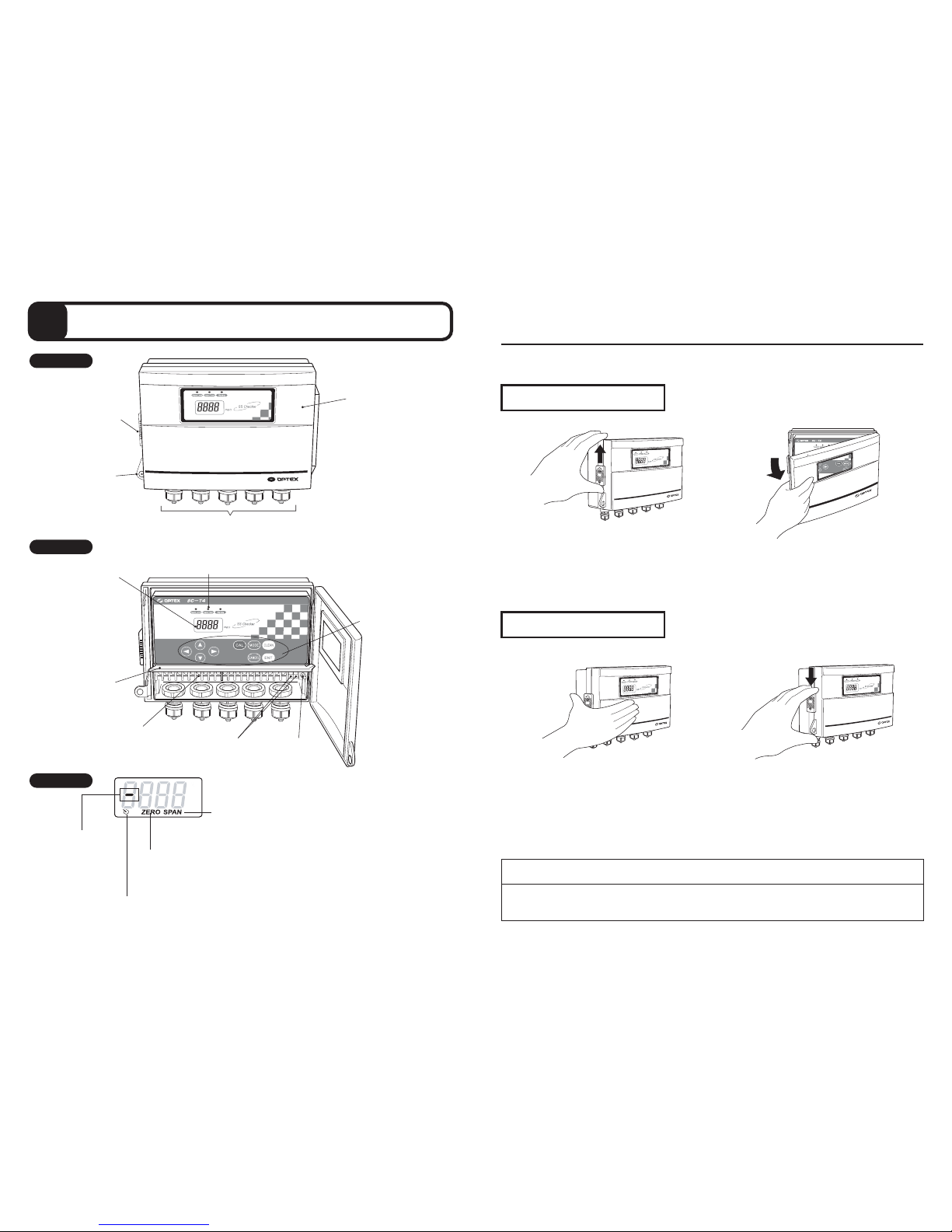
Minus Indicator
Signal Output Response Time Indicator
During Signal Output Response Time setting: Blinking
SPAN Indicator
During Span Adjustment: Blinking
During Signal Output (4mA) Adjustment: On
During Signal Output (20mA) Adjustment: Blinking
ZERO Indicator
During ZERO Adjustment: Blinking
During Signal Output (4mA) Adjustment: Blinking
During Signal Output (20mA) Adjustment: On
Transmitter
Operation panel
Display
2
External Features
Cover
Cable Clamps
Key Hook
Lock Lever
Power SwitchCircuit Breakers
Terminal Block
Operation Buttons
Display
Terminal Cover
Alarm Level Indicator (Green)
Alarm Timer Indicator (Green)
Warning Indicator (Red
)
How to open the Cover
How to close the Cover
・Make sure that the Cover is locked without fail. Otherwise, protective structure may
not function adequately.
Cover Opening & Closing Procedure
1. Slide up the Lock Lever.
2. Pull the Cover.
1. Close the Cover securely.
2. Slide down the Lock Lever
until it stops.
CAUTION:
6 7
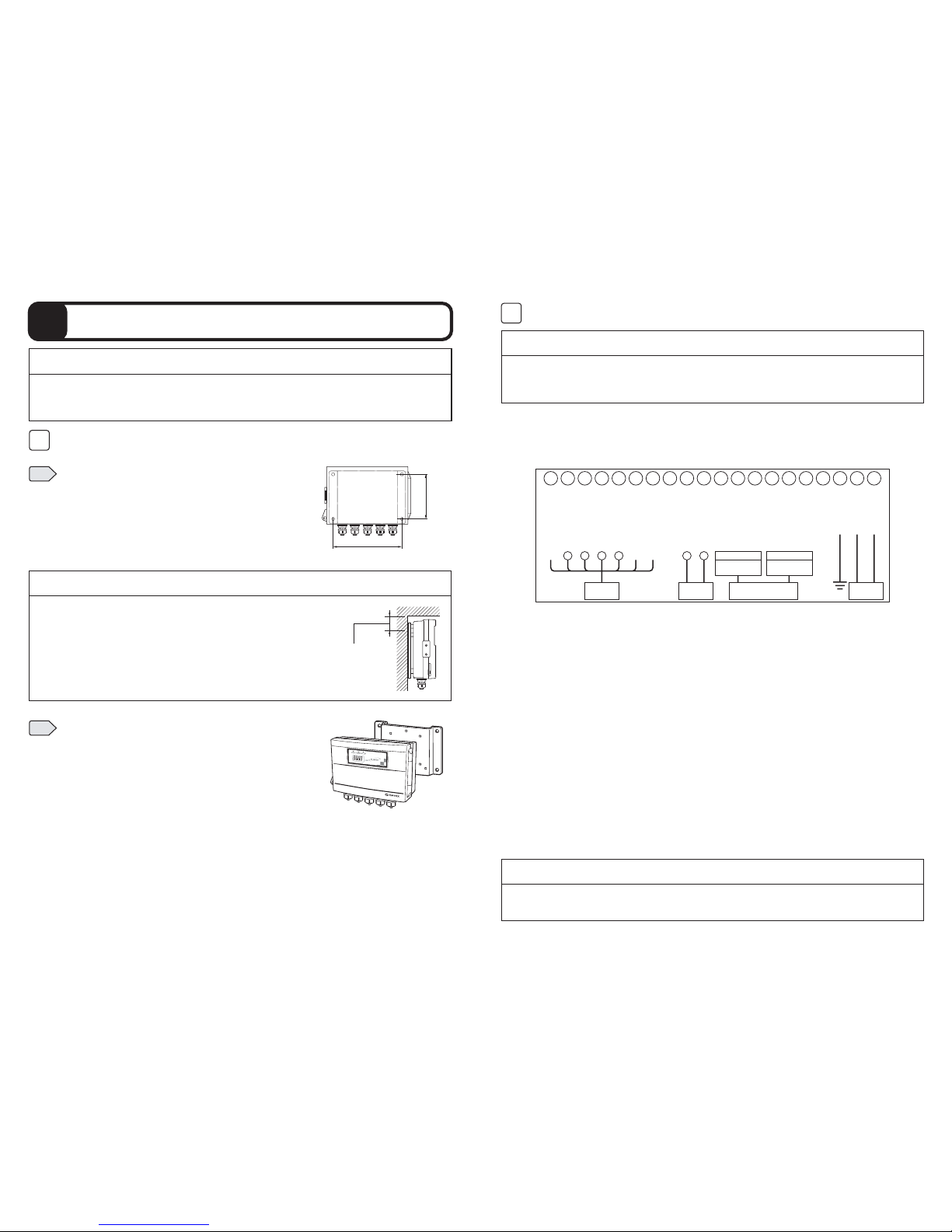
3
Installation
Fit the Mounting Bracket attached to the
Transmitter with the Fitting Screws.
1
Install the Mounting Bracket on the wall
and so forth. For mounting pitch, refer
to the Fig. to the right.
Installation1
125mm
186mm
(
Mounting Hole Φ9
)
・ Install the Transmitter at a place ventilating well and avoiding direct sunlight.
・ Install the Transmitter with Mounting Bracket.
・ Close the Cover securely after installation is completed.
CAUTION:
・If there is a projection on the mounting surface, separate
40 mm or more from the upper Mounting Holes of the
Mounting Bracket (See Fig. to the right).
40 mm or more from the
center of the upper
mounting holes
CAUTION:
2
・ Make sure that the Circuit Breaker is normal
(
OFF) position (Refer to
[8]
Troubleshooting).
Wiring
① 〜 ⑳・ Compatible cable diameter with the Cable Clamps is 6 〜 8 mm.
① 〜 ⑦・ Use a shielded cable with nominal sectional area of 0.2 〜 1.25 mm
2
for the
Detector Cable.
・ For extension of the Detector Cable, refer to
[3]
Detector Cable Extension. Use
a device such as a Pull-box if necessary.
⑨ 〜 ⑩ ・ Use a shielded cable with nominal sectional area of 0.75 to 1.25 mm
2
for a
Signal Output Cable.
・ For connection to the Signal Output terminal, load resistance should be 300 Ω
Max (including wiring resistance).
⑪ 〜 ⑯ ・ For connection to the Self Checking Relay Output terminal and Alarm Relay
Output terminal, load resistance should be 240 VAC and 1A Max.
Although a protective circuit is built in to prevent from overcurrent due to
thunderbolt, it is recommended to use fuses with rated current of 2A Max for the
purpose of improvement of safety.
⑱
・ Carry out grounding work.
⑲ 〜 ⑳ ・ Use a cross-linked polyethylene insulating vinyl sheath cable
with nominal
sectional area of 0.75 to 1.25 mm
2
for the power cable.
2
・Keep the Power off during wiring operations. Otherwise it may cause fire or an
electric shock.
・Wire the Power Cable, at the end of wiring operation.
CAUTION:
1
2 3 456 7 8910 11 121314 15 161718 19 20
F.G.
Spare
Spare
CalibrationSignalOutput
AlarmRelay
AlarmRelay
AlarmRelay
SelfChekingRelay
SelfChekingRelay
SelfChekingRelay
SelfCheckingInput
AnalogSignalInput
AnalogSignalOutput
AnalogSignalOutput
AnalogSignalInput
PowerSupply
PowerSupply
12VPowerSupply
12VGround
ShieldLine
(Blue)(Brown)(Black)(White)(Green)(Red)
COM NCNOCOM NCNO
−
+− +− +
ControlPanel
etc.
Detector
AC100240V
50/60Hz
Recorder
etc.
SelfChecking
RelayOutput
Alarm
RelayOutput
4‑20mA
〜
Controller Terminal Block
Reference:
・When the Detector is in the air, analog
(
4-20mA) signal output becomes
approximately 6mA,
 Loading...