

Optex PCU-5, Smartline Installation Instructions Manual
BATTERY OPERATED
BATTERY OPERATED
PHOTOELECTRIC DETECTOR
PHOTOELECTRIC DETECTOR
Smart Line series
Smart Line series
OPTION
OPTION
INSTALLATIONS
™
™
INSTALLATION INSTRUCTIONS
Power Convertor Unit
Voltage convertor unit used to enable wired
operation of the detector.
PCU-5
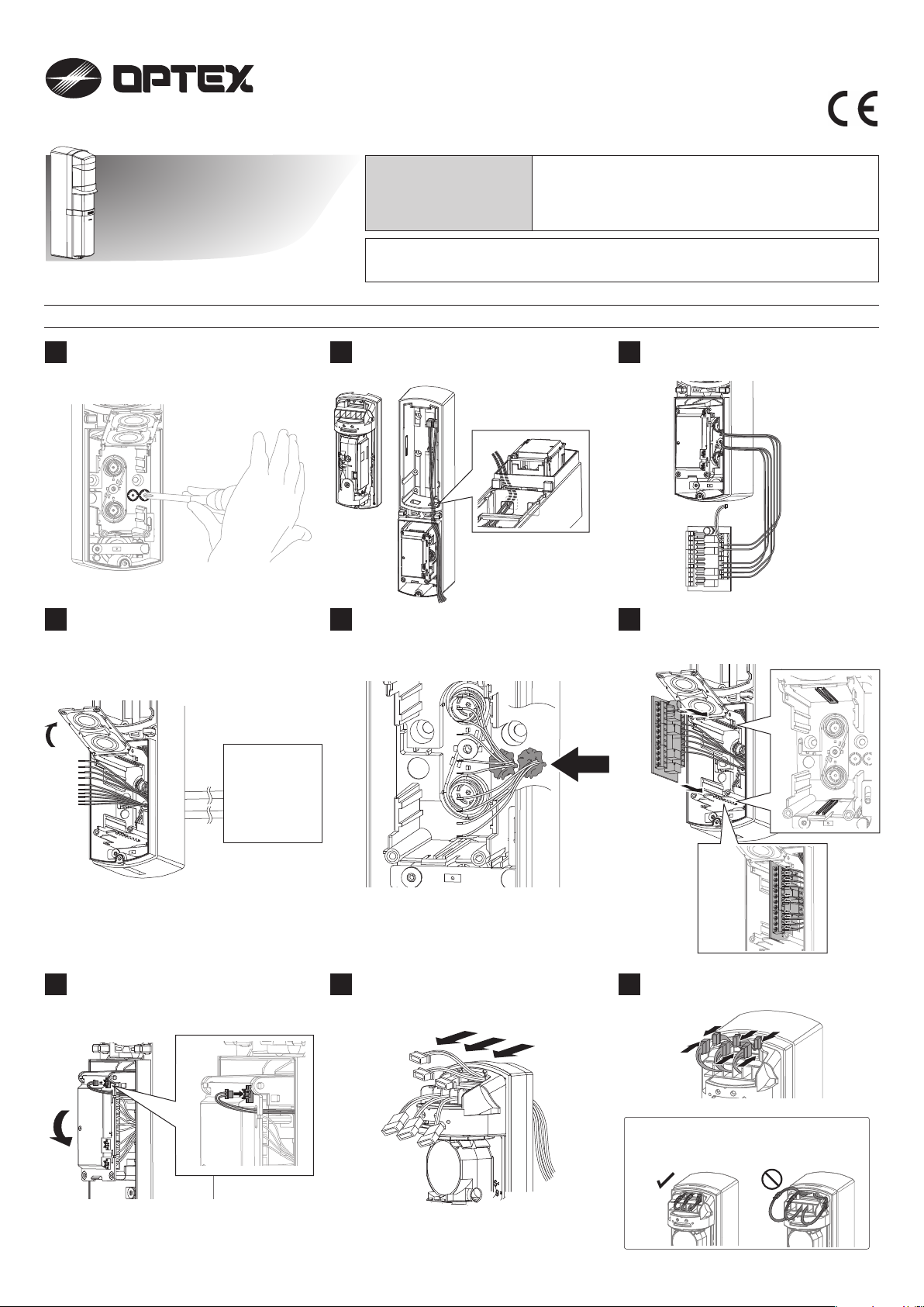
PARTS IDENTIFICATION
PCU-5 ×1, Putty ×2
No. 59-2069-0
Using a screwdriver or similar tool, break
1 2 3
the knockout position in the back box as
shown.
Open the battery plate and then route the
4 5
control panel wires from the rear of the back
box through the knockout holes. Adjust the
wires so that they extend about 100 mm
from the holes.
Controlpanel
Route connector cables (Alarm, Low battery
and Tamper) in the back box through the
hole to the battery box.
Fill the holes with the wires using the
supplied putty.
Connect the connector cable to the
terminals of PCU-5.
Insert PCU-5 into the slots on the back
6
box and then connect the wires to the
PCU-5 terminals.
Close the battery plate and connect PCU-5
7
male connector to the female connector of
the battery plate.
Route the three connectors of the back box
8 9
through the slit on the upper part of the
main unit.
-1-
Attach the connectors.
Note>>
Put the cables in order not to be caught
between the main unit and cover.
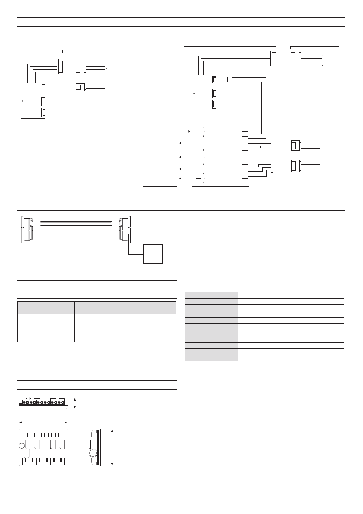
SYSTEM DIAGRAM
Transmitter
Back box
Main unit
Receiver
Red
Black
PCU-5
BCU-4
Battery plate
Green
Blue
Battery plate
Control panel
Power
10 - 30V
Alarm
DQ*
Low battery
* The DQ function is not provided
with the SL-TNR.
Tamper
FUNCTION TO TRANSMIT LOW-BATTERY SIGNAL
PCU-5
BCU-4
+
–
C
NC
NO
C
NC
NO
C
NC
C
NC
Back box
PCU-5
Power
Alarm
DQ*
Low battery
Tamper
NC
NC
NC
NC
Main unit
Red
Black
+
–
C
C
C
C
Yellow
Orange
Brown
Green
Blue
Purple
Gray
Low battery signal
Control
panel
WIRING DISTANCE BETWEEN POWER
SUPPLY AND DETECTOR
Wire size
0.33mm2 (AWG22)
2
0.52mm
0.83mm
1.31mm
(AWG20)
2
(AWG18)
2
(AWG16)
180m (600ft.)
280m (900ft.)
450m (1,500ft.)
700m (2,300ft.)
Power supply voltage
12VDC 24VDC
1,200m (4,000ft.)
1,800m (6,000ft.)
3,000m (10,000ft.)
4,500m (14,500ft.)
DIMENSIONS
The low-battery signals are transmitted from the transmitter using IR
beams.
This function enables to eliminate the need to install a wireless transmitter
in the photoelectric transmitter.
SPECIFICATIONS
Power input
Current draw
Output voltage
Output current
Alarm output
D.Q. output
Low battery output
Tamper output
Operating temperature
Operating humidity
Dimension
H×W×D mm (inch): 71 (2.8) × 53 (2.1) × 20 (0.8)
OPTEX CO., LTD. (JAPAN)
URL: http://www.optex.net/
10.5 - 30 VDC
80mA (max.)
Approx. 3.6 to 3.9 VDC
10mA (max.)
Form C relay ; 30VDC. 0.2A
Form C relay ; 30VDC. 0.2A
N.C. relay ; 30VDC. 0.2A
N.C. relay ; 30VDC. 0.2A
-20°C to 60°C (-4°F to 140°F)
95% (max.)
71 (2.8)
20 (0.8)
53 (2.1)
Unit: mm (inch)
OPTEX INC. (U.S.)
URL: http://www.optexamerica.com/
OPTEX DO BRASIL LTDA. (Brazil)
URL: http://www.optex.net/br/es/sec/
OPTEX (EUROPE) LTD. /
EMEA HQ (U.K.)
URL: http://www.optexeurope.com/
OPTEX TECHNOLOGIES B.V.
(The Netherlands)
URL: http://www.optex.nl/
OPTEX SECURITY SAS (France)
URL: http://www.optex-security.com/
-2-
OPTEX SECURITY Sp.z o.o. (Poland)
URL: http://www.optex.com.pl/
OPTEX PINNACLE INDIA,
PVT., LTD. (India)
URL: http://www.optex.net./in/en/sec/
OPTEX KOREA CO.,LTD. (Korea)
URL: http://www.optexkorea.com/
OPTEX (DONGGUAN) CO.,LTD.
SHANGHAI OFFICE (China)
URL: http://www.optexchina.com/
 Loading...