

Page 1
No. 59-1882-0
INSTALLATION INSTRUCTIONS
PHOTOELECTRIC DETECTOR
PHOTOELECTRIC DETECTOR
Smart Line series
Smart Line series
FEATURES
• Quad high power beams
• Smart design
- Slim body design
- Easy-to-see vivid interior color for optical alignment
- IP65 waterproof structure
CONTENTS
1
INTRODUCTION
1-1 BEFORE YOUR OPERATION .......................1
1-2 PRECAUTIONS
1-3 PARTS IDENTIFICATION
2
INSTALLATION
2-1 SEPARATING................................................. 3
2-2 WIRING.......................................................... 3
2-3 TERMINAL .....................................................4
2-4 WIRING DIAGRAM ........................................ 4
2-5 WIRING DISTANCE BETWEEN POWER
SUPPLY AND DETECTOR ............................ 4
2-6 WALL MOUNTING......................................... 5
2-7 POLE MOUNTING ......................................... 6
.......................................................
™
™
.....................................
Model
SL-200QN
SL-350QN
SL-650QN
• View finder with 2X magnification
• Various options (refer to page 12)
( HU-3, ABC-4, BC-4, CBR-4, PSC-4, BAU-4 )
• Beam interruption adjustment function
• Tamper function
2-8 MOUNTING IN THE BEAM TOWER..............7
3
FUNCTION SETTING
2
2
3-1 BEAM INTERRUPTION ADJUSTMENT........ 8
4
OPTICAL ALIGNMENT
4-1 OPTICAL ALIGNMENT FOR UPPER AND
LOWER BEAM............................................... 8
OPERATION CHECK........................................... 9
5
OPTIONAL SETTING
6
6-1 HEATER UNIT HU-3 (OPTION) .................... 10
7
DIMENSIONS...................................................... 10
TROUBLESHOOTING ........................................ 11
8
9
SPECIFICATIONS............................................... 11
10
OPTIONS ............................................................ 12
Detection range
60m/200ft.
100m/350ft.
200m/650ft.
INTRODUCTION
1
BEFORE YOUR OPERATION
1-1
• Read this instruction manual carefully prior to installation.
• After reading, store this manual carefully in an easily accessible place for reference.
• This manual uses the following warning indications for correct use of the product, harm to you or other people and damage to your assets, which
are described below. Be sure to understand the description before reading the rest of this manual.
Warning
Caution
This symbol indicates prohibition. The specific prohibited action is provided in and/or around the figure.
This symbol requires an action or gives an instruction.
Warning
Caution
Failure to follow the instructions provided with this indication and improper handling may cause
death or serious injury.
Failure to follow the instructions provided with this indication and improper handling may cause
injury and/or property damage.
Do not use the product for purposes other than the detection of moving objects such as
people and vehicles. Do not use the product to activate a shutter, etc., which may
cause an accident.
Do not touch the unit base or power terminals of the product with a wet hand (do not
touch when the product is wet with rain, etc.). It may cause electric shock.
Never attempt to disassemble or repair the product. It may cause fire or damage to the
devices.
Do not exceed the voltage or current rating specified for any of the terminals during
installation, doing so may cause fire or damage to the devices.
Do not pour water over the product with a bucket, hose, etc. The water may enter,
which may cause damage to the devices.
Clean and check the product periodically for safe use. If any problem is found, do not
attempt to use the product as it is and have the product repaired by a professional
engineer or electrician.
-1-
Page 2
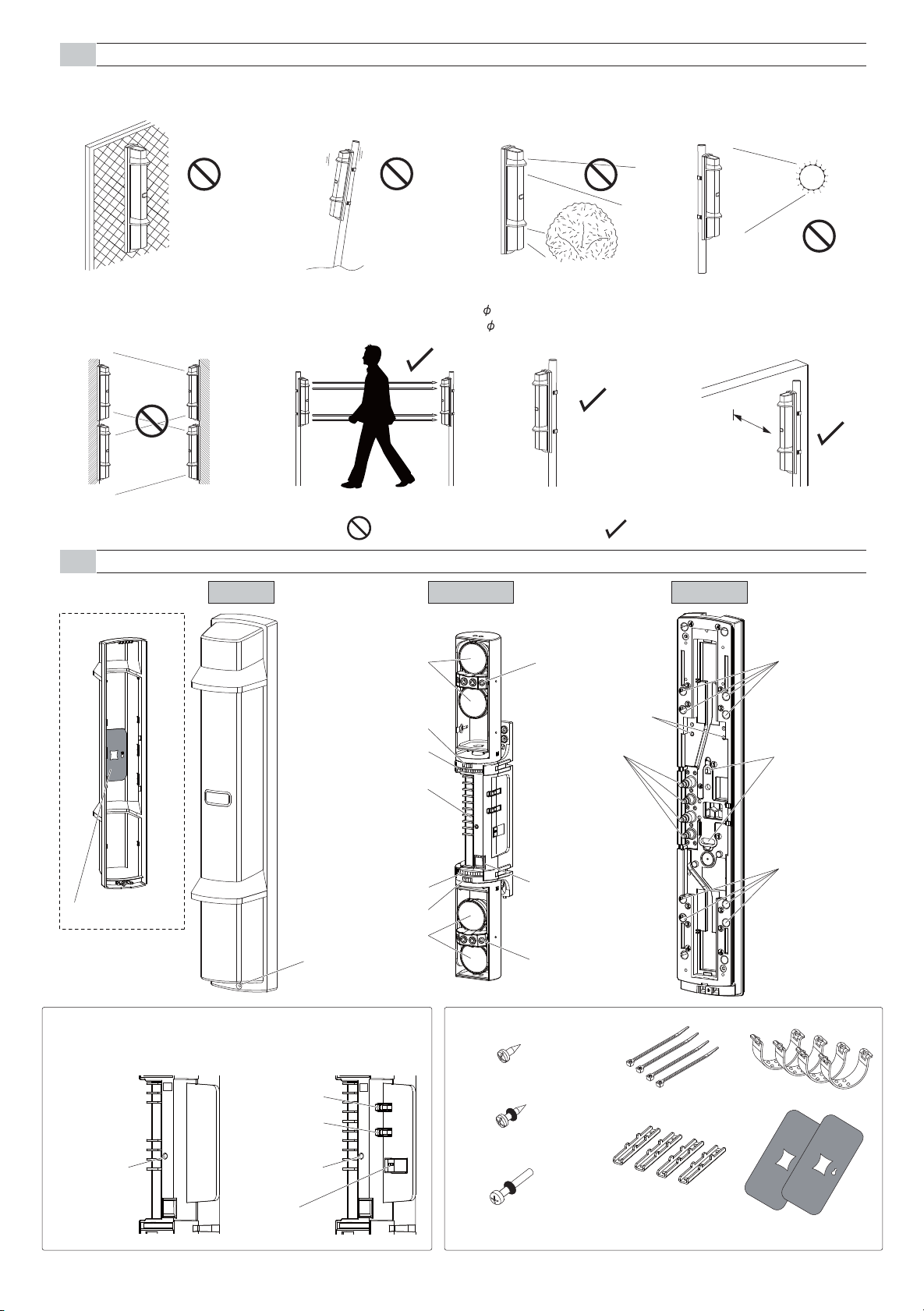
PRECAUTIONS
1-2
Do not install the unit on an
unstable surface.
Do not install the pole in a
location where sufficient
stability can not be ensured.
Do not install the unit in a
location where trees, leaves, or
other objects that may swing in
the wind and block the beam.
Do not install the receiver in a
location where it is exposed to
direct sunlight.
[Receiver]
Do not allow the infrared beam
from another detector to reach
the receiver.
Receiver
Receiver
(another
detector)
PARTS IDENTIFICATION
1-3
Transmitter
Transmitter
(another
detector)
Cover
Install the unit at a height
where an object can be
detected without fail.
Transmitter
This symbol indicates prohibition.
Optical lens
Horizontal alignment dial
Vertical alignment dial
Terminals
Receiver
Main unit
The pole size should be
34 - 48 mm
( 1.34 - 1.89 inch).
View finder
Main unit base
Mounting screw holes
Cut bush
for wiring
Install the unit at least 1 m (3.3
ft.) away from the wall or fence
that may be running parallel to
the beam.
At least 1 m (3.3 ft.)
This symbol indicates recommendation.
Chassis
Pole mounting
screw holes
Wall mounting
screw holes
Tamper button
Beam blocking plate
Vertical alignment dial
Horizontal alignment dial
Optical lens
Cover lock screw
View finder
FUNCTION SETTING SECTION >> ACCESSORIES >>
<Transmitter> <Receiver>
3×6 self tapping for pole bracket: 4
4×20 self tapping for wall mounting
(with rubber washer): 4
M4×30 screws for pole mounting
(with rubber washer): 8
Power indicator
T
Monitor jack (+)
Monitor jack (-)
Alarm indicator
Dip switch
R
-2-
Banding bands: 4
Pole brackets: 4
Pole mounting
screw holes
U-brackets: 4
Beam blocking plate: 2
(attached on the back of the cover)
Page 3
INSTALLATION
2
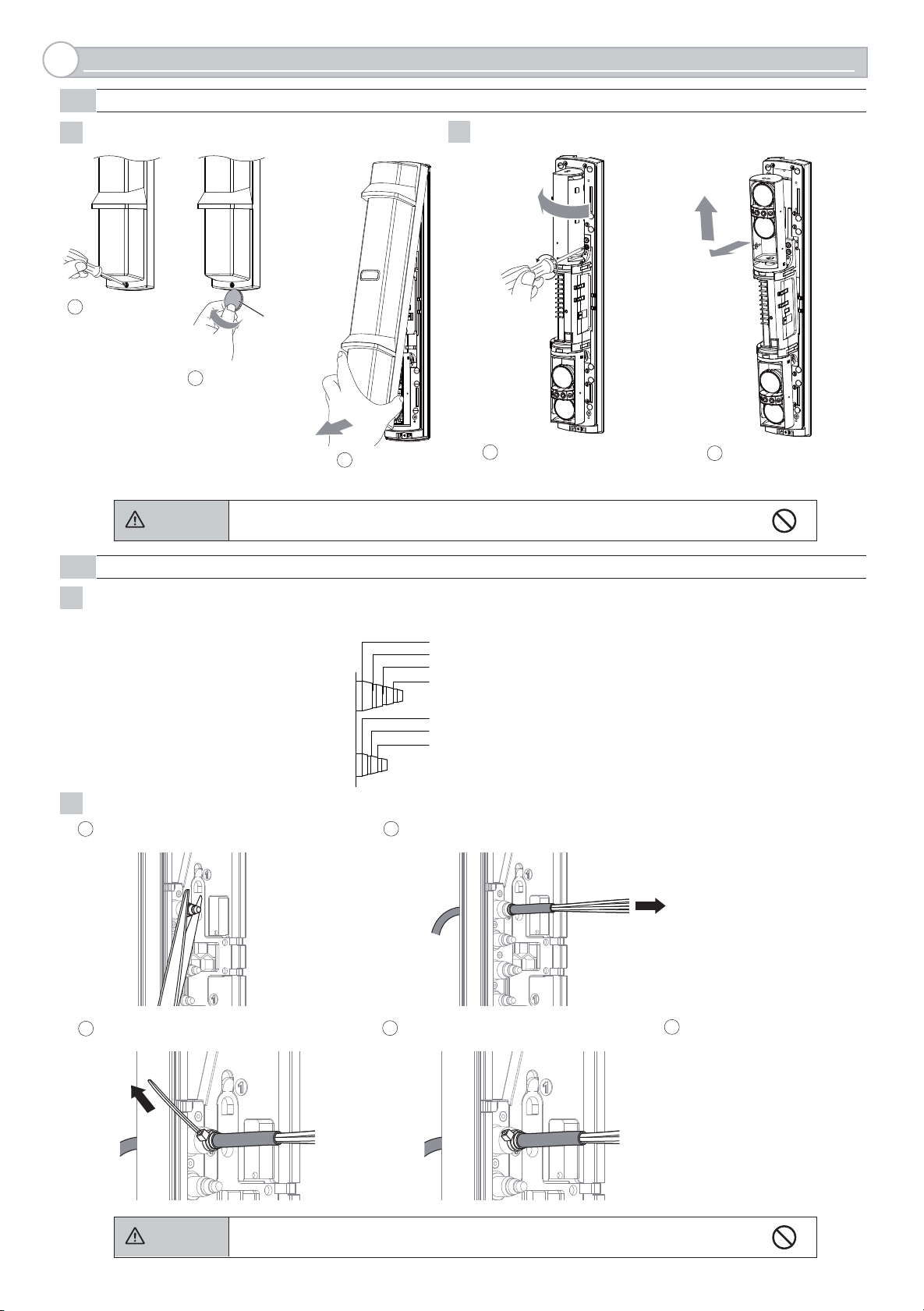
2-1
SEPARATING
Remove the cover.
1
1
Loosen the
cover lock screw.
2-2
WIRING
2
Caution
Remove the main unit from the chassis.
2
1
2
A coin
(Not included)
Twist it lightly.
1
3
Pull
Do not place the main unit where it allows to incident direct sunlight to its optical lens during
installation. Doing so may cause damage to the product.
Turn the optical unit 90 degrees
and loosen the screws (both
sides).
4
3
Pull the upper part of
2
main unit, and raise it to
remove.
Preparing the cut bush
1
Cut the wiring grommet required according to the wire diameter. Use the lidded grommet for the wiring hole not to be used.
(I.D. : Inter diameter)
Threading the wire
2
1
Cut off the cut bush according to the cable size.
3
I.D. 10mm (0.39 inch)
I.D. 8mm (0.31 inch)
I.D.
6mm (0.24 inch)
I.D. 4mm (0.16 inch)
I.D. 7mm (0.28 inch)
I.D. 6mm (0.24 inch)
I.D. 4mm (0.16 inch)
2
Pass the cable through the cut bush.
4
5
Connect to the terminalsCut the excess portion of the banding band.Tighten the cable with the banding band.
Refer to "TERMINAL" on Page
4 to make connections to the
terminals and refer to “OPTICAL ALIGNMENT” on Page 8
to make alignment for the
maximum level of light
reception.
Caution
Do not exceed the voltage or current rating specified for any of the terminals during
installation, doing so may cause fire or damage to the product.
-3-
Page 4
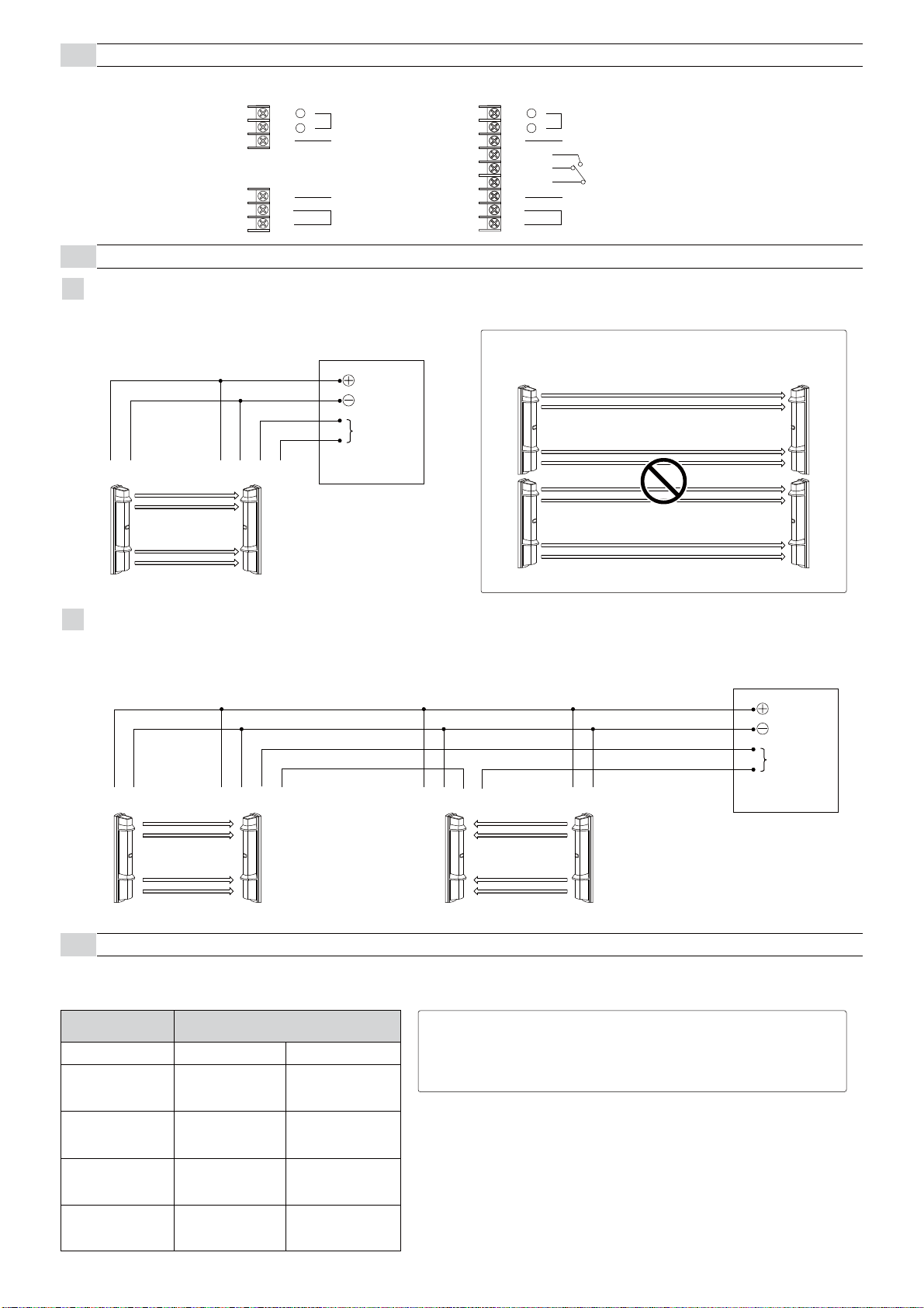
2-3
TERMINAL
WIRING DIAGRAM
2-4
1
1 Set
Connect the power supplies in parallel.
(1) (1)(2) (2) (5) (6)
<Transmitter>
(1) +
(2)
-
(3)
(7)
(8)
(9)
POWER INPUT
10.5-30VDC
SPARE
SPARE
TAMPER OUTPUT (N.C.)
CONTROL PANEL
POWER
ALARM
N.C.
<Receiver>
(1) +
(2)
(3)
(4) N.O.
(5) N.C.
(6) COM.
(7)
(8)
(9)
POWER INPUT
10.5-30VDC
SPARE
ALARM OUTPUT
SPARE
TAMPER OUTPUT (N.C.)
Note>>
2 Sets stacking installation is not available.
Transmitter Receiver
2
2 Sets in the line
Connect the power supply in parallel. Connect the units serially for a normally closed alarm output and in parallel for a normally open output
(the figure below shows an example for a normally closed alarm output).
(1) (1)(2) (2) (1) (2)(5) (6) (1) (2) (5) (6)
2-5
WIRING DISTANCE BETWEEN POWER SUPPLY AND DETECTOR
Transmitter Receiver
CONTROL PANEL
POWER
ALARM
N.C.
TransmitterReceiverTransmitter Receiver
- Ensure that the wiring distance from the power supply is within the range shown in the table below.
-
When using two or more units on one wire, the maximum length is obtained by dividing the wire length listed below by the number of units used.
MODEL
WIRE SIZE
0.33mm
(AWG22)
0.52mm
(AWG20)
0.83mm
(AWG18)
1.31mm
(AWG16)
SL-200/350/650QN
12VDC 24VDC
2
2
2
2
400m
(1300ft)
600m
(2000ft)
1000m
(3300ft)
1500m
(5000ft)
2300m
(7300ft)
3600m
(12000ft)
5800m
(19000ft)
9200m
(30000ft)
Note>>
UL requires to be connected to a UL listed power supply capable of providing a
norminal input of 12 VDC, (10.5 - 30 VDC) 45 mA and battery stand by time of 4
hours
-4-
Page 5

2-6
WALL MOUNTING
Open the wiring guide on the back of the chassis using
1
pliers as shown.
[ Upper ] [ Lower ]
Mount the chassis to the wall.
3
Side wall
Pull the waterproof packing (x2) marked as "①" at the center of
2
the chassis.
Put the waterproof packing back in place.
4
Distance from the side wall:
at least 1m
4×20 self tapping
(with rubber washer)
Fix the main unit.
5
1
Insert the lower part, and then push the upper part
onto the chassis.
Turn the optical unit 90 degrees and tighten the screws (both sides).
2
1
2
-5-
Page 6

Mount the cover and check the operation.
6
Hook on the upper part of
1
the chassis.
2
Push the lower part of the
cover until it clicks into
position.
Note>>
Push the middle part of the cover and hide this
orange label completely when in operation.
Orange label
3
Fasten the cover
lock screw.
Make function settings and optical alignment before mounting the cover.
Caution
2-7
POLE MOUNTING
Do not contact with the optical unit when mounting the cover. Otherwise malfunction
may occur due to the shift of the optical axis, resulting in the need of readjustment.
< Installing one detector >
Using a screwdriver or similar tool, break the knockout position (x4) in the chassis as shown.
1
Note>>
• When mounting the single set of detectors to the pole, use
a pair of the inside knockouts.
The knockout positions are marked "②" as shown.
If you accidentally open an unnecessary knockout, be
sure to fill the knockout. Not doing so may result in
waterproof failure and malfunction of the product.
A cover must hide this orange label completely when in operation.
Knockout position
Caution
Fix the chassis on the pole.
2
Side wall
Distance from the side wall:
at least 1m
M4×30 screw
(with rubber washer)
Perform the wall mounting procedure of 4 to 5 on page 5.
3
Make function settings and optical alignment before mounting the cover.
Note>>
• Before fixing the chassis on the pole, temporarily fix one
point at the center of the pole mounting bracket to the
back of the chassis.
3×6 self tapping
-6-
Page 7

< Installing two detectors in opposing directions >
Using a screwdriver or similar tool, break the knockout position
1
(x4) in the chassis as shown.
Inside pair of
knockouts
marked
"②"
Outside pair of
knockouts
marked
Note>>
• Choose a different pair of knockouts.
Pairs of the knockout positions are marked "②" and "③".
Perform the wall mounting procedure of 4 to 5 on page 5.
3
"③"
Fix the chassis on the pole.
2
3×6 self tapping
M4×30 screw
(with rubber washer)
Note>>
• Before fixing the chassis on the pole, temporarily fix one point
at the center of the pole mounting bracket to the back of the
chassis. Refer to procedure 2 of “Installing one detector”.
Make function settings and optical alignment before mounting the cover.
2-8
MOUNTING IN THE BEAM TOWER
In accordance with the type of the main unit inside the beam tower, install the detector in the same way as wall mounting or pole mounting.
1
< Mounting with the chassis > < Mounting without the chassis >
Make function settings and optical alignment before mounting the cover.
2-9
INSTALLATION EXAMPLE AT PARTICULAR CASE
Avoid installing the transmitter and receiver facing each other
1
through the corner of the cover.
[ Top view ]
Transmitter Receiver
-7-
In doing this installation, the maximum detection range shall be
2
half of the original detection range.
(This is to compensate the attenuation of beam by the corner
of the cover.)
ex) SL-200QN 60m/200ft.30m/100ft.
Page 8

FUNCTION SETTING
3
3-1
BEAM INTERRUPTION ADJUSTMENT
Initial setting is at 50 msec for normal work. According to the speed of a supposed target you select one specific setting out of 4 steps.
Set the beam interruption adjustment switches of the Receiver according to the speed of the human object to detect.
ON
Dip switch
(Receiver)
1 2
Running Jogging Walking Slow movement
Typical
interruption
time setting
OPTICAL ALIGNMENT
4
4-1
OPTICAL ALIGNMENT FOR UPPER AND LOWER BEAM
Optical alignment is an important adjustment to increase
reliability. Be sure to take adjustment steps 1 through 5
described below to attain the maximum level of the output
through the monitor jack.
Perform rough alignment of the horizontal angle.
1
(50 msec) (100 msec) (250 msec) (500 msec)
ON
1 2
< Horizontal alignment angle > < Vertical alignment angle >
[ TOP VIEW ]
90°
ON
1 2
90°
ON
1 2
[ SIDE VIEW ]
10°
10°
10°
10°
Note>>
• Mount a beam blocking plate to the
Hold and move the lens
to the left or the right.
Beam blocking plate
Look into the view finder and perform fine alignment of the horizontal and vertical angles using the alignment dial.
2
lower unit and then start optical
alignment from the upper unit.
• Beam blocking plate is attached on
the back of the cover.
• Put back the beam blocking plate to
the cover after use.
Beam blocking plate
Note>>
View finder
< How to look into the view finder >
From right side From left side
Cover
-8-
Left eye Right eye
Page 9

Note>>
Check the diagram below and perform fine alignment
for both horizontal alignment and vertical alignment.
Turn the small dial for
horizontal alignment.
Turn the large dial for
vertical alignment.
- Clockwise: Upward
- Counterclockwise: Downward
After the alignment using the viewfinder, make adjustment with the voltmeter for more accurate optical alignment.
3
Set the voltmeter range to 5 to 10 VDC.
After checking the receiving level of optical axis by using the alarm indicator, make sure to make fine alignment for both transmitter
and receiver with voltmeter to achieve a monitor output level of "Excellent" or "Good".
Do not look at strong light sources such as
sunlight through the view finder.
Do not touch the lens during optical alignment.
Warning
Caution
Insert the voltmeter's positive pin
into the positive terminal of the
monitor jack, and the negative pin
into the negative terminal.
Adjust the horizontal and vertical angles while checking the light receiving status by Alarm indicator LED on the pairing receiver.
4
Receiver
Alarm indicator
Indicator LED
Caution
Make the settings of 1 to 4 to the lower as well.
5
OPERATION CHECK
5
Conduct a walk to check that the alarm indicator LED on the receiver turns ON as the walker interrupts the beam.
Be sure to conduct a walk test (to block the infrared beam) at the following three points:
A
In front of the transmitter
B
In front of the receiver
C
At the middle point between the transmitter and the receiver
Be sure to perform fine alignment to ensure the maximum output level through the monitor
jack.
Alarm
LED
Adjustment
level
Monitor jack
output
Light
interrupted
ON (Red) OFF
Realign Fair Good
0 V 2.0 V 3.5 V 5.0 V
Light received
Note>>
Conduct a walk test at least once a year.
Excellent
The detector is installed properly when the alarm indicator LED turns ON
in the tests at all three poinrs.
-9-
Transmitter
Receiver
A
C
B
Page 10

OPTION SETTING
6
6-1
HEATER UNIT HU-3 (OPTION)
The heat release effect makes the unit less prone to frost. HU-3 can be mounted to either upper or lower part of the unit.
Use a 24 V power supply to use HU-3.
< Mounting method >
Tear the wiring groove section of the label that is pasted on
1
the chassis as shown below.
Insert HU-3 into the chassis.
2
NOTE>>
NOTE>>
The label can be torn with a
finger.
• Insert the tip of HU-3
into the hook of the
chassis to mount HU-3.
• Do not mount HU-3 with
the face down.
Caution
Do not wire HU-3 to
the main unit. Doing
so may result in
malfunction.
Route the cable alng the wiring groove and draw the cable
3
through the cutbush.
DIMENSIONS
7
When connecting the lead wires to the wiring, make the
4
connection using the included connector or soldering. Insert
the wires into the connector and tighten the connections with
pliers.
Connector
NOTE>>
Ensure that the wiring distance from the power supply is within
the range shown in the table on the right. When using 2 or
more units on 1 wire, the maximum wiring distance is obtained
by dividing the wire distance by the number of unit used.
0.83 mm2 (AWG18)
2
1.31 m m
(AWG16)
2
(AWG14)
2.09 mm
79 (3.1)
300 m (1000 f t.)
500 m (1700 ft.)
800 m (2600 ft.)
448 (17.6)
96 (3.8)
-10-
(WALL)
84 (3.3)
222 (8.7) (POLE1)
265 (10.4) (POLE2)
Unit: mm (inch)
Page 11

TROUBLESHOOTING
8
PROBLEM POSSIBLE CAUSE CORRECTIVE ACTION
Indicator LED is not illuminated.
Transmitter : During normal operation
Receiver : Light interrupted
Inappropriate power voltage
Inappropriate wiring distance or wire diameter
Check the voltage and make sure that it is
between 10.5 and 30 VDC.
See "2-5 WIRING DISTANCE BETWEEN POWER
SUPPLY AND DETECTOR" on page 4,check the
wiring distance.
"ALARM" indicator LED is not
illuminated even if the beam is
blocked.
Blocking the beam, and
illuminates "ALARM" indicator LED
but does not active the alarm.
Alarm is activated even if the light
is not blocked.
Frost, snow or heavy rain causes
false alarm.
Improper output
SPECIFICATIONS
9
< SL-200QN, SL-350QN, SL-650QN >
Model
Maximum detection range
Maximum arrival distance
Detection method
Interruption time
Power source
Reection of the oor or wall
Beam has not been blocked.
Signal line short-circuited
Alarm contact welded
Interruption time is too short.
Surface of Transmitter/Receiver cover soiled.
Optical alignment was not performed properly.
Optical alignment is not optimazed.
The wiring is incorrected.
SL-200QN SL-650QNSL-350QN
60 m/200ft 100 m/350 ft 200 m/650 ft
600 m/2000ft 1000 m/3500 ft 2000 m/6500 ft
Quad infrared beam interruption detection
Variable between 50/100/250/500 ms
(4 steps)
10.5 - 30 VDC
See"4-1 OPTICAL ALIGNMENT" on Page 8 and
make realignment.
Block all four beams at same time.
Check the wiring.
Repair is required. Contact the distributor or us.
See "3-1 BEAM INTERRUPTION ADJUSTMENT"
on page 8, set an appropriate interruption time.
Clean the cover (wipe the cover with a soft cloth
dampened with water od diluted neutral detergent).
See"4-1 OPTICAL ALIGNMENT" on Page 8 and
make realignment.
See"4-1 OPTICAL ALIGNMENT" on Page 8 and
make realignment.
Make correct wiring.
Current draw
Alarm output
Output
Operating temperature
Operating humidity
Alignment angle
Dimension
Weight
International protection IP65
Alarm period 2 sec (±1) (Nominal)
Tamper output
(Transmitter: 8 mA Receiver: 30 mA)
38 mA
(Transmitter: 9 mA Receiver: 30 mA)
Form C relay: 30 VDC, 0.2 A
N.C. (contact output): 30 VDC, 0.1 A Opens when cover removed.
-25°C - +60°C (-13°F - 140°F)
±90° Horizontal, ±10° Vertical
H W D mm (inch): 448 (17.6) x 79 (3.1) x 96 (3.8)
2400 g (84.7oz) (Total weight of Transmitter + Receiver, excluding accessories)
39 mA
95 % (max.)
< HU-3 (Option) >
Model HU-3
Power input
Current draw
Thermo switch
Operating temperature
Weight
Packages
-35°C - +60°C(-31°F - +140°F)
Heater(x2), Connector(x4), Waterproof agent
24VAC/DC
420mA(max.) (Per 1 unit)
140
60°C (
20g(0.7oz) (Heater(x2))
°F)
(Transmitter: 10 mA Receiver: 30 mA)
40 mA
NOTE
These units are designed to detect an intruder and
activate an alarm control panel. Being only a part of a
complete system, we cannot accept responsibility for
any damages or other consequences resulting from an
intrusion.
These products conform to the EMC Directive
2004/108/EC.
-11-
Page 12

10
OPTIONS
Anti Bird Cap ABC-4
Prevent birds and small animals from the detector to reduce the
false alarm.
Prevent streaming rain and snow from the front of the detector to
keep the sensitivity.
84 (3.3)
468 (18.4)
96 (3.8)
Unit: mm (inch)
Back Cover BC-4
Conceal the back side of pole mounted detector.
Pole Side Cover PSC-4
Conceal the gap of pole mounted detectors back to back.
458 (18)
85 (3.3)
226〜241 (8.9〜9.5)
Unit: mm (inch)
Beam Alignment Unit BAU-4
Adjust optical axis automatically. (Receiver only)
448 (18)
79 (3.1)
Conduit Bracket CBR-4
This allows for conduit wiring.
452 (17.8)
83 (3.3) 138 (5.4)
154 (6.1)
Unit: mm (inch)
Unit: mm (inch)
Heater Unit HU-3
0.6 (0.02)
97 (3.8)
28 (1.1)
Actual length 200 (7.9)
Unit: mm (inch)
OPTEX CO., LTD. (JAPAN)
(ISO 9001 Certified)
(ISO 14001 Certified)
5-8-12 Ogoto Otsu
Shiga 520-0101
JAPAN
TEL:+81-77-579-8670
FAX:+81-77-579-8190
URL:http://www.optex.co.jp/e/
OPTEX INCORPORATED (USA)
TEL:+1-909-993-5770
Tech:(800)966-7839
URL:http://www.optexamerica.com/
OPTEX (EUROPE) LTD. (UK)
TEL:+44-1628-631000
URL:http://www.optex-europe.com/
OPTEX SECURITY SAS (FRANCE)
TEL:+33-437-55-50-50
URL:http://www.optex-security.com/
-12-
OPTEX SECURITY Sp.z o.o. (POLAND)
TEL:+48-22-598-06-55
URL:http://www.optex.com.pl/
OPTEX KOREA CO., LTD. (KOREA)
TEL:+82-2-719-5971
URL:http://www.optexkorea.com/
OPTEX (DONGGUAN) CO., LTD.
SHANGHAI OFFICE (CHINA)
TEL:+86-21-34600673
URL:http://www.optexchina.com/
 Loading...