


No. 59-1882-0
INSTALLATION INSTRUCTIONS
PHOTOELECTRIC DETECTOR
 Smart Line™series
Model |
Detection range |
SL-200QN |
60m/200ft. |
SL-350QN |
100m/350ft. |
SL-650QN |
200m/650ft. |
|
|
FEATURES
•Quad high power beams
•Smart design
-Slim body design
-Easy-to-see vivid interior color for optical alignment
-IP65 waterproof structure
•View finder with 2X magnification
•Various options (refer to page 12)
( HU-3, ABC-4, BC-4, CBR-4, PSC-4, BAU-4 )
•Beam interruption adjustment function
•Tamper function
CONTENTS
1 INTRODUCTION |
|
3 |
2-8 MOUNTING IN THE BEAM TOWER.............. |
7 |
1-1 BEFORE YOUR OPERATION ....................... |
1 |
FUNCTION SETTING |
|
|
1-2 PRECAUTIONS....................................................... |
2 |
4 |
3-1 BEAM INTERRUPTION ADJUSTMENT........ |
8 |
1-3 PARTS IDENTIFICATION..................................... |
2 |
OPTICAL ALIGNMENT |
|
|
2 INSTALLATION |
|
|
4-1 OPTICAL ALIGNMENT FOR UPPER AND |
|
2-1 SEPARATING................................................. |
3 |
|
LOWER BEAM............................................... |
8 |
2-2 WIRING.......................................................... |
3 |
5 |
OPERATION CHECK........................................... |
9 |
2-3 TERMINAL ..................................................... |
4 |
6 |
OPTIONAL SETTING |
|
2-4 WIRING DIAGRAM ........................................ |
4 |
7 |
6-1 HEATER UNIT HU-3 (OPTION) .................... |
10 |
2-5 WIRING DISTANCE BETWEEN POWER |
|
DIMENSIONS...................................................... |
10 |
|
SUPPLY AND DETECTOR ............................ |
4 |
8 |
TROUBLESHOOTING ........................................ |
11 |
2-6 WALL MOUNTING ......................................... |
5 |
9 |
SPECIFICATIONS............................................... |
11 |
2-7 POLE MOUNTING ......................................... |
6 |
10 |
OPTIONS ............................................................ |
12 |
1 INTRODUCTION
1-1 BEFORE YOUR OPERATION
•Read this instruction manual carefully prior to installation.
•After reading, store this manual carefully in an easily accessible place for reference.
•This manual uses the following warning indications for correct use of the product, harm to you or other people and damage to your assets, which are described below. Be sure to understand the description before reading the rest of this manual.
Warning |
Failure to follow the instructions provided with this indication and improper handling may cause |
|
death or serious injury. |
||
Caution |
Failure to follow the instructions provided with this indication and improper handling may cause |
|
injury and/or property damage. |
||
|
||
|
|
This symbol indicates prohibition. The specific prohibited action is provided in and/or around the figure.
This symbol requires an action or gives an instruction.
Do not use the product for purposes other than the detection of moving objects such as people and vehicles. Do not use the product to activate a shutter, etc., which may cause an accident.
|
Do not touch the unit base or power terminals of the product with a wet hand (do not |
Warning |
touch when the product is wet with rain, etc.). It may cause electric shock. |
|
Never attempt to disassemble or repair the product. It may cause fire or damage to the devices.
Do not exceed the voltage or current rating specified for any of the terminals during installation, doing so may cause fire or damage to the devices.
Do not pour water over the product with a bucket, hose, etc. The water may enter, which may cause damage to the devices.
Caution |
Clean and check the product periodically for safe use. If any problem is found, do not |
|
attempt to use the product as it is and have the product repaired by a professional |
|
engineer or electrician. |
-1-

1-2 PRECAUTIONS
Do not install the unit on an unstable surface.
Do not install the pole in a |
Do not install the unit in a |
Do not install the receiver in a |
location where sufficient |
location where trees, leaves, or |
location where it is exposed to |
stability can not be ensured. |
other objects that may swing in |
direct sunlight. |
|
the wind and block the beam. |
|
[Receiver]
Do not allow the infrared beam from another detector to reach the receiver.
Receiver |
Transmitter |
Receiver |
Transmitter |
(another |
(another |
detector) |
detector) |
Install the unit at a height |
|
|
The pole size should be |
||||||
where an object can be |
|
|
34 - 48 mm |
||||||
detected without fail. |
|
|
( 1.34 - 1.89 inch). |
||||||
|
|
|
|
|
|
|
|
|
|
|
|
|
|
|
|
|
|
|
|
|
|
|
|
|
|
|
|
|
|
|
|
|
|
|
|
|
|
|
|
|
|
|
|
|
|
|
|
|
|
|
|
|
|
|
|
|
|
|
|
|
|
|
|
|
|
|
|
|
|
Transmitter Receiver
This symbol indicates prohibition.
Install the unit at least 1 m (3.3 ft.) away from the wall or fence that may be running parallel to the beam.
At least 1 m (3.3 ft.)
This symbol indicates recommendation.
1-3 PARTS IDENTIFICATION
Cover |
Main unit |
Chassis |
Optical lens |
View finder |
Pole mounting |
|
|
screw holes |
|
Main unit base |
|
Horizontal alignment dial |
Mounting screw holes |
|
|
|
|
Vertical alignment dial |
Cut bush |
Wall mounting |
|
for wiring |
screw holes |
Terminals |
|
|
|
|
|
Pole mounting |
|
Vertical alignment dial |
Tamper button |
screw holes |
|
|
||
|
|
|
|
Beam blocking plate |
Horizontal alignment dial |
|
|
|
Optical lens |
|
|
|
Cover lock screw |
View finder |
|
FUNCTION SETTING SECTION >> |
ACCESSORIES >> |
<Transmitter> |
<Receiver> |
T |
R |
|
Monitor jack (+) |
|
Monitor jack (-) |
Power indicator |
Alarm indicator |
|
Dip switch |
3×6 self tapping for pole bracket: 4
Banding bands: 4 |
U-brackets: 4 |
4×20 self tapping for wall mounting (with rubber washer): 4
Pole brackets: 4
M4×30 screws for pole mounting
(with rubber washer): 8 Beam blocking plate: 2 (attached on the back of the cover)
-2-
2 INSTALLATION
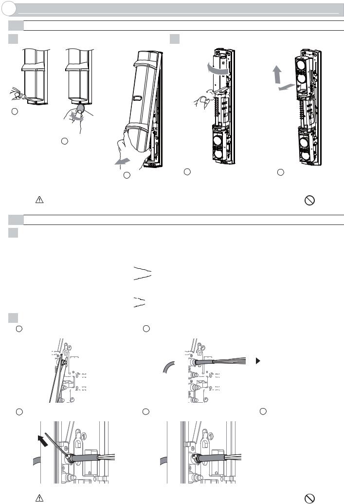
2-1 SEPARATING
1 Remove the cover. |
2 Remove the main unit from the chassis. |
|
|
1 |
4 |
2 


 3
3
1 Loosen the |
|
cover lock screw. |
A coin |
|
(Not included) |
2 |
Twist it lightly. |
3 Pull
1 Turn the optical unit 90 degrees and loosen the screws (both sides).
2Pull the upper part of main unit, and raise it to remove.
Caution |
Do not place the main unit where it allows to incident direct sunlight to its optical lens during |
|
installation. Doing so may cause damage to the product. |
||
|
||
|
|
2-2 WIRING
1Preparing the cut bush
Cut the wiring grommet required according to the wire diameter. Use the lidded grommet for the wiring hole not to be used.
(I.D. : Inter diameter) |
|
|
|
|
|
|
|
|
I.D. 10mm (0.39 inch) |
|||
|
|
|
|
|
|
|
|
|
||||
|
|
|
|
|
|
|
|
|
|
|
I.D. |
8mm (0.31 inch) |
|
|
|
|
|
|
|
|
|
|
|
||
|
|
|
|
|
|
|
|
|
|
|
I.D. |
6mm (0.24 inch) |
|
|
|
|
|
|
|
|
|
|
|
I.D. |
4mm (0.16 inch) |
|
|
|
|
|
|
|
|
|
|
|
I.D. |
7mm (0.28 inch) |
|
|
|
|
|
|
|
|
|
|
|
||
|
|
|
|
|
|
|
|
|
|
|
||
|
|
|
|
|
|
|
|
|
|
|
||
|
|
|
|
|
|
|
|
|
|
|
I.D. |
6mm (0.24 inch) |
|
|
|
|
|
|
|
|
|
|
|
||
|
|
|
|
|
|
|
|
|
|
|
I.D. |
4mm (0.16 inch) |
|
|
|
|
|
|
|
|
|
|
|
|
|
|
|
|
|
|
|
|
|
|
|
|
|
|
2Threading the wire
1 Cut off the cut bush according to the cable size. |
2 Pass the cable through the cut bush. |
|
|||||||||||||||||||||||||||||||||||||||||||||
|
|
|
|
|
|
|
|
|
|
|
|
|
|
|
|
|
|
|
|
|
|
|
|
|
|
|
|
|
|
|
|
|
|
|
|
|
|
|
|
|
|
|
|
|
|
|
|
|
|
|
|
|
|
|
|
|
|
|
|
|
|
|
|
|
|
|
|
|
|
|
|
|
|
|
|
|
|
|
|
|
|
|
|
|
|
|
|
|
|
|
|
|
|
|
|
|
|
|
|
|
|
|
|
|
|
|
|
|
|
|
|
|
|
|
|
|
|
|
|
|
|
|
|
|
|
|
|
|
|
|
|
|
|
|
|
|
|
|
|
|
|
|
|
|
|
|
|
|
|
|
|
|
|
|
|
|
|
|
|
|
|
|
|
|
|
|
|
|
|
|
|
|
|
|
|
|
|
|
|
|
|
|
|
|
|
|
|
|
|
|
|
|
|
|
|
|
|
|
|
|
|
|
|
|
|
|
|
|
|
|
|
|
|
|
|
|
|
|
|
|
|
|
|
|
|
|
|
|
|
|
|
|
|
|
|
|
|
|
|
|
|
|
|
|
|
|
|
|
|
|
|
|
|
|
|
|
|
|
|
|
|
|
|
|
|
|
|
|
|
|
|
|
|
|
|
|
|
|
|
|
|
|
|
|
|
|
|
|
|
|
|
|
|
|
|
|
|
|
|
|
|
|
|
|
|
|
|
|
|
|
|
|
|
|
|
|
|
|
|
|
|
|
|
|
|
|
|
|
|
|
|
|
|
|
|
|
|
|
|
|
|
|
|
|
|
|
|
|
|
|
|
|
|
|
|
|
|
|
|
|
|
|
|
|
|
|
|
|
|
|
|
|
|
|
|
|
|
|
|
|
|
|
|
|
|
|
|
|
|
|
|
|
|
|
|
|
|
|
|
|
|
|
|
|
|
|
|
|
|
|
|
|
|
|
|
|
|
|
|
|
|
|
|
|
|
|
|
|
|
|
|
|
|
|
|
|
|
|
|
|
|
|
|
|
|
|
|
|
|
|
|
|
|
|
|
|
|
|
|
|
|
|
|
|
|
|
|
|
|
|
|
|
|
|
|
|
|
|
|
|
|
|
|
|
|
|
|
|
|
|
|
|
|
|
|
|
|
|
|
|
|
|
|
|
|
|
|
|
|
|
|
|
|
|
|
|
|
|
|
|
|
|
|
|
|
|
|
3 Tighten the cable with the banding band. |
4 Cut the excess portion of the banding band. |
5 Connect to the terminals |
Refer to "TERMINAL" on Page 4 to make connections to the terminals and refer to “OPTI-
CAL ALIGNMENT” on Page 8 to make alignment for the maximum level of light reception.
Caution |
Do not exceed the voltage or current rating specified for any of the terminals during |
|
installation, doing so may cause fire or damage to the product. |
||
|
||
|
|
-3-
2-3 TERMINAL
<Transmitter> |
|
<Receiver> |
|
||
(1) |
+ |
POWER INPUT |
(1) |
+ |
POWER INPUT |
(2) |
- |
10.5-30VDC |
(2) |
- |
10.5-30VDC |
(3) |
|
SPARE |
(3) |
|
SPARE |
|
|
|
(4) |
N.O. |
ALARM OUTPUT |
|
|
|
(5) N.C. |
||
(7) |
|
|
(6) |
COM. |
|
|
SPARE |
(7) |
|
SPARE |
|
(8) |
|
TAMPER OUTPUT (N.C.) |
(8) |
|
TAMPER OUTPUT (N.C.) |
(9) |
|
(9) |
|
||
|
|
|
|
||
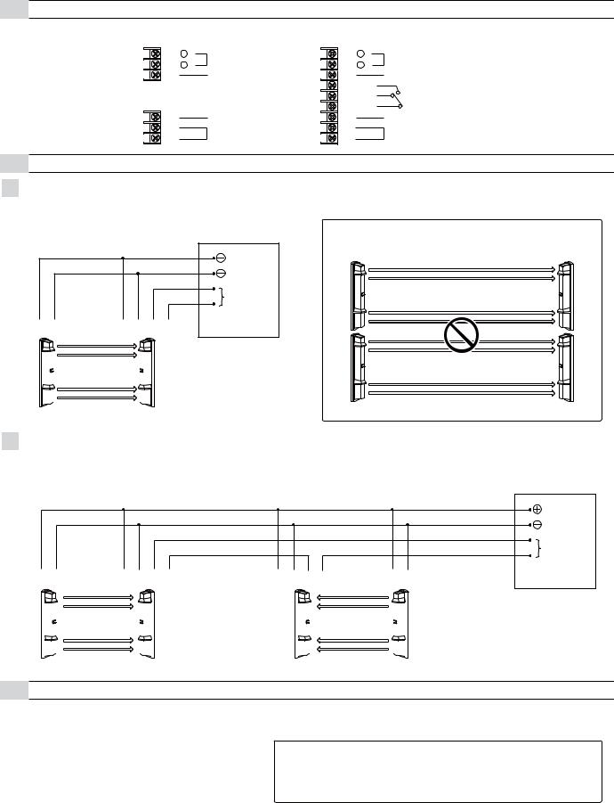
2-4 WIRING DIAGRAM
11 Set
Connect the power supplies in parallel.
CONTROL PANEL |
Note>> |
|
2 Sets stacking installation is not available. |
POWER |
|
ALARM |
|
N.C. |
|
(1) |
(2) |
(1) |
(2) |
(5) |
(6) |
|||||
|
|
|
|
|
|
|
|
|
|
|
|
|
|
|
|
|
|
|
|
|
|
|
|
|
|
|
|
|
|
|
|
|
|
|
|
|
|
|
|
|
|
|
|
|
|
|
|
|
|
|
|
|
|
|
|
|
|
|
|
|
|
|
|
|
|
|
|
|
|
|
|
|
|
|
|
|
|
|
|
|
|
|
|
|
|
|
|
|
|
|
|
|
|
|
|
|
|
|
Transmitter |
Transmitter |
Receiver |
Receiver |
|
22 Sets in the line
Connect the power supply in parallel. Connect the units serially for a normally closed alarm output and in parallel for a normally open output (the figure below shows an example for a normally closed alarm output).
CONTROL PANEL
POWER
ALARM
N.C.
(1) |
(2) |
(1) |
(2) |
(5) |
(6) |
(1) |
(2) |
(5) |
(6) |
(1) |
(2) |
||||||||||
|
|
|
|
|
|
|
|
|
|
|
|
|
|
|
|
|
|
|
|
|
|
|
|
|
|
|
|
|
|
|
|
|
|
|
|
|
|
|
|
|
|
|
|
|
|
|
|
|
|
|
|
|
|
|
|
|
|
|
|
|
|
|
|
|
|
|
|
|
|
|
|
|
|
|
|
|
|
|
|
|
|
|
|
|
|
|
|
|
|
|
|
|
|
|
|
|
|
|
|
|
|
|
|
|
|
|
|
|
|
|
|
|
|
|
|
|
|
|
|
|
|
|
|
|
|
|
|
|
|
|
|
|
|
|
|
|
|
|
|
|
|
|
|
|
|
|
|
|
|
|
|
|
|
|
|
|
|
|
|
|
|
|
|
|
|
|
|
|
|
|
|
|
|
|
|
|
|
|
|
|
|
|
|
|
|
|
|
|
|
|
|
|
|
|
|
|
|
|
|
|
|
|
|
|
|
|
|
|
|
|
|
|
|
|
|
|
|
|
|
Transmitter |
Receiver |
Receiver |
Transmitter |
2-5 WIRING DISTANCE BETWEEN POWER SUPPLY AND DETECTOR
-Ensure that the wiring distance from the power supply is within the range shown in the table below.
-When using two or more units on one wire, the maximum length is obtained by dividing the wire length listed below by the number of units used.
MODEL |
SL-200/350/650QN |
|
|
|
|
WIRE SIZE |
12VDC |
24VDC |
0.33mm2 |
400m |
2300m |
(AWG22) |
(1300ft) |
(7300ft) |
|
|
|
0.52mm2 |
600m |
3600m |
(AWG20) |
(2000ft) |
(12000ft) |
|
|
|
0.83mm2 |
1000m |
5800m |
(AWG18) |
(3300ft) |
(19000ft) |
|
|
|
1.31mm2 |
1500m |
9200m |
(AWG16) |
(5000ft) |
(30000ft) |
|
|
|
Note>>
UL requires to be connected to a UL listed power supply capable of providing a norminal input of 12 VDC, (10.5 - 30 VDC) 45 mA and battery stand by time of 4 hours
-4-
 Loading...