

Page 1
- 1 -
ENGLISH FRANÇAIS DEUTSCH ITALIANO ESPAÑOL
INTRODUCTION
1
1 INTRODUCTION
1-1
BEFORE OPERATION ............................................................. 1
1-2
PRECAUTIONS ........................................................................ 2
1-3
PARTS IDENTIFICATION ......................................................... 2
2 TYPES OF INSTALLATION METHOD AND DETECTION AREAS
2-1
TYPES OF INSTALLATION METHOD ..................................... 2
2-2
TYPES OF DETECTION METHOD .......................................... 3
2-3
AREA SETTING PROCEDURE ................................................ 3
3 INSTALLATION AND ANGLE ADJUSTMENT
3-1
INSTALLING TO WALL AND ANGLE ADJUSTMENT .............. 4
3-2
INSTALLING TO CEILING PLANE AND ANGLE
ADJUSTMENT .......................................................................... 5
3-3
INSTALLING TO POLE ............................................................. 6
3-4
INSTALLING AT AN ANGLE TO WALL OR CEILING
PLANE ...................................................................................... 6
3-5
INSTALLING AT AN ANGLE TO POLE ..................................... 7
4 PARTS LAYOUT INSIDE THE COVER AND THEIR FUNCTIONS
4-1
WIRING ..................................................................................... 7
4-2
RESET SWITCH ....................................................................... 7
4-3
SIGNAL OUTPUT ..................................................................... 7
4-4
CONNECTING WALK TESTER ................................................ 8
4-5
POWERING ON ........................................................................ 8
4-6
SWITCH LAYOUT ..................................................................... 8
4-7
LED FUNCTIONS ..................................................................... 8
5 SETTING HORIZONTAL DETECTION AREAS 1 AND 2
5-1
SELECTOR SWITCH OPERATION ......................................... 8
5-2
MANUAL SETTING OF HORIZONTAL DETECTION
AREA ........................................................................................ 9
5-3
STARTING SECURITY PROTECTION IN MANUAL
MODE ....................................................................................... 9
5-4
AUTO SETTING OF HORIZONTAL DETECTION AREA ......... 9
6 SETTING VERTICAL DETECTION AREA
6-1
SELECTOR SWITCH OPERATION ....................................... 10
6-2
SETTING DETECTION AREA IN VERTICAL
DETECTION AREA .................................................................
10
6-3
AUTO SETTING OF VERTICAL DETECTION AREA ..............11
7 AREA CHECKUPS
7-1
WALK TEST .............................................................................11
7-2
CHANGING THE SETTINGS DURING SECURITY
PROTECTION .........................................................................11
7-3
SYSTEM FUNCTION AFTER POWER FAILURE .................. 12
8 SPECIFICATIONS
8-1
SPECIFICATIONS OF THE MAIN UNIT ................................. 12
8-2
DIMENSIONAL DRAWING ..................................................... 12
8-3
OPTIONS ................................................................................ 12
1-1
BEFORE OPERATION
Read this instruction manual carefully prior to installation.
This manual uses the following warning indications to provide
information regarding correct usage of the product to prevent
you and other people from being harmed, and your assets
from being damaged. These warning indications are described
below.
Ensure you understand these precautions before reading the
rest of this manual.
Warning
Failure to follow the instructions provided by
this warning and improper handling may cause
death or serious injury.
Caution
Failure to follow the instructions provided by
this caution and improper handling may cause
injury and/or property damage.
This symbol indicates prohibition.
The specic prohibited action is provided in and/or around
the gure.
This symbol requires an action or gives an instruction.
Warning
Do not use the product for purposes other than the
detection of moving objects such as people and
vehicles.
Do not use the product to activate a shutter, etc.,
which may cause an accident.
Do not touch the unit base or power terminals of
the product with a wet hand (do not touch when the
product is wet with rain, etc.). It may cause electric
shock.
Never attempt to disassemble or repair the product. It
may cause re or damage to the devices.
Do not exceed the voltage or current rating specied
for any of the terminals, doing so may cause re or
damage to the devices.
Ensure the power is turned off before connecting
wiring.
Conrm the signal name of every terminal to ensure
wiring is carried out correctly.
Whenever a commercial switching regulator is used,
be sure to connect PE (Protective Earth Terminal).
Hold the main unit securely when you install or
service it. Exercise care not to bump the product
against nearby objects or drop it inadvertently.
This product is not capable of detecting objects in the
dead zone of the laser scan.
Do not use this product for an application where it is
not capable of covering the detection area required
by the task.
Please note that the product can malfunction,
including producing an irregular output and
committing a detection error, if it is exposed to
unfavorable environmental conditions such as
strong ambient light, electronic noises or mechanical
vibrations.
Caution
Use of controls or adjustments or performance of
procedures other than those specied herein may
result in hazardous radiation exposure.
Clean and check the product periodically for safe use.
If any problem is found, do not attempt to use the
product as it is.
When disposing of this product, be sure to follow the
waste-disposal regulations of the country or region
where it is used.
This product is intended to detect an intruder(s)
and is not designed to prevent theft, disasters or
accidents. The manufacturer shall not be held liable
for any damage to user’s property resulting from
theft, disasters or accidents.
•
•
FEATURES
* 30 m (Approx. 100 ft.) radius for 190 degrees
* Vertical and horizontal mounting
* Unique detection algorithm
* Four independently adjustable detection areas for PTZ camera
control
* Four independent N.O. outputs
* Form C master alarm outputs
* Automatic area setting function
* Environmental disqualification (EDQ) circuit
* Trouble output
* Tamper output
REDSCAN is an area sensor that configures a fan-like detection
area of 30 m (Approx.100 ft.) radius over 190 degrees arc. using
laser beams.
REDSCAN detects target objects by emitting laser beams at the
target and measuring the time required for the emitted beams to
be reflected and returned to the detector.
There are 3 modes for detecting an intruder. Horizontal Detection
Area1, Horizontal Detection Area2 and Vertical Detection Area.
Each one is configured with an independent detection algorithm.
CONTENTS
No.591555-0 2009.3
INSTALLATION INSTRUCTIONS
RLS-3060
RLS-3060
Laser Scan Detector
Laser Scan Detector
Page 2
- 2 -
- 3 -
TYPES OF INSTALLATION METHOD AND DETECTION AREAS
2
1-2
PRECAUTIONS
Install the product only on a
solid surface.
In the Horizontal Detection
Area, this product must
normally be used within the
recommended installation
height in order to detect an
intruder.
Install the product so that the
detection area is not inuenced
by interference from tall grass
or tree branches waving in the
wind.
Do not install or leave the
product in a location exposed
to heat, vibrations or impacts
beyond the noted rating.
Do not use the product in an
environment where solvent
fumes or corrosive gases are
present.
Do not use this product in
environments where there
may be oil mist particles which
may contaminate the window
of the detector; thus causing
detection errors and possible
corrosion which may lead to
product failure.
The symbol “Í” indicates prohibited actions.
Cleaning the Product
Clean the front window on a regular basis
using a wet cloth.
A smeared front window can limit the
detection area due to the reduced laser
sensitivity. In addition, heavy soiling of the
window can induce detection errors.
On Safety of Laser
This product is categorized as a Class 1 product in terms of the
Safety Standard.
Average Power : Max. 0.015 mW (AEL)
Wavelength : 905 nm
Pulse With : 4 ns
Emission period : 36 μs
Standard : IEC60825-1
Class 1 of the Laser Safety Standard means that the safety
of laser products belonging to this class is warranted under
normal operating conditions (reasonably predictable operating
conditions). The user is simply required to indicate that this
product is laser equipment. No additional safety measures are
necessary.
Certied to FDA (21 CFR part 1040.10 and 1040.11)
Class 1 laser product
Do not expose your eyes directly to the laser beam.
1-3
PARTS IDENTIFICATION
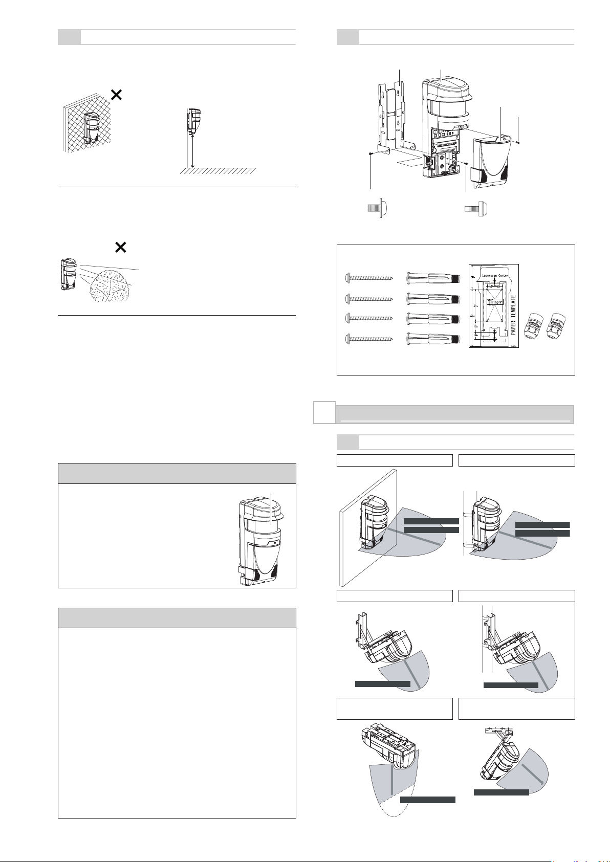
Accessories>>
2-1
TYPES OF INSTALLATION METHOD
Installing to a wall Installing to a pole
Installing at an angle to a wall Installing at an angle to a pole
Installing to a ceiling plane
Installing at an angle to a
ceiling plane
Installation height:
0.7 m to 1 m
(2.3 ft. to 3.3 ft.)
Front window
Mounting bracket Main unit
Cover
Cover mounting screw
Main unit mounting screw
Angle adjustment screw
4 screws
(For locking the
mounting bracket)
4 anchors
for the board
1 paper template 2 cable glands
Detection method
Detection method
Horizontal Detection Area 1
Horizontal Detection Area 2
Horizontal Detection Area 1
Horizontal Detection Area 2
Detection method
Detection method
Vertical Detection Area
Vertical Detection Area
Laser beam
Laser beam
Laser beam
Laser beam
Detection method
Detection method
Vertical Detection Area
Vertical Detection Area
Laser beam
Laser beam
Bracket is optional item.
Bracket is optional item. Bracket is optional item.
Bracket is
optional item.
Page 3
- 3 -
ENGLISH FRANÇAIS DEUTSCH ITALIANO ESPAÑOL
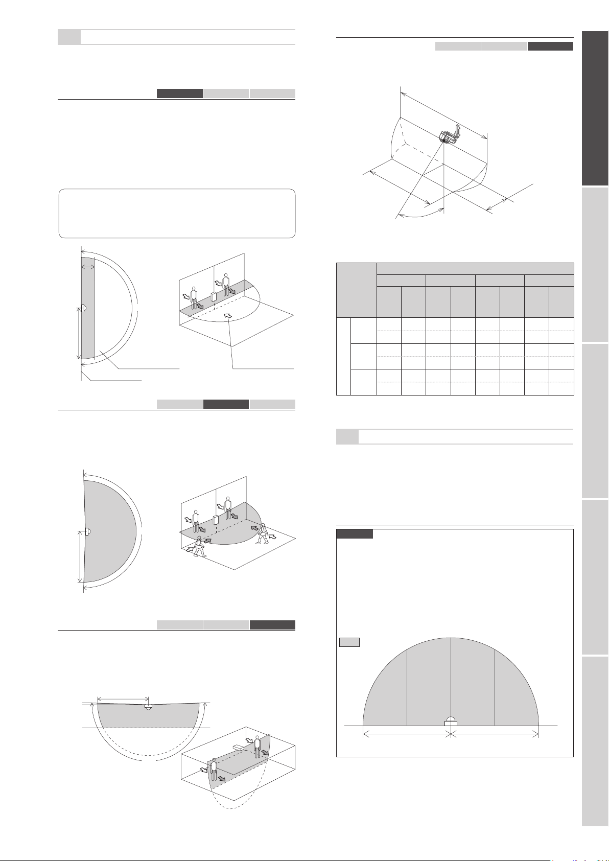
2-2
TYPES OF DETECTION METHOD
The detection method comprises the three modes of Horizontal
Detection Area 1, Horizontal Detection Area 2 and Vertical
Detection Area.
-Horizontal Detection Area 1
H1 H2 V
This mode allows setting of a fan-like detection area in
the horizontal direction with a maximum radius of 30 m
(Approx.100 ft.), a spread angle of 180 degrees, and a width of
1 m (3.3 ft.).
This mode detects intrusion of an object that appears from the
rear side of the sensor or in a position within 1 m (3.3 ft.) from
the sensor installation line and that moves toward the front of the
sensor.
Cautions>>
This mode does not detect an object that appears in a
position more than 1 m (3.3 ft.) away from the sensor
installation line.
-Horizontal Detection Area 2
H1 H2 V
This mode allows setting of a fan-like detection area in the
horizontal direction with a maximum radius of 30 m (Approx.
100 ft.), a spread angle of 190 degrees.
This mode detects intrusion into the detection area from any
direction.
-Vertical Detection Area H1 H2 V
This mode allows setting of a fan-like detection area in the
vertical direction with a maximum radius of 30 m (Approx. 100 ft.),
a spread angle of
190 degrees and a maximum recommended
height above the ground of 15 m (Approx. 50 ft.).
This mode detects an object that traverses the detection area.
2-3
AREA SETTING PROCEDURE
The Manual and Auto modes are available for setting the area.
The Auto setting procedure comprises the two options of P1 and
P2.
The setting procedure in each mode varies depending on which
detection method of either H1, H2 or Vertical detection Area is
selected.
-Horizontal Detection Area 1/Horizontal Detection Area 2
Manual
In this mode, set up a detection area by specifying a radius of
the fan-like detection area.
The rough alignment rotary switch can specify the radius in the
range of 0 to 30 m in 2 m steps.
Using the ne adjustment potentiometer the area setting can be
increased or decreased by up to +/- 1 m.
The detection area is divided into Area A and Area B, allowing
you to specify a different radius for each. Each of Areas A and B
is halved to A1, A2, B1 and B2 areas.
-
Vertical Detection Area when the product is installed at an angle
H1 H2 V
When you have installed this product at an angle with the optional
adjustable angle mounting bracket, the detection area varies as
shown below depending on the installation height and angle.
Width of laser optical axis and positional dimension (Laser
center standard)
Mounting angle
0° 20° 30° 45°
Width of
optical
axis
Position
Width of
optical
axis
Position
Width of
optical
axis
Position
Width of
optical
axis
Position
Installation height
4 m
(13 ft.)
59 0 59 1.5 59 2.3 59 4.0
195
0 195 4.8 195 7.6 193 13.1
10 m
(33 ft.)
57 0 56 3.6 55 5.8 53 10.0
186
0 184 11.9 182 18.9 174 32.8
15 m
(49 ft.)
52 0 51 5.5 49 8.7 42 15.0
170
0 167 17.9 161 28.4 139 49.2
[Upper row: m/Lower row: ft.]
180°
1 m
(3.3 ft.)
30 m
(Approx.
100 ft.)
An object that appears in
this area is not detected.
An object that intrudes
from this direction is
not detected.
Sensor
installation line
30 m
(Approx.
100 ft.
)
190°
Mounting
height
Ground
surface
30 m (Approx. 100 ft.
)
Mounting angle
Position
60 m (Approx. 200 ft.)
Width of optical axis
30 m (Approx. 100 ft.) 30 m (Approx. 100 ft.)
Area
B2
Area
B1
Area
A1
Area
A2
: Detection area
Page 4
- 4 -
- 5 -
a
dc
b
INSTALLATION AND ANGLE ADJUSTMENT
3
Auto
P1 Auto Learning
The area automatically learnt by the sensor within the boundary
dened by the rough alignment rotary switches and ne
adjustment potentiometers.
P2 Auto Tracing
The area automatically learnt by tracing a person walking a
boundary within the area set by the rough alignment rotary
switches and ne adjustment potentiometers.
-Vertical Detection Area
Manual
Vertical Detection Area is not available in Manual mode.
Turn on the Auto mode to use it.
Auto
P1 Fix
The area being automatically recognized by the sensor scanner
within the fan-like area set by the rough alignment rotary
switches and the ne adjustment potentiometers.
P2 Refresh
The area being detected is automatically adapted every hour to
compensate for objects blocking the areas.
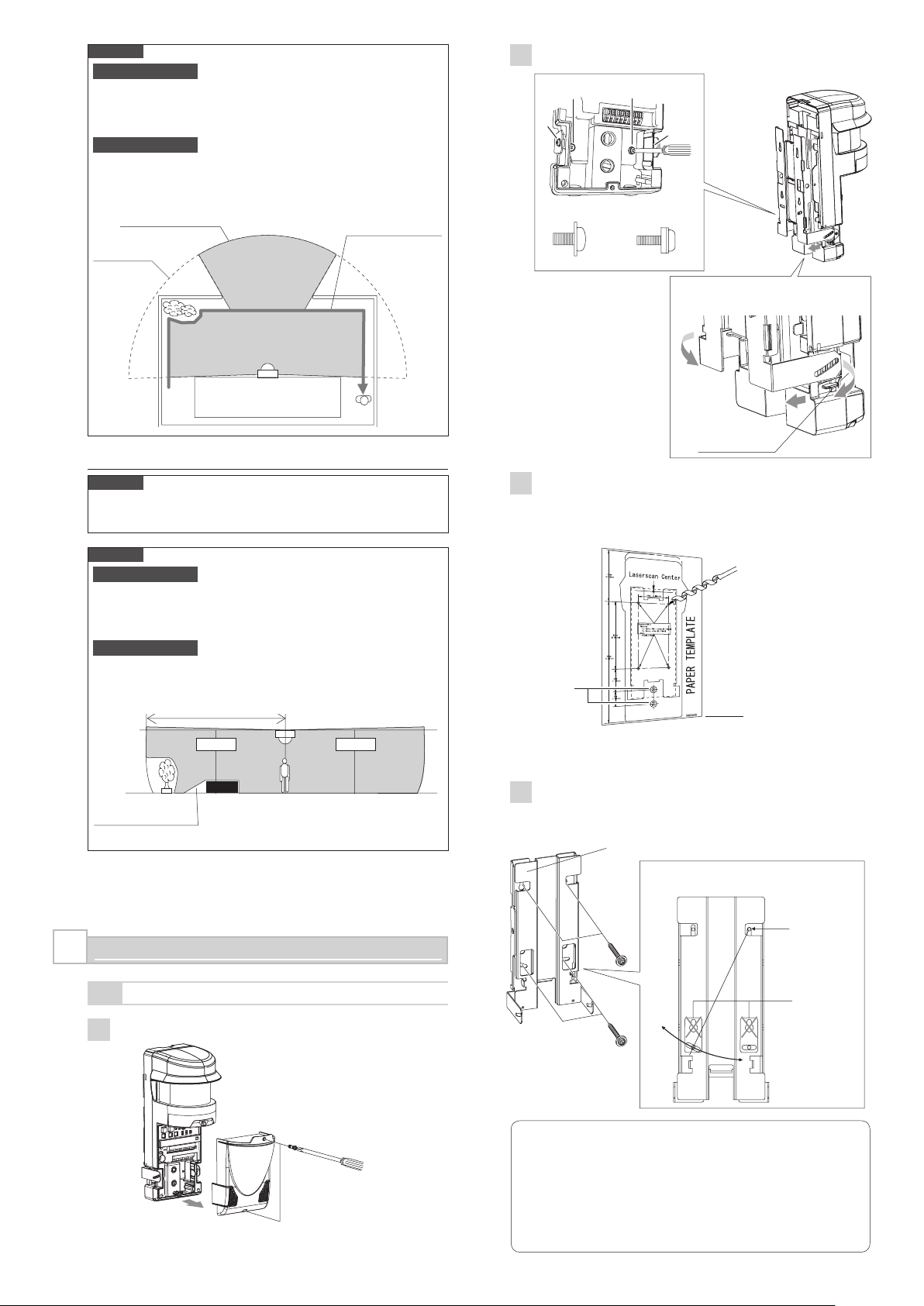
3-1
INSTALLING TO WALL AND ANGLE ADJUSTMENT
1 Remove the cover from the main unit.
2 Remove the mounting bracket from the main unit.
3 Attach the paper template (an accessory) onto the wall, and
drill 4 mounting holes in it. Drill 2 wiring holes as required.
Insert the anchor bolt (an accessory) into the board
mounting holes.
4 Fix the mounting bracket on the wall. Adjust the angle so
that the inclination in the horizontal plane becomes parallel
to the ground.
Cautions>>
When installing the product to the wall, fix the mounting
bracket parallel to the ground. If the mounting bracket is
set at an angle, the laser beam will not be emitted parallel
to the ground, which may result in the non-detection of
an intruder. An inclination of 1 degree varies the shape
of the detection area of 30 m (Approx.
100 ft.) ahead by
approximately 0.5 m (1.6 ft.).
Auto P1 (Auto Learning)
Auto P2 (Auto Tracing)
Manual
Area
A2
Area
A1
Area
B1
Area
B2
30 m maximum (Approx. 100 ft.)
Auto P1 (Fix)
Installation
height
Ground
surface
1
Loosen 2 lock screws.
Main unit fallprotection stopper
(Washer without rubber)
1 Loosen 4 lock screws.
2 Move the
mounting
bracket
3 Remove the mounting bracket by moving it
over the stopper while opening the bottom
of the mounting bracket slightly outward.
They are not
used
A
Mounting hole in 4 locations
Diameter 6 mm (0.24 inches)
Depth
60 mm (2.36 inches)
Set the lower end of the
paper template at a position
at least 0.7 m (28 in.) above
the ground.
Wiring hole
Tighten 4 lock screws for the mounting bracket (accessories).
Adjust the angle along the slot while setting screw
hole A at the center. After the adjustment, tighten
the screws.
Angle adjustment
screws a and b
Main unit mounting
screws c and d
Area A Area B
2
Remove the cover.
(Washer with rubber)
Page 5

- 5 -
ENGLISH FRANÇAIS DEUTSCH ITALIANO ESPAÑOL
a
dc
b
a
dc
b
5 Install the cable gland.
6 Install the main unit and fix it to the mounting bracket.
Adjust the angle so that the inclination in the vertical
direction becomes parallel to the ground.
7 See section “4-1” and connect the wires to the terminal
block.
Cautions>>
When the indicators (A1, A2, B1, B2, Status and Power)
light after the power turns on, this signifies that the system
is warming up. Wait for approximately 30 seconds until the
indicators go out.
8 See Chapters 5, 6 and 7, make various settings and confirm
that the equipment operates correctly.
9 The installation work is complete when the various settings
and operational check are finished. Mount the cover.
3-2
INSTALLING TO CEILING PLANE
AND ANGLE ADJUSTMENT
When you have selected the Vertical Detection Area for detection
purposes, install the product to the ceiling plane.
1 Implement steps 1 and 2 in “3-1” to remove the cover and
mounting bracket.
2 Attach the paper template (an accessory) to the ceiling
plane and drill 4 mounting holes in it. Drill 2 wiring holes as
required.
Insert the anchor bolt (an accessory) into the board
mounting holes.
3 Fix the mounting bracket to the ceiling plane.
4 Install the main unit and fix it to the mounting bracket. Adjust
the angle so that the inclination in the vertical direction
becomes parallel to the ground.
5 Take steps 6 through 9 in “3-1” to do wiring, check the
setup and operation, and then install the cover.
1 Install the main unit by moving it over the
stopper while opening the bottom of the
mounting bracket slightly outward.
Ensure that any unused
wiring holes are covered
securely with a wiring
hole cap.
Cable gland
Main unit fallprotection stopper
3
Tighten 4 lock screws.
Angle adjustment
screws a and b
Main unit mounting
screws c and d
(Washer without
rubber)
2
Insert the top portion
When tightening screws a and b,
adjust the angle referencing the
slot.
2
Tighten 2 lock screws.
1
Install the cover.
Wiring hole
Peel off the paper template from the portion indicated
with the dotted line when using its inner portion alone.
Mounting hole in 4 locations
Diameter 6 mm (0.24 inches)
Depth
60 mm (2.36 inches)
Tighten 4 lock screws
for the mounting
bracket (accessories).
They are not
used
Main unit fallprotection stopper
1 Install the main unit by moving it over the
stopper while opening the bottom of the
mounting bracket slightly outward.
2
Insert the top portion.
3
Tighten 4 lock screws.
(Washer without
rubber)
(Washer with rubber)
Angle adjustment
screws a and b
When tightening screws a and b,
adjust the angle along the slot.
5°
5°
5°
5°
(Washer with rubber)
Main unit mounting
screws c and d
Page 6

- 6 -
- 7 -
3-3
INSTALLING TO POLE
When installing the product to a pole, use the optional pole
mounting bracket (RLS-PB).
1 Take steps 1 and 2 in “3-1” to remove the cover and
mounting bracket.
2 Fix the pole mounting bracket (optional) to the pole using 2
stainless belts (included in the pole mounting bracket).
Points >>
For detailed handling procedures, see the manual attached
to the pole mounting bracket.
3 Fix the mounting bracket to the pole mounting bracket.
For the fixing, use the screw with the washer attached to
the pole mounting bracket. Adjust the angle so that the
inclination in the horizontal plane becomes parallel to the
ground.
4 Take step 6 in “3-1” to install and fix the main unit to the
mounting bracket.
5 Take steps 7 through 9 in “3-1” to do wiring, check the
setup and operation, and then install the cover.
3-4
INSTALLING AT AN ANGLE TO WALL
OR CEILING PLANE
When installing the product at an angle to a wall or ceiling plane,
use the optional adjustable angle mounting bracket (RLS-SB).
1 Take steps 1 and 2 in “3-1” to remove the cover and
mounting bracket.
2 When installing the product at an angle to a wall, attach the
paper template (attached to the main unit) to the wall and
drill 4 mounting holes in it in the same way as described
in “3-1
3
.” For the ceiling plane, follow the procedures
described in “3-2 2.”
Points >>
The mounting holes for the adjustable angle mounting
bracket must be provided in the same position, diameter
and depth as that for the main unit mounting holes
indicated on the paper template.
3 Fix the optional adjustable angle mounting bracket to the
wall or ceiling plane using 4 screws attached to the main
unit.
Wall Ceiling plane
Points >>
For detailed handling procedures, see the manual attached
to the adjustable angle mounting bracket.
4 Fix the mounting bracket with 4 lock screws with the washer
attached to the optional adjustable angle mounting bracket.
Wall Ceiling plane
5 Take step 6 in “3-1” to install and fix the main unit to the
mounting bracket.
Wall Ceiling plane
6 Take steps 7 through 9 in “3-1” to carry out wiring, check
the setup and operation, and then install the cover.
Stainless belt
(included in the
pole mounting
bracket)
Pole mounting
bracket (optional)
The angle varies according to the bolt
insertion position.
The angle varies according to the bolt
insertion position.
45°
40°
30°
20°
30°
45°
40°30°20°10°
10
°
0°
45°
Page 7

3-5
INSTALLING AT AN ANGLE TO POLE
When installing the product at an angle to a pole, use the optional
adjustable angle mounting bracket for pole (RLS-SB).
1 Take steps 1 and 2 in “3-1” to remove the cover and
mounting bracket.
2 Fix the optional adjustable angle mounting bracket to the
pole using 2 stainless belts (included in the adjustable angle
mounting bracket).
Stainless belt
(included in the
pole mounting
bracket)
Power wires should not exceed the following lengths.
WIRE
SIZE
AWG20
(0.52 mm2)
AWG18
(0.83 mm2)
4-2
24V DC 24V AC
120
(394)
200
(656)
60
(197)
100
(328)
m (ft.)
RESET SWITCH
Stripped wire length
Wires must be stripped back 9 mm.
Use the gauge on the panel for
correct measurement.
This switch is used for restarting the system.
Do not touch it during normal operation.
4-3
SIGNAL OUTPUT
9 mm
ENGLISH FRANÇAIS DEUTSCH ITALIANO ESPAÑOL
Adjustable angle
mounting bracket
3 Fix the mounting bracket with 4 lock screws with the washer
attached to the optional adjustable angle mounting bracket.
4 Take step 6 in “3-1” to install and fix the main unit to the
mounting bracket.
5 Take steps 7 through 9 in “3-1” to do wiring, check the
setup and operation, and then install the cover.
-D.Q. output
The algorithm specific to REDSCAN allows
detecting an intrusion amid the fog. However,
during severe conditions such as heavy rain,
dense fog or snow storms the Environmental
DisQualification (EDQ) output is activated.
-Alarm output
Upon detecting an intruder, this product outputs the alarm specific
to the area (Area A1, Area A2, Area B1 or Area B2) where the
intrusion happened.
When combined with an area monitoring system using a PTZ
camera, this product works efficiently to provide early detection of
intruders.
-Tamper output
This output is enabled when the terminal cover is
removed.
-Trouble output
It is generated when an error has occurred on the
sensor.
Name Function
4
PARTS LAYOUT INSIDE THE COVER AND THEIR FUNCTIONS
4-1
WIRING
RESET
Switch
D.Q OUTPUT (N.C.)
D.Q OUTPUT (N.O.)
A2 area ALARM OUTPUT (N.O.)
A1 area ALARM OUTPUT (N.O.)
B1 area ALARM OUTPUT (N.O.)
B2 area ALARM OUTPUT (N.O.)
TAMPER OUTPUT (N.C.)
A
r
e
a
A
A
r
e
a
B
A
u
to
F
u
n
c
1
6
1
6
1
2
1
2
2
0
2
0
7
H1
7
Rang
e
P1
2
4
2
4
8
8
H2
P2
V
4
2
8
4
2
8
0
0
O
f
f
s
e
t
Fine
adj
.
-1 +
1
-1 +
1
-1 0
TROUBLE OUTPUT (N.O.)
MAINTENANCE
CONNECTOR
WALK TESTER
CONNECTOR
POWER INPUT
TROUBLE OUTPUT (N.C.)
ALARM OUTPUT (N.O.)
ALARM OUTPUT (N.C.)
*1: TAMPER terminals to be connected to a 24 hour supervisory loop.
It is activated when an obstacle
has been placed in front of the
sensor in order to block the
Anti-masking
detection area. It is reset after
such obstacles are removed.
Heavy soiling of the front
window can also activate this
function.
This function is activated
when the area being scanned
changes by a signicant
Anti-rotation
amount as a result of the unit
being rotated from its original
settings. Not applicable in
Manual mode.
.
S
A1
e
t
A2
B
1
B
2
Status
Powe
r
S
e
n
s
.
S
iz
e
M
o
d
e
H
S
M
M
M
A
L
L
5
7
3
1
2
4
0
Sensor error
It is activated when the sensor
has detected an internal self
check error.
-Alarm output
The alarm output is generated if an intruder is
detected in one or more of the divided areas (Area
A1, Area A2, Area B1 and Area B2).
- 7 -
Page 8

- 8 -
- 9 -
REDWAVE
REDWAVE
MICROWAVE
REDWAVE
ALARM OUTPUT
CELL BATTERY
POWER
SUPPLY
FROM
SENSOR
POWER OFF
REDWAVE
PIR NEAR
REDWAVE
PIR FAR
MEGARED
FAR
MEGARED
NEAR
REDWALL
REDWIDE
WALKTESTER
REDWALL
REDWIDE
MEGARED
CONNECTION
SELECT
SWITCH
MODE
SELECT
SWITCH
POWER
SELECT
SWITCH
OPM-WT
Set A2
Power
A1
B1 B2
Status
Set A2
Powe
r
A1
B1 B2
Status
F
in
e
adj.
A
u
t
o F
u
n
c
.
S
e
t
P1
P2
H1
V
H2
O
f
f
s
e
t
S
e
n
s
.
H
M
L
S
i
z
e
S
M
L
A
r
e
a
A
A2
Powe
r
-1 +
1
-1 +
1
-1 0
A1
B
1
B
2
A
r
e
a
B
5
7
3
1
2
4
0
Status
Range
M
o
d
e
M
A
0
8
1
6
2
4
4
1
2
2
0
2
8
0
4
8
1
2
1
6
2
0
2
4
2
8
7
7
Fine
adj.
Auto Func. Set
P1
P2
H1
V
H2
Offset
Sens.
H
M
L
Size
S
M
L
Area A
A2
Power
-1 +1 -1 +1 -1 0
A1
B1 B2
Area B
5731240
Status
Range
Mode
M
A
0
8
16
24
4
12
20
2804
8
12
16
20
24
28
7
7
Set A2
Powe
r
A1
B1 B2
Status
SETTING HORIZONTAL DETECTION AREAS 1 AND 2
5
4-4
CONNECTING WALK TESTER
1 Turning on the power selector switch after plugging
the cable into the Walk Tester Connector generates a
continuous beep at a constant sound level.
2 The beep sound becomes stronger and continues for a
longer period if an object is detected.
4-5
POWERING ON
Connect 24 VAC/DC to the power input terminal to
turn power on.
As power is turned on, the indicators (A1, A2, B1,
B2, Status and Power) light for about 30 seconds
and then go out.
During this period, REDSCAN initializes itself.
Indicator Power remains lit as long as power is
turned on.
Legend OFF Light Blink
4-6
SWITCH LAYOUT
4-7
LED FUNCTIONS
-In the normal operation
Symbol Color DETECTOR STATUS
A2 Red
Area A2 alarm output
A1
Red
Area A1 alarm output
B1
Red
Area B1 alarm output
B2 Red Area B2 alarm output
Status Yellow
Lit during auto setup of the unit.
(Turned off during normal operation.)
Power Green Lit when power is turned on
-When an abnormality occurs
Status
A2 A1 B1 B2
Status
Power
D.Q.
Anti-masking
Anti-rotation
Sensor
error
Error 1
Error 2
Error 3
Error 4
Error 5
Legend OFF Light Blink
5-1
SELECTOR SWITCH OPERATION
-Detection method selection
H1 Manual H1 Auto H2 Manual H2 Auto V Auto
Select the desired method using the detection
method selector switch.
Func.
H1
V
H2
SELECTOR
POSITION
FUNCTION
H1
It selects Horizontal Detection Area 1.
H2
It selects Horizontal Detection Area 2.
V
—
-Selection of the area setting method
H1 Manual H1 Auto H2 Manual H2 Auto V Auto
Select the desired method using the mode
selector switch.
Mode
M
A
SELECTOR
POSITION
FUNCTION
M
Selects the Manual setting.
A
Selects the Auto setting.
-Selecting the Auto mode
H1 Manual H1 Auto H2 Manual H2 Auto V Auto
Select it using the Auto mode selector switch.
Auto
P1
P2
SELECTOR
POSITION
FUNCTION
P1
Turns on the Auto Learning.
P2
Turns on the Auto Tracing.
Area A2 alarm output
Area A1 alarm output
Area B1 alarm output
Area B2 alarm output
Power selector
switch
Use at “REDWALL”
position.
WALK TESTER <OPM-WT>
REDSCAN
Approximately
30 seconds
(Initialization is
turned on)
Auto mode selection
Detection method selection
Detection area setting button
Operation Indicator
Tamper switch
Mode selection
Detection sensitivity setting (Size.)
Detection sensitivity setting (Sens.)
Offset adjustment
Area A ne alignment
potentiometer
Area B
ne alignment
potentiometer
Area A rough
alignment
Area B rough
alignment
Page 9

- 9 -
ENGLISH FRANÇAIS DEUTSCH ITALIANO ESPAÑOL
Area B Area A
0
8
16
24
4
12
20
28
0
4
8
12
16
20
24
28
7
F
Fine
adj.
Area A
-1 +1 -1 +1
Area B
Range
0
8
16
24
4
12
20
2804
8
12
16
20
24
28
7
F
Offset
-1 0
Set A2
Set A2
Power
A1
B1 B2
Status
REDWAVE
REDWAVE
MICROWAVE
REDWAVE
ALARM OUTPUT
CELL BATTERY
POWER
SUPPLY
FROM
SENSOR
POWER OFF
REDWAVE
PIR NEAR
REDWAVE
PIR FAR
MEGARED
FAR
MEGARED
NEAR
REDWALL
REDWIDE
WALKTESTER
REDWALL
REDWIDE
MEGARED
CONNECTION
SELECT
SWITCH
MODE
SELECT
SWITCH
POWER
SELECT
SWITCH
OPM-WT
1
2
Auto
P1
P2
-Selecting the detection sensitivity
H1 Manual H1 Auto H2 Manual H2 Auto V Auto
Set the detection sensitivity using the Size selector switch and
Sens. selector switch. You can set the detection sensitivity in the
horizontal area with the size of the target object and its move
distance within the detection area.
H
M
L
S
M
L
Size
Sens.
SELECTOR
POSITION
FUNCTION
S
Approx. 150 mm
(0.5 ft.) or above
This switch
species
the width of
the target
object to be
detected.
M
Approx. 300 mm
(1 ft.) or above
L
Approx. 1000 mm
(3.3 ft.) or above
H
Approx. 500 mm
(1.6 ft.) or above
This switch
species
the move
distance of an
object in the
detection area
above which
it is judged as
an intruder.
M
Approx. 1000 mm
(3.3 ft.) or above
L
Approx. 2000 mm
(6.6 ft.) or above
5-2
MANUAL SETTING OF HORIZONTAL DETECTION AREA
H1 Manual H1 Auto H2 Manual H2 Auto V Auto
Set a fan-like detection area using the rough alignment rotary
switch and fine alignment potentiometer.
-Rough alignment rotary switch
You can specify the radius in the range of 0 to 30 m in 2 m steps.
Setting the rough alignment rotary switch to 0 m deletes the area.
Example: if you specify “Detection distance in Area A: 30 m”
and “Detection distance in Area B: 14 m” in a location where the
radius is 30 m or more without a reflector, the following detection
areas will result.
SELECTOR
POSITION (m)
[ft.]
0 0
4 13
8 26
12
39
16
52
20 65
24 79
28 92
-Fine alignment potentiometer
This potentiometer can fine tune the value set with the rough
alignment rotary switch by +/- 1 m. within the range of 0 m
minimum and 30 m maximum.
Setting done in rough
alignment
Range available for fine alignment
When 0 m is set
0 to +1 m (From -1 to 0 m on the scale
is not usable)
When 2 to 28 m is set ±1 m
When 30
m is set
-
1 to 0 m (From 0 to +1 m on the scale
is not usable)
-Offset adjustment
You can reduce a set detection area using the offset
potentiometer. Use this adjusting function when windblown grass
or tree branches interfere with the currently set detection area.
You can adjust the boundary of a given detection area inward
(toward the sensor) in the range of 0 to -1 m.
5-3
STARTING SECURITY PROTECTION IN MANUAL MODE
H1 Manual H1 Auto H2 Manual H2 Auto V Auto
When “Manual” is chosen from the mode selector
switch, turning the power on starts the security
protection in manual mode.
5-4
AUTO SETTING OF HORIZONTAL DETECTION AREA
-Function of the detection area setting button
H1 Manual H1 Auto H2 Manual H2 Auto V Auto
This button starts the auto function of either P1 or
P2 whichever has been selected.
-Setting P1 (Auto Learning)
H1 Manual H1 Auto H2 Manual H2 Auto V Auto
Sequence of
operation
Status
indicator
Time
Action of REDSCAN/
Response of Walk Tester
1
Hold down the
detection area setting
button for 1 second.
Flashing
starts
For
1 second
Pitch of Walk Tester
sound changes for
2 seconds
2
Evacuation from
the area
Flashing (*1)
For
15 seconds
—
—
Fast flashing
(*2)
For
10 seconds
Scan of the detection
area is executed
—
ON
For
15 seconds
Scan of the detection
area is completed and
the data are saved
—
Flashing
For
3 seconds
—
—
OFF
—
Security protection of the
detection area is started
*1: Flashes once a second
*2: Flashes twice a second
Cautions >>
Do not enter the area while the area scan is being carried
out.
An unwanted object in the area interferes with the correct
scanning of the target area.
Offset
Offset
Auto P1 (Auto Learning)
Manual Mode
AreaB2AreaB1Area
A1
Area
A2
15 m
7 m
30 m14 m
: Detection area
Page 10

- 10 -
- 11 -
Auto
P1
P2
2
3
Set A2
Power
A1
B1 B2
Status
REDWAVE
REDWAVE
MICROWAVE
REDWAVE
ALARM OUTPUT
CELL BATTERY
POWER
SUPPLY
FROM
SENSOR
POWER OFF
REDWAVE
PIR NEAR
REDWAVE
PIR FAR
MEGARED
FAR
MEGARED
NEAR
REDWALL
REDWIDE
WALKTESTER
REDWALL
REDWIDE
MEGARED
CONNECTION
SELECT
SWITCH
MODE
SELECT
SWITCH
POWER
SELECT
SWITCH
OPM-WT
1
Area BArea A
0
8
16
24
4
12
20
28
0
4
8
12
16
20
24
28
7
F
SETTING VERTICAL DETECTION AREA
6
-Setting P2 (Auto Tracing)
H1 Manual H1 Auto H2 Manual H2 Auto V Auto
Sequence of
operation
Status
indicator
Time
Action of REDSCAN/
Response of Walk Tester
1
Hold down the
detection area setting
button for 1 second.
Flashing
starts
For
1 second
Pitch of Walk Tester
sound changes for
2 seconds
2
Evacuation from
the area
Flashing
(*2)
For
15 seconds
—
—
Fast flashing
(*3)
For
10 seconds
Scan of the detection
area is executed
3
Walking along the
boundary of the area
(*1)
Flash
(*4)
For
5 minutes
Tracing started
Pitch of the Walk Tester
sound changes in
3-second cycles
(Last
30 seconds)
Pitch of the Walk Tester
sound changes in
1-second cycles
—
ON
For
15 seconds
Tracing is completed and
the data are saved
—
Flashing
For
3 seconds
—
—
OFF
—
Security protection of the
detection area is started
*1: The tracing is automatically ended after 5 minutes. When
movement of the target object along the area boundary has
finished before this time, you can terminate the tracing without
waiting for 5 minutes by holding down the detection area
setting button for 3 seconds.
*2: Flashes once a second
*3:
Flashes twice a second
*4: A flashin g sequen ce of flashing twice a second and n ot
flashing for a second is repeated
Cautions >>
Do not enter the area while the area scan is being carried
out. An unwanted object in the area interferes with the
correct scanning of the target area.
Note >>
Any area left untraced will revert to the Auto learning area
settings.
6-1
SELECTOR SWITCH OPERATION
-Detection method selection
H1 Manual H1 Auto H2 Manual H2 Auto V Auto
Select the desired method using the detection
method selector switch.
Func.
H1
V
H2
SELECTOR
POSITION
FUNCTION
H1
—
H2 —
V
Selects the vertical detection area.
-Selection of the area setting method
H1 Manual H1 Auto H2 Manual H2 Auto V Auto
Select the desired method using the mode
selector switch.
Mode
M
A
SELECTOR
POSITION
FUNCTION
M
NOT APPLICABLE
A
Selects the Auto setting.
-Selecting the Auto mode
H1 Manual H1 Auto H2 Manual H2 Auto V Auto
Select it using the Auto mode selector switch.
Auto
P1
P2
SELECTOR
POSITION
FUNCTION
P1
Fixes the detection area.
P2
Periodically refreshes the detection
area.
-Setting the detection sensitivity
H1 Manual H1 Auto H2 Manual H2 Auto V Auto
Set the detection sensitivity using the Size selector switch and
Sens. selector switch. You can set the detection sensitivity in the
vertical area with the size of the target object and the time it takes
to traverse the detection area.
H
M
L
S
M
L
Size
Sens.
SELECTOR
POSITION
FUNCTION
S
Approx. 300 mm
(1 ft.) or above
This switch
species the
height from
offset position
of the target
object to be
detected.
M
Approx. 500 mm
(1.6 ft.) or above
L
Approx. 1000 mm
(3.3 ft.) or above
H
100 ms or longer. This
setting is recommended
when the target object
can run through the
detection area.
This switch
species
the duration
during which
the target
object stays in
the detection
area.
M 150 ms or longer
L
200 ms or longer. This
setting is recommended
when detecting large
objects such as a car.
6-2
SETTING DETECTION AREA IN
VERTICAL DETECTION AREA
H1 Manual H1 Auto H2 Manual H2 Auto V Auto
Set a fan-like detection area using the rough alignment rotary
switch and fine alignment potentiometer.
-Rough alignment rotary switch
It can specify the radius in the range of 0 to 30 m in 2 m steps.
Setting the rough alignment rotary switch to 0 m deletes the area.
SELECTOR
POSITION (m)
[ft.]
0 0
4 13
8 26
12
39
16
52
20 65
24 79
28 92
Auto P1 (Auto Learning)
Manual Mode
Area
B2
Area
B1
Area
A1
Area
A2
: Detection area
Installation
height
Ground surface
15 m
7 m
30 m 14 m
Page 11

- 11 -
ENGLISH FRANÇAIS DEUTSCH ITALIANO ESPAÑOL
Fine
adj.
Area A
-1 +1 -1 +1
Area B
Range
0
8
16
24
4
12
20
2804
8
12
16
20
24
28
7
F
Offset
-1 0
2
Set A2
Power
A1
B1 B2
Status
REDWAVE
REDWAVE
MICROWAVE
REDWAVE
ALARM OUTPUT
CELL BATTERY
POWER
SUPPLY
FROM
SENSOR
POWER OFF
REDWAVE
PIR NEAR
REDWAVE
PIR FAR
MEGARED
FAR
MEGARED
NEAR
REDWALL
REDWIDE
WALKTESTER
REDWALL
REDWIDE
MEGARED
CONNECTION
SELECT
SWITCH
MODE
SELECT
SWITCH
POWER
SELECT
SWITCH
OPM-WT
1
Set A2
Power
A1
B1 B2
Status
REDWAVE
REDWAVE
MICROWAVE
REDWAVE
ALARM OUTPUT
CELL BATTERY
POWER
SUPPLY
FROM
SENSOR
POWER OFF
REDWAVE
PIR NEAR
REDWAVE
PIR FAR
MEGARED
FAR
MEGARED
NEAR
REDWALL
REDWIDE
WALKTESTER
REDWALL
REDWIDE
MEGARED
CONNECTION
SELECT
SWITCH
MODE
SELECT
SWITCH
POWER
SELECT
SWITCH
OPM-WT
-Fine alignment potentiometer
This potentiometer can fine tune the value set with the rough
alignment rotary switch by +/- 1 m. within the range of 0 m
minimum and 30
m maximum.
Setting carried out in
rough alignment
Range available for fine alignment
When 0 m is set
0 to +1 m (From -1 to 0 m on the scale
is not usable)
When 2 to 28 m is set
±1 m
When 30 m is set
-1 to 0 m (From 0 to +1 m on the scale
is not usable)
-Offset adjustment
You can reduce a set detection area using the offset
potentiometer. Use this adjusting function when windblown
grasses or tree branches interfere with the currently set detection
area.
You can adjust the dead zone from the ground in the range of 0
to -1 m.
6-3
AUTO SETTING OF VERTICAL DETECTION AREA
H1 Manual H1 Auto H2 Manual H2 Auto V Auto
Sequence of
operation
Status
indicator
Time
Action of REDSCAN/
Response of Walk Tester
1
Hold down the
detection area setting
button for 1 second.
Flashing
starts
For
1 second
Pitch of Walk Tester
sound changes for
2 seconds
2
Evacuation from
the area
Flashing
(*1)
For
15 seconds
—
—
Fast
flashing (*2)
For
10 seconds
Scan of the detection
area is executed
—
ON
For
15 seconds
Scan of the detection
area is completed and
the data are saved
—
Flashing
For
3 seconds
—
—
OFF
—
Security protection of
the detection area is
started
*1: Flashes once a second
*2: Flashes twice a second
Cautions >>
Do not enter the area while the area scan is being carried
out. An unwanted object in the area interferes with the
correct scanning of the target area.
7-1
WALK TEST
H1 Manual H1 Auto H2 Manual H2 Auto V Auto
Ensure that the detection area has been correctly set referencing
the red indicator and changes in the pitch of Walk Tester sound.
-When a detection area has not been correctly set
1 Before pressing the detection area setting button, ensure
that the detection method switch and the detection mode
switch are set to the correct position, respectively.
2 Set the detection again with reference to “5-4” for the
horizontal detection area and “6-3” for the vertical detection
area.
7-2
CHANGING THE SETTINGS DURING SECURITY PROTECTION
H1 Manual H1 Auto H2 Manual H2 Auto V Auto
You can change the following settings as required during the
security protection.
It is not necessary to press the detection area setting button after
conducting a change.
SELECTOR
NAME
Manual (M) Auto (A) <P1/P2>
Mode selector
Object size
Object movement
Rough alignment
Fine alignment
Offset
—
If you shift the mode selector switch from Manual (M) to Auto (A),
the area that has been specified previously in Auto (A) is selected
as the detection area. When the area is not set in Auto, set it with
reference to the procedure described in “5-4” or “6-3.”
Summary of detection area switch settings
Function
AUTO MODE
(Press Detection area setting button to initiate)
MANUAL MODE
P1
P2
H1
Automatically learns
the detection area
within 1 m x area set by
Rough alignment rotary
switches and Fine adj.
potentiometers
N/A
Detection area
is 1 m x Area
set by Rough
alignment
rotary switches
and Fine adj.
potentiometers
H2 Automatically learns
the detection area
within the area set by
Rough alignment rotary
switches and Fine adj.
potentiometers
Automatically learns the
detection area by tracing
a person walking a
boundary within the area
set by Rough alignment
rotary switches and Fine
adj. potentiometers
Detection area is
the Area set by
Rough alignment
rotary switches
and Fine adj.
potentiometers
V Automatically learns
the detection area
within the area set by
Rough alignment rotary
switches and Fine adj.
potentiometers
Automatically updates the
detection area every hour
within the area set by
Rough alignment rotary
switches and Fine adj.
potentiometers
N/A
AREA CHECKUPS
7
Offset
Ceiling
Ground
surface
Installation
height
Area
B2
Area
B1
Area
A1
Area
A2
Installation
height
Ground surface
Manual
Auto P1 (Fix)
Area A Area B
Area
A1
Area
B1
Area
B2
Area
A2
Ensure that the action of walking into an area causes
the corresponding red indicator to turn on.
30 m
Page 12

- 12 -
OPTEX CO., LTD. (JAPAN)
(ISO 9001 Certified)
(ISO 14001 Certified)
5-8-12 Ogoto Otsu
Shiga 520-0
101
JAPAN
TEL:+81-77-579-8670
FAX:+8
1-77-579-8190
URL:http://www.optex.co.jp/e/
OPTEX INCORPORATED (USA)
TEL:+1-909-993-5770
Tech:(800)966-7839
URL:http://www.optexamerica.com
OPTEX (EUROPE) LTD. (UK)
TEL:+44-1628-631000
URL:http://www.optexeurope.com
OPTEX SECURITY SAS (FRANCE)
TEL:+33-437-55-50-50
URL:http://www.optex-security.com
OPTEX SECURITY Sp.z o.o. (POLAND)
TEL:+48-22-598-06-55
URL:http://www.optex.com.pl
8-1
SPECIFICATIONS OF THE MAIN UNIT
Model RLS-3060
Detection method Infrared Laser Scan
Laser protection
class
Class 1
Wavelength of laser
emission
905 nm (infrared laser)
Coverage for vertical
mounting
Radius: 30 m (Approx. 100 ft.), Arc: 190
°
Coverage for
horizontal mounting
MAX. 60 m (Approx. 200 ft.)
Detection resolution 0.25°
Power input 24V AC/DC ± 10%
Power consumption 400 mA (24VDC) 600 mA (24VAC)
Vertical mounting
height
15 m (Approx. 50 ft.) max
Horizontal mounting
height
0.7 m (28 in.) (recommended)
Indicator
A2 alarm
Red LED
A1 alarm
B1 alarm
B2 alarm
Status Yellow LED
Power Green LED
Area alarm output N.O. 28V DC, 0.2A × 4outputs
Master alarm output Form C, 28V DC, 0.2A max.
Trouble output Form C, 28V DC, 0.2A max.
Tamper output N.C. 28V DC, 0.1A max.
Environmental
disqualication
circuit
Form C, 28V DC, 0.2A max.
Alarm period Approx. 2 sec. Off delay timer
Warm-up period Approx. 30 sec.
Operating
temperature
-20 – +60 °C (-4 – +140 °F)
IP rating IP65
Dimensions
(H × W × D)
334 × 144 × 155 mm
(13.2
× 5.7 × 6.1 in.)
Weight 3 kg (106 oz.)
Accessories
Mounting screw, anchor bolt for board,
paper template, waterproof plug and
Installation Instructions
* Specifications and design are subject to change without prior
notice.
8-2
DIMENSIONAL DRAWING
8-3
OPTIONS
OPM-WT : Audio Walk Tester
RLS-PB : Pole mount bracket
RLS-SB
: Adjustable angle mounting bracket
SPECIFICATIONS
8
7-3 SYSTEM FUNCTION AFTER POWER FAILURE
H1 Manual H1 Auto H2 Manual H2 Auto V Auto
Even if the power is shut down during the security protection
process (detection area is specified) due to reasons including
power failure, the specified detection area is saved on this
product. After power is restored, the product resumes intruder
detection normally in the detection area that was specified prior
to the power failure.
144
(5.7)
155
(6.1)
64
(2.5)
18
(0.7)
334
(13.2)
135
(5.3)
92
(3.6)
107
(4.3)
Unit:mm (inch)
 Loading...