


Reference and Instruction Manual
Optec¨ Vision Tester
8623 W. Bryn Mawr Ave., Suite 502, Chicago, IL 60631 USA 1.773.867.0380 or 1.800.344.9500
facsimile: 1.773.867.0388 email: sales@stereooptical.com www.stereooptical.com
¨
STEREO OPTICAL
Optec is a registered trademark of Stereo Optical Co., Inc.

Reference and Instruction Manual
Model 5000 Vision Tester
For Model 5000(P) Manual
&
Model 5500(P) Motorized
VisionTester
8623 W. Bryn Mawr Ave., Suite 502, Chicago, IL 60631 USA 1.773.867.0380 or 1.800.344.9500
facsimile: 1.773.867.0388 email: sales@stereooptical.com www.stereooptical.com
¨
STEREO OPTICAL
Optec is a registered trademark of Stereo Optical Co., Inc. |
P/N 32175 |
Introduction
Good vision is a precious gift, which should be guarded, cherished, and nurtured throughout life.
To maintain good vision, frequent vision screenings and periodic visual exams are necessary. In this way, an awareness of inadequate vision or changes in vision can be noted. The eye-care professional can then correct most visual problems. Without these screenings, many children and adults would have undetected visual difficulties, having a direct effect on their quality of life.
Eye-care professionals feel that the earlier vision screening can begin, the more rewarding the results can be. This attention should be continued throughout adult life, with specific attention to the working years.
Stereo Optical's Model 5000 Vision Tester does this screening efficiently. It is a precision instrument designed to do quick, accurate, reliable, and confidential screening. It will identify those who have a problem and need professional assistance.
1
External Features
1. Forehead Activator: Controls illumination inside the Vision Tester. It will only activate the lights when the subject maintains pressure against the activator, insuring the subject to be at a proper distance for testing. When forehead pressure is applied to the bar, the green "Ready" indicator will be illuminated on the control panel and the subject will be ready to be tested.
2.Headrest Tissue: The tissue cushions the subject's forehead while allowing maximum hygienic conditions.
3.Lens System: The upper lenses are for FAR Point testing (simulated distance of 20 ft.) The subject looks straight ahead. The lower lenses are for NEAR Point testing (simulated distance of
16in.) with the subject looking down while holding his/her head straight. The lenses are easily accessible for cleaning and the face plate is wide enough to accommodate wide contemporary eyeglass frames.
4.Instrument Base: It gives a stable foundation for the vision tester in all positions.
5.Elevation Adjustment: Simply depress the button in the base and adjust the instrument to the desired height for each subject. Release button and the instrument is locked in place.
6.Observation Doors: The observation doors, located on both sides of the unit, allow the tester easy access to both FAR and NEAR test slides. A pointer can be used by the tester to assist the subject in identifying the targets. The pointer is held in place by clips inside the door. The doors are held closed with magnets.
7.FAR and NEAR Indicators: These lights indicate how the instrument is set to test accordingly.
8.Test Dial and Knob: Located on both sides of the unit, is used to change slides in the viewing area. The ribbed knob turns the dial easily and can go forward or reverse. The numbers on the dial correspond to the numbers on the record form for identifying the test slide. The number under the lit indicator is the number of the test in the viewing area. On the Model 5500 (motor-driven) Vision Tester, this small knob should not be used. All slides should be advanced from buttons on the remote control panel.
9.Electronic Control Panel: Operates the functions of the vision tester, power switch, right and left eye switches, Near and Far switches, and the optional peripheral test controls.
10.Instrument Body: The Instrument Body is lightweight and is made of flame retardant ABS plastic.
11.Carrying Handle: Built-in for maximum convenience. The rigid handle and lightweight body aid in ease of portability.
The serial number is located on the inside of the Slide Access Door
2

1 |
Forehead Activator |
7 |
Far and Near Indicators |
2 |
Headrest Tissue Holder |
8 |
Test Dial & Knob |
3 |
Lens System |
9 |
Electronic Control Panel |
4 |
Instrument Base |
10 |
Instrument Body |
5 |
Elevation Adjustment |
11 |
Carrying Handle |
6 |
Observation Door |
|
|
3
Internal Features
1.An advanced light system renders a white homogenous light, resulting in high contrast images and truer color reproduction.
2.Built-in baffle assembly isolates the left and right eye, thus eliminating unwanted reflective light. By eliminating crossover, true binocular and monocular tests are guaranteed.
3.Front surface mirror offers a ghost-free image for more accurate testing of distance vision.
4.Up to 12 test slides can be mounted on a rotatable drum. The slides can easily be removed or replaced in seconds.
5. Stereo Optical's slides are manufactured from a high-resolution photographic film mounted between 2 layers of glass. The high resolution of (500/line pairs/mm) affords a much finer acuity level for more accurate testing.
6. Stereo Optical's slides are transilluminated to eliminate glare and reflection. The result is a more accurate image, therefore a more accurate test.
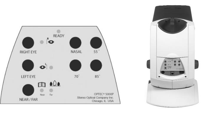
Model 5000P Control Panel
4
Advanced Design Control Panel
The control panel is designed for convenience in both operation and maintenance. The figure on previous page shows the control panel for the Model 5000P with perimeter (Non-motorized).
Right Eye:
When the forehead activator is depressed, the right eye will see the test target. When the switch is turned OFF, the right eye will see nothing. To turn switch ON, depress; to turn OFF, press again.
Left Eye:
When the forehead activator is depressed, the left eye will see the test target. When the switch is turned OFF, the left eye will see nothing. To turn switch ON, depress; to turn switch OFF, press again.
Binocular:
When both the left eye and right eye are activated, a binocular test is being performed.
Far/Near Switch:
When the switch is on, the unit is set for FAR point testing. The testing distance simulated in the instrument is 20 feet. Cycle the test appropriately to achieve the test you desire according to the Near and Far indicators.
Power Switch:
Master On/Off power, (located on the back of the instrument) depress ON, press again for OFF.
Ready Light:
Green light indicates that the subject is pressing against headrest activator and is at proper testing distance.
Perimeter Switches:
Model 5000P Vision tester with perimeter.
The perimeter function is to test the lateral(horizontal) visual field.
Four switches pertain to peripheral vision testing. All are momentary switches; they stay on only if pressure is applied.
35 nasal
55 temporal
70 temporal
85 temporal
The same switches are used for testing both sides, right & left. Depress the eye selector for the eye that is to be tested.
5

Forward and Reverse Switches:
This switch determines direction of the slide advancement. Pressing this switch once advances test slides one at a time. Holding this switch down allows for continual advancement of the test slides until the desired slide is in the correct position.
Remote Control Panel
Model 5500P Motorized Tester
6
 Loading...