

Page 1
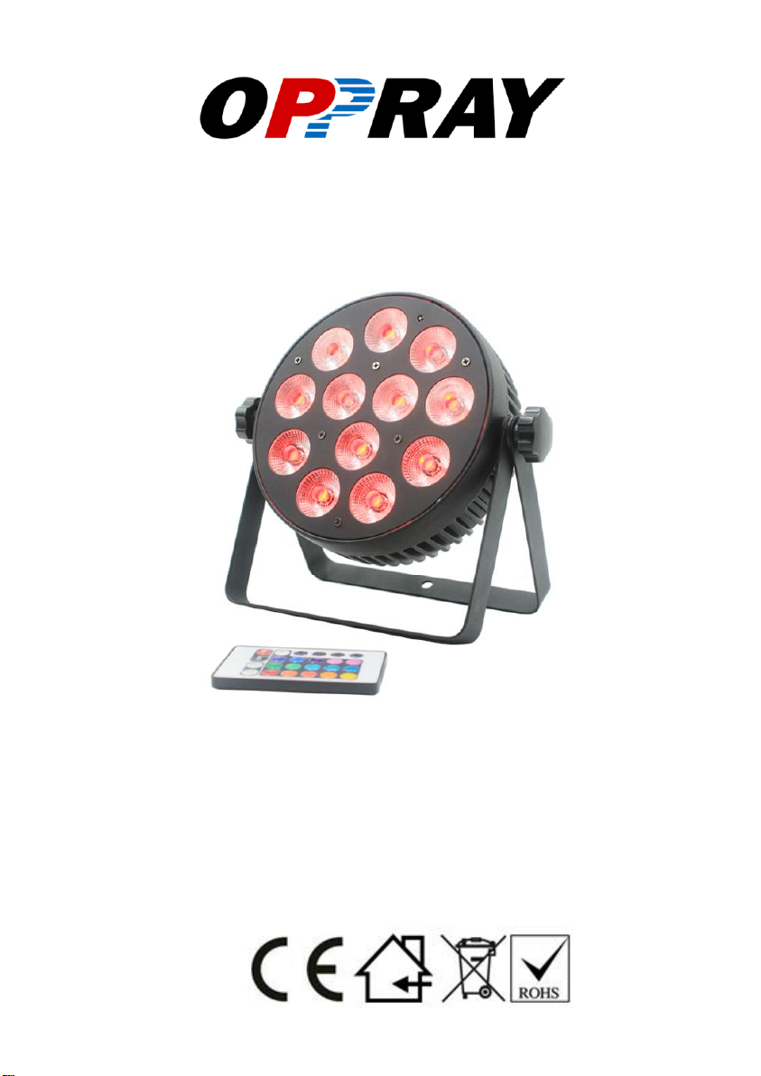
PL-W0124
User Manual
Please read this user manual before using this product.
Page 2

www.oppray-light.com PL-W0124 12 x 8W Flat Par User Manual
INDEX
STATEMENT 3
ACCESSORIES 3
SAFETY INSTRUCTION 4
UNDERSTANDING DMX 7
TECHNICAL SPECIFICATION 10
CONTROL SYSTEM 11
CLEANING AND MAINTENANCE 16
Page 3

www.oppray-light.com PL-W0124 12 x 8W Flat Par User Manual
STATEMENT
The product has well capability and intact packing when
leave factory. All of the user should comply with warning item
and manual, any misuse cause of the damages are not included
in our guarantee, and also cannot be responsible for any
malfunction & problem owing to ignore the manual.
UNPACKING
Every par light has been thoroughly tested and has been shipped in
perfect operating condition. Carefully check the shipping carton for
damage that may have occurred during shipping. If the carton
appears to be damaged, carefully inspect your unit for damage and
be sure all accessories necessary to operate the unit have arrived
intact. In the event damage has been found or parts are missing,
please contact our customer support team for further instructions.
Please do not discard the shipping carton in the trash. Please
recycle whenever possible.
ACCESSORIES
These items are packed together with the product:
Name
Quantity
Unit
Remark
USER MANUAL
1
PCS
DMX CABLE
1
PCS
POWER CABLE
1
PCS
IR Remote Panel
1
PCS
Page 4
www.oppray-light.com PL-W0124 12 x 8W Flat Par User Manual
SAFETY INSTRUCTION
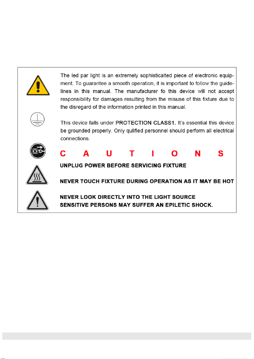
• For proper operation, follow the Installation guidelines described in this
manual. Only qualified and certified personnel should perform installation
of this fixture and only the original rigging parts (brackets) included with
this fixture should be used for installation. Any modifications will void the
original manufactures warranty and increase the risk of damage and/or
personal injury.
• Never look directly into the light source of this fixture to prevent risk of
injury to your retina, which may induce blindness. Those suffering from
EPILEPSY should avoid looking directly into the light source of this unit at
all times.
• Always disconnect from main power source before performing any type of
Page 5

www.oppray-light.com PL-W0124 12 x 8W Flat Par User Manual
service and/or cleaning procedure. Only handle the power cord by the plug
end, never pull out the plug by tugging the wire portion of the cord.
• Do not operate this fixture if the power cord has become frayed, crimped
and/or damaged. If the power cord is damaged, replace it immediately with
a new one of similar power rating.
N EV E R O P E N T H I S F I X T U R E WH I LE I N U S E !
• Ensure ALL connections and end caps are properly sealed with a
dielectric grease (available at most electrical suppliers) to prevent
water corrosion and/or electrical short circuit.
During the initial operation of this fixture, a light smoke or smell may
emit from the interior of the fixture. This is a normal process and is
caused by excess paint in the interior of the casing burning off from
the heat associated with the lamp and will decrease gradually over
time.
• This fixture is a professional lighting effect designed for INDOOR / DRY
LOCATIONS ONLY on stage, in nightclubs, theatres, etc.
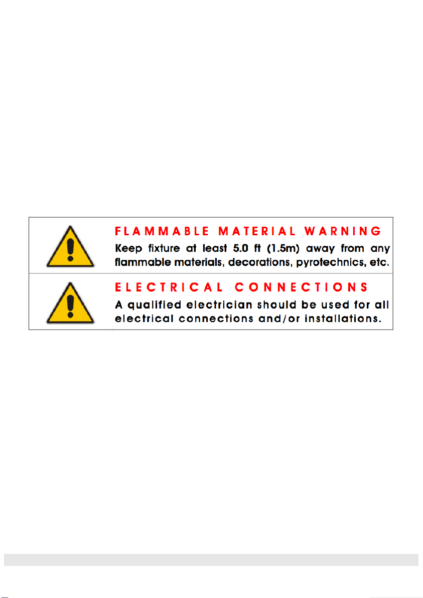
• Please make sure there are NO FLAMMABLE MATERIALS close to the
fixture while operating, to prevent any fire hazard.
• Minimum distance of inflammable materials from the surface 1.6 feet
(0.5m).
• DO NOT attempt installation and/or operation without knowledge how to
do so.
• DO NOT allow operation by persons who are not qualified to operate this
type of fixture. Most damages are the result of operations by
nonprofessionals.
• Consistent operational breaks may ensure the fixture will function properly
for many years to come.
• DO NOT shake fixture, avoid brute force when installing and/or operating
fixture.
• Always install the fixture with an appropriate safety cable. When installing
Page 6
www.oppray-light.com PL-W0124 12 x 8W Flat Par User Manual
the fixture in a suspended environment, always use mounting hardware
that is no less than M10 x 25 mm, also be sure the hardware is insert in
the pre-arranged screw holes in the bracket of the fixture.
• Use the original packaging and materials to transport the fixture in for
service.
• DO NOT TOUCH the housing bare-hand during its operation. Turn OFF
the power and allow approximately 15 minutes for the fixture to cool down
before replacing or serving.
INSTALLATION:
C A U T I O N S
• For added protection, mount the fixture in areas outside walking paths,
seating areas, or in areas were unauthorized personnel might reach the
fixture.
• Min/Max ambient operating temperature for this fixture is 5°F to 113°F (-
15°C to 45°C). Do not use the fixture under or above this temperature.
• Before mounting the fixture to any surface, make sure the installation area
can hold a minimum point load of 10 times the weight of the fixture.
• Fixture installation must always be secured with a secondary safety
attachment, such as an appropriate safety cable.
• Never stand directly below the device when mounting, removing or
servicing.
Page 7

www.oppray-light.com PL-W0124 12 x 8W Flat Par User Manual
•
CLAMP MOUNTING
When mounting this fixture to truss be sure to secure an
appropriately rated clamp using an M10 screw fitted through the
center hole of the Dual Yoke / Floor Stand.
SECURING
Regardless of the rigging option you choose for your par light always
be sure to secure your fixture with a safety cable.
MOUNTING POINTS
Overhead mounting requires extensive experience, including
amongst others calculating working load limits, installation material
being used, and periodic safety inspection of all installation material
and the device. If you lack these qualifications, do not attempt the
installation yourself. Improper installation can result in bodily injury.
SAFETY CABLE
Always use a Safety Cable whenever installing this fixture in a
suspended
environment to ensure the fixture will not drop if the clamp fails.
UNDERSTANDING DMX
DMX-512
DMX is short for Digital Multiplex. This is a universal protocol used
by most lighting and controller manufactures as a form of
communication between intelligent fixtures and controllers. DMX
allows all makes and models of different manufactures to be linked
Page 8

www.oppray-light.com PL-W0124 12 x 8W Flat Par User Manual
together and operate from a single controller. This is possible as
long as all the fixtures and the controller are DMX compliant. A DMX
controller sends the DMX data instructions to the fixture allowing the
user to control the different aspects of an intelligent light. DMX data
is sent out as serial data that travels from fixture to fixture via data
“IN” and data “OUT” XLR terminals located on the fixtures (most
controllers will only have output jacks).
DMX LINKING
To ensure proper DMX data transmission, always use the IP rated
DMX cables listed in the ACCESSORIES section coming along with
the par light. When using several DMX fixtures try to use the
shortest cable path possible. Never split a DMX line with a “Y” style
connector. The order in which the fixtures are connected in a DMX
line does not influence the DMX addressing. For example; a fixture
assigned a starting DMX address of 1 may be placed anywhere in
the DMX chain, at the beginning, at the end, or anywhere in the
middle. The DMX controller knows to send data assigned to address
1 to that fixture no matter where it is located in the DMX chain. The
par light can be controlled via DMX-512 protocol and the DMX
address is set via the control menu.
DATA CABLE (DMX Cable) REQUIREMENTS (For DMX and
Master/Slave Operation)
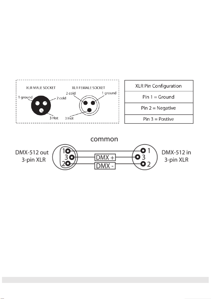
Your fixture and your DMX controller require a standard 3pin
connector for data input and data output. Also, remember that a
DMX line must be daisy chained and cannot be split.
NOTICE:
Page 9
www.oppray-light.com PL-W0124 12 x 8W Flat Par User Manual
Be sure to follow the diagrams below when making your own cables.
Do not connect the cables shield conductor to the ground lug or
allow the shield conductor to come in contact with the XLRs outer
casing. Grounding the shield could cause a short circuit and erratic
behavior.
DMX ADDRESSING
All fixtures should be given a DMX starting address when using a
DMX controller, so the correct fixture responds to the correct control
signal. This digital starting address is the channel number from
which the fixture starts to “listen” to the digital control information
sent out from the DMX controller. The allocation of this starting DMX
address is achieved by setting the correct DMX address on the
display located on the back of the fixture.
Page 10

www.oppray-light.com PL-W0124 12 x 8W Flat Par User Manual
You can set the same starting address for all fixtures or a group of
fixtures, or set different address for each individual fixture. Be
advised that setting all fixtures to the same DMX address will
subsequently control all fixtures in the same fashion, in other words,
changing the settings of one channel will affect all the fixtures
simultaneously.
If you set each fixture to a different DMX address, each unit will start
to “listen” to the channel number you have set, based on the
quantity of control channels (DMX channels) of each fixture. That
means changing the settings of one channel will only affect the
selected fixture.
In the case of the par light, when in the 9 Channel Mode you should
set the starting DMX address of the first unit to 1, the second unit to
10 (1 + 9), the third unit to 19 (10 + 9), and so on.
TECHNICAL SPECIFICATION
Electronic
Power supply: Electronic auto-ranging
Input voltage range: supply 100-240V, 50/60Hz
Power consumption 50W
Fuse T2.5A 250V
Light Sources
LED: 12 x 8W four-colour LEDs (RGBW)
LED life: 50000 hrs
Page 11
www.oppray-light.com PL-W0124 12 x 8W Flat Par User Manual
Packing
Packing Dimension: 175mm*175mm*62mm
Gross Weight: 1.8Kgs
Control
DMX Channel: 4/8 Channel
Control Modes: DMX512/Master-slave/Auto/IR remote Control
Construction
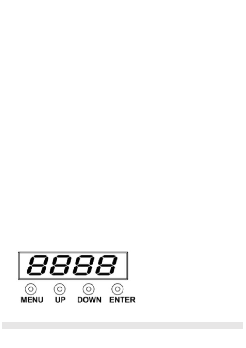
Display: 4 push button menu with LED display
Data In/Out socket: 3-pin XLR sockets
Bracket allows for multiple rigging or floor standing applications
Captive power connection
Approvals / Ratings
CE | IP20
Please Note: Specifications and improvements in the design of this unit and this manual are subject
to change without any prior written notice
CONTROL SYSTEM
DISPLAY:
Page 12

www.oppray-light.com PL-W0124 12 x 8W Flat Par User Manual
MENU To select the programming functions
UP To go forward in the selected functions
DOWN To go backward in the selected functions
ENTER To confirm the selected functions
FIXTURE MENU:
No.
Display
Function
1
d001
4 channel address code, (001-512)
B, C key to add and subtract address code values
2
E001
8 Channel address code, (001-512)
B, C key to add and subtract address code values
3
CC01
Colour jump to change, (01-99)
B, C key to modify jump to change speed
4
CP01
Gradient (01-99)
B, C key to modify the colors
5
dE01
Colour pulse variable, (01-99)
B and C modify pulse variable, velocity gradient
6
dENo
Jump, Gradient and pulse variable
7
bEbE
Sound control, Jump, Gradient and pulse variable
8
R255
Red colors, (000-255)
B, C key to modify the colors
9
G255
Green colors, (000-255)
B, C key to modify the colors
10
B255
Blue colors, (000-255)
B, C key to modify the colors
11
W255
White colors, (000-255)
B, C key to modify the colors
Page 13

www.oppray-light.com PL-W0124 12 x 8W Flat Par User Manual
OPERATING INSTRUCTION
DMX mode:
To select the DMX address, press the “MENU” button on the rear of
the unit to show d001 on the LED display. Now press the “ENTER”
button and use the “UP” and “DOWN” buttons to select the DMX
address between 000-512.
To exit out of any of the above options, press the “MENU” button.
DMX channel mode:
Operating in a DMX control mode environment gives the user the
greatest flexibility when it comes to customising or creating a show.
In this mode you will be able to control each individual trait of the
fixture and each fixture independently. To access the DMX channel
mode, press the “MENU” button on the rear of the unit to show 4CH or -8CH on the LED display. Now press the “ENTER” button
and use the“UP” and “DOWN” buttons to select between 4 and 8
channel.
To exit out of any of the above options, press the “MENU” button.
Colour change mode:
To access colour change mode press “MENU” until the display
shows CC-- on the LED display.Press “ENTER” to confirm the
setting. Use the “UP” and “DOWN” buttons to ajust the
speed between CC00 ~ CC99 . Press the “ENTER” button to
confirm the setting.To exit out of any of the above options, press the
“MENU” button.
Colour fade mode:
To access colour fade mode press “MENU” until the display
shows CP-- on the LED display.Press “ENTER” to confirm the
Page 14

www.oppray-light.com PL-W0124 12 x 8W Flat Par User Manual
setting. Use the “UP” and “DOWN” buttons to ajust the
speed between CP00 ~ CP99 . Press the “ENTER” button to
confirm the setting.To exit out of any of the above options, press the
“MENU” button.
Auto mode:
To access auto mode press “MENU” until the display shows dE-on the LED display.Press “ENTER” to confirm the setting. Use the
“UP” and “DOWN” buttons to ajust the speed between dE00 ~
dE99 . Press the “ENTER” button to confirm the setting.To exit out
of any of the above options, press the “MENU” button.
Static colour mode:
To access the static colour mode press “MENU” until r.225 shows
on the LED display.Now use the “UP” and “DOWN” buttons to select
the brightness between r.000 ~ r.255 . Press the“ENTER” button
and repeat for green ( G ), blue ( b ) and white ( u ).Value: 000 - 255
(000 = low brightness, 255 = high brightness) To exit out of any of
the above options, press the “MENU” button.
Master/slave mode:
To set the master unit, press the “MENU” button on the rear of the
master unit to select your desired program (sound active, auto, static
colour or colour fade).
To set the other units in slave mode, press the “MENU” button on
the rear of the unit to show d001on the LED display and press the
“ENTER” button to confirm the setting. The units will now run in
sequence with the master unit.
To exit out of any of the above options, press the “MENU” button.
Page 15
www.oppray-light.com PL-W0124 12 x 8W Flat Par User Manual
Please ensure that all slave units are set to the same DMX channel
mode as the master unit.
Sound active mode:
To access the sound active mode, press the “MODE” button on the
rear of the unit to show bEbE on the LED display. The unit will now
respond to sound.
To exit out of any of the above options, press the “MODE” button.
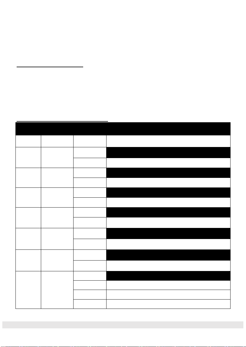
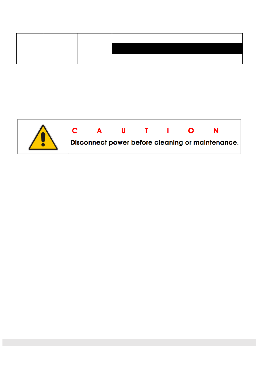
Channel Values / Functions
MODE/CHANNEL
VALUE
FUNCTION
8
6
1
1
RED
0-255
Red (0-Black, 255-100% Red)
2
2
GREEN
0-255
Green (0-Black, 255-100% Green)
3
3
BLUE
0-255
Blue (0-Black, 255-100% Blue)
4
4
WHITE
0-255
White (0-Black, 255-100% White)
5
DIMMER INTENSITY
0-255
Intensity 0 to 100%
6
STROBE
0-255
SLOW to FAST
7
FUNCTION CHOOSE
10-50
Manual DMX
51-100
Colour change
101-150
Colour fade
Page 16
www.oppray-light.com PL-W0124 12 x 8W Flat Par User Manual
151-200
Colour fade in/out
8
SPEED
0-255
Function speed (slow to fast)
CLEANING AND MAINTENANCE
CLEANING
Frequent cleaning is recommended to insure proper function,
optimized light output, and an extended life. The frequency of cleaning
depends on the environment in which the fixture operates: damp,
smoky or particularly dirty environments can cause greater
accumulation of dirt on the fixture’s optics.
• Clean the external lens surface at least every 20 days with a soft cloth to
avoid dirt/debris accumulation. Never use alcohol, solvents, or ammonia
based cleaners.
MAINTENANCE
Regular inspections are recommended to insure proper function and
extended life. There are no user serviceable parts inside this fixture,
please refer all other service issues to our service technician. Should
you need any spare parts, please order genuine parts from your
dealer.
Page 17

www.oppray-light.com PL-W0124 12 x 8W Flat Par User Manual
Please refer to the following points during routine inspections:
• A detailed electric check by an approved electrical engineer every 3
months, to make sure the circuit contacts are in good condition and prevent
overheating.
• Be sure all screws and fasteners are securely tightened at all times. Lose
screws may fall out during normal operation resulting in damage or injury.
• Check for any deformations on the housing, color lenses, rigging hardware
and rigging points (ceiling, suspension, trussing). Deformations in the
housing could allow for dust to enter into the fixture. Damaged rigging points
or unsecured rigging could cause the fixture to fall and seriously injure a
person(s).
• Inspect all moving parts and make sure there are no signs of wear and
rotate/move without imbalances.
• Electric power supply cables must not show any damage, material fatigue or
sediments. Never remove the ground prong from the power cable.
 Loading...