

Page 1
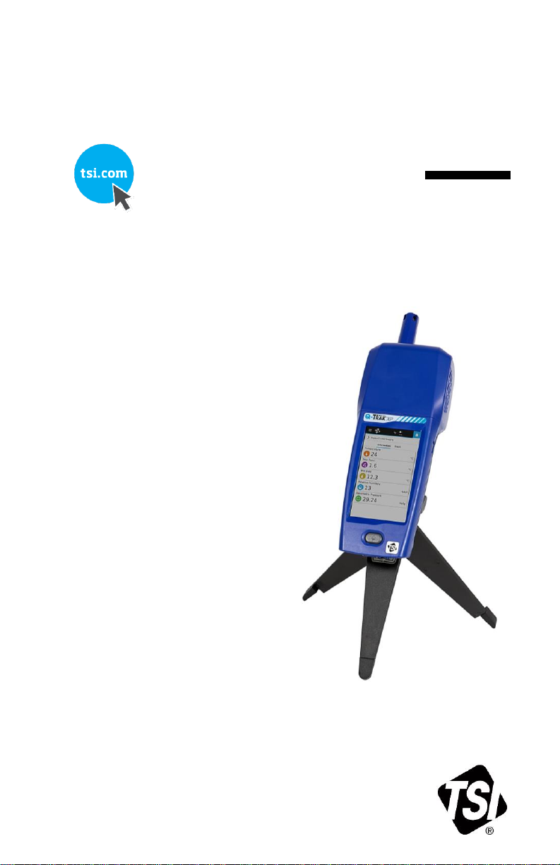
Q-TRAK™ XP
Shown with optional battery
cover with tripod mount and
tabletop tripod (P/N 800129)
INDOOR AIR QUALITY MONITOR
MODEL 7585
OPERATION AND SERVICE MANUAL
P/N 6013907, REVISION A
NOVEMBER 2020
Page 2
ii Q-Trak™ XP IAQ Monitor Model 7585
Page 3

Operation and Service Manual iii
Copyright©
TSI Incorporated / 2020 / All rights reserved.
Address
TSI Incorporated / 500 Cardigan Road / Shoreview, MN 55126 / USA
Fax No.
(651) 490-3824
Limitation of Warranty and Liability (effective February 2016)
(For country-specific terms and conditions outside of the USA, please visit www.tsi.com.)
Seller warrants the goods, excluding software, sold hereunder, under normal use and
service as described in the operator's manual, to be free from defects in workmanship
and material for 24 months, or if less, the length of time specified in the operator's
manual, from the date of shipment to the customer. This warranty period is inclusive of
any statutory warranty. This limited warranty is subject to the following exclusions and
exceptions:
a. The following gas sensors are warranted for 12 months from the date of shipment -
carbon dioxide, carbon monoxide, chlorine, hydrogen sulfide, nitric oxide, nitrogen
dioxide, ozone, and TVOC high and low sensors;
b. The following gas sensors are warranted for 6 months from the date of shipment -
ammonia and formaldehyde sensors;
c. Parts repaired or replaced as a result of repair services are warranted to be free
from defects in workmanship and material, under normal use, for 90 days from the
date of shipment;
d. Seller does not provide any warranty on finished goods manufactured by others or on
any fuses, batteries or other consumable materials. Only the original manufacturer's
warranty applies;
e. This warranty does not cover calibration requirements, and seller warrants only that
the instrument or product is properly calibrated at the time of its manufacture.
Instruments returned for calibration are not covered by this warranty;
f. This warranty is VOID if the instrument is opened by anyone other than a
factory authorized service center with the one exception where requirements
set forth in the manual allow an operator to replace consumables or perform
recommended cleaning;
g. This warranty is VOID if the product has been misused, neglected, subjected to
accidental or intentional damage, or is not properly installed, maintained, or cleaned
according to the requirements of the manual. Unless specifically authorized in a
separate writing by Seller, Seller makes no warranty with respect to, and shall have no
liability in connection with, goods which are incorporated into other products or
equipment, or which are modified by any person other than Seller.
The foregoing is IN LIEU OF all other warranties and is subject to the LIMITATIONS
stated herein. NO OTHER EXPRESS OR IMPLIED WARRANTY OF FITNESS FOR
PARTICULAR PURPOSE OR MERCHANTABILITY IS MADE. WITH RESPECT TO
SELLER’S BREACH OF THE IMPLIED WARRANTY AGAINST INFRINGEMENT,
SAID WARRANTY IS LIMITED TO CLAIMS OF DIRECT INFRINGEMENT AND
EXCLUDES CLAIMS OF CONTRIBUTORY OR INDUCED INFRINGEMENTS.
BUYER’S EXCLUSIVE REMEDY SHALL BE THE RETURN OF THE PURCHASE
PRICE DISCOUNTED FOR REASONABLE WEAR AND TEAR OR AT SELLER’S
OPTION REPLACEMENT OF THE GOODS WITH NON-INFRINGING GOODS.
TO THE EXTENT PERMITTED BY LAW, THE EXCLUSIVE REMEDY OF THE USER
OR BUYER, AND THE LIMIT OF SELLER'S LIABILITY FOR ANY AND ALL LOSSES,
INJURIES, OR DAMAGES CONCERNING THE GOODS (INCLUDING CLAIMS
BASED ON CONTRACT, NEGLIGENCE, TORT, STRICT LIABILITY OR
OTHERWISE) SHALL BE THE RETURN OF GOODS TO SELLER AND THE
REFUND OF THE PURCHASE PRICE, OR, AT THE OPTION OF SELLER, THE
Page 4

iv Q-Trak™ XP IAQ Monitor Model 7585
REPAIR OR REPLACEMENT OF THE GOODS. IN THE CASE OF SOFTWARE,
SELLER WILL REPAIR OR REPLACE DEFECTIVE SOFTWARE OR IF UNABLE TO
DO SO, WILL REFUND THE PURCHASE PRICE OF THE SOFTWARE. IN NO
EVENT SHALL SELLER BE LIABLE FOR LOST PROFITS, BUSINESS
INTERRUPTION, OR ANY SPECIAL, INDIRECT, CONSEQUENTIAL OR
INCIDENTAL DAMAGES. SELLER SHALL NOT BE RESPONSIBLE FOR
INSTALLATION, DISMANTLING OR REINSTALLATION COSTS OR CHARGES. No
Action, regardless of form, may be brought against Seller more than 12 months after a
cause of action has accrued. The goods returned under warranty to Seller's factory
shall be at Buyer's risk of loss, and will be returned, if at all, at Seller's risk of loss.
Buyer and all users are deemed to have accepted this LIMITATION OF WARRANTY
AND LIABILITY, which contains the complete and exclusive limited warranty of Seller.
This LIMITATION OF WARRANTY AND LIABILITY may not be amended, modified or
its terms waived, except by writing signed by an Officer of Seller.
Service Policy
Knowing that inoperative or defective instruments are as detrimental to TSI as they are
to our customers, our service policy is designed to give prompt attention to any
problems. If any malfunction is discovered, please contact your nearest sales office or
representative, or call Customer Service department at (800) 680-1220 (USA) or
(1) 651-490-2860 (International).
Trademarks
TSI and TSI logo are registered trademarks of TSI Incorporated in the United States
and may be protected under other country’s trademark registrations. Q-Trak and
TrakPro are trademarks of TSI Incorporated. Wi-Fi is a registered trademark of the
Wi-Fi Alliance.
Page 5

v
CONTENTS
CONTENTS ......................................................................................... V
SAFETY .............................................................................................. IX
Description of Caution/Warning Symbols ........................................ ix
Caution ......................................................................................... ix
Warning ........................................................................................ ix
Caution and Warning Symbols ......................................................... x
Battery Safety and Disposal ............................................................. x
Laser Safety ..................................................................................... xi
Labels .............................................................................................. xii
Reusing and Recycling ...................................................................xiv
CHAPTER 1 OVERVIEW ................................................................... 1
CHAPTER 2 UNPACKING AND PARTS IDENTIFICATION ............. 3
Standard Equipment ......................................................................... 3
Optional Gas Sensors ....................................................................... 5
Optional Accessories ........................................................................ 6
Other Replacement Parts ................................................................. 6
CHAPTER 3 SETTING UP THE Q-TRAK™ XP MONITOR ............... 9
Installation of Gas Sensors ............................................................... 9
Providing Power to the Q-Trak™ XP .............................................. 10
Operating the Instrument with the AC Adapter ........................... 10
Operating the Instrument with the Lithium-Ion Battery ................ 11
Charging the Battery and Calibrating the Power Gauge ............. 12
Installing and Connecting to Available Wi-Fi® (optional
Wi-Fi® dongle ............................................................................... 13
Connecting to a Computer and Installing TrakPro™
Ultra Software .............................................................................. 13
CHAPTER 4 OPERATIONAL OVERVIEW ...................................... 15
Powering ON the Q-Trak™ XP Monitor .......................................... 15
Navigating the Dashboard Page+ .................................................. 17
Main Menu ...................................................................................... 18
Dashboard ................................................................................... 19
Settings ........................................................................................ 19
Manage Data ............................................................................... 20
Calibration ................................................................................... 20
Workflows .................................................................................... 21
Device Information ....................................................................... 22
Page 6

vi Q-Trak™ XP IAQ Monitor Model 7585
CHAPTER 5 SETTINGS ................................................................... 23
General Settings ............................................................................. 24
Date/Time ....................................................................................... 25
Display/Power Management ........................................................... 26
Sensors ........................................................................................... 27
Network Settings ............................................................................. 28
Units of Measure ............................................................................. 29
Notifications/Alarms ........................................................................ 30
CHAPTER 6 CALIBRATION ............................................................ 31
Gas Sensors ................................................................................... 31
Gas Sensor Verification .................................................................. 31
Gas Calibration Procedure.............................................................. 33
Step 1 – Select a Gas Sensor for Calibration .............................. 33
Step 2 – Place the calibration cap onto the gas sensor
you want to calibrate ................................................................ 34
Step 3 - Select the sensor to be calibrated on the
instrument display .................................................................... 34
Step 4 - Perform ZERO Capture ................................................. 35
Step 5 – Perform SPAN Capture ................................................. 35
Step 6 – Save or Discard Calibration .......................................... 36
Gas Calibration Unsuccessful ..................................................... 37
Built-in Sensor Calibration: Temperature, Relative Humidity,
and Barometric Pressure Sensors ............................................... 37
Reset Sensors to Default Calibration .............................................. 39
CHAPTER 7 LOGGING DATA ......................................................... 41
Logging Data ................................................................................... 42
Logging Profiles .............................................................................. 43
Locations ......................................................................................... 43
Settings ........................................................................................... 45
Logging Mode .............................................................................. 45
Sample Interval ............................................................................ 46
Schedules ....................................................................................... 46
CHAPTER 8 MANAGE DATA .......................................................... 49
Selecting Log Files .......................................................................... 49
View Log Files ................................................................................. 50
Delete Log Files .............................................................................. 50
Export Log Files .............................................................................. 51
Edit Log File Names ........................................................................ 52
Scrolling Through Data List ......................................................... 52
CHAPTER 9 WORKFLOWS ............................................................ 53
Percent Outside Air (%OA) Calculation Procedure ........................ 53
Page 7

Operation and Service Manual vii
CHAPTER 10 TRAKPRO™ ULTRA SOFTWARE ........................... 57
CHAPTER 11 UPDATE INSTRUMENT SOFTWARE ..................... 59
CHAPTER 12 MAINTENANCE ........................................................ 61
Replacing Sensors .......................................................................... 61
Recalibration ................................................................................... 61
Removing the Sensor Module from the Handle of the
Q-Trak™ XP Monitor. ................................................................... 61
Storage ........................................................................................... 63
CHAPTER 13 TROUBLESHOOTING .............................................. 65
Error Messages .............................................................................. 68
CHAPTER 14 HELP .......................................................................... 71
TSI® Technical Support/Service ...................................................... 71
APPENDIX A SPECIFICATIONS ..................................................... 73
APPENDIX B DEFINITIONS ............................................................. 77
Page 8

viii Q-Trak™ XP IAQ Monitor Model 7585
(This page intentionally left blank)
Page 9
ix
Safety
This section provides instructions to ensure safe and proper
operation of the Q-Trak™ XP Indoor Air Quality Monitor Model 7585.
WARNING
• The instrument must be used in the manner
described in this manual. Failure to follow all of the
procedures described in this manual can result in
serious injury to you or can cause irrevocable
damage to the instrument.
• There are no user-serviceable parts inside the
instrument. Refer all repairs to a qualified factoryauthorized technician.
• The Q-Trak™ XP monitor is not rated for intrinsic
safety. DO NOT operate the Q-Trak™ XP monitor
under conditions where there is a risk of fire or
explosion.
Description of Caution/Warning Symbols
Appropriate caution/warning statements are used throughout the
manual and on the instrument that require you to take cautionary
measures when working with the instrument.
Caution
CAUTION
Failure to follow the procedures prescribed in this
manual might result in irreparable equipment damage.
Important information about the operation and
maintenance of this instrument is included in
this manual.
Warning
WARNING
Warning means that unsafe use of the instrument
could result in serious injury to you or cause damage
to the instrument. Follow the procedures prescribed.
Page 10
x Q-Trak™ XP IAQ Monitor Model 7585
Caution and Warning Symbols
The following symbols may accompany cautions and warnings to
indicate the nature and consequences of hazards:
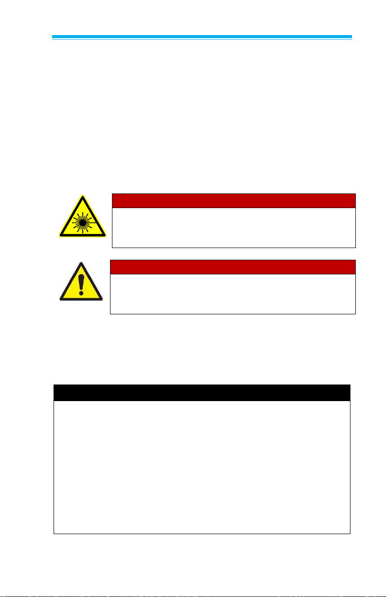
Warns that the instrument contains a laser and that
important information about its safe operation and
maintenance is included in the manual.
Warns that the instrument is susceptible to electrostatic discharge (ESD) and ESD protection should be
followed to avoid damage.
Indicates the connector is connected to earth ground
and cabinet ground.
Battery Safety and Disposal
This instrument uses a rechargeable Lithium ion battery with built-in
protection against safety hazards. Always dispose of Li-ion
batteries and transport Li-ion batteries in compliance with
regional regulations.
WARNING
• Use only TSI® supplied batteries in this instrument
(P/N 800123).
• DO NOT abuse the battery in any way as the
battery may rupture or catch fire.
• DO NOT use a substitute or non-rechargeable
battery in this instrument.
• DO NOT short-circuit, incinerate, dismantle or
mutilate Lithium ion batteries.
• DO NOT expose to water or heat.
• DO NOT use any battery which shows signs of
damage, such as bulging, swelling, a swollen
plastic wrap, liquid in the plastic wrap, etc.
Page 11
Operation and Service Manual xi
Laser Safety
The Q-Trak™ XP Model 7585 is a Class I laser-based instrument.
During normal operation, the user WILL NOT be exposed to
laser radiation.
The following precautions should be taken to avoid exposure to
hazardous radiation in the form of intense, focused, visible light.
• DO NOT remove any parts from the Q-Trak™ XP monitor unless
you are specifically told to do so in this manual.
• DO NOT disassemble the Q-Trak™ XP monitor. There are no
user-serviceable components inside the instrument.
WARNING
The use of controls, adjustments, or procedures
other than those specified in this manual may result
in exposure to hazardous optical radiation.
WARNING
If the Q-Trak™ XP monitor is used in a manner not
specified by the manufacturer, the protection
provided by the equipment may be impaired.
When operated according to the manufacturer’s instruction, this
device is a Class 1 laser product as defined by U.S. Department of
Health and Human Services standards under the Radiation Control
for Health and Safety Act of 1968.
D I S C L A I M E R
The CO2 measurement sensor is sensitive to radio frequency
interference. Electromagnetic fields produced by items including,
but not limited to, microwave ovens, Wi-Fi® routers, cellular
phones, and personal communication devices, i.e., walkie-talkie,
two-way radios, etc. have the potential to adversely affect the CO2
measurement. To ensure a proper measurement these devices
should be TURNED OFF or placed in a mode that does not
transmit. If these devices are not turned off or placed in a mode
that does not transmit, the accuracy of the CO2 measurement may
be compromised if these devices are located within four meters of
the CO2 measurement sensor.
Page 12
xii Q-Trak™ XP IAQ Monitor Model 7585
Labels
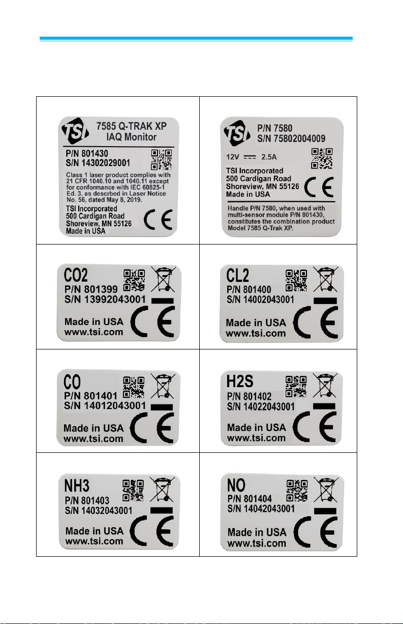
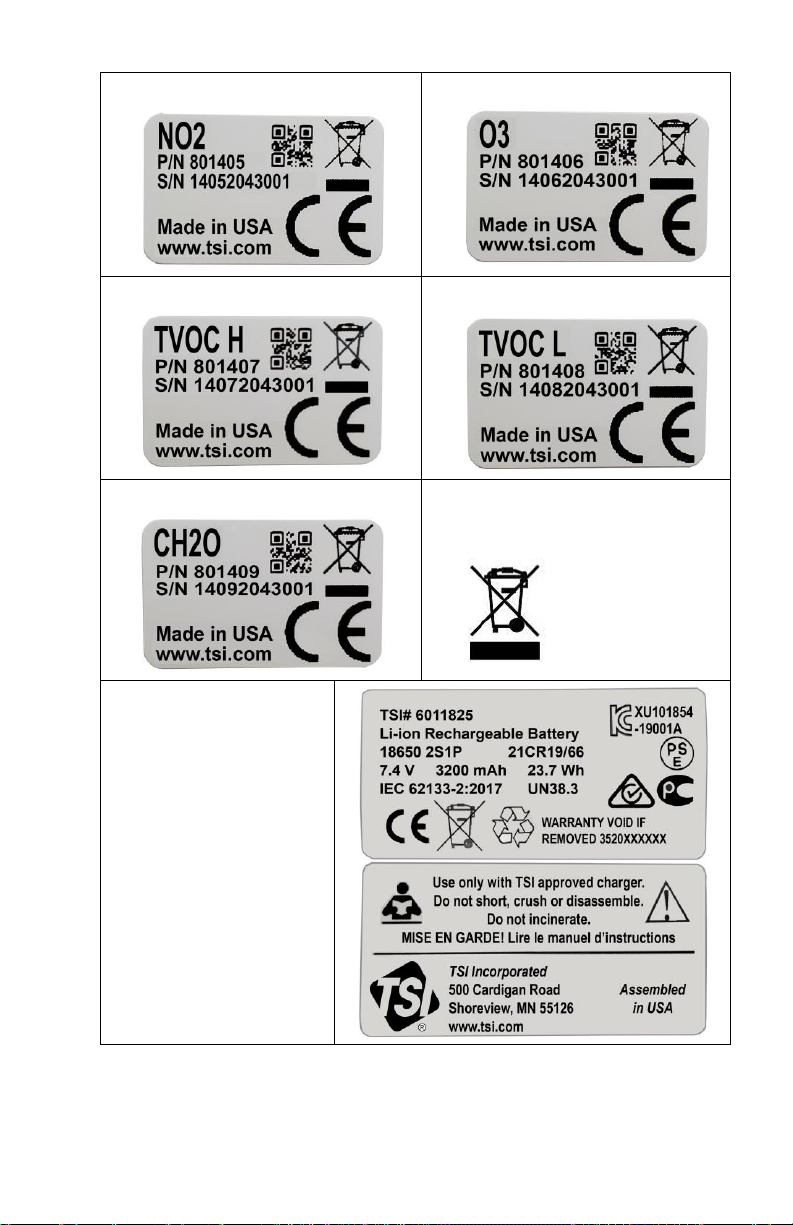
Advisory and identification labels or markings are attached to
the instrument.
1. Multi-sensor module
2. Base handle
3. Carbon Dioxide sensor
4. Chlorine sensor
5. Carbon Monoxide sensor
6. Hydrogen Sulfide sensor
7. Ammonia sensor
8. Nitric Oxide sensor
Page 13
Operation and Service Manual xiii
9. Nitrogen Dioxide sensor
10. Ozone sensor
11. TVOC ppm sensor
12. TVOC ppb sensor
13. Formaldehyde sensor
14. European symbol for nondisposable item. Item must be
recycled.
15. Battery pack
Page 14

xiv Q-Trak™ XP IAQ Monitor Model 7585
Reusing and Recycling
As part of TSI® Incorporated’s effort to have a
minimal negative impact on the communities in
which its products are manufactured and used:
DO NOT dispose of use batteries in the trash.
Follow local environmental requirements for
battery recycling.
If instrument becomes obsolete, return to TSI®
for disassembly and recycling.
Page 15

1
CHAPTER 1
Overview
The Q-Trak™ XP Indoor Air Quality (IAQ) Monitor is designed for
Indoor Air Quality and Industrial Hygiene professionals to address
a wide range of indoor air quality assessments and analysis. The
Q-Trak™ XP monitor combines multiple-gas and particle
measurements into a single lightweight, handheld instrument that
is easy to configure, maintain, and calibrate in the field. The
Model 7585 includes sensors for simultaneous measurements of
temperature, relative humidity, barometric pressure, mass
concentration, particle concentration, carbon dioxide, and room for
up to five additional pluggable gas sensors. With enough on-board
memory to record data from all sensors for 30 days when sampling
data once a minute.
Also included with the Q-Trak™ XP monitor is TrakPro™ Ultra
software application used for posttest analysis and report
generation. Refer to Chapter 10 for more information.
These Application Notes for the Q-Trak™ can be found under TSI’s
web site at www.tsi.com/7585.
Page 16

2 Q-Trak™ XP IAQ Monitor Model 7585
(This page intentionally left blank)
Page 17
3
CHAPTER 2
Unpacking and Parts Identification
Carefully unpack the instrument and accessories from the shipping
container. Check the individual parts against the list of components
below. If anything is missing or damaged, notify TSI® immediately.
All standard equipment can be purchased separately if needed.
NOTE
Optional gas sensors are shipped in individual boxes but are
included in the main shipping container.
NOTE
The lithium-ion battery is shipped in the same box as the
instrument; however, it cannot be pre-installed in the Q-Trak™ XP
instrument prior to shipment as required by law.
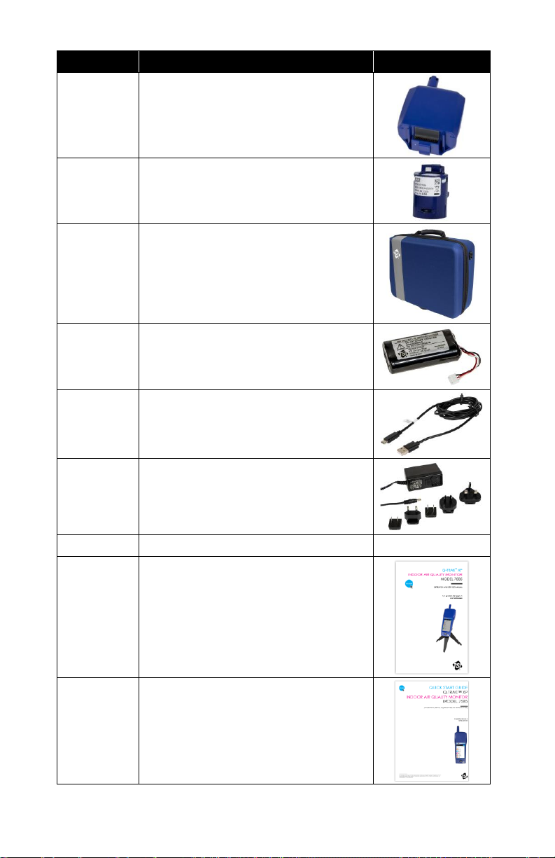
Standard Equipment
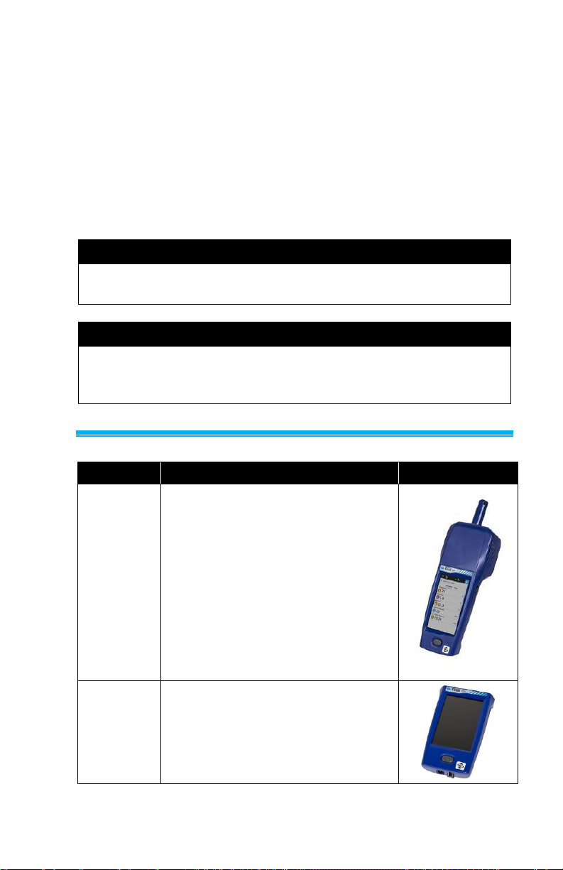
Part No.
Description
Picture
7585
Includes Q-Trak™ XP Base Meter with
Multi-Sensor IAQ Module and the
following sensors:
• PM 2.5 sensor
• Temperature and Relative
Humidity sensor
• Barometric Pressure sensor*
• Carbon Dioxide (CO2) sensor
(801399)
IAQ module includes six configurable
gas sensor slots
7580
Base Meter only – Handle portion
Page 18
4 Q-Trak™ XP IAQ Monitor Model 7585
Part No.
Description
Picture
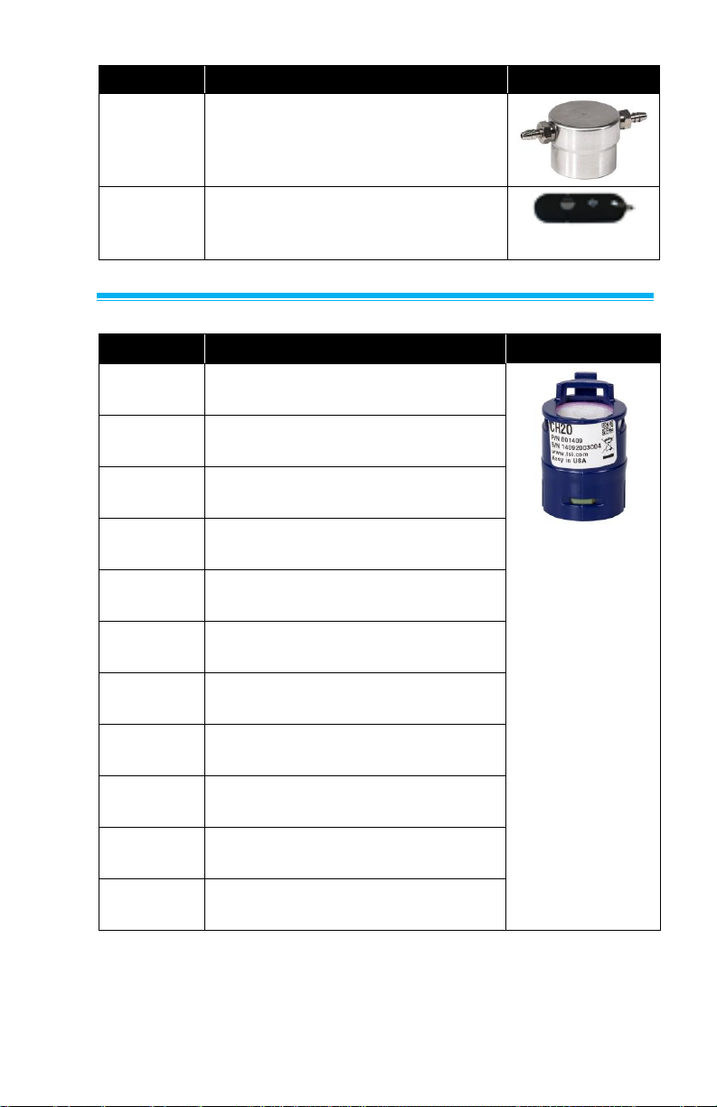
801430*
IAQ Multi-Sensor Gas Module with
Built-in Sensors: Temperature,
Relative Humidity, Barometric
Pressure, Particle
801399
CO2 (Carbon Dioxide), NDIR
(Nondispersive Infrared sensor)
800121
Carrying Case
800123
Lithium Ion Rechargeable
Battery Pack
804001
USB Cable
800122
AC Adapter/Power Supply
N/A
Calibration certificates
N/A
6013907
Q-Trak™ XP User Manual (English:
Included on USB drive)
6013908
Q-Trak™ XP Quick Start Guide
(includes French, German, Simplified
Chinese, and Traditional Chinese)
Page 19
Operation and Service Manual 5
Part No.
Description
Picture
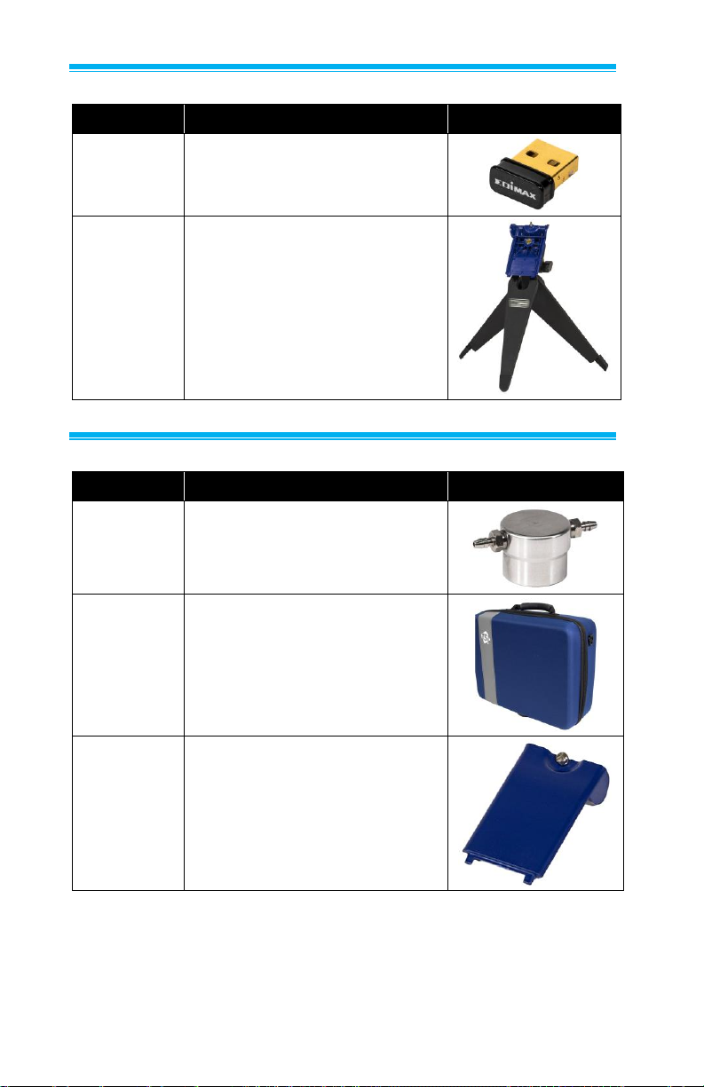
800120
Gas Sensor Calibration Cap
7004280
USB Flash Drive with Q-Trak™ XP
manuals and other literature. Included
with 7585.
Optional Gas Sensors
Part No.
Description
Picture
801399
CO2 (Carbon Dioxide), NDIR
(Nondispersive Infrared sensor)
(801403)
801400
Cl2 (Chlorine), EC (Electrochemical
Sensor)
801401
CO (Carbon Monoxide), EC
(Electrochemical Sensor)
801402
H2S (Hydrogen Sulfide), EC
(Electrochemical Sensor)
801403
NH3 (Ammonia), EC (Electrochemical
Sensor)
801404
NO (Nitric Oxide), EC (Electrochemical
Sensor)
801405
NO2 (Nitrogen Dioxide), EC
(Electrochemical Sensor)
801406
O3 (Ozone), EC (Electrochemical
Sensor)
801407
TVOCH (VOC ppm), PID
(Photoionization Detection Sensor)
801408
TVOCL (VOC ppb), PID
(Photoionization Detection Sensor)
801409
CH2O (Formaldehyde), EC
(Electrochemical Sensor)
Page 20
6 Q-Trak™ XP IAQ Monitor Model 7585
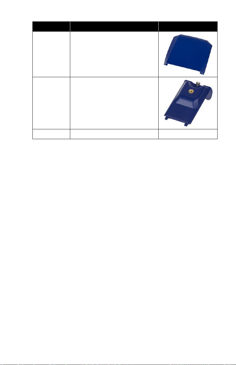
Optional Accessories
Part No.
Description
Picture
800124
Wi-Fi® dongle
800129
Q-Trak™ XP Battery Cover with
Tripod Mount and Tabletop Tripod
Other Replacement Parts
Part No.
Description
Picture
800120
Q-Trak™ XP Gas Sensor
calibration cap
800121
Q-Trak™ XP Case: hard sided
carry case
800126
Battery Cover
Page 21
Operation and Service Manual 7
Part No.
Description
Picture
800127
Sensor Module Cover
800125
Battery cover with tripod mount
800128
Tabletop Tripod
N/A
Page 22

8 Q-Trak™ XP IAQ Monitor Model 7585
(This page intentionally left blank)
Page 23
9
CHAPTER 3
Setting Up the Q-Trak™ XP Monitor
Installation of Gas Sensors
In addition to the standard built-in sensors, the device can accept up
to six gas sensors.
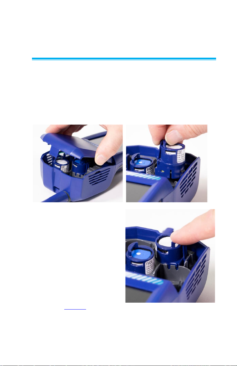
Install the gas sensors as follows:
1. Ensure the instrument is powered OFF.
2. Remove the sensor module cover.
3. Position the sensor as
shown, making certain the
pins make good contact
with the device. Gas
sensors can be installed in
any available slot. Listen for
a click to confirm sensor is
connected properly.
4. Attach cover to the sensor
module.
5. To configure which sensors
are shown on the display,
refer to Sensors section in
Chapter 5.
Page 24
10 Q-Trak™ XP IAQ Monitor Model 7585
Providing Power to the Q-Tra k™ XP
The Q-Trak™ XP monitor can be powered with provided lithium-ion
battery or with the provided A/C adapter.
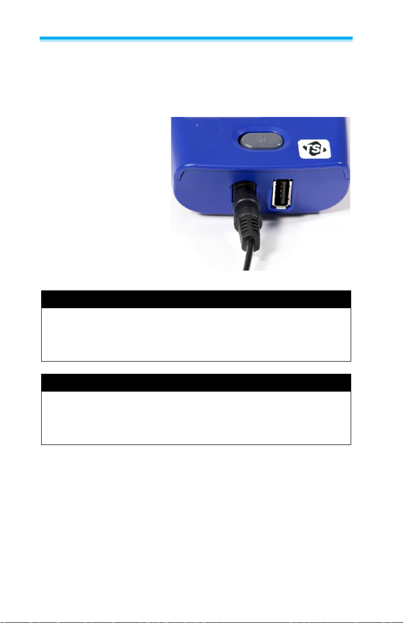
Operating the Instrument with the AC Adapter
The instrument can be
operated with or without
a battery using the
A/C adapter.
To operate the instrument
with AC adapter:
1. Plug the AC adapter
into an electrical
outlet.
2. Plug the other end
into the instrument.
NOTE
In general, TSI® recommends operating the Q-Trak™ XP monitor
with a battery even when powering the instrument with an AC
power supply. Having a battery installed shortens the warm-up
time needed for sensors to make accurate measurements.
NOTE
For best results, power on the instrument for 10 minutes before
verifying gas sensor performance. This allows the instrument and
sensors to thermally stabilize and reduces the amount of
measurement drift during verification or calibration.
Page 25
Operation and Service Manual 11
Operating the Instrument with the Lithium-Ion Battery
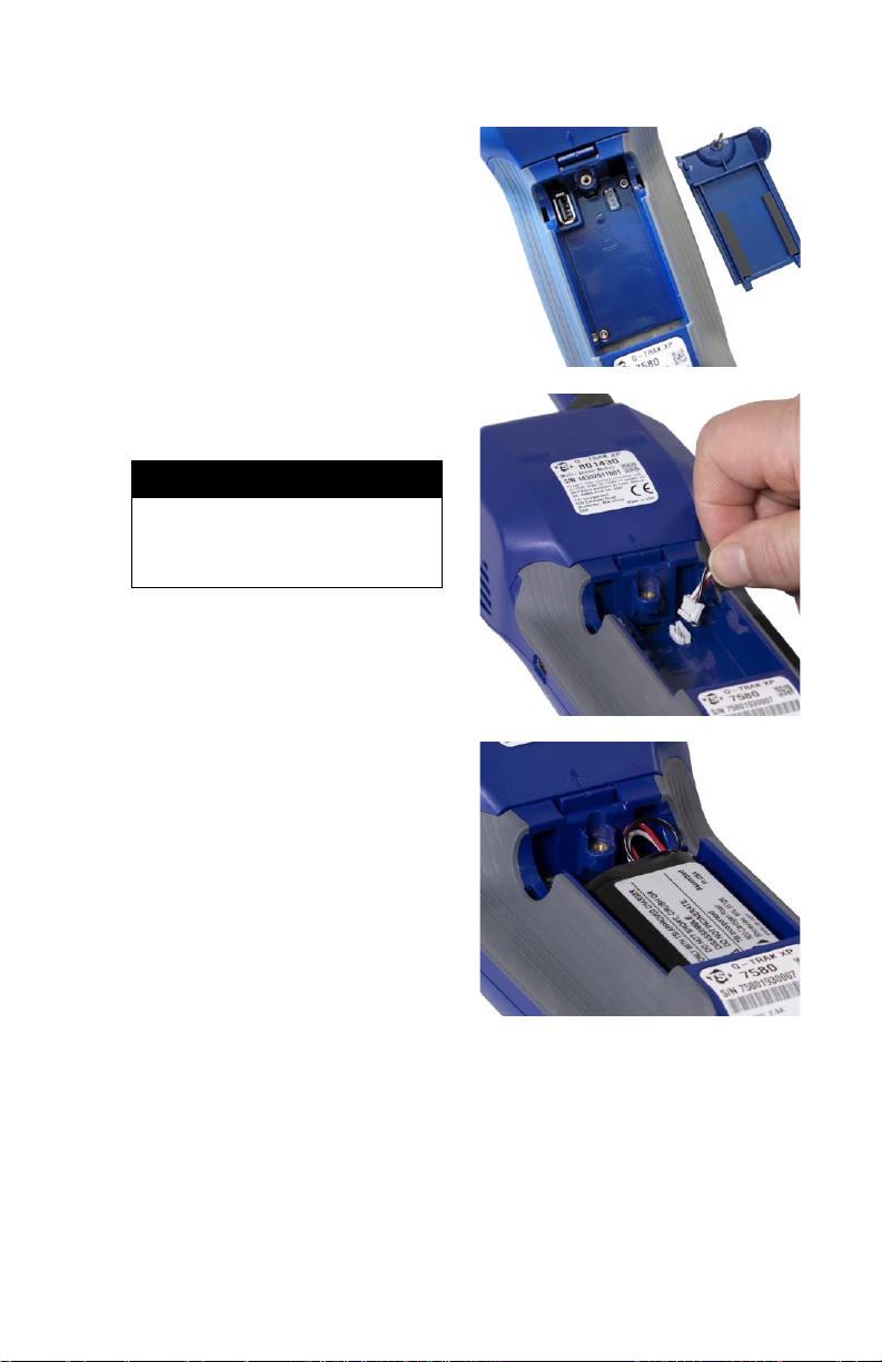
To install the battery:
1. Remove the battery
compartment cover.
2. Connect the battery to the
handle connector.
NOTE
The battery pack connector
is designed to prevent
improper connection.
3. Insert the battery as
shown in the picture,
keeping the battery wires
to the side and clear of
the battery cover screw.
Page 26
12 Q-Trak™ XP IAQ Monitor Model 7585
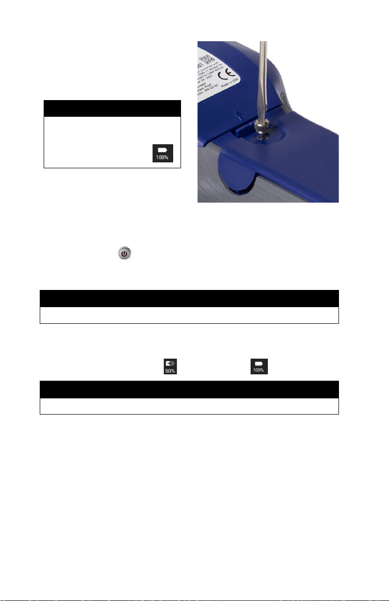
4. Attach the battery
compartment cover,
ensuring battery wires
are clear of the screw.
IMPORTANT
Always calibrate the battery
Power Gauge after installing
a battery pack.
Charging the Battery and Calibrating the Power Gauge
1. With the battery installed, turn on the instrument by pressing the
power button and run until the battery is fully discharged.
The instrument will automatically turn off when the battery is fully
discharged.
NOTE
The battery is shipped with approximately 25% to 30% charge.
2. Connect the AC adapter to the instrument and fully charge the
battery. This may take up to 3 hours. Note the lightning bolt
indicator when charging vs fully charged .
NOTE
It is normal for the battery to feel warm as it is charging.
3. The instrument is now ready for use with the battery. This Power
Gauge calibration procedure does not need to be repeated
unless the battery is replaced or disconnected.
Page 27
Operation and Service Manual 13
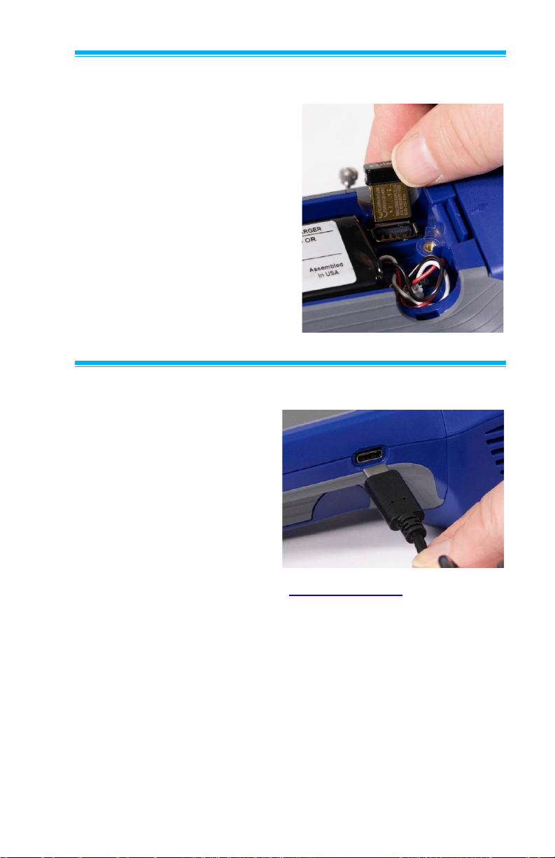
Installing and Connecting to Available Wi-Fi®
(optional Wi-Fi® dongle
To connect your device to
a Wi-Fi® network, proceed
as follows:
1. Install the dongle into the
USB port located inside
the battery compartment.
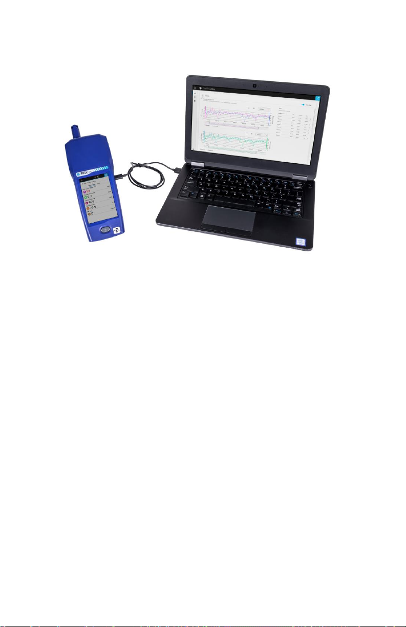
Connecting to a Computer and Installing Tra kPro™ Ultra Software
To connect the Q-Trak™ XP
monitor to a computer for
downloading data files or
when using the TrakPro™
Ultra Software application:
1. Connect the USB-C
cable provided with the
Q-Trak™ XP monitor to
a computer.
2. From a computer, navigate to www.tsi.com/7585 and select the
TrakPro™ Ultra application exe.
3. Download and install the application.
4. Launch the TrakPro™ Ultra application.
Page 28
14 Q-Trak™ XP IAQ Monitor Model 7585
5. Refer to of the user guide in “help” menu within TrakPro™ Ultra
software for operation information.
Page 29
15
CHAPTER 4
Operational Overview
Powering ON the Q-Trak™ XP Monitor
Press and release the power
button . A progress bar will
appear as the instrument boots.
To power down the instrument,
press the power button and
press shutdown from the
pop-up screen
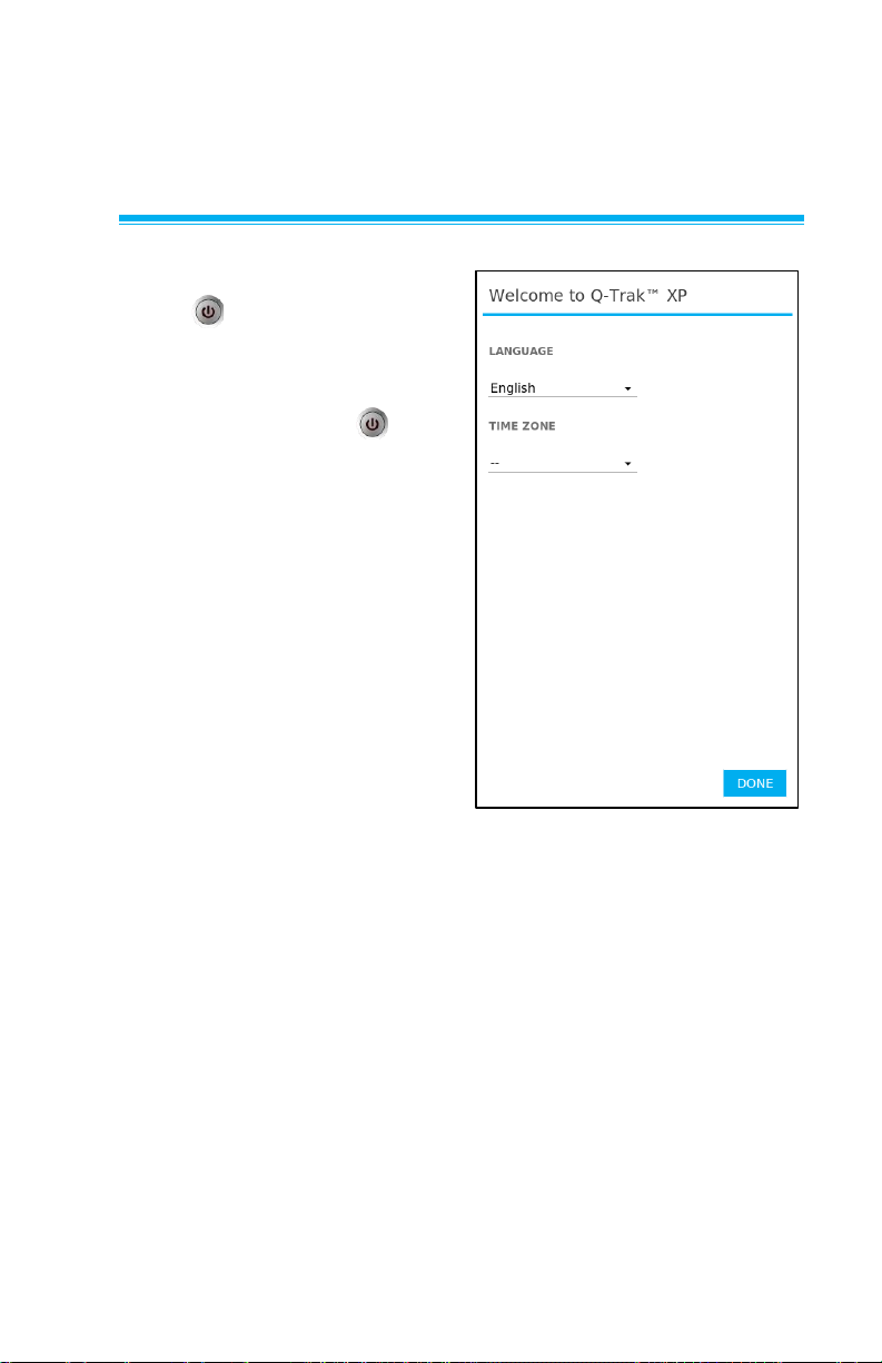
The first time the Q-Trak XP
monitor is powered ON the
Welcome to Q-TrakTM XP
page is presented. Select the
appropriate Language and
Time Zone then select DONE.
After selecting DONE the
Dashboard page is displayed
in Survey mode.
Page 30
16 Q-Trak™ XP IAQ Monitor Model 7585
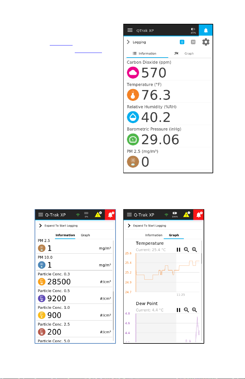
Survey mode displays real-time
readings of sensors selected
from the Sensors page
discussed later in Chapter 5. It
does not log measurements
or statistics.
Selecting Graph presents real-time readings in a graphical format
while selecting Information present data in a numerical format. To
view sensors not shown on the page, swipe up and down.
Page 31
Operation and Service Manual 17
NOTE
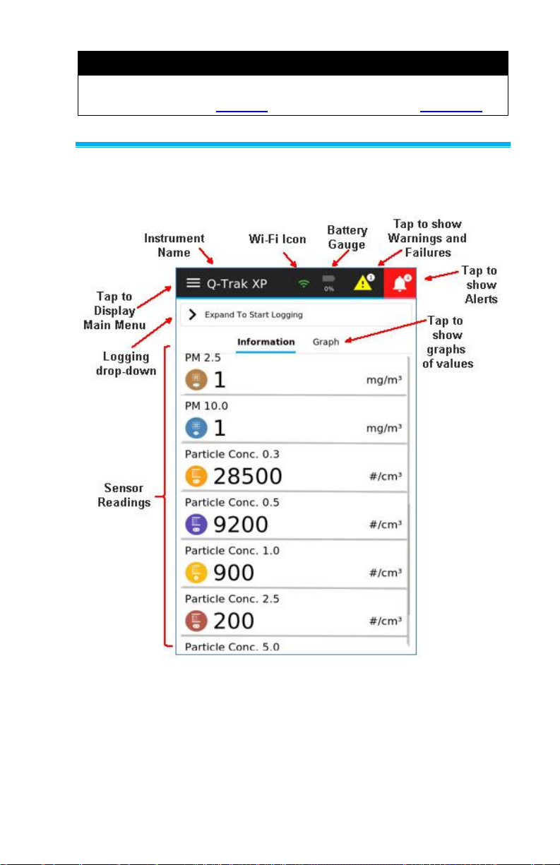
Sensors will only appear in the Dashboard page once they have
been selected in the Sensors page discussed later in Chapter 5.
Navigating the Dashboard Page+
The following Dashboard diagram dissects the layout of the
Dashboard page.
Page 32
18 Q-Trak™ XP IAQ Monitor Model 7585
Main Menu
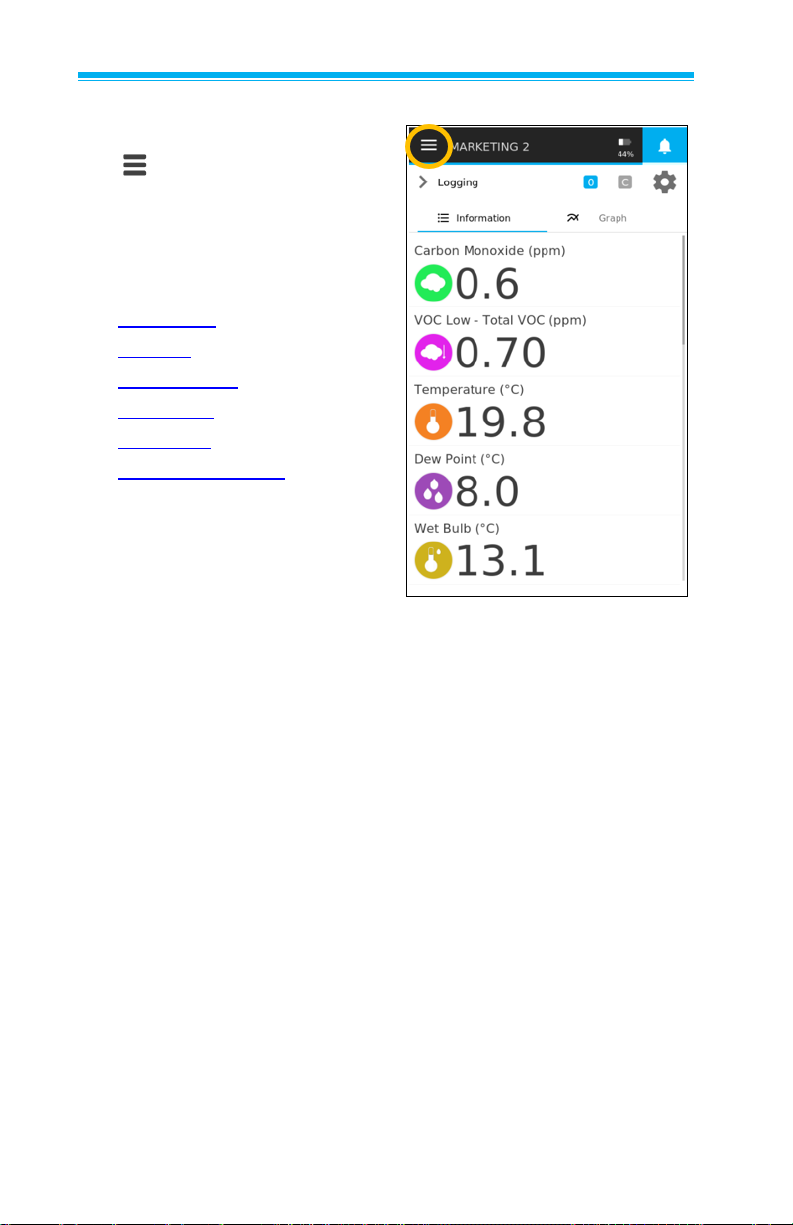
To display the Main Menu, select
the icon in the upper left
corner of the header on any page
of the display.
The Main Menu has seven
options:
• Dashboard
• Settings
• Manage Data
• Calibration
• Workflows
• Device Information
• Help
Page 33
Operation and Service Manual 19
Dashboard
This is the main page for viewing
live readings, live graphs and
logging data.
Select Dashboard from the
menu in the header any time
to return to the Dashboard
(Home) page.
Settings
Select Settings from the
Main Menu, to view the
Settings page options. Refer to
Chapter 5, Settings for detailed
information about the device
setting options.
Page 34
20 Q-Trak™ XP IAQ Monitor Model 7585
Manage Data
Select Manage Data to display
logged data stored in the device.
Refer to Chapter 8, Manage
Data for detailed information.
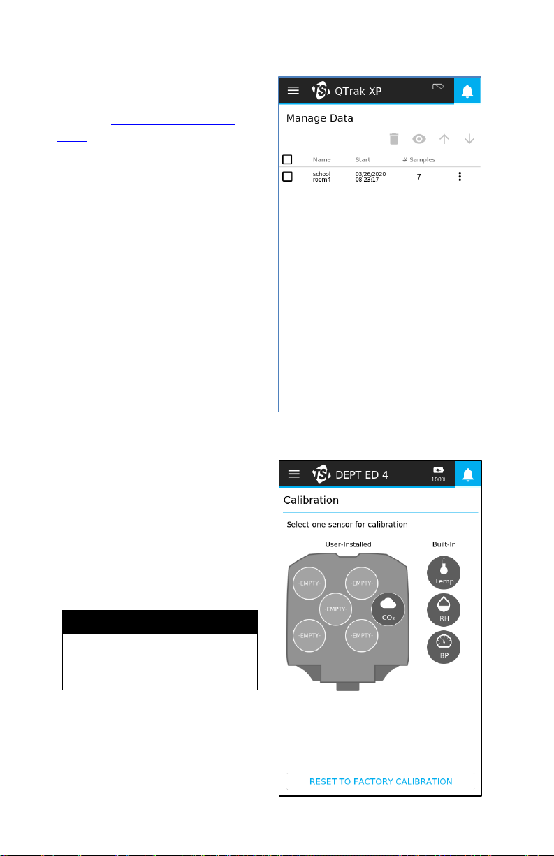
Calibration
Sensors are calibrated before
they are shipped from TSI. If a
sensor requires a field
calibration, select Calibration
from the Main Menu. The
Calibration page presents the
sensors (except the particle
sensor) installed in the device.
NOTE
A user calibration cannot be
applied to particle
measurements.
Page 35
Operation and Service Manual 21
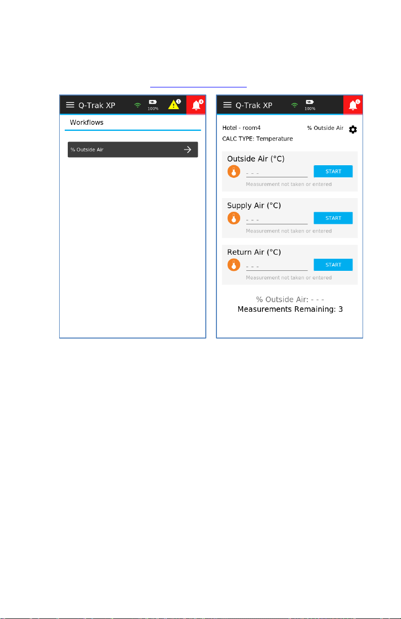
Workflows Percent of Outside Air: Select Workflows from the Main Menu,
and then % Outside Air to begin performing a % Outside Air
Calculation. Refer to Chapter 9, Workflows for details.
Page 36
22 Q-Trak™ XP IAQ Monitor Model 7585
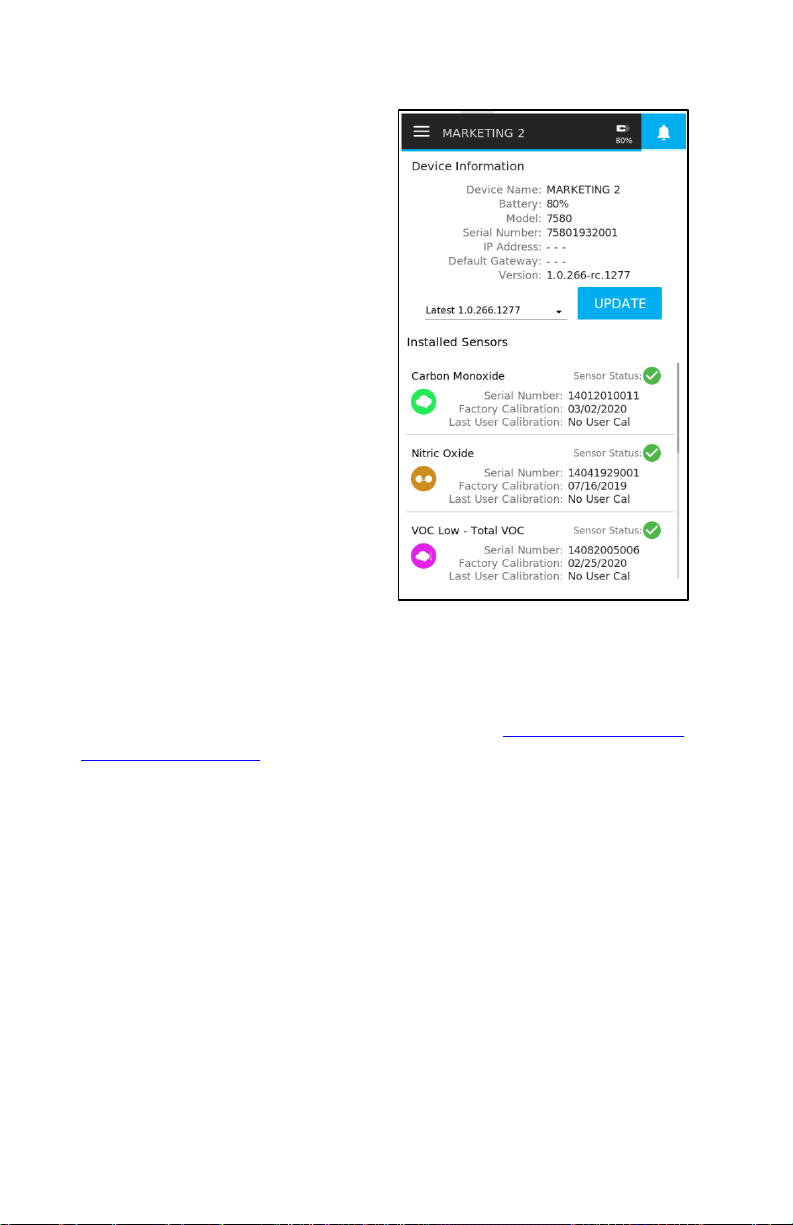
Device Information
To display general information
about the Q-Trak™ XP monitor,
select Device Information from
the Main Menu. The Device
Information page lists the
device name, IP address, model
number, and many other
characteristics of the device as
well as information about the
installed sensors.
To view sensors not shown on
the page, swipe up and down.
This information is important for
troubleshooting issues related to
the operation of the device.
Furthermore, the Device
Information page includes the
ability to update the software
version for the Q-Trak™ XP
monitor from a flash drive or
computer.
To update the Q-Trak™ XP monitor software, select the down arrow
from the Device Information page and select the latest software
version then select the Update button. Refer to Chapter 11, Update
Instrument Software for more information.
Page 37
23
CHAPTER 5
Settings
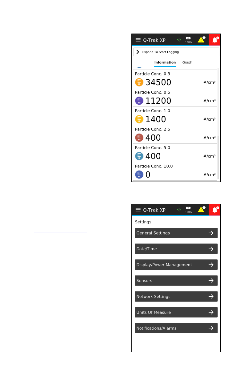
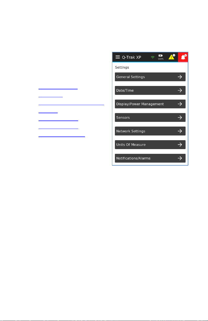
Navigate to the Settings page
by selecting Settings from the
Main Menu.
The Settings page options are:
• General Settings
• Date/Time
• Display/Power Management
• Sensors
• Network Settings
• Units of Measure
• Notifications/Alarms
These options are described in
the following subsections.
Page 38
24 Q-Trak™ XP IAQ Monitor Model 7585
General Settings
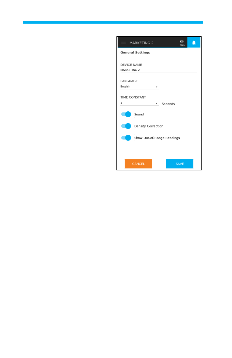
The General Settings page is
used to configure the following
functions:
• Device Name is used to
customize the name of the
instrument. This feature is
helpful when associating
data to a specific instrument.
NOTE: The device will
display up to 14 characters
of the device name in the
header of the main
Dashboard page.
• Language is used to select
the desired language shown
on the instrument.
• Time Constant is used to
adjust the averaging period
for the readings shown on
the display.
• Sound is used to enable or disable the beeper. A beep is
emitted at the end of a Sample Interval when logging data or
when a Notification/Alarm occurs.
• Density Correction enables or disable the application of density
correction to the measurement of CO2 and VOC.
• Show Out-of-Range Readings enables or disables out-
of- range readings shown on the device display. An out-ofrange reading is a measured value that is either less than
a sensor’s Minimum Detection Limit or greater than the
upper recommended range. For example, a negative gas
concentration reading is considered an out-of-range
reading. It is recommended that this setting is Enabled
when performing a Bump Test.
Page 39
Operation and Service Manual 25
NOTE
Time Constant is the display averaging period. The display will
update every second; however, the displayed reading will be the
average over the time constant period. For example, if the time
constant is 5 seconds, the display will update every second, but
the displayed reading will be the average of the last 5 seconds.
Date/Time
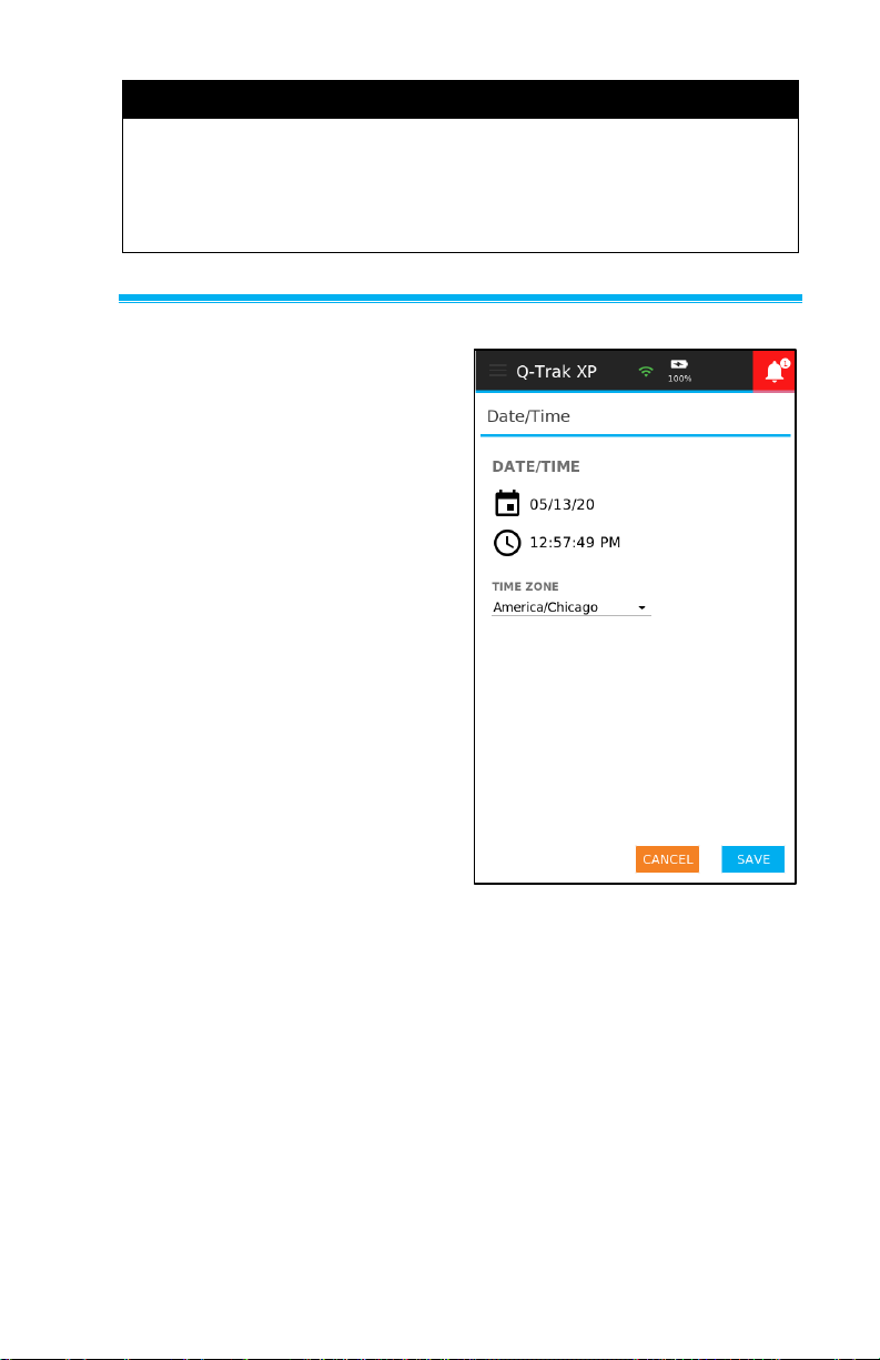
The Date/Time page is used to
set the current date, time, and
Time Zone. This information is
critical for logging data and
creating log schedules.
Page 40
26 Q-Trak™ XP IAQ Monitor Model 7585
Display/Power Management
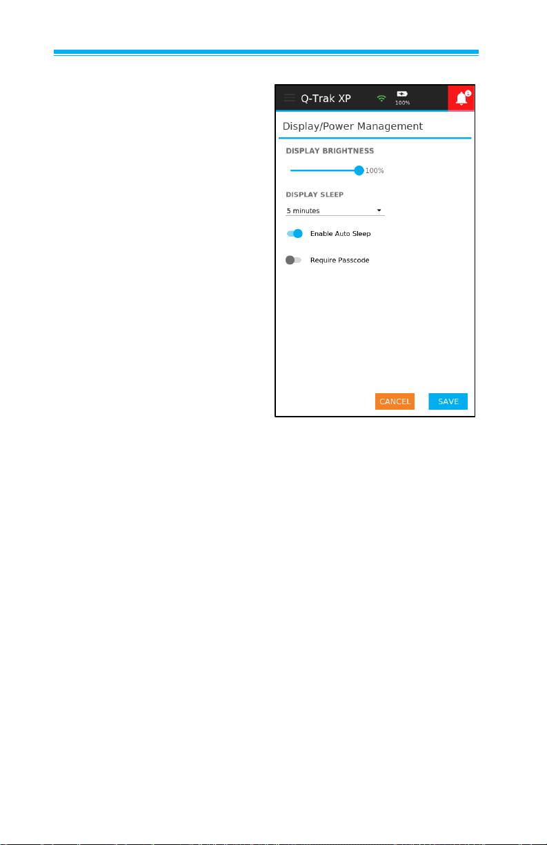
The Display/Power
Management page is used to
configure the following functions
• Display Brightness adjusts
the brightness of the display.
• Display Sleep sets the time
when the instrument enters
into sleep mode. Sleep
mode is a power-saving
state that darkens the
display. To exit sleep mode
touch the display. The
selectable sleep time options
are 1, 5, and 15 minutes. By
default, Display Sleep is
1 minute.
• Enable Auto Sleep enables
and disables sleep mode.
• Require Passcode enables
and disables the passcode
protection feature. Once the
instrument enters sleep
mode a passcode is required
to regain access (passcode
is 7585).
Page 41
Operation and Service Manual 27
Sensors
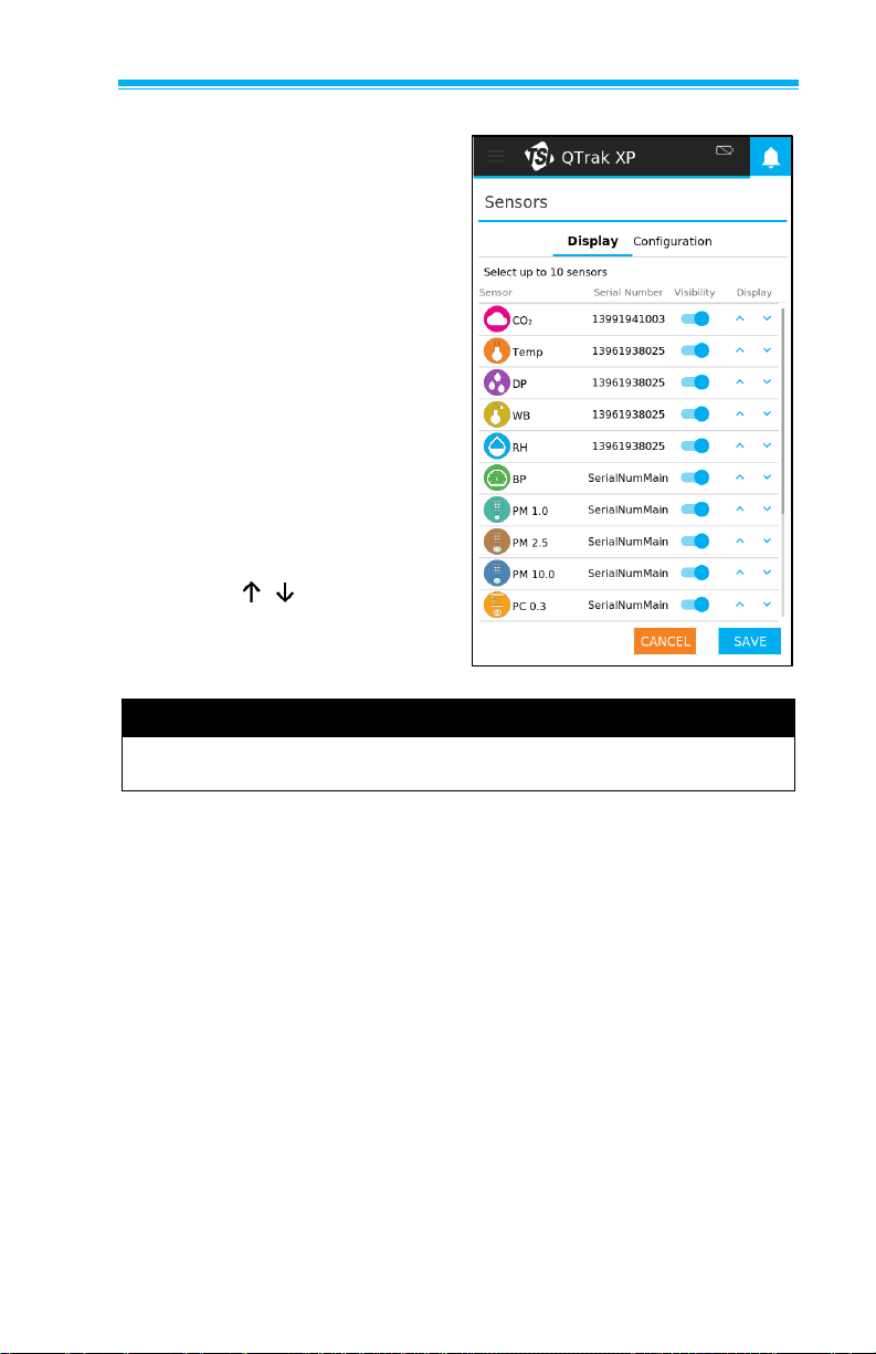
The Display section of the
Sensors page is used to
configure what sensors are
displayed on the Dashboard
page, and the order they are
displayed. To view sensors not
shown on the page, swipe up
and down. The list of sensors
includes the following
information:
• A sensor icon and name.
• A toggle button to enable
or disable the Visibility
of the sensor on the
Dashboard page.
• Up and down arrow
buttons to set the
order of the sensors on
the Dashboard page.
NOTE
The order of sensors on the Sensors page is the order shown on
the Dashboard page.
Page 42
28 Q-Trak™ XP IAQ Monitor Model 7585
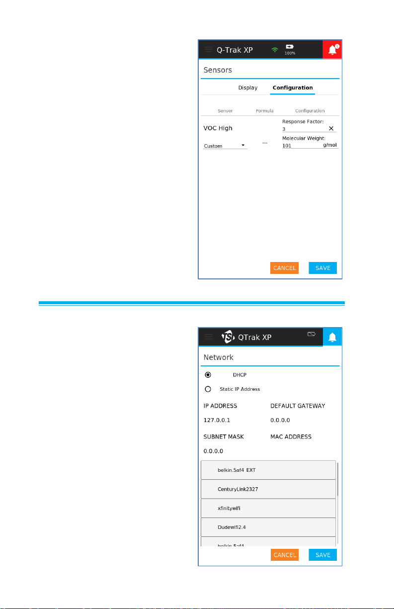
The VOC Configuration
section of the Sensors page is
used to select a specific
Volatile Organic Compound
(VOC). This is done by
selecting an already predefined VOC in the drop-down
list or by selecting Custom
and entering a Response
Factor and Molecular Weight.
• The Response Factor and
Molecular Weight are used
to calculate the actual
concentration of a
specific VOC.
Network Settings
The Network Settings page
is used to connect the
Q-Trak™ XP monitor to a
wireless network.
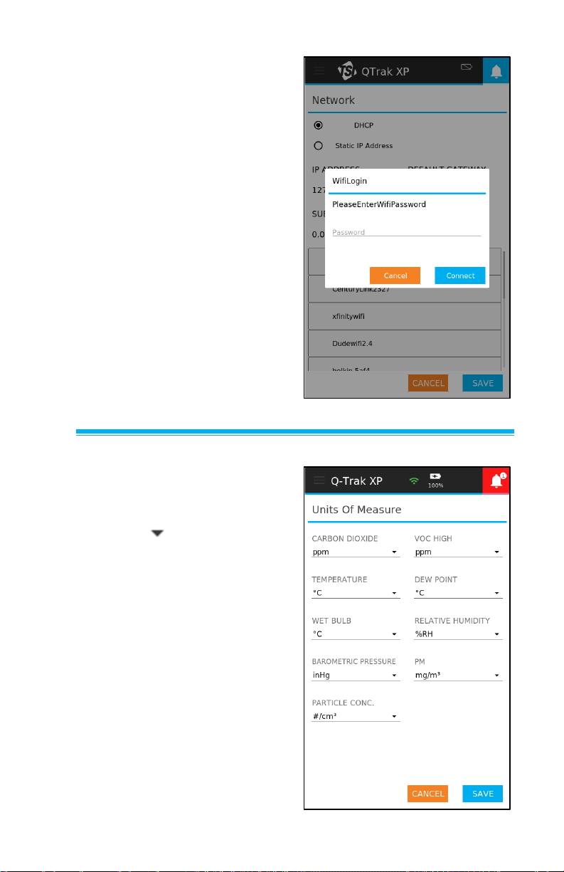
1. Select the Connect to
Network radio button.
2. Select a Wireless Network
down arrow to view the list of
available networks.
3. Select the desired network.
Page 43
Operation and Service Manual 29
4. Enter the network password
in the Network Password
field.
5. Select the CONNECT button
to connect the Q-Trak™ XP
monitor to the network.
6. Once connected the
Connection Status, IP
Address, Subnet Mask,
Connection Type, Default
Gateway, and MAC Address
will populate.
7. Select the Done button to
exit the Network Settings
page.
Units of Measure
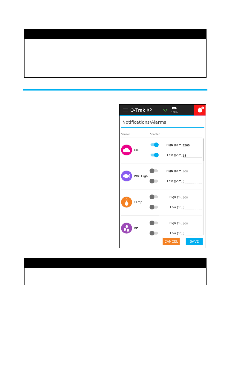
The Units of Measure page is
used to set the units of measure
for the installed sensors.
1. Select icon to view
the list of available units
of measure.
2. Select the desire unit
of measure.
3. Select SAVE button to
save changes.
Page 44
30 Q-Trak™ XP IAQ Monitor Model 7585
NOTE
The units of measure for all PM mass concentration
measurements (PM 1, PM 2.5, and PM 10) are set by the PM
drop-down list. Similarly, the units of measure of all particle
concertation measurements (PC 0.3, PC 0.5, PC 1.0, PC 2.5,
PC 5.0, PC 10.0) are set by the Particle Conc. Drop-down list.
Notifications/Alarms
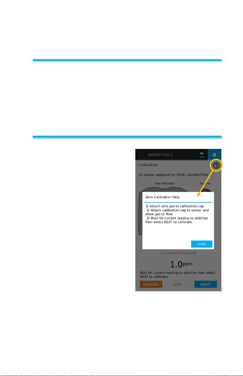
The Notifications/Alarms page
is used to enable and disable
notifications/alarms of the list of
sensors as well as setting their
trigger thresholds. The following
is included in this page.
• Toggle buttons to enable or
disable Notifications /
Alarms.
• Text fields to enter
Notifications / Alarms
thresholds.
• Lastly, to view sensors not
shown on the page, swipe
up and down.
NOTE
If two or more of the same sensor type is installed, only one will
trigger an alarm.
Page 45
31
CHAPTER 6
Calibration
Gas Sensors
TSI® recommends testing the accuracy of gas sensor measurements
each time the instrument is used. This is a common practice within
the gas measurement community which includes IAQ consultants
and industrial hygienists. Due to the nature of the sensors along with
other environmental factors such as altitude, temperature, and
relative humidity, the zero value and sensor sensitivity can shift over
time requiring you to perform a field calibration.
Gas Sensor Verification
Verifying the accuracy and
performance of a sensor can easily
be accomplished in the field by
comparing it to certified ZERO and
SPAN calibration gases (also
referred to as a “Bump Test”). To
do this, attach a calibration cap to
a bottle of the recommended
ZERO gas and place the cap onto
the gas sensor being checked. If
the probe reads a number outside
of the sensor accuracy after the
measurement has stabilized, the
sensor has drifted and needs to be
recalibrated. Perform the same
procedure with the recommended
SPAN gas to check the sensor
measurement against the certified
SPAN bottle concentration and
determine if a user calibration is
necessary. See Table 1 for recommended ZERO and SPAN gases.
Page 46

32 Q-Trak™ XP IAQ Monitor Model 7585
NOTE
For best results, power on the instrument for 10 minutes before
verifying gas sensor performance. This allows the instrument and
sensors to thermally stabilize and reduces the amount of
measurement drift during verification or calibration.
NOTE
Specific instructions for the calibration of each sensor are
available during calibration. To access the help for a sensor,
select and a pop-up appears with information to guide you
through specific sensor calibrations.
The following table shows the recommended calibration gases
and their respective concentrations (in ppm) for each gas sensor.
Calibration gases are available globally through local
distributors.
Table 1: Calibration Gases and Concentrations
Carbon Dioxide
(CO2)
Carbon Dioxide
(CO2)
5000
Nitrogen
TVOC – High
Isobutylene
(C4H8)
100
2000
Zero Air or
Nitrogen
100 ppm is the
first span
2000 ppm is
the second
span
TVOC - Low
Isobutylene
(C4H8)
20
Zero Air or
Nitrogen
Carbon Monoxide
(CO)
Carbon
Monoxide (CO)
400
Zero Air
Nitrogen Dioxide
(NO2)
Nitrogen Dioxide
(NO2)
20
Nitrogen
Nitric Oxide (NO)
Nitric Oxide
(NO)
20
Nitrogen
Chlorine (Cl2)
Nitrogen Dioxide
(NO2)
20
Zero Air
Nitrogen
Dioxide (NO2)
is used as a
surrogate
SPAN
calibration gas
Ozone (O3)
Nitrogen Dioxide
(NO2)
20
Zero Air
Nitrogen
Dioxide (NO2)
is used as a
surrogate
SPAN
calibration gas
Page 47
Operation and Service Manual 33
Hydrogen Sulfide
(H2S)
Hydrogen
Sulfide (H2S)
50
Zero Air
Ammonia (NH3)
Ammonia (NH3)
100
Zero Air
Formaldehyde
(CH2O)
Formaldehyde
(CH2O)
10
Zero Air
Gas Calibration Procedure
To perform a gas calibration,
required accessories and
material include a calibration
cap, ZERO calibration gas,
SPAN calibration gas, gas
regulator, and tubing. The
gas regulator used to control
the flow should be capable of
providing 0.3 L/min.
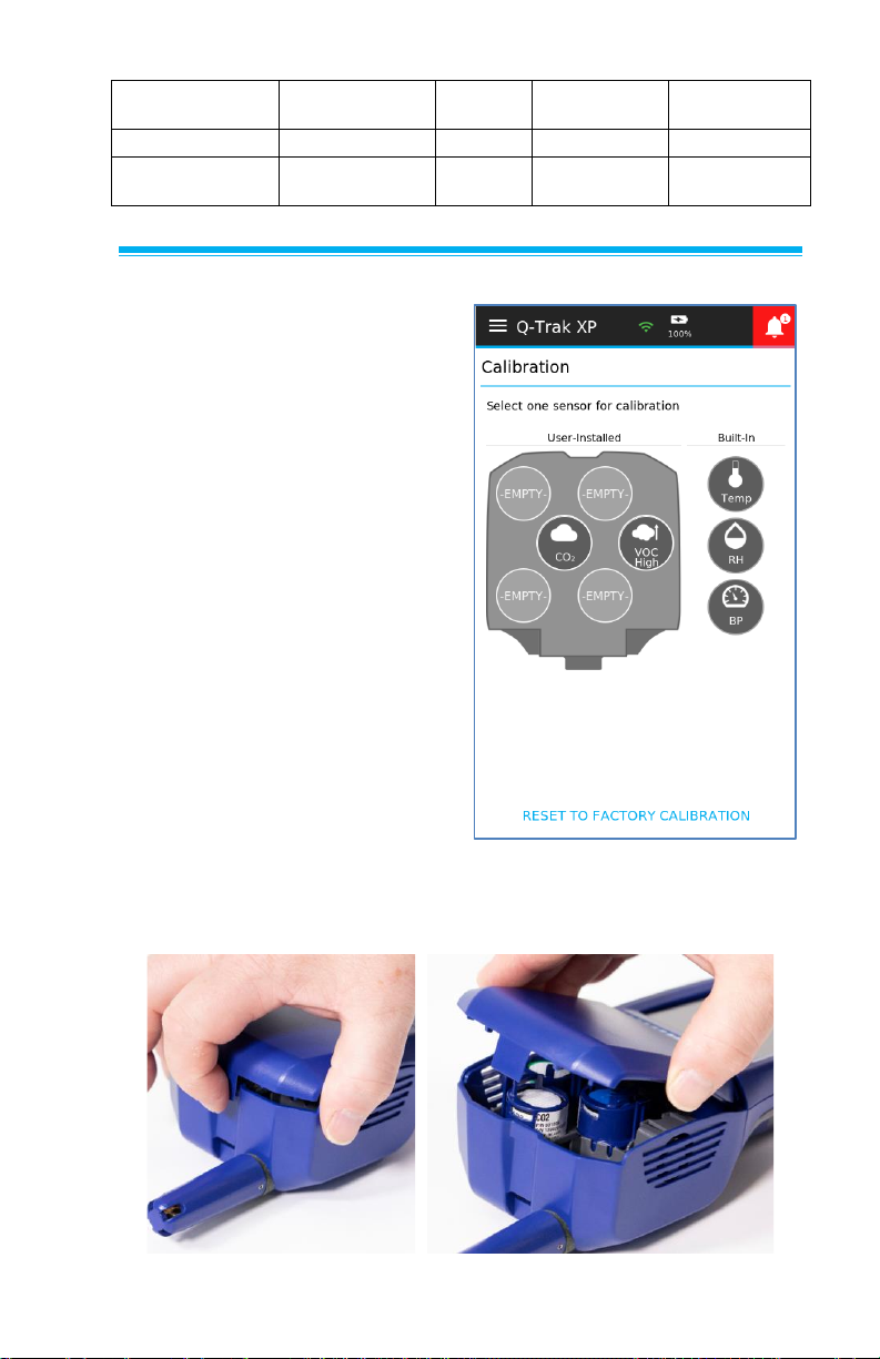
Select Calibration from the
Main Menu and the Calibration
page will appear showing the
available sensors for calibration.
All sensors appear grayed out
until you select the sensor they
would like to calibrate.
Step 1 – Select a Gas Sensor for Calibration
Remove the sensor module cover.
Page 48
34 Q-Trak™ XP IAQ Monitor Model 7585
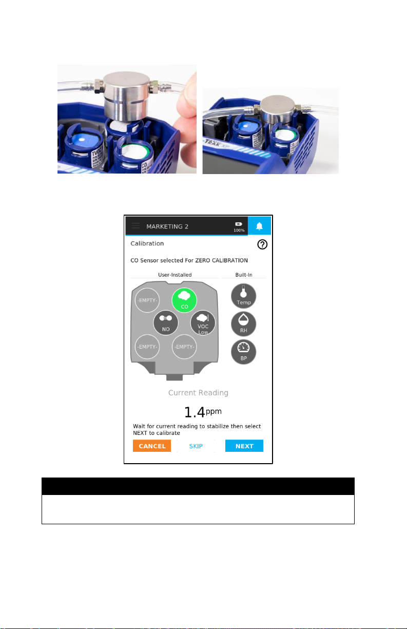
Step 2 – Place the calibration cap onto the gas sensor you want to calibrate
Step 3 - Select the sensor to be calibrated on the instrument display
NOTE
You have the ability to “SKIP” either the ZERO and/or SPAN gas
calibration steps during the calibration process.
Page 49
Operation and Service Manual 35
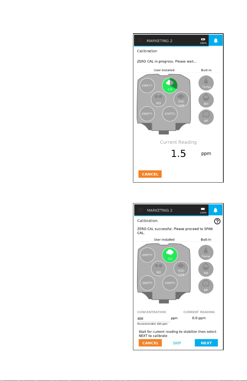
Step 4 - Perform ZERO Capture
1. Connect the ZERO gas
regulator to the calibration
cap and start the flow of
ZERO gas. Wait for the
measurement to stabilize.
2. Once the ZERO
concentration looks
stable, select Next to
perform a ZERO
concentration capture.
An illuminated dial will
appear on the sensor
icon showing the time
remaining.
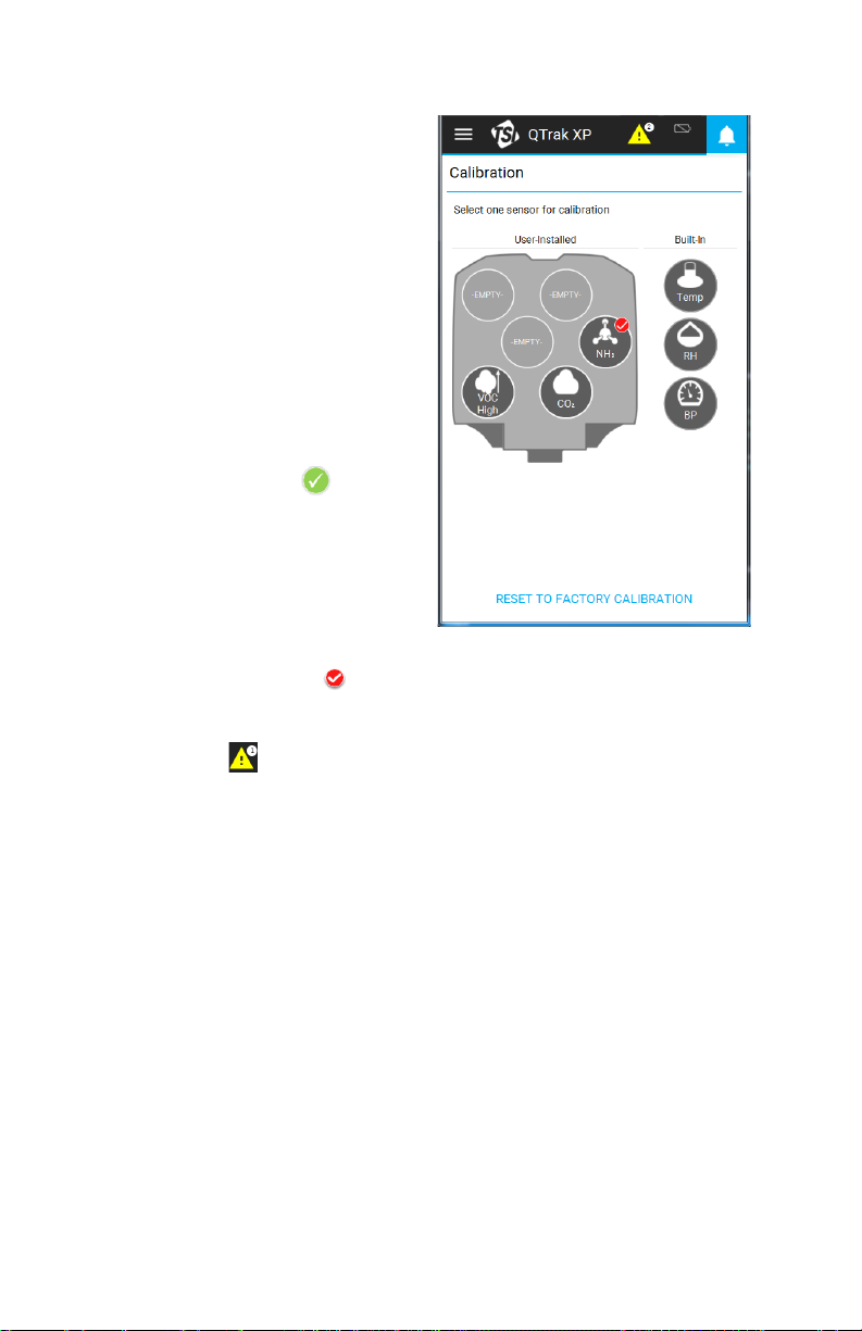
Step 5 – Perform SPAN Capture
1. Enter the SPAN gas bottle
concentration into the
reference concentration field
using the numeric keypad.
2. Connect the SPAN gas
regulator to the calibration
cap and start the flow of
SPAN gas. Wait for the
measurement to stabilize.
3. Once the span concentration
looks stable, select Next to
perform span concentration
capture. An illuminated dial
will appear on the sensor
icon showing the time
remaining.
Page 50
36 Q-Trak™ XP IAQ Monitor Model 7585
Step 6 – Save or Discard Calibration
A CALIBRATION ADJUSTMENT
% is displayed after the SPAN
capture that informs you how
much the sensor’s calibration
slope has changed from the
factory calibration slope.
1. Select Save to accept
the calibration.
2. Select Cancel to quit the
calibration procedure and
discard calibration.
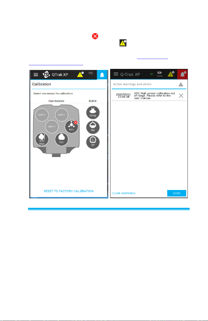
3. A successful calibration will
be indicated by a near
the sensor icon.
4. If the calibration reading
completes but the Reference
Calibration gas concentration
is out-of-range than what is
recommened by the device,
the page displays a near
the sensor icon and a
warning notice is sent to the
Notice list in the heading
bar of the instrument.
An Out-of-Range error during the calibration of a sensor means
the sensor’s offset or calibration slope adjustment has drifted
outside of the TSI® recommended specification for continued
use. Sensor should be replaced or sent to TSI® for re-calibration.
Page 51
Operation and Service Manual 37
Gas Calibration Unsuccessful
If a sensor has drifted beyond the TSI® recommended calibration
adjustment specification, a is displayed by the sensor icon and a
warning notice is sent to the Notice list in the heading bar of the
instrument. TSI® recommends replacing the sensor. However, the
sensor is calibrated and can still be used. See Out of Range in
Appendix B, Definitions for more information.
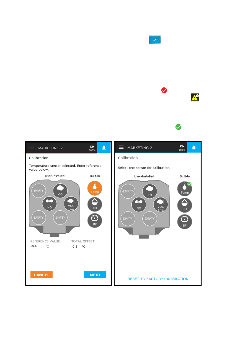
Built-in Sensor Calibration: Temperature, Relative Humidity, and Barometric Pressure Sensors
To calibrate the Temperature, Relative Humidity, and Barometric
Pressure sensors:
Select either the Temperature, Relative Humidity, or Barometric
Pressure sensor icon on the Calibration page. A Reference Value
for the sensor will appear.
Page 52
38 Q-Trak™ XP IAQ Monitor Model 7585
The Reference Value is the current reading of the sensor. This
reading can be changed by selecting on the Reference Value text
field and entering the desired value and select < >. Select Next
then Save and the new value is displayed as the Reference Value.
The Total Offset is the adjustment from the original factory
calibration for that sensor. This lets you track the overall drift of
the sensor.
If the drift exceeds the factory allowable tolerance, a is displayed
by the sensor icon and a warning notice is sent to the Notice list
in the heading bar of the instrument that instructs you to return the
unit to TSI® for service.
Calibration that is within the factory allowable tolerance, a is
displayed by the sensor icon.
Page 53

Operation and Service Manual 39
Reset Sensors to Default Calibration
To reset the sensors to
their factory defaults,
1. Return to the
Calibration page
and select Reset to
Factory Calibration
at the bottom of the
page.
2. Select the sensor(s) to
be reset.
3. When the selected
sensor(s) are
highlighted, select
RESET.
4. Select Yes or No.
Selecting Yes resets
the sensor(s) to the
factory calibration.
Page 54

40 Q-Trak™ XP IAQ Monitor Model 7585
(This page intentionally left blank)
Page 55

41
CHAPTER 7
Logging Data
From the Main Menu select
Dashboard then select
> Logging at the top of the
page. This leads to the
Dashboard page with the Start
button as shown below.
From this page either select
Start to begin logging data
based on the selected Logging
Profile or define a Logging
Profile by selecting .
NOTES
When selecting START
before creating a Logging
Profile the Q-Trak™ will log
data based on a default
Logging Profile and log a
single reading from all
available sensors using a
sample interval of 1 second.
Page 56
42 Q-Trak™ XP IAQ Monitor Model 7585
Logging Data
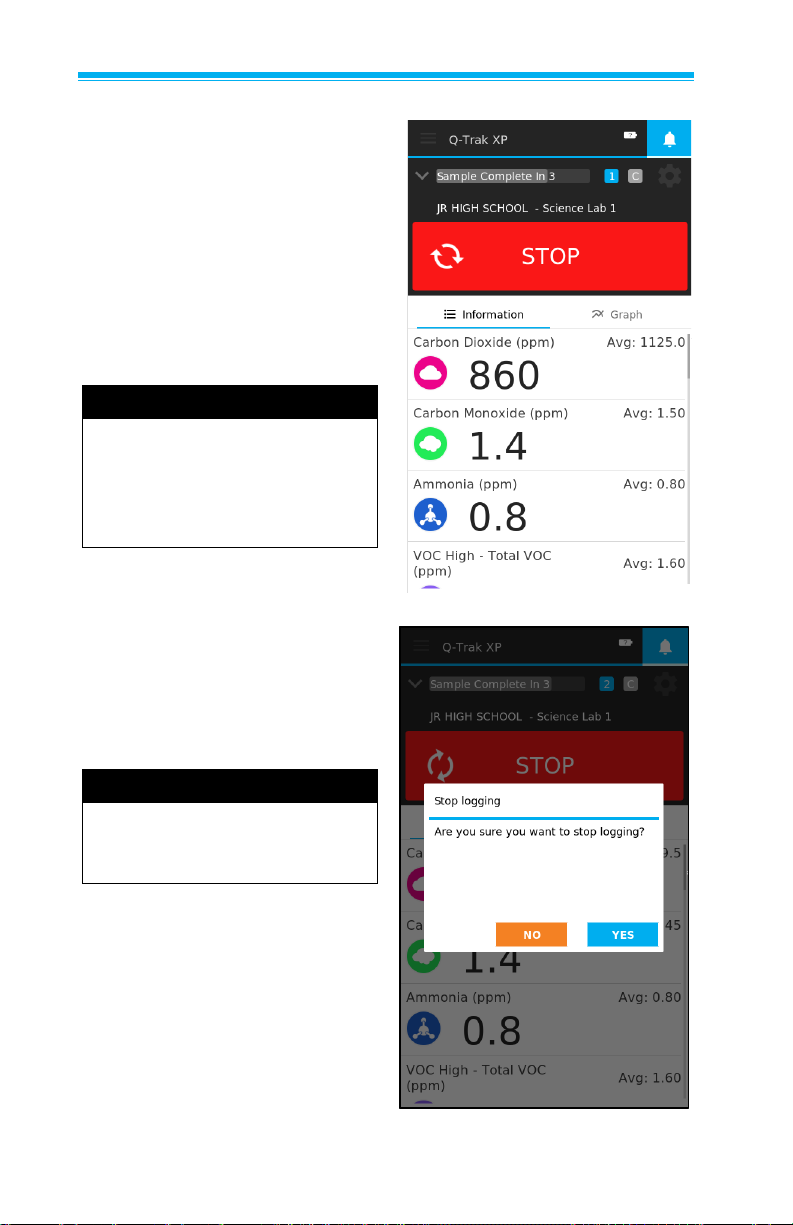
To begin logging data,
select START.
When logging is initiated, the
Dashboard page displays
second by second measurement
readings next to the sensor icons
while the Avg value is the
average of all readings in the
log file.
NOTE
On-board memory is capable
of storing data from all
available sensors for 30 days
when sampling data once
a minute.
You can log data with Manual
Save, Continuous Save, or
Scheduled Save (see figure). To
stop logging at any time, select
STOP then select Yes.
NOTE
The Q-Trak™ always logs
data from all available
sensors.
Page 57
Operation and Service Manual 43
Logging Profiles
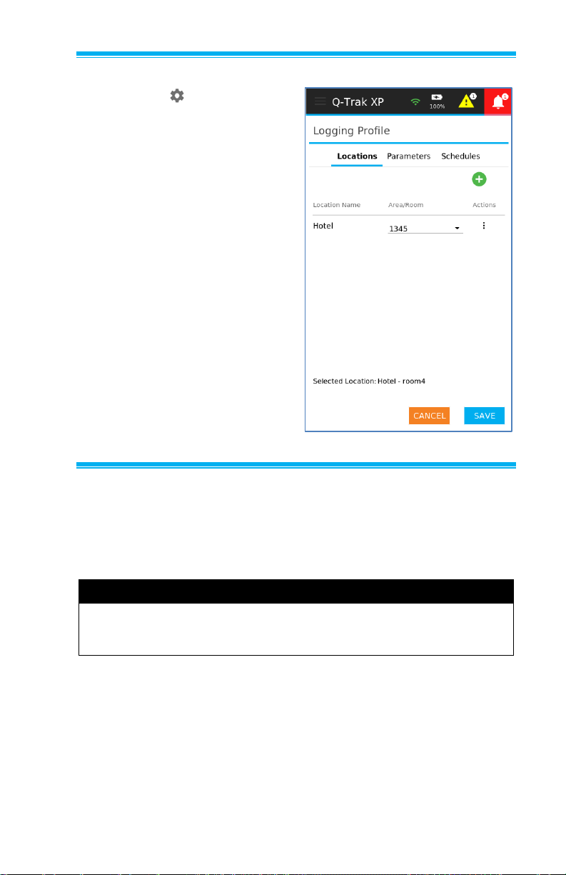
Selecting the from the
Dashboard page leads to the
Logging Profile page where
you define and select a logging
profile. A logging profile is
composed of a Locations and
Settings such as Logging
Mode. If Scheduled Save
Logging Mode (see figure) is
selected then a schedule must
be defined.
The following subsections
describe how to add/change
Locations, Settings, and
Schedules.
Locations
A location is composed of a Location Name, typically a building,
and an Area/Room in the building. The highlighted location is the
currently selected location. To change the current location, select
another location in the list.
NOTE
The list of locations can exceed the number of locations that
are visible on the display. To view additional locations swipe up
or down.
On the Logging Profile page select Locations.
Page 58
44 Q-Trak™ XP IAQ Monitor Model 7585
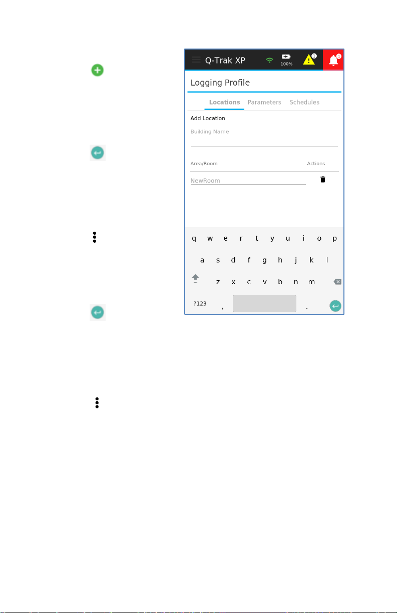
To create a new location:
1. Select to create a
new location.
2. Enter a Building
Name.
3. Enter Area/Room.
4. Select and select
Done to add a location.
5. Select Save to save
the location.
To edit an existing location:
1. Select and select
Edit for the location.
2. Edit the Building Name
and/or Area/Room for
the Location.
3. Select and select
Done to complete
editing.
4. Select Save to save the change.
To delete a location:
1. Select and select Delete for the Location.
2. Select SAVE to delete the location.
Page 59
Operation and Service Manual 45
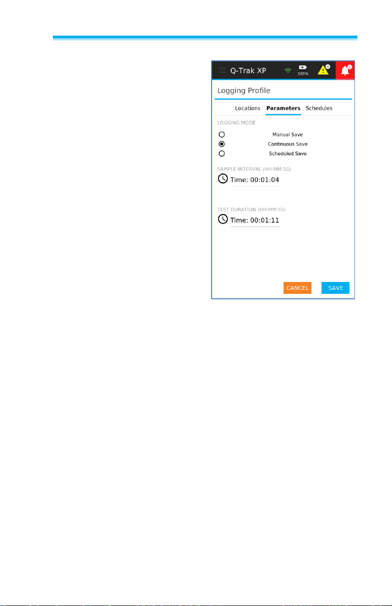
Settings
Settings include Logging
Mode, Sample Interval, Test
Duration, and other items such
as Select Logging Schedule.
Logging Mode
There are three logging modes:
• Manual Save
• Continuous Save
• Scheduled Save
Manual Save logging mode
averages measurements
collected during the sample
interval and records the
average value in the log file.
Once the sample is complete
the application prompts you to
either select START or DONE.
Select START to take another
sample or DONE to end the
logging session.
Selecting the View Before Save toggle button to ON, Manual Save
prompts you to either SAVE or DISCARD once the sample is
complete. Swipe up or down to view the collected data then select
SAVE or DISCARD to save or discard the data. After selecting
SAVE or DISCARD the page will display START or DONE. Select
START to take another sample or DONE to end the logging session.
Continuous Save logging mode averages measurements collected
during the sample interval and records the average value in the log
file. Unlike Manual Save mode, Continuous Save mode continues
logging data until the Time Duration time has elapsed. In this mode,
the sample data is automatically saved to memory at the end of the
sampling interval and you are not given the option to view the data
before saving.
Page 60
46 Q-Trak™ XP IAQ Monitor Model 7585
Schedule Save collects data according to a user-defined schedule
with a specific start and end date and time. Moreover, this logging
mode averages measurements collected during the sample interval
and records the average value in the log file like the previous logging
modes. Lastly, the data is automatically saved without user
intervention.
Sample Interval
Sample interval is used in all three logging modes to set the time
between samples. It can be as short as one second or as long as
99 hours, 59 minutes, and 59 seconds.
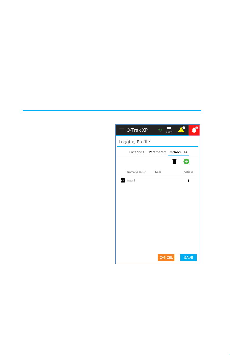
Schedules
To set up schedules for logging,
Select Schedules from the
Logging Profile page.
Page 61
Operation and Service Manual 47
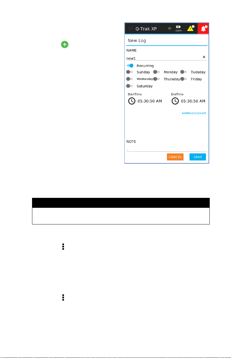
To create a new logging
schedule:
1. Select to create a
logging schedule.
2. Enter a schedule name.
3. If this is a recurring logging
profile, select Recurring and
select the days of the week
to log data.
4. Enter start times and end
times as desired.
5. If an additional time segment
is desired, select Add New
Segment and enter a start
time and end time.
6. Repeat step 5 to add more
time segments.
7. Add Notes to the schedule if desired.
8. Select DONE to finish editing and select SAVE to save changes.
NOTE
The list of time segments can exceed what is shown on the
display. To view additional time segments swipe up and down.
To edit an existing logging schedule:
1. Select and then select Edit.
2. Modify the schedule as desired.
3. Select DONE to finish editing and select SAVE to save changes.
To delete an existing logging schedule:
1. Select and select Delete.
2. Select Yes.
Page 62

48 Q-Trak™ XP IAQ Monitor Model 7585
(This page intentionally left blank)
Page 63
49
CHAPTER 8
Manage Data
From the Main Menu select Manage Data.
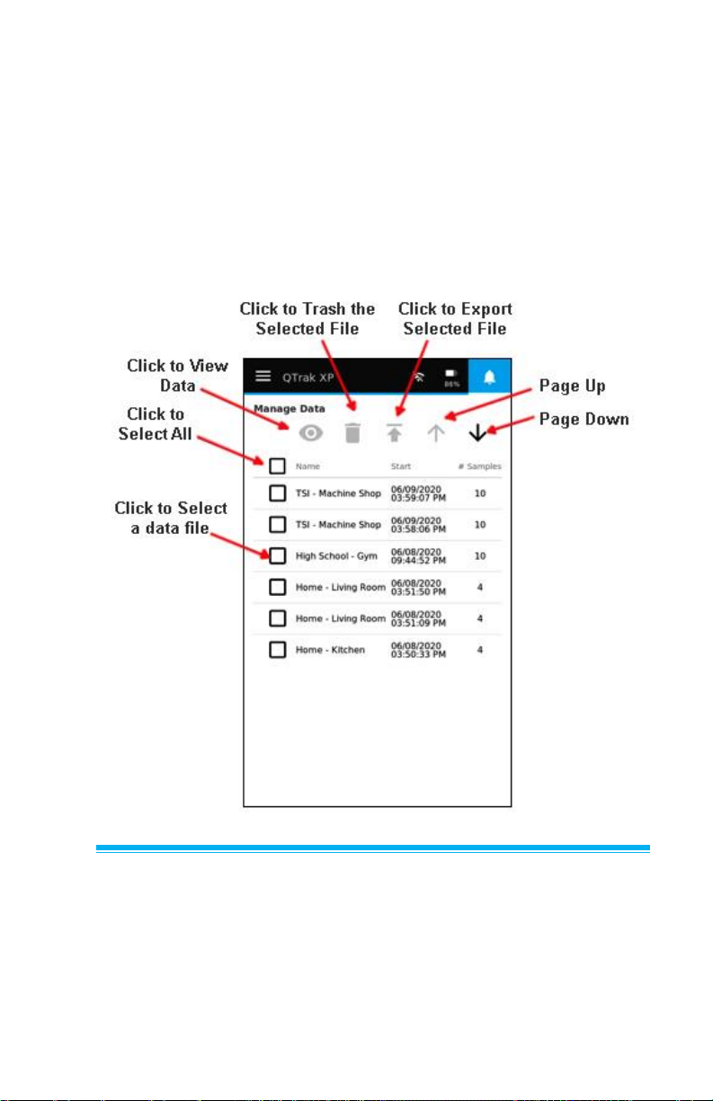
The Manage Data page contains all logged files on the device. You
can select a log file for viewing, deleting, exporting, and editing. As
well as scrolling through a list of log files.
Selecting Log Files
Select a log file by selecting a checkbox. Multiple log files can be
selected by selecting additional checkboxes while all log files can be
selected by selecting the checkbox at the top of the page.
Page 64
50 Q-Trak™ XP IAQ Monitor Model 7585
View Log Files
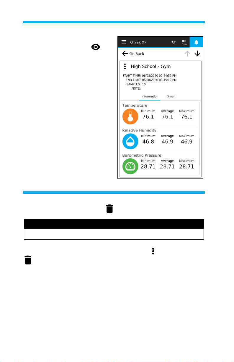
To view a log file select the
checkbox then select the
icon. To view all the data in a log
file swipe up and down and to
view data over time select
Graph. If more than one log file
is selected for viewing, select the
up and down arrows to view the
other log files.
Delete Log Files
Select a log file then select the icon to delete it. Next select YES.
NOTE
Deleted log files cannot be recovered.
Alternatively, when viewing a log data file select then select the
icon.
Page 65

Operation and Service Manual 51
Export Log Files
Logged data files can be exported to a USB flash drive or to a PC
via TrakPro™ Ultra Software.
Exporting to USB Drive
Attach a USB flash drive (thumb drive) to the Q-Trak™ monitor via
the USB port next to the power jack. Select a log file from the menu
and then select icon.
Alternatively, when viewing a logged data file, select the menu
and then select to export the file to the flash drive.
Files will be transferred to the USB drive in .CSV format for use with
spreadsheets on a computer.
Exporting Files to a PC
Connect the instrument to a computer via Wi-Fi® or the USB-C Cable
supplied with the instrument.
Open TrakPro™ Ultra Software on the PC (see TrakPro™ Ultra
Software user manual) and select a log file from the menu and then
select icon.
Alternatively, when viewing a logged data file, select the menu
and then select to export the file to the PC in a .db File format for
use with TrakPro™ Ultra Software. Files can then be exported as
.csv or other file formats for use with other software.
NOTE
If exporting data to a USB flash drive, and there is not enough
space on the drive to house the file, or if some other error occurs
during the export, the following warning message will appear:
“Data Export Failed – Please Check USB Drive.” This warning
will persist unit it is dismissed.
Page 66
52 Q-Trak™ XP IAQ Monitor Model 7585
Edit Log File Names
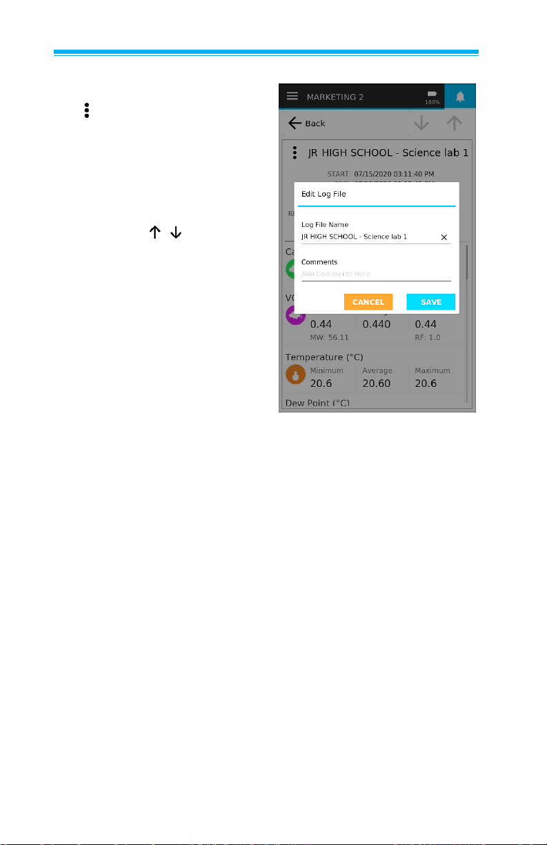
When viewing a log file, select
the icon and then select Edit.
Enter a new Log File Name and
add a comment if desired.
Scrolling Through Data List
When the list of log files exceeds
what can be viewed on the
display, select icons to
scroll through the list of log files.
Page 67
53
CHAPTER 9
Workflows
The following workflows are available:
• % Outside Air (%OA) calculation procedure.
Percent Outside Air (%OA) Calculation Procedure
For those unfamiliar with
Percent Outside Air (%OA)
Calculation and its use, please
read TSI® Application Note
TI-138, which is found on the
TSI® website at
https://www.tsi.com. It is
important to understand what
% Outside Air is, why it is
important, and how to use this
instrument to calculate %OA.
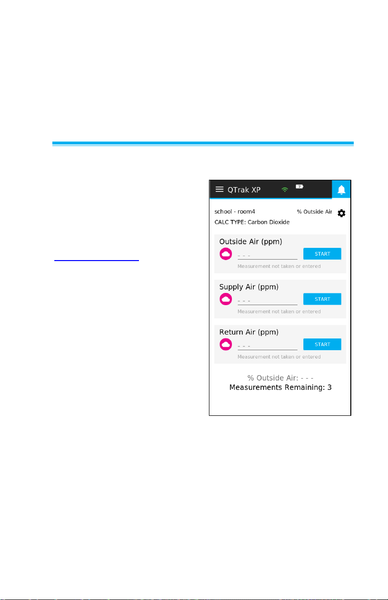
After selecting Workflows
from the Main Menu, select
%Outside Air to view the %
Outside Air room.
Page 68
54 Q-Trak™ XP IAQ Monitor Model 7585
Three measurements are
necessary for % Outside Air
calculations - Outside Air,
Supply Air, and Return Air.
The measurements may be
taken in any order. The
calculation is performed once
the final measurement is taken.
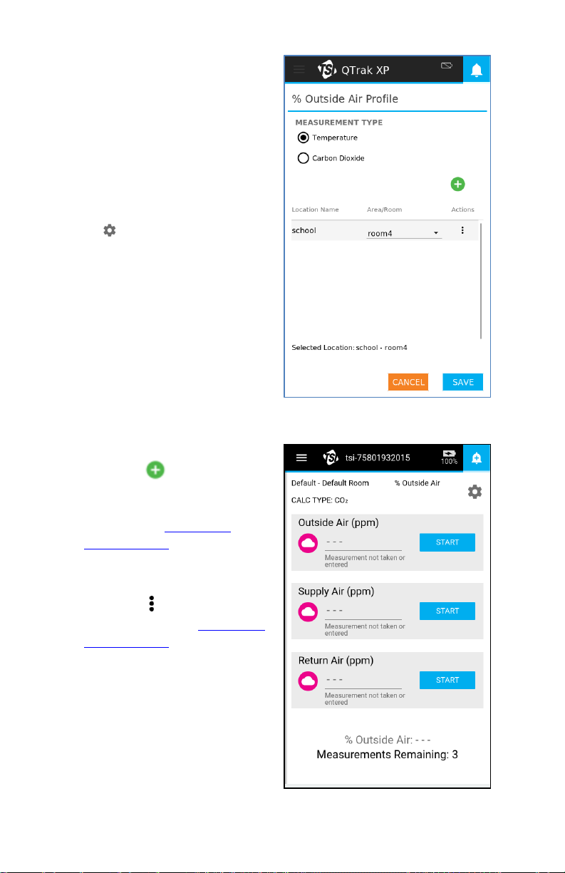
Before taking a measurement
select icon to create a
% Outside Air Profile.
From the % Outside Air Profile
page, you can:
• Select a CO2 or
Temperature as the
Measurement Type. If
necessary, review the
application note TI-138 to
determine which option
to use.
• Add a new location by
selecting icon and enter
a Building Name and
Area/Room. Similar to what
was done in Chapter 7
Logging Data.
• Edit or Delete existing
logging profile locations by
selecting icon. Similar to
what was done in Chapter 7
Logging Data.
• Select Save or Cancel as
desired to return to the
%Outside Air page.
Page 69
Operation and Service Manual 55
As mentioned above, three measurements are necessary for %
Outside Air calculations - Outside Air, Supply Air, and Return Air.
The measurements may be taken in any order. The calculation is
performed once the final measurement is taken.
IMPORTANT
The Q-Trak™ XP instrument is intended for indoor use only. Care
should be taken when taking % of Outdoor Air measurements so
that the instrument is not exposed to rain, sleet, hail, snow or other
inclement weather conditions as exposure to these elements will
void the factory warranty.
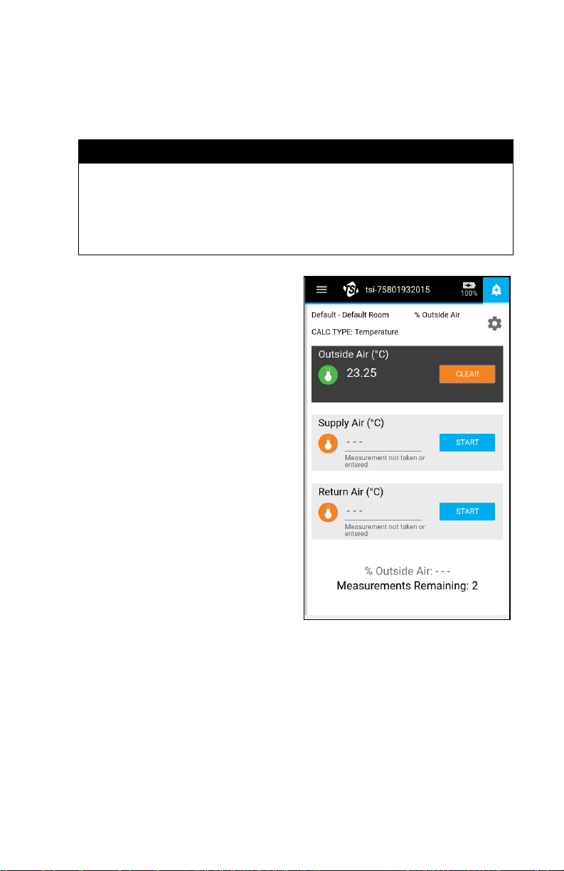
1. Position the Q-Trak™
monitor outside to perform
the Outside Air
measurement, select
START, and wait until the
measurement is complete.
2. The % Outside Air page
shows the number of
outstanding readings needed
before a calculation can
be made.
3. Position the Q-Trak™
monitor in the supply vent to
perform the Supply Air
measurement, select
START, and wait until the
measurement is complete.
4. Lastly, position the Q-Trak™
monitor by the return vent to
perform the Return Air
measurement, select
START, and wait until the
measurement is complete.
5. If a measurement (Outside Air, Supply Air, or Return Air) needs
repeating select CLEAR then select START.
6. Once the measurements are complete, the % Outside Air is
calculated and shown on the bottom of the page.
Page 70
56 Q-Trak™ XP IAQ Monitor Model 7585
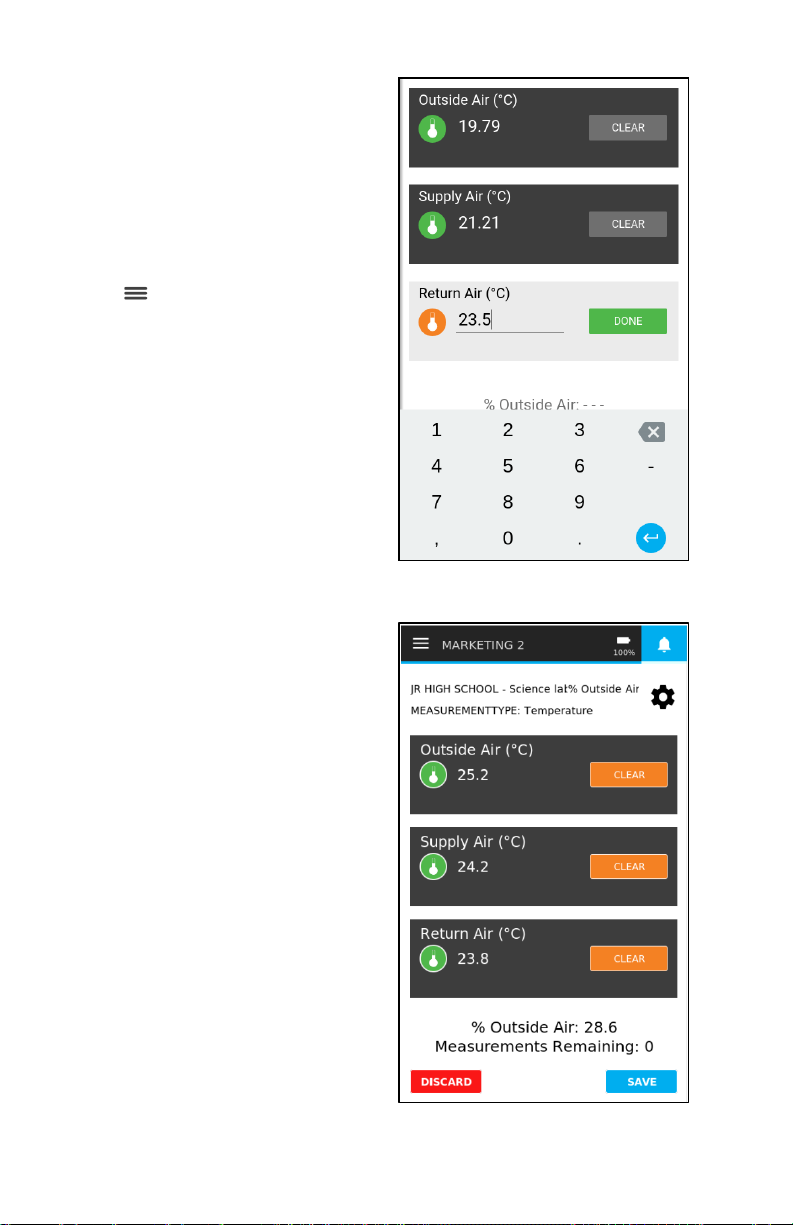
7. Select DISCARD to discard
all measurements or select
SAVE to save the %
Outdoor Air Calculation.
8. After saving the % Outdoor
Air Calculation you can
perform another % Outdoor
Air calculation or select the
icon to exit the %
Outside Air page.
Instead of making
measurements, you have the
option of entering values for
Outside Air, Supply Air, or
Return Air by selecting --- and
typing the appropriate value.
Select DONE when finished. The
calculation is then made using
entered value(s).
Lastly, if the % Outside Air
calculation cannot be made
using the measurements /
entered values, an error
message is shown along with a
DISCARD button.
Selecting DISCARD clears all
measurements/entered values
and you may start over.
Alternatively, you can select
Clear to clear a single
measurement/entered value
and repeat taking the
measurement/enter a new
value.entered value(s).
Page 71

57
CHAPTER 10
TrakPro™ Ultra Software
Post-test analysis and report generation is performed using the
TrakPro™ Ultra software application.
To install TrakPro™ Ultra Software:
1. Using a web browser, navigate to https://tsi.com/support/tsi-
software-and-firmware/ and enter the search term Q-Trak XP.
2. Download the TrakPro™ Ultra software application by following
the on-screen instructions.
NOTE
The manual for TrakPro™ Ultra Software is embedded in
the application.
Page 72

58 Q-Trak™ XP IAQ Monitor Model 7585
(This page intentionally left blank)
Page 73
59
CHAPTER 11
Update Instrument Software
The Device Information page allows you to update the
Q-Trak™ XP software without having to return the instrument
to TSI® Incorporated.
To update the firmware:
1. Access the TSI® website site at www.tsi.com/7585 using
a computer.
2. Select the latest software version and download it to a USB
thumb drive.
3. Insert the USB drive into the USB port on the end of the
Q-Trak™ XP instrument
and turn the instrument on.
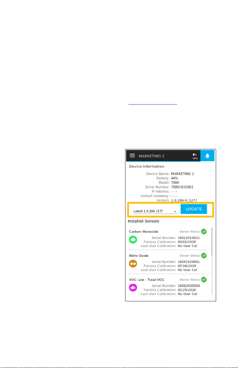
4. Select Device Information
from the Main Menu.
5. Select the drop-down arrow
to view all available
software versions.
6. Select the latest version of
the software.
7. Select the UPDATE button.
8. The instrument will shut
down while updating. Allow
the update to complete
before attempting to
perform any operations.
9. The instrument will reboot
after updating the software
and is ready to use with the
updated software.
Page 74

60 Q-Trak™ XP IAQ Monitor Model 7585
(This page intentionally left blank)
Page 75
61
CHAPTER 12
Maintenance
Replacing Sensors
Replacement sensors are sold separately and available through
TSI® Incorporated. Refer to Chapter 2 for replacement parts.
Recalibration
See Chapter 6. Calibration for information on how to calibrate
sensors.
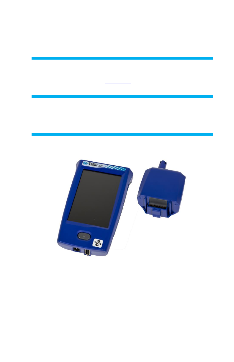
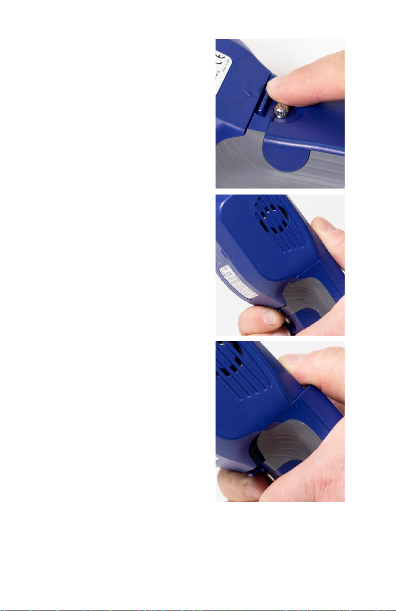
Removing the Sensor Module from the Handle of the Q-Trak™ XP Monitor.
Page 76
62 Q-Trak™ XP IAQ Monitor Model 7585
To remove the sensor module from
the handle of the instrument,
proceed as follows:
1. Turn the instrument OFF.
2. Turn the instrument over and
press upward on the release
tab just above the back-cover
screw as shown in the picture.
3. Turn the instrument over
and hold it as shown while
continuing to press on the
release tab as previously
described.
4. Press downward with both
thumbs while holding the
release tab above the backcover. This requires some
steady force.
Page 77
Operation and Service Manual 63
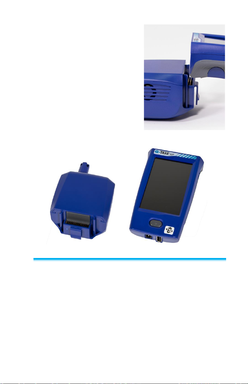
5. Continue to press down until
the sensor module is free from
the handle.
6. Separate the sensor module
from the handle.
7. Separation complete.
Storage
When storing the instrument for extended periods, remove the
battery after fully charging before storage. Also, remove the sensors
and store them in their original “snap cap” containers. When
re-installing the battery, refer to the initial battery instillation process
for calibrating the battery status gauge.
Page 78

64 Q-Trak™ XP IAQ Monitor Model 7585
(This page intentionally left blank)
Page 79

65
CHAPTER 13
Troubleshooting
Table 2 lists the symptoms, possible causes, and recommended
solutions for common problems encountered with the Model 7585. If
your symptom is not listed, or if none of the solutions solves your
problem, please contact TSI® Incorporated.
Table 2: Troubleshooting the Model 7585
Symptom
Possible Causes
Corrective Action
Blank display
Depleted battery
Plug in AC adapter to charge
battery
Damaged display unit
Return to TSI® for service
Battery will not
charge
Damaged battery
Replace battery
Battery disconnected
Connect battery in battery
compartment
Touch screen
display not
responding
Instrument software
issue
Press the power button for 10
to 12 seconds to turn off the
instrument. Then press the
power button to turn the
instrument back on.
Damaged display unit
Return to TSI® for service.
Gas sensor is
installed, but not
visible in the
Sensors page
Sensor was installed
while the instrument
was powered.
Power cycle the instrument.
Damaged sensor
Install sensor in another
location in the sensor module.
If the sensor continues not be
detected. Contact TSI® to
service or replace the sensor.
If the warranty period has
expired it may be necessary to
purchase a new sensor.
Page 80

66 Q-Trak™ XP IAQ Monitor Model 7585
Symptom
Possible Causes
Corrective Action
Gas sensor is
installed, but not
visible in the
Sensors page
(cont.)
Damaged gas sensor
module
Install sensor in another
location in the sensor module.
If the sensor is detected.
Contact TSI® to service or
replace the sensor module. If
the warranty period has
expired it may be necessary to
purchase a new sensor
module.
Gas sensor fails
calibration
Wrong gas is being
used to calibrate
sensor.
Verify the correct gas is being
used.
Calibration cap is
attached to wrong
sensor.
Verify the calibration cap is
attached to the correct sensor.
Fan no longer
rotating
Fan is jammed by
dust, dirt, or other
contaminant
Clean the fan while instrument
is powered off with
compressed air
Damaged fan or
module
Return to TSI® for service
Sensors not
visible on the
Dashboard
Sensor not turned on
in the Sensors page.
From the Main Menu select
Settings then select Sensors.
Once in the Sensors page
select the appropriate toggle
button to make the sensor
visible on the Dashboard.
Density
correction
warning
Faulty Barometric
Pressure or
Temperature sensor(s)
Return to TSI® for Service
From the Main Menu select
Settings then select General
Settings. Once in the General
Setting page select Density
Correction toggle button to
turn off Density Correction.
Page 81

Operation and Service Manual 67
Symptom
Possible Causes
Corrective Action
While powering
the Q-Trak™ XP
monitor the
instrument
unexpectedly
powers off.
Battery power is fully
discharged.
Charge battery with supplied
power supply.
Replace battery.
Battery temperature
sensor measures a
temperature greater
than 60°C.
Place the Q-Trak™ monitor in
a cooler environment and wait
approximately 15 minutes.
Then power instrument.
Replace battery.
Battery temperature
sensor measures a
temperature less
than -20°C.
Place the Q-Trak™ monitor in
a warmer environment and
wait approximately 15 minutes.
Then power instrument.
Replace battery.
Unable to
connect
TrakPro™ Ultra
software to
Q--Trak™ XP
monitor via
USB-C cable.
USB-C cable is
damaged.
Use another USB-C cable.
Q-Trak™ XP monitor
is connected to a
Wi-Fi® network.
Disconnect Q-Trak™ XP
monitor from Wi-Fi® network
then connect TrakPro™ Ultra
to Q-Trak™ XP monitor via
USB-C cable.
Alternatively, use Wi-Fi®
network to connect TrakPro™
Ultra to the Q-Trak™ XP
monitor.
Unable to
connect
TrakPro™ Ultra
software to
Q-Trak™ XP
monitor via
Wi-Fi®.
Router assigned the
same IP address to
the Q-Trak™ XP
monitor and another
device.
Reboot the Q-Trak™ XP
monitor.
Page 82

68 Q-Trak™ XP IAQ Monitor Model 7585
Unexplained
rapid changes
in CO
2
measurement.
Radio frequency
interference.
Identify whether the following
electronic devices capable of
transmitting radio waves are
nearby: microwave ovens,
Wi-Fi® routers, cellular phones,
or personal communication
devices, i.e., walkie-talkie,
two-way radios.
If one of these devices is
present, turn them off or place
them in a mode that does not
transmit. Alternatively,
increase the distance between
the Q-Trak™ monitor and
transmitting device unitl the
problem is no longer present.
NOTE: Other electronic
devices capable of transmitting
radio waves may also
adversely impact the CO2
measurement.
Error Messages
Message
Definition
<SensorType> is in error.
ERRCODE: Corrupt
Reading
Cannot calculate measurement value
due to erroneous User Calibration or
missed measurement.
<SensorType> is in error.
ERRCODE: No Reading
Cannot execute sensor due to
sensor being removed or faulty
sensor electronics.
Density correction warning
Cannot compensate for density
changes due to faulty Barometric
Pressure or Temperature sensor(s).
PID electronics error.
Service or replace
VOC sensor
VOC sensor's electronics (Bulb
and/or Stack) is faulty.
Page 83

Operation and Service Manual 69
Message
Definition
Sensor error. Service or
replace <SensorType>
sensor
Cannot initialize sensor due to
corrupt sensor memory or faulty
electronics.
Battery is faulty. Please
replace battery.
Battery has been depleted to
unsafe level.
The battery is too cold to
run. Saving data and
shutting down…
Battery temperature has
dropped below -20°C and is
unsafe to operate.
The battery is too hot to run.
Saving data and shutting
down…
Battery temperature has exceeded
60°C and is unsafe to operate.
Battery too cold to charge
Battery temperature is between
-20°C and 0°C and cannot
safely charge.
Battery critically low. Plug
in charging cable. Device
will shut down in
<30 Second Timer>
Apply AC power and allow battery
to charge.
Battery low. Plug the power
cord into the instrument or
auto shutdown will
occur soon.
Battery has less than 15 minutes of
runtime remaining.
Fan error. Service sensor
module.
Sensor module fan is blocked
or faulty.
Temperature sensor error.
Service sensor module.
Temperature sensor is faulty.
Barometric pressure sensor
error. Service sensor
module.
Barometric Pressure sensor is faulty.
Measurement Value =
88888888
Cannot calculate measurement
value possibly due to erroneous
User Calibration, faulty sensor, or
sensor removed.
Page 84

70 Q-Trak™ XP IAQ Monitor Model 7585
Message
Definition
<SensorType> sensor
calibration out of range.
Please refer to the user
manual.
Sensor has drifted beyond the
TSI® recommended calibration
adjustment specification.
Entered value is out of
range. Please refer to the
user manual for
recommended ranges.
Reference value used for calibrating
temperature, relative humidity or
barometric pressure is outside of
sensor’s detectable limits.
Page 85

71
CHAPTER 14
Help
TSI® Technical Support/Service
Please contact one of TSI® Incorporated’s offices or your local
distributor to make service arrangements and to receive a Service
Request number. To fill out an online Service Request form, visit
TSI® Incorporated’s website at http://service.tsi.com.
United States:
TSI Incorporated
Shoreview, MN USA
Tel: ............. +1 800-680-1220
.............. +1 651-490-2860
Fax: ............ +1 651-490-3824
Europe:
TSI Instruments Ltd.
High Wycombe, UNITED KINGDOM
Telephone: .. +44 (0) 149 4 459200
E-mail: .......... [email protected]
TSI GmbH:
Aachen, GERMANY
Telephone: .. +49 241-52303-0
Fax: ............ +49 241-52303-49
E-mail: ........ [email protected]
Asia:
TSI Instruments Singapore Pte Ltd
SINGAPORE
Telephone: .. +65 6595-6388
Fax: .............. +65 6595-6399
E-mail: .......... [email protected]
China:
TSI Instrument (Beijing) Co., Ltd.
Haidian District, Beijing, CHINA
Telephone: .. +86-10-8219 7688
Fax: .............. +86-10-8219 7699
E-mail: .......... [email protected]
Page 86

72 Q-Trak™ XP IAQ Monitor Model 7585
TSI Regional Office Locations:
*TSI Incorporated – Visit our website www.tsi.com for
more information.
USA Tel: .......... +1 800 874 2811
UK Tel: ............. +44 149 4 459200
France Tel: ...... +33 1 41 19 21 99
Germany Tel: .. +49 241 523030
India Tel:.......... +91 80 67877200
China Tel: ........ +86 10 8219 7688
Singapore Tel: +65 6595 6388
Page 87
73
APPENDIX A
Specifications
Specifications are subject to change without notice.
The Q-Trak™ XP Indoor Air Quality Monitor Model 7585 arrives from
the factory with the following preset technical specifications.
Logging Capability .....................
73 million data points
Operating Temperature .............
40 to 105°F (5 to 40°C)
Storage Temperature ................
-4 to 60°F (-20 to 60°C)
Humidity ....................................
0 to 95% RH (non-condensing)
Altitude ......................................
Up to 4000 meters when using AC adapter
Meter Dimensions .....................
3.8 in. × 8.3 in. × 2.1 in.
(9.7 cm × 21.1 cm × 5.3 cm)
Weight with Batteries .................
1.2 lbs./0.55 kg
Power Requirements .................
Li-ion battery – 7.4V 3200mAh
AC Adapter – Input: 100-24 VAC, 50-60 Hz
Output: 12 VDC 3A
Battery Runtime .........................
8+ hours with 7585 base configuration
Languages Supported ...............
English, German, French, Traditional and
Simplified Chinese
Installed Sensors
Particulate Mass
Sensor Type ..............................
Optical Particle Counter (OPC)
Particulate Mass (PM) ...............
PM1.0, PM2.5, PM10
Range ........................................
0 to 500 µg/m3
Accuracy ...................................
±10 μg/m³ (0 – 100 μg/m³),
±10% of reading 100 to 500 μg/m³
PM Resolution ...........................
1 µg/m3, 0.001 mg/m3
PM Units ....................................
µg/m3, mg/m3
Particle Counts (PC) ..................
PC0.3, PC0.5, PC1.0, PC2.5, PC5.0,
PC10.0
PC Resolution ...........................
0.01/cm3
PC Units ....................................
#/cm3
Response Time .........................
<10 seconds
Page 88
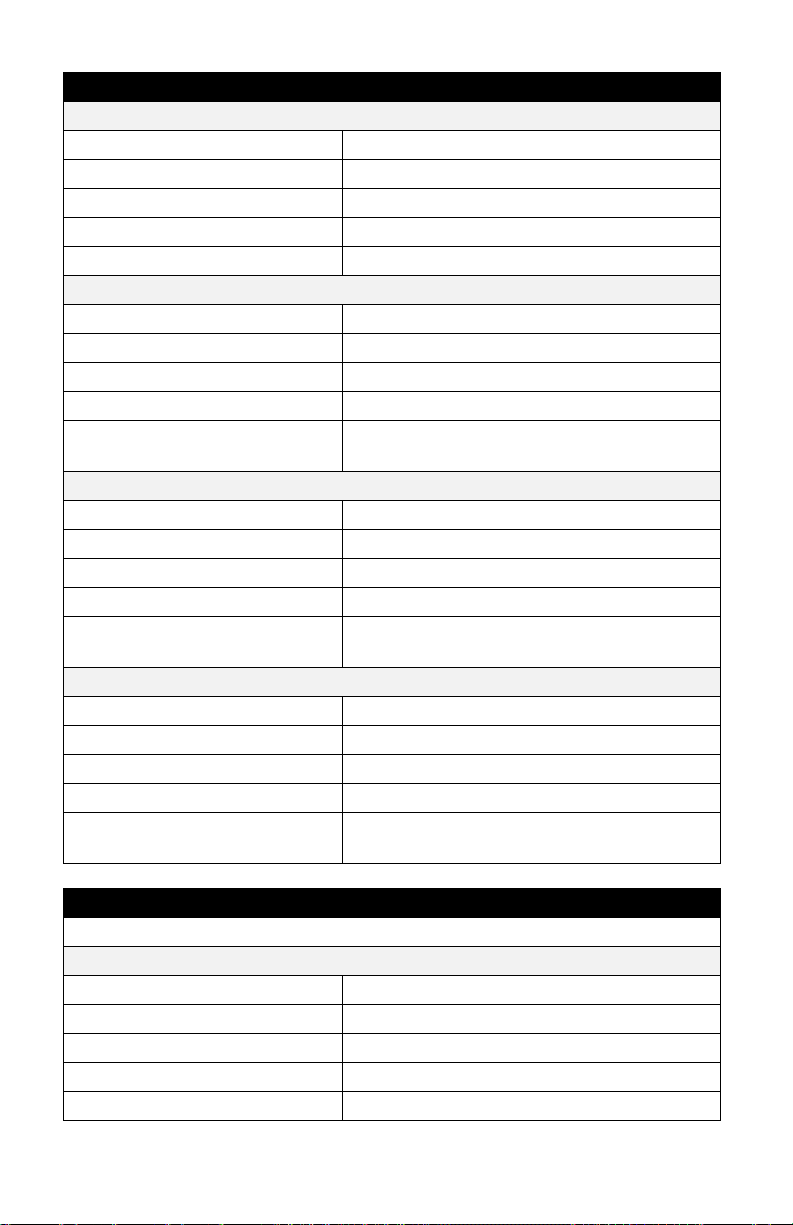
74 Q-Trak™ XP IAQ Monitor Model 7585
Installed Sensors
Carbon Dioxide
Sensor Type ..............................
Nondispersive Infrared (NDIR)
Range .......................................
0 to 5000 ppm
Accuracy ...................................
± 50 ppm
Resolution .................................
1 ppm
Response Time (t90).................
< 40s @ 20°C ambient
Temperature
Sensor Type ..............................
Thermistor
Range .......................................
32 to 140°F (0 - 60°C)
Accuracy ...................................
± 1.0°F (0.5°C)
Resolution .................................
0.1°F (0.1°C)
Response Time (t90).................
< 15 seconds to 90% of the actual
temperature
Relative Humidity
Sensor Type ..............................
Capacitive
Range .......................................
0 to 100% RH
Accuracy ...................................
± 3% RH
Resolution .................................
0.1 % RH
Response Time (t63).................
8 Seconds to 63% of the actual relative
humidity
Barometric Pressure
Sensor Type ..............................
Piezoresistive
Range .......................................
7.7 to 37.2 in hg (196.0 to 945.0 mmHg)
Accuracy ...................................
±0.12 in. Hg (±3.0 mmHg)
Resolution .................................
0.01 in. Hg (0.1 mmHg)
Response Time (t63).................
>2 seconds to 63% of the actual
barometric pressure
Optional Gas Sensors
All sensors are pre-calibrated and include a certificate of calibration.
Carbon Dioxide (CO2) sensor - P/N 801399
Sensor Type ..............................
NDIR (Non-dispersive Infrared)
Range .......................................
0 - 5000 ppm
Accuracy
2 ....................................................
± 50 ppm
Resolution .................................
1 ppm
Response Time (t90).................
< 40s @ 20°C ambient
Page 89
Operation and Service Manual 75
Optional Gas Sensors
Carbon Monoxide (CO) sensor - P/N 801401
Sensor Type ..............................
Electrochemical
Range ........................................
0 to 400 ppm
Accuracy ...................................
± 2% of reading ± 1 ppm
Resolution .................................
0.1 ppm
Response Time (t90) .................
< 30 seconds from zero to 10 ppm
TVOC Sensor (ppb) sensor - P/N 801408
Sensor Type ..............................
PID (Photo Ionization Detector)
Range ........................................
0 to 20 ppm
Accuracy
1,2 .................................................
± 3% of reading ± 1 ppm
Resolution .................................
0.01 ppm
Response Time (t90) .................
<3 seconds
TVOC Sensor (ppm) sensor - P/N 801407
Sensor Type ..............................
PID (Photo Ionization Detector)
Range ........................................
0 to 2000 ppm
Accuracy
1,2 .................................................
0-20 ppm: ±3% of reading ± 1ppm;
21-250 ppm: ± 1ppm;
251-2000 ppm: ± 20 ppm
Resolution .................................
0.1 ppm
Response Time (t90) .................
<3 seconds
Formaldehyde (CH2O) sensor - P/N 801409
Sensor Type ..............................
Electrochemical
Range ........................................
0-10 ppm
Accuracy ...................................
± 0.3 ppm
Resolution .................................
0.01 ppm
Response Time (t90) .................
< 90 seconds
Ozone (O3) sensor - P/N 801406
Sensor Type ..............................
Electrochemical
Range ........................................
0 to 20 ppm
Accuracy ...................................
± 0.3 ppm
Resolution .................................
0.01 ppm
Response Time (t90) .................
< 80 seconds from zero to 1 ppm
Page 90
76 Q-Trak™ XP IAQ Monitor Model 7585
Optional Gas Sensors
Chlorine (CL) sensor- P/N 801400
Sensor Type ..............................
Electrochemical
Range .......................................
0 to 20 ppm
Accuracy ...................................
± 0.3 ppm
Resolution .................................
0.01 ppm
Response Time (t90).................
< 60 seconds from zero to 10 ppm
Ammonia Sensor (NH3) sensor - P/N 801403
Sensor Type ..............................
Electrochemical
Range .......................................
0 to 100
Accuracy ...................................
± 1 ppm
Resolution .................................
0.1 ppm
Response Time (t90).................
< 45 seconds
Hydrogen Sulfide (H2S) sensor - P/N 801402
Sensor Type ..............................
Electrochemical
Range .......................................
0 to 50 ppm
Accuracy ...................................
± 0.5 ppm
Resolution .................................
0.01 ppm
Response Time (t90).................
< 60 seconds from zero to 2 ppm
Nitric Oxide (NO) sensor - P/N 801404
Sensor Type ..............................
Electrochemical
Range .......................................
0 to 20 ppm
Accuracy ...................................
± 0.2 ppm
Resolution .................................
0.1 ppm
Response Time (t90).................
< 25 seconds from zero to 2ppm
Nitrogen Dioxide (NO2) sensor - P/N 801405
Sensor Type ..............................
Electrochemical
Range .......................................
0 to 20 ppm
Accuracy ...................................
± 0.5 ppm
Resolution .................................
0.01 ppm
Response Time (t90).................
< 80 seconds from zero to 2ppm
t90: Time to achieve 90% of the actual concentration
1
TVOC accuracy statement based on factory testing with isobutylene
2
CO2 and TVOC accuracies based on density correction activated
Page 91

77
APPENDIX B
Definitions
Out-of-Range
(Calibration)
An Out-of-Range error during the calibration of a
sensor means the sensor’s offset or calibration
slope adjustment has drifted outside of the TSI®
recommended specification for continued use.
Sensor should be replaced or sent to TSI® for
recalibration.
Test Duration
The time over which the data will be logged while
in Continuous Save mode. The test duration
can be set from 1 second to 99 hours:
59 minutes: 59 seconds.
Sample Interval
The sample interval is the time period where data
is collected and averaged to produce a single
value. For example, if the sample interval is set
to 1 minute, each 1 second sample will be
averaged over the minute and result in a single
value. The sample interval can be set from
1 second to 99 hours: 59 minutes: 59 seconds.
However, the sample interval cannot be greater
than the test duration.
Time Constant
The time constant is an averaging period for the
readings shown on the display. It is used to
dampen fluctuations in the measurement to
make it easier to read. If there are significant
fluctuations in the readings, a longer time
constant setting will reduce the fluctuations. The
display will update ever second; however, the
displayed reading will be the average over the
time constant period. For example, if the time
constant is 5 seconds, the display will update
every second, but the displayed reading will be
the average of the last 5 seconds.
Page 92

78 Q-Trak™ XP IAQ Monitor Model 7585
(This page intentionally left blank)
Page 93

Page 94

TSI Incorporated – Visit our website www.tsi.com for more information.
USA Tel: +1 800 680 1220
UK Tel: +44 149 4 459200
France Tel: +33 1 41 19 21 99
Germany Tel: +49 241 523030
India Tel: +91 80 67877200
China Tel: +86 10 8219 7688
Singapore Tel: +65 6595 6388
P/N 6013907 Rev A ©2020 TSI Incorporated Printed in U.S.A.
 Loading...