

Page 1

iiCCoonnnneecctt AAcccceessss 662244
TTeecchhnniiccaall RReeffeerreennccee //
UUsseerr GGuuiiddee
Page 2

Copyright
Copyright© 2004 OPEN Networks Pty Ltd. All rights reserved. The content of this manual is subject to change
without notice. The information and messages contained herein are proprietary to OPEN Networks Pty Ltd. No part
of this manual may be translated, transcribed, reproduced, in any form, or by any means without prior written
permission by OPEN Networks Pty Ltd.
Disclaimer
For content and procedures available in this document, OPEN Networks Pty Ltd does not warrant or assume any
legal liability or responsibility for the accuracy, completeness, or usefulness of any information, apparatus, product,
or process disclosed.
Rev.: 1.06
Date Released: Nov. 24th, 2004
2
Page 3

Table Of Contents
Introduction................................................................................5
System Requirements ...............................................................5
Web Browser Support: ................................................................................5
Your 624 At A Glance.................................................................6
Ports And Buttons........................................................................................6
Reset................................................................................................................................7
Front LED Panel..........................................................................................8
Installing Your 624.....................................................................9
Before You Begin.....................................................................11
Configuring Your Ethernet Network Card..................................................11
For Windows® 98 Second Edition / Windows® Me.........................................................11
For Windows® 2000 / Windows® XP..............................................................................12
Setting Up Your 624.................................................................13
Default Settings.........................................................................................13
Log Into Your 624......................................................................................14
Quick Start Tab ........................................................................15
Setup Tab..................................................................................16
LAN Set Up................................................................................................17
To Enable DHCP ...........................................................................................................17
Management IP.........................................................................................19
Wide Area Network (WAN) Setup..............................................................21
Connection Types......................................................................................22
PPPoE Connection Type Set Up:..................................................................................22
PPPoA Connection Type Set Up:..................................................................................25
Bridged Connection Type Set Up:.................................................................................28
Static Connection Type Set Up:.....................................................................................31
DHCP Connection Type Set Up: ...................................................................................34
Classical IP Over ATM (CLIP) Connection Set Up........................................................36
Modify An Existing Connection..................................................................37
Modem Set Up...........................................................................................37
3
Page 4

Advanced Tab ..........................................................................39
UPnP.........................................................................................................39
SNMP........................................................................................................41
IP QoS.......................................................................................................43
LAN Clients................................................................................................ 47
MAC Address Filters..................................................................................48
Multicast ....................................................................................................50
Static Routing............................................................................................52
Dynamic Routing.......................................................................................54
Firewall......................................................................................56
Port Forwarding.........................................................................................56
Access Control ..........................................................................................59
DMZ Configuration ....................................................................................61
IP Filters ....................................................................................................62
Tools .........................................................................................64
System Commands...................................................................................65
User Management.....................................................................................66
Update Firmware.......................................................................................67
Ping Test ................................................................................................... 68
Modem Test...............................................................................................69
Status........................................................................................71
Network Statistics......................................................................................72
Connection Status.....................................................................................73
DHCP Clients ............................................................................................74
Modem Status ...........................................................................................75
Product Information...................................................................................76
System Log................................................................................................77
Index..........................................................................................78
4
Page 5

Introduction
Congratulations on the purchase of your 624. Fully-featured, it is the perfect high-speed
ADSL Modem WAN bridge/router, specifically designed to connect your PC or LAN to the
Internet and directly connect to your local area network via a high speed 10/100 Mbps
Ethernet port.
The 624’s extensive routing and bridging functions render it a flexible and scaleable platform
for multiple users to access the Internet. Features include port forwarding and VPN passthrough, along with the ability to enable public or private Intranet solutions through a single IP
address, using its RIP v 1 / 2 routing engine or NAPT features.
The highest levels of security are implemented in the 624, including Stateful Packet
Inspection firewall and DMZ support for a full suite of security options against malicious
intruders.
The 624 is fully compatible with all PCs which support an Ethernet interface and are running
a TCP/IP protocol stack. So, plug in the 624 (refer to the Quick Start Guide), configure it (per
your ISP’s instructions) and enjoy fast Internet access as never before!
System Requirements
Pentium® MMX 233MHz or greater computer, installed with the following:
CD-ROM drive;
Ethernet card installed with TCP/IP Protocol (required only if you are connecting to
the Ethernet port of your router);
OS independent for Ethernet.
Web Browser Support:
Microsoft Internet Explorer 4.0 (or later versions);
Netscape® Navigator 3.02 (or later versions).
5
Page 6
Your 624 At A Glance
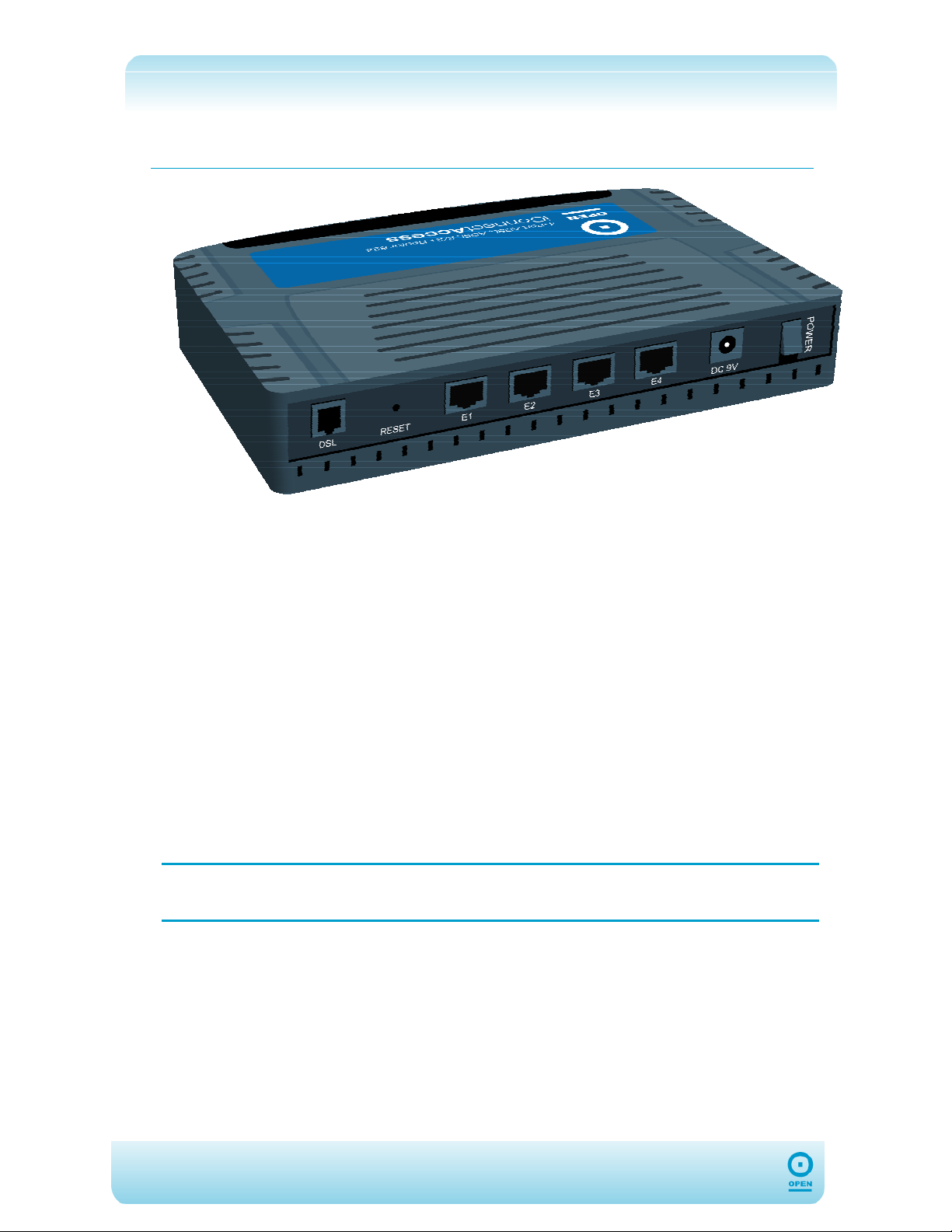
The 624 has different ports and LEDs. The following list details these:
Ports And Buttons
ADSL
The ADSL jack (RJ-11) of the 624 connects to the ADSL port of your line filter. (ADSL Line)
ETHERNET
The 10/100 Base-T Ethernet jack (RJ-45) of the 624 connects to the Ethernet LAN port of
your computer.
RESET
This button resets your 624 to factory default settings. (All customized settings will be lost
when you perform a reset.)
DC
The DC port of the 624 connects to mains power. Remember to use only the power cable
supplied with your 624, and ensure you switch the power switch to the ON position.
NOTE:
As each of the cables is connected, the corresponding LED will light up
on the front of the 624.
6
Page 7

Reset
Reset And Restore To Factory Defaults:
The Restore To Factory Defaults feature will reset the 624 to its factory default configuration.
If configuration details in the router are changed, or following a firmware upgrade, you may
lose the ability to configure it via the web interface. In order to restore this functionality, you
may need to reset it to factory defaults.
To Reset The 624:
Ensure that the 624 has been powered on for a minimum of 10 seconds.
Use a blunt implement, such as a pencil or paperclip to press the reset button for
10 seconds, then release it.
NOTE:
During this time the reset is in progress. Do NOT power the 624 off whilst it
resets.
The 624 will be reset to its factory defaults and once the indicator lights have returned to
green (non-blinking), the reset is complete.
7
Page 8
Front LED Panel
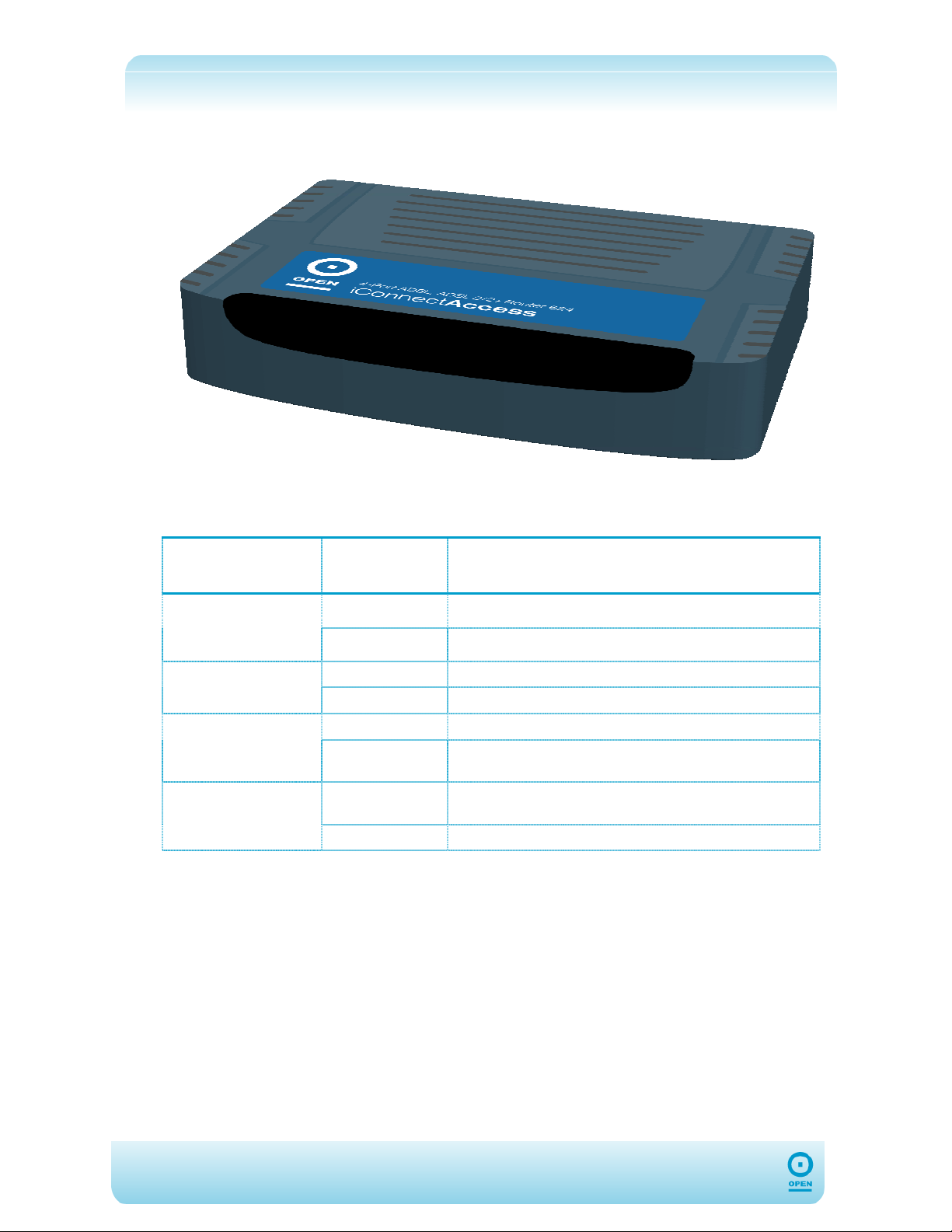
The following table displays the LED Status of each of the 624’s LEDs and the definitions of
each:
ADSL Front Panel
LED
PPP
PWR
DSL
ETH/ACT
LED Status Definition
Steadily Lit Up PPP connection to 624 is established.
Flickering N/A
Steadily Lit Up Power is supplied to the 624.
Flickering N/A
Steadily Lit Up ADSL connection is established.
Flickering
Steadily Lit Up
Flickering Ethernet is transmitting / receiving data.
Router is trying to establish connection with ADSL
Service Provider.
624 Ethernet cable is properly connected to Computer
Ethernet port.
8
Page 9
Installing Your 624
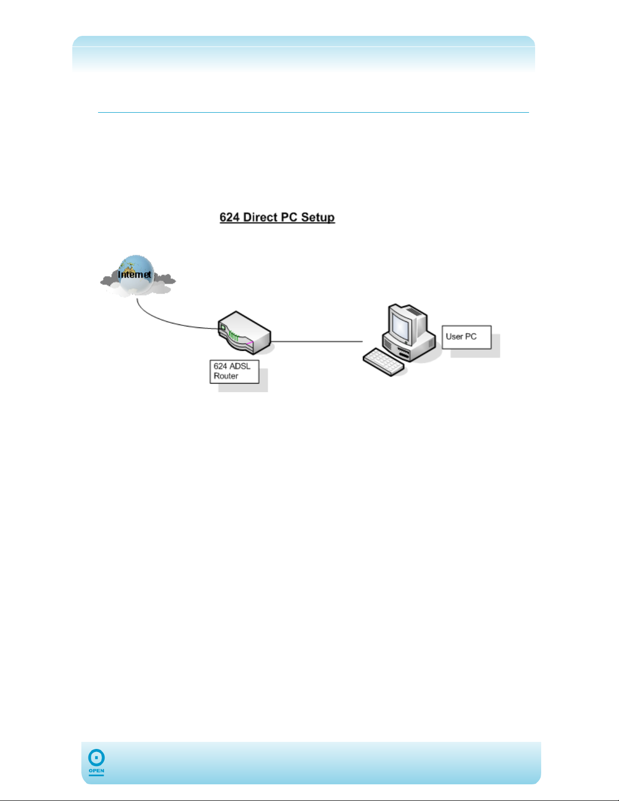
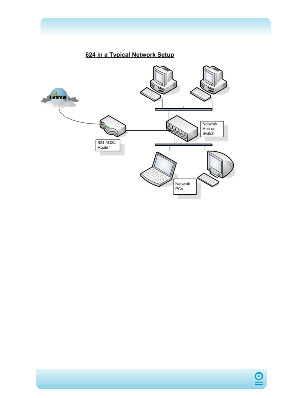
step 1 Locate an optimum location for the 624.
step 2 Connect the AC Power Adapter to mains power.
step 3 Now that the hardware installation is complete, you may need to configure
Ethernet driver. Proceed to Configuring Your Ethernet Network Card for more
information.
9
Page 10
10
Page 11

Before You Begin
Configuring Your Ethernet Network Card
Before you can use your iConnect Access 624, you may need to configure drivers for the
Ethernet ports on the router.
For Windows® 98 Second Edition / Windows® Me
Please note that these instructions may vary, depending on whether this is the
NOTE:
step 1 From your Windows desktop, click Start > Settings > Control Panel.
step 2 From the Control Panel window, double-click the Network icon.
step 3 From the Network screen, highlight the Configuration tab to make it active.
step 4 From the The following network components are installed area of
step 5 From the TCP/IP Properties screen, click the IP Address tab to make it
step 6 Highlight the Obtain an IP Address Automatically radio button, and
step 7 Ensure that the 624 is powered on. Restart your system when prompted.
first time you are configuring your Ethernet Driver in Windows. Those below
are for first-time configurations.
the window, select TCP/IP-> xxx where xxx refers to the model of the
Ethernet card connected to your ADSL Router, and click Properties.
active.
click OK to save the settings.
11
Page 12

For Windows® 2000 / Windows® XP
Please note that these instructions may vary, depending on whether this is the
NOTE:
Windows® 2000:
step 1 From your Windows desktop, click Start > Control Panel.
step 2 From the Control Panel window, double-click the Network Connections
step 2 From the Network Connections window, right-click on the Local Area
step 3 Proceed from step 3 in the Windows XP Ethernet Driver Configuration
Windows® XP:
first time you are configuring your Ethernet Driver in Windows. Those below
are for first-time configurations.
icon.
Connection icon and select Properties.
Procedure below.
NOTE:
Instructions are based on the default Start menu option.
step 1 From your Windows desktop, click Start > Control Panel.
step 2 From the Network Connections window, right-click on the Local Area
Connection icon that reflects the model of the Ethernet Card connected to
your 624, and click Properties.
step 3 In the Properties window of the LAN connected, ensure that the Connect
Using field indicates the model of the Ethernet Card connected to your 624.
This is important especially if you have more than one Local Area Connection
NOTE:
icon displayed in the Network Connections window. Ensure that you have
selected the correct one.
step 4 From the This connection uses the following items: area of the
Properties window, select Internet Protocol (TCP/IP) and click
Properties.
step 5 From the General tab of the Internet Protocol (TCP/IP) Properties
window, highlight the Obtain an IP Address Automatically radio
button, and click OK.
step 6 Click OK again to close the dialog.
step 7 Ensure that your 624 is powered on. Restart your system when prompted.
12
Page 13
Setting Up Your 624
This section will guide you through your 624’s configuration via the web interface. The 624 is
shipped with a standard PPP configuration.
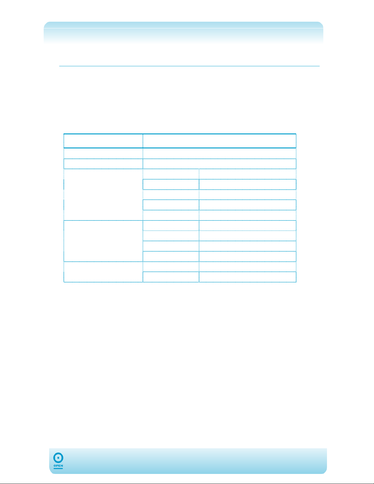
Default Settings
The following table lists the default settings for your 624. These settings may change
depending on your DSL Provider / ISP. Please check with your DSL Provider / ISP for more
information.
Setting Default Value
Login Username
Login Password
Quickstart
VCI
DHCP Configuration
Management IP
root
0P3N
Username
Password
Protocol
VPI
Server On Enabled
Start IP
End IP
Lease Time
IP Address
Netmask
<blank>
<blank>
PPPoE
8
35
192.168.1.100
192.168.1.200
7 days
192.168.1.254
255.255.255.0
13
Page 14
Log Into Your 624
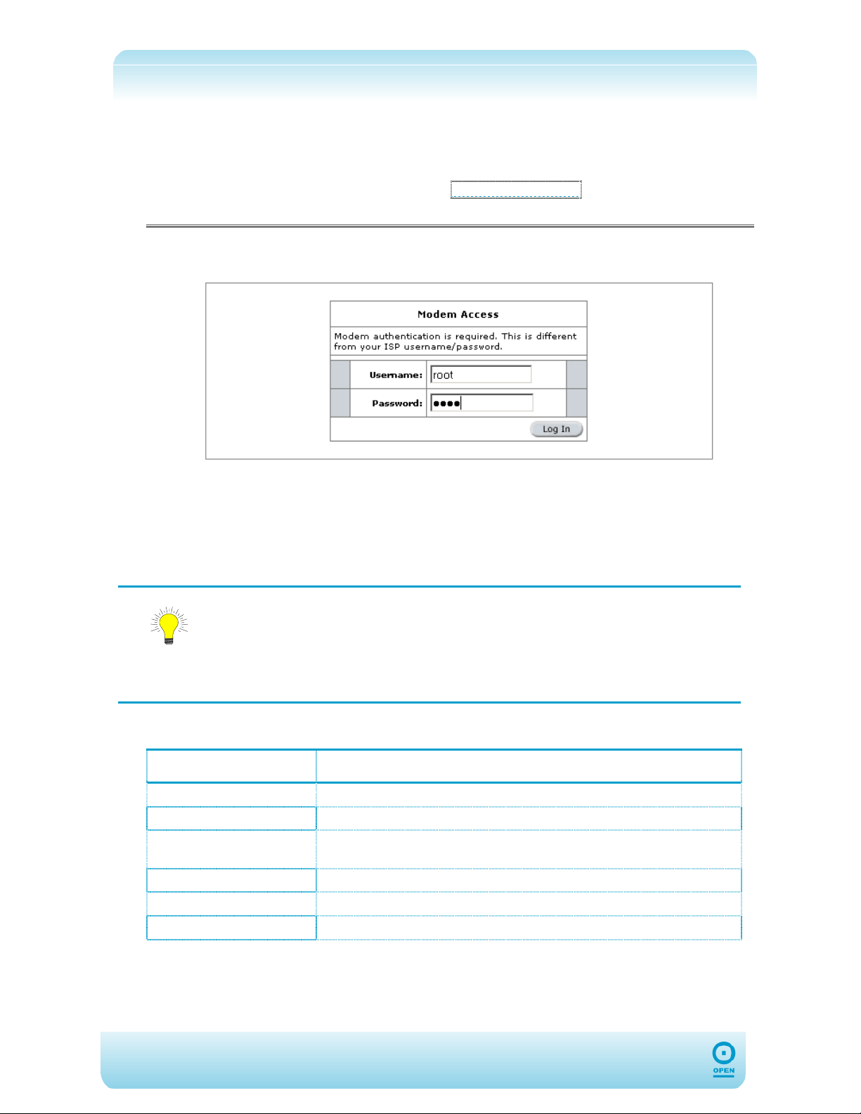
To Configure Your 624:
step 1 Open your web browser and enter
then press Enter.
http://192.168.1.254 in the Address bar,
step 2 In the Modem Access screen, enter root (case sensitive) in the Username
field and in the Password field, enter 0P3N (case sensitive).
step 3 Click Log In.
Ensure your computer is configured for DHCP mode and that proxies are
disabled in your browser.
You must also ensure that JavaScript support is enabled in browser settings, so
that the browser does not display a login redirection screen. Finally, if any
TIP:
screen other than the Login screen appears, you may need to delete your
temporary Internet files. (ie, basically flush the cached web pages).
Logging in allows you to access the 624’s web interface. This consists of the following six
tabs that provide all the options you need to configure your 624:
Tab Function
Quick Start
Setup
Advanced
Tools
Status
Help
Configuration of Log In settings
Configuration of LAN and WAN Settings
Configuration of advanced options within the 624 such as security,
routing and filtering.
Access tools and diagnostics to assist in debugging.
Obtain the status of the 624.
View the extensive online help
14
Page 15
Quick Start Tab
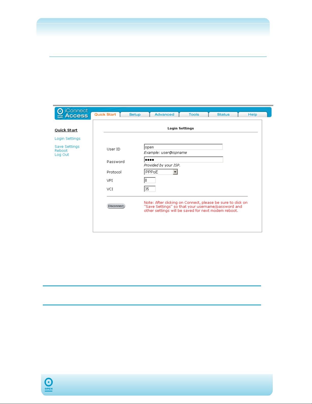
After you have logged in, the first screen to appear will be the Login Settings screen,
which is the only menu item of the Quick Start tab. This is where you will set up your
DSL Provider / ISP user name and password, and your connection type protocol.
By default your 624 has been pre-configured to the PPP settings for your DSL Provider / ISP,
so you should only need to enter your DSL Provider / ISP username and password to make
a connection to the Internet.
step 1 From the Login Settings screen, in the User ID field, enter your ISP
Username.
step 2 In the Password field, enter your DSL Provider / ISP password.
step 3 From the Protocol drop-down list, select the connection type protocol used by
your ISP.
step 4 Click Connect.
NOTE:
After clicking Connect, ensure that you Save Settings to register the
username / password or any other changes.
15
Page 16
Setup Tab
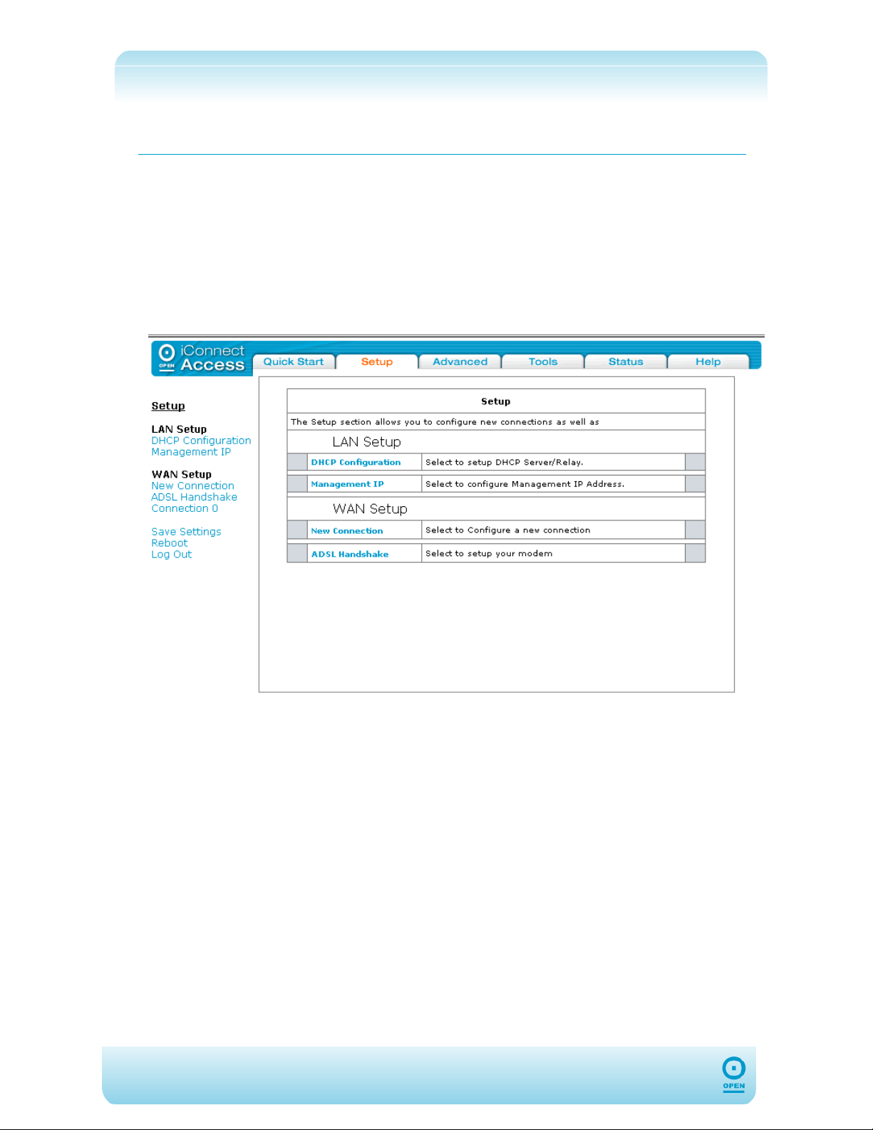
The Setup tab allows you to set up the LAN and WAN sides of your networks, including:
DHCP Configuration;
Management IP;
New WAN Connections;
Modem Configuration.
Accessing The Setup Main Screen:
From the Quick Start page, click Setup. The following screen appears:
The Setup screen consists of two set up subsections: LAN Setup and WAN Setup. From
here you can select the LAN and WAN Settings you wish to configure by clicking the
appropriate links.
16
Page 17
LAN Set Up
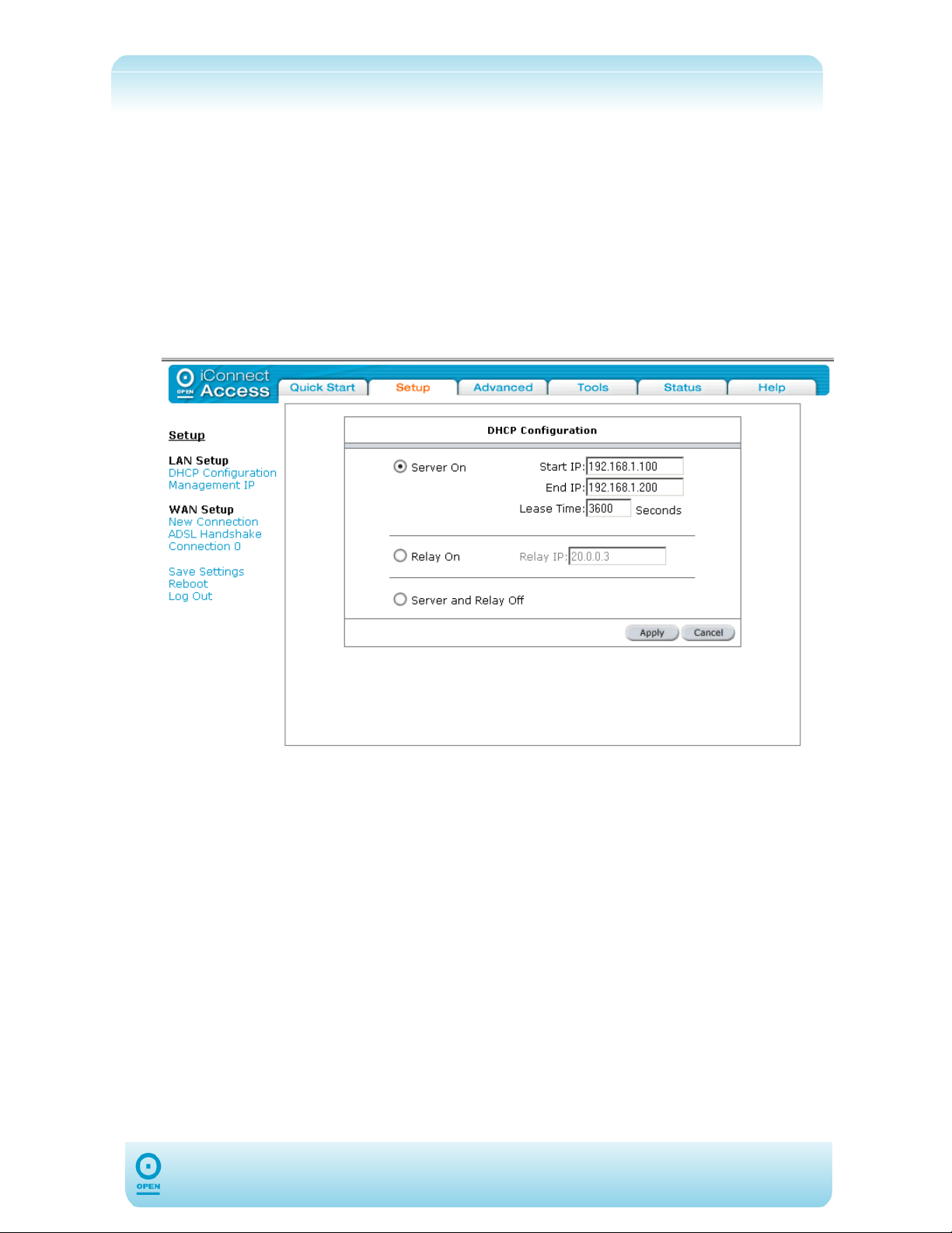
By default, your 624 has the DHCP server (LAN side) enabled. If you already have a DHCP
server running on your network, you must disable one of them; if you connect a second
DHCP server into the network, you will experience network errors and the network will not
function normally.
To Enable DHCP
step 1 From the main screen, click Setup.
step 2 Under the LAN Setup menu, select DHCP Configuration. The following
screen appears.
step 3 Highlight the Server On radio button.
step 4 Enter the Start IP Address. This address is the beginning of the range
from which the DHCP Server starts issuing IP addresses.
step 5 Enter the End IP Address.
step 6 Click Apply to save the changes temporarily.
step 7 Click Save Settings to save the changes permanently.
17
Page 18
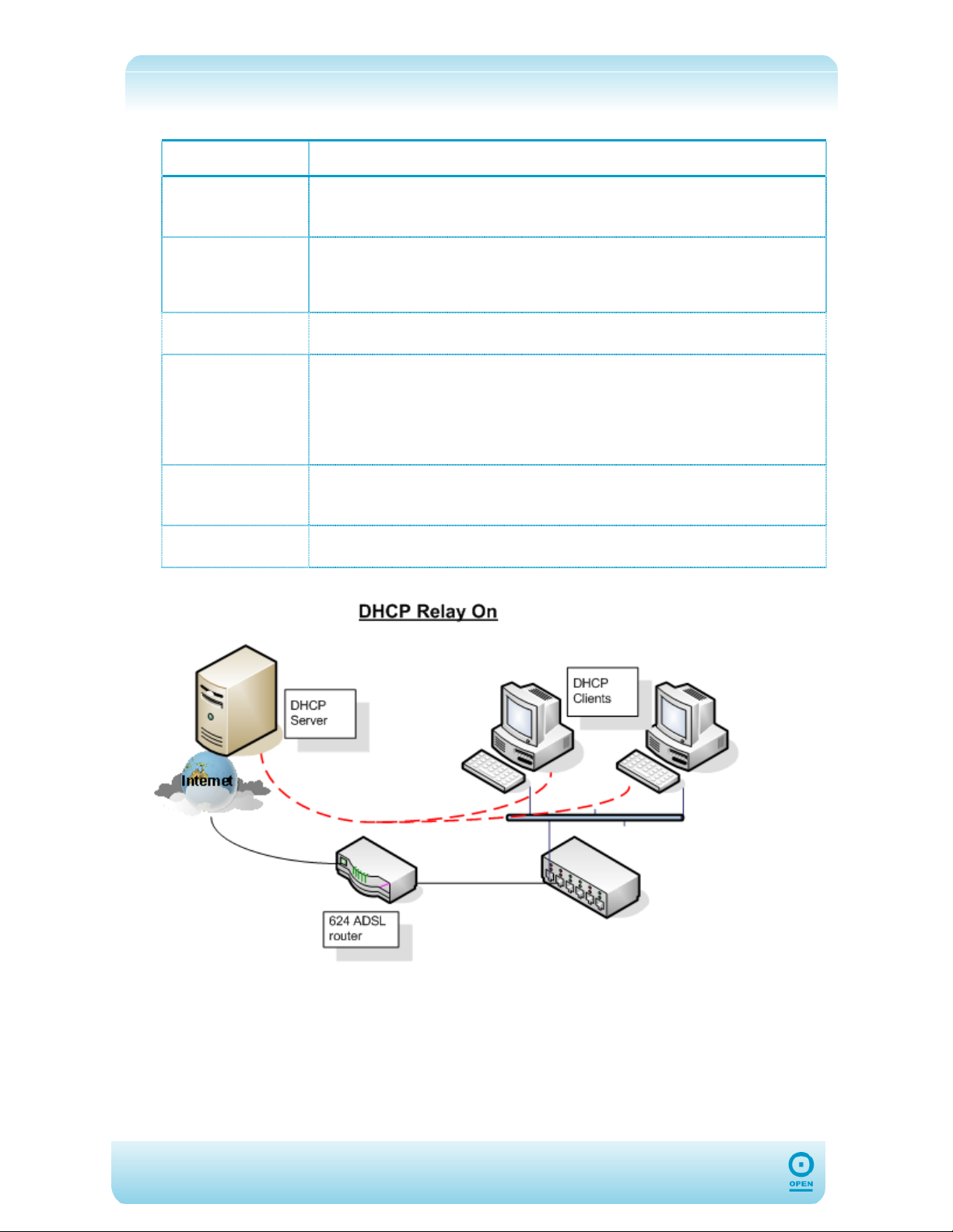
The following table lists the DHCP Configuration screen fields and their definitions:
Field Description
Server On
Start IP
End IP
Lease Time
Relay On
Server and
relay Off
Highlighting the Server On radio button turns on the DHCP server. This will
need to be disabled if a DHCP server is already running on the LAN. The DHCP
Server is set to on by default.
This address is the beginning of the range from which the DHCP Server starts
issuing IP addresses. You need to ensure the 624 Management IP address and
any statically-defined addresses are not within the DHCP start and end address
ranges. The default Start IP address is 192.168.1.100.
This is the end of the DHCP Server IP address range. The default End IP is
192.168.1.200.
The Lease Time is the amount of time a LAN PC will hold the IP address. The
IP Address will automatically renew after this time has elapsed. If the LAN PC
does not renew the address after the lease period the lease information will be
removed from the DHCP database. This database can be viewed under
Tools> DHCP Clients. The lease time is in units of seconds; the default
value is 604800 seconds (7 days).
Highlighting the Relay On radio button configures the 624 to forward the DHCP
request to a remote DHCP server. Enter the remote DHCP server address in
the Relay IP field.
This will disable the 624’s DHCP server and relay functionality.
18
(Example of a DHCP Relay configuration)
Page 19
Management IP
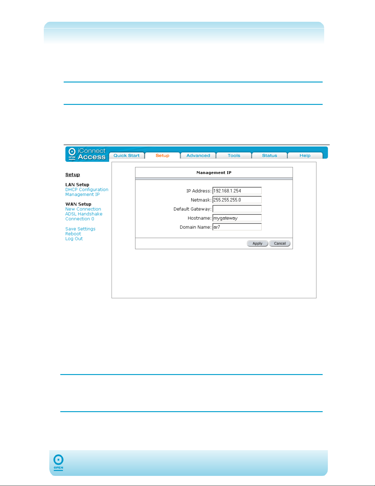
The Management IP area of the web interface allows you to configure the LAN IP Address
details for the 624.
NOTE:
If you change this address from the default, you will need to reconnect using
your new IP Address.
To Change The 624 IP Address:
step 1 From the main screen, click Setup.
step 2 From the LAN Setup menu, click Management IP. The following appears:
step 3 Enter the IP Address in the IP Address field as required.
step 4 Enter the netmask in the Netmask field as required.
step 5 Enter the default gateway as provided by your DSL Provider / ISP in the
Default Gateway field.
step 6 Enter an alphanumeric Hostname in the Hostname field. This cannot contain
spaces.
step 7 Enter the Domain Name in the Domain Name field. This cannot contain spaces.
The Domain Name is used in conjunction with the Hostname to identify the 624
NOTE:
step 8 Click Apply to save the changes temporarily.
step 9 Click Save Settings from the menu list to make the change permanent.
uniquely. To access the 624’s web pages you can type the IP 192.168.1.254 or
mygateway.ar7 in the web browser. Using the Hostname in the browser
requires the workstation to have its DNS server set to the 624.
19
Page 20
The following table lists the Management IP screen fields and their definitions:
Field Description
The Default IP Address for the 624 is 192.168.1.254. Its Subnet Mask
IP Address
Netmask
Default Gateway
is 255.255.255.0, and this allows you to support 254 users. If you wish to
support a larger number of users, you can alter the Subnet Mask. However, if
you do, remember the DHCP Server is defaulted to give out 101 IP Addresses.
A mask used to determine the subnet to which an IP address belongs. This is
the Subnet Mask that will be assigned to the Management interface of the 624.
The default gateway is a host to which local computers send data that is
destined for a non-local machine. On the 624, configure the default gateway
address here to reach all computers that are not on the same local IP subnet.
Hostname
Domain Name
This is the assigned hostname for the 624. The Hostname can be any
alphanumeric word that does not contain spaces.
The Domain Name is used in conjunction with the Hostname to uniquely identify
the 624. Domain Names always have 2 or more parts, separated by dots. The
part on the left is the most specific, and the part on the right is the most general.
Usually, all of the hosts on a given Network will have the same part as the righthand portion of their Domain Names.
20
Page 21

Wide Area Network (WAN) Setup
Before the router will pass any data between the LAN and WAN interfaces, the WAN side of
the 624 must be configured. Depending on your DSL service provider or ISP, you will need
some (or all) of the information outlined below before you can properly configure the WAN.
The following table lists all DSL requirements:
DSL Requirement Comment
Line
VPI and VCI
Encapsulation and
Multiplexing
Training Mode
PPPoA / PPPoE Requirement
Username
Password
Static Type Requirement
The VPI (Virtual Path Identifier) and the VCI (Virtual Channel
Identifier) define the virtual path settings for the ADSL
connection between you and your ISP. By default, these
settings are pre-configured for 8/35 in your 624. If you wish
to change them, please ensure you obtain the correct
VPI/VCI setting details form your ISP.
For PPPoA, Static, Bridge, DHCP and CLIP authentication
types, you may have to define the encapsulation parameters.
The 624 has two options for encapsulation: LLC
encapsulation and VCMux. The default encapsulation type
for the 624 is LLC. If you wish to change these settings,
please ensure you obtain the correct encapsulation setting
details form your ISP.
The default is MMODE, and this enables your 624 to tune into
the ADSL services in Australia automatically. Do not change
this parameter.
Your username is required for authentication for your Internet
service.
Your username is required for authentication for your Internet
service.
DSL Fixed Internet IP
Address
Subnet Mask
Default Gateway
Primary DNS IP Address
As multiple users can use the 624, different profiles must be set up for different connections.
The 624 supports the following connection types:
PPPoE
PPPoA
Bridged;
Static;
DHCP;
CLIP.
21
Page 22
Connection Types
Your 624 can support up to 8 unique virtual connections. If you have multiple virtual
connections, you may need to utilize the static and dynamic routing capabilities of the router
to pass data correctly.
PPPoE Connection Type Set Up:
Computers connected to the Internet via ADSL do so through an Ethernet link. As such,
plain TCP/IP has been used, with no additional protocols. PPP (Point-to-Point Protocol)
provides secure login, and traffic metering among other advanced features. PPPoE (PPP
over Ethernet) was designed to bring the security and metering benefits of PPP to Ethernet
connections such as DSL.
PPPoE allows ADSL users to be authenticated by the ISP’s Radius authentication systems.
Most broadband connections are Ethernet, hence Point-to-Point Protocol over Ethernet. It
also allows for ISPs to provide multiple services over multiple PPP sessions, ie, rated
services, broadband specific content (movies, etc.), metered services, etc.
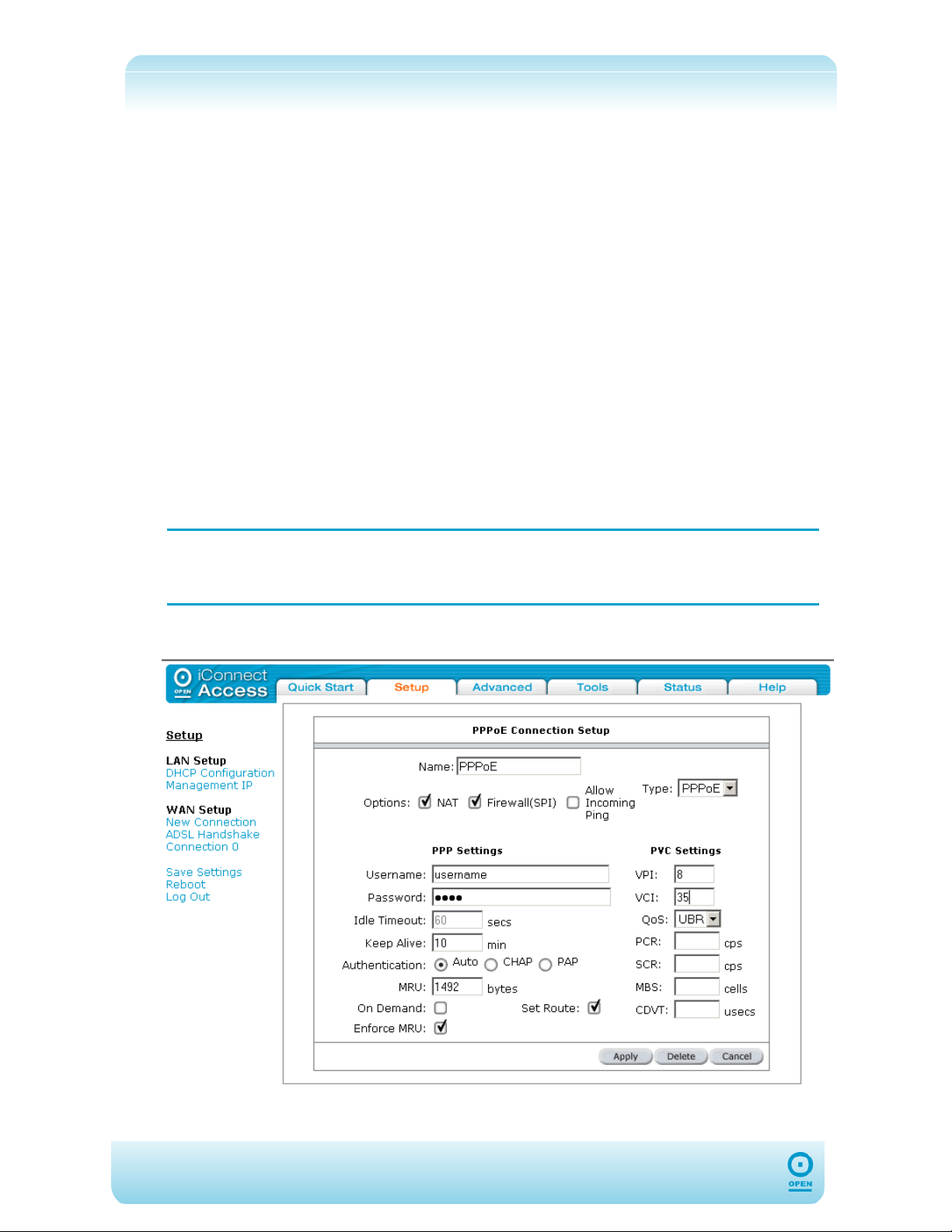
To Configure PPPoE:
step 1 From the main screen, click Setup.
step 2 From the WAN Setup menu, click New Connection.
The default PPPoE connection setup screen appears.
If you need to use the VPI and VCI values in an existing connection, you will
NOTE:
step 3 From the Type drop-down list, select PPPoE.
need to open it and edit the setting. It is not possible to have more than one
connection using the same VPI/VCI values.
The following is displayed:
22
Page 23

step 4 Enter a unique name for your PPPoE connection in the Name field. The name
must not have spaces and cannot begin with numbers.
step 5 Check the NAT and Firewall checkboxes beside the Options field.
step 6 Enter your DSL Provider / ISP username and password in the Username and
Password fields.
step 7 Enter the DSL Provider / ISP-provided VPI and VCI settings.
step 8 Click the Apply button to save the connection temporarily.
step 9 Click Save Settings from the menu list to make the change permanent.
23
Page 24

The following table lists the PPPoE Connection type fields and describes each of the options:
Field Description
Network Address Translation is a feature that enables you to use private IP
NAT
addresses on your PC or your LAN. This is set to Enabled by default for
standard operation.
Firewall (SPI)
Allow Incoming
Ping
Username
Password
On-Demand
Idle Timeout
Keep Alive
Authentication
Set Route
MRU
Select to enable firewalling on this connection. This is set to Enabled by default
for standard operation.
Ping is a protocol used mainly for monitoring the connectivity between IP
devices. Enabling this feature allows remote devices to use ping to check
connectivity to your device. You may need to enable this for monitoring
purposes. This is set to Disabled by default for standard operation.
The Username for your ISP account.
The Password for your ISP account.
If selected, this enables on-demand connectivity to the Internet. Your Internet
connection will be disconnected if no activity is detected after the specified
timeout value. This is unchecked by default.
This specifies that the PPPoE connection should disconnect if the link detects no
activity for x seconds. If you wish to ensure the link remains always connected,
enter 0 in this field. This option will only be available when the On-Demand
option is checked.
When the On-Demand option is disabled, this value specifies the time to wait
without connection to your provider before terminating the connection. If you
wish to ensure the link remains always active, enter 0 in this field. This is set to
0 by default.
This defines the authentication protocol for your ISP. This is set to Auto by
default.
Check this checkbox to make this the default connection.
Enter the Maximum Receive Unit for the DSL connection. This is a negotiated
value that specifies the packet size of the data being sent from the DSL provider.
This ranges from a minimum of 128 to a maximum of 1500. The default value is
set to 1492.
Enforce MRU
VPI
VCI
QoS
24
Check this checkbox if you encounter problems accessing the Internet over a
PPPoE connection. This feature forces all TCP traffic to conform with PPP MRU
by changing the TCP Maximum Segment Size to PPP MRU. This is selected by
default.
The VPI (Virtual Path Identifier) defines the virtual path settings for the
ADSL connection between you and your ISP. The value entered here must be
supported by your ISP.
The VCI (Virtual Channel Identifier) defines the virtual channel
settings for the ADSL connection between you and your ISP. The VCI value
entered here must be supported by your ISP.
QoS defines the 624 capabilities that provide guarantee of performance such as
traffic delivery priority, speed, latency, or latency variation. Delivery of goodquality audio or video streams typically requires QoS capabilities. Three
different Quality Of Service options are available in the 624: UBR, CBR and
VBR. The QoS selected here must be supported by your ISP. By default this is
set to UBR.
Page 25
PPPoA Connection Type Set Up:
PPPOA or PPPoA, Point-to-Point Protocol (PPP) over ATM, is a network protocol for
encapsulating PPP frames in ATM AAL5. It used mainly with ADSL services and is
compliant with RFC 2364. PPP over ATM adaptation layer 5 (AAL5) – PPPoA uses AAL5 as
the framed protocol, which supports both PVC and SVC.
PPPoA was primarily implemented to support PPP sessions over the ADSL network. It relies
on RFC1483, operating in either Logical Link Control-Subnetwork Access Protocol (LLCSNAP) or VC-Mux mode. A Customer Premises Equipment (CPE) device, normally an
ADSL modem, encapsulates the PPP sessions for transport across the ADSL network and
the Digital Subscriber Line Access Multiplexer (DSLAM).
It offers standard PPP features such as authentication, encryption, and compression.
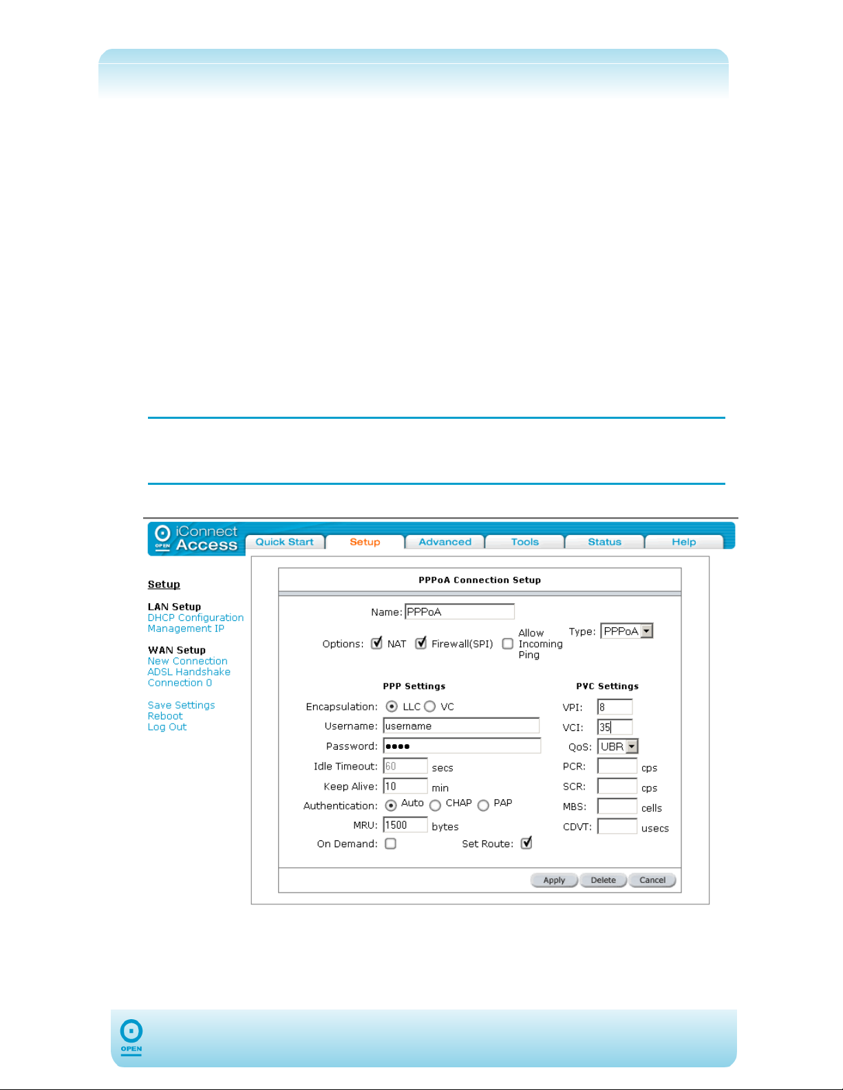
To Configure The 624 For PPPoA:
step 1 From the main screen, click Setup.
step 2 Under the WAN Setup, click New Connection.
The default PPPoE Connection type screen appears.
If you need to use the VPI and VCI values in an existing connection, you will
NOTE:
need to open it and edit the setting. It is not possible to have more than one
connection using the same VPI/VCI values.
step 3 From the Type drop-down list select PPPoA. The following appears:
step 4 Check the NAT and Firewall checkboxes beside the Options field.
step 5 Enter a unique name for the PPPoA connection in the Name field. The name
must not have spaces and cannot begin with numbers.
25
Page 26

y
step 6 Select the encapsulation type (LLC or VC) by highlighting the appropriate radio
button. If you are not sure leave this set to the default.
step 7 Enter your DSL Provider / ISP username and password in the Username and
Password fields.
step 8 Enter the VPI and VCI settings as supplied by your DSL service provider / ISP.
step 9 Click Apply to save the connection temporarily.
step 10 Click Save Settings from the menu bar to save the changes permanently.
The following table lists the PPPoA Connection Set up screen fields and describes each of
the options:
Field Description
Network Address Translation is a feature that enables you to use private IP
NAT
Firewall
Allow
Incoming Ping
addresses on your PC or LAN. This is set to Enabled by default for standard
operation.
Select to enable firewalling on this connection. This is set to Enabled by default for
standard operation.
Ping is a protocol used mainly for monitoring the connectivity between IP devices.
Enabling this feature allows remote devices to use ping to check connectivity to
your device. You may need to enable this for monitoring purposes. This is set to
Disabled by default for standard operation.
Encapsulation
Username
Password
On-Demand
Idle Timeout
Keep Alive
Set Route
MRU
LLC and VC are two different methods of encapsulating multiple sessions. This is
set to LLC by default.
LLC
VC
The username for your ISP account.
The password for your ISP account.
If selected, this enables on-demand connectivity to the Internet. Your Internet
connection will be disconnected if no activity is detected after the specified timeout
value. This is unchecked by default.
This specifies that the PPPoE connection should disconnect if the link detects no
activity for x seconds. If you wish to ensure the link remains always connected,
enter 0 in this field. This option will only be available when the On-Demand option
is checked.
When the On-Demand option is disabled, this value specifies the time to wait
without connection to your provider before terminating the connection. If you wish
to ensure the link remains always active, enter 0 in this field. This is set to 0 by
default.
Check this checkbox to make this the default connection.
Enter the Maximum Receive Unit for the DSL connection. This is a negotiated
value that specifies the packet size of the data being sent from the DSL provider.
This ranges from a minimum of 128 to a maximum of 1500. The default value is
set to 1500.
With LLC encapsulation, a link control header is added to the Ethernet
packet that identifies the protocol type (Ethernet). This allows multiple
protocols to be transmitted over the ATM Virtual Circuit.
With VC Multiplexing, no link control header is needed as the ATM Virtual
Circuit is assumed to be carrying a single protocol
VPI
26
The VPI (Virtual Path Identifier) defines the virtual path settings for the ADSL
connection between
ou and your ISP. The VPI value entered here must be
Page 27
VCI
QoS
supported by your ISP.
The VCI (Virtual Channel Identifier) defines the virtual channel settings for the
ADSL connection between you and your ISP. The VCI value entered here must be
supported by your ISP.
QoS defines 624 capabilities that provide guarantee of performance such as traffic
delivery priority, speed, latency, or latency variation. Delivery of good-quality audio
or video streams typically requires QoS capabilities. Three different Quality Of
Service options are available in the 624. These are UBR, CBR and VBR. The
QoS selected here must be supported by your ISP. By default this is set to UBR.
27
Page 28
Bridged Connection Type Set Up:
In Bridged mode, Ethernet frames are bridged over ATM Virtual Circuits. The Ethernet
frames are encapsulated using either LLC Encapsulation or VC Multiplexing. Since the
Ethernet packets are bridged, the router’s only functionality is to pass the Ethernet packets to
and from the Internet Service Provider and the local network. The IP addresses of the local
network are assigned by the ISP either statically or dynamically.
In this setting, NAT and firewall rules are disabled. This connection method makes the 624
act as a transparent hub, and passes packets across from the WAN interface to the LAN
interface transparently.
If your ISP provides a bridged service, this is the type that you should select.
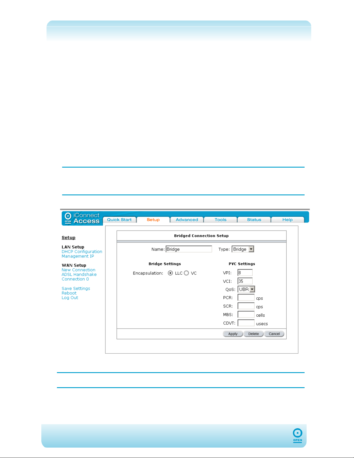
To Configure The 624 As A Bridge:
step 1 From the main screen, click the Setup tab.
step 2 From the Setup menu, under the WAN Setup, click New Connection.
The default PPPoE connection set up is displayed.
If you need to use the VPI and VCI values in an existing connection, you will
NOTE:
need to open the connection and edit the setting. It is not possible to have
more than one connection using the same VPI/VCI values.
step 3 From the Type drop-down list, select Bridge. The following screen appears:
step 4 Enter a unique name for the connection type in the Name field.
NOTE:
The Name must not contain spaces or begin with numbers.
step 5 Highlight either the LLC or VC radio button, depending on the encapsulation type
for your configuration. If you are not sure, leave this as the default.
step 6 Enter the VPI and VCI settings as supplied to you by your DSL Provider / ISP.
28
Page 29
step 7 From the QoS drop-down list, select the quality of service. Leave the default
value if you are unsure of this.
step 8 Click Apply to complete the connection.
NOTE:
The Apply button saves this connection temporarily.
step 9 Click Save Settings at the bottom of the menu to make the change
permanent.
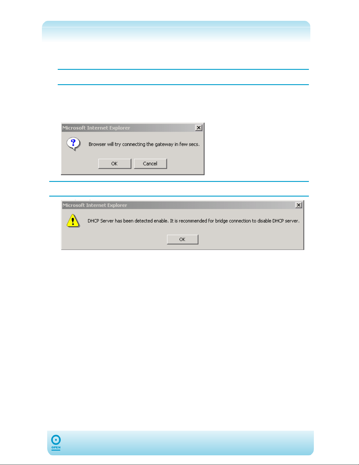
step 10 When the Browser will try connecting the gateway in a few
secs message box appears, click OK.
NOTE: If DHCP is enabled, the following warning message may appear.
step 11 Click OK and follow the instructions in the DHCP Configuration to disable the
DHCP server.
29
Page 30
The following table lists the Bridged Connection Setup screen fields and their definitions:
Field Description
Encapsulation
VPI
VCI
QoS
LLC and VC are two different methods of encapsulating multiple sessions. This
is set to LLC by default.
LLC
VC
The VPI (Virtual Path Identifier) defines the virtual path settings for the ADSL
connection between you and your ISP. The VPI value entered here must be
supported by your ISP.
The VCI (Virtual Channel Identifier) defines the virtual channel settings for the
ADSL connection between you and your ISP. The VCI value entered here must
be supported by your ISP.
QoS defines 624 capabilities that provide guarantee of performance such as
traffic delivery priority, speed, latency, or latency variation. Delivery of goodquality audio or video streams typically requires QoS capabilities. There are
three different quality of service options available in the 624. These are UBR,
CBR and VBR. The QoS selected here must be supported by your ISP. By
default this is set to UBR.
With LLC encapsulation, a link control header is added to the Ethernet
packet that identifies the protocol type (Ethernet). This allows multiple
protocols to be transmitted over the ATM Virtual Circuit.
With VC Multiplexing, no link control header is needed as the ATM
Virtual Circuit is assumed to be carrying a single protocol.
30
Page 31
Static Connection Type Set Up:
A Static Connection type is used whenever a known static IP address is assigned. The
accompanying information such as the Subnet Mask and the Gateway should also be
specified. Up to three Domain Name Server (DNS) addresses can also be specified. These
servers would enable you to have access to other web servers. The valid IP Address range
is from 0.0.0.0 to 255.255.255.255.
Static Connection Configuration:
step 1 From the main screen, click Setup , then click New Connection from the WAN
Setup menu.
The default PPPoE Connection Setup screen appears.
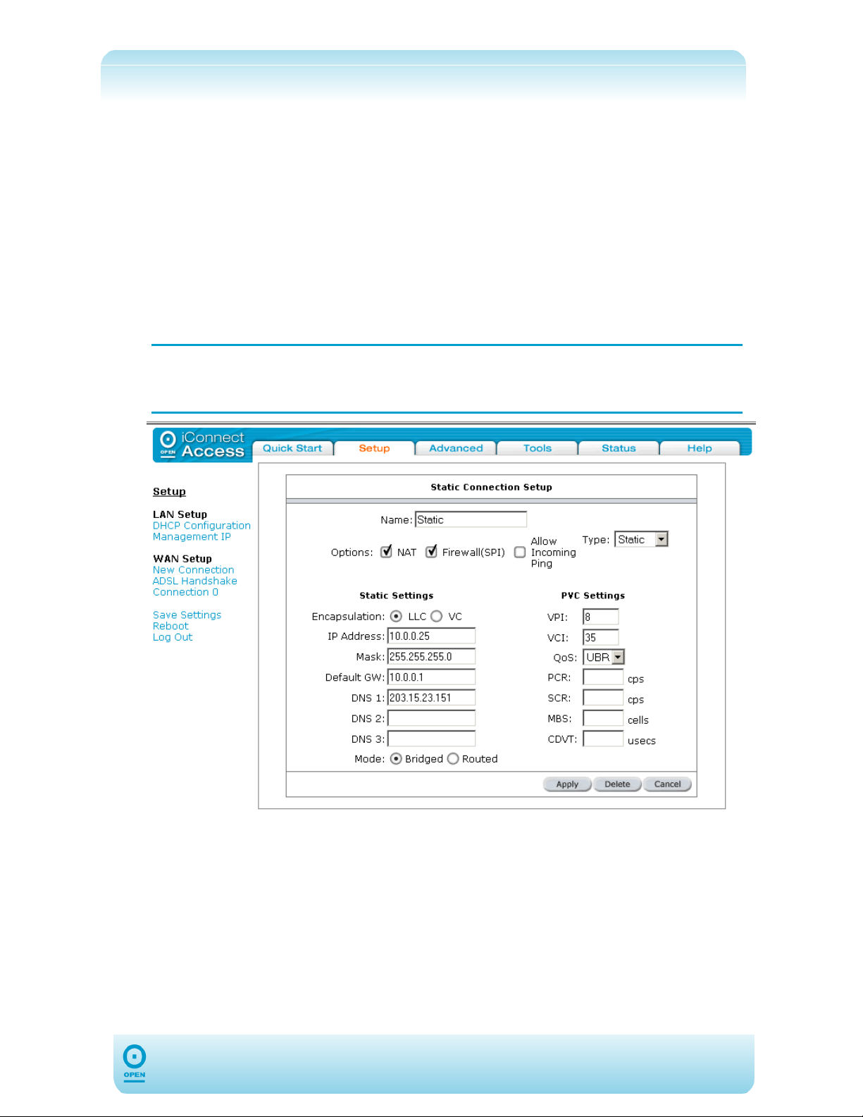
step 2 From the Type drop-down list, select Static. The following appears:
If you need to use the VPI and VCI values in an existing connection, you will
NOTE:
need to open it and edit the setting. It is not possible to have more than one
connection using the same VPI/VCI values.
step 3 Enter a unique name for your static connection in the Name field. The name
must not have spaces and cannot begin with numbers.
step 4 You can also enable Network Address Translation (NAT) and the
Firewall options. If you are unsure, leave these in the default mode.
step 5 Select the encapsulation type (LLC or VC) by highlighting the appropriate radio
button. If you are unsure leave the setting as default.
step 6 Enter the VPI and VCI settings as provided by DSL service provider / ISP.
step 7 In the IP Address field, enter your assigned IP address based on the
information provided by your DSL Provider / ISP.
31
Page 32

step 8 In the Mask field enter the Subnet Mask based on the details provided by your
DSL Provider / ISP.
step 9 In the Default GW field enter the Default Gateway based on the information
provided by your DSL Provider / ISP (if provided).
step 10 In the DNS 1 and 2 fields, enter the Domain Name Services (DNS) values
based on the information provided by your DSL Provider / ISP (if provided).
step 11 In the Mode field, highlight the required connection type radio button as
appropriate. The options are Bridged and Routed.
step 12 Click the Apply button to save the changes temporarily.
step 13 Click Save Settings from the menu list to save the changes permanently.
32
Page 33

The following table lists the Static Connection Setup screen fields and their definitions:
Field Description
Network Address Translation is a feature that enables you to use private IP
NAT
addresses on your PC or your LAN. This is set to Enabled by default for
standard operation.
Firewall (SPI)
Allow Incoming
Ping
Encapsulation
IP Address
Mask
Default Gateway
DNS 1 – DNS 3
Mode
Select to enable firewalling on this connection. This is set to Enabled by
default for standard operation.
Ping is a protocol used mainly for monitoring the connectivity between IP
devices. Enabling this feature allows remote devices to use ping to check
connectivity to your device. You may need to enable this for monitoring
purposes. This is set to Disabled by default for standard operation.
LLC and VC are two different methods of encapsulating multiple sessions. This
is set to LLC by default.
LLC
VC
This is the static IP that will be assigned to the WAN interface of the 624. This
will be provided by your ISP.
A mask used to determine to which the subnet an IP address belongs. This is
the Subnet Mask that will be assigned to the WAN interface of the 624. This will
be provided by your ISP.
The default gateway is a host to which local computers send data that is
destined for a non-local machine. On the 624, configure the default gateway
address here to reach all computers that are not on the same local IP subnet.
DNS service is used to translate a Domain Name into a corresponding IP
address. The DNS server name should be obtained from your ISP.
Routed or Bridged mode can be selected here.
With LLC encapsulation, a link control header is added to the Ethernet
packet that identifies the protocol type (Ethernet). This allows multiple
protocols to be transmitted over the ATM Virtual Circuit.
With VC Multiplexing, no link control header is needed as the ATM
Virtual Circuit is assumed to be carrying a single protocol
VPI
VCI
QoS
The VPI (Virtual Path Identifier) defines the virtual path settings for the ADSL
connection between you and your ISP. The VPI value entered here must be
supported by your ISP.
The VCI (Virtual Channel Identifier) defines the virtual channel
settings for the ADSL connection between you and your ISP. The VCI value
entered here must be supported by your ISP.
QoS defines the 624 capabilities that provide guarantee of performance such as
traffic delivery priority, speed, latency, or latency variation. Delivery of goodquality audio or video streams typically requires QoS capabilities. Three
different quality of service options are available in the 624. These are UBR,
CBR and VBR. The QoS selected here must be supported by your ISP. By
default this is set to UBR.
33
Page 34
DHCP Connection Type Set Up:
Dynamic Host Configuration Protocol (DHCP) allows the 624 to obtain an IP address
automatically from the server. With dynamic addressing, a device may have a different IP
address every time it connects to the network. This is not commonly used in Australia.
Before configuration, please check with your DSL Provider / ISP to ensure that this mode is
supported.
To Configure The 624 For A DHCP Connection:
step 1 From the main screen, click Setup.
step 2 From the WAN Setup menu click New Connection.
The default PPPoE Connection Setup screen is displayed.
If you need to use the VPI and VCI values in an existing connection, you will
NOTE:
need to open it and edit the setting. It is not possible to have more than one
connection using the same VPI/VCI values.
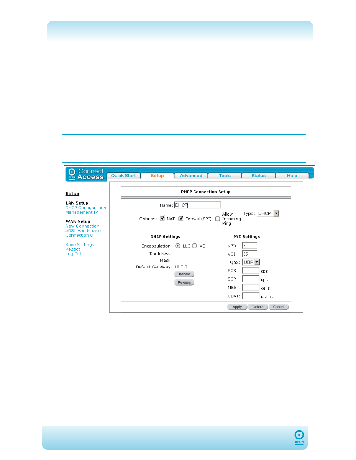
step 3 From the Type drop-down list select DHCP.
step 4 Enter a unique name for the DHCP Connection in the Name field. The name
must not have spaces and cannot begin with numbers.
step 5 In the Options area of the screen, leave the NAT and Firewall checkboxes
as default. (ie, checked.)
step 6 Select the encapsulation type (LLC or VC) by highlighting the appropriate radio
button. If you are unsure leave the setting as default.
step 7 Enter the VPI and VCI settings as provided by your DSL Provider / ISP.
step 8 If your DSL line is connected and your DSL/ISP provider supports DHCP, click
the Renew button to retrieve an IP address, Subnet mask, and Gateway
address.
34
Page 35

You can renew the DHCP address at any time by clicking Renew.
NOTE:
However, in most cases you will never need to use this button as the
process runs automatically.
step 9 Click Apply to save the connection temporarily.
step 10 To make the change permanent click Save Settings from the menu list.
The following table lists the DHCP Connection Setup screen fields and their definitions:
Field Description
Network Address Translation is a feature that enables you to use private
NAT
Firewall (SPI)
Allow Incoming
Ping
IP addresses on your PC or your LAN. This is set to Enabled by default for
standard operation.
Select to enable firewalling on this connection. This is set to Enabled by default
for standard operation.
Ping is a protocol used mainly for monitoring the connectivity between IP
devices. Enabling this feature allows remote devices to use ping to check
connectivity to your device. You may need to enable this for monitoring
purposes. T his is set to Disabled by default for standard operation.
Encapsulation
Renew
Release
VPI
VCI
QoS
LLC and VC are two different methods of encapsulating multiple sessions. This
is set to LLC by default.
LLC
VC
Sometimes it becomes necessary to get a new IP address or update DHCP
options sent by a DHCP server, for example when moving a laptop from one
network to another. Pressing this button will renew the DHCP lease.
Clicking this button will release the current network settings from the 624.
The VPI (Virtual Path Identifier) defines the virtual path settings for the
ADSL connection between you and your ISP. The VPI value entered here must
be supported by your ISP.
The VCI (Virtual Channel Identifier) defines the virtual channel
settings for the ADSL connection between you and your ISP. The VCI value
entered here must be supported by your ISP.
QoS defines 624 capabilities that provide guarantee of performance such as
traffic delivery priority, speed, latency, or latency variation. Delivery of goodquality audio or video streams typically requires QoS capabilities Three different
quality of service options are available in the 624. These are UBR, CBR and
VBR. The QoS selected here must be supported by your ISP. By default this is
set to UBR.
With LLC encapsulation, a link control header is added to the Ethernet
packet that identifies the protocol type (Ethernet). This allows multiple
protocols to be transmitted over the ATM Virtual Circuit.
With VC Multiplexing, no link control header is needed as the ATM
Virtual Circuit is assumed to be carrying a single protocol.
35
Page 36
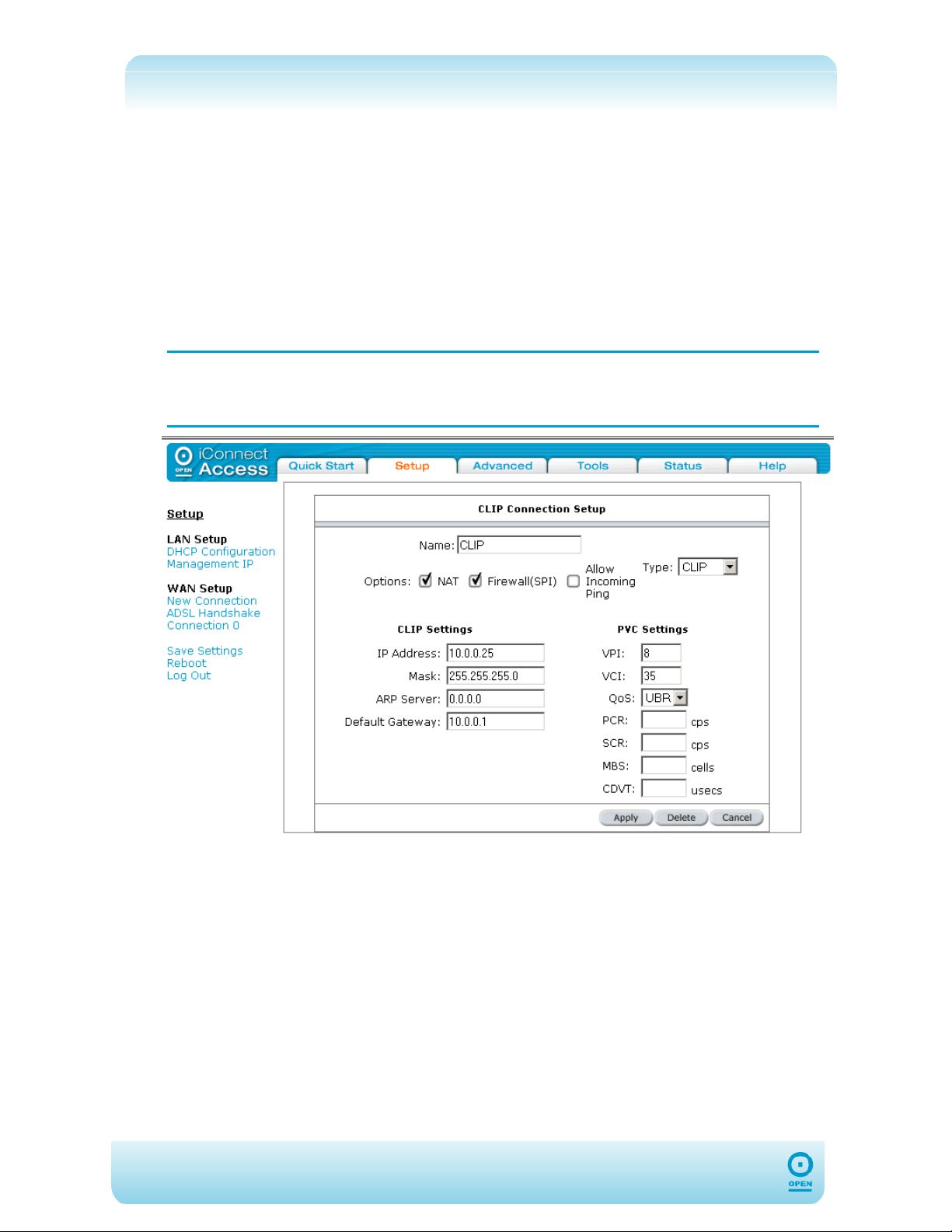
Classical IP Over ATM (CLIP) Connection Set Up
Classical IP over ATM (CLIP), (defined in RFC1577) provides the ability to transmit IP
packets over an ATM network, CLIP support will encapsulate IP in an AAL5 packet data unit
(PDU) frame using RFC1577and it utilizes an ATM aware version of the ARP protocol.
To Configure The 624 For A CLIP Connection:
step 1 From the main screen, click Setup.
step 2 From the WAN Setup menu, click New Connection.
The default PPPoE Connection Setup screen appears.
step 3 From the Type drop-down list select CLIP. The following appears:
If you need to use the VPI and VCI values in an existing connection, you will
NOTE:
need to open it and edit the setting. It is not possible to have more than one
connection using the same VPI/VCI values.
step 4 Enter a unique name for the CLIP connection in the Name field. The name must
not have spaces and cannot begin with numbers.
step 5 Leave the NAT and Firewall options as the default settings. (ie, checked.)
step 6 Enter the VPI and VCI settings as provided by your DSL Provider / ISP.
step 7 From the Quality of Service (QoS) drop-down list, select the QoS required,
or if you are uncertain, leave the default value.
step 8 Enter the CLIP Settings, including IP Address, Mask and Default
Gateway as provided by your DSL Provider / ISP.
step 9 Leave the ARP Server address as the default, unless advised by your DSL
Provider / ISP.
step 10 Click Apply to save the changes temporarily.
36
Page 37
step 11 To make the changes permanent click Save Settings from the menu list.
Modify An Existing Connection
To Modify An Existing Connection:
From the main screen, click Setup, then click the connection you wish to modify.
The connections are listed as Connection 0 through Connection 7.
Edit as applicable and click Apply, or if you are deleting the entry, click Delete.
To make the changes permanent, click Save Settings from the menu list.
The following table lists the Connection Setup buttons and their definitions:
Field Description
Apply
Delete
Cancel
Applies the changes made to the connection.
Deletes the connection.
Cancels the changes made to the connection before applying.
Modem Set Up
To Configure The DSL Modem Type:
step 1 From the main screen, click Setup.
step 2 Under the WAN Setup menu, select ADSL Handshake. The screen below
appears. Leave the default setting if you are unsure of this value.
37
Page 38
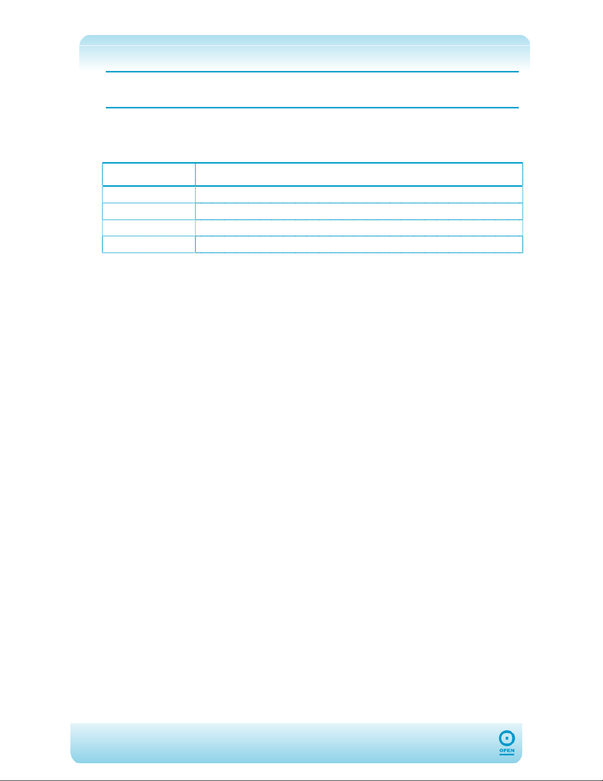
NOTE:
The 624 is pre-configured to detect the ADSL modulation standard
automatically. In most cases, this screen should not be modified.
step 3 Click Apply to save the changes temporarily.
step 4 To make the changes permanent click Save Settings from the menu list.
The following table lists the ADSL Handshake screen fields and their definitions:
Field Description
T1413
GDMT
GLITE
MMODE
ANSI T1.413-1998
G.DMT (G.992.1)
G.lite (G.992.2)
Multi-Mode (the modulation is automatically detected)
Enable Incoming ICMP Ping
Enabling the Incoming Internet Control Message Protocol (ICMP) Ping will allow Echo
requests to come into the gateway. The gateway will respond with an ICMP Echo response
message. The option allows the DSL provider or ISP to determine the following:
The status of the network;
Tracking and isolating hardware and software problems;
Testing, measuring, and managing networks.
38
Page 39
Advanced Tab
The 624 supports a host of advanced networking and routing features including security, port
configuration, and plug and play capability.
UPnP
Universal Plug and Play is a networking architecture that provides compatibility among
networking equipment, software and peripherals such as games consoles, digital cameras,
and other systems that connect by TCP/IP. It can be supported on any operating system,
and boasts device-driver independence and zero-configuration networking.
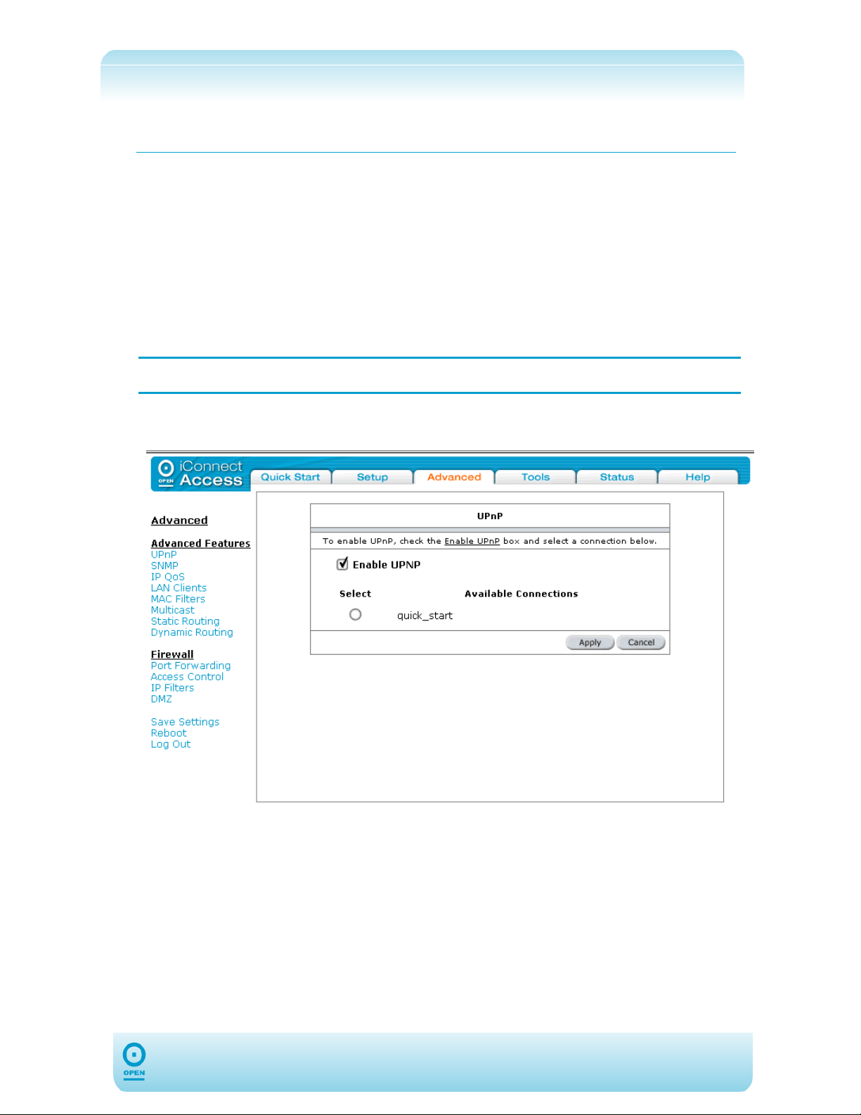
To Enable UPnP:
NOTE: Before enabling UPnP, ensure that you have a WAN connection configured.
step 1 From the main menu, click Advanced.
step 2 Under the Advanced Features menu, click UPnP. The following appears:
39
Page 40
step 3 Select the required Available Connection by highlighting the appropriate
Select radio button.
step 4 Check the Enable UPnP checkbox.
step 5 Click Apply to temporarily save the connection.
step 6 Click Save Settings from the menu to make the change permanent.
The following table lists the UPnP screen fields and their definitions:
Field Description
Universal Plug and Play (UPnP) is a standard that uses Internet and Web
protocols to enable the 624 to be plugged into a network and automatically know
about each other. With UPnP enabled, when a user plugs the 624 into the
Enable UPNP
network, the device will configure itself, acquire a TCP/IP address, and use a
discovery protocol based on the Internet's Hypertext Transfer Protocol (HTTP) to
announce its presence on the network to other devices. This is set to
Disabled by default in the 624.
NOTE: UPnP can only be enabled on a saved Configuration File.
40
Page 41
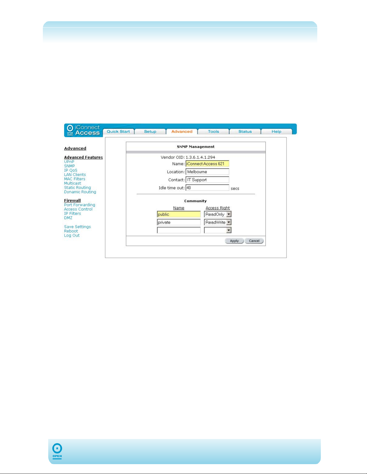
SNMP
SNMP stands for Simple Network Management Protocol. It is used to monitor the state of
the network. For example, SNMP can be used to monitor the amount of traffic passing
through the network.
To Configure SNMP Details:
step 1 From the main menu, click Advanced.
step 2 From the Advanced Features menu, click SNMP. The following appears:
step 3 In the SNMP Management screen, enter a name for the device in the Name field.
step 4 Enter the vendor’s location in the Location field.
step 5 Enter a contact for the vendor in the Contact field.
step 6 Enter a time limit (in seconds) for the vendor in the Idle time out field.
step 7 Enter a community name in the Name field in the Community area of the screen,
for read-only access. The default is Public.
step 7 Click Apply to save the changes temporarily.
step 8 Click Save Settings to make the changes permanent.
41
Page 42
The following table lists the SNMP Management screen fields and their definitions:
Field Description
SNMP Management
(Name,
Location,
Contact)
Community Name
and Access
Rights
Enter details specific for this device in the Name, Location and Contact fields.
The SNMP Read-Only Community string is like a User-ID or Password that
allows access to the router’s statistics.
SNMP Read-Write Community String allows a remote device to read information
from a device, and to modify settings on that device. If using SNMP Read-Write
do not leave this password at the default.
42
Page 43
IP QoS
Before attempting to configure IP QoS, you will need a good understanding of the TCP/IP
protocol and ports.
The IP Quality Of Service (QoS) queues data streams to ensure that basic connectivity is
maintained when running multiple services over one connection. For example, if you are
using a peer-to-peer file-sharing program whilst simultaneously performing normal web
browsing, you can configure QoS to limit the resources dedicated to the peer-to-peer session
to ensure web browser connectivity. IP QoS is often critical to maintain VoIP session quality.
IP QoS services in the 624 are applicable to the output device (LAN side). This means that
the IP QoS is associated with any transmitted traffic from the 624. Each output device has
three priority queues associated with transmit data. The High priority queue has strict priority
over medium and low priority queues. The Medium and Low priority queues are serviced on
a round robin priority basis according to the configured weights (WRR), after the High priority
queue has been completely serviced.
If IP QoS is enabled and no rules are defined, a default rule is added which is
NOTE:
hidden. The default rule places all traffic to be transmitted in the Low priority
queue.
To Configure IP QoS:
step 1 From the main screen, click Advanced.
step 2 From the Advanced screen, click IP QoS under the Advanced Features
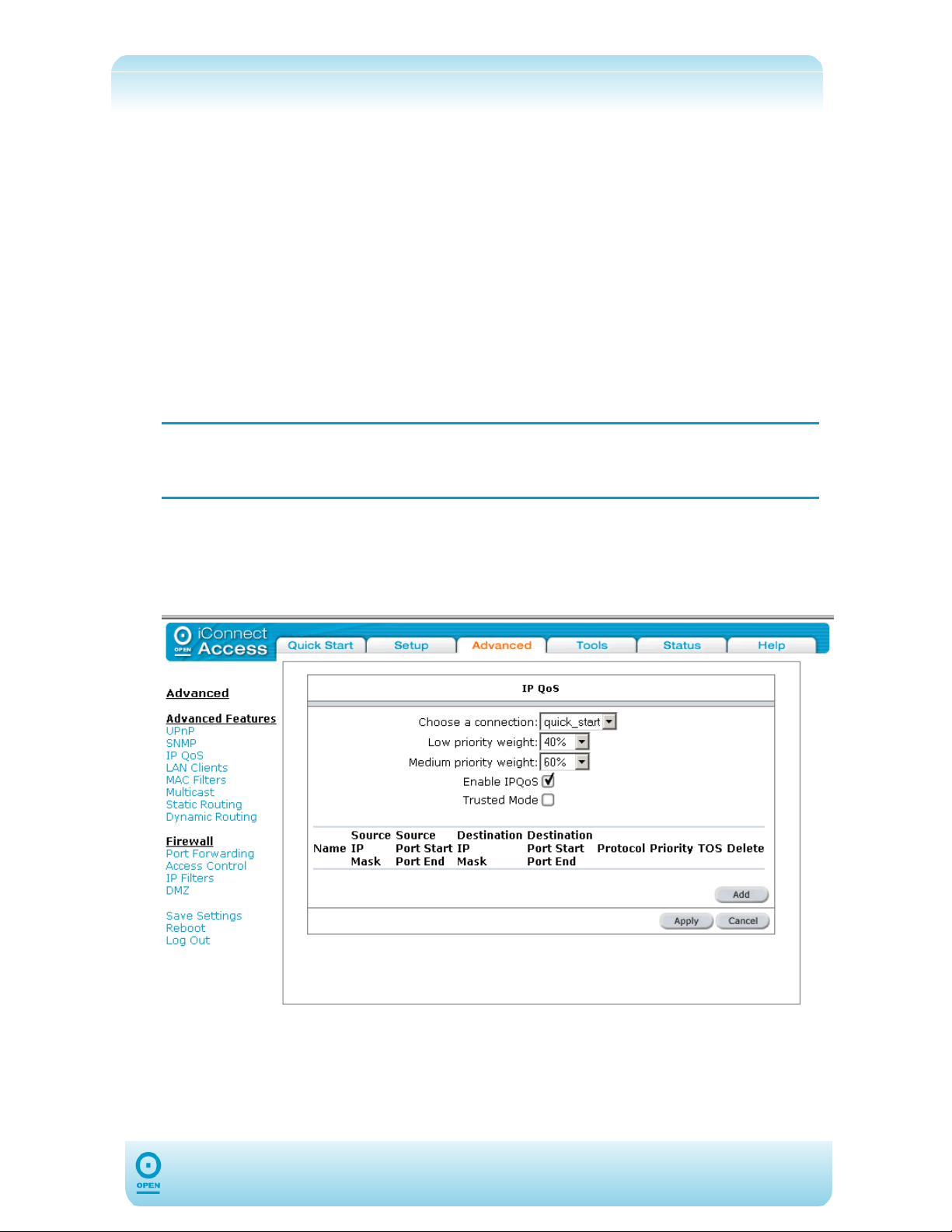
menu. The following screen appears:
step 3 Select a WAN connection to enable IP QoS for the modem’s upstream traffic, or
choose a LAN connection (Ethernet Bridged) for the downstream traffic, from
the Choose a connection drop-down list.
step 4 Select a percentage from the Low priority weight drop-down list.
43
Page 44
step 5 Select a percentage from the Medium priority weight drop-down list.
step 6 If you wish to enable IPQoS, check the Enable IPQoS checkbox.
step 7 If you wish to enable trusted mode, check the Trusted Mode checkbox.
step 8 Click Apply to save the changes temporarily.
step 9 Click Save Settings from the menu list to make the changes permanent.
The following table lists the IP QoS screen fields and their definitions:
Field Description
Choose a
Connection
Low Priority
Weight / Medium
Priority Weight
Enable IP QoS
Trusted Mode
This lists the connection names that are configured on the 624. Select a WAN
or LAN connection here.
These two fields allow you to select the weights of the Medium and Low Priority
queues in increments of 10 percent, so that the sum of the weights is 100
percent.
Check /uncheck this checkbox to enable / disable IP QoS for the selected
connection.
The 624 has two primary modes of operation: Trusted and Untrusted.
Trusted: In Trusted mode, all the rules will be applied first, regardless of the
Type Of Service (TOS) bit setting. (After the rules have been exhausted, the
existing TOS bit settings will be honoured.)
Untrusted: Untrusted Mode matches first against all rules, as in Trusted Mode.
If there is no match, then a default rule will be used. The queuing priority of the
default rule is Low.
44
Page 45
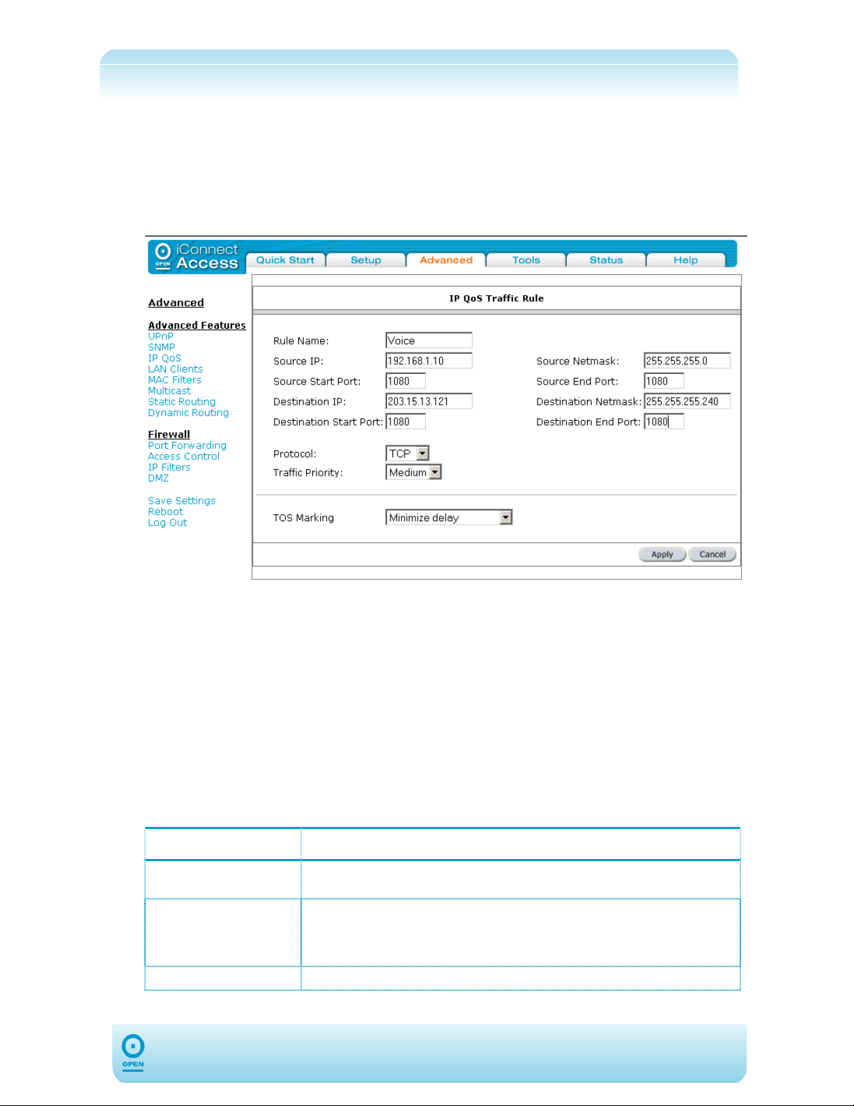
To Define IP QoS Traffic Rules:
The IP QoS page appears when you click the Add button in the QoS Setup screen. When
setting rules, each rule is a matching criterion that identifies the application traffic to be
transmitted by the 624 using one of the three priority queues – High, Medium or Low.
step 1 From the IP QoS screen, click Add to define the IP QoS traffic rules. The
following screen appears:
step 2 Enter a rule name in the Rule Name field.
step 3 Identify the traffic by source and destination address and ports.
step 4 Select the protocol from the Protocol drop-down list.
step 5 Select the priority queue in which the identified traffic will be placed, from the
Traffic Priority drop-down list.
step 6 If you wish to set the TOS bit, select it from the TOS Marking drop-down list.
step 7 Click Apply to save the changes temporarily.
step 8 The rule will be added to the rule list on the IP QoS screen. Click Save
Settings from the menu list to make the changes permanent.
The following table lists the IP QoS Traffic Rule screen fields and their definitions:
Field Description
Rule Name
Identify Traffic
Traffic Priority
This lists the connection names that are configured in the 621. Select a
connection here.
The Application traffic can be identified by Source/Destination IP Address,
Netmask, Source / Destination Port and Protocol, Wildcard (*) entries are
allowed for IP Address / Netmask and Port Range fields. The options for
Protocol are: ANY, ICMP, TCP and UDP.
This field corresponds to the Priority Queue (High / Medium / Low) for
45
Page 46

TOS Marking
this traffic.
The additional TOS marking field allows you to assign a Type Of Service
(TOS) value to this traffic. The values for the TOS marking are: No
Change, Normal Service, Minimize Monetary Cost, Maximize
Reliability, Maximize Throughput and Minimize Delay.
46
Page 47
LAN Clients
If DHCP is used, all current DHCP clients are automatically registered in the LAN Client
database. However, if a Static IP Address is used on a LAN device and you need this to be
visible via the WAN, you must add its IP address to the LAN Clients list. Once the IP
address has been added you will be able to apply Port Forwarding, IP Filtering and QoS
rules to it.
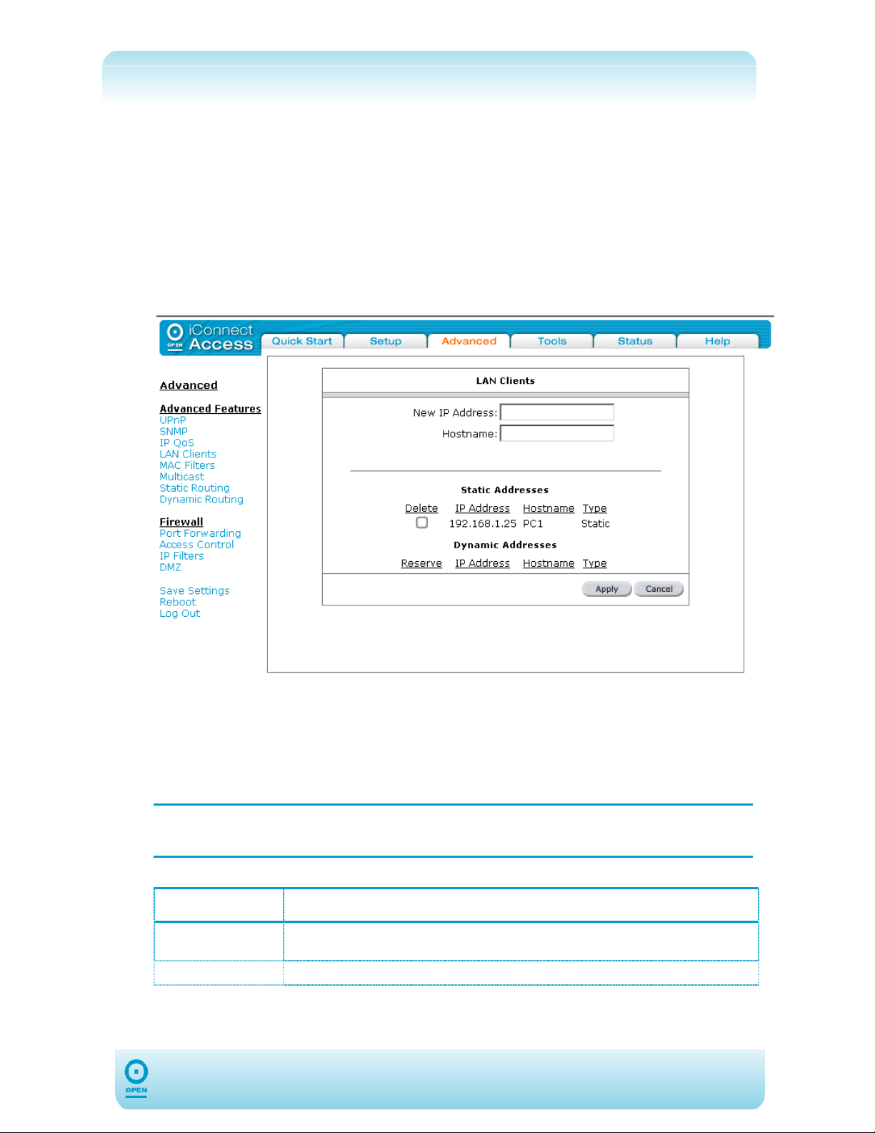
To Add A LAN Client:
step 1 From the main screen, click Advanced, then from the Advanced Features
menu, click LAN Clients. The following screen appears:
step 2 To add the LAN Client Address, enter the LAN IP Address in the New IP
Address field.
step 3 Enter the LAN’s hostname in the Hostname field if required.
step 4 Click Apply to save the changes temporarily.
step 5 Click Save Settings from the menu list to save the changes permanently.
NOTE:
Once the IP Address has been added you are now able to apply Port Forwarding
and Access Control rules to it.
The following table lists the LAN Clients screen fields and their definitions:
Field Description
New IP Address
Hostname
IP address of the server/host that you want to use for port forwarding or access
control must be defined here.
An optional hostname can be assigned to the above address.
47
Page 48
MAC Address Filters
The MAC filtering mechanism enables users to define rules which allow/deny frames through
the 624, based on source and destination MAC address and/or frame type. The user should
note that the MAC filter will only examine frames from interfaces that are part of the bridge
itself. Twenty filter rules are supported with MAC filtering.
The User Interface for MAC Filter allows the following functionality:
Adding/Editing/Deleting filter rules,
Enabling filter rules.
To Enable MAC Address Filters:
The Enable MAC Filters button allows the user to enable or disable MAC filtering. It can
be checked / unchecked during any editing operation. It can also be set/unset independently
by just pressing the Apply button.
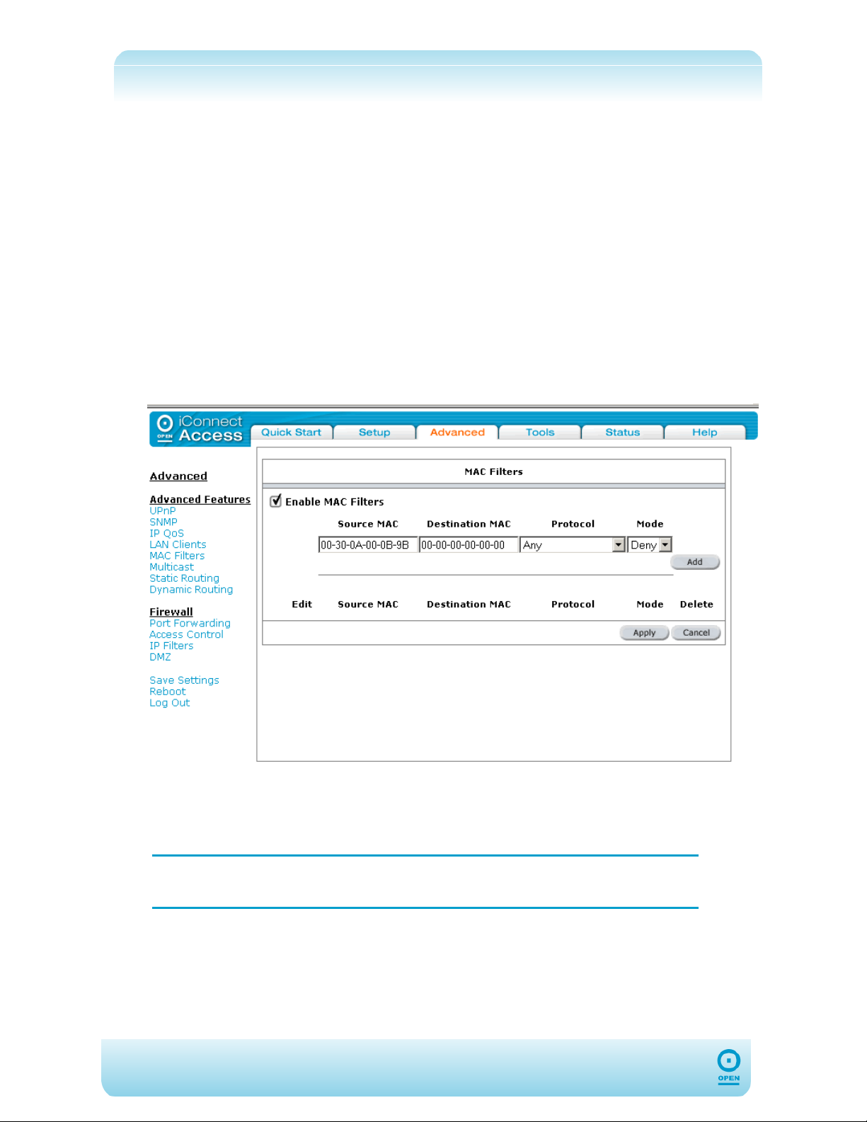
step 1 From the main screen, click Advanced and under the Advanced Features
menu, select MAC Filters. The following screen appears:
step 2 Check the Enable MAC Filters checkbox, and click Apply.
step 3 Enter the source MAC address in the Source MAC field.
step 4 Enter the destination MAC address in the Destination MAC field.
NOTE:
Entering 0s or blanks in the Source or Destination fields enters a
null value.
step 5 Select the protocol to be used from the Protocol drop-down list.
step 6 Select the mode with desired filtering type from the Mode drop-down list. The
options are Allow or Deny.
step 7 Click Add.
48
Page 49

step 8 Click Apply to save the change temporarily.
step 9 Click Save Settings from the menu list.
NOTE: A maximum of 20 MAC Filter Rules can be defined and saved.
To Edit An Existing Filter Rule:
From the MAC Filters screen, highlight the Edit radio button for the rule to be
edited, from the list of existing filter rules.
The rule appears in the Enable MAC Filters area of the screen.
Make the required change / s to the MAC Address, Protocol and Mode types,
and click Apply, then Save Settings from the menu list.
To Delete Filter Rule(s):
Check the Delete checkbox beside the filter rule / s to be deleted.
Multiple deletions are possible by using the <Shift> key and clicking the
NOTE:
Delete checkboxes. The Select All checkbox can be used to delete all
filter rules quickly.
Click Apply.
Click Save Settings from the menu list to make the changes permanent.
Hidden MAC Filter Rules:
The MAC filter table contains 3 hidden rules, which are entered automatically by the system
to ensure you do not "lock" yourself out of the system. These include:
Any ARP frames are permitted to pass through the system.
All IPv4 frames with the destination MAC address of the bridge are permitted to
pass through.
All IPv4 frames with the source MAC address of the bridge are permitted to pass
through.
NOTE:
To locate the MAC Address of a Windows-based machine, type
ipconfig/all at a DOS prompt.
49
Page 50
Multicast
Multicasting is a form of limited broadcast. UDP is used to send datagrams to all hosts that
belong to what is called a "host group." A host group is a set of one or more hosts identified
by the same destination IP address. The following statements apply to host groups.
Anyone can join or leave a host group at will;
There are no restrictions on a host's location;
There are no restrictions on the number of members that may belong to a host
group;
A host may belong to multiple host groups;
Non-group members may send UDP datagrams to the host group.
Multicasting is useful when data needs to be sent to more than one other device. For
instance, if one device is responsible for acquiring data that many other devices need, then
multicasting is a natural fit. Note that using multicasting as opposed to sending the same
data to individual devices uses less network bandwidth.
To Enable Multicasting:
step 1 From the main screen, click the Advanced tab.
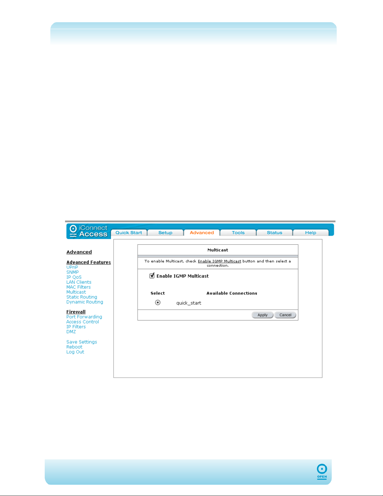
step 2 From the Advanced Features of the Advanced menu, click Multicast. The
following screen appears:
step 3 Check and / or highlight the checkbox and radio button as required, then click
Apply to save the connection temporarily.
step 4 Click Save Settings from the menu list to make the changes permanent.
50
Page 51
The following table lists the Multicast screen fields and their definitions:
Field Description
Enable IGMP
Multicast
Available
Connection
IP packets are transmitted in one of either two ways;
Unicast (1 sender to 1 recipient) or
Broadcast (1 sender to everybody on the network).
Multicast delivers IP packets to just a group of hosts on the network. IGMP
(Internet Group Multicast Protocol) is a session-layer (layer-3)
protocol used to establish membership in a Multicast group. Checking this will
enable the 624 to receive multicast traffic. Refer to RFC 1112 and RFC 2236 for
information on IGMP versions 1 and 2 respectively.
Select the connection type here.
51
Page 52
Static Routing
If the 624 is connected to more than one network, you may need to set up a static route
between them. A static route is a pre-defined pathway down which network information must
travel to reach a specific host or network. You can use static routing to allow different IP
domain users to access the Internet through the 624.
To Enable Static Routing:
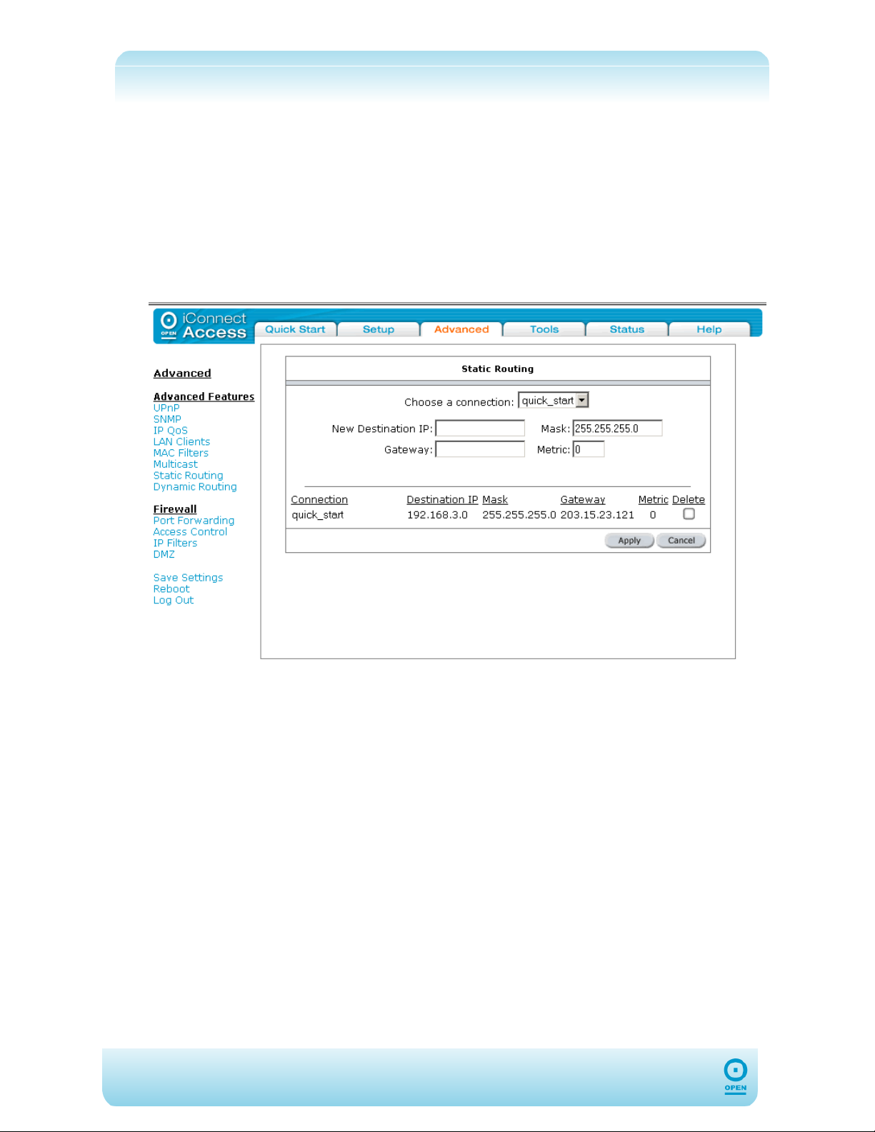
step 1 From the main screen, click Advanced and under Advanced Features,
select Static Routing. The following screen appears:
step 2 From the Choose a connection drop-down list, select a connection type.
step 3 Enter the new destination IP for the remote LAN network or host to which you
wish to assign a static route in the New Destination IP field.
step 4 Enter a subnet mask in the Mask field.
step 5 Enter the IP address of the near device to connection with the remote network
or host in the Gateway field.
step 6 Enter a metric in the Metric field.
step 7 Click Apply to save this connection temporarily.
step 8 To make the change permanent, click Save Settings from the menu list.
52
Page 53
The following table lists the Static Routing screen fields and their definitions:
Field Description
Choose a
Connection
New Destination
IP
Mask
Gateway
Metric
Choose the connection profile from the drop-down list.
This is the destination network or Host IP to which packets will be sent.
A mask used to determine the subnet to which an IP address belongs. This is
the mask that determines the destination network.
This is the IP address of the next hop router in the path of the destination
network. When a packet is ready to be sent to a destination, the 624 sends it on
to the Gateway. The gateway examines the destination address in the header
and passes the packet along to another router, chosen by a route-finding
algorithm. A packet may go through 30 or more routers in its travels from one
host computer to another. Because routes are dynamically updated, it is
possible for different packets from a single session to take different routes to the
destination.
Metric (hop count) is used to measure the distance between the source and a
destination network. Each hop in a path from source to destination is assigned a
hop count value, which is typically 1.
53
Page 54
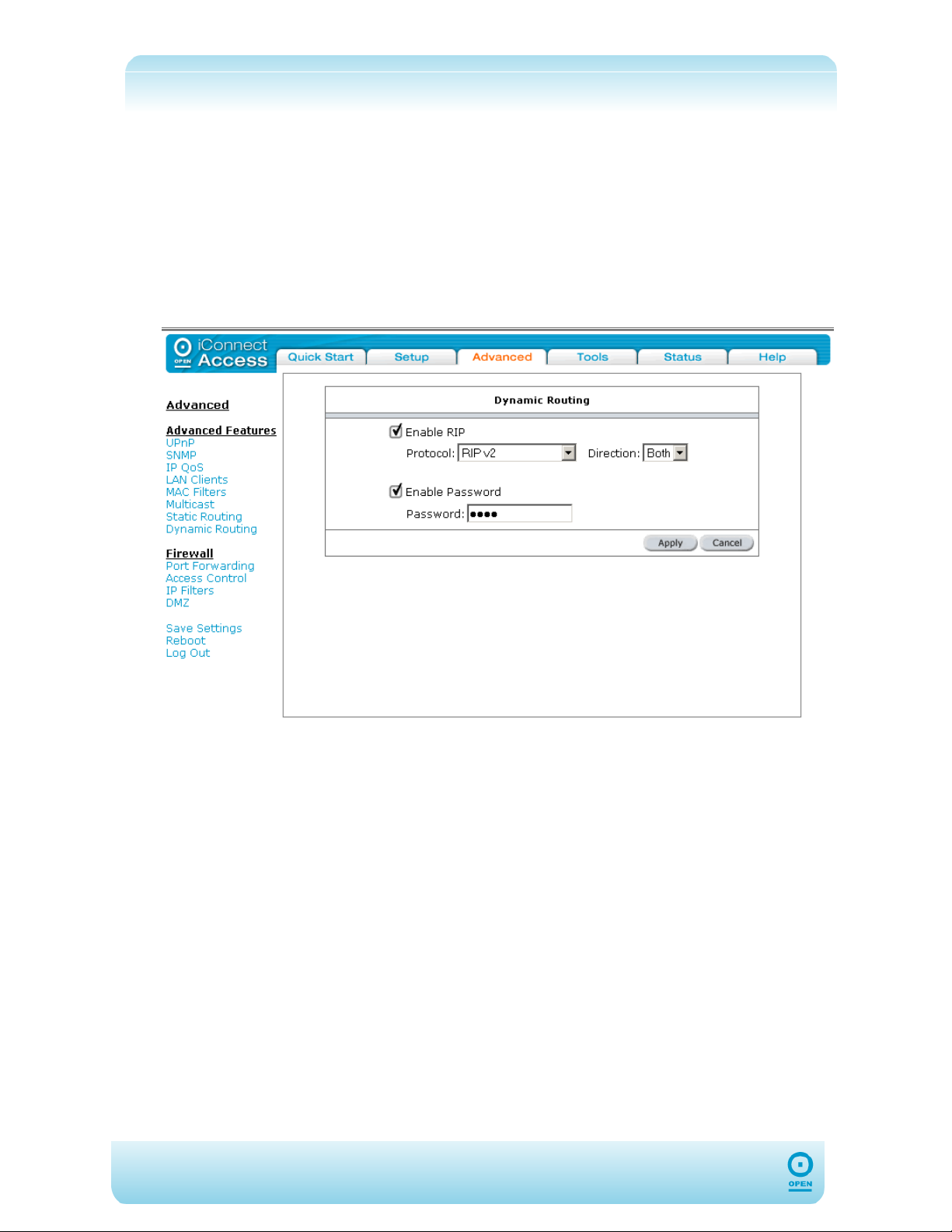
Dynamic Routing
Using Routing Information Protocol (RIP), dynamic routing allows the 624 to adjust to
physical changes in the network automatically. It determines the route through which the
packets travel based on the fewest number of hops between the source and destination. RIP
protocol regularly broadcasts routing information to other Routers on the network.
To Enable Dynamic Routing:
step 1 Click Advanced and under Advanced Features, select Dynamic Routing.
The following screen appears:
step 2 Check the Enable RIP checkbox.
step 3 From the Protocol drop-down list, select the RIP version as appropriate.
step 4 Select the direction from the Direction drop-down list.
step 5 Check / Uncheck the Enable Password checkbox as appropriate.
step 6 If you have checked the Enable Password checkbox, enter a password in the
Password field.
step 7 Click Apply to save the changes temporarily.
step 8 Click Save Settings from the menu list to make the changes permanent.
54
Page 55
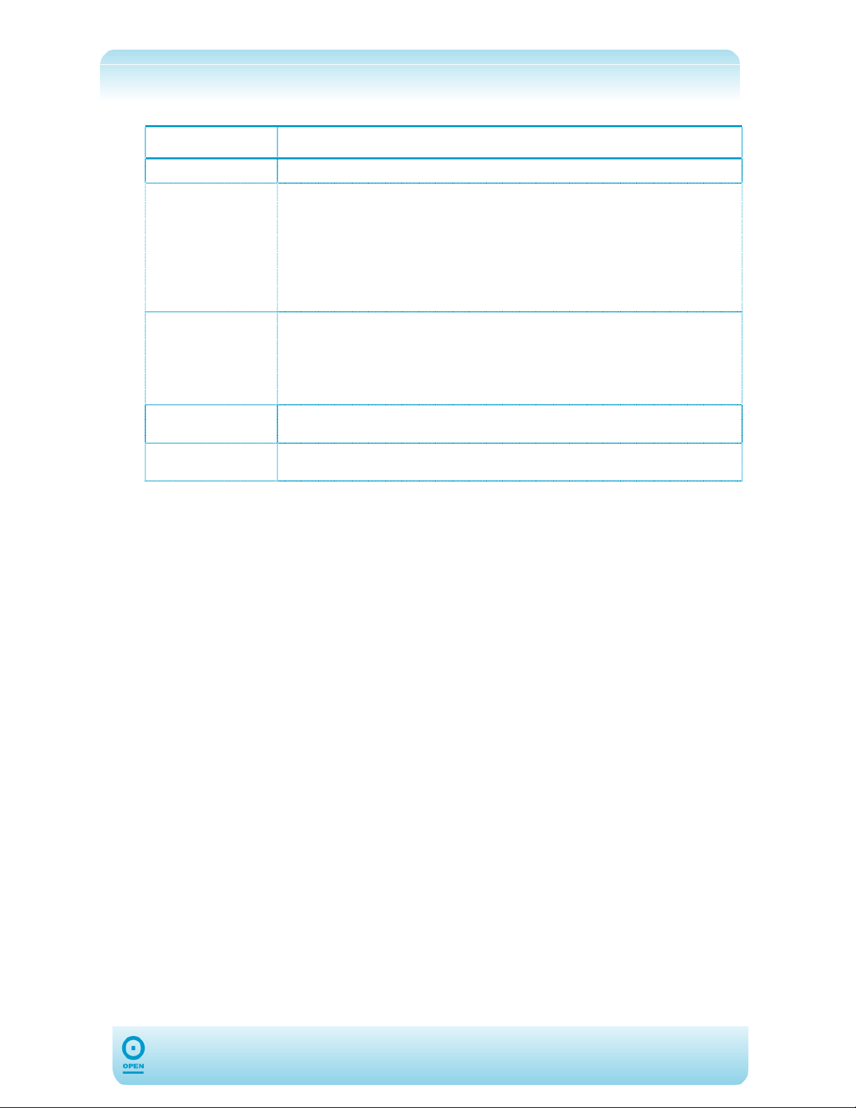
The following table lists the Dynamic Routing screen fields and their definitions:
Field Description
Enable RIP
Protocol
Direction
Enable Password
Password
This enables RIP routing on the 624 router.
There are two versions of RIP. RIP version 1 (v1) is defined in RFC 1058. RIP
version 2 (v2) is defined in RFC 1723. Select between RIPv1, RIPv2 and RIPv1
compatible.
The protocol is dependent upon the entire network. Most networks support RIP
v1. If RIP v1 is selected, routing data will be sent in RIP v1 format. If RIP V2 is
selected, routing data will be sent in RIP v2 format using subnet broadcasting. If
RIP V1-Compatible is selected, routing data will be sent in RIP v2 format using
multicasting.
The direction determines the means through which RIP routes will be updated.
Selecting In means that the 624 will only incorporate received RIP information.
Selecting Out means that the 624 will only send out RIP information.
Selecting Both means that the 624 will incorporate received RIP information
and send out updated RIP information.
Simple password authentication for RIPv2 was defined in RFC 1723. If you
intend to use password authentication you must enable your password here.
Type the RIPv2 authentication password here. Ensure that all routers are
configured with this password for RIPv2 to work.
55
Page 56

Firewall
In the presence of the firewall, anonymous Internet traffic is blocked. Using advanced
security features, you can redirect this traffic to a dedicated computer on your local network
Demilitarised Zone (DMZ) or open access from the Internet to the 624 management ports
(web, Telnet). The 624’s firewall and NAT services (port forwarding, access control) can be
disabled for all interfaces by unchecking the Enable Firewall and NAT Service
checkboxes.
Port Forwarding
Using the Port Forwarding page, you can provide local services (for example web hosting) for
people on the Internet, or play Internet games. When users send this type of request to your
network via the Internet, the 624 will forward those requests to the appropriate computer.
Port Forwarding can be used with DHCP-assigned addresses but remember that a DHCP
address is dynamic (not static). For example, if you were configuring a Netmeeting server,
you would want to assign this server a static IP address so that the IP address is not
reassigned. Also remember that if an Internet user is trying to access an Internet application,
they must use the WAN IP address. Port forwarding will translate the WAN IP address into a
LAN IP address.
Configuring Port Forwarding is a two-part process. Firstly you must ensure that you have a
LAN IP Address configured, and once you have completed this, you can then configure Port
Forwarding.
56
Page 57
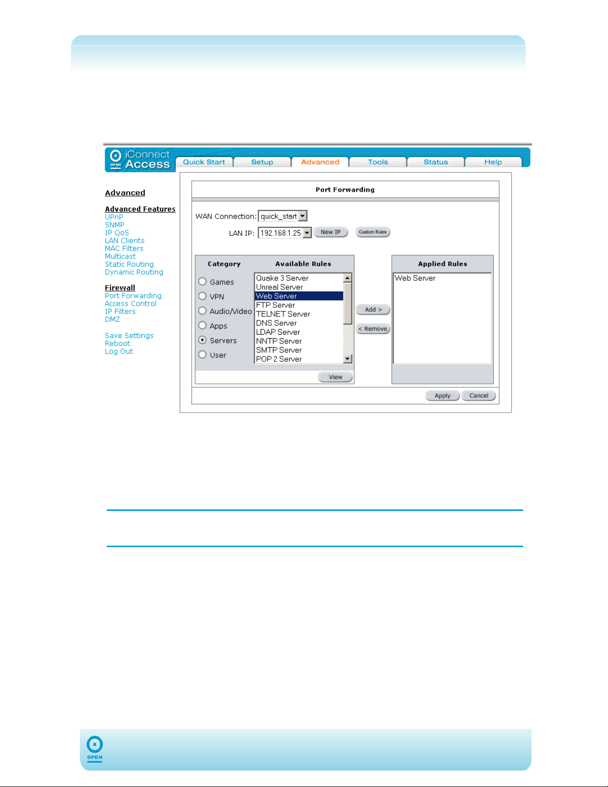
To Configure Port Forwarding:
step 1 From the main screen, click Advanced.
step 2 From the Firewall menu, select Port Forwarding. The following screen
appears:
step 3 From the WAN Connection drop-down list, select the connection type for
which you wish to add the firewall rule.
step 4 From the LAN IP drop-down list, select the IP address for which you wish to
apply the rule. If you wish to add a new LAN IP address, highlight the user
category and click New IP button, and follow the instructions in To Add A LAN
Client:.
NOTE:
It is recommended that Static IP Addresses rather than DHCP IP Addresses
be used for Port Forwarding.
step 5 In the Category area of the screen, highlight the appropriate category radio
button. The Available Rules area displays common Internet services within
the selected category. Rules for each service can be viewed by clicking the
View button.
step 6 To add a rule for this connection, highlight the service / application from the
Available Rules window, then click Add.
The rule then appears in the Applied Rules area of the screen.
step 7 Click Apply to save the rule temporarily.
step 8 Click Save Settings from the menu list to save the rule permanently.
57
Page 58
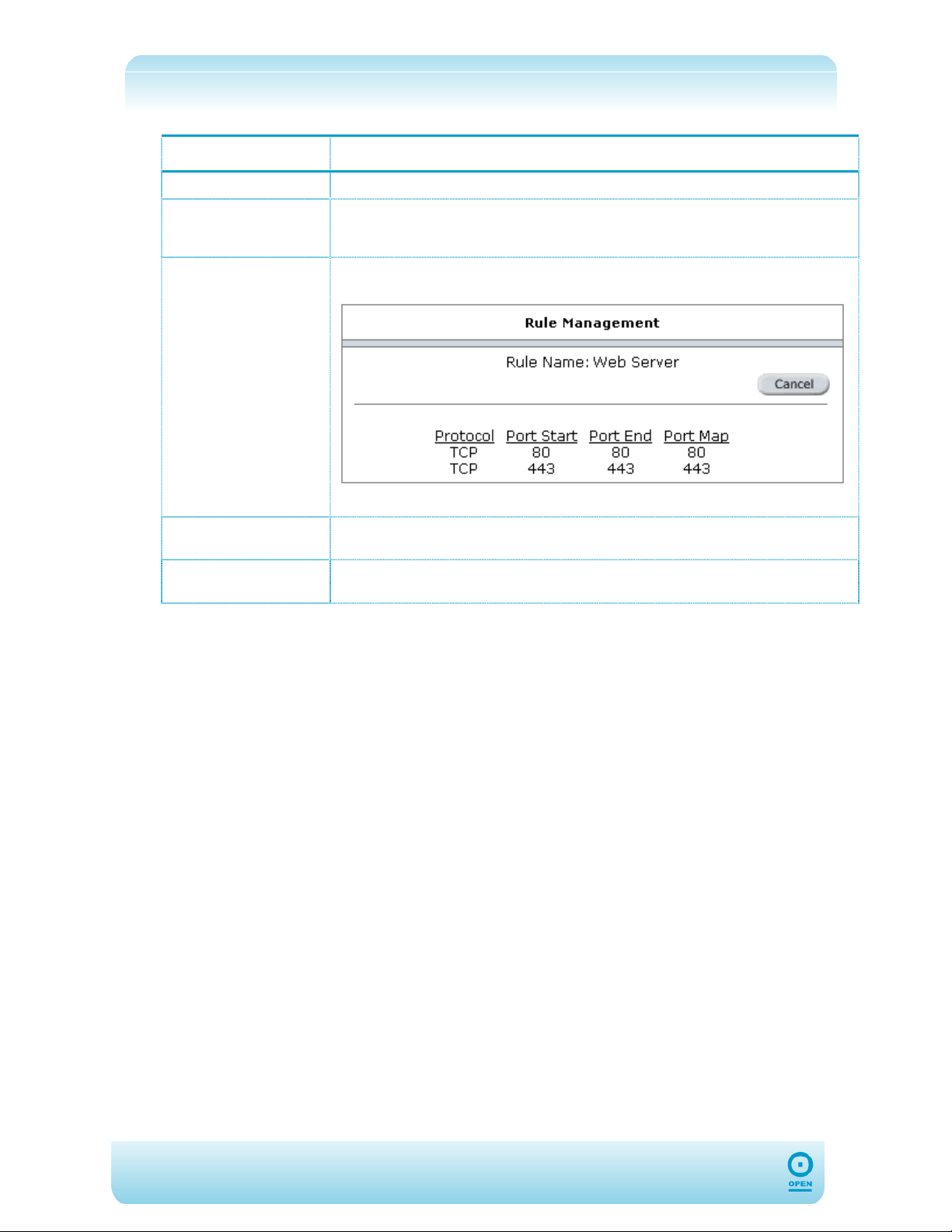
The following table lists the Port Forward screen fields and their definitions:
Field Description
WAN Connection
LAN IP
Category/Available
Rules
Applied Rules
Custom Rules
This is the list of connections defined in the WAN Setup area of the interface.
This is the server IP address to which the selected Ports are forwarded. It is
recommended that you use a static IP address for Server. You will need to define
this in the LAN Clients screen. See To Add A LAN Client:
A number of pre-defined categories and rules are available here. E.g.: Web
servers specifies the following port forwarding profile:
To view the details of a pre-defined rule, click View.
This specifies the applied Port Forwarding rule for the selected WAN Connection
and the LAN IP.
You can specify custom Port Forwarding rules by clicking the Custom Rule
button.
58
Page 59
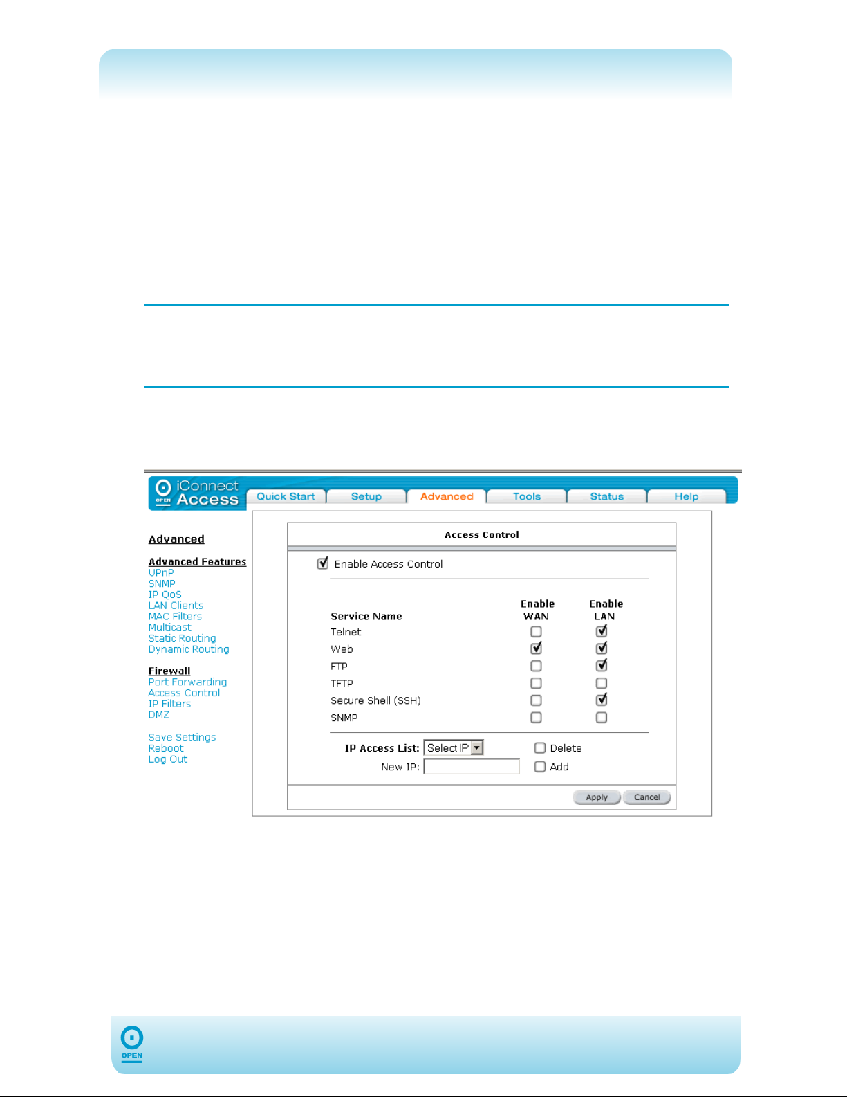
Access Control
The 624’s Access Control management feature opens access from the Internet (WAN) or
(LAN) to the router’s management ports (Web, Telnet, SSH, FTP, TFTP, SNMP). Note that
there are security risks associated with this action, and for this reason, remote management
is restricted to computers on the network that are specified in the IP Access Control List.
(This holds up to 16 IP Addresses.)
The Access Control List (ACL) provides a global enable / disable. If the ACL is disabled, the
default behaviour (ie, Deny for WAN, and Accept for LAN, is enabled for all IP addresses) is
enforced. If no IP Addresses are specified in the ACL, the ACL will act as if it is disabled until
the first IP Address is added.
You must ensure that you add your own IP Address to the IP Access List,
NOTE:
To Enable Access Control:
step 1 From the main screen, click Advanced, then click Access Control from the
otherwise you could lock yourself out of the router. Should this occur and the
setting is saved, you will need to perform a factory default reset, using the
reset button.
Firewall menu.
step2 Check the Enable Access Control checkbox. The following warning
message will appear. Click OK to continue.
59
Page 60
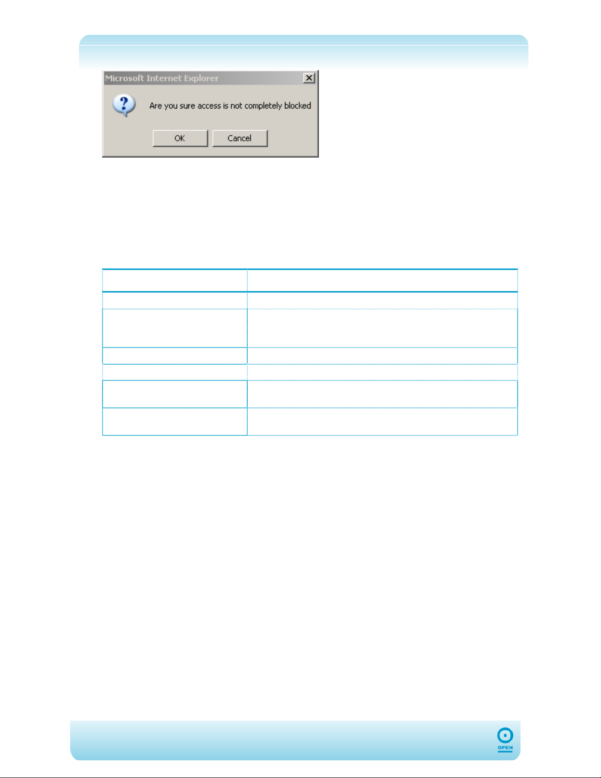
step 3 Select the services you wish to enable on the LAN and WAN sides.
step 4 Enter the management host in the New IP field.
step 5 Check the Add checkbox.
step 6 Click Apply to save the changes temporarily.
step 7 Click Save Settings from the menu list to make the change permanent.
The following table lists the Access Control screen fields and their definitions:
Field Description
Enable Access Control
Service Name (WAN / LAN)
IP Access List
New IP Address
Add
Delete
Global Enable / Disable that enables or disables the ACL.
Services that can be opened on the LAN and WAN sides of the
624. The options are: Telnet, Web, FTP, TFTP, Secure
Shell (SSH), SNMP. Select as many as required.
List of allowed IP Addresses.
Specify the new management host IP Address.
Once you have specified the new management host IP Address,
check the Add checkbox to add it.
Highlight the existing host IP Address and check the Delete
checkbox.
60
Page 61
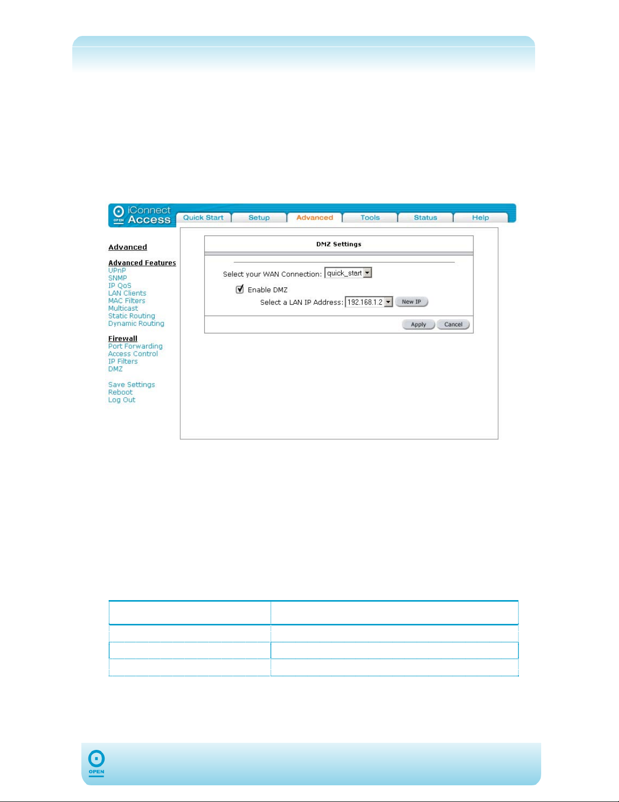
DMZ Configuration
Setting a computer (on your local network) as a De-Militarised Zone (DMZ) forwards any
network traffic that is not redirected to another computer via the port-forwarding feature to the
computer's IP address. This opens access to the DMZ computer from the Internet.
To Configure A DMZ:
step 1 From the main screen, click Advanced, then click DMZ from the Firewall
menu. The following appears:
step 2 From the Select your WAN Connection drop-down list, select the
connection type for which you wish to add the DMZ.
step 3 Check the Enable DMZ checkbox.
step 4 Select the DMZ Host IP Address from the Select a LAN IP Address drop-
down list. If your IP Address is not listed, click New IP, and follow instructions
in To Add A LAN Client:.
step 5 Click Apply to save the changes temporarily.
step 6 Click Save Settings from the menu list to make the changes permanent.
The following table lists the DMZ Settings screen fields and their definitions:
Field Description
Select your WAN Connection
Enable DMZ
Select a LAN IP Address
List of connections defined in the WAN Setup.
Enables / Disables DMZ feature.
Host computer to act as the DMZ.
61
Page 62
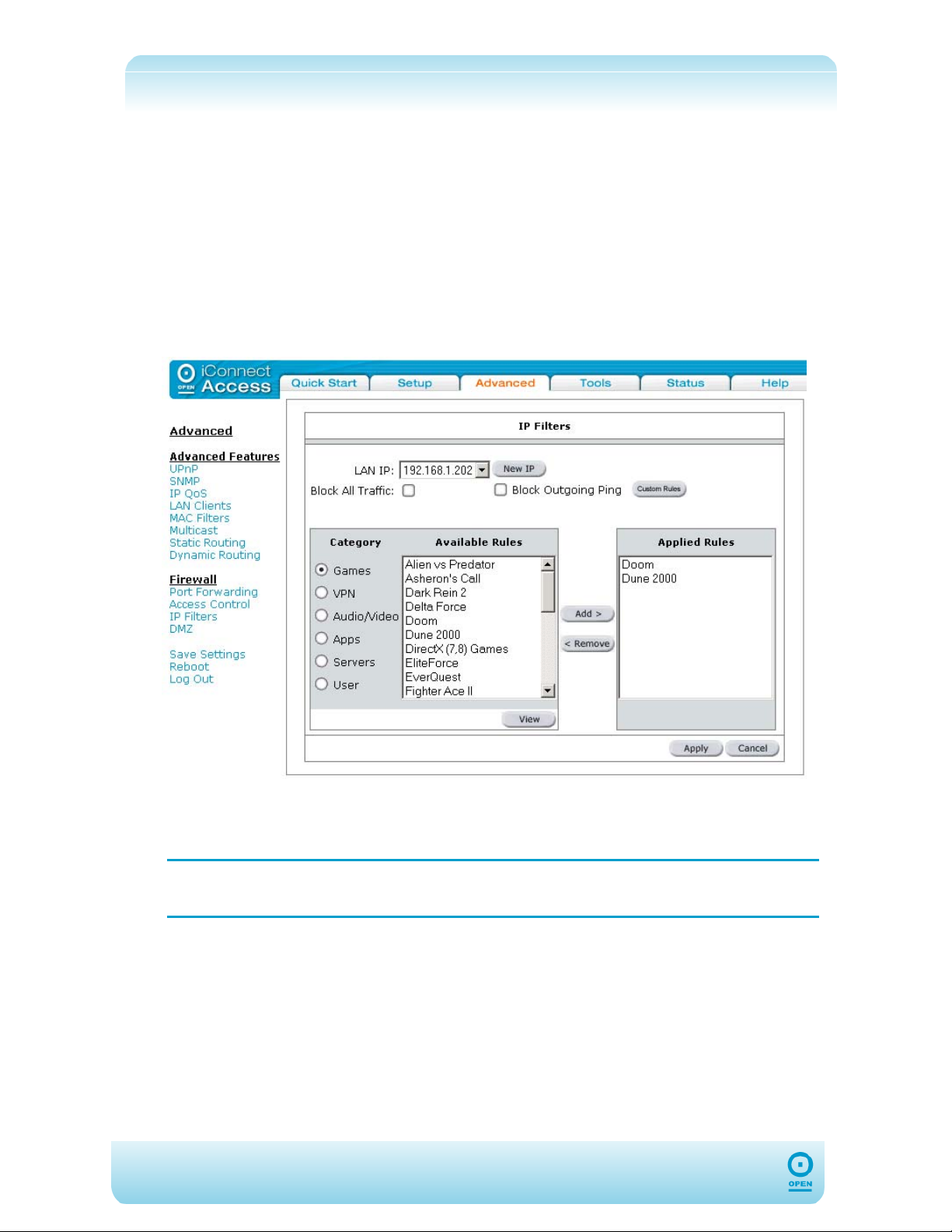
IP Filters
IP Filters allow you to block network access based on a user’s computer IP Address on the
LAN. You can use this option to block specific traffic (eg, to block web access) or any traffic
from a computer on your local network. If the traffic type is set to Any, all network traffic from
that computer will be blocked. You can also add / edit / delete IP Filter rules without using
the pre-defined rules. Click on Custom Rules to access this interface.
To Configure IP Filtering:
step 1 From the main screen, click Advanced.
step 2 From the Firewall menu, select IP Filters. The following appears:
step 3 From the LAN IP drop-down list, select the IP Address for which you wish to
apply the rule. If your IP address is not listed, click the New IP button, and
following the instructions in To Add A LAN Client:.
NOTE: It is recommended that Static IP Addresses rather than DHCP IP Addresses
be used for IP Filtering.
step 4 In the Category area of the screen, highlight the appropriate radio button for
the category. The Available Rules area displays common Internet services
within the category selected. Rules for each service can be viewed by clicking
the View button.
step 5 To add a rule for this connection, highlight the service or application from the
Available Rules window, then click Add. The rule then appears in the
Applied Rules area of the screen.
step 6 Click Apply to save the changes temporarily.
step 7 Click Save Settings from the menu list to save the rule permanently.
62
Page 63
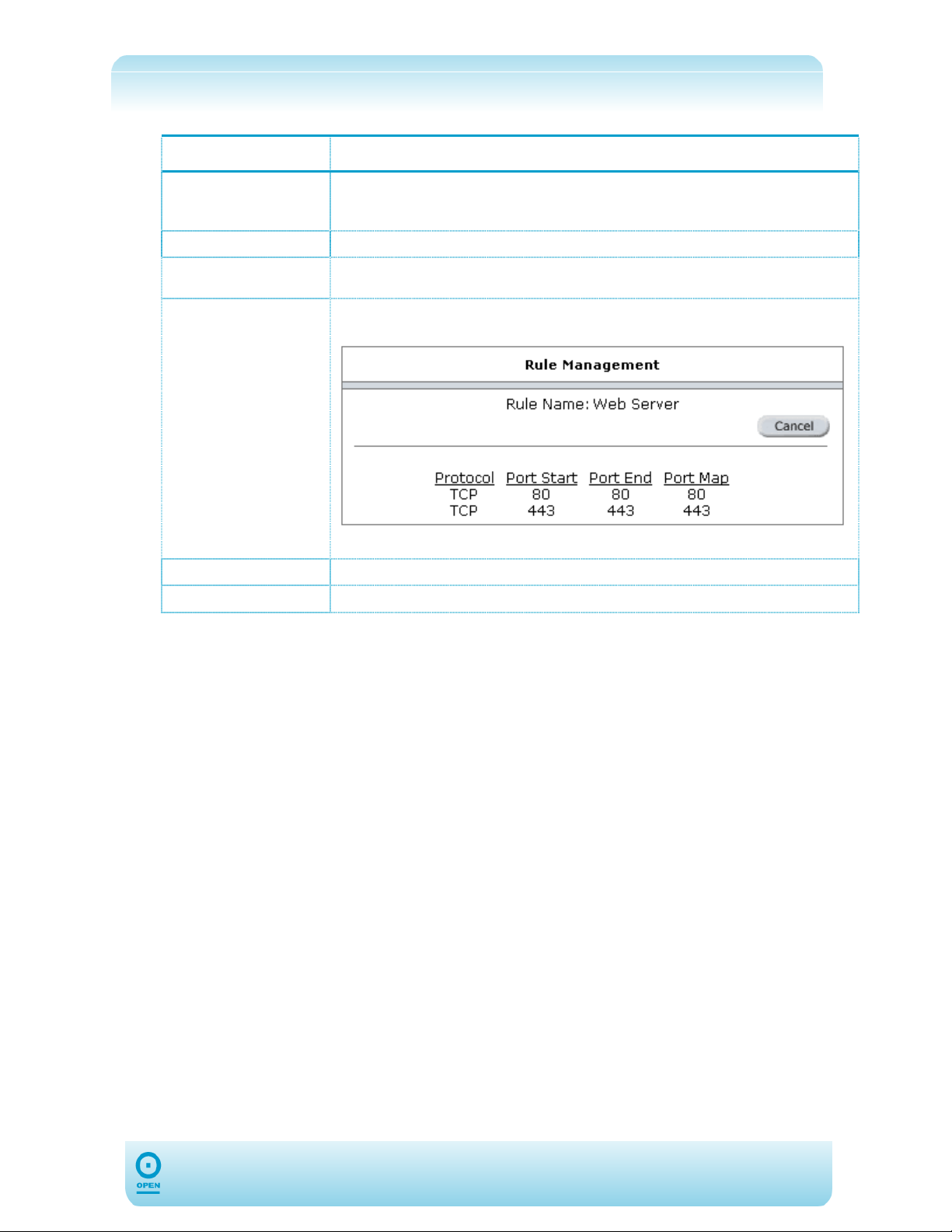
The following table lists the IP Filtering screen fields and their definitions:
Field Description
LAN IP
Block All Traffic
Block Outgoing
Ping
Category/Available
Rules
Applied Rules
Custom Rules
This is the server IP address to which Ports are forwarded. It is recommended
that you use a static IP address for Server. This address will need to be defined in
the LAN Clients screen. See To Add A LAN Client:
This option blocks all IP traffic from the specified LAN IP Address.
This option blocks ICMP traffic from the specified LAN IP Address.
A number of pre-defined categories and rules are available here. E.g.: Web
servers specifies the following port forwarding profile:
To view the details of a pre-defined rule, click View.
This specifies the applied IP filtering rule for the selected LAN IP Address.
You can specify custom IP Filtering rules by clicking the Custom Rule button.
63
Page 64
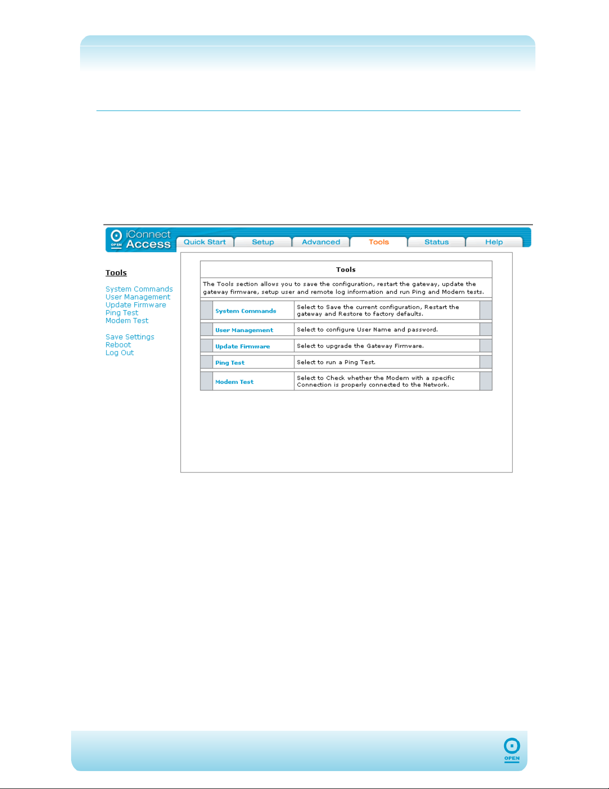
Tools
The Tools tab of the 624 web interface allows you to customise and debug your 624, update
the firmware and perform network diagnostics. Its options include:
System Commands;
User Management;
Update Firmware;
Ping Test;
Modem Test.
64
Page 65
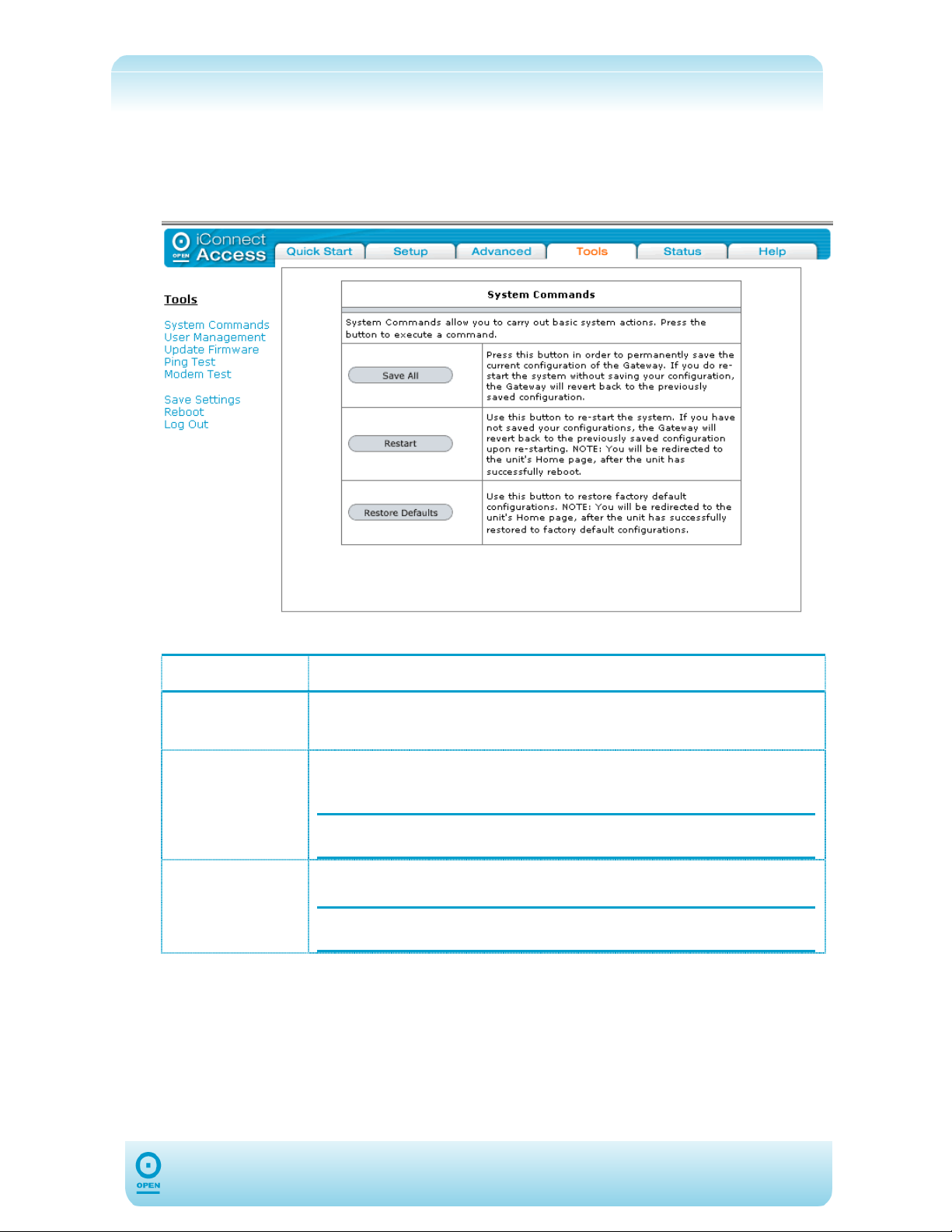
System Commands
To make changes permanent on the web interface you need to click the Tools tab and
select System Commands from the menu list. The following commands are used to
configure the 624:
The following table lists the System Commands screen buttons and their definitions:
Field Description
Save All
Restart
Restore
Defaults
Press this button to save the current configuration of the 624 permanently. If
you do restart the system without saving your configuration, the 624 will revert
back to the previously saved configuration.
Use this button to re-start the system. If you have not saved your configurations,
the 624 will revert back to the previously saved configuration upon re-starting.
NOTE: Connectivity to the unit will be lost. You can reconnect after
Use this button to restore the factory default configuration.
NOTE: Connectivity to the unit will be lost. You can reconnect after
the unit reboots.
the unit reboots.
65
Page 66
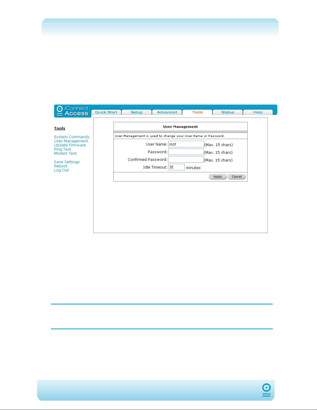
User Management
You can change your 624’s username and password by clicking User Management from
the Tools menu list. From here you can change the login name and password. You can
also change the idle timeout; you will need to log back onto the 624 once the timeout expires.
To Change The 624 Password:
step 1 From the main screen, click Tools, then User Management from the menu
list. The following screen appears:
step 2 Enter a user name for the root user in the User Name field.
step 3 Enter a password for the root user in the Password field.
step 4 Confirm the password by re-typing it in the Confirmed Password field.
step 5 If you wish to change the idle timeout, enter a new timeout in minutes in the
Idle Timeout field.
step 6 Click Apply to save the change temporarily.
step 7 Click Save Settings to make the change permanent.
If you forget your password, press and hold the reset to factory defaults button
NOTE:
for 10 seconds (or more). The 624 will reset to its factory default configuration
and all customised configurations will be lost.
66
Page 67
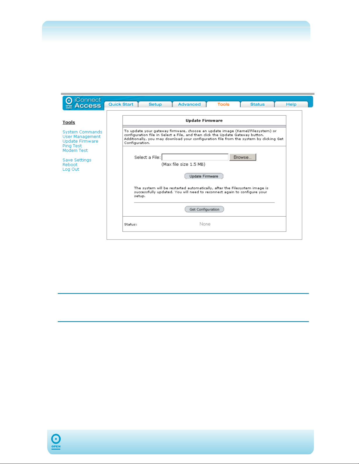
Update Firmware
To Upgrade The 624 Firmware:
step 1 From the main screen, click Tools, then Update Firmware from the menu
list. The following screen appears:
step 2 In the Update Firmware screen, click the Browse button beside the Select
A File field to search for the new firmware. Ensure the upgrade file is in
*.img format.
step 3 In the Choose File window, select the file and click Open.
step 4 Click Upgrade Firmware.
The firmware upgrade should take around five minutes to complete. Once
NOTE:
complete, the 624 will reboot, and you will then need to log back into it. Do not
remove power from the 624 during the firmware upgrade procedure.
67
Page 68
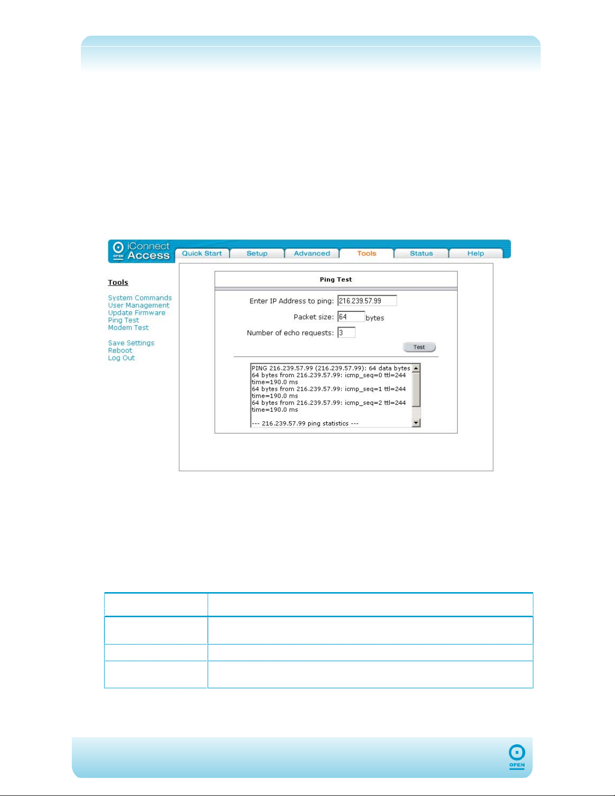
Ping Test
Ping is a diagnostic tool used to test connectivity between IP Hosts.
Once you have configured your 624, it is a good idea to ensure you can Ping the network. If
your ISP has provided its server address, you can try to ping this address. If the Pings for
both the WAN and LAN side complete and you have the proper protocols configured, you
should be able to surf the Internet.
To Perform A Ping Test:
step 1 From the main screen, click the Tools tab.
step 2 From the Tools menu list, click Ping Test. The following screen appears:
step 3 Enter the target address to be pinged in the Enter IP Address to ping
field.
step 4 In the Packet size field, enter the required packet size or leave at the default.
step 5 In the Number of echo requests field, enter the number of echo requests,
then click Test. The 624 will ping the specified address, and you will be able to
see the results in the display area beneath the Test button.
The following table lists the Ping Test screen fields and their definitions:
Field Description
Enter IP address
to ping
Packet size
Number of echo
requests
This is the IP address of the destination device that you want to ping. If the
ping is successful, it means that the 624 has IP connectivity to this device.
The packet size can be defined for the Ping request.
The number of ping packets that you want to send in the sequence.
68
Page 69
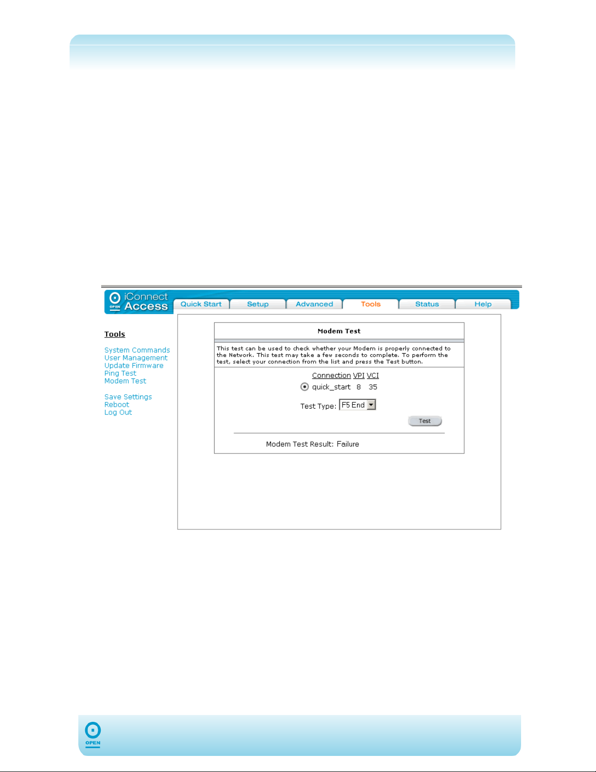
Modem Test
The Modem Test menu item allows you to check whether your 624 is properly connected to
the WAN Network. There are four test types, each of which may take a few seconds to
complete.
The OAM loopback cells are used to verify the connection between the 624 and the ATM
network. For the 624, OAM loopback provides a valuable tool for diagnosing problems with
the DSL line at the ATM layer.
Before you attempt any of these modem tests, ensure the following:
Your DSL Provider / ISP supports them;
You have a valid DSL link.
To Perform A Modem Test:
step 1 From the main screen, click the Tools tab.
step 2 From the Tools menu list, click Modem Test. The following screen appears:
step 3 Select your connection from the list.
step 4 Select the type of test to perform from the Test Type drop-down list, then click
Test.
69
Page 70
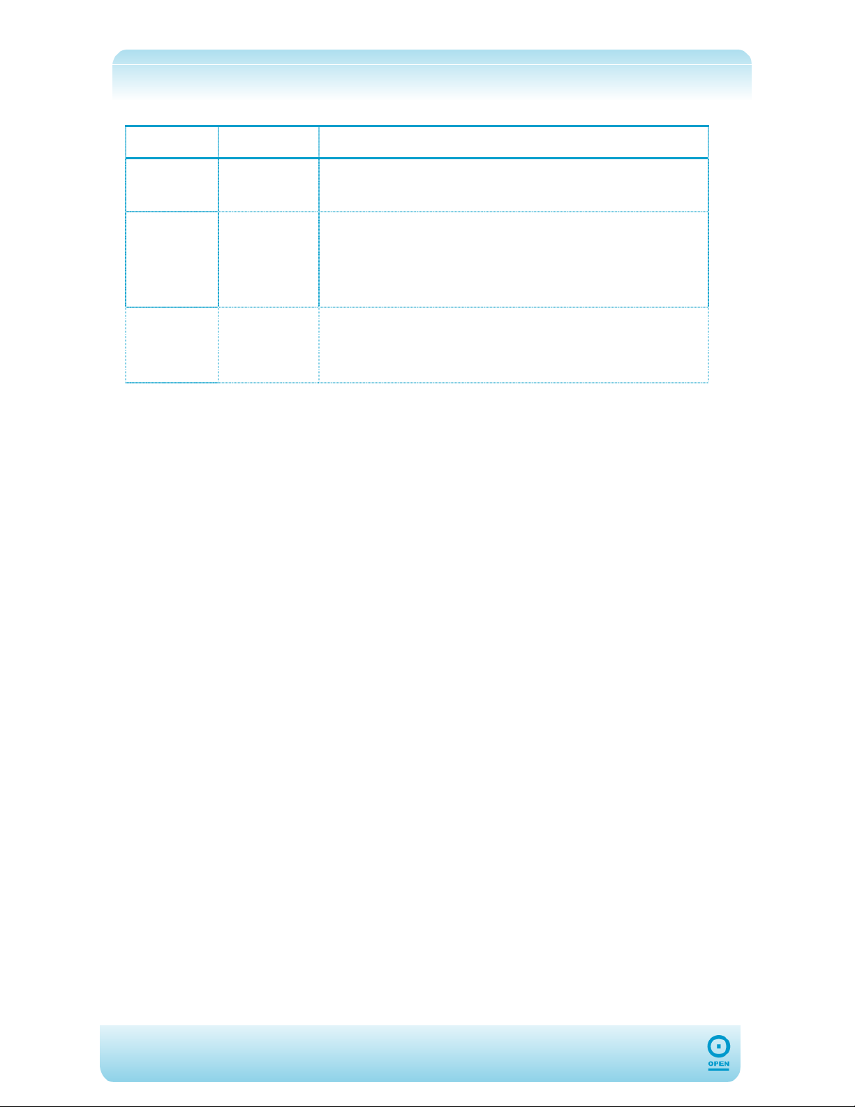
The following table lists the Modem Test screen Test Type field and its definitions:
Field Options Description
Test Type F5 End
F5 Seg
F4 End and
F4 Seg
Tests
Connectivity to the BRAS server can be verified by initiating
a F5 Seg loopback via the DSLAM and to the authentication
server.
Lost and corrupted ATM cells can be quickly ruled out in the field
by initiating a F5 Seg loopback (also known as ATM ping) to the
DSLAM and have the DSLAM respond by looping back the OAM
cells. By ruling out problems with the ATM Layer, the service
provider can then focus on examining higher layer protocols and
other configurations to isolate the problem.
You can perform two types of OAM F4 Tests:
Segment—the end of a connection segment
End-to-end—the end of a VC/VP connection where the ATM cells
are terminated
70
Page 71
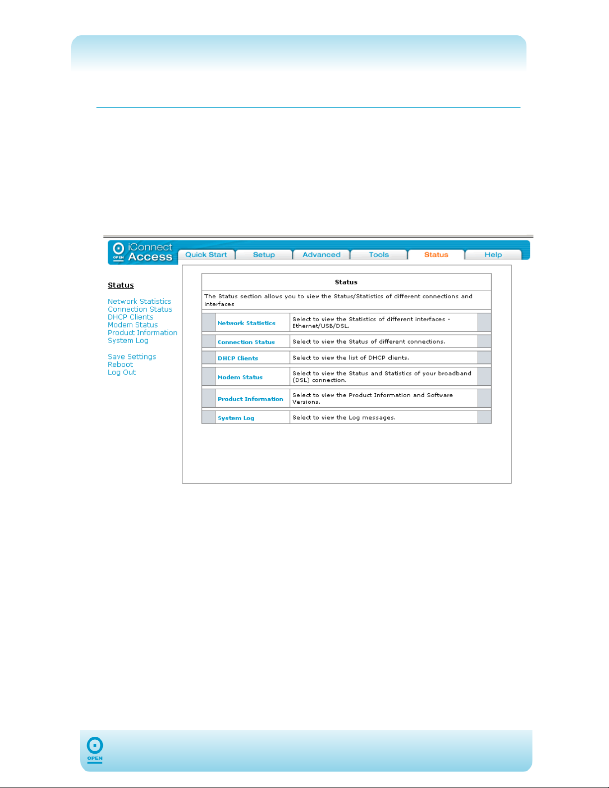
Status
The Status tab of the 624 web interface allows you to view the Status/Statistics of different
connections and interfaces, and consists of the following:
Network Statistics;
Connection Status;
DHCP Clients;
Modem Status;
Product Information;
System Log.
71
Page 72
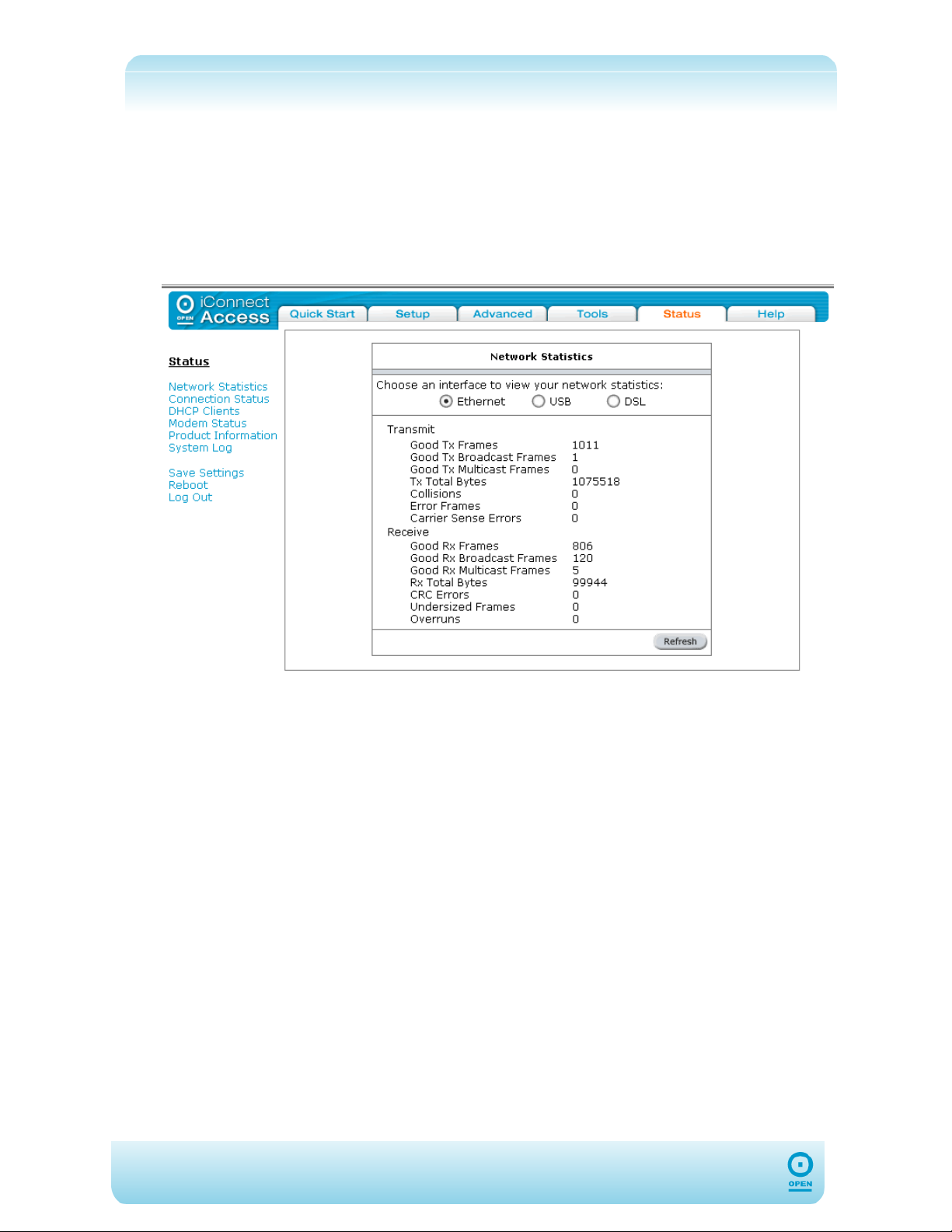
Network Statistics
The Network Statistics area will show you details of transmitted and received packets.
To View Network Statistics:
From the main screen, click the Status tab.
From the Status main screen, click Network Statistics. The following
screen appears:
In the Network Statistics screen, highlight the appropriate radio button
corresponding to view network statistics for Ethernet, USB or DSL. Click
Refresh.
72
Page 73
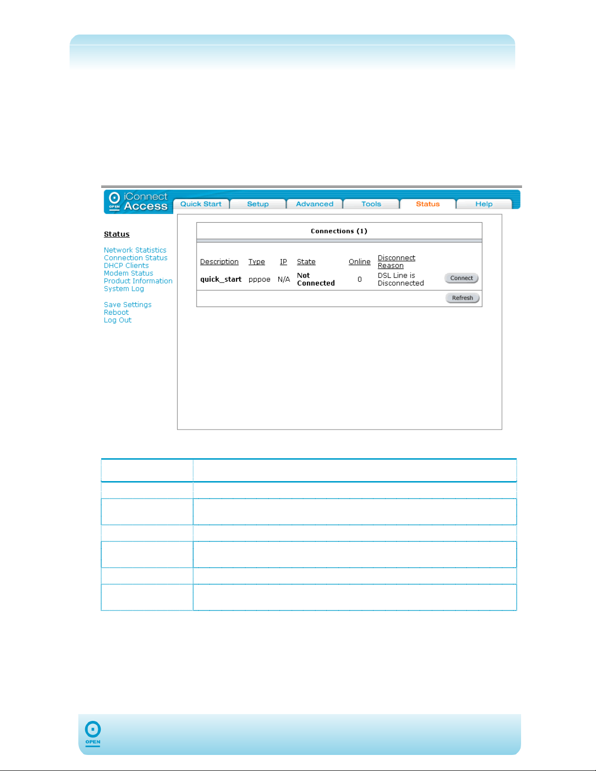
Connection Status
The Connection Status screen displays a status summary of the ADSL connection.
To View Connection Status:
From the main screen, click the Status tab.
From the Status main screen, click Connection Status. The following screen
appears:
The following table lists the Connections screen fields and their definitions:
Field Description
Description
Type
IP
State
Online
Disconnect
Reason
This is the name of the connected ADSL profile.
Authentication type of the ADSL connection is listed here. E.g.: PPPoE, PPPoA,
Static etc:
The WAN IP Address is displayed here when the connection is established.
ADSL connection status is displayed here. This is the connection between your
624 and the DSLAM at your ISP. In normal operation, this must be connected.
The duration of the Internet connection time for the Connection type specified.
If the ADSL is disconnected, the reason for disconnection is displayed here.
73
Page 74
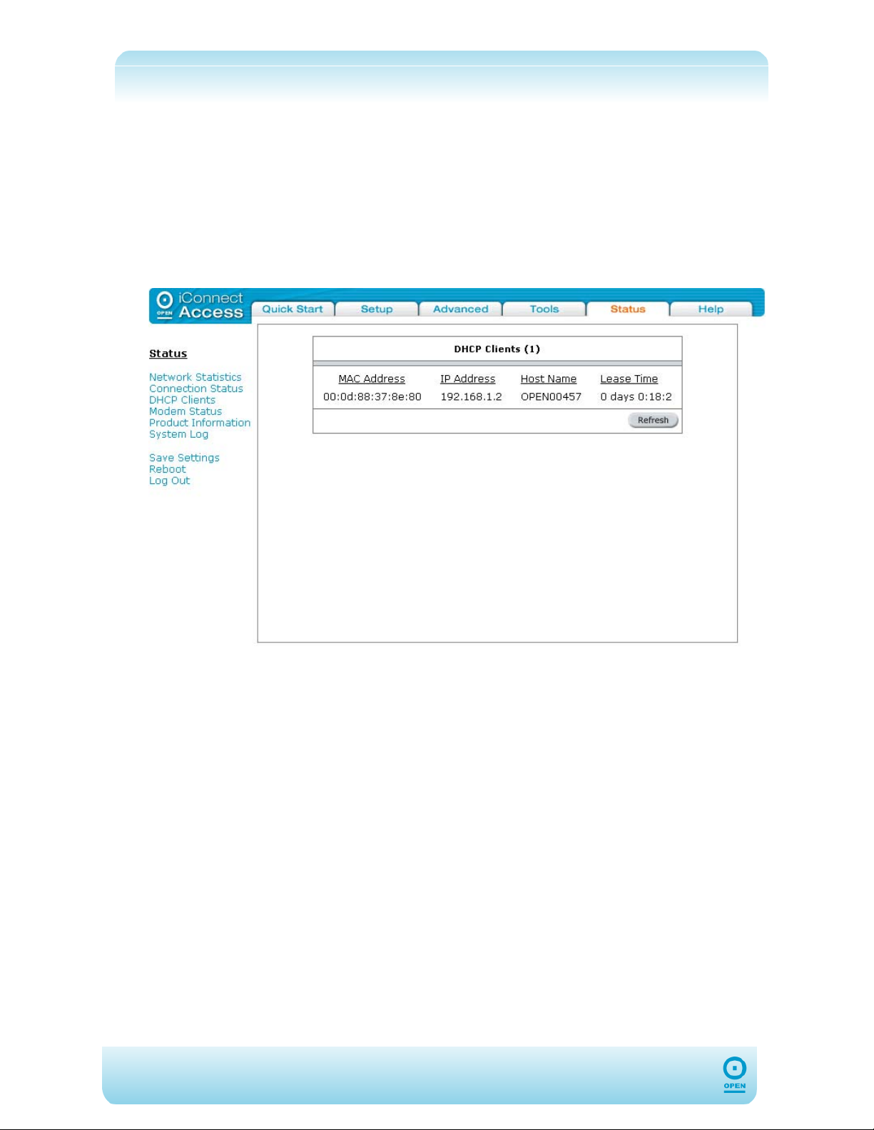
DHCP Clients
Select the DHCP Clients menu item from the Status menu list to view the list of DHCP
clients.
To View DHCP Clients:
From the main screen, click the Status tab.
From the Status main screen, click DHCP Clients.
The following screen appears:
74
Page 75
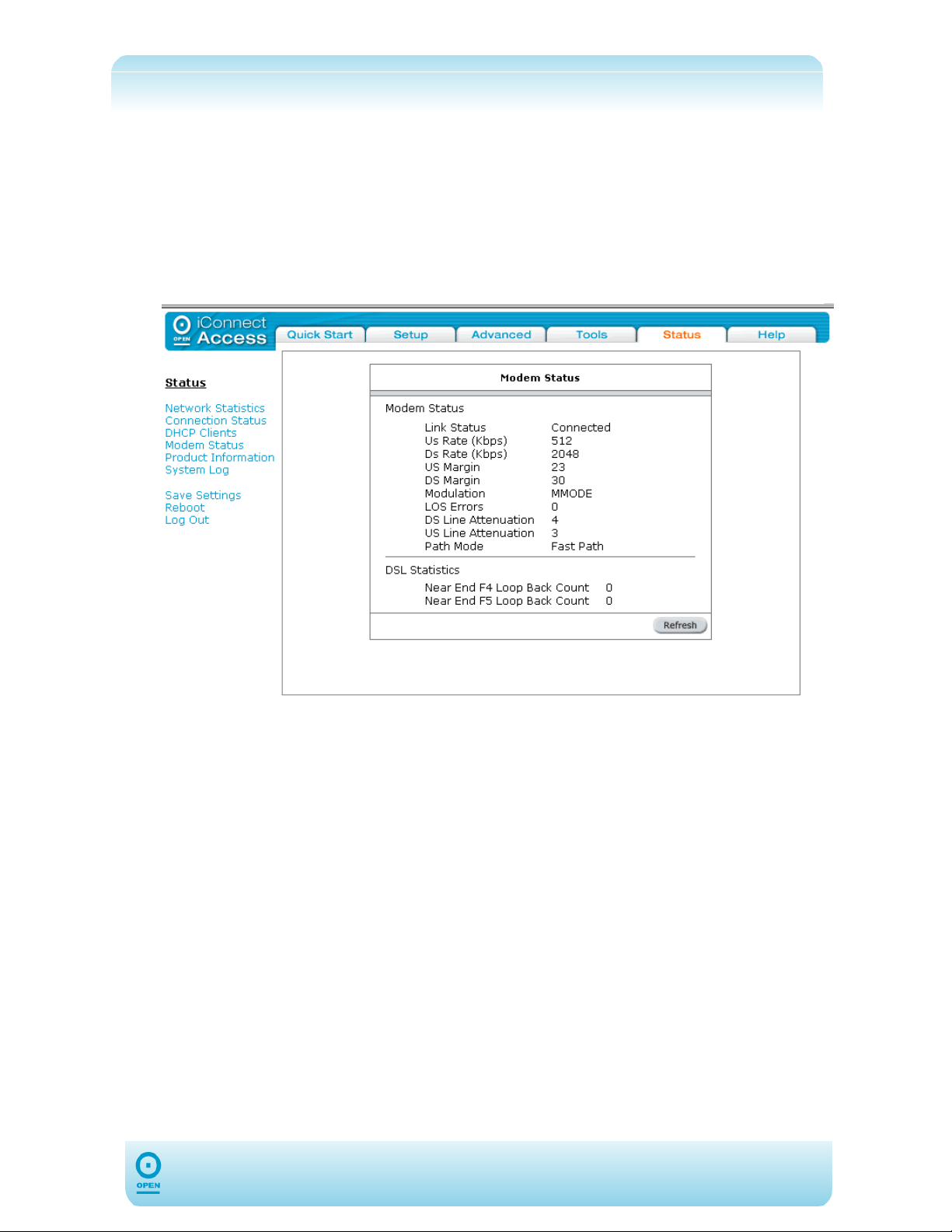
Modem Status
Select the Modem Status menu item from the Status menu list to view the Status and
Statistics of your broadband (DSL) connection.
To View The Modem Status:
From the main screen, click Status.
From the Status main screen, click Modem Status. The following screen
appears:
75
Page 76
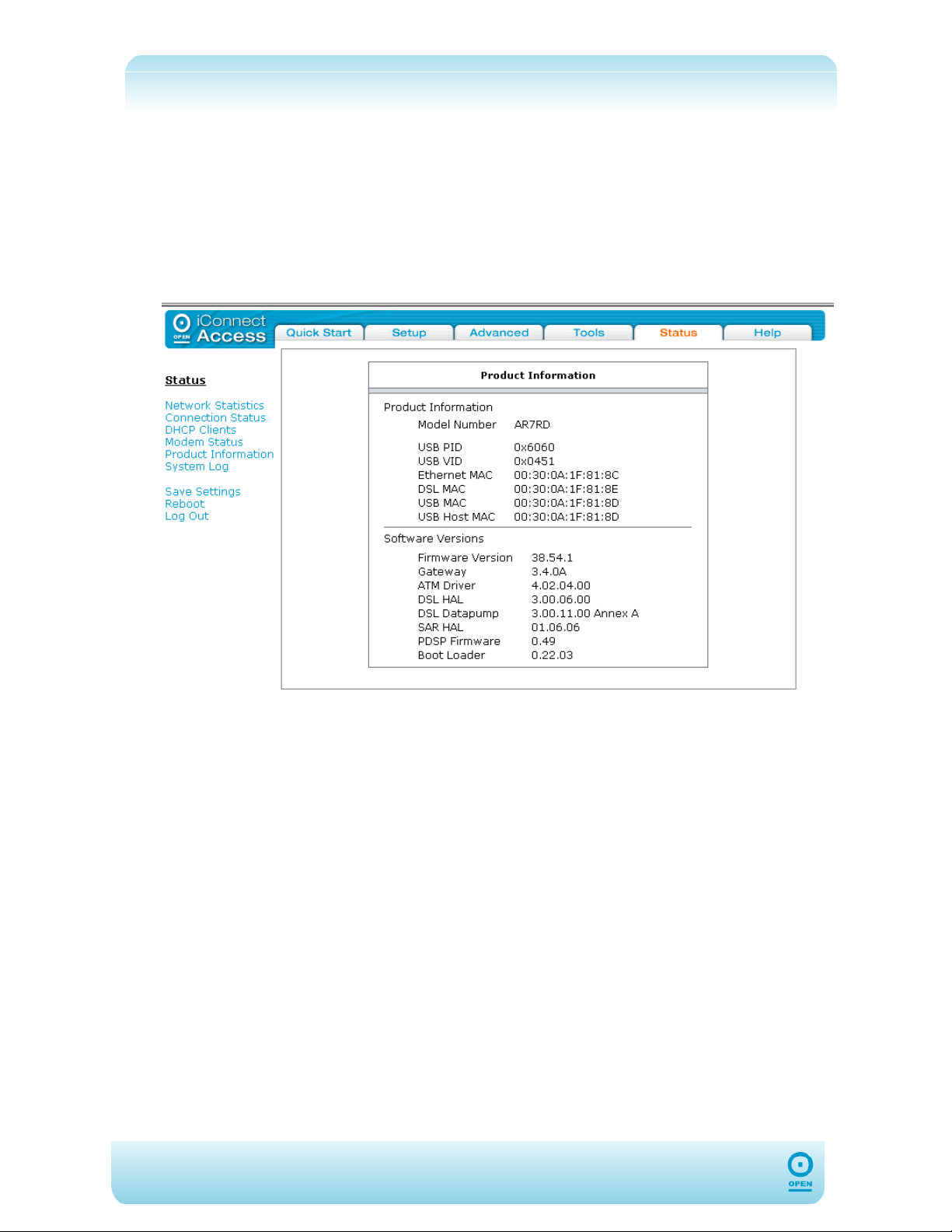
Product Information
You can verify product information such as model, driver, hardware and software versions in
the Product Information area of the web interface.
To View 624 Product Information:
From the main screen, click Status.
From the Status main screen, click Product Information. The following
screen appears:
76
Page 77
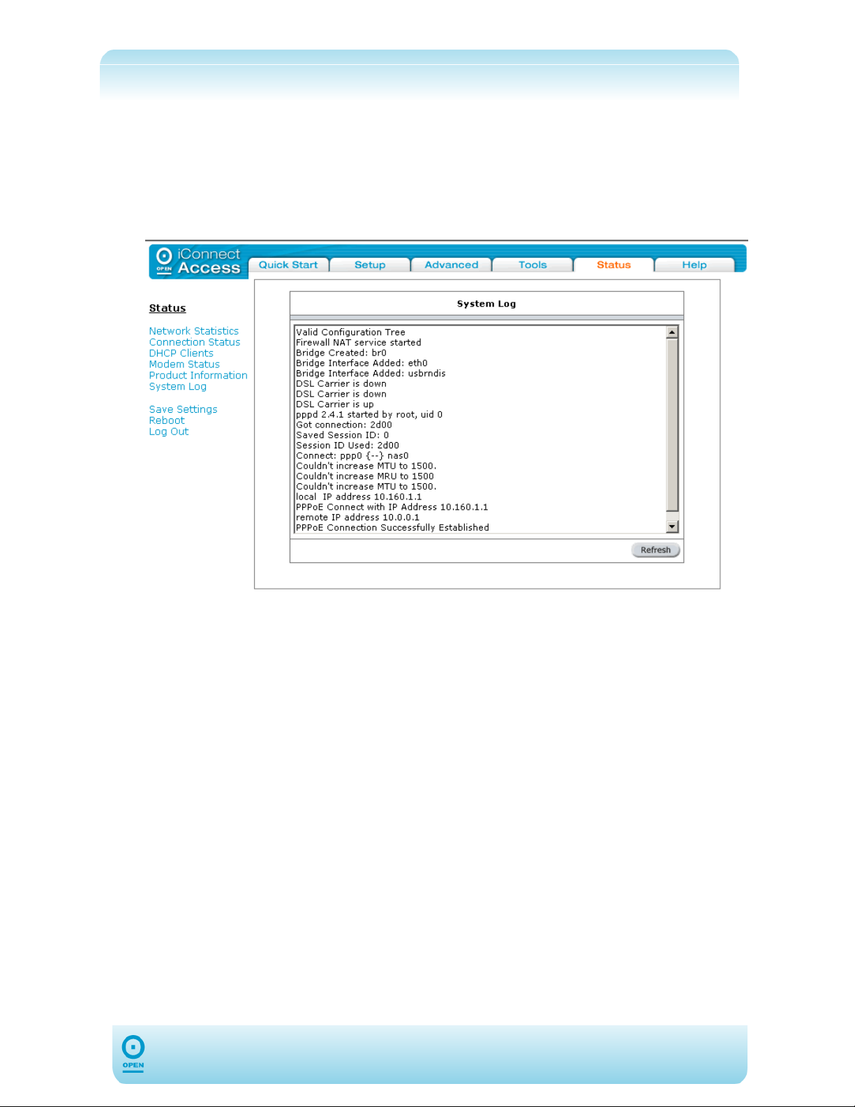
System Log
You can view all logged information in the System Log area of the web interface.
To Display The 624 System Log:
From the main screen, click the Status tab.
From the Status menu, click System Log. The following screen appears:
77
Page 78

Index
624 Log In, 14
624 Ports and Buttons, 6
624 Ports And Buttons
ADSL, 6
DC, 6
Ethernet, 6
Reset, 6
624, Installation Of, 9
624, Setting Up, 13
Advanced Security Features
Incoming ICMP Ping, 38
Advanced Tab, 39
Dynamic Routing, Enabling, 54
Firewall, 56
IP QoS, Configuration Of, 43
LAN Clients, Adding, 47
MAC Filter Rules, Hidden, 49
LAN Configuration
DHCP Enable / Disable, 17
Management IP Configuration, 19
LAN, Configuration Of, 17
Modem Set Up
ADSL Handshake, 37
Quick Start Tab, 15
Setting Up Your 624
Default Settings, 13
Status Tab, 71
Connection Status, 73
DHCP Clients, 74
Modem Status, 75
Network Statistics, 72
Product Information, 76
System Log, 77
Tools Tab, 64
MAC Filters, 48
Multicast, Enabling, 50
SNMP Configuration Of, 41
Static Routing, Enabling, 52
UPnP, 39
Ethernet Configuration
Windows 2000 / XP, 12
Windows 98 Second Edition / ME, 11
Ethernet Network Card, Configuration
Of, 11
Firewall
Access Control, 59
DMZ, Configuration Of, 61
IP Filters, 62
Port Forwarding, 56
Front LED Panel, 8
Firmware Upgrade, 67
Modem Test, 69
Ping Test, 68
System Commands, 65
User Management, 66
WAN Configuration
Bridged Connection Type, 28
Classical IP Over ATM (CLIP)
Connection, 36
Connection, Modification Of, 37
DHCP Connection, 34
PPPoA Connection, 25
PPPoE Connection, 22
Static Connection, 31
WAN, Configuration Of, 21
78
 Loading...