

Page 1

Introduction .................................... 2
In brief ............................................ 6
Keys, doors and windows ............ 17
Seats, restraints ........................... 30
Storage ........................................ 51
Instruments and controls ............. 59
Lighting ........................................ 76
Climate control ............................. 83
Driving and operating ................... 94
Vehicle care ............................... 116
Service and maintenance .......... 149
Technical data ........................... 152
Customer information ................ 170
Index .......................................... 172
Contents
Page 2
2 Introduction
Introduction
Page 3

Introduction 3
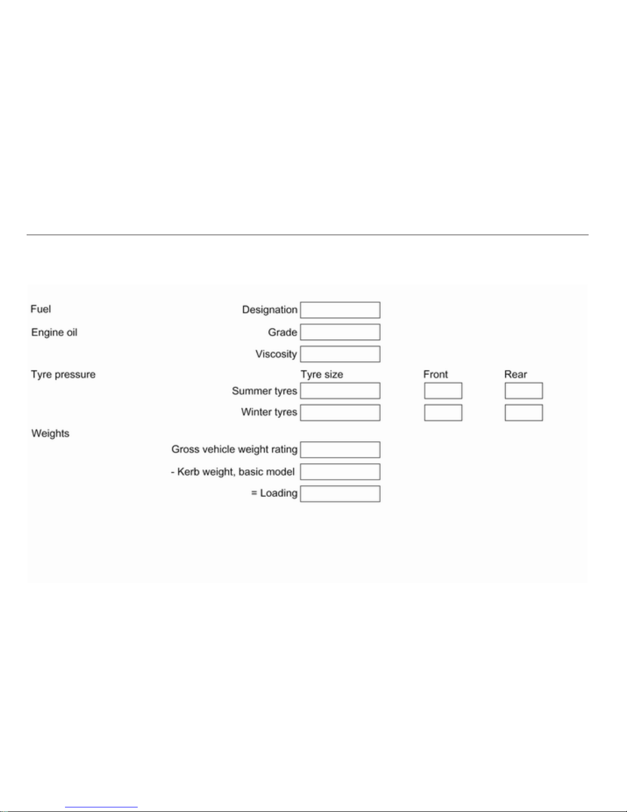
Vehicle specific data
Please enter your vehicle's data on
the previous page to keep it easily
accessible. This information is
available in the sections "Service and
maintenance" and "Technical data"
as well as on the identification plate.
Introduction
Your vehicle is a designed
combination of advanced technology,
safety, environmental friendliness
and economy.
This Owner's Manual provides you
with all the necessary information to
enable you to drive your vehicle
safely and efficiently.
Make sure your passengers are
aware of the possible risk of accident
and injury which may result from
improper use of the vehicle.
You must always comply with the
specific laws and regulations of the
country that you are in. These laws
may differ from the information in this
Owner's Manual.
When this Owner's Manual refers to
a workshop visit, we recommend your
Opel Service Partner.
All Opel Service Partners provide
first-class service at reasonable
prices. Experienced mechanics
trained by Opel work according to
specific Opel instructions.
The customer literature pack should
always be kept ready to hand in the
vehicle.
Using this manual
■ This manual describes all options
and features available for this
model. Certain descriptions,
including those for display and
menu functions, may not apply to
your vehicle due to model variant,
country specifications, special
equipment or accessories.
■ The "In brief" section will give you
an initial overview.
■ The table of contents at the
beginning of this manual and within
each section shows where the
information is located.
■ The index will enable you to search
for specific information.
■ This Owner's Manual depicts lefthand drive vehicles. Operation is
similar for right-hand drive vehicles.
■ The Owner's Manual uses the
factory engine designations. The
corresponding sales designations
can be found in the section
"Technical data".
■ Directional data, e.g. left or right, or
front or back, always relate to the
direction of travel.
■ The vehicle display screens may
not support your specific language.
■ Display messages and interior
labelling are written in bold letters.
Danger, Warnings and
Cautions
9 Danger
Text marked 9 Danger provides
information on risk of fatal injury.
Disregarding this information may
endanger life.
Page 4
4 Introduction
9 Warning
Text marked 9 Warning provides
information on risk of accident or
injury. Disregarding this
information may lead to injury.
Caution
Text marked Caution provides
information on possible damage to
the vehicle. Disregarding this
information may lead to vehicle
damage.
Symbols
Page references are indicated with 3.
3 means "see page".
We wish you many hours of
pleasurable driving.
Adam Opel AG
Page 5

Introduction 5
Page 6
6 In brief
In brief
Initial drive information
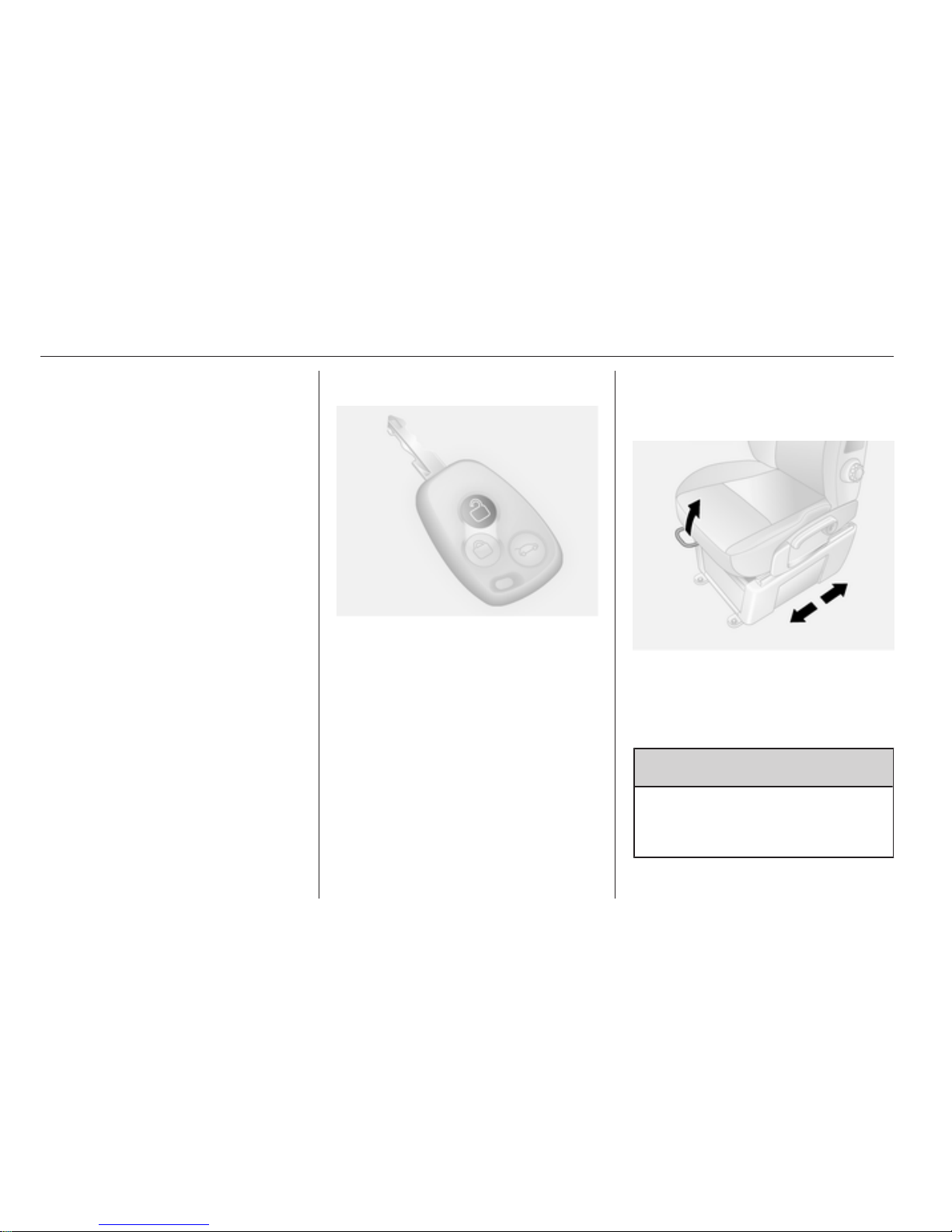
Vehicle unlocking
Press button c to unlock the doors.
Open the doors by pulling the
handles.
Press button G; only the load
compartment is unlocked.
Radio remote control 3 17, Central
locking system 3 18, Anti-theft
alarm system 3 23.
Seat adjustment
Seat positioning
Pull handle, slide seat, release
handle.
Seat position 3 31, Seat adjustment
3 32.
9 Danger
Do not sit nearer than 25 cm from
the steering wheel, to permit safe
airbag deployment.
Page 7
In brief 7
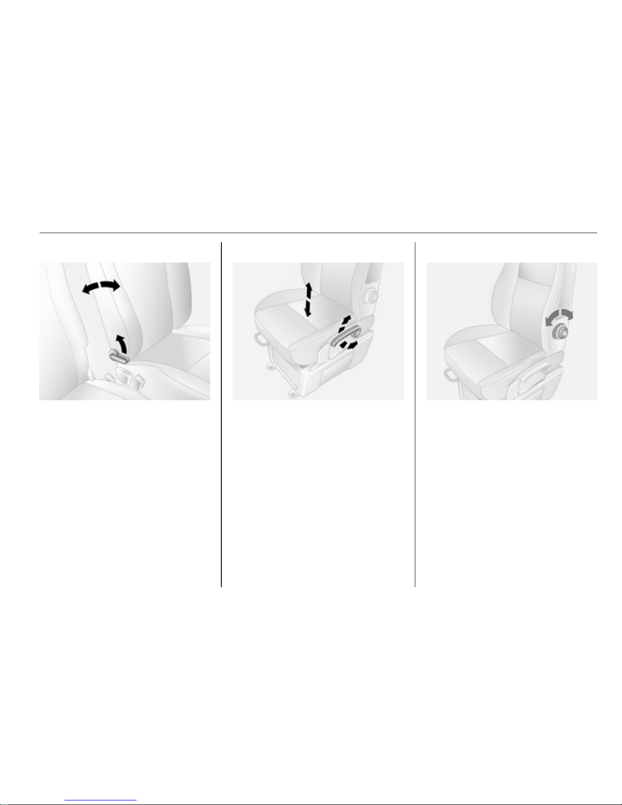
Seat backrests
Pull lever, adjust inclination and
release lever. Allow the seat to
engage audibly.
Seat position 3 31, Seat adjustment
3 32.
Seat height
Lever motion
up = seat higher
down = seat lower
Seat position 3 31, Seat adjustment
3 32.
Lumbar support
To adjust, turn the handwheel.
Seat position 3 31, Seat adjustment
3 32.
Page 8
8 In brief
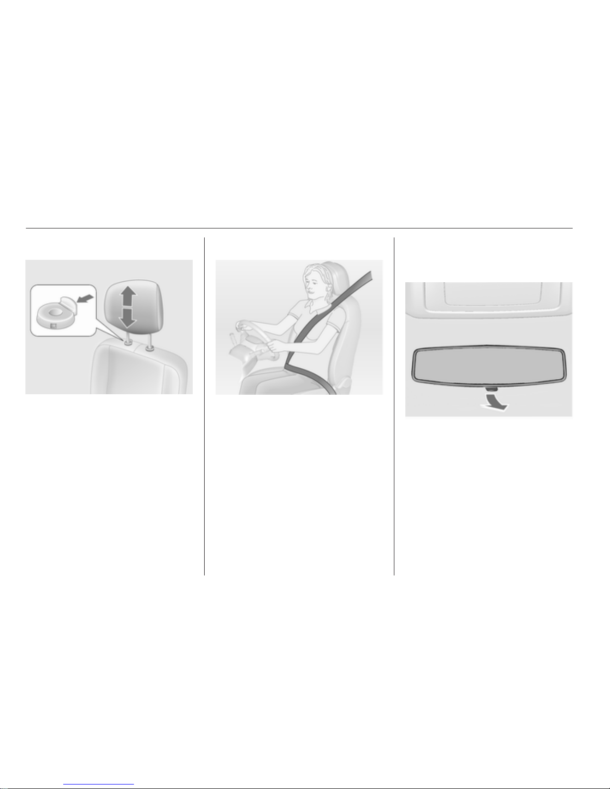
Head restraint adjustment
Press release catch, adjust height,
engage.
Head restraints 3 30.
Seat belt
Pull out the seat belt and engage in
belt buckle. The seat belt must not be
twisted and must fit close against the
body. The backrest must not be tilted
back too far (maximum approx. 25 °).
To release belt, press red button on
belt buckle.
Seat position 3 31, Seat belts
3 37, Airbag system 3 40.
Mirror adjustment
Interior mirror
Adjust the lever on the underside to
reduce dazzle.
Interior mirror 3 26.
Page 9
In brief 9
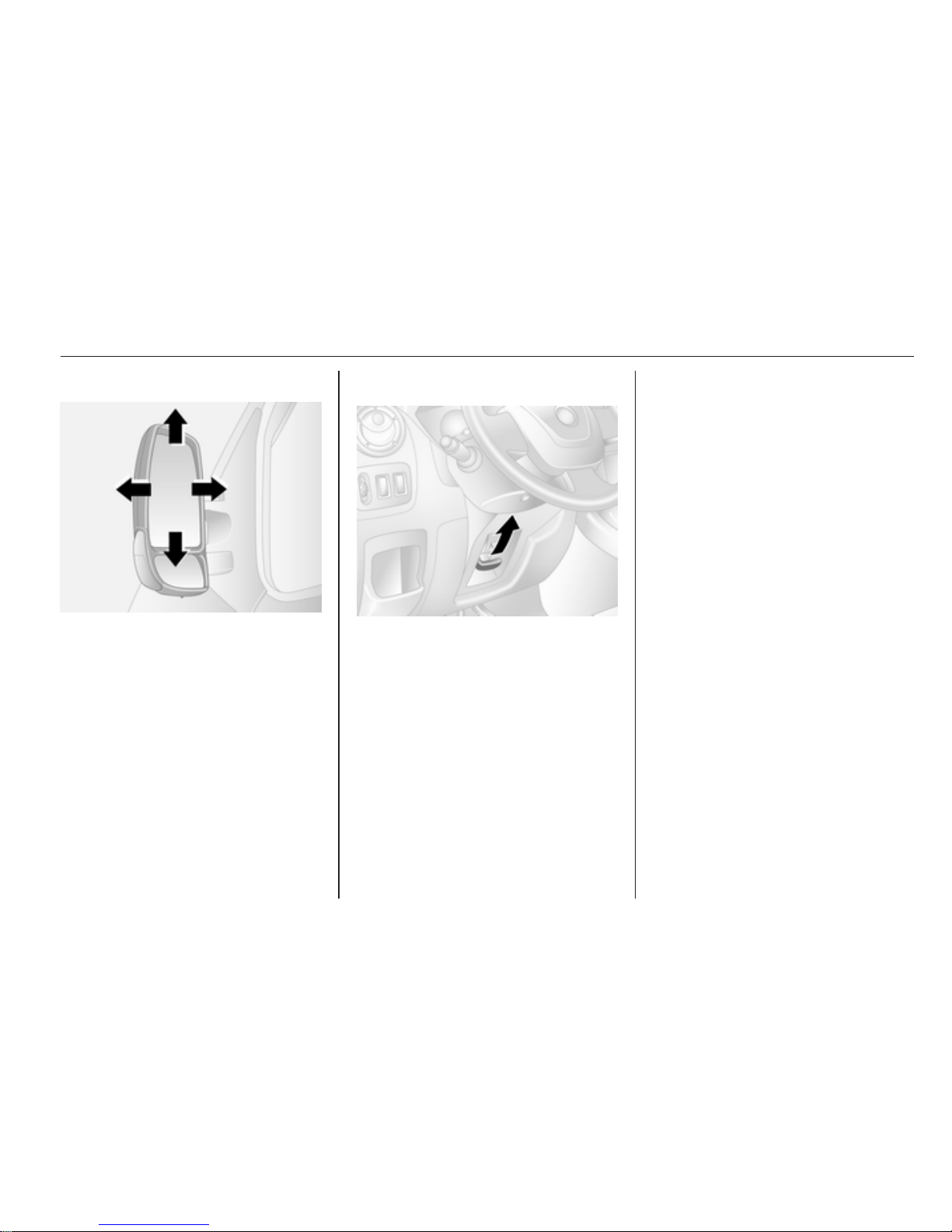
Exterior mirrors
Select the relevant exterior mirror and
adjust.
Convex exterior mirrors 3 25,
Electric adjustment 3 25, Heated
exterior mirrors 3 26.
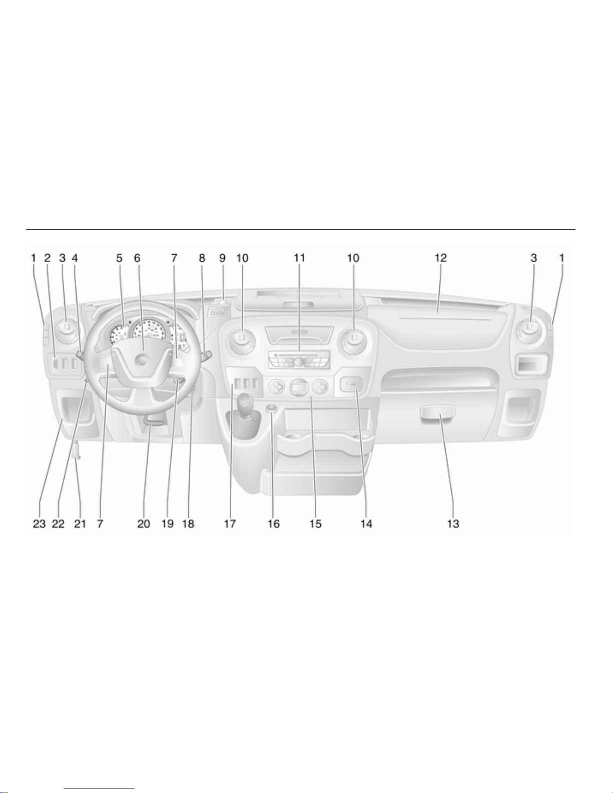
Steering wheel adjustment
Unlock lever, adjust steering wheel,
then engage lever and ensure it is
fully locked.
Do not adjust steering wheel unless
vehicle is stationary and steering
wheel lock has been released.
Airbag system 3 40, Ignition
positions 3 95.
Page 10
10 In brief
Page 11
In brief 11
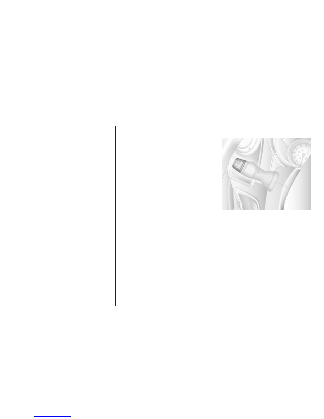
Instrument panel overview
1 Fixed air vents ...................... 92
2 Headlight range
adjustment ........................... 77
Parking assist ..................... 109
Traction Control system ..... 104
Electronic stability program 105
3 Side air vents ....................... 92
4 Turn and lane-change
signals .................................. 78
High beam and low beam,
headlight flash ...................... 77
Automatic light control .......... 76
Exit lighting ........................... 81
Front fog lights ..................... 78
Rear fog light ........................ 79
5 Instruments .......................... 64
6 Horn ..................................... 60
Driver airbag ........................ 40
7 Steering wheel controls ....... 59
Cruise control ..................... 106
8 Windscreen wiper,
windscreen washer system ..60
9 Power outlet ......................... 63
10 Centre air vents .................... 92
11 Infotainment system ............. 10
12 Passenger airbag ................. 40
13 Glovebox .............................. 52
Storage compartment .......... 51
14 AUX input ............................. 10
15 Climate control system ......... 83
16 Cigarette lighter .................... 63
17 Cruise control and speed
limiter ................................. 106
Manual transmission
automated,
Winter and Laden modes .... 101
Idle speed control ................. 95
18 Ignition switch with
steering wheel lock .............. 95
19 Steering column controls .....60
20 Steering wheel adjustment ..59
21 Bonnet release lever .......... 117
22 Auxiliary heater ..................... 88
23 Fuse box ............................ 132
Exterior lighting
Turn light switch
7
= Off
0
= Sidelights
9 P
= Headlights
AUTO = Automatic light control:
Headlights are switched
on and off automatically.
Turn
>
= Front fog lights
r
= Rear fog lights
Lighting 3 76.
Page 12

12 In brief
Headlight flash, high beam and
low beam
Pull lever.
High beam 3 77, Headlight flash
3 77.
Turn and lane-change signals
right = lever up
left = lever down
Turn and lane-change signals
3 78.
Hazard warning flashers
Operated with the ¨ button.
Hazard warning flashers 3 78.
Page 13
In brief 13
Horn
Press j.
Washer and wiper systems
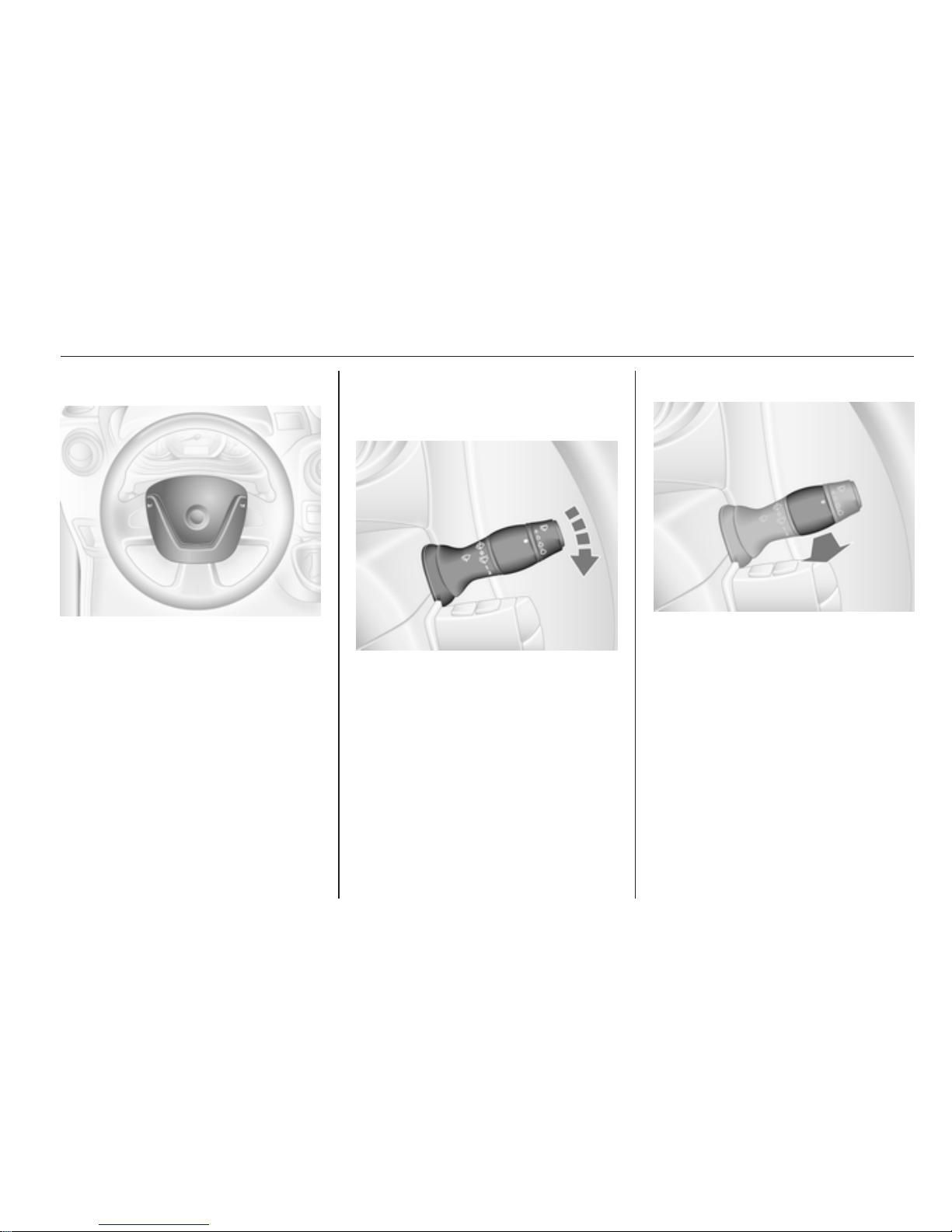
Windscreen wiper
0 = off
P
= timed interval wiping or
automatic wiping with rain
sensor
1 = slow
2 = fast
Windscreen wiper 3 60, Wiper
blade replacement 3 122.
Windscreen washer
Pull lever.
Windscreen washer 3 60, Washer
fluid 3 120.
Page 14
14 In brief
Climate control
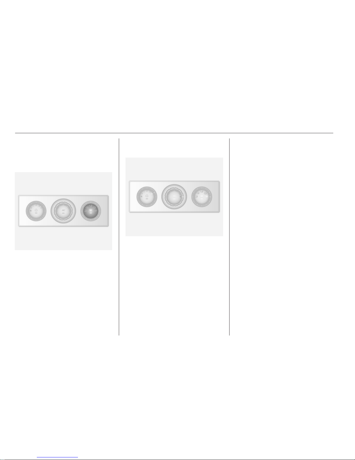
Heated rear window, heated
exterior mirrors
Heating is operated by pressing the
Ü button.
Heated exterior mirrors 3 26,
Heated rear window 3 28.
Demisting and defrosting the
windows
Air distribution to V.
Set temperature control to warmest
level.
Set fan speed to highest level.
Cooling AC on.
Press button Ü.
Climate control system 3 83.
Vehicles with Electronic climate
control, press button V.
Temperature and air distribution are
set automatically and the fan runs at
a high speed.
Electronic climate control system
3 84.
Page 15
In brief 15
Transmission
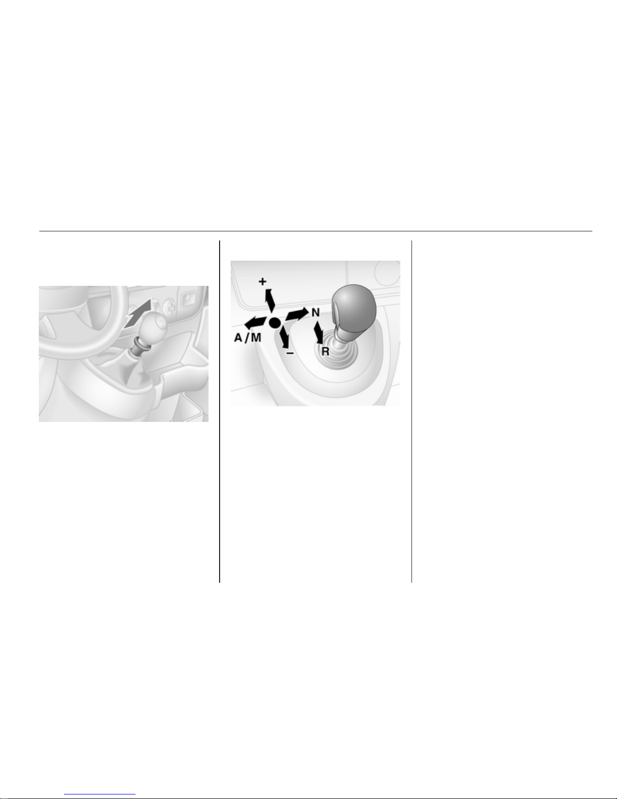
Manual transmission
Reverse: with the vehicle stationary,
depress clutch pedal and then pull up
the collar on the selector lever and
engage the gear.
If the gear does not engage, set the
lever to neutral, release the clutch
pedal and depress again; then repeat
gear selection.
Manual transmission 3 98.
Manual transmission automated
N = neutral
o
= drive
+ = higher gear
- = lower gear
A/M = switch between automatic
and manual mode
R = reverse gear
Manual transmission automated
3 98.
Starting off
Check before starting off
■ Tyre pressure and condition 3 135,
3 167.
■ Engine oil level and fluid levels
3 118.
■ All windows, mirrors, exterior
lighting and number plates are free
from dirt, snow and ice and are
operational.
■ Proper position of mirrors, seats
and seat belts 3 25, 3 31,
3 38.
■ Brake function at low speed,
particularly if the brakes are wet.
Page 16
16 In brief
Starting the engine
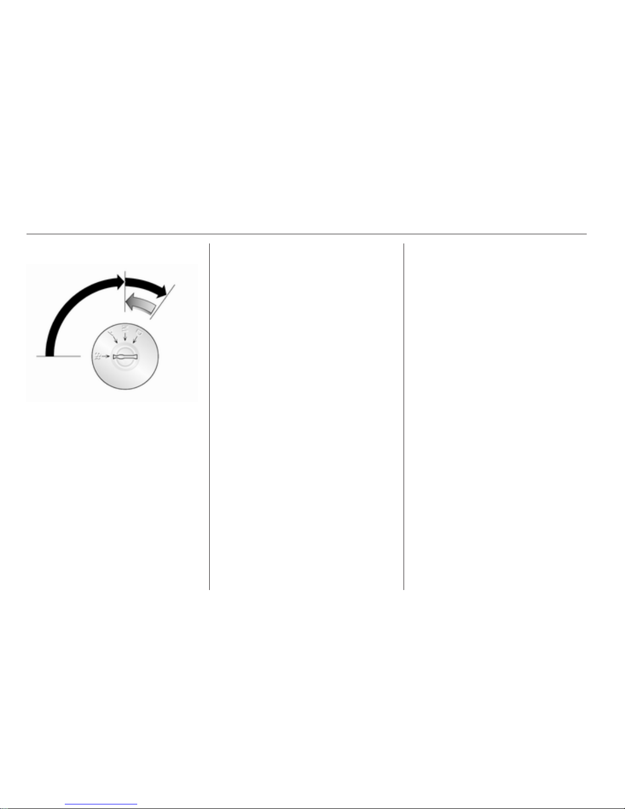
■ Turn key to position A
■ move the steering wheel slightly to
release the steering wheel lock
■ operate clutch and brake
■ do not accelerate
■ turn the key to position M for
preheating and wait until control
indicator ! goes out
■ turn key to D and release
Starting the engine 3 95.
Parking
■ Always apply parking brake without
pressing release button. Apply as
firmly as possible on a downhill
slope or uphill slope. Depress foot
brake at the same time to reduce
operating force.
■ Switch off the engine. Turn the
ignition key to St and remove it.
Turn the steering wheel until the
steering wheel lock is felt to
engage.
■ If the vehicle is on a level surface or
uphill slope, engage first gear
before switching off the ignition. On
an uphill slope, turn the front
wheels away from the kerb.
If the vehicle is on a downhill slope,
engage reverse gear before
switching off the ignition. Turn the
front wheels towards the kerb.
■
Lock the vehicle with button e on
the radio remote control.
■ Do not park the vehicle on an easily
ignitable surface. The high
temperature of the exhaust system
could ignite the surface.
■ Close the windows.
■ The engine cooling fans may run
after the engine has been switched
off 3 117.
■ After running at high engine speeds
or with high engine loads, operate
the engine briefly at a low load or
run in neutral for approx.
30 seconds before switching off, in
order to protect the turbocharger.
Keys, locks 3 17, Laying the vehicle
up for a long period of time 3 116.
Page 17
Keys, doors and windows 17
Keys, doors and
windows
Keys, locks ................................... 17
Doors ........................................... 21
Vehicle security ............................ 23
Exterior mirrors ............................ 25
Interior mirrors ............................. 26
Windows ...................................... 27
Roof ............................................. 29
Keys, locks
Keys
Replacement keys
The key number is specified in the
Car Pass or on a detachable tag.
The key number must be quoted
when ordering replacement keys as it
is a component of the immobiliser
system.
Locks 3 146.
Car Pass
The Car Pass contains security
related vehicle data and should
therefore be kept in a safe place.
When the vehicle is taken to
a workshop, this vehicle data is
needed in order to perform certain
operations.
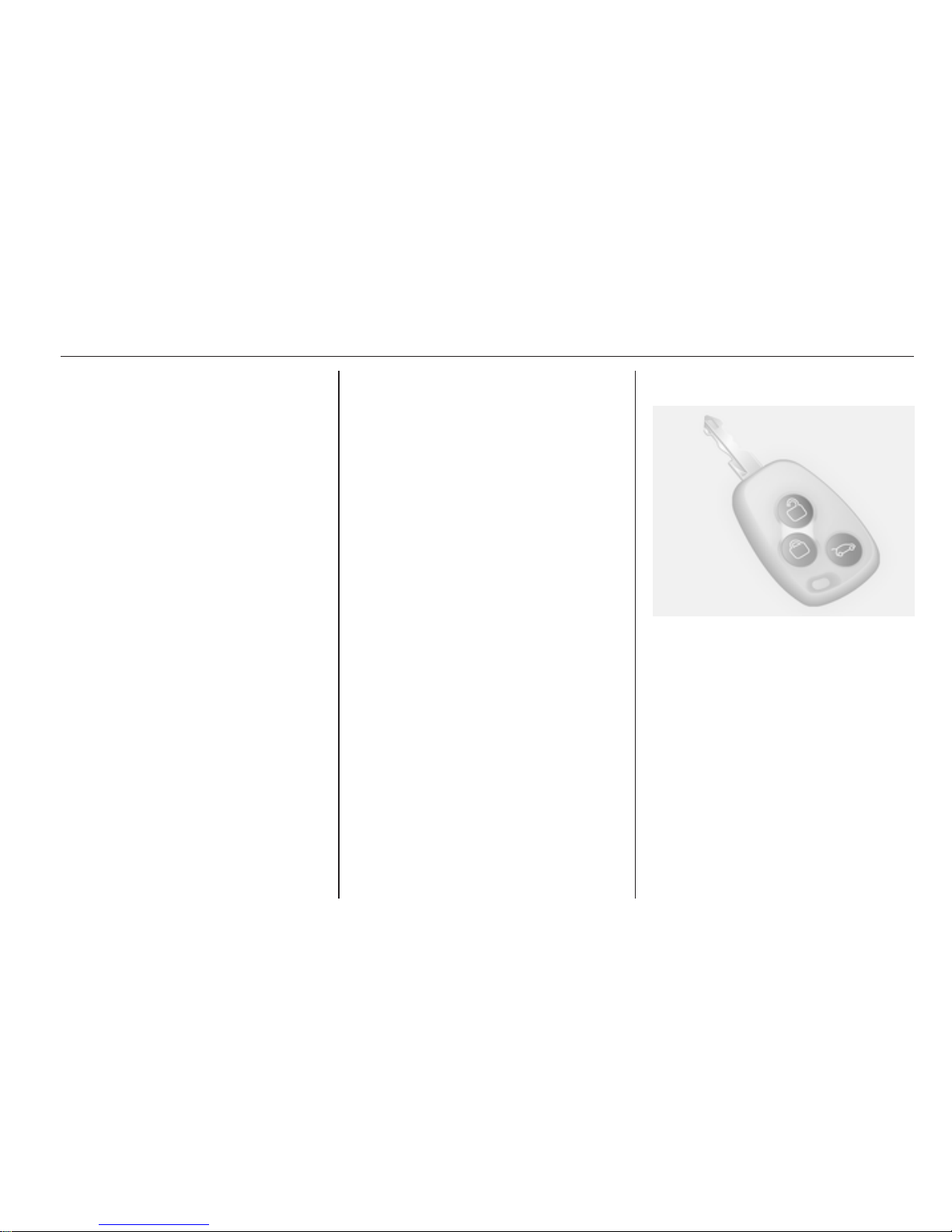
Radio remote control
Used to operate:
■ Central locking system
■ Anti-theft locking system
■ Anti-theft alarm system
The radio remote control has an
approximate range of up to 5 metres.
It can be affected by external
influences. The hazard warning
flashers confirm operation.
Handle with care, protect it from
moisture and high temperatures and
avoid unnecessary operation.
Page 18
18 Keys, doors and windows
Fault
If the central locking system cannot
be operated with the radio remote
control, it may be due to the following:
■ Range exceeded.
■ Battery voltage too low.
■ Frequent, repeated operation of the
radio remote control while not in
range, which will require
reprogramming by a workshop.
■ Interference from higher-power
radio waves from other sources.
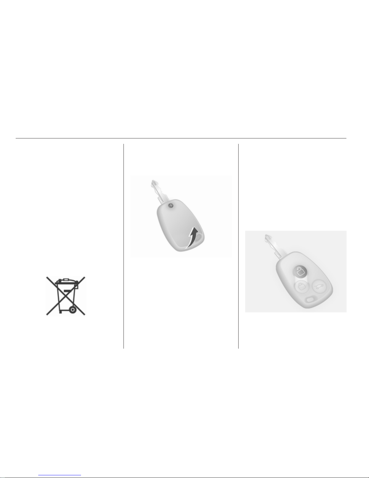
Radio remote control battery
replacement
Replace the battery as soon as the
range reduces.
Batteries do not belong in household
waste. They must be disposed of at
an appropriate recycling collection
point.
Remove screw and open battery
compartment by inserting a coin into
the slot and twisting.
Replace the battery (battery type
CR2016), paying attention to the
installation position.
Reattach both halves of cover
ensuring it engages correctly.
Replace screw and tighten.
Central locking system
Unlocks and locks doors and load
compartment.
With selective door locking, the
passenger compartment and load
compartment can be unlocked and
locked separately.
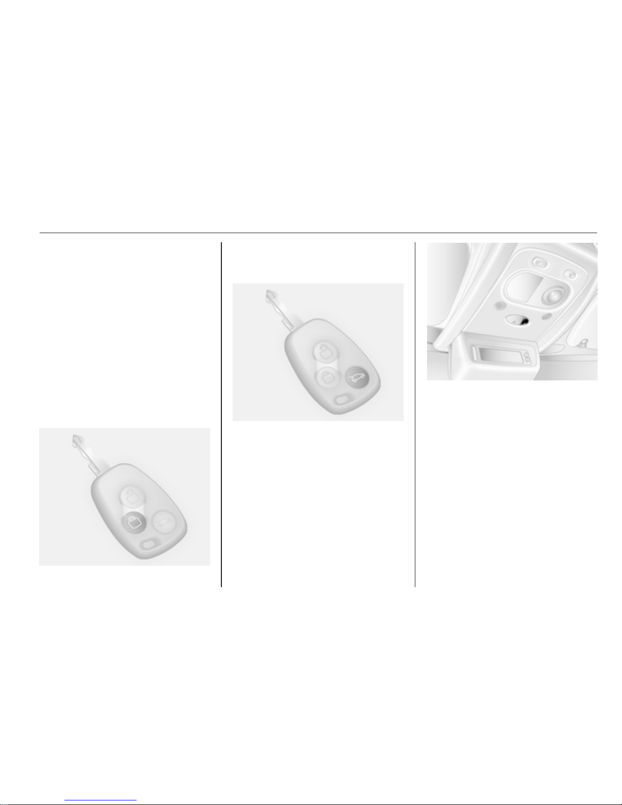
Unlocking
Press button c once to unlock all
doors and load compartment.
Page 19
Keys, doors and windows 19
Selective door locking
On vehicles with selective door
locking press button c once to unlock
the driver's door. To unlock all doors
and load compartment, press button
c again.
If no door is opened within approx.
2 minutes after the vehicle has been
unlocked with the remote control, the
vehicle is re-locked automatically.
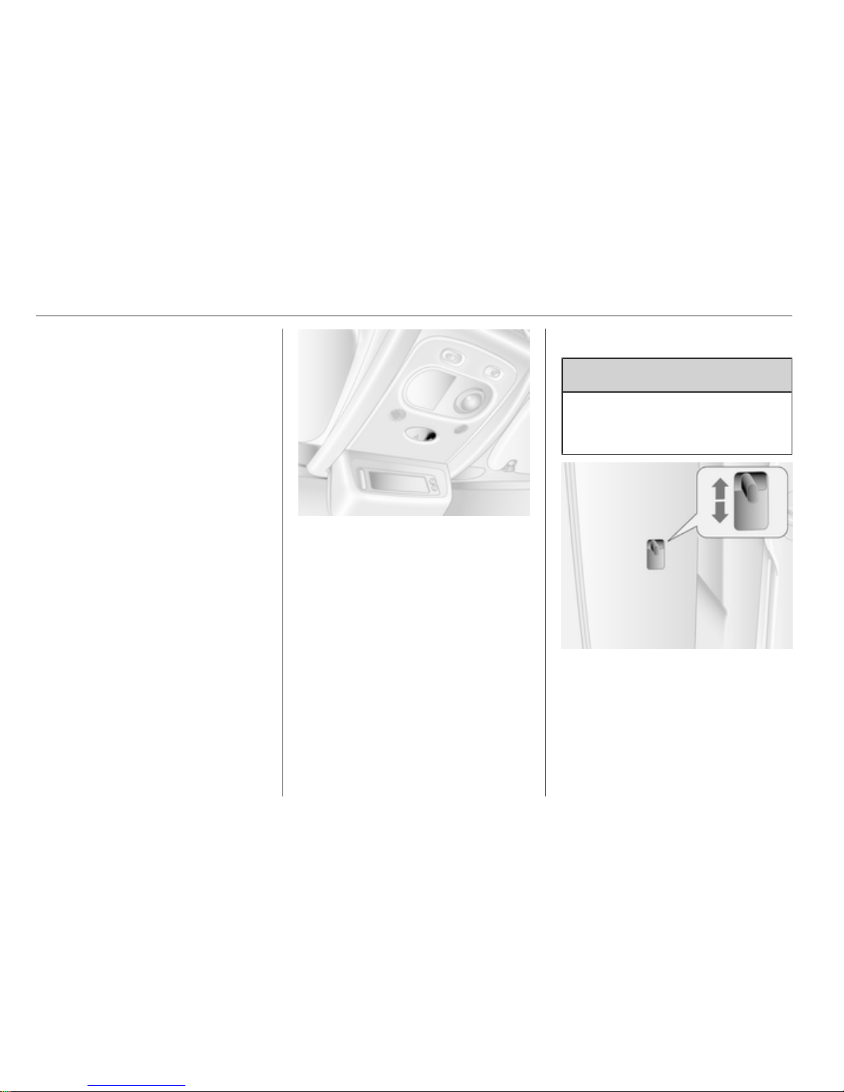
Locking
Close doors and load compartment. If
the doors are not closed properly, the
central locking system will not work.
Press button e.
All doors are locked.
Load compartment
With selective door locking the load
compartment can be locked and
unlocked independently. The front
doors remain locked.
Press button G.
Central locking button
Locks or unlocks all doors and the
load compartment from inside the
vehicle.
Press button e to lock or unlock all the
doors.
Fault in radio remote control
system
Unlocking
Manually unlock the driver's door by
turning the key in the lock. Switch on
the ignition and press the central
locking button e to open all doors and
load compartment.
Locking
Manually lock the driver's door by
turning the key in the lock.
Page 20
20 Keys, doors and windows
Fault in central locking system
Unlocking
Manually unlock the door by turning
the key in the lock. The other doors
can be opened by pulling the interior
handle.
Locking
Push inside locking knob of all doors
except driver's door. Then close the
driver's door and lock it from the
outside with the key.
Automatic locking
This security feature can be
configured to automatically lock all
doors and load compartment as soon
as the vehicle is driven.
To activate:
With the ignition switched on, press
e and hold for approx. 5 seconds until
an audible confirmation is heard.
To deactivate:
With the ignition switched on, press
e and hold for approx. 5 seconds until
an audible confirmation is heard.
Child locks
9 Warning
Use the child locks whenever
children are occupying the rear
seats.
Press down the child lock, door
cannot be opened from the inside.
Raise to deactivate.
Page 21
Keys, doors and windows 21
Doors
Sliding door
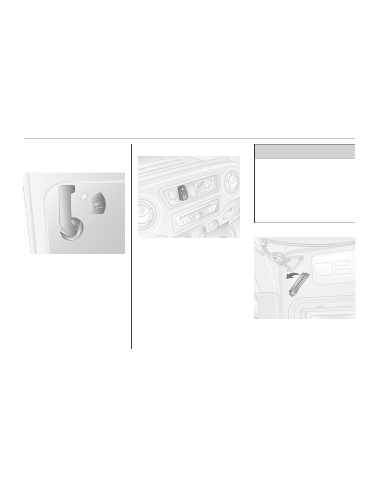
The door can be locked from inside
the vehicle with the interior lock
switch.
Power sliding door
With the parking brake applied, press
switch on the instrument panel to
open automatically. The warning
lamp illuminates on the instrument
panel.
Press switch again, the warning lamp
extinguishes and a chime sounds
when the power sliding door is
closing.
9 Warning
Take care when operating the
power sliding door. Risk of injury,
particularly to children.
Keep a close watch on the moving
door when operating. Ensure that
nothing becomes trapped during
operation and no one is standing
within the moving area.
Emergency exit
In an emergency, release the interior
handle and slide door back to open it.
Page 22
22 Keys, doors and windows
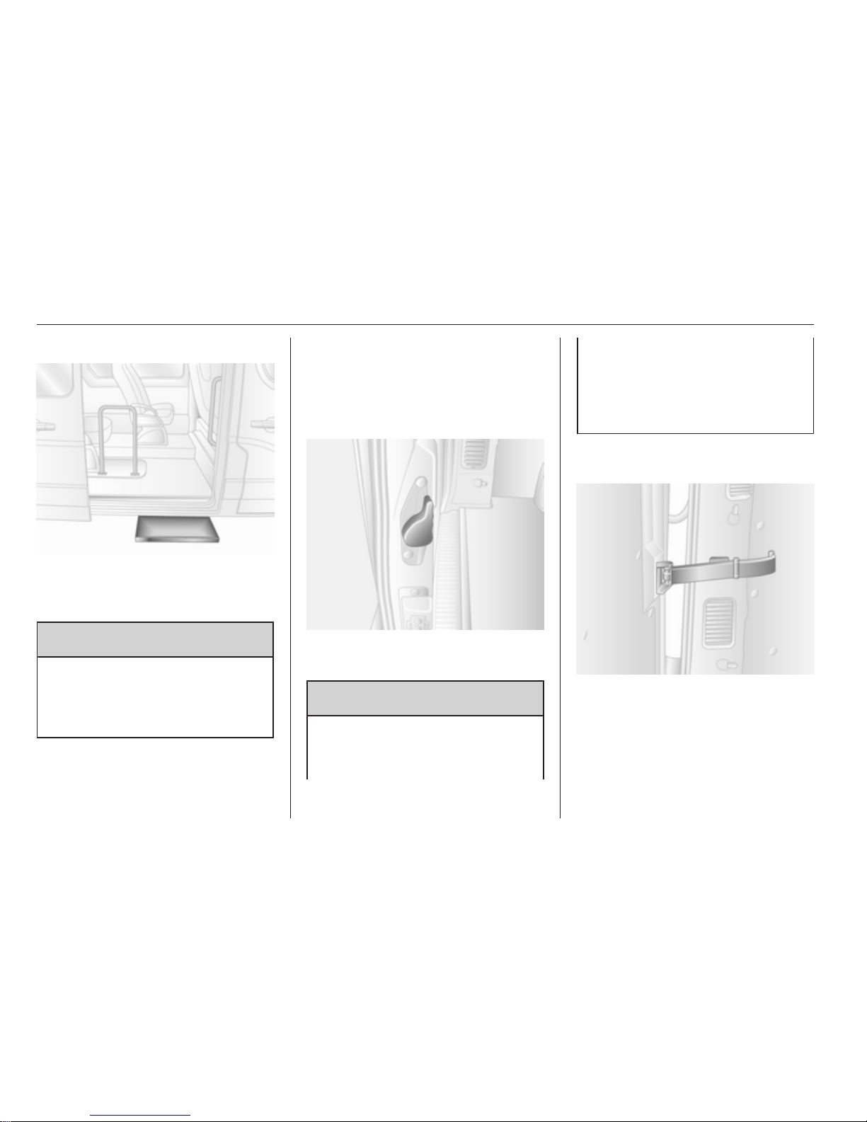
Power side step
The power side step operates
automatically when the sliding door is
opened or closed.
9 Warning
Ensure there is adequate
clearance to allow the power side
step to fully extend and retract
without obstruction.
Rear doors
To open the right hand rear door pull
the outside handle. The door is
opened from inside the vehicle by
pulling the interior handle.
The left hand rear door is released
using the lever.
9 Warning
The rear lights may be obscured if
the rear doors are open and the
vehicle is parked on the roadside.
Make other road users aware of
the vehicle, by using a warning
triangle or other equipment
specified in the road traffic
regulations.
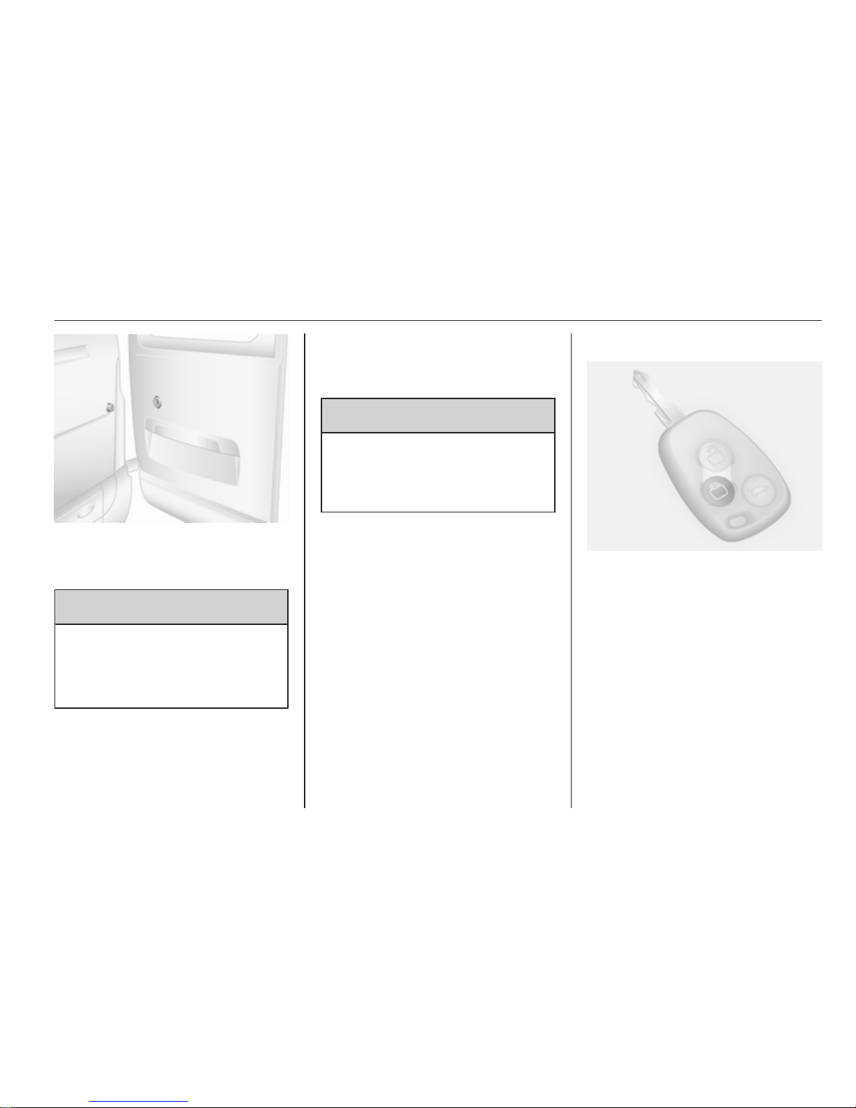
The doors are retained in the 90º
position by locking stays.
To open the doors to 180º, release
locking stays from the catches on the
door frames.
Page 23
Keys, doors and windows 23
When opening the doors to 270º, the
doors are retained in the fully open
position by magnets on the body side.
9 Warning
Ensure extended opening doors
are secured when fully opened.
Opened doors may slam closed
due to the force of the wind!
When closing the doors, secure each
locking stay to the catch on the door
frame.
Close the left hand door before the
right hand door.
Vehicle security
Anti-theft locking system
9 Warning
Do not use the system if there are
people in the vehicle! The doors
cannot be unlocked from the
inside.
The system deadlocks the doors. All
doors must be closed or the system
cannot be activated.
Unlocking the vehicle disables the
mechanical anti-theft locking system.
Unlocking is not possible with the
central locking button.
When the hazard warning flashers or
sidelights are switched on, the
system cannot be activated.
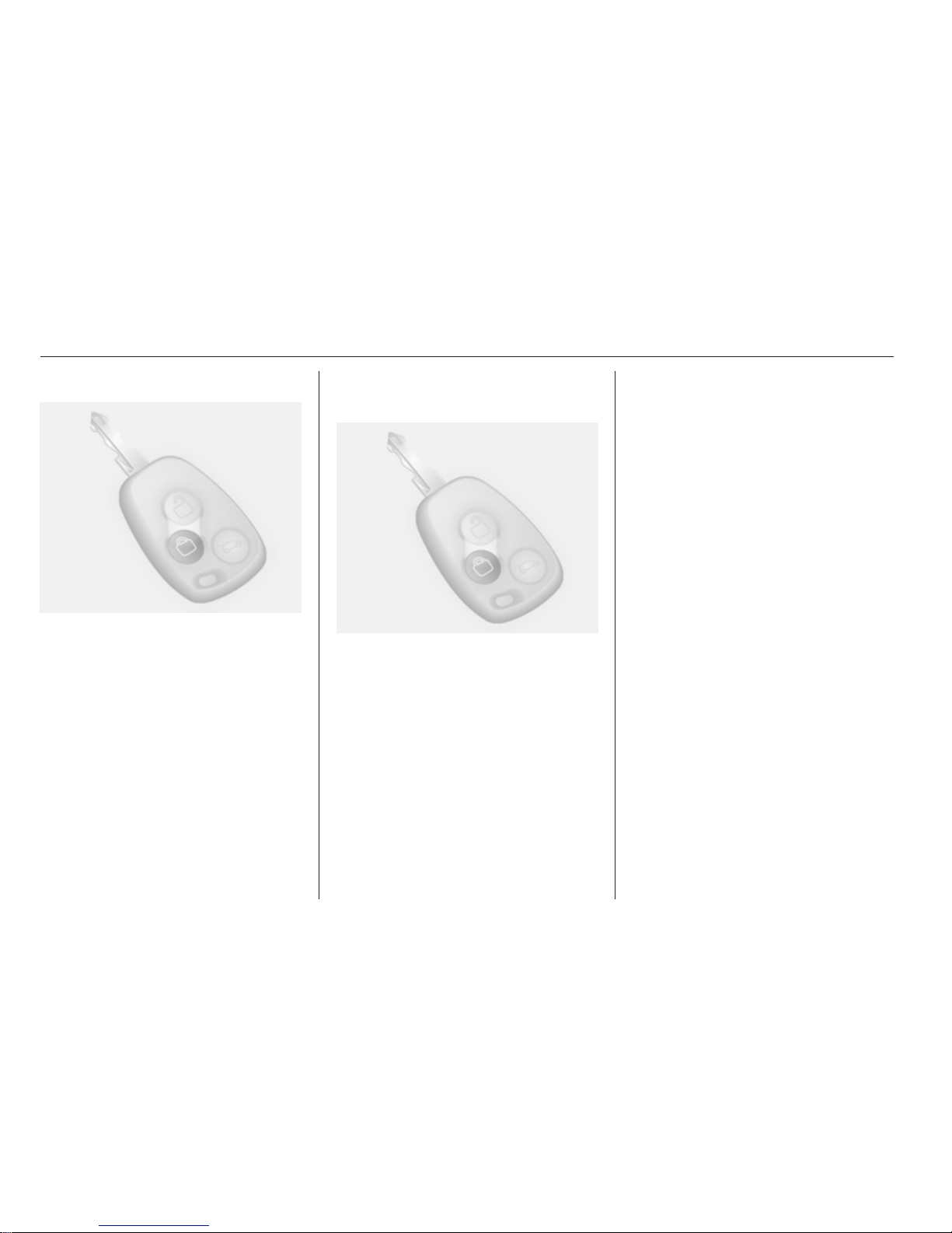
Activating
Press e on the radio remote control
twice within 10 seconds.
Anti-theft alarm system
The anti-theft alarm system is
operated in conjunction with the
central locking system.
It monitors:
■ Doors, load compartment, bonnet
■ Passenger compartment
■ Interruption of alarm siren power
supply
Page 24
24 Keys, doors and windows
Activation
All doors and the bonnet must be
closed.
Press button e.
If the hazard warning flashers do not
flash upon activation, a door or the
bonnet is not fully closed.
Activation without monitoring of
passenger compartment
Switch off monitoring of the
passenger compartment when
people or animals are being left in the
vehicle:
Press and hold button e. An audible
beep will sound to confirm that the
function has been disabled.
The status will remain until the antitheft alarm system is deactivated or
the doors are unlocked.
Deactivation
Unlocking the vehicle deactivates the
anti-theft alarm system. Turn signal
lights flash once upon deactivation.
When unlocking the vehicle using the
key, the alarm siren will sound. To
stop the siren, switch on the ignition.
Alarm
When triggered, the alarm sounds via
a separate battery-backed power
sounder, and the hazard warning
lights flash simultaneously. The
number and duration of alarm signals
are stipulated by legislation.
In the event of its power supply being
disconnected or disconnection of the
vehicle battery, the alarm siren will
sound. If vehicle battery is to be
disconnected, first deactivate the
anti-theft alarm system. To silence
the alarm siren if activated, reconnect
vehicle battery and unlock vehicle
with radio remote control.
The siren is silenced and the anti-theft
alarm system is deactivated by
pressing button c or by switching on
the ignition.
Page 25
Keys, doors and windows 25
Immobiliser
The system is part of the ignition
switch and checks whether the
vehicle is allowed to be started with
the key being used.
The electronic immobiliser activates
automatically after the key has been
removed from the ignition switch. It
also activates if the key is left in the
ignition switch when the engine has
been turned off.
Note
The immobiliser does not lock the
doors. Always lock the vehicle after
leaving it 3 18.
Exterior mirrors
Convex shape
The convex exterior mirror reduces
blind spots. The shape of the mirror
makes objects appear smaller, which
will affect the ability to estimate
distances.
Manual adjustment
Adjust mirrors by swivelling in
required direction.
The lower mirrors are not adjustable.
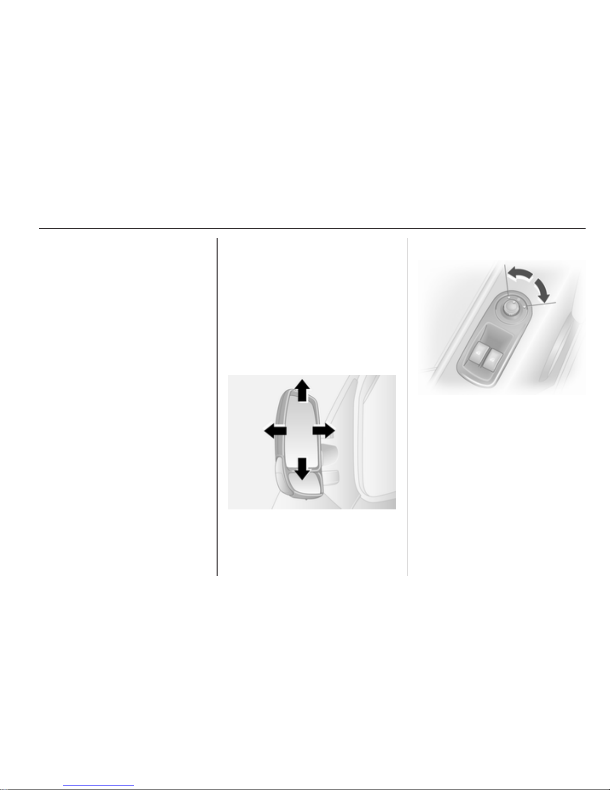
Electric adjustment
Select the relevant exterior mirror by
turning the control to left or right. Then
swivel the control to adjust the mirror.
In the central position no mirror is
selected.
The lower mirrors are not adjustable.
Page 26
26 Keys, doors and windows
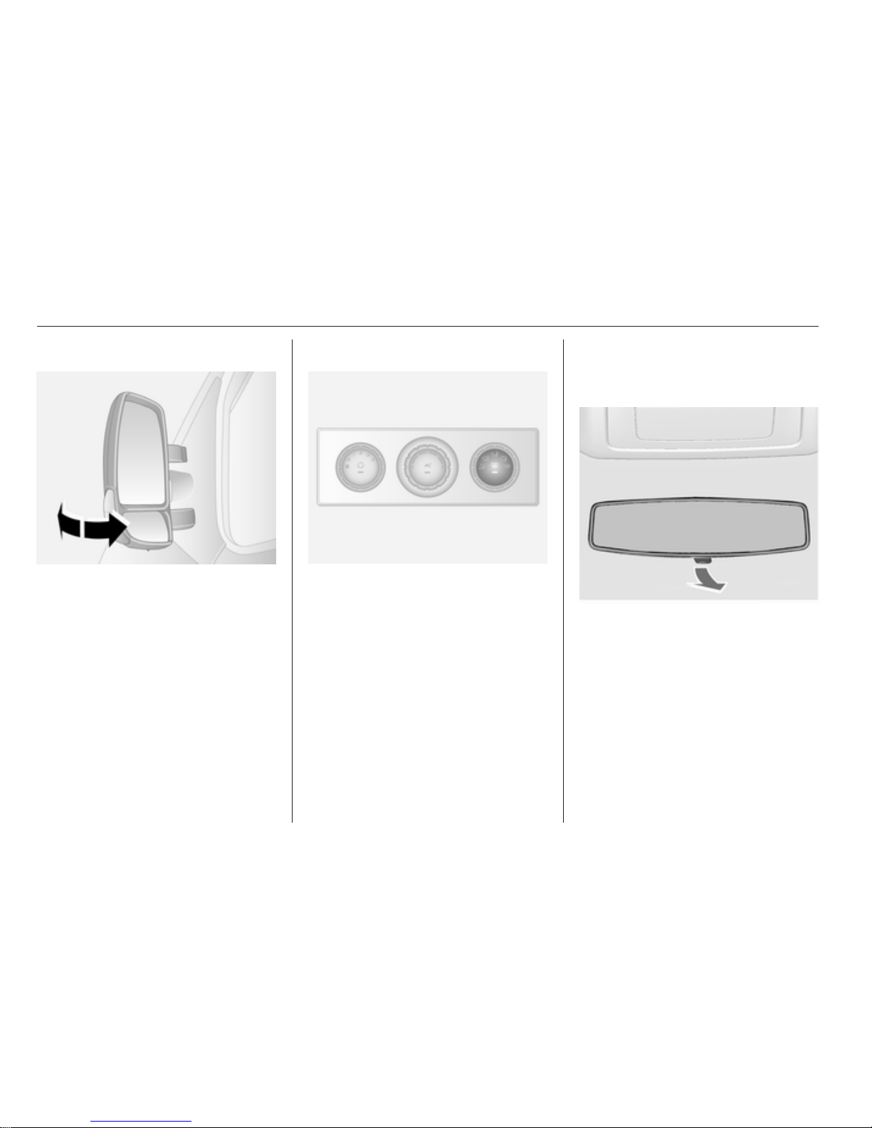
Folding
For pedestrian safety, the exterior
mirrors will swing out of their normal
mounting position if they are struck
with sufficient force. Reposition the
mirror by applying slight pressure to
the mirror housing.
Heated
Operated by pressing the Ü button.
Heating works with the engine
running and is switched off
automatically after a short time.
Electronic climate control system
3 84.
Interior mirrors
Manual anti-dazzle
To reduce dazzle, adjust the lever on
the underside of the mirror housing.
Page 27
Keys, doors and windows 27
Windows
Manual windows
The door windows can be opened or
closed with the window winders.
Power windows
9 Warning
Take care when operating the
power windows. Risk of injury,
particularly to children.
Keep a close watch on the
windows when closing them.
Ensure that nothing becomes
trapped in them as they move.
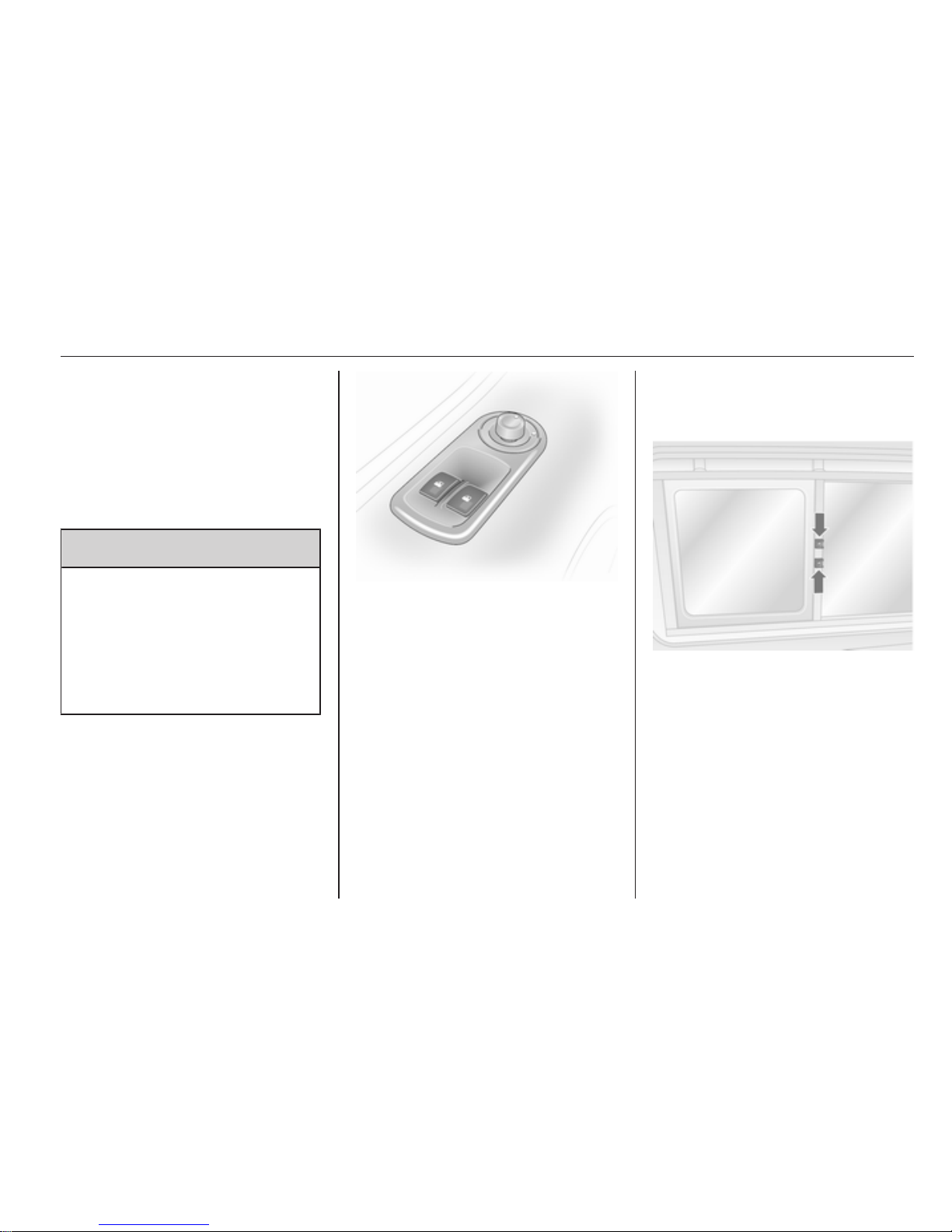
Switch on ignition to operate power
windows.
Operate the switch for the respective
window by pushing to open or pulling
to close.
For vehicles with automatic feature
on the driver's door window; when
opening pull or press the switch again
to stop window movement.
In the event of closing difficulties due
to frost or the like, operate the switch
several times to close the window in
stages.
Rear windows
Sliding side windows
Press catch and slide window to
open. Ensure catch engages when
closing.
Page 28
28 Keys, doors and windows
Press catch and slide window to
open. Ensure catch engages when
closing.
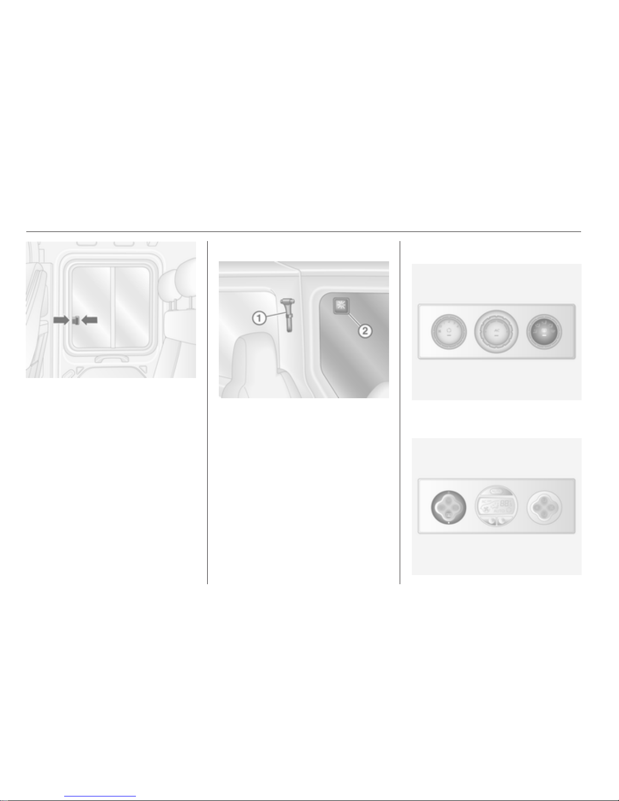
Emergency exit
To provide an emergency exit from
the vehicle, use hammer 1 to strike
glass 2.
Heated rear window
Operated by pressing the Ü button
on either system.
Page 29
Keys, doors and windows 29
Heating works with the engine
running and is switched off
automatically after a short time.
Sun visors
The sun visors can be folded down or
swivelled to the side to prevent
dazzling.
If the sun visors have integral mirrors,
the mirror covers should be closed
when driving.
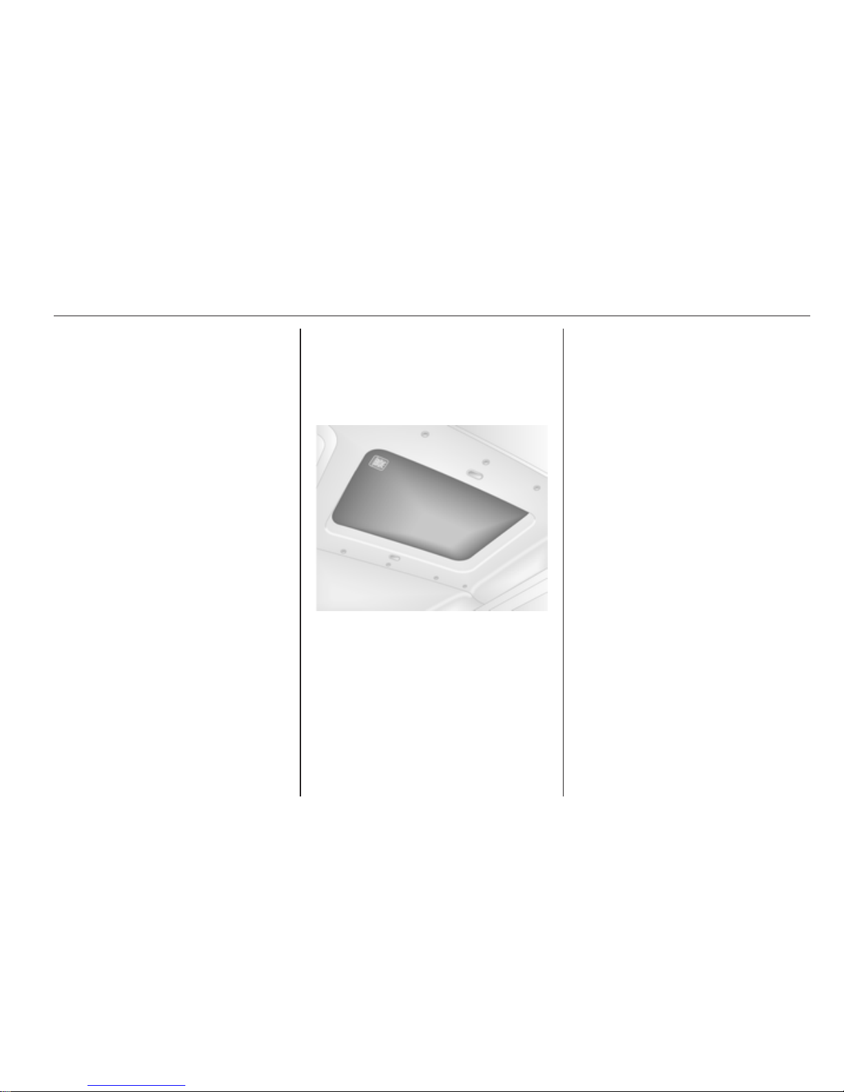
Roof
Glass panel
Emergency exit
In an emergency, the glass can be
broken. Use the hammer to break the
glass panel 3 27.
Page 30
30 Seats, restraints
Seats, restraints
Head restraints ............................ 30
Front seats ................................... 31
Rear seats ................................... 35
Seat belts ..................................... 37
Airbag system .............................. 40
Child restraints ............................. 43
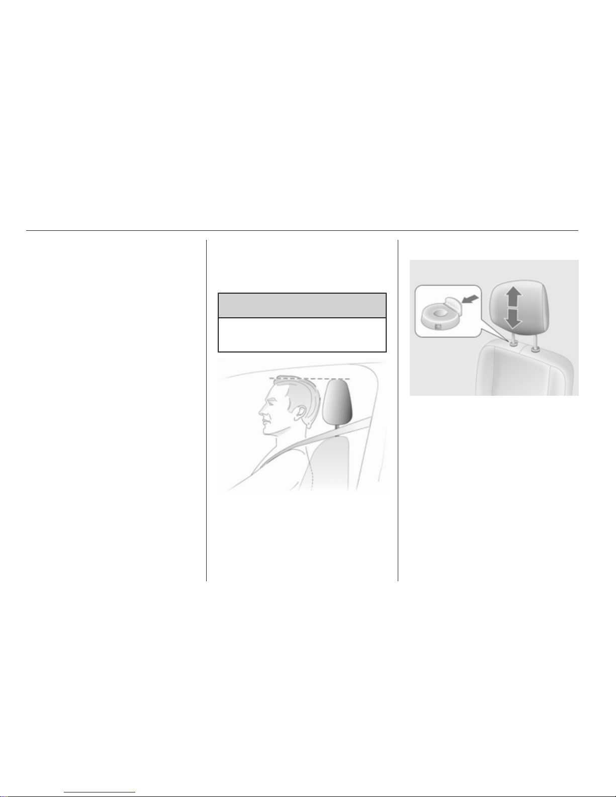
Head restraints
Position
9 Warning
Only drive with the head restraint
set to the proper position.
The upper edge of the head restraint
should be at upper head level. If this
is not possible for extremely tall
people, set to highest position, and
set to lowest position for small people.
Height adjustment
Press the catch, adjust height and
engage.
Note
Approved accessories may only be
attached to the front passenger seat
head restraint if the seat is not in use.
Page 31
Seats, restraints 31
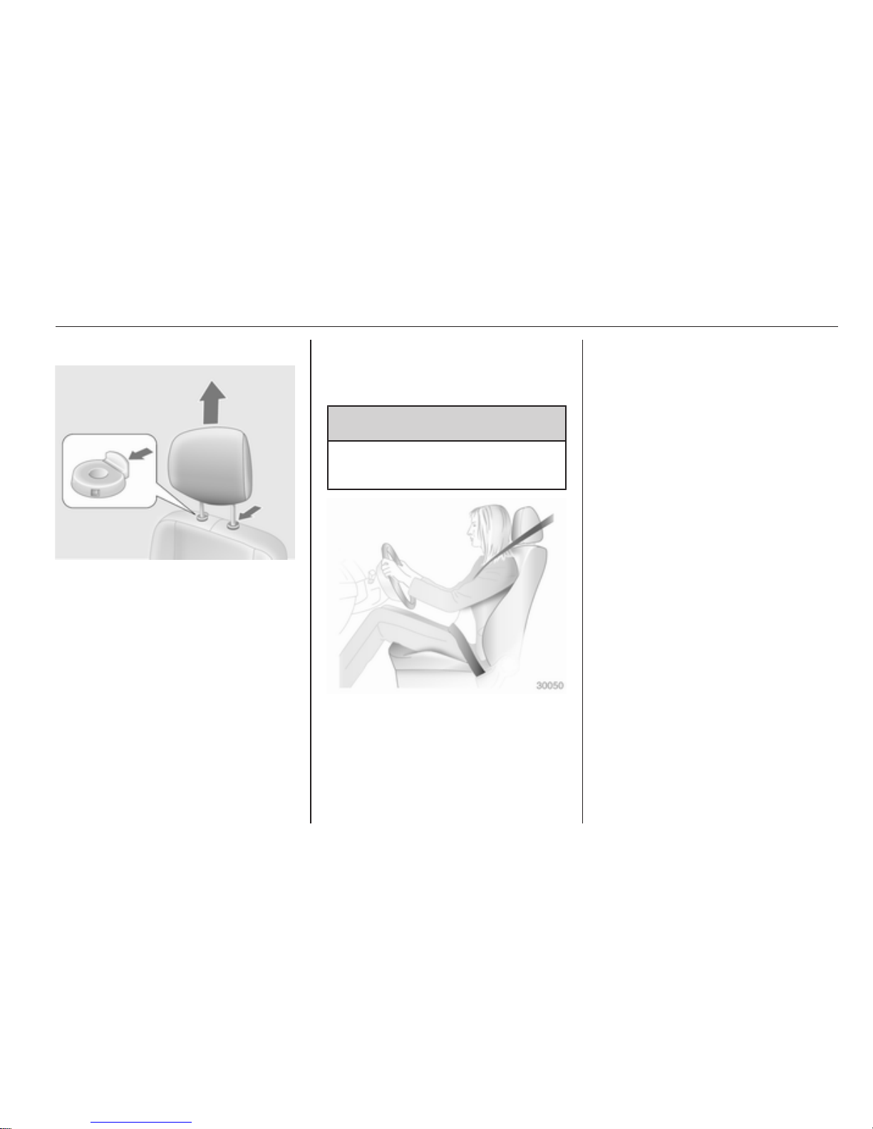
Removal
Press both catches, pull the head
restraint upwards and remove.
Front seats
Seat position
9 Warning
Only drive with the seat correctly
adjusted.
■
Sit with buttocks as far back against
the backrest as possible. Adjust the
distance between the seat and the
pedals so that legs are slightly
angled when pressing the pedals.
Slide the front passenger seat as
far back as possible.
■ Sit with shoulders as far back
against the backrest as possible.
Set the backrest rake so that it is
possible to reach the steering
wheel with arms slightly bent.
Maintain contact between
shoulders and the backrest when
turning the steering wheel. Do not
angle the backrest too far back. We
recommend a maximum rake of
approx. 25°.
■ Adjust the steering wheel 3 59.
■ Set seat height high enough to
have a clear field of vision on all
sides and of all display instruments.
There should be at least one hand
of clearance between head and the
roof frame. Thighs should rest
lightly on the seat without pressing
into it.
■ Adjust the head restraint 3 30.
■ Adjust the height of the seat belt
3 38.
■ Adjust the lumbar support so that it
supports the natural shape of the
spine.
Page 32
32 Seats, restraints
Seat adjustment
9 Danger
Do not sit nearer than 25 cm from
the steering wheel, to permit safe
airbag deployment.
9 Warning
Never adjust seats while driving as
they could move uncontrollably.
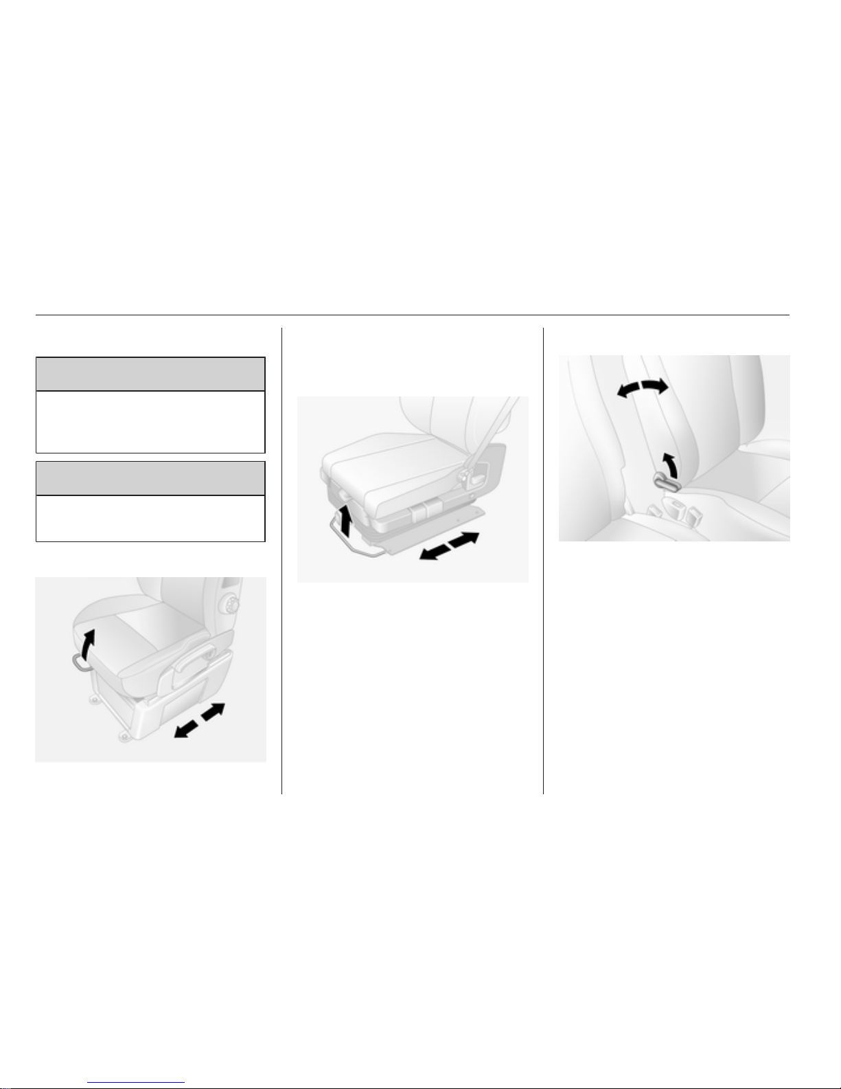
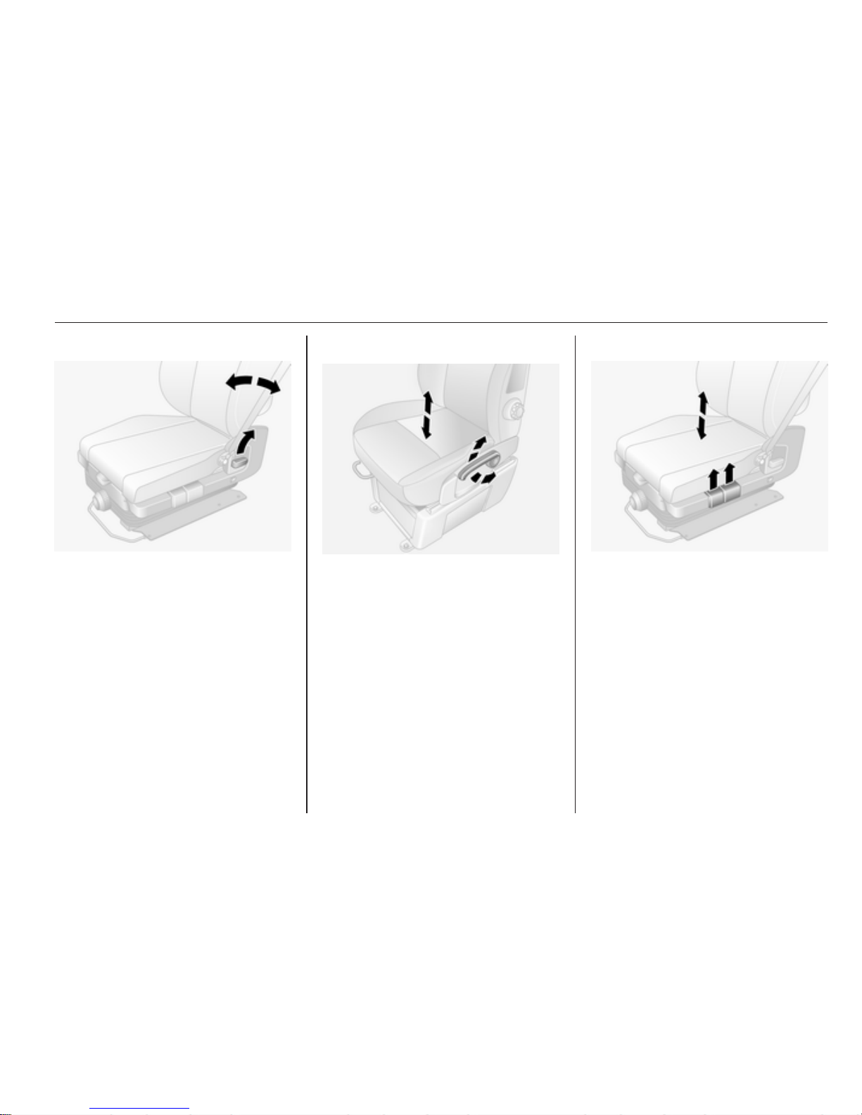
Seat positioning
Pull handle, slide seat, release
handle.
Suspension seat positioning
Pull handle, slide seat, release
handle.
Seat backrests
Pull lever, adjust inclination and
release lever. Allow the seat to
engage.
Page 33
Seats, restraints 33
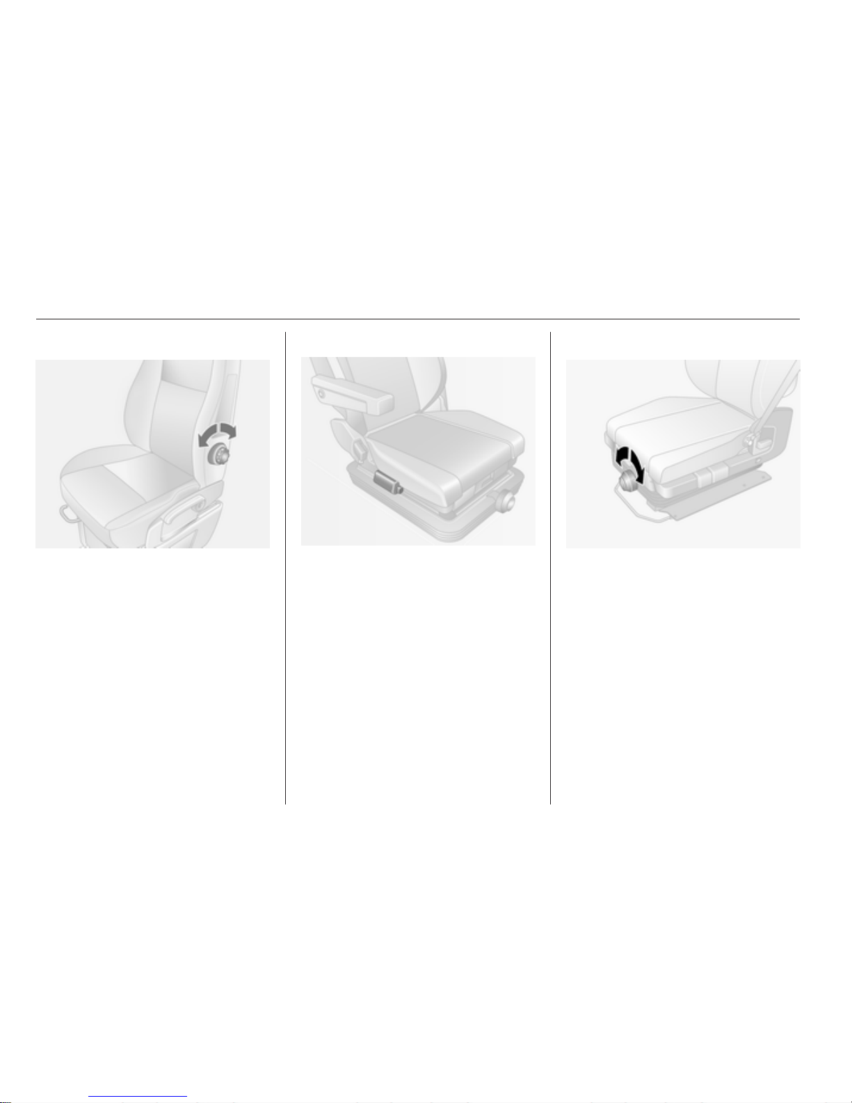
Suspension seat backrests
Pull lever, adjust inclination and
release lever. Allow the seat to
engage.
Seat height
Lever motion
up = seat higher
down = seat lower
Suspension seat height
Pull forward lever up to adjust the
front of the seat and rear lever to
adjust the rear of the seat.
Page 34
34 Seats, restraints
Lumbar support
Adjust lumbar support by turning the
handwheel while relieving the load on
the backrest.
Suspension seat lumbar support
Adjust lumbar support by activating
bulb or releasing button.
Suspension seat sensitivity
To adjust the level of sensitivity rotate
knob.
Page 35
Seats, restraints 35
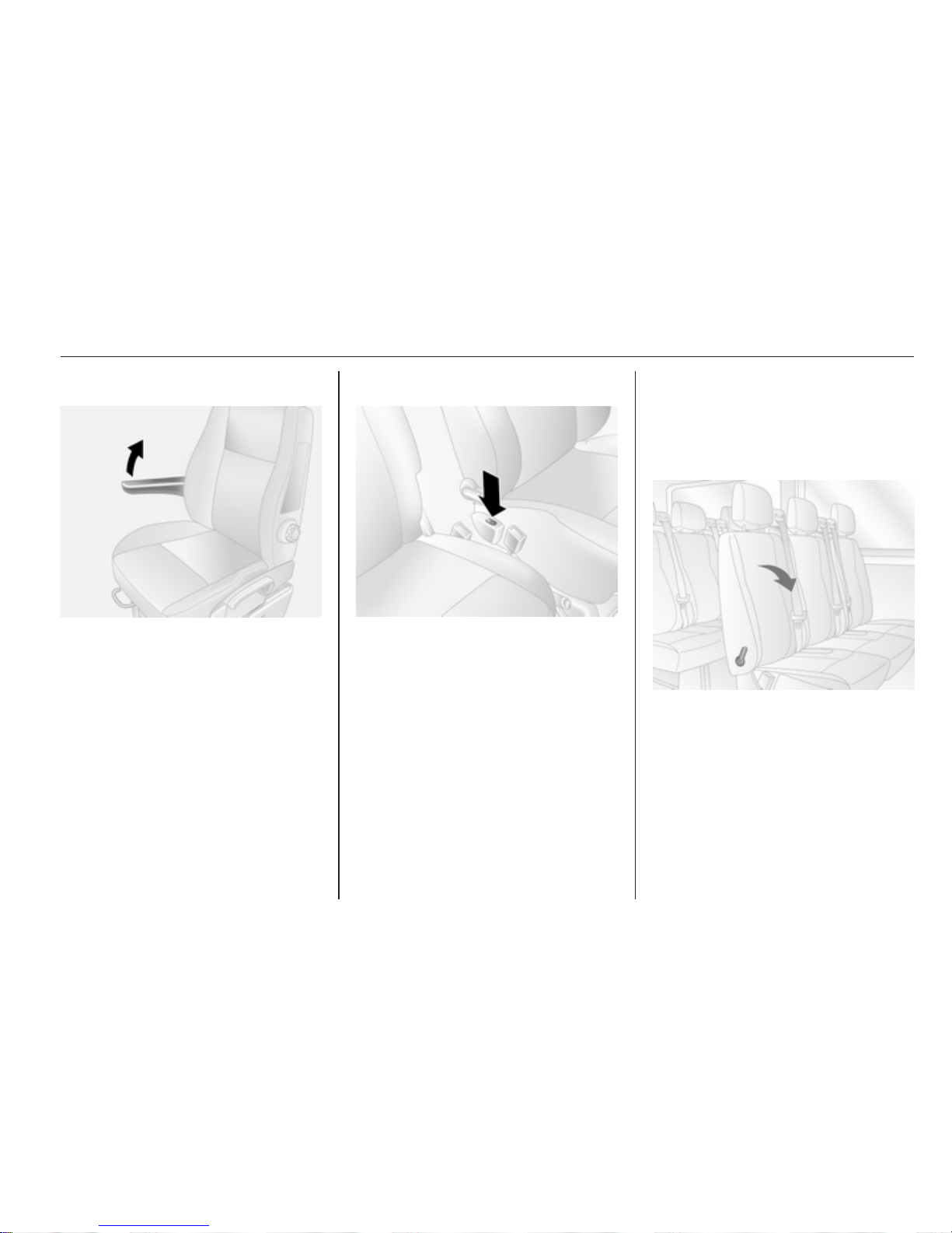
Armrest
Armrest can be folded up when not
required.
Heating
Press the ß button for the respective
seat with the engine running. Press
the ß button again to switch off.
Seat heating is thermostatically
controlled and switches off
automatically when seat temperature
is sufficient.
Control indicator in the button
illuminates when the system is on, not
just when heating is active.
Rear seats
Second row seats
Rear seat access
To facilitate access to the rear seats,
pull release lever and fold the seat
backrest forwards.
Page 36
36 Seats, restraints
9 Warning
Ensure that the backrest returns to
its correct position and the seat
belt buckles engage securely.
Fitting seat belt 3 38.
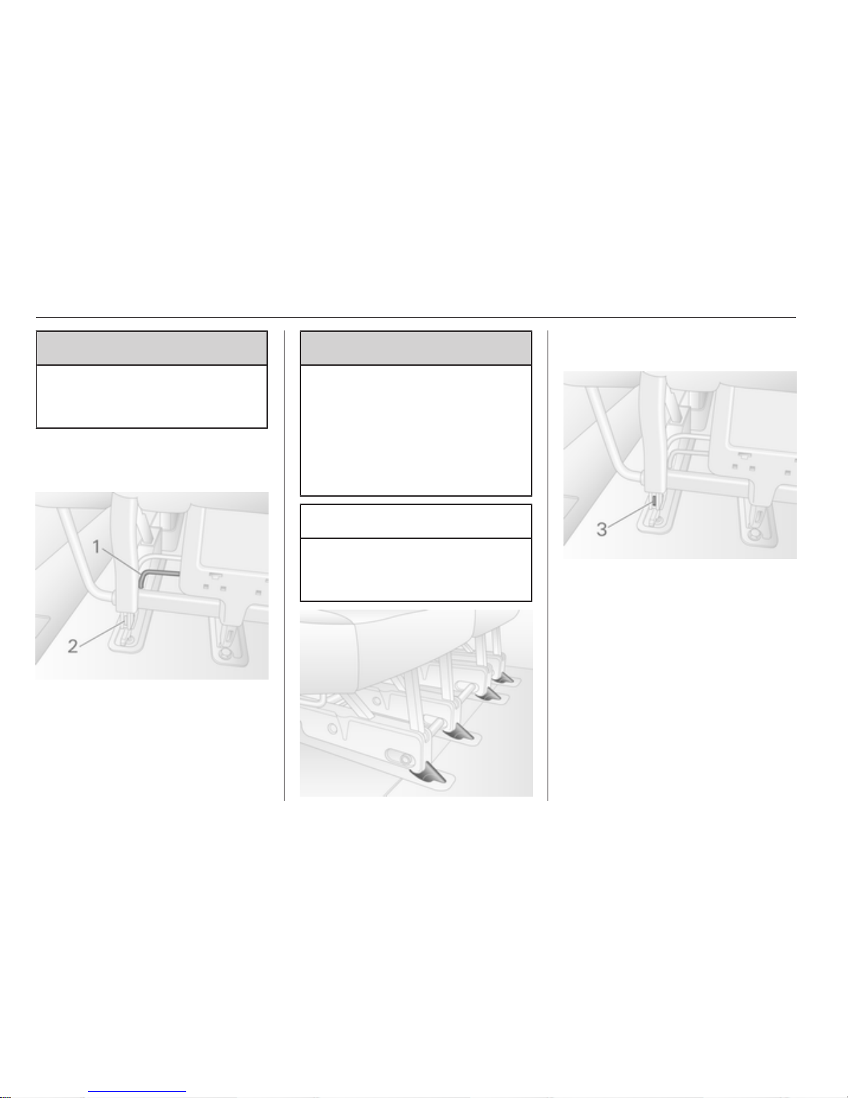
Removable rear seats
To remove: raise lever 1 on both sides
of the seat. Pins 2 appear to indicate
the seat is unlocked. Move the seat
towards the rear and release from the
floor anchor points. The seat can then
be lifted out.
9 Warning
Removable seats are heavy! Do
not attempt to remove without
assistance.
When installing the seats, ensure
that the seats are properly located
on the anchor points and that the
locking catches are fully engaged.
Caution
The rear seats are not
interchangeable and must be fitted
back into their original position.
To replace: position the seat on the
front anchor points and slide forward.
The seat locks automatically and pins
3 will no longer be visible.
Page 37
Seats, restraints 37
Seat belts
The seat belts are locked during
heavy acceleration or deceleration of
the vehicle holding the occupants in
the sitting position. Thereby the risk of
injury is considerably reduced.
9 Warning
Fasten seat belt before each trip.
In the event of an accident, people
not wearing seat belts endanger
their fellow occupants and
themselves.
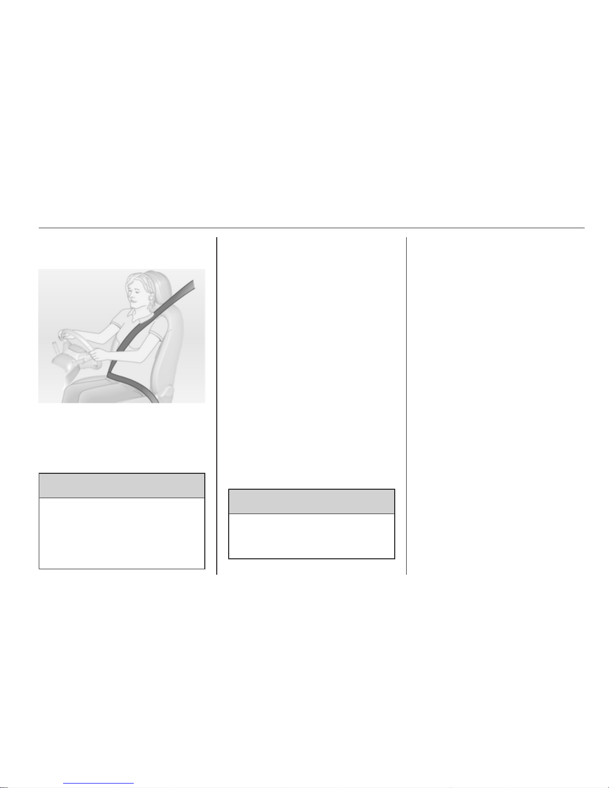
Seat belts are only designed to be
used by only one person at a time.
They are not suitable for people
smaller than 150 cm.
Periodically check all parts of the belt
system for damage and proper
functionality.
Have damaged components
replaced. After an accident, have the
belts and triggered belt pretensioners
replaced by a workshop.
Note
Make sure that the belts are not
damaged by shoes or sharp-edged
objects or trapped. Prevent dirt from
getting into the belt retractors.
Belt pretensioners
In the event of a head-on or rear-end
collision of a certain severity, the front
seat belts are tightened.
9 Warning
Incorrect handling (e.g. removal or
fitting of belts) can trigger the belt
pretensioners.
Deployment of the belt pretensioners
is indicated by continuous illumination
of control indicator v 3 69.
Triggered belt pretensioners must be
replaced by a workshop. Belt
pretensioners can only be triggered
once.
Note
Do not affix or install accessories or
other objects that may interfere with
the operation of the belt
pretensioners. Do not make any
modifications to belt pretensioner
components as this will invalidate
the vehicle type approval.
Page 38
38 Seats, restraints
Three-point seat belt
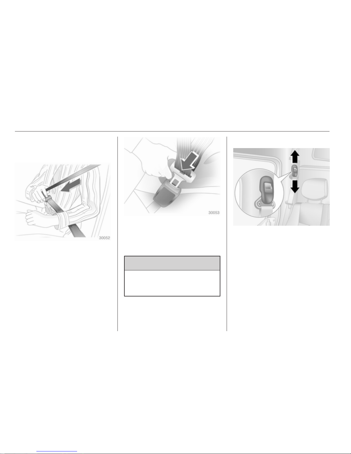
Fastening
Withdraw the belt from the retractor,
guide it untwisted across the body
and insert the latch plate into the
buckle. Tighten the lap belt regularly
whilst driving by pulling the shoulder
belt.
Loose or bulky clothing prevents the
belt from fitting snugly. Do not place
objects such as handbags or mobile
phones between the belt and your
body.
9 Warning
The belt must not rest against hard
or fragile objects in the pockets of
your clothing.
Height adjustment
1. Pull belt out slightly.
2. Press button.
3. Adjust height and engage.
Page 39
Seats, restraints 39
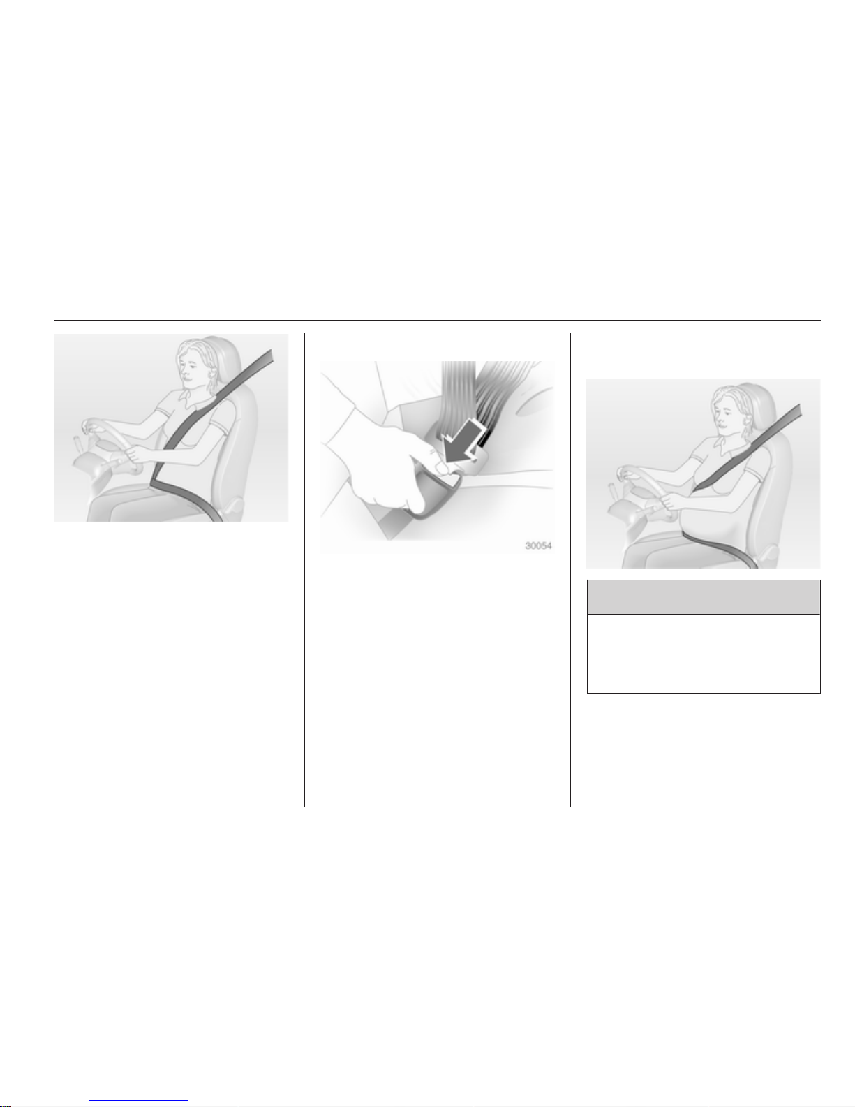
Adjust the height so that the belt lies
across the shoulder. It must not lie
across the throat or upper arm.
Do not adjust while driving.
Removing
To release belt, press red button on
belt buckle.
Using the seat belt while
pregnant
9 Warning
The lap belt must be positioned as
low as possible across the pelvis
to prevent pressure on the
abdomen.
Page 40
40 Seats, restraints
Airbag system
The airbag system consists of
a number of individual systems
depending on the scope of
equipment.
When triggered the airbags inflate
within milliseconds. They also deflate
so quickly that it is often unnoticeable
during the collision.
9 Warning
If handled improperly the airbag
systems can be triggered in an
explosive manner.
Note
The airbag systems and belt
pretensioner control electronics are
located in the centre console area.
Do not put any magnetic objects in
this area.
Do not stick anything on the airbag
covers and do not cover them with
other materials.
Each airbag is triggered only once.
Have deployed airbags replaced by
a workshop. Above that it might be
necessary to have the steering
wheel, the instrument panel, parts of
the panelling, the door seals,
handles and the seats replaced.
Do not make any modifications to
the airbag system as this will
invalidate the vehicle type approval.
Control indicator v for airbag systems
3 69.
Front airbag system
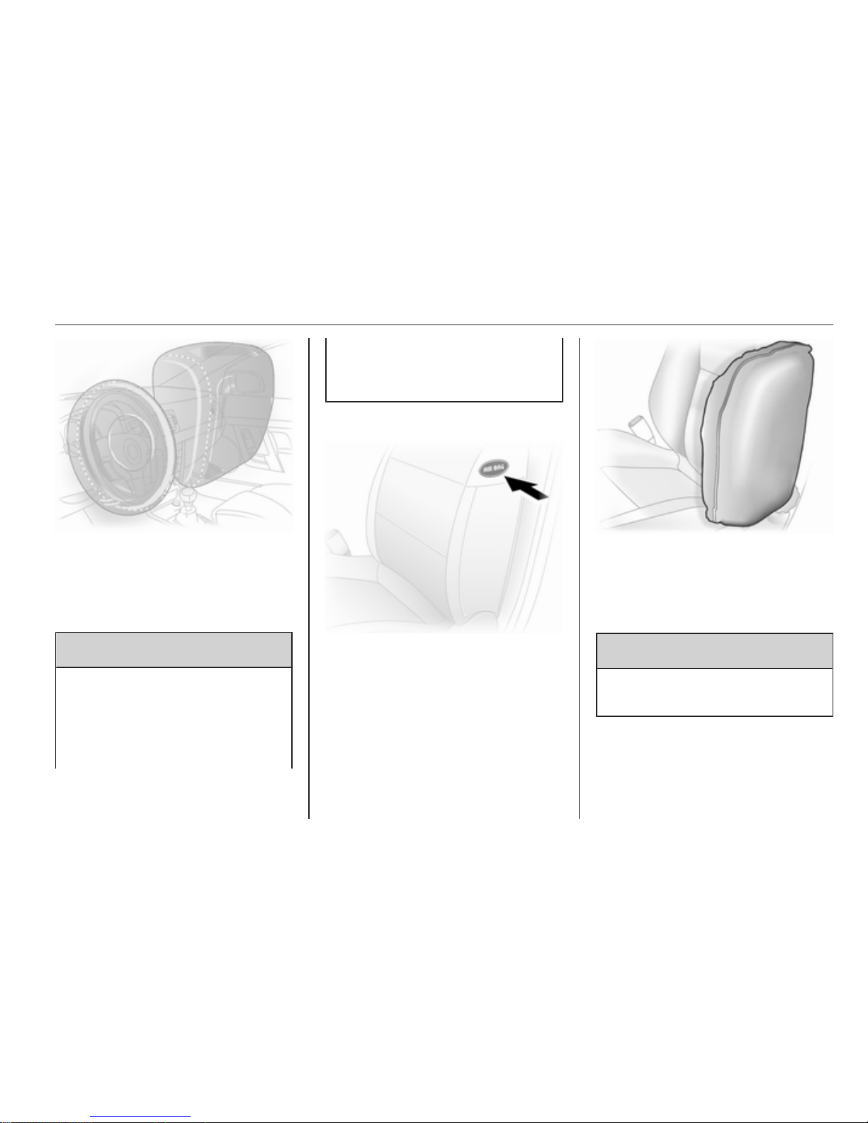
The front airbag system consists of
one airbag in the steering wheel and
one in the instrument panel on the
front passenger side. These can be
identified by the word AIRBAG.
There is also a warning label on the
side of the instrument panel, visible
when the front passenger door is
open.
The front airbag system is triggered in
the event of a front-end impact of
a certain severity. The ignition needs
to be switched on.
Page 41
Seats, restraints 41
The inflated airbags cushion the
impact, thereby considerably
reducing the risk of injury to the upper
body and head of the front seat
occupants.
9 Warning
Optimum protection is only
provided when the seat is in the
proper position 3 31.
Keep the area in which the airbag
inflates clear of obstructions.
Fit the seat belt correctly and
engage securely. Only then the
airbag is able to protect.
Side airbag system
The side airbag system consists of an
airbag in each front seat backrest.
This can be identified by the word
AIRBAG.
The side airbag system is triggered in
the event of a side impact of a certain
severity. The ignition needs to be
switched on.
The inflated airbags cushion the
impact, thereby reducing the risk of
injury to the upper body and pelvis in
the event of a side-on collision
considerably.
9 Warning
Keep the area in which the airbag
inflates clear of obstructions.
Note
Only use protective seat covers that
have been approved for the vehicle.
Be careful not to cover the airbags.
Page 42
42 Seats, restraints
Airbag deactivation
Front airbag and side airbag systems
for the front passenger seat have to
be deactivated if a child restraint
system is to be fitted on this seat. The
belt pretensioners and all driver
airbag systems will remain active.
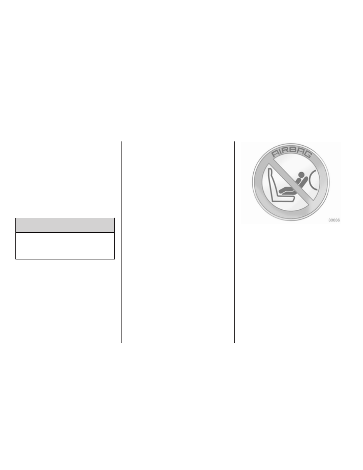
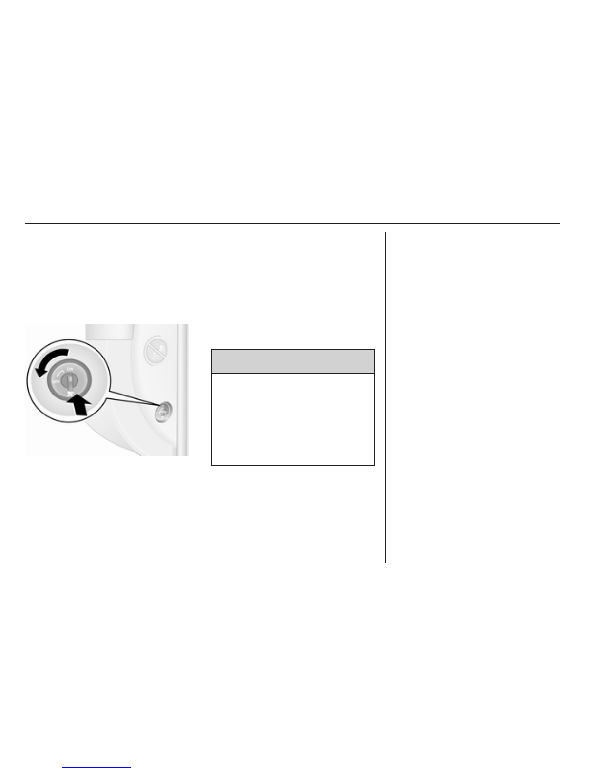
The front passenger airbag system
can be deactivated via a switch on the
side of the instrument panel.
With the front passenger door open,
press switch in and rotate anticlockwise to the OFF position.
Front passenger seat airbags are
deactivated and will not inflate in the
event of a collision. Control indicator
* illuminates continuously alongside
the information display or on the
instrument panel. A child restraint
system can be installed in
accordance with the installation
locations chart 3 44. An adult must
not occupy the front passenger seat.
9 Danger
Risk of fatal injury for a child using
a child restraint system together
with activated front passenger
airbag.
Risk of fatal injury for an adult
person with deactivated front
passenger airbag.
As long as control indicator * is not
illuminated, the airbag systems for
the front passenger seat will inflate in
the event of a collision.
If control indicator A remains
illuminated together with v, this
indicates a fault within the system.
Seek the assistance of a workshop.
Change status only when the vehicle
is stopped with the ignition off. Status
remains until the next change.
Control indicator for airbag
deactivation 3 69.
Page 43
Seats, restraints 43
Child restraints
Child restraint systems
We recommend the Opel child
restraint system which is tailored
specifically to the vehicle.
When a child restraint system is being
used, pay attention to the following
usage and installation instructions
and also those supplied with the child
restraint system.
Always comply with local or national
regulations. In some countries, the
use of child restraint systems is
forbidden on certain seats.
9 Warning
When using a child restraint
system on the front passenger
seat, the airbag systems for the
front passenger seat must be
deactivated; if not, the triggering of
the airbags poses a risk of fatal
injury to the child.
This is especially the case if rearfacing child restraint systems are
used on the front passenger seat.
Selecting the right system
Children should travel facing
rearwards in the vehicle as long as
possible. This makes sure that the
child's backbone, which is still very
weak, is under less strain in the event
of an accident.
Children under the age of 12 years
that are smaller than 150 cm are only
allowed to travel in a restraint system
that is suitable for the child. Suitable
are restraint systems that comply with
ECE 44-03 or ECE 44-04. Since
a proper position of the belt is rarely
possible with a child that is smaller
than 150 cm, we strongly advise to
use an appropriate child restraint
system, even though this might, due
to the age of the child, no longer be
legally binding.
Ensure that the child restraint system
to be installed is compatible with the
vehicle type.
Ensure that the mounting location of
the child restraint system within the
vehicle is correct.
Allow children to enter and exit the
vehicle only on the side facing away
from the traffic.
When the child restraint system is not
in use, secure the seat with a seat belt
or remove it from the vehicle.
Note
Do not stick anything on the child
restraint systems and do not cover
them with any other materials.
A child restraint system which has
been subjected to stress in an
accident must be replaced.
Page 44

44 Seats, restraints
Child restraint installation locations
Permissible options for fitting a child restraint system
Front seats - all variants
Weight and age class Single seat - front passenger
1)
Bench seat - front passenger
without airbag with airbag
without airbag with airbag
centre outer centre outer
Group 0: up to 10 kg
or approx. 10 months
Group 0+: up to 13 kg
or approx. 2 years
U
U
2)
U U
U
2)
U
2)
Group I: 9 to 18 kg
or approx. 8 months to 4 years
U
U
2)
U U
U
2)
U
2)
Group II: 15 to 25 kg
or approx. 3 to 7 years
Group III: 22 to 36 kg
or approx. 6 to 12 years
U
U
2)
U U
U
2)
U
2)
U = Suitable for universal category restraint systems for use in this mass group, in conjunction with three-point seat belt.
1)
If adjustable, ensure seat is in its rearmost position. Make sure vehicle seat belt is as straight as possible between
shoulder and upper anchorage point.
2)
Ensure the front passenger airbag system is deactivated when installing a child restraint in this position.
Page 45

Seats, restraints 45
Crew cab - rear seats
Weight and age class
2nd row bench seat
Outer Centre
Group 0: up to 10 kg
or approx. 10 months
Group 0+: up to 13 kg
or approx. 2 years
U X
Group I: 9 to 18 kg
or approx. 8 months to 4 years
U X
Group II: 15 to 25 kg
or approx. 3 to 7 years
Group III: 22 to 36 kg
or approx. 6 to 12 years
U X
U = Suitable for universal category restraint systems for use in this weight and age class, in conjunction with three-point
seat belt.
X = Seat position not suitable for children in this weight and age class.
Page 46

46 Seats, restraints
Combi - rear seats
Weight and age class
2nd row
bench seat
3rd row
bench seat
Behind driver
Behind front
passenger Centre
Group 0, 0+: up to 13 kg
or approx. 2 years
U3), <
X X X
Group I: 9 to 18 kg
or approx. 8 months to 4 years
U4), < UF
4)
UF4), <
X
Group II: 15 to 25 kg
or approx. 3 to 7 years
Group III: 22 to 36 kg
or approx. 6 to 12 years
U
4)
UF
4)
UF
4)
X
3)
Move the front seat as far forward as possible to install a rear facing child seat, then move back the seat in front in
accordance with the child seat instructions.
4)
Forward facing child seat; position the seatback of the child seat in contact with the seatback of the vehicle seat. Adjust
the height of the headrest or remove it if necessary; do not push the seat in front of the child more than halfway back
on its runners and do not recline the seatback more than 25°.
Page 47

Seats, restraints 47
U = Suitable for universal category restraint systems for use in this weight and age class, in conjunction with three-point
seat belt.
UF = Suitable for universal category forward-facing restraint systems for use in this weight and age class, in conjunction
with three-point seat belt.
<
= Seat with ISOFIX mounting available. When mounting an ISOFIX child restraint system, only systems that have
been approved for the vehicle may be used.
X = Seat position not suitable for children in this weight and age class.
Bus - rear seats
Weight and age class Rear seats
Group 0: up to 10 kg
or approx. 10 months
Group 0+: up to 13 kg
or approx. 2 years
X
Group I: 9 to 18 kg
or approx. 8 months to 4 years
X
Group II: 15 to 25 kg
or approx. 3 to 7 years
Group III: 22 to 36 kg
or approx. 6 to 12 years
X
X = Seat position not suitable for children in this weight and age class.
Page 48

48 Seats, restraints
Permissible options for fitting an ISOFIX child restraint system
Combi - rear seats
Weight class Size class Fixture
On front
passenger seat
On 2nd row
bench seats
On 3rd row
bench seats
Behind driver
Behind
front passenger Centre
Group 0: up to 10 kg E ISO/R1 X IL X X X
Group 0+: up to 13 kg E ISO/R1 X IL X X X
D ISO/R2 X IL X X X
C ISO/R3 X IL X X X
Group I: 9 to 18 kg D ISO/R2 X IL X X X
C ISO/R3 X IL X X X
B ISO/F2 X IL, IUF X IL, IUF X
B1 ISO/F2X X IL, IUF X IL, IUF X
A ISO/F3 X IL, IUF X IL, IUF X
IL = Suitable for particular ISOFIX restraint systems of the 'specific-vehicle', 'restricted' or 'semi-universal' categories.
The ISOFIX restraint system must be approved for the specific vehicle type.
IUF = Suitable for ISOFIX forward-facing child restraint systems of universal category approved for use in this weight class.
X = No ISOFIX child restraint system approved in this weight class.
Page 49

Seats, restraints 49
ISOFIX size class and seat device
A – ISO/F3 = Forward-facing child restraint system for children of maximum size in the weight class 9 to 18 kg.
B – ISO/F2 = Forward-facing child restraint system for smaller children in the weight class 9 to 18 kg.
B1 – ISO/F2X = Forward-facing child restraint system for smaller children in the weight class 9 to 18 kg.
C – ISO/R3 = Rear-facing child restraint system for children of maximum size in the weight class up to 13 kg.
D – ISO/R2 = Rear-facing child restraint system for smaller children in the weight class up to 13 kg.
E – ISO/R1 = Rear-facing child restraint system for young children in the weight class up to 13 kg.
Page 50
50 Seats, restraints
ISOFIX child restraint
systems
Fasten vehicle-approved ISOFIX
child restraint systems to the
mounting brackets.
Permitted installation positions for
specific vehicle ISOFIX child restraint
systems are marked in the table by IL.
When using ISOFIX mounting
brackets for seat mounting,
universally approved child restraint
systems for ISOFIX may be used.
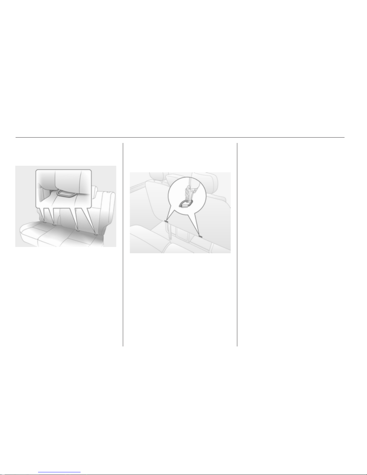
Top-tether fastening eyes
Top-Tether fastening eyes are
located on the back of the seat.
In addition to the ISOFIX mounting
fasten the Top-Tether strap to the
Top-Tether fastening eyes. The strap
must run between the two guide rods
of the head restraint.
ISOFIX child restraint systems of
universal category positions are
marked in the table by IUF.
Page 51
Storage 51
Storage
Storage compartments ................ 51
Load compartment ....................... 54
Roof rack system ......................... 57
Loading information ..................... 57
Storage compartments
Instrument panel storage
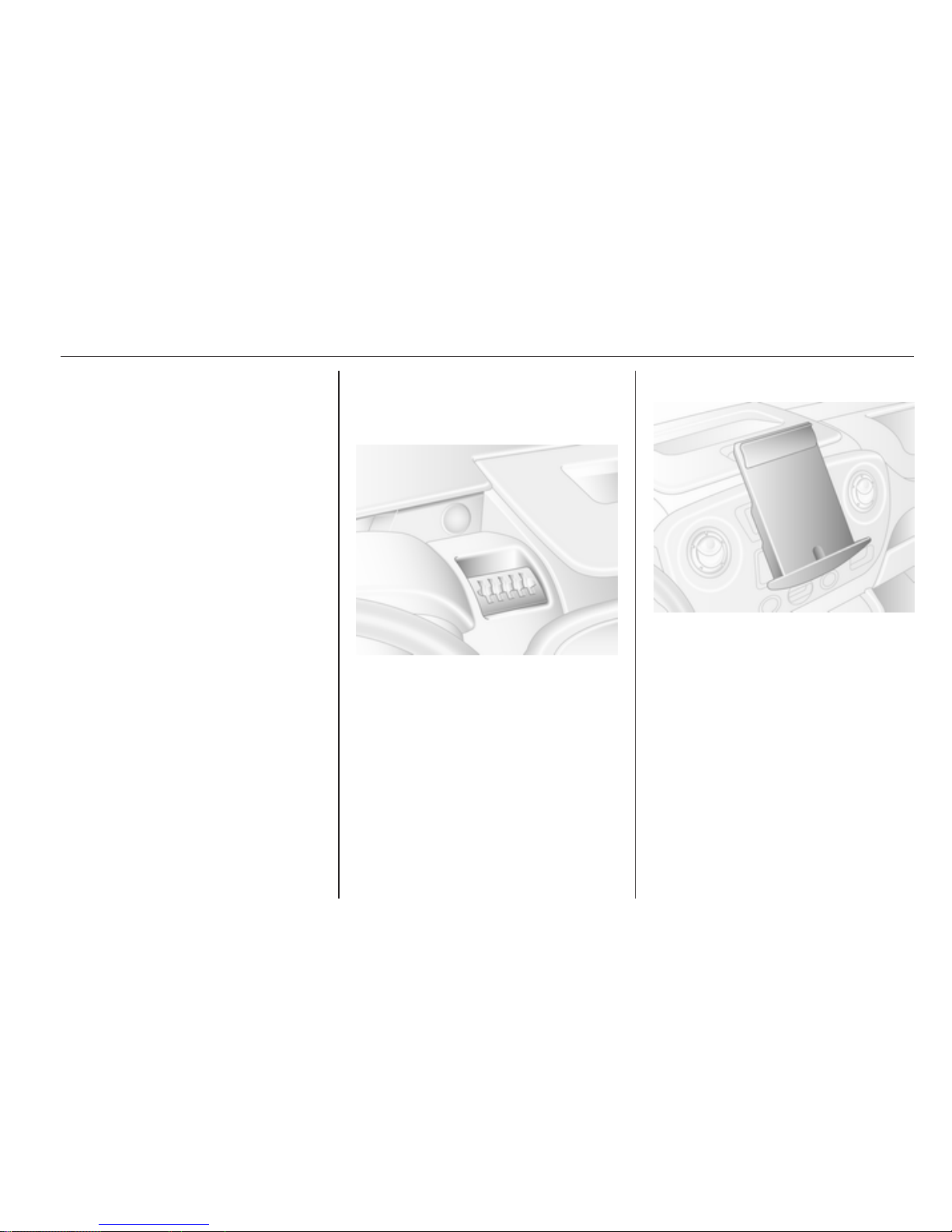
Storage compartments, pockets and
trays are located in the instrument
panel.
A phone pocket and coin holder with
a clip for holding tickets is located on
the top of the instrument panel.
The tray located centrally on top of the
instrument panel has a lid.
Document holder
Withdraw the document holder from
the instrument panel by pulling the
base towards you and then swivelling
it downwards. To fold away, raise the
base until the document holder is
horizontal, then push fully in.
Page 52
52 Storage
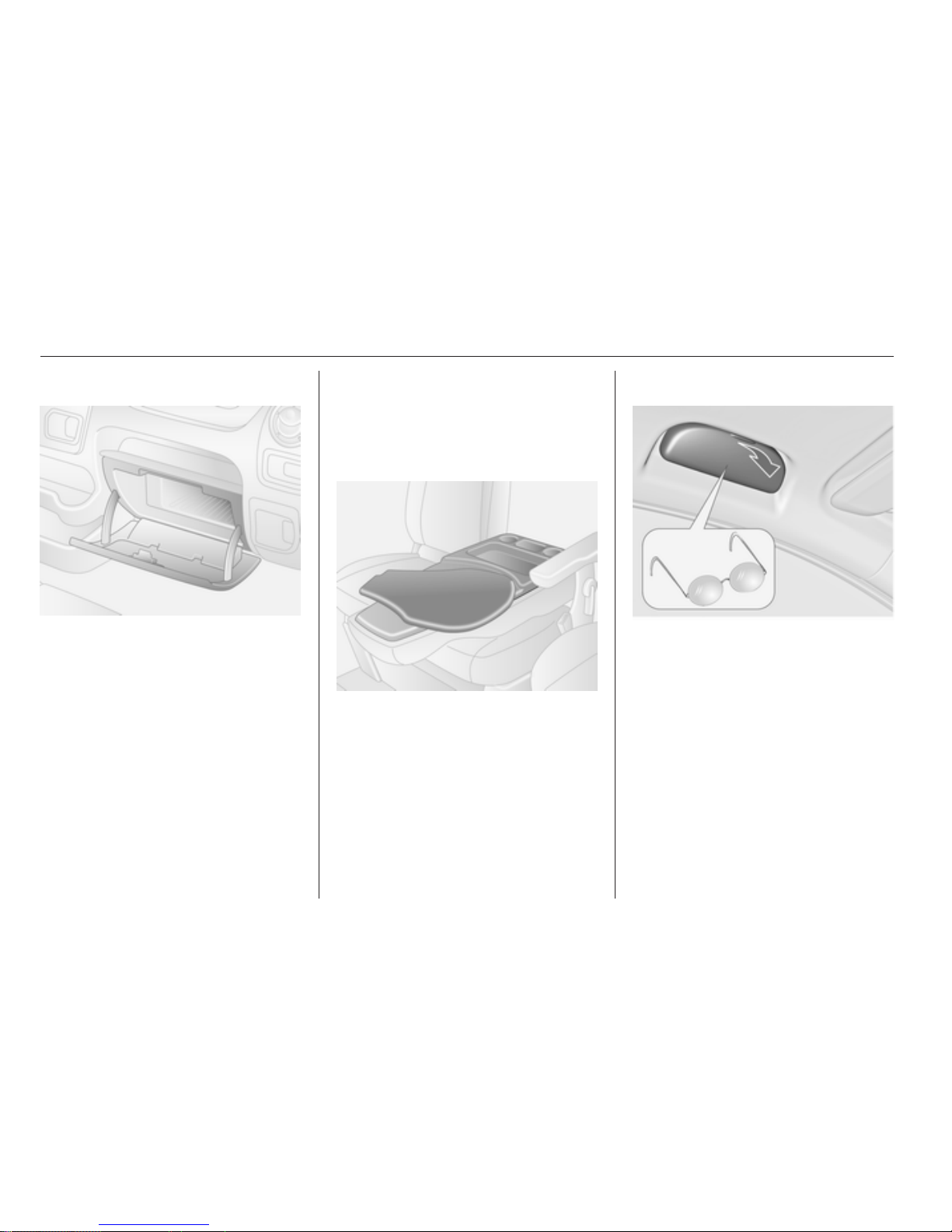
Glovebox
The glovebox should be closed whilst
driving.
Glovebox cooler 3 92.
Cupholders
Cupholders are located at either end
of the instrument panel and centrally
in the lower instrument panel.
The cupholders can also be used to
hold the portable ashtray unit.
Front storage
Three coat hooks are located on the
cabin bulkhead
Folding passenger seatback
The passenger seat backrest, when
folded fully forwards, features storage
compartments and drink holders.
The swivelling shelf, which can be
used for writing or documents, must
be returned to its original position
before raising the seat backrest.
Sunglasses storage
Fold down to open.
Do not use for storing heavy objects.
Page 53
Storage 53
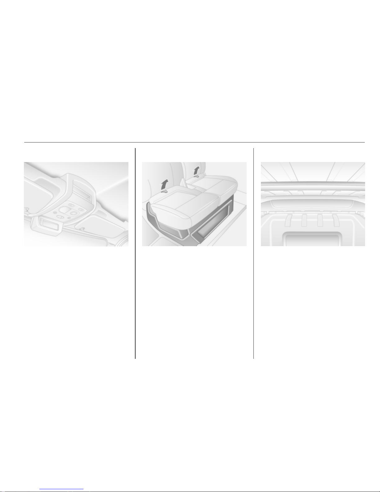
Overhead console
The total weight in these
compartments must not exceed 5 kg.
Underseat storage
Using the two loops on the passenger
seat cushion, pull the cushion
forwards to gain access to the storage
under the seat.
Overcab storage
The total weight in this compartment
must not exceed 35 kg.
Rear storage
Bus
Objects can be stored in the overhead
storage racks above the rear
passenger seating.
The total weight in each storage rack
must not exceed 35 kg.
Page 54
54 Storage
Load compartment
Lashing eyes
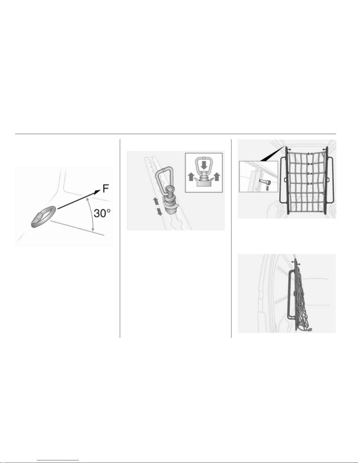
Lashing eyes are mounted in the load
compartment to enable cargo to be
secured in position using lashing
straps or a luggage floor net.
The maximum force applied to the
lashing eyes should not exceed
5000 N at 30°.
Removable lashing eyes
To reposition, press down on the
centre cap and slide to the desired
position. Ensure the lashing eye
engages correctly in the recess.
Loading information 3 57.
Cargo management
system
Moveable partition wall
The moveable partition wall can be
used between the floor and roof rails.
To move, pull down on the latch to
release and position the wall as
required. Ensure the latch engages
fully and the partition wall is upright.
Page 55
Storage 55
Store the partition wall to one side of
the load compartment when not in
use.
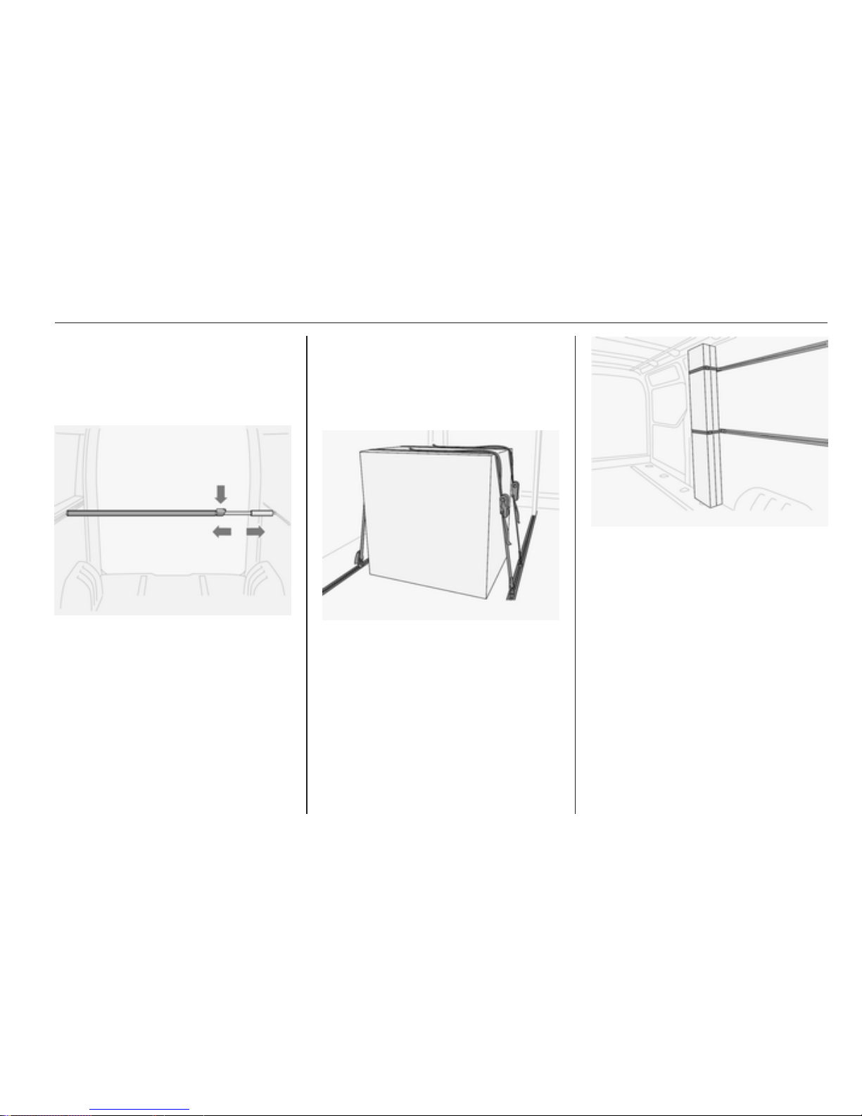
Telescopic blocking bars
The telescope blocking bars can be
used in a vertical or horizontal
position.
Ensure the blocking bars are fully
engaged in the load rails before
loading.
To release, press down on the lock
and slide the bar at the same time.
Maximum loading 100 daN/700mm.
Ratchet straps
Using the appropriate ratchet straps,
objects can be secured to the
removable lashing eyes in the side or
floor load rails.
Using the ratchet straps, secure the
object to the removable lashing eyes
in the vehicle floor.
Maximum loading 500 daN/700mm.
Maximum loading 100 daN/700mm.
Removable lashing eyes 3 54,
Loading information 3 57.
Page 56
56 Storage
Safety net
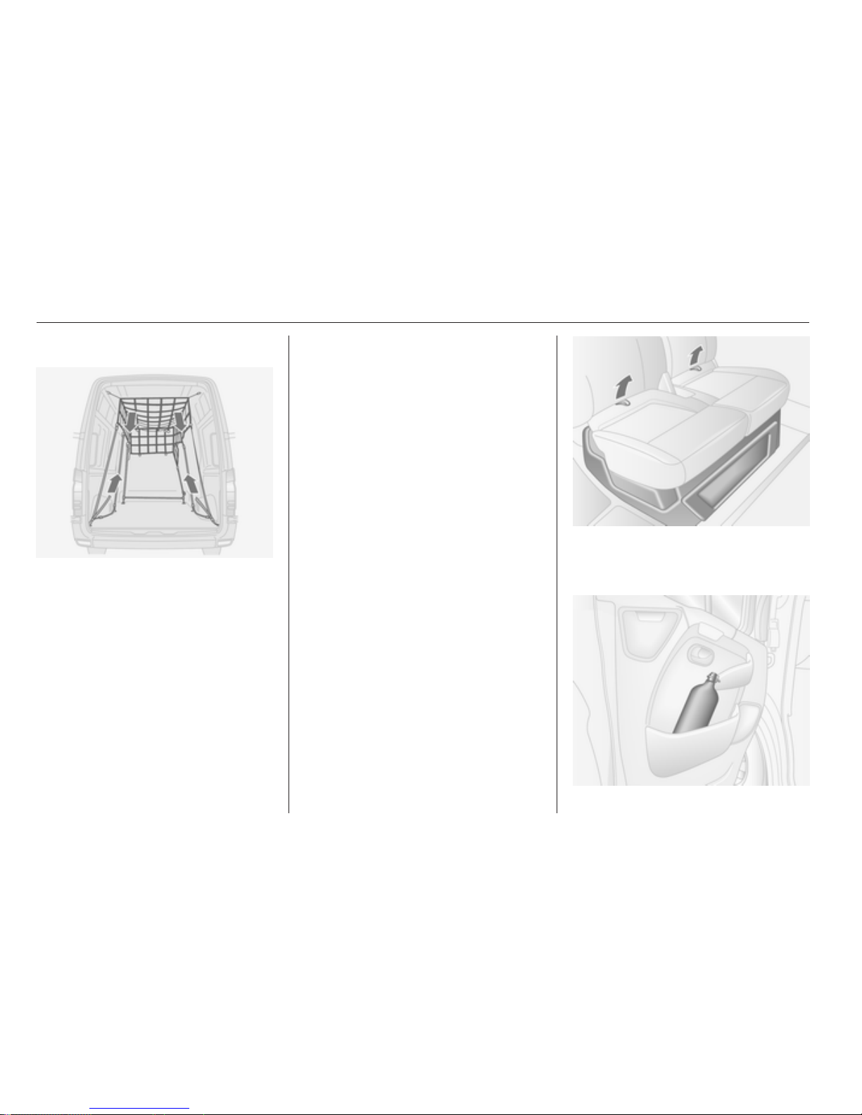
Lower the safety from the roof area
and attach to the lashing eyes 3 54.
Adjust the tension on the straps to
ensure the load is secure.
When not in use the safety net should
be stored in the roof area.
Loading information 3 57.
Warning triangle
The warning triangle can be
accommodated in the space under
the front passenger seat.
Underseat storage 3 53.
First aid kit
The first aid kit can be accommodated
in the space under the front
passenger seat or in the overhead
console.
A label is located on the overhead
console should the first aid kit be
stored there.
Underseat storage 3 53.
Overhead console 3 53.
Fire extinguisher
The fire extinguisher can be
accommodated in the space under
the front passenger seat.
Using the two loops on the passenger
seat cushion, pull the cushion
forwards to gain access.
Page 57

Storage 57
An additional extinguisher may be
located in the front door panel.
As a visible indication of this, a label
is located on the overhead console.
Roof rack system
Roof rack
For safety reasons and to avoid
damage to the roof, the vehicle
approved roof rack system is
recommended.
Follow the installation instructions
and remove the roof rack when not in
use.
Further information 3 57.
Loading information
■ Heavy objects in the load
compartment should be evenly
distributed and placed as far
forward as possible. If objects can
be stacked, the heavier objects
should be placed at the bottom.
■ Secure objects with lashing straps
attached to lashing eyes 3 54.
■ Secure loose objects in load
compartment to prevent sliding.
■ The load must not obstruct the
operation of the pedals, parking
brake and gear selector, or hinder
the freedom of movement of the
driver. Do not place any unsecured
objects in the interior.
■ Do not drive with an open load
compartment. In addition, the
number plate is only
distinguishable and illuminated
correctly if the doors are closed.
■ The payload is the difference
between the permitted gross
vehicle weight (see identification
Page 58

58 Storage
plate 3 153) and the EC kerb
weight.
To calculate the EC kerb weight,
enter the data for your vehicle in the
Weights table at the front of this
manual.
The EC kerb weight includes
weights for the driver (68 kg),
luggage (7 kg) and all fluids (tank
90% full).
Optional equipment and
accessories increase the kerb
weight.
■ Driving with a roof load increases
the sensitivity of the vehicle to
cross-winds and has a detrimental
effect on vehicle handling due to
the vehicle's higher centre of
gravity. Distribute the load evenly
and secure it properly with retaining
straps. Adjust the tyre pressure and
vehicle speed according to the load
conditions. Check and retighten the
straps frequently.
■ The permissible roof load (which
includes the weight of the roof rack)
is 200 kg for standard roof variants.
The roof load is the combined
weight of the roof rack and the load.
Page 59
Instruments and controls 59
Instruments and
controls
Controls ....................................... 59
Warning lights, gauges and
indicators ..................................... 64
Information displays ..................... 73
Vehicle messages ........................ 73
Trip computer ............................... 74
Tachograph .................................. 75
Controls
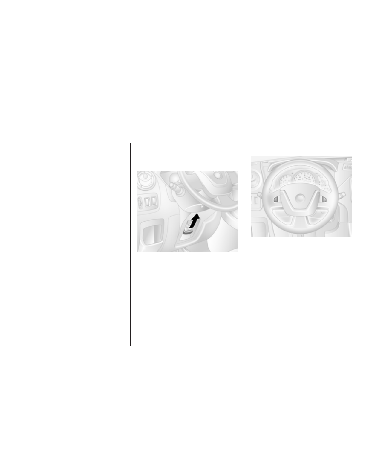
Steering wheel adjustment
Unlock lever, adjust steering wheel,
then engage lever and ensure it is
fully locked.
Do not adjust steering wheel unless
vehicle is stationary and steering
wheel lock has been released.
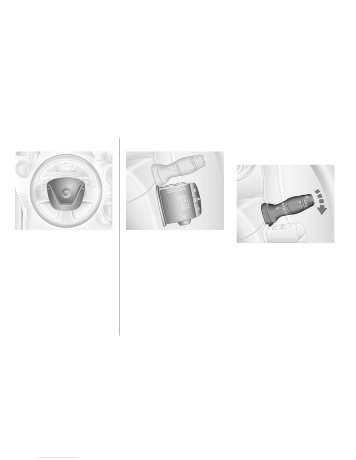
Steering wheel controls
The cruise control and speed limiter
can be operated via the controls on
the steering wheel.
Cruise control 3 106.
Page 60
60 Instruments and controls
Horn
Press j.
Steering column controls
The Infotainment system can be
operated via the controls on the
steering column.
Further information is available in the
Infotainment manual.
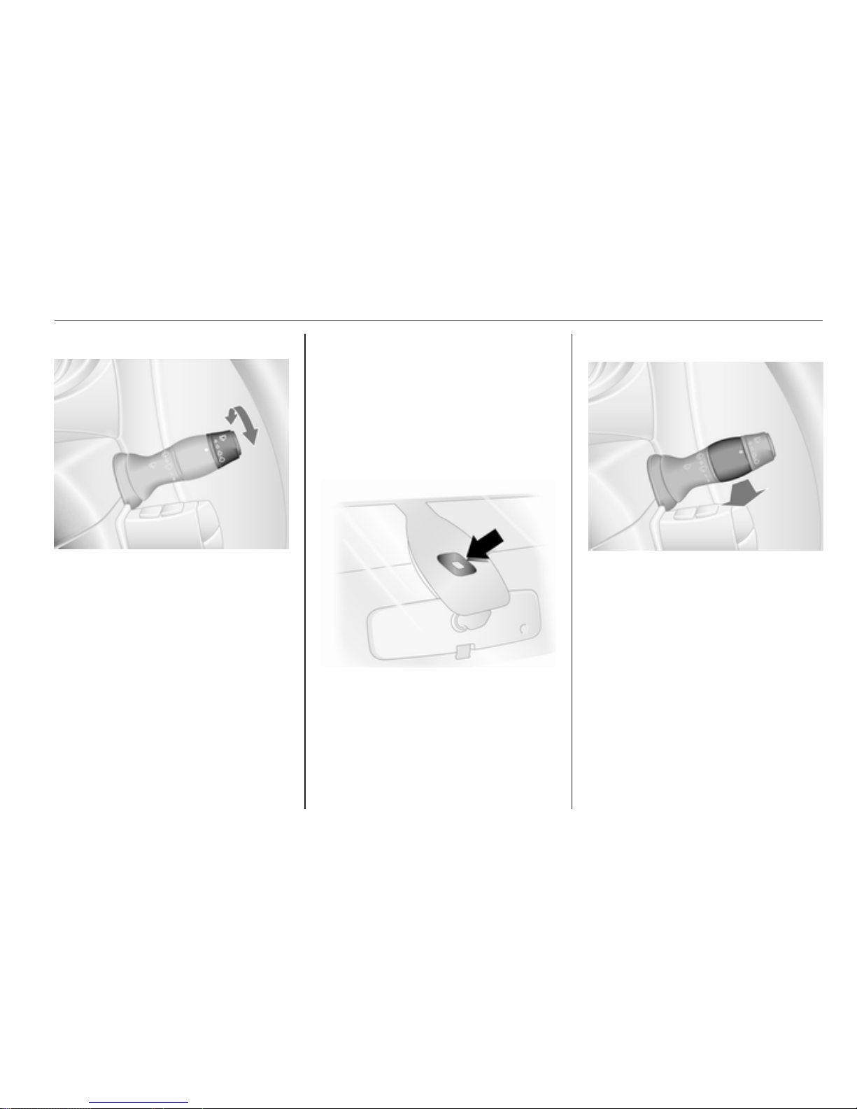
Windscreen wiper/washer
Windscreen wiper
K
= timed interval wipe
1 = slow
2 = fast
Do not use if the windscreen is frozen.
Switch off in car washes.
Page 61
Instruments and controls 61
Automatic wiping with rain sensor
K
= automatic wiping with rain
sensor
The rain sensor detects the amount of
water on the windscreen and
automatically regulates the frequency
of the windscreen wipers.
Upon starting the engine, automatic
wiping will need to be reselected.
Adjustable sensitivity of the rain
sensor
Turn the adjuster wheel to adjust the
sensitivity:
low
sensitivity
= turn adjuster wheel
downwards
high
sensitivity
= turn adjuster wheel
upwards
Keep the sensor free from dust, dirt
and ice.
Windscreen washer
Pull lever. Washer fluid is sprayed
onto the windscreen.
short pull = wiper swipes once
long pull = wiper swipes for a few
strokes
Page 62
62 Instruments and controls
Outside temperature
A drop in temperature is indicated
immediately and a rise in temperature
after a time delay.
If outside temperatures drop to 3 °C,
the °C flashes in the information
display as a warning for icy road
conditions. This will continue to flash
until temperatures rise above 3 °C.
9 Warning
The road surface may already be
icy even though the display
indicates a few degrees above
0 °C.
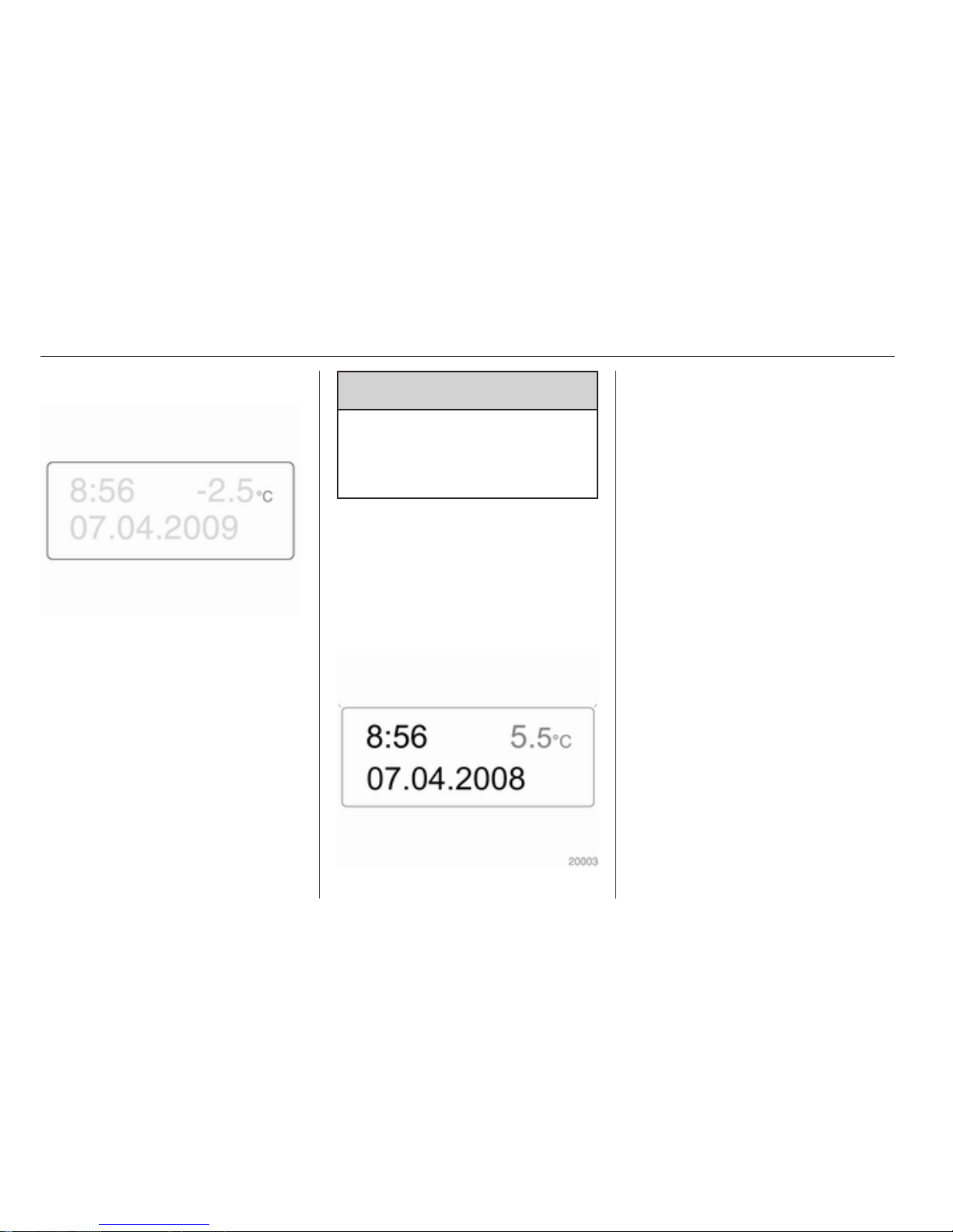
Clock
Date and time are shown in the
information display or time only in the
multifunction display.
Set date and time in information
display
The Infotainment system must be off.
Activate setting mode by holding the
Ö button depressed for approx.
2 seconds. The flashing value is
adjusted using the ; button. The Ö
button is used to switch to the next
mode and to exit setting mode.
Set time in multifunction display
With the time displayed press and
hold the bottom button on the end of
the wiper lever, until the hour setting
flashes. Press the top button and the
hours reading will advance.
Press and hold the bottom button on
the end of the wiper lever, until the
minute setting flashes. Press the top
button and the minute reading will
advance.
Press and hold the lower button on
the end of the wiper lever to exit
setting mode.
Trip computer 3 74.
Page 63
Instruments and controls 63
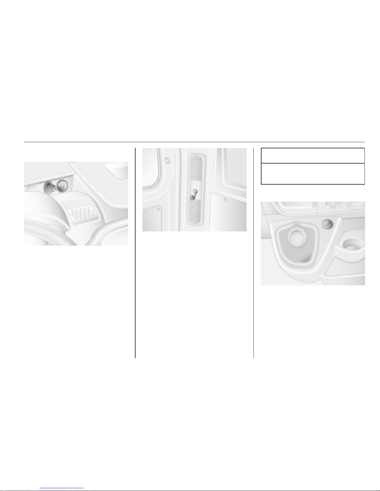
Power outlets
12 V power outlets are located in the
instrument panel and in the rear of the
vehicle.
Connecting electrical accessories
while the engine is off will discharge
the battery. Do not exceed the
maximum power consumption of
120 watts. Do not connect any
current-delivering accessories, e.g.
electrical charging devices or
batteries.
Electrical accessories that are
connected must comply with the
electromagnetic compatibility
requirements laid down in
DIN VDE 40 839.
Do not connect any current-delivering
accessories, e.g. electrical charging
devices or batteries.
Caution
Do not damage the outlet by using
unsuitable plugs.
Cigarette lighter
Press in cigarette lighter. It switches
off automatically once the element is
glowing. Pull out lighter.
Page 64
64 Instruments and controls
Ashtrays
Caution
To be used only for ash and not for
combustible rubbish.
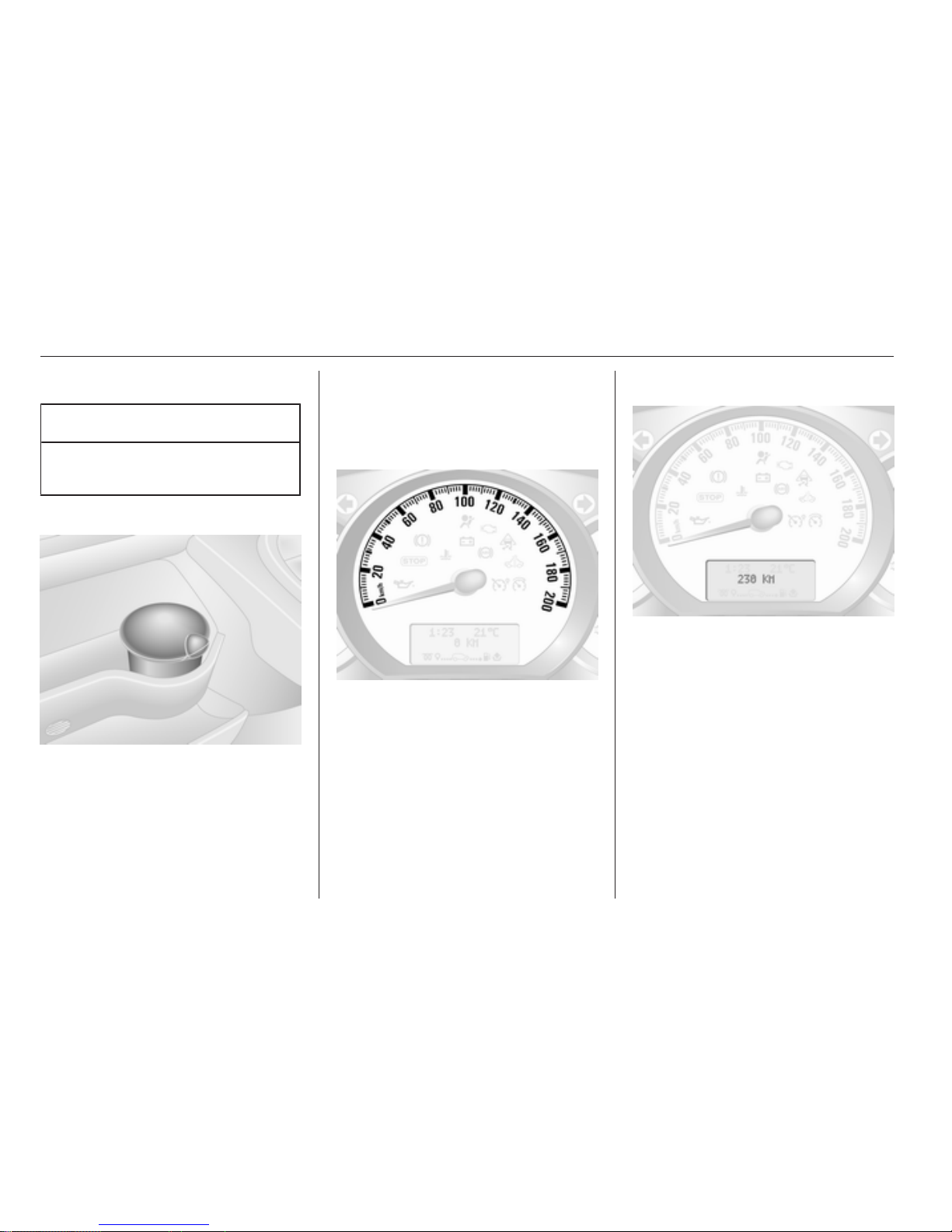
Portable ashtray
Ashtray container for mobile use in
the vehicle. To use, open cover.
Warning lights, gauges
and indicators
Speedometer
Indicates vehicle speed.
Maximum speed may be restricted by
a speed regulator. As a visible
indication of this, a warning label is
located on the instrument panel.
Note
Under certain conditions (e.g. steep
inclines) the vehicle speed may
exceed the set limit.
Odometer
Displays the recorded distance.
Trip odometer
Press either button once on the end
of the windscreen wiper lever to
display the trip odometer.
To reset, press and hold either button
for a few seconds with the ignition on.
The display will flash and reset to
zero.
Page 65
Instruments and controls 65
Tachometer
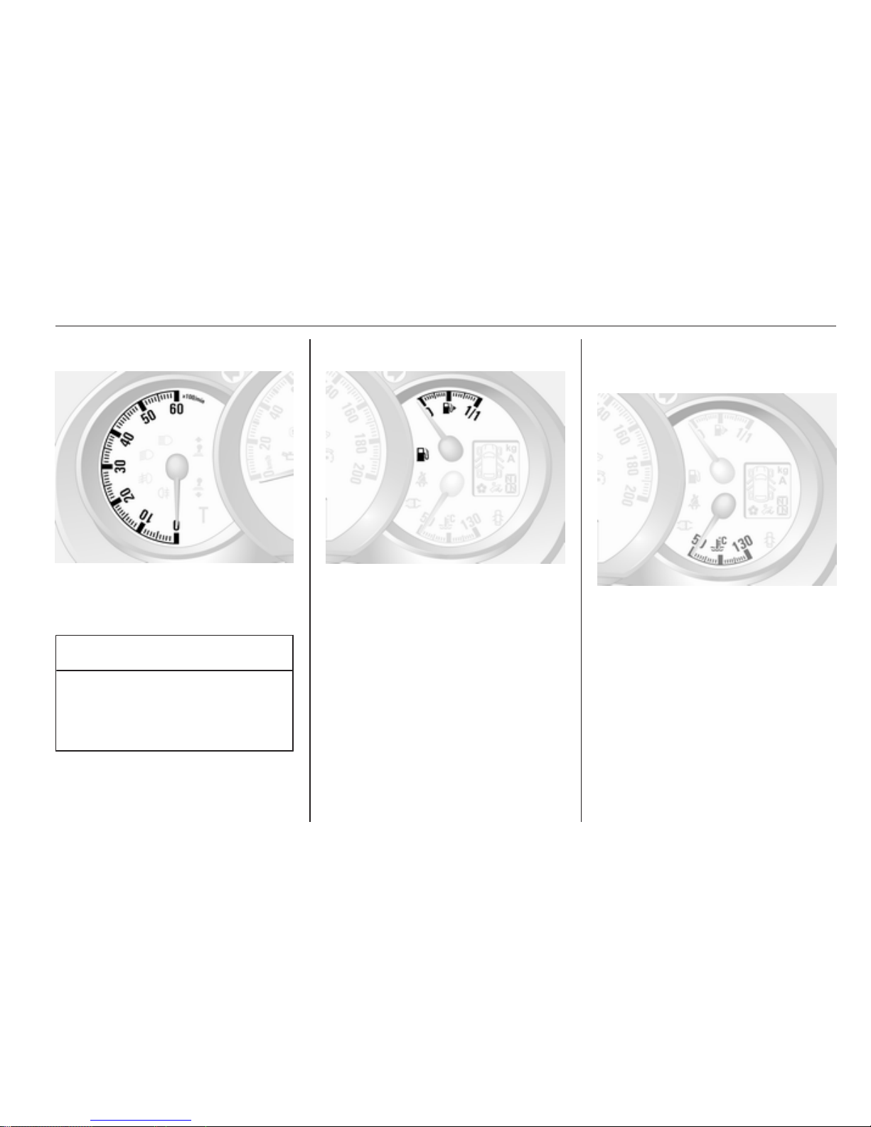
Displays the engine speed.
Drive in a low engine speed range for
each gear as much as possible.
Caution
If the needle is in the red warning
zone, the maximum permitted
engine speed is exceeded. Engine
at risk.
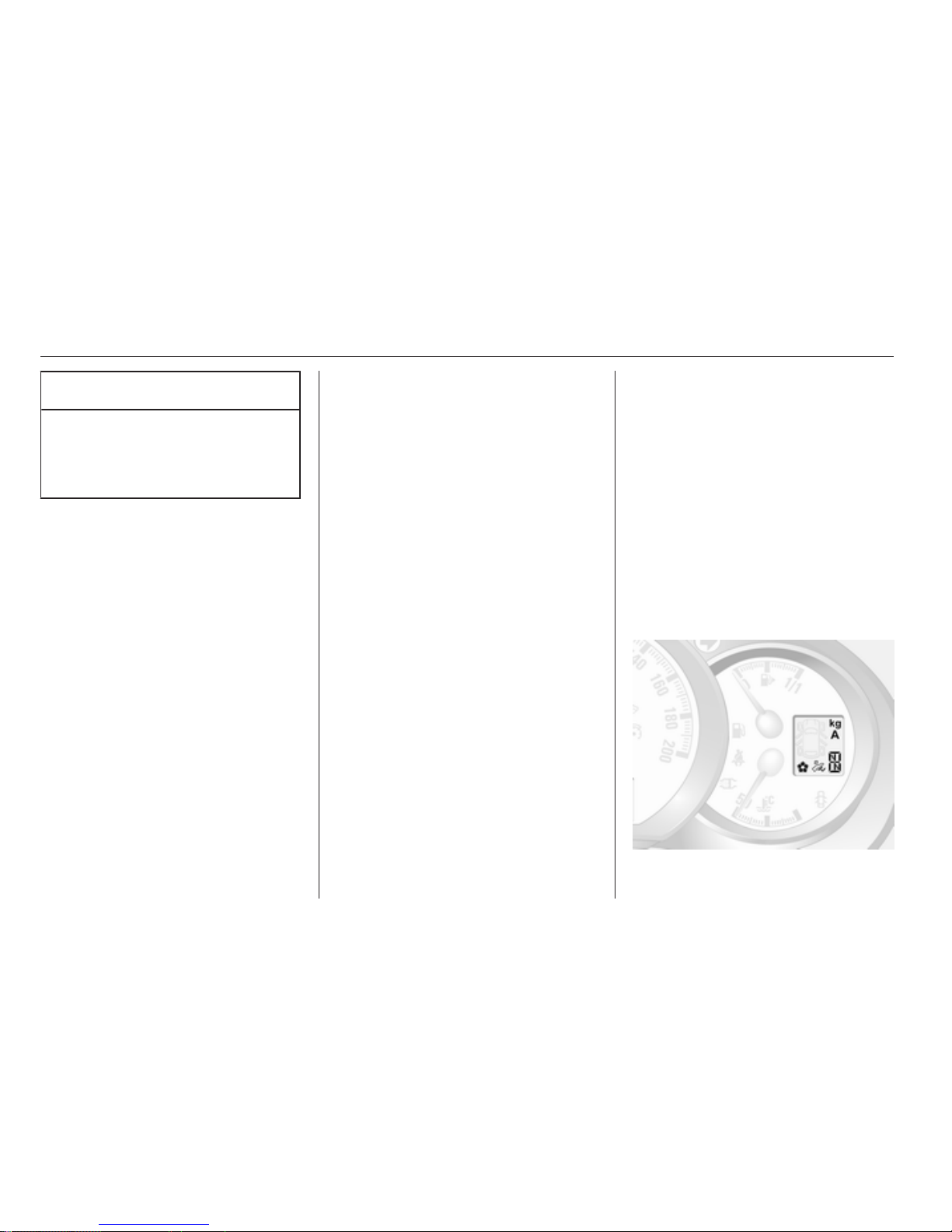
Fuel gauge
Displays the fuel level in the tank.
Control indicator Y illuminates if the
level in the tank is low. Refuel
immediately.
Never run the tank dry.
Because of the fuel remaining in the
tank, the top-up quantity may be less
than the specified tank capacity.
Engine coolant
temperature gauge
Displays the coolant temperature.
left area = engine operating
temperature not yet
reached
central
area
= normal operating
temperature
right area = temperature too high
Control indicator W illuminates if the
temperature is too high 3 70.
Page 66
66 Instruments and controls
Caution
If engine coolant temperature is
too high, stop vehicle, switch off
engine. Danger to engine. Check
coolant level.
For physical reasons, the coolant
temperature gauge shows the coolant
temperature only if the coolant level is
adequate.
Engine oil level monitor
If the engine oil level is correct when
the ignition is switched on OIL LEVEL
CORRECT appears briefly in the
multifunction display.
If the engine oil is above the minimum
level, press either trip computer
button within 30 seconds of the
ignition being switched on. OIL
LEVEL is displayed in combination
with the squares to indicate the oil
level. As the oil level diminishes, the
squares in the display are replaced
with dashes.
= Maximum level
___ = Intermediate level
______ = Minimum level
If the minimum engine oil level is
reached TOP-UP OIL LEVEL is
displayed in combination with A
after the ignition is switched on for
30 seconds. Check and top up engine
oil 3 118.
To exit the oil level monitor display,
press either trip computer button. Trip
computer 3 74.
Service display
Based on driving conditions, the
interval at which a service will be
indicated can vary considerably.
When the remaining distance before
the next service is less than
3000 km or two months, SERVICE
IN appears in the multifunction
display.
When the distance reaches 0 km or
the service date is due, o and A will
illuminate and SERVICE DUE
appears in the multifunction display.
The vehicle needs a service.
Seek the assistance of a workshop.
Resetting the service display
Select the distance before service
display function in the trip computer.
Press and hold either button on the
end of the wiper lever until the
distance before service is displayed
continuously.
Trip computer 3 74.
Transmission display
Page 67

Instruments and controls 67
The mode or selected gear of the
manual transmission automated is
shown in the transmission display.
R = Reverse gear
N = Neutral
A = Automatic mode
kg = Laden mode
V
= Winter mode
T
= Apply footbrake
W
= Transmission electronics
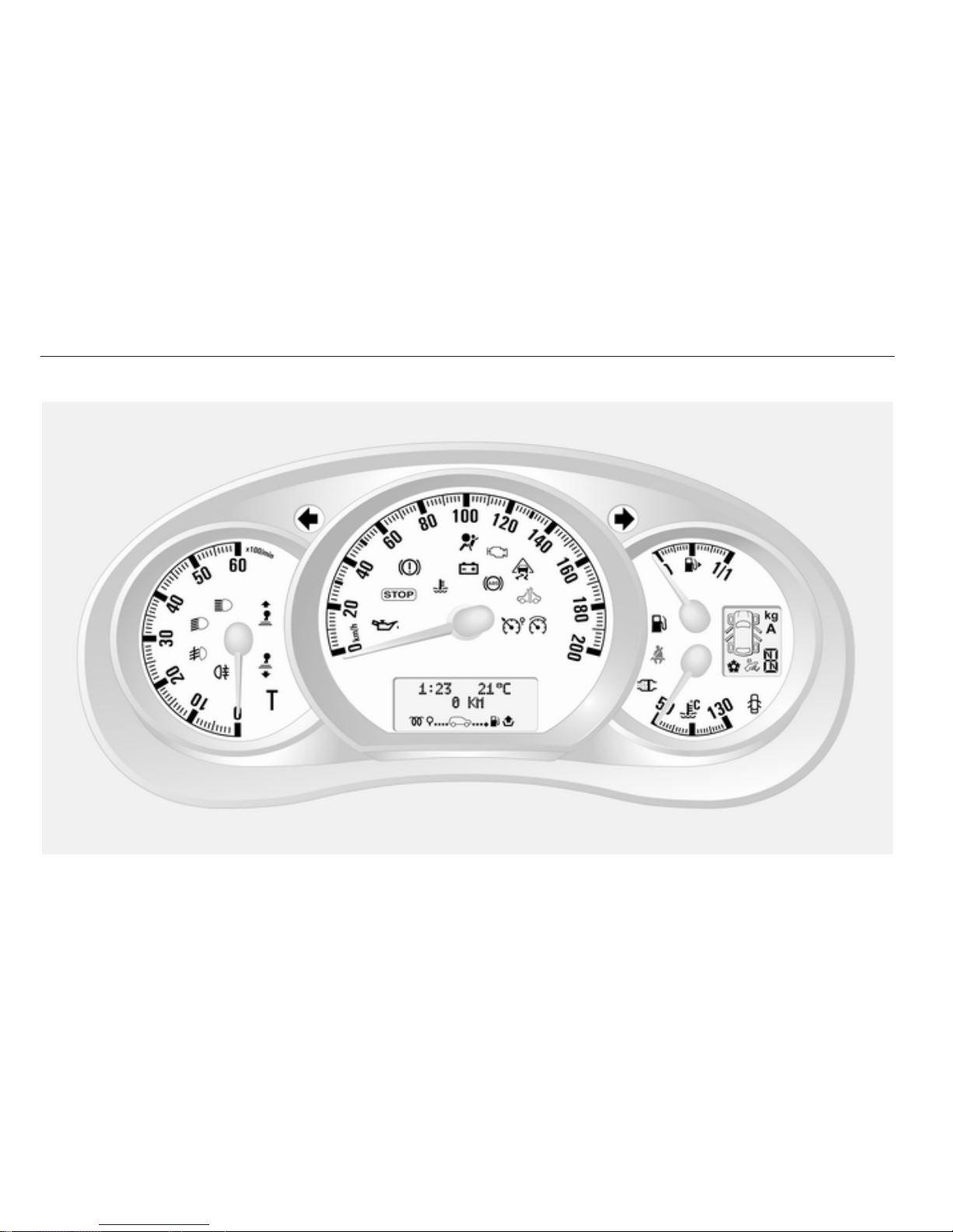
Control indicators
The control indicators described are
not present in all vehicles. The
description applies to all instrument
versions. When the ignition is
switched on, most control indicators
will illuminate briefly as a functionality
test.
The control indicator colours mean:
red = danger, important
reminder
yellow = warning, information, fault
green = confirmation of activation
blue = confirmation of activation
Page 68
68 Instruments and controls
Control indicators in the instrument cluster
Page 69
Instruments and controls 69
Turn signal
O flashes green.
Flashes if a turn signal or the hazard
warning flashers are activated.
Rapid flashing: failure of a turn signal
light or associated fuse.
An audible warning can be heard
when the turn signals are on. When
towing a trailer, the pitch of the
audible warning changes.
Bulb replacement 3 123.
Fuses 3 130.
Turn signals 3 78.
Airbag and belt tensioners
v illuminates yellow.
When the ignition is switched on, the
control indicator illuminates briefly. If
it does not illuminate or illuminates
whilst driving, there is a fault in the
airbag or pretensioner system. The
airbags and belt pretensioners may
fail to trigger in the event of an
accident.
Deployment of the belt pretensioners
or airbags is indicated by continuous
illumination of v.
9 Warning
Have the cause of the fault
remedied immediately by
a workshop.
Belt pretensioners, airbag system
3 37, 3 40.
Airbag deactivation
W illuminates yellow when the
ignition is switched on and remains
illuminated when the front passenger
airbag has been deactivated 3 42.
If control indicator A is illuminated in
conjunction with v, seek the
assistance of a workshop.
9 Danger
Risk of fatal injury for a child using
a child restraint system together
with activated front passenger
airbag.
Risk of fatal injury for an adult
person with deactivated front
passenger airbag.
Charging system
p illuminates red.
Illuminates when the ignition is
switched on and goes out shortly after
the engine starts.
Illuminates when the engine is
running
Stop, switch off engine. Battery is not
charging. Engine cooling may be
interrupted. Power to the brake servo
unit may be cut. Seek the assistance
of a workshop.
Malfunction indicator light
Z illuminates or flashes yellow.
Page 70
70 Instruments and controls
Illuminates when the ignition is
switched on and goes out shortly after
the engine starts.
Illuminates when the engine is
running
Fault in the emission control system.
The permitted emission limits may be
exceeded. Seek the assistance of
a workshop immediately.
Flashes when the engine is
running
Fault that could lead to catalytic
converter damage. Ease up on the
accelerator until the flashing stops.
Seek the immediate assistance of
a workshop.
Stop engine
C illuminates red.
Illuminates for a few seconds when
the ignition is switched on.
If C illuminates in combination with
W or R, stop engine immediately and
seek the assistance of a workshop.
Depending on the type of fault,
a warning message may also appear
in the multifunction display.
System check
A illuminates in red.
Illuminates when the ignition is
switched on and goes out shortly after
the engine starts.
May illuminate in combination with
another warning light or message in
the multifunction display. Seek the
assistance of a workshop
immediately.
Brake system
R illuminates red.
Illuminates when the parking brake is
released if the brake fluid level is too
low 3 120.
9 Warning
Stop. Do not continue your
journey. Consult a workshop.
Illuminates after the ignition is
switched on if the parking brake is
applied 3 103.
Brake pad wear
F illuminates yellow.
Illuminates when the brake pads are
worn 3 102.
Seek the assistance of a workshop.
Antilock brake system
(ABS)
u illuminates yellow.
Illuminates briefly after the ignition is
switched on. The system is ready for
operation when u goes out.
If control indicators u and A
illuminate with the messages CHECK
ABS and CHECK ESP in the
multifunction display, there is a fault
in the ABS. The brake system
remains operational but without ABS
regulation.
Page 71

Instruments and controls 71
If control indicators u, A, R and
C illuminate, the ABS and ESP are
deactivated and the message
BRAKING FAULT is displayed. Seek
the assistance of a workshop.
Antilock brake system 3 103.
Upshift
k or j illuminates.
It is recommended to shift gear when
illuminated for economical reasons.
Electronic Stability
Program
v flashes or illuminates yellow.
Illuminates for a few seconds when
the ignition is switched on.
Flashing during driving
The system is actively engaged.
Engine output may be reduced and
the vehicle may be braked
automatically to a small degree
3 105.
Illuminates while driving
The system is switched off. The
message ESP OFF will also appear in
the multifunction display.
ESP®
Plus
3 105.
Engine electronics
k illuminates yellow.
Illuminates when the engine is
running
Indicates a fault in the electronic
system.
Seek the assistance of a workshop.
Engine oil pressure
I illuminates red.
Illuminates when the ignition is
switched on and goes out shortly after
the engine starts.
Illuminates when the engine is
running
Caution
Engine lubrication may be
interrupted. This may result in
damage to the engine and/or
locking of the drive wheels.
1. Depress clutch.
2. Select neutral gear, set selector
lever to N.
3. Move out of the flow of traffic as
quickly as possible without
impeding other vehicles.
4. Switch off ignition.
Page 72

72 Instruments and controls
9 Warning
When the engine is off,
considerably more force is needed
to brake and steer.
Do not remove key until vehicle is
stationary, otherwise the steering
wheel lock could engage
unexpectedly.
Check oil level before seeking
assistance of a workshop 3 118.
Low fuel
Y illuminates yellow.
Illuminates when level in fuel tank is
too low.
Catalytic converter 3 97.
Bleeding the diesel fuel system
3 122.
Drain fuel filter
Q illuminates yellow.
Illuminates when the ignition is
switched on and goes out shortly after
the engine starts.
Illuminates when the engine is
running
Indicates the presence of water in the
diesel. Seek the assistance of
a workshop immediately.
Exterior light
9 illuminates green.
Illuminated when the exterior lights
are on 3 76.
High beam
P illuminates blue.
Illuminated when high beam is on and
during headlight flash 3 77.
Fog light
> illuminates green.
Illuminated when the front fog lights
are on 3 78.
Rear fog light
r illuminates yellow.
Illuminated when the rear fog light is
on 3 79.
Cruise control
m, U illuminates green.
m illuminates green when a certain
speed is stored.
U illuminates green when the system
is on.
Speed limiter
U illuminates orange.
U illuminates orange when the
system is on.
Cruise control, Speed limiter 3 106.
Door open
U illuminates red.
Illuminates when a door is open.
Page 73
Instruments and controls 73
Information displays
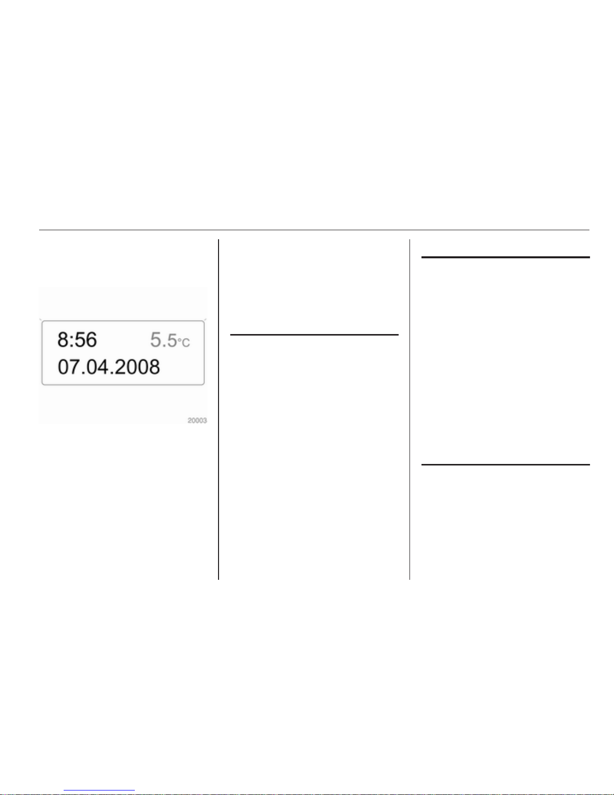
Triple-Info-Display
Displays time, outside temperature
and date when the ignition is on.
Vehicle messages
Messages appear in the multifunction
display, in combination with A or C.
Information messages
Information messages
BATTERY MODE: ECONOMY
ESP OFF
AUTO LIGHTS DEACTIVATED
OIL LEVEL CORRECT
Fault messages
Displayed in combination with A.
Drive with caution and seek the
assistance of a workshop.
To remove fault message, press
either button on the end of the wiper
lever. After a few seconds the
message may disappear
automatically and A remains
illuminated. The fault will then be
stored in the on board system.
Fault messages
CHECK ESP
CHECK FUEL FILTER
CHECK GEARBOX
CHECK AUTO LIGHTS
Warning messages
These may appear with C or in
combination with other warning
messages, control indicators or an
audible warning. Stop engine
immediately and seek the assistance
of a workshop.
Warning messages
INJECTION FAULT
ENGINE OVERHEATING
GEARBOX OVERHEATING
Page 74
74 Instruments and controls
Warning chimes
When starting the engine or
whilst driving
■ During operation of the turn and
lane-change signals.
■ If the low fuel control indicator
illuminates.
■ If seat belt is not fastened.
■ If the vehicle has manual
transmission automated and the
clutch temperature is too high.
When the vehicle is parked and
the driver's door is opened
■ With exterior lights on.
■ If the vehicle has manual
transmission automated and the
parking brake is not applied, neutral
is not selected or the foot brake is
not depressed.
Trip computer
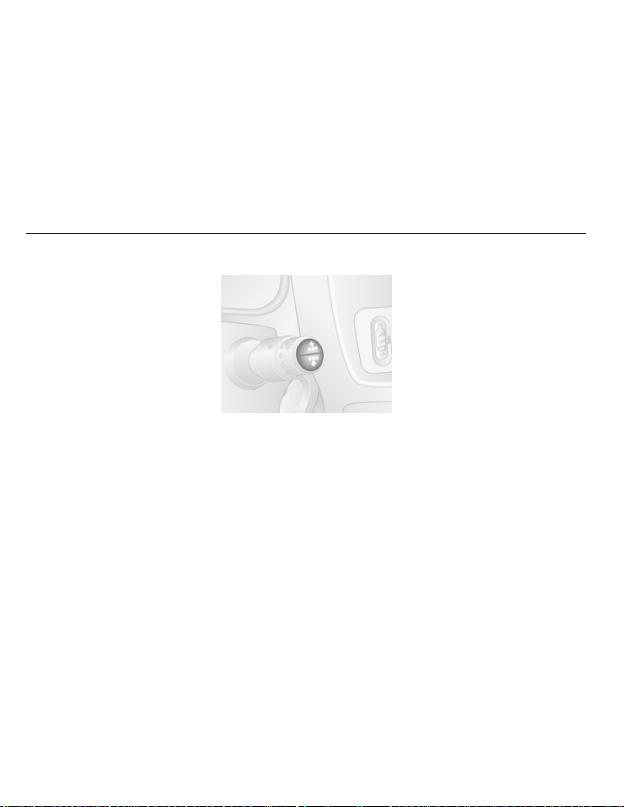
The functions can be selected by
pressing either button repeatedly on
the end of the wiper lever.
Press the button to select one of the
functions:
■ Fuel used
■ Average consumption
■ Instantaneous consumption
■ Range
■ Distance travelled
■ Average speed
■ Mileage before service interval
■ Cruise control and speed limiter
stored speed
■ Fault and information messages
shown in the multifunction display
Fuel used
Displays the amount of fuel
consumed since the last reset.
The measurement can be restarted at
any time by pressing and holding
either button.
Average consumption
The value is displayed after driving
a distance of 400 metres.
Average consumption is displayed,
taking into consideration the distance
travelled and the fuel used since the
last reset.
The measurement can be restarted at
any time.
Instantaneous consumption
The value is displayed after reaching
a speed of 30 km/h.
Page 75
Instruments and controls 75
Range
The value is displayed after driving
a distance of 400 metres.
The range is calculated from the
current contents of the fuel tank and
the average consumption since the
last reset.
The measurement can be restarted at
any time.
Distance travelled
Displays the distance driven since the
last reset.
The measurement can be restarted at
any time.
Average speed
The value is displayed after driving
a distance of 400 metres.
The average speed is displayed,
since the last reset.
The measurement can be restarted at
any time.
Interruptions in the journey with the
ignition off are not included in the
calculations.
Reset trip computer information
To reset the trip computer, select one
of its functions then press and hold
either button.
The trip computer will reset
automatically when the maximum
value of any of the parameters is
exceeded.
Tachograph
The tachograph is operated as
described in the operating
instructions supplied. Observe
regulations regarding use.
Page 76
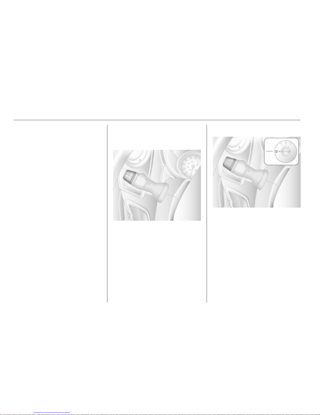
76 Lighting
Lighting
Exterior lighting ............................ 76
Interior lighting ............................. 79
Lighting features .......................... 81
Exterior lighting
Light switch
Turn light switch:
7
= Off
0
= Side lights
9 P
= Headlights
AUTO = Automatic light control
>
= Front fog lights
r
= Rear fog lights
High beam control indicator P 3 72.
Low beam control indicator 9 3 72.
Automatic light control
Light switch set to AUTO: When the
engine is running, headlights are
switched on when external light
conditions are poor.
For reasons of safety, the light switch
should always remain in the AUTO
position.
The headlights go off automatically
when the ignition is switched off.
Page 77
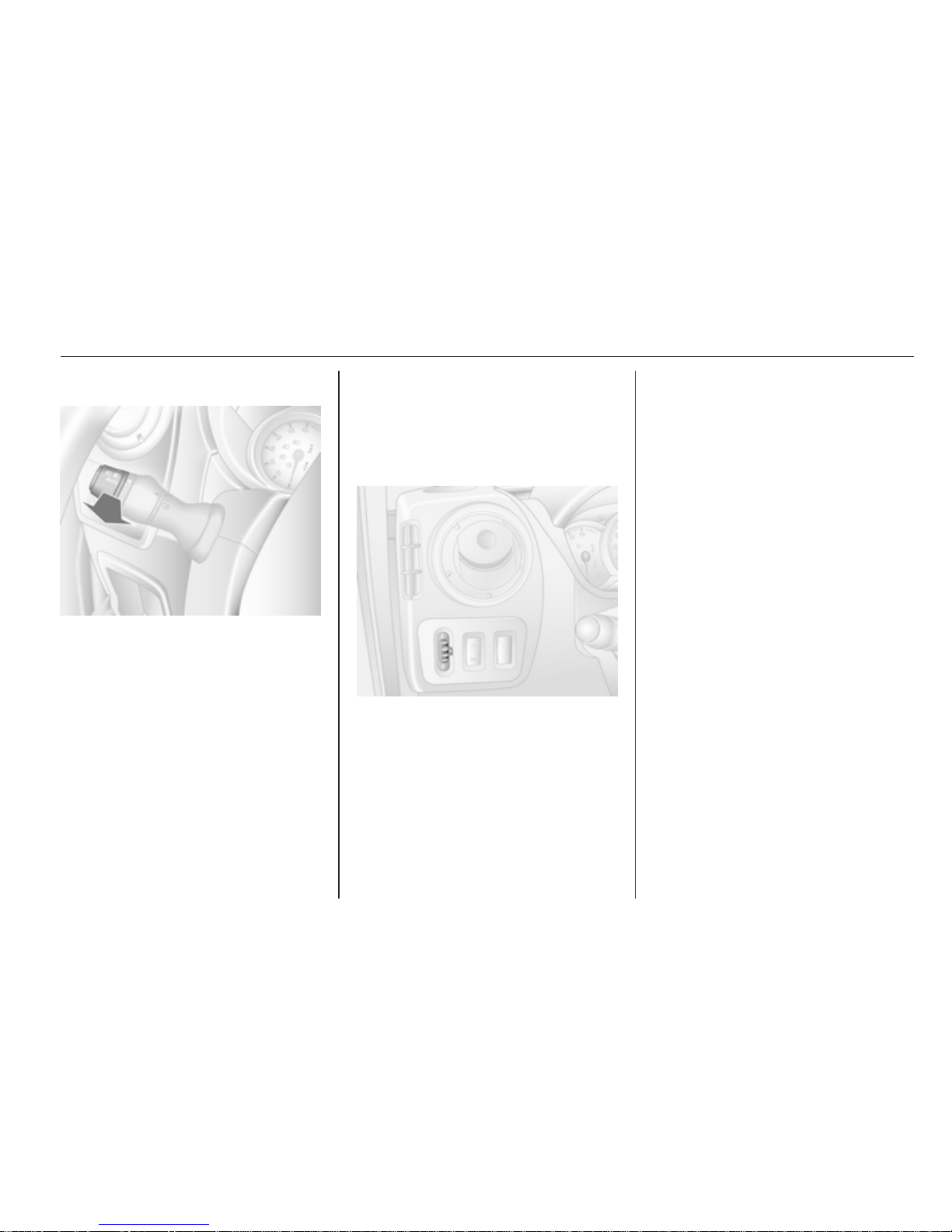
Lighting 77
High beam
To change between low and high
beam, pull lever until a click is felt.
Headlight flash
To activate the headlight flash, pull
lever.
Headlight range
adjustment
Manual headlight range
adjustment
To adapt headlight range to the
vehicle load to prevent dazzling: turn
knob to required position.
0 = Front seat occupied
4 = Loaded up to permissible
maximum weight
Headlights when driving
abroad
The asymmetrical headlight beam
extends visibility at the edge of the
road at the passenger side.
However, when driving in countries
where traffic drives on the opposite
side of the road, adjust the headlights
to prevent dazzling.
Have the headlights adjusted by
a workshop.
Daytime running lights
Daytime running lights increase
visibility of the vehicle during daylight.
When the ignition is on, the headlights
come on and instrument illumination
is subdued.
The daytime running lights switch off
when the ignition is switched off.
Page 78
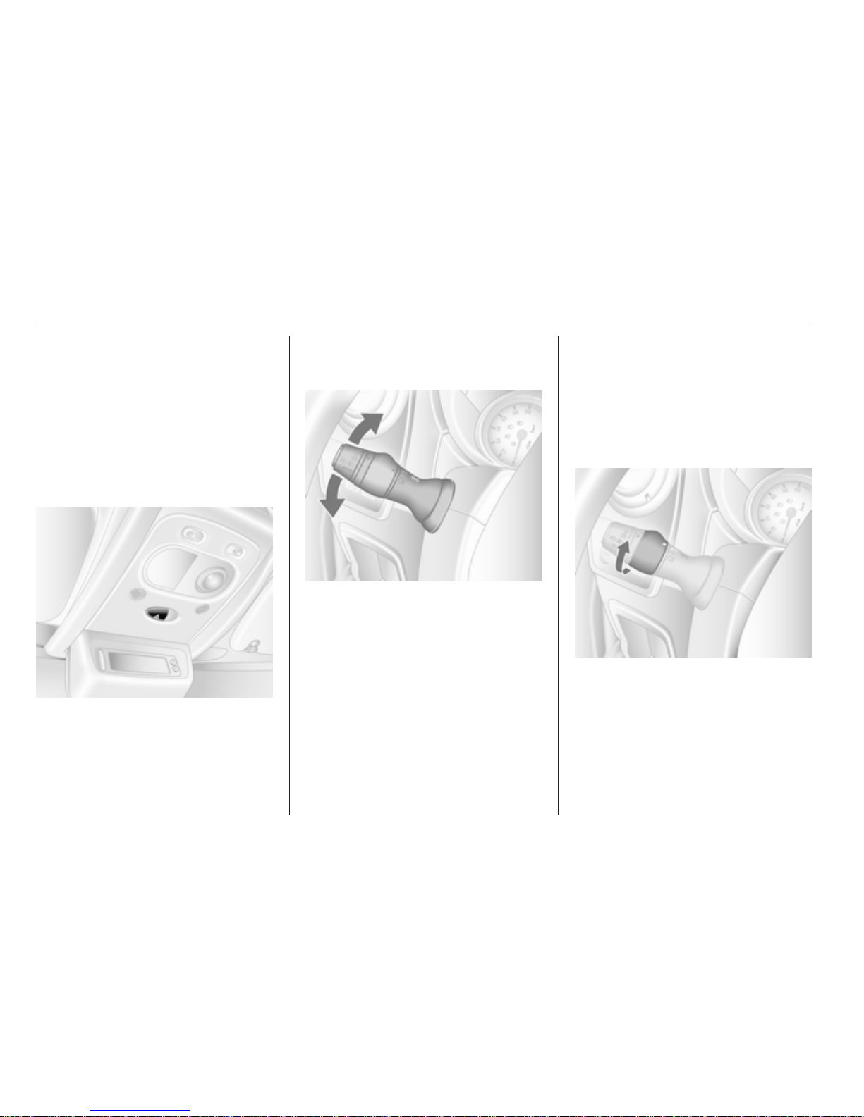
78 Lighting
Adaptive forward lighting
Cornering light
Depending on the steering angle,
vehicle speed and gear selected
when cornering, an additional light
will illuminate the corner of the road.
Hazard warning flashers
Operated with the ¨ button.
Turn and lane-change
signals
Lever up = right turn signal
Lever down = left turn signal
When the steering wheel is turned
back, the lever automatically returns
to its original position and the
indicator is deactivated. This will not
happen when making a minor
steering manoeuvre such as lane
changing.
When lane changing, move lever part
way to first stop. When released,
lever will spring back.
If the lever is moved past the first stop,
the indicator is switched on
constantly. Switch the indicator off
manually by moving the lever to its
original position.
Front fog lights
Turn inner switch to position > and
release.
Front fog lights will only operate when
the ignition and headlights are
switched on.
Page 79
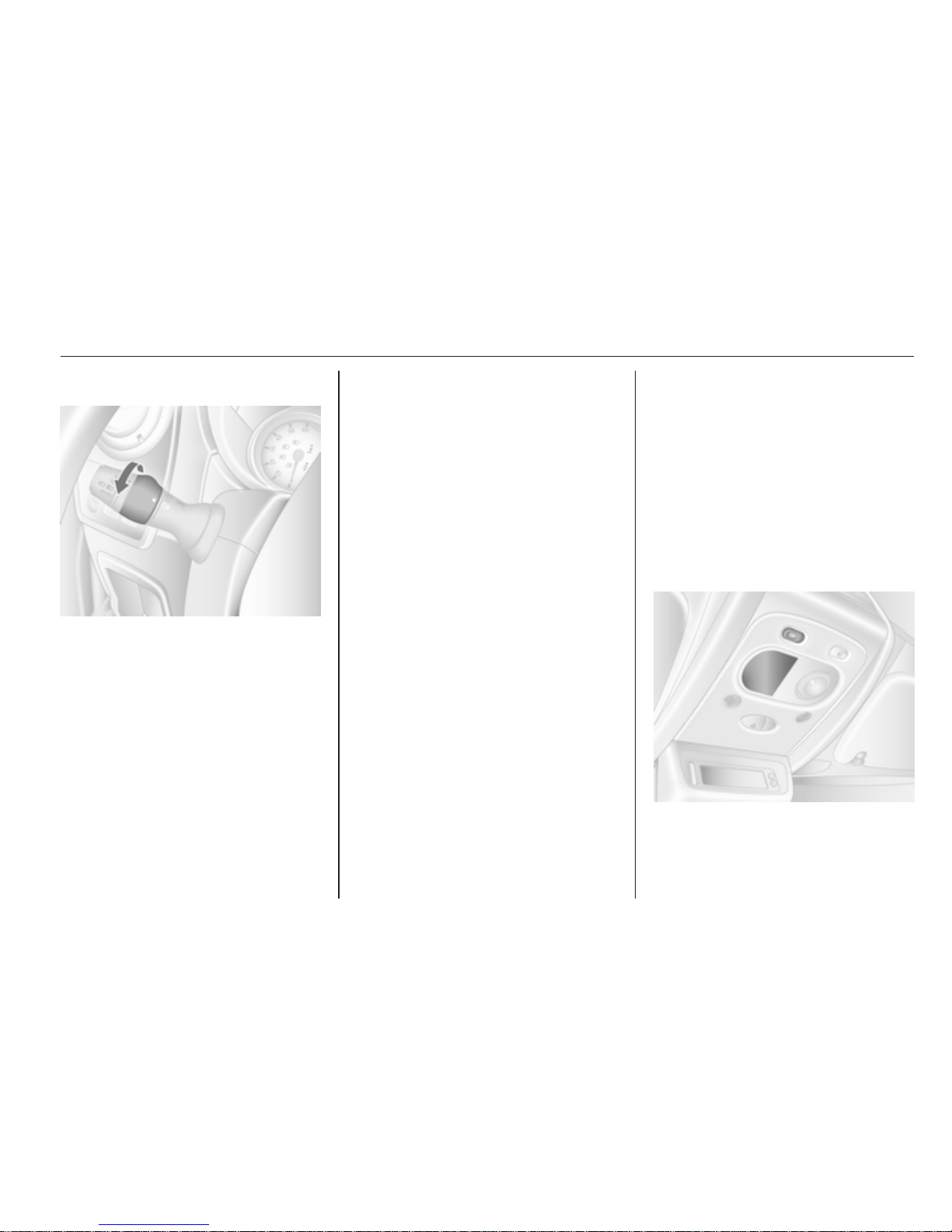
Lighting 79
Rear fog lights
Turn inner switch to position r and
release.
Rear fog lights will only operate when
the ignition and headlights are
switched on.
Reversing lights
The reversing lights come on when
the ignition is on and reverse gear is
selected.
Misted light covers
The inside of the light covers may mist
up briefly in poor, wet and cold
weather conditions, in heavy rain or
after washing. The mist disappears
quickly by itself; to help, switch on the
headlights.
Interior lighting
Interior lights
With the switch in its central position,
the light functions as a courtesy light
and illuminates when the front doors
are opened. Once the front doors are
closed, the courtesy light goes out
after a delay.
Front courtesy light
Operated with the c button.
The interior light extinguishes
immediately when the ignition is
switched on.
Page 80
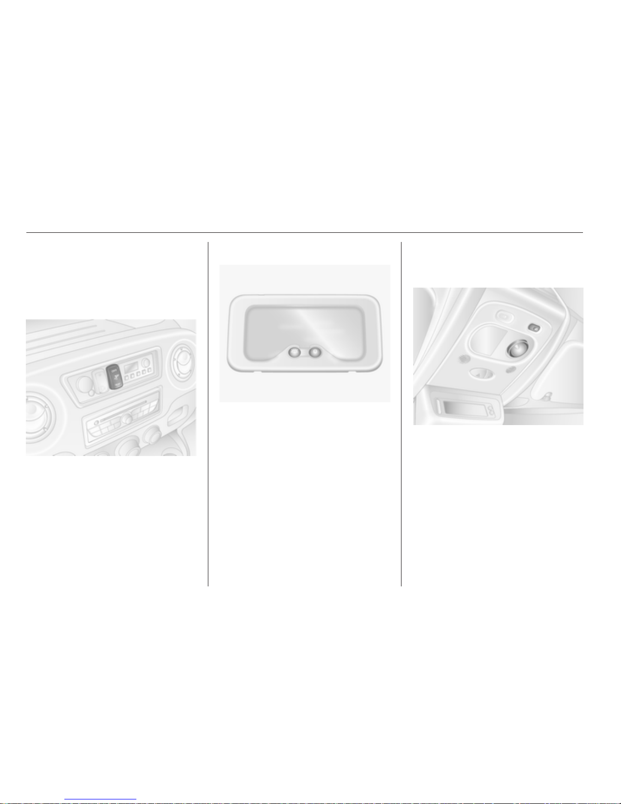
80 Lighting
Rear courtesy lights
Bus
Low level and overhead courtesy
lights are located in the rear
passenger compartment.
Operate rocker switch on the
instrument panel:
press c
= on.
press OFF = off.
Load compartment lighting
Operated by pressing the switch:
■ On constantly
■ Controlled by the function of the
interior light
■ Off constantly
Reading lights
Front reading light
Operated with the l button.
The reading light can be directed as
required.
Page 81
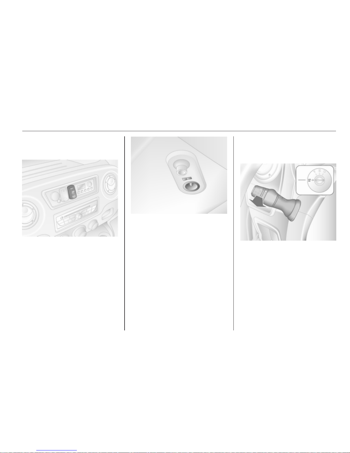
Lighting 81
Rear reading lights
Bus
Operate rocker switch on the
instrument panel:
press l = on.
press OFF = off.
Each reading light can then be
operated individually and directed as
required.
Lighting features
Exit lighting
Headlights come on for approx.
1 minute after the vehicle is parked
and the system is activated.
Activating
1. Switch off ignition.
2. Remove ignition key.
3. Pull turn signal lever towards
steering wheel.
Page 82

82 Lighting
This action can be repeated up to four
times to a maximum period of
4 minutes.
The lighting is turned off immediately
by turning the light switch to any
position and returning to 7.
Page 83
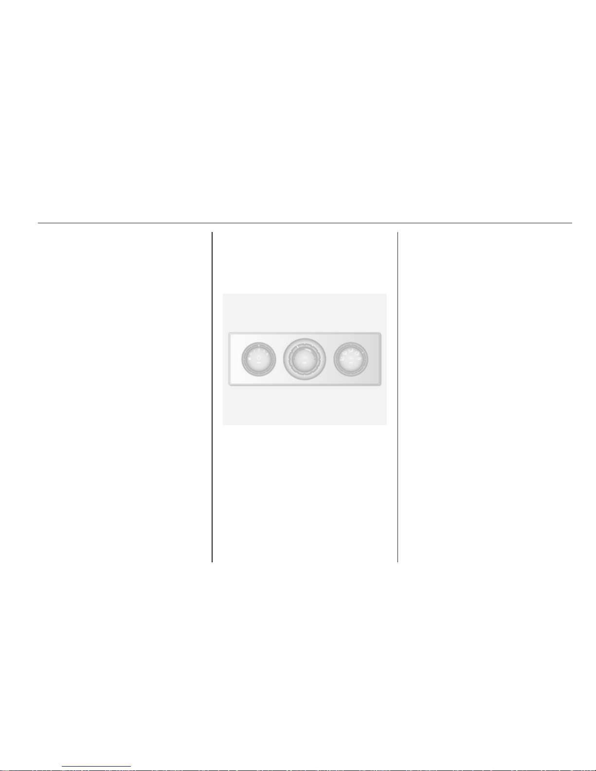
Climate control 83
Climate control
Climate control systems ............... 83
Air vents ....................................... 92
Maintenance ................................ 93
Climate control systems
Heating and ventilation
system
Controls for:
■ Temperature
■ Fan speed
■ Air distribution
Heated rear window Ü 3 28.
Temperature
red = warm
blue = cold
Heating will not be fully effective until
the engine has reached normal
operating temperature.
Fan speed
Adjust the air flow by switching the fan
to the desired speed.
Air distribution
M
= to head area
L
= to head area and foot well
K
= to foot well
J
= to windscreen, front door
windows and foot well
V
= to windscreen and front door
windows
Page 84
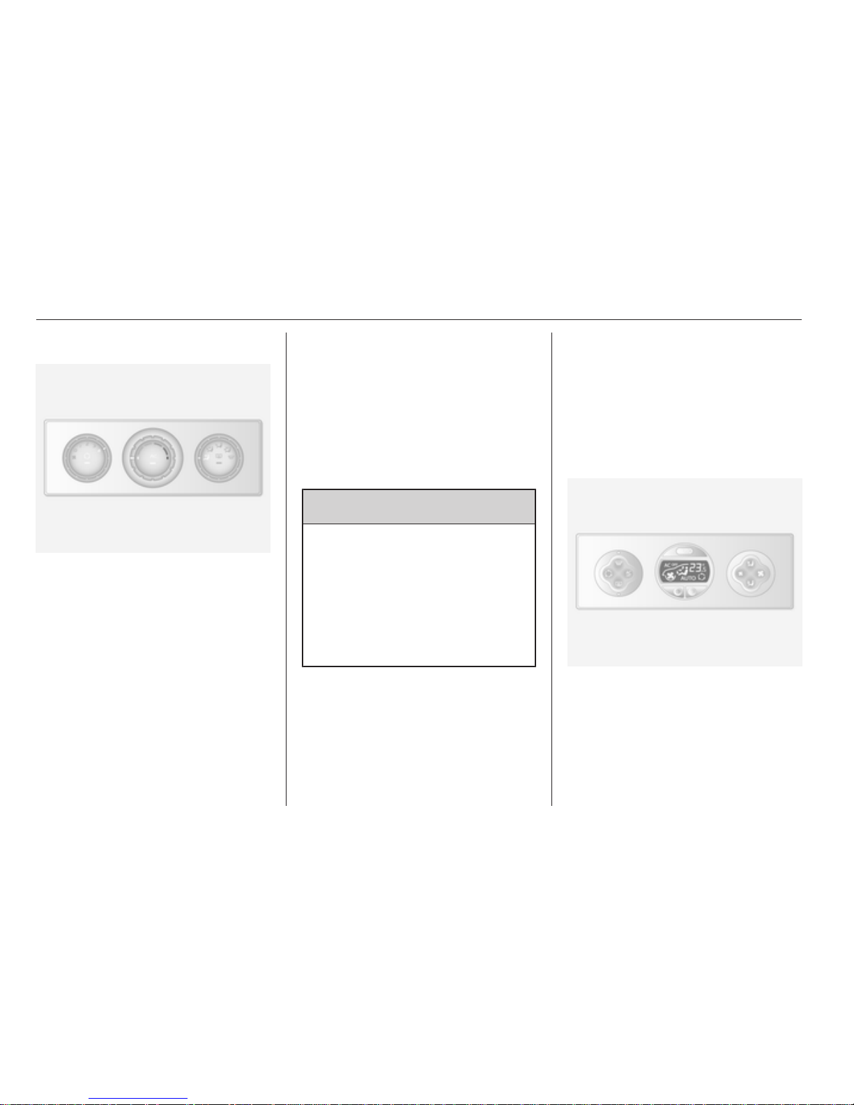
84 Climate control
Air conditioning system
Additional to the heating and
ventilation system, the air
conditioning system has:
AC = cooling
u
= air recirculation
Cooling (AC)
Operated with the AC button and
functional only when the engine and
fan are running.
The air conditioning system cools and
dehumidifies (dries) the air when
outside temperature is a little above
the freezing point. Therefore
condensation may form and drip from
under the vehicle.
If no cooling or drying is required,
switch the cooling system off to save
fuel.
Air recirculation system
Operated with the u button.
9 Warning
The exchange of fresh air is
reduced in air recirculation mode.
In operation without cooling the air
humidity increases, so the
windows may mist up. The quality
of the passenger compartment air
deteriorates, which may cause the
vehicle occupants to feel drowsy.
Maximum cooling
Briefly open the windows so that hot
air can disperse quickly.
■ Cooling AC on.
■ Air recirculation system u on.
■
Set air distribution control to M.
■ Set temperature control to coldest
level.
■ Set fan speed to highest level.
■ Open all air vents.
Electronic climate control
system
Controls for:
■ Temperature
■ Air distribution and menu selection
■ Fan speed
Page 85

Climate control 85
AUTO = Automatic mode
u
= air recirculation
V
= demisting and defrosting
Heated rear window Ü 3 28.
The preselected temperature is
automatically regulated. In the
automatic mode the fan speed and air
distribution automatically regulate the
air flow.
The system can be manually adapted
by use of air distribution and air flow
controls.
The electronic climate control system
is only fully operational when the
engine is running.
For correct operation do not cover the
sensor on the instrument panel.
Automatic mode
Basic setting for maximum comfort:
■ Press AUTO button.
■ Open all air vents.
■ AC on.
■ Set desired temperature.
Temperature preselection
Temperatures can be set to the
desired value.
For reasons of comfort, change
temperature only in small increments.
red = warm
blue = cold
Heating will not be fully effective until
the engine has reached normal
operating temperature.
If the minimum temperature of 15 ℃
is set, the electronic climate control
system runs at maximum cooling.
If the maximum temperature of 27 ℃
is set, the electronic climate control
system runs at maximum heating.
Fan speed
The selected fan speed is indicated
with x in the display.
If the fan is switched off the air
conditioning is also deactivated.
To return to automatic mode: Press
AUTO button.
Demisting and defrosting the
windows
Press the V button.
Temperature and air distribution are
set automatically and the fan runs at
a high speed.
To return to automatic mode: press
button V or AUTO.
Air distribution
Press s or K repeatedly.
Arrows shown in the display indicate
the distribution settings.
Cooling
The air conditioning system cools and
dehumidifies (dries) when outside
temperature is above a specific level.
Therefore condensation may form
and drip from under the vehicle.
If no cooling or drying is required
press AC OFF to switch the cooling
system off, thus saving fuel.
Manual air recirculation mode
Operated with the u button.
Page 86
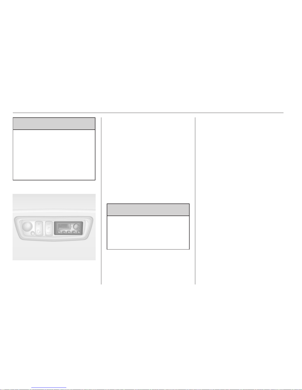
86 Climate control
9 Warning
The exchange of fresh air is
reduced in air recirculation mode.
In operation without cooling the air
humidity increases, so the
windows may mist up. The quality
of the passenger compartment air
deteriorates, which may cause the
vehicle occupants to feel drowsy.
Rear heating system
If the engine is switched off the rear
compartment can be heated by the
additional heating, through low level
vents. By programming values using
the control panel the user can adjust
the time, day and temperature
settings.
Heating will cease to operate if the
vehicle fuel level drops too low.
During operation, power from the
vehicle battery is used. For short
journey times, check the battery
regularly and recharge if necessary.
To ensure efficient performance, the
low level air vents in the rear
passenger compartment must not be
obstructed.
9 Warning
Do not operate the system when
refuelling, when dust or
combustible vapours are present
or in enclosed spaces (e.g.
garage).
Setting the time and day
Press button Ö until the time display
flashes.
If the battery supply has been
interrupted prior to its use press the
m or n button briefly to make the
time display flash.
Adjust the time using the m or n
buttons.
The time is set when the displayed
time stops flashing.
The display for the day will then flash:
adjust the day using the m or n
buttons.
The day is set when the display stops
flashing.
The display will remain illuminated for
approximately 15 seconds after the
ignition is switched off.
Operating and switching of the
rear compartment additional
heating
Press button Y to operate heating. Y
will appear in the display to indicate
that the heating is operating.
Page 87
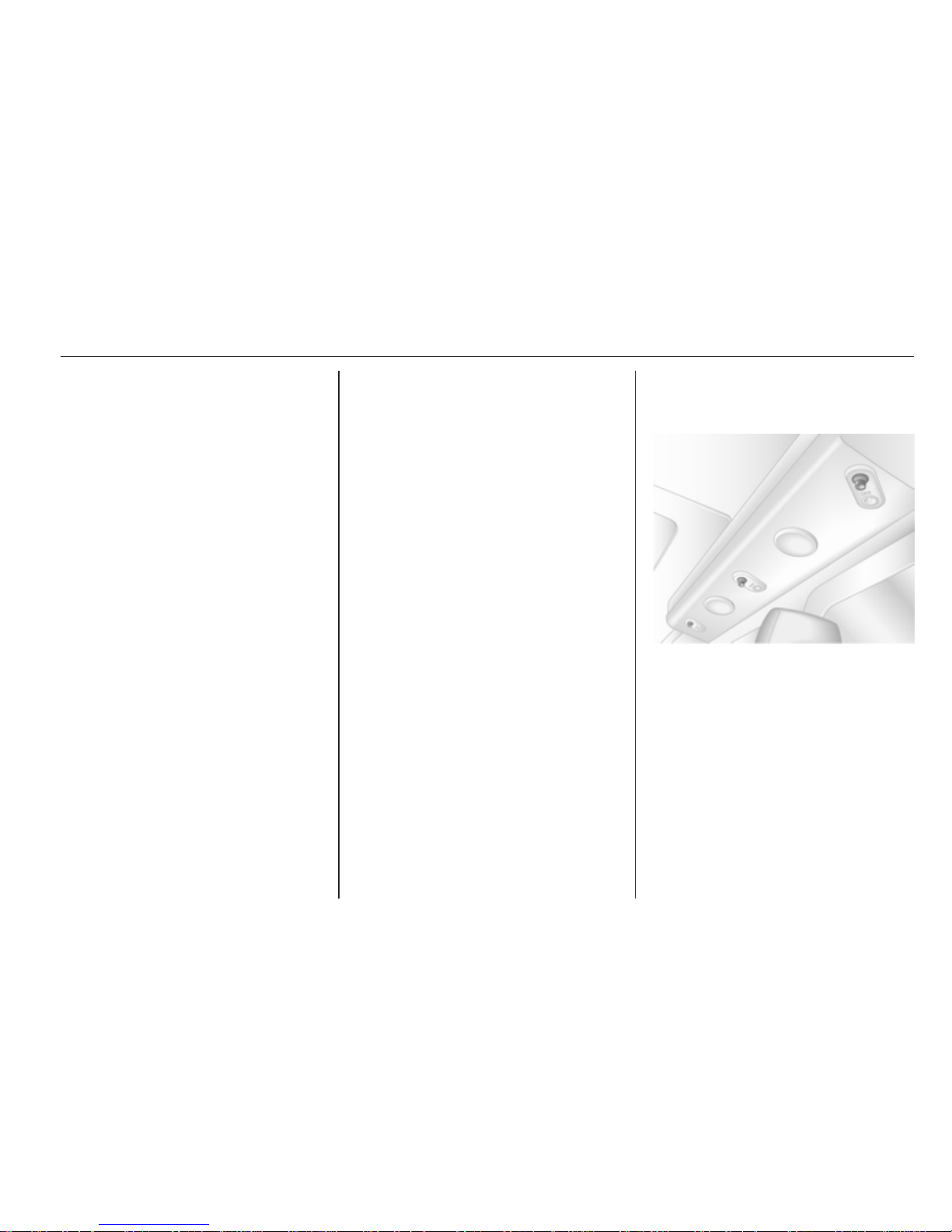
Climate control 87
Changing the period for which
heating is operating
With the heating switched off ( Y
extinguished in display), press m
button for briefly until the period for
which heating is provided flashes in
the display.
Use the m or n buttons to adjust
the heating duration. The duration is
set when the display extinguishes.
Programming the heating mode
It is possible to store up to three
programmes which allow the heating
to be switched on.
Press P button the number of times
for selecting the desired stored
programme.
Press the m or n buttons briefly,
the programming time flashes in the
display.
Using the m or n buttons adjust to
the desired time, as soon as the time
display stops flashing adjust the day
using the m or n buttons.
The time and day are set when the
display stops flashing.
Recalling a programming mode
To activate a stored programme
press P button until the
corresponding number appears on
the display.
Neutral position or no stored
programme activated
Press P button until their is no stored
programme number visible in the
display.
Adjusting the temperature
To adjust the temperature of the
heating turn the rotary knob located
on the control panel.
Turn clockwise = increase
temperature
Turn
anticlockwise
= decrease
temperature
Rear air conditioning
system
The rear air conditioning system is
actuated in conjunction with the front
passenger compartment air
conditioning system.
Bus
Rear air vents
Additional air conditioning is supplied
to the rear passenger compartment
via the overhead air vents.
Page 88
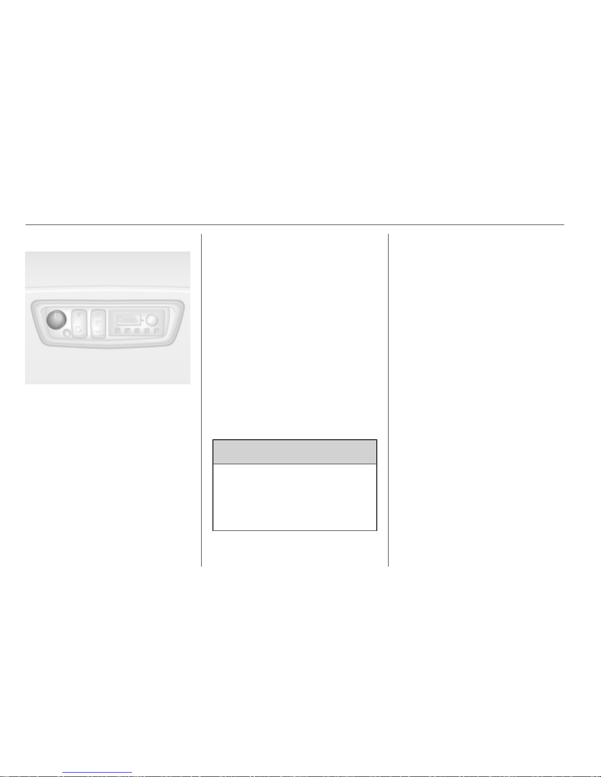
88 Climate control
Fan speed
Adjust the air flow to select the
desired speed.
turn clockwise = increase air flow
turn
anticlockwise
= decrease air flow
Combi
Additional air conditioning is supplied
to the rear passenger compartment
via the air vents located above the
driver and front passenger
compartment.
With the front passenger
compartment air conditioning system
switched on, adjust the air flow to
select the desired speed.
Ensure the air vents are open when in
use to prevent ice forming in the
system.
Auxiliary heater
Coolant heater
The Eberspächer engineindependent, fuel-powered coolant
heater provides rapid heating of the
engine coolant to enable heating of
the vehicle interior without the engine
running.
9 Warning
Do not operate the system when
refuelling, when dust or
combustible vapours are present
or in enclosed spaces (e.g.
garage).
Before starting or programming the
system to start, turn the vehicle's
climate control system to heat and the
air distribution to V.
Switch off when not required. Heating
stops automatically after approx.
2 hours of continuous use, and will
also cease to operate if the vehicle
fuel level drops too low.
During operation, power from the
vehicle battery is used. For short
journey times, check the battery
regularly and recharge if necessary.
To ensure efficient performance,
briefly operate the auxiliary heater
once a month.
Control units
The timer or remote control unit turns
the system on and off, and is used to
programme specific departure times.
Page 89
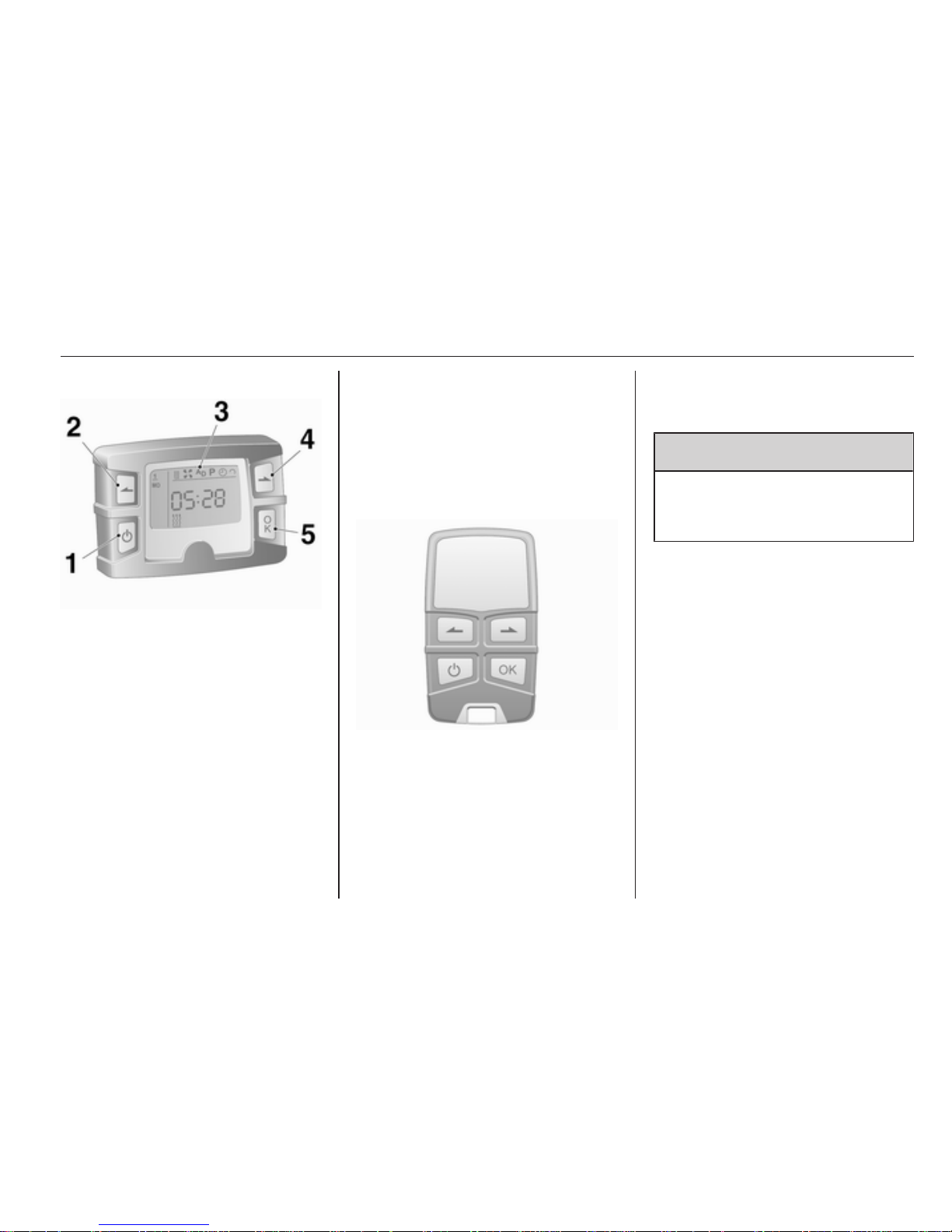
Climate control 89
Timer
1 X
Activation button
= Switches the
control unit on/
off and
changes
displayed
information
2 q Back button = Selects
functions in the
menu bar and
adjusts values
3 Menu bar = Displays the
selectable
functions Y, x,
P, Ö and Y
4 r Next button = Selects
functions in the
menu bar and
adjusts values
5 OK button = Confirms
selection
Remote control
The control buttons operate
identically to the timer unit described
previously.
To activate the remote control, press
activation button X and release it
when the menu bar appears in the
display. The signal indicator and
SENd appear briefly in the display,
followed by the temperature.
9 Warning
When refuelling, switch off the
remote control unit as well as the
heater!
To switch off, press and hold
activation button X to prevent
inadvertent operation.
The remote control has a maximum
range of 600 metres. The range may
be reduced due to environmental
conditions and as the battery
becomes weaker.
Page 90
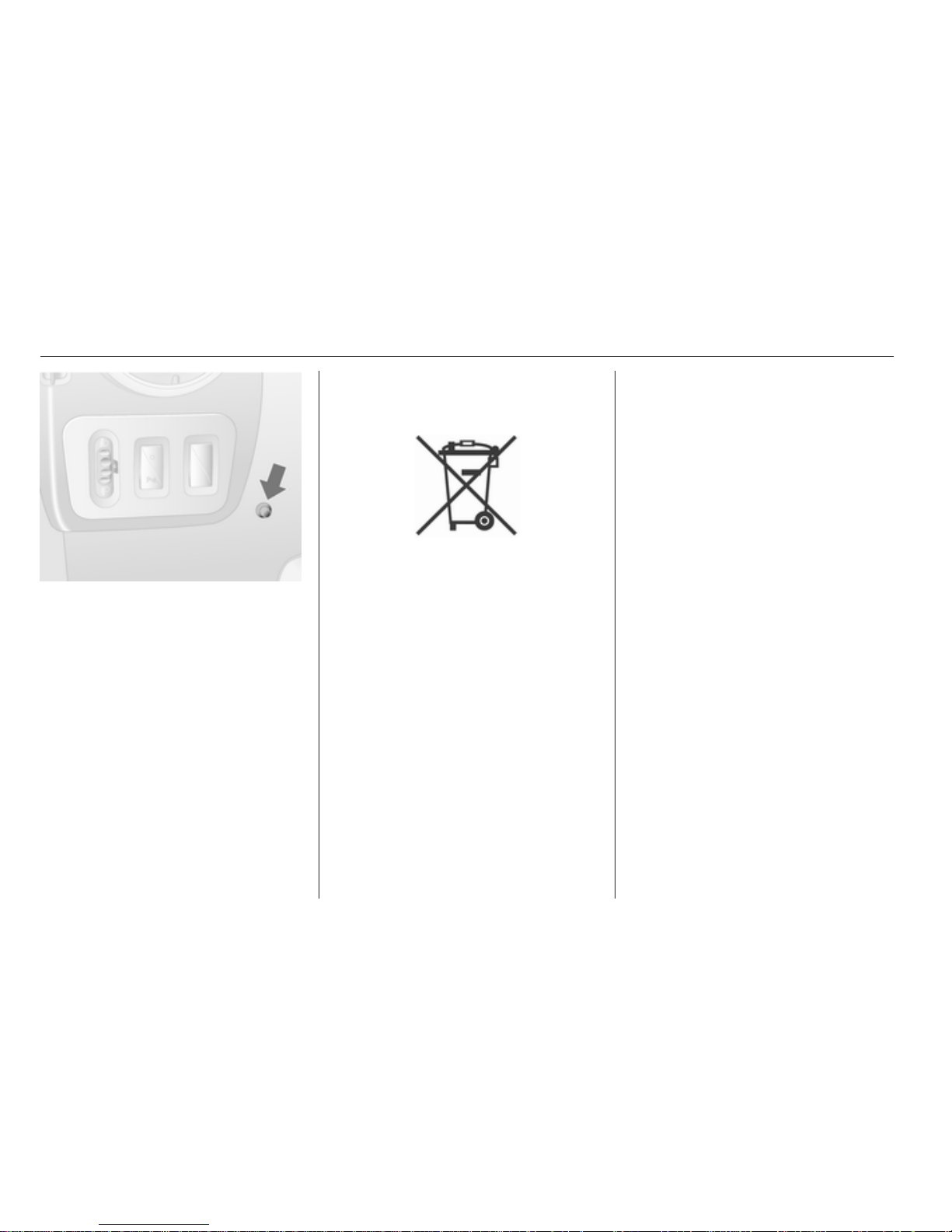
90 Climate control
In addition to the remote control unit,
the heating can also be switched on
for 30 minutes, or off, using the button
on the instrument panel.
Battery replacement
Replace the battery when the range
of the remote control is reduced or
when the battery charge symbol
flashes.
Open the cover using a coin and
replace the battery (CR 2430 or
equivalent), ensuring the new battery
is correctly installed with the positive
(<) side facing the positive terminals.
Replace the cover securely.
Dispose of old batteries in
accordance with environmental
regulations.
Batteries do not belong in household
waste. They must be disposed of at
an appropriate recycling collection
point.
Remote control fault displays
cobA = Poor signal –
adjust position
conP = No signal – move closer
bALo = Battery low –
change battery
Err = System error –
consult workshop
Add,
AddE
= System in learning mode
Teach remote control
If the vehicle battery is reconnected,
the LED in the instrument panel
button illuminates and the system
configures the remote control menu
automatically. If the LED flashes,
press OK button on remote control,
select Add or AddE and confirm.
Additional remote control units may
also be configured. Press the button
until LED flashes, switch on the
remote control, select Add and
confirm.
AddE teaches the current remote
control unit exclusively and blocks all
previously configured units. Add
teaches up to 4 remote control units,
but only one unit can operate the
system at any one time.
Operation
Heating Y
Select Y in the menu bar and confirm.
The predetermined heating duration,
e.g. L 30, flashes in the display.
Page 91

Climate control 91
To temporarily adjust the heating
duration, adjust with the q or r
button and confirm. The value can be
set from 10 to 120 minutes.
To switch off, select Y in the menu bar
again and confirm.
Ventilation x
Select x in the menu bar and confirm.
The ventilation duration can be
accepted or adjusted. The duration
shown is accepted without
confirmation.
To switch off, select x in the menu bar
again and confirm.
Programming P
Up to 3 preset departure times can be
programmed, either during one day or
over one week.
■ Select P in the menu bar and
confirm
■ Select desired preset memory
number 1, 2 or 3 and confirm
■ Select day and confirm
■ Select hour and confirm
■ Select minutes and confirm
■
Select Y or x and confirm
■ If necessary, adjust the runtime
duration prior to departure and
confirm
The next preset memory number to
be activated is underlined and the
weekday is displayed. Repeat the
procedure to programme the other
preset memory numbers.
Pressing button X during the
procedure will exit without storing
programme adjustments.
To delete a preset departure time,
follow the steps for programming until
heating symbol Y flashes. Press
button q or r until oFF appears in
the display and confirm.
Heating stops automatically
5 minutes after the programmed
departure time.
Note
The remote control system features
a temperature sensor which
calculates the runtime according to
the ambient temperature and the
desired heating level (ECO or
HIGH). The system starts
automatically between 5 and
60 minutes prior to the programmed
departure time.
Set weekday, time and heating
duration Ö
If the vehicle battery is disconnected
or its voltage is too low, the unit will
need to be reset.
■
Select Ö and confirm
■ Select weekday and confirm
■ Change hours and confirm
■ Change minutes and confirm
■ Change the default heating
duration and confirm
Heating level Y
The preferred heating level for
programmed departure times can be
set to either ECO or HIGH.
Page 92
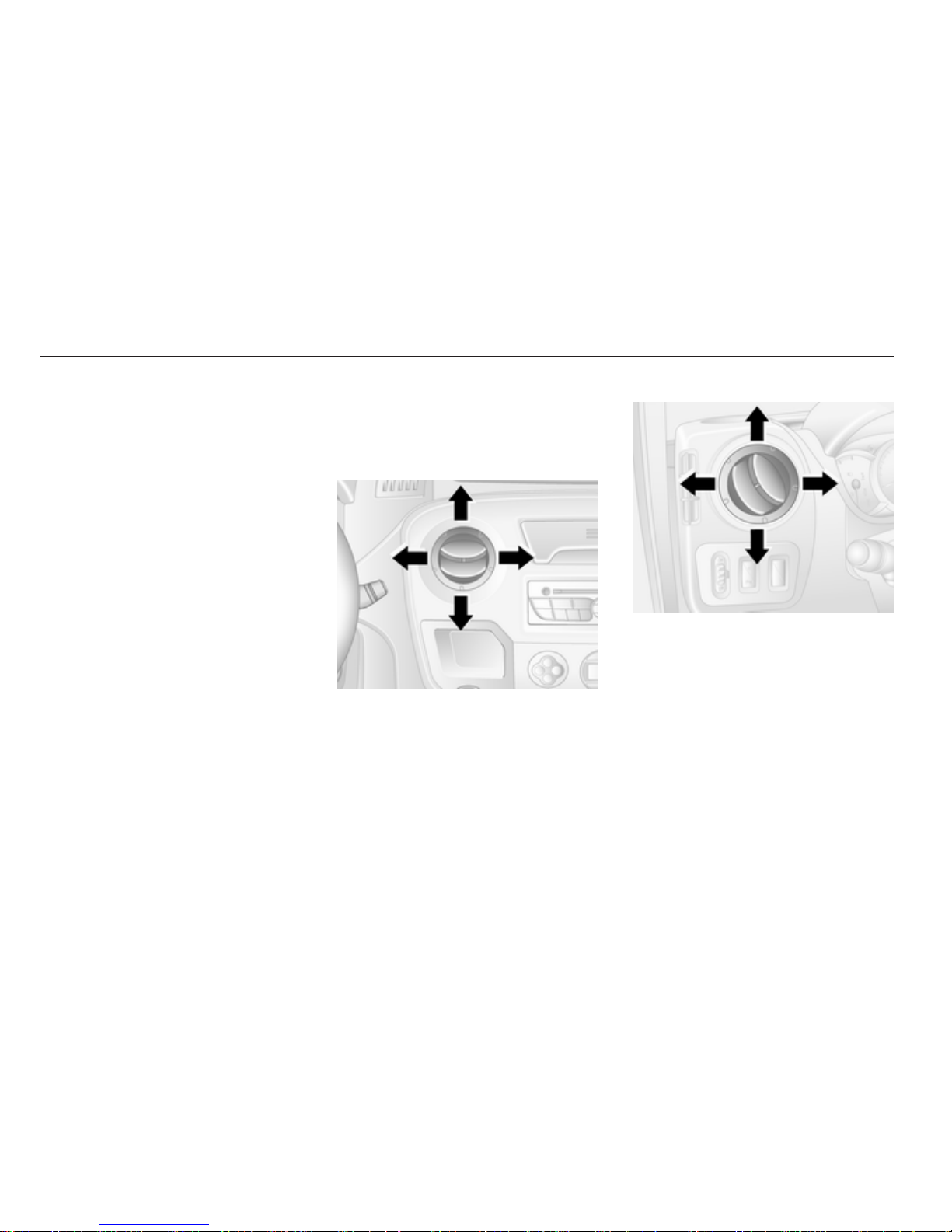
92 Climate control
Select Y and confirm. ECO or HIGH
flashes in the display. Adjust using
the q or r button and confirm.
Air vents
Adjustable air vents
Centre air vents
Press the vent to open.
Direct the flow of air by swivelling the
vent.
Side air vents
Press the vent to open.
Direct the flow of air by swivelling the
vent.
Fixed air vents
Additional air vents are located
beneath the windscreen and door
windows and in the foot wells.
Glovebox cooler
The air conditioning system can also
keep the contents of the glovebox
cool.
Page 93
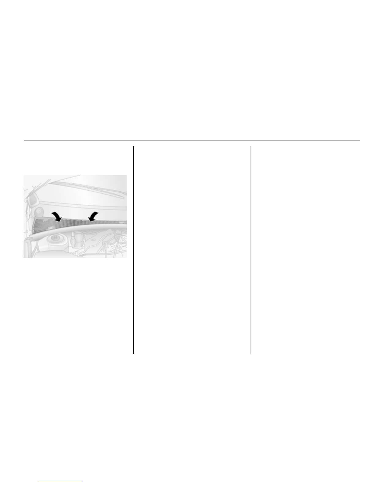
Climate control 93
Maintenance
Air intake
The air intake in front of the
windscreen in the engine
compartment must be kept clear to
allow air intake. Remove any leaves,
dirt or snow.
Pollen filter
The pollen filter cleans dust, soot,
pollen and spores from the air
entering the vehicle through the air
intake.
Air conditioning regular
operation
In order to ensure continuously
efficient performance, cooling must
be operated for a few minutes once
a month, irrespective of the weather
and time of year. Operation with
cooling is not possible when outside
temperature is too low.
Service
For optimal cooling performance, it is
recommended that the climate control
system be checked annually, starting
three years after initial vehicle
registration, including:
■ Functionality and pressure test
■ Heating functionality
■ Leakage check
■ Check of drive belts
■ Cleaning of condenser and
evaporator drainage
■ Performance check
Page 94

94 Driving and operating
Driving and operating
Driving hints ................................. 94
Starting and operating ................. 94
Engine exhaust ............................ 96
Manual transmission .................... 98
Manual transmission
automated .................................... 98
Brakes ........................................ 102
Ride control systems ................. 104
Cruise control ............................. 106
Object detection systems ........... 109
Fuel ............................................ 111
Towing ....................................... 113
Auxiliary features ....................... 114
Driving hints
Control of the vehicle
Never coast with engine not
running
Many systems will not function in this
situation (e.g. brake servo unit, power
steering). Driving in this manner is
a danger to yourself and others.
Pedals
To ensure the pedal travel is
uninhibited, there must be no mats in
the area of the pedals.
Power steering
Never leave the steering wheel on full
lock when the vehicle is stationary as
this may damage the power steering
pump.
Starting and operating
New vehicle running-in
Do not brake unnecessarily hard for
the first few journeys and after new
disc brake pads have been fitted.
During the first drive, smoke may
occur because of wax and oil
evaporating off the exhaust system.
Park the vehicle in the open for
a while after the first drive and avoid
inhaling the fumes.
Do not drive the vehicle
unnecessarily hard or at high engine
speeds during the initial running-in
period.
Fuel and engine oil consumption may
be higher during the running-in
period.
Page 95
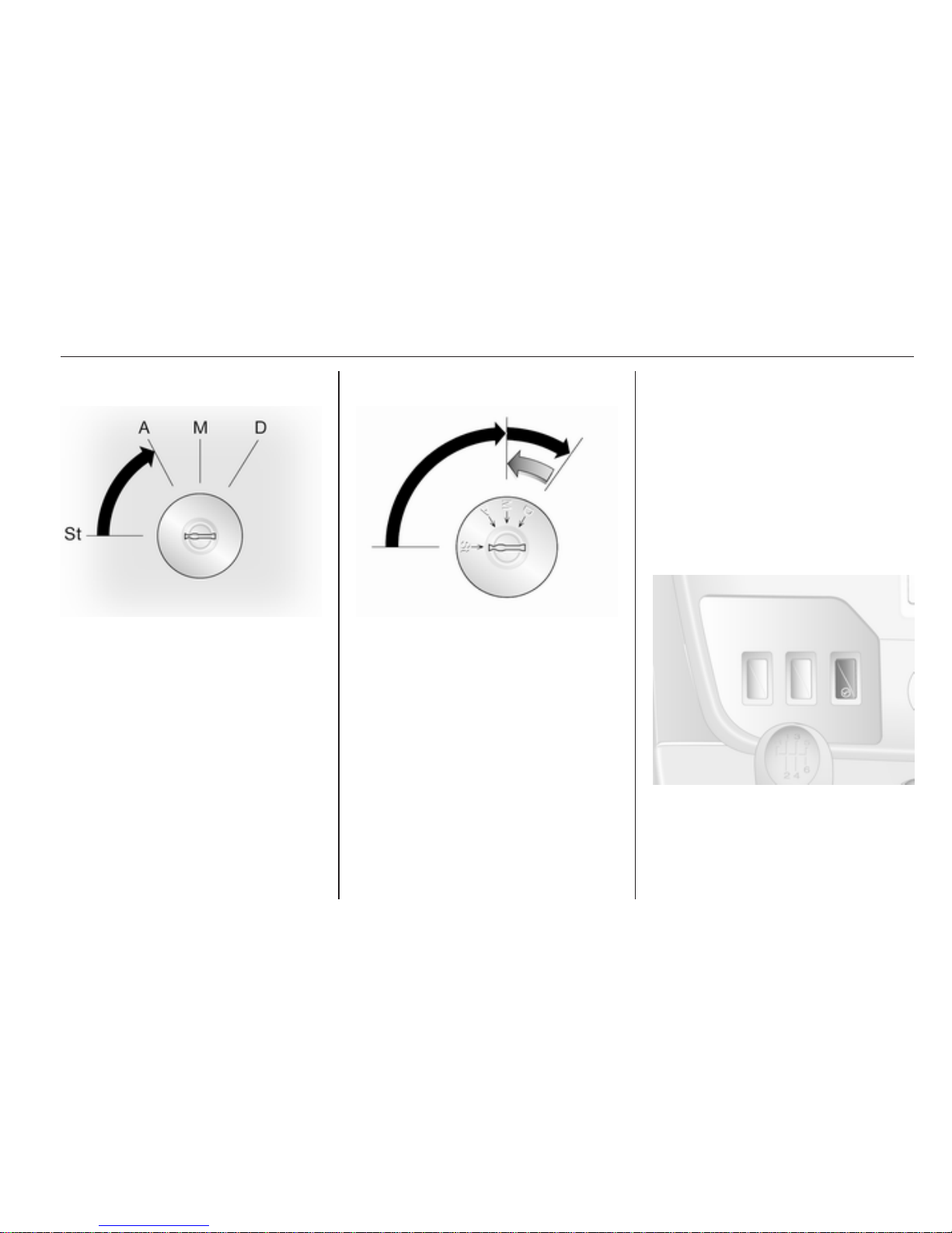
Driving and operating 95
Ignition switch positions
St = Ignition off
A = Steering wheel lock released,
ignition off
M = Ignition on, for diesel engine:
preheating
D = Starting
Starting the engine
Manual transmission: operate clutch.
Manual transmission automated:
operate brake; transmission
automatically shifts to N.
Do not accelerate.
Turn the key to position M for
preheating, until control indicator N
goes out.
Turn key to position D and release.
The increased engine speed
automatically returns to normal idling
speed as the engine temperature
rises.
Start attempts should not last longer
than 15 seconds. If engine does not
start, wait 15 seconds before
repeating starting procedure. If
necessary, depress accelerator
before repeating starting procedure.
Before restarting or to switch off the
engine, turn key back to St.
Idle speed control
To increase the idle speed press the
switch. After a few seconds the
function will be activated.
Page 96

96 Driving and operating
The function will be deactivated
when:
■ The clutch pedal is depressed
■ The accelerator pedal is depressed
■ MTA is not in neutral N
■ Vehicle speed is above 0 km/h
■
Control indicator A, W or C
illuminate in the instrument cluster
To increase or decrease the fast idle
speed rate, consult a workshop.
Overrun cut-off
The fuel supply is automatically cut off
during overrun, i.e. when the vehicle
is driven with a gear engaged but
accelerator is released.
Parking
■ Do not park the vehicle on an easily
ignitable surface. The high
temperature of the exhaust system
could ignite the surface.
■ Always apply parking brake without
pressing release button. Apply as
firmly as possible on a downhill or
uphill slopes. Operate the foot
brake at the same time to reduce
operating force.
■ Switch off the engine and ignition.
Turn the steering wheel until the
steering wheel lock is felt to
engage.
■ If the vehicle is on a level surface or
uphill slope, engage first gear
before switching off the ignition. On
an uphill slope, turn the front
wheels away from the kerb.
If the vehicle is on a downhill slope,
engage reverse gear before
switching off the ignition. Turn the
front wheels towards the kerb.
■ Lock the vehicle and activate the
anti-theft locking system.
Engine exhaust
9 Danger
Engine exhaust gases contain
poisonous carbon monoxide,
which is colourless and odourless
and could be fatal if inhaled.
If exhaust gases enter the interior
of the vehicle, open the windows.
Have the cause of the fault
rectified by a workshop.
Avoid driving with an open load
compartment, otherwise exhaust
gases could enter the vehicle.
Diesel particle filter
The diesel particle filter system filters
harmful soot particles out of the
exhaust gases. The system includes
a self-cleaning function that runs
automatically during driving without
any notification. The filter is cleaned
by periodically burning off the soot
particles at high temperature. This
process takes place automatically at
speeds above 48 km/h and may take
Page 97
Driving and operating 97
up to 30 minutes. Fuel consumption
may be higher during this period. The
emission of smells and smoke during
this process is normal.
Under certain driving conditions, e.g.
short distances, the system cannot
clean itself automatically.
If the cleaning of the filter is required
and if previous driving conditions did
not enable automatic cleaning, it will
be indicated by the illumination of
A in the instrument cluster. Seek the
assistance of a workshop
immediately.
Catalytic converter
The catalytic converter reduces the
amount of harmful substances in the
exhaust gases.
Caution
Fuel grades other than those listed
on page 3 111, 3 154 could
damage the catalytic converter or
electronic components.
Unburnt petrol will overheat and
damage the catalytic converter.
Therefore avoid excessive use of
the starter, running the fuel tank
dry and starting the engine by
pushing or towing.
In the event of misfiring, uneven
engine running, a reduction in engine
performance or other unusual
problems, have the cause of the fault
rectified by a workshop as soon as
possible. In an emergency, driving
can be continued for a short period,
keeping vehicle speed and engine
speed low.
If control indicator Z flashes, the
permitted emission limits may be
exceeded. Lift your foot off the
accelerator until Z stops flashing and
is steadily illuminated. Contact
a workshop immediately.
Malfunction indicator light 3 69.
Page 98
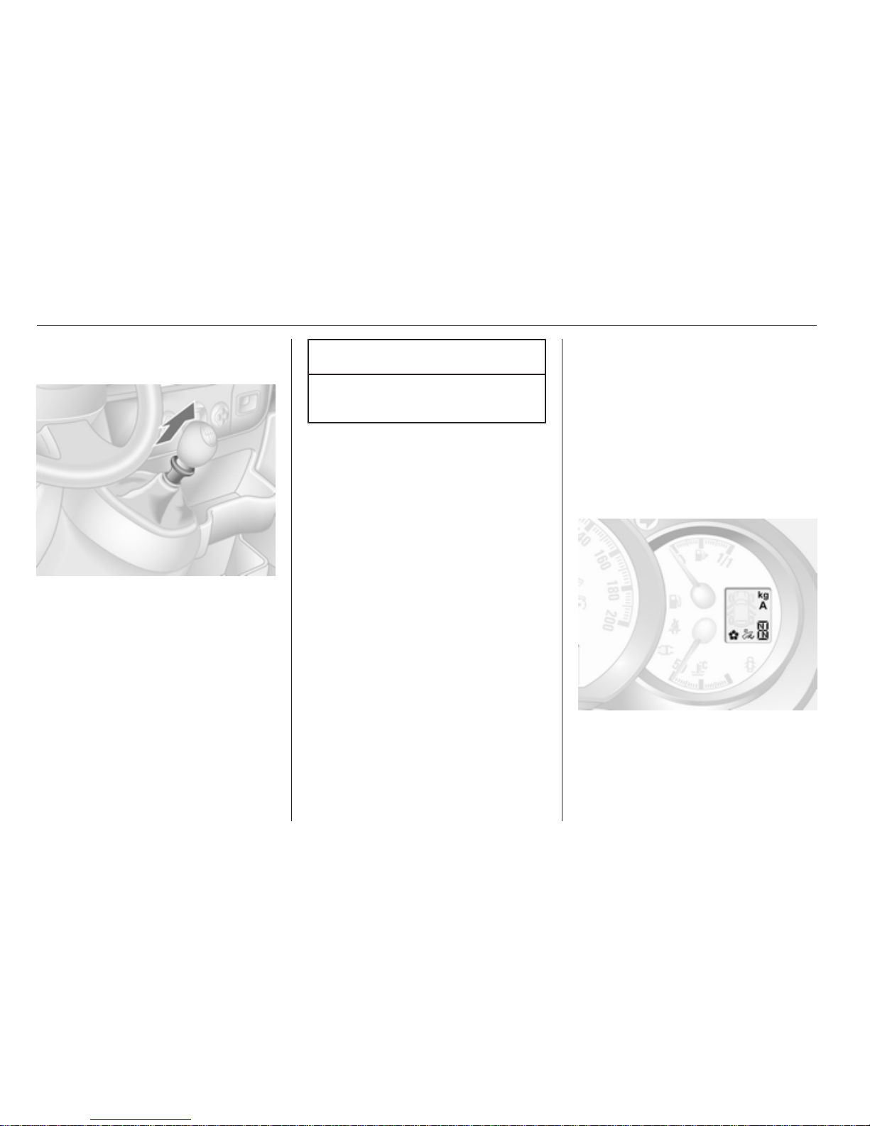
98 Driving and operating
Manual transmission
To engage reverse, with the vehicle
stationary depress the clutch pedal,
pull up the collar on the selector lever
and engage the gear.
If the gear does not engage, set the
lever in neutral, release the clutch
pedal and depress again; then repeat
gear selection.
Do not grind the clutch unnecessarily.
When operating, depress the clutch
pedal completely. Do not use the
pedal as a foot rest.
Caution
It is inadvisable to drive with hand
resting on the selector lever.
Manual transmission
automated
The MTA transmission permits
manual (manual mode) or automatic
gear shifting (automatic mode), both
with automatic clutch control.
Transmission display
Shows the mode and current gear.
Page 99
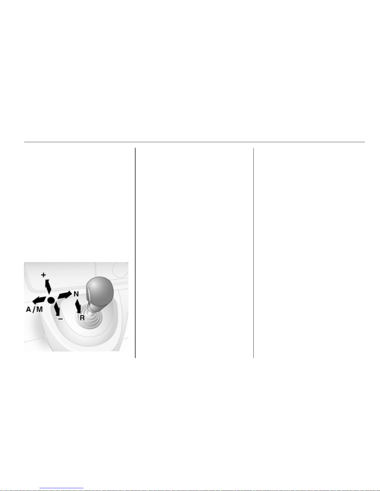
Driving and operating 99
Starting the engine
Depress the foot brake when starting
the engine. If the foot brake is not
depressed, T illuminates in the
transmission display and the engine
cannot be started.
When the foot brake is depressed, the
transmission automatically shifts to
N (neutral); "N" appears in the
transmission display and the engine
can be started. There may be a slight
delay.
Selector lever
Always move the selector lever in the
appropriate direction as far as it will
go. Upon release, it automatically
returns to the centre position.
N = Neutral.
A/M= Switch between automatic
and manual mode.
The transmission display
shows "A" when in automatic
mode.
R = Reverse gear.
Engage only when vehicle is
stationary. The transmission
display shows "R" when
reverse gear is engaged.
+ = Shift to a higher gear.
- = Shift to a lower gear.
Starting off
When the engine is started, the
transmission is in automatic mode.
Depress the foot brake and move the
selector lever towards + to engage 1st
gear.
If R is selected, reverse gear is
engaged. The vehicle starts to move
when the foot brake is released. To
start off quickly, release the foot brake
and accelerate immediately after
engaging a gear.
In automatic mode the transmission
shifts to other gears automatically,
dependent on driving conditions.
To engage manual mode, move the
selector lever towards A/M. The
current gear will appear in the
transmission display.
To engage 1st gear, depress foot
brake and move selector lever
towards + or -. Shift to a higher or
lower gear by moving selector lever to
+ or -. Gears can be skipped by
moving the selector lever repeatedly
at short intervals.
Stopping the vehicle
In automatic or manual mode, first
gear is engaged and the clutch is
released when the vehicle is stopped.
In R, reverse gear remains engaged.
When stopping on gradients, engage
parking brake or depress the foot
brake. To prevent overheating of the
clutch, an intermittent audible
Page 100

100 Driving and operating
warning may sound as a signal to
depress the foot brake or apply the
parking brake.
Switch off engine if stopping for
a lengthy period, e.g. in traffic jams.
Engine braking
Automatic mode
When driving downhill, the manual
transmission automated does not
shift into higher gears until a fairly
high engine speed has been reached.
It shifts down in good time when
braking.
Manual mode
To utilise the engine braking effect,
select a lower gear in good time when
driving downhill.
Rocking the vehicle
Rocking the vehicle is only
permissible if the vehicle is stuck in
sand, mud, snow or a hole. Move the
selector lever between R and A/M (or
between + and -) in a repeat pattern,
while applying light pressure to the
accelerator pedal. Do not race the
engine and avoid sudden
acceleration.
Parking
Apply the parking brake. The most
recently engaged gear (see
transmission display) remains
engaged. With N, no gear is engaged.
When the ignition is switched off, the
transmission no longer responds to
movement of the selector lever.
If the ignition is not switched off, or the
parking brake has not been applied,
an intermittent audible warning will
sound upon opening the driver's door.
Manual mode
If a higher gear is selected when the
engine speed is too low, or a lower
gear when the speed is too high, the
shift is not executed. This prevents
the engine from running at too low or
too high an engine speed.
If engine speed is too low, the
transmission automatically shifts to
a lower gear.
If engine speed is too high, the
transmission only switches to a higher
gear via kickdown.
 Loading...