

Page 1
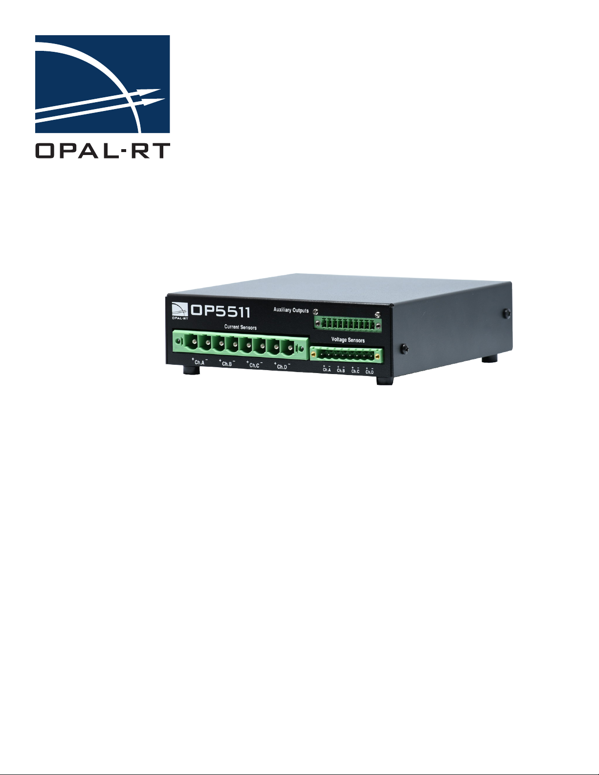
OP5511 User Manual
High Voltage and Current Input
www.opal-rt.com
Conditioning Module
Page 2

OPAL-RT Technologies, Inc. 1751 Richardson, suite 2525 Montreal, Quebec Canada H3K 1G6
© 2017 OPAL-RT Technologies, Inc. All rights reserved
Printed in Canada
Published by
www.opal-rt.com
Page 3

CONTENTS
OP5511 HIGH CURRENT/VOLTAGE MODULE ...................................................................................... 5
INTRODUCTION .................................................................................................................................. 5
DESCRIPTION ..................................................................................................................................... 5
FEATURES ..............................................................................................................................................................5
MECHANICAL INTERFACE ................................................................................................................. 6
CONNECTOR PIN ASSIGNMENTS ..................................................................................................... 7
FRONT CONNECTORS ...............................................................................................................................................7
Current Sensor Pin Assignments .................................................................................................................................... 7
Voltage Sensor Pin Assignments .................................................................................................................................... 7
Auxiliary Outputs Pin Assignments ................................................................................................................................. 8
REAR CONNECTORS .................................................................................................................................................8
DB25 Connector Pin Assignments .................................................................................................................................. 8
Power Connector Pin Assignments ................................................................................................................................. 8
SPECIFICATIONS ................................................................................................................................ 9
SETUP EXAMPLE .............................................................................................................................. 10
OP5511 User Guide OPAL-RT Technologies 3
Page 4

Page 5

OP5511 High Current/Voltage Module
DESCRIPTION
OP5511 HIGH CURRENT/VOLTAGE MODULE
INTRODUCTION
The OP5511, high-current and high-voltage input conditioning module makes it possible to convert 4
current and 4 voltage signals to ±10V voltage level. The current inputs can be factory configured up to
50A continuous. The measured voltage range can be factory configured up to 600V.
Each current and voltage channel has filters that can be used to adjust the bandwidth of the measured
signal input. The bandwith, without filtering, can go up to 100KHz (the default is 70KHz).
This type of module is typically used for monitoring current and voltage on AC or DC motors.
DESCRIPTION
The back panel has activity and out-of-range LEDs for each channel. For current-measurement
channels, the activity LED (green) turns on whenever a current above 200mA is detected, while the
out-of-range LED (red) lights on when the upper current limit of the selected sensor has been reached
(depending on factory jumper setting, the LED will light at 5A, 10A, 15A, 25A or 50A). For voltagemeasurement inputs, the activity LED (green) turns on at 2V, while the out-of-range LED turns on when
the upper voltage limit of the selected range has been reached (depending on factory jumper setting,
the LED will light at 50V, 100V, 200V or 400V).
Although the OP5511 is available as an external unit with appropriate housing, it is primarily used within
existing simulator chassis. Its connectors are the same, regardless of the configuration.
features
• 4 current-measurement inputs, factory configurable from 5A, 15A, 25A up to 50 Amps continuous
(must be specified at time of purchase).
• 4 voltage-measurement inputs: the default voltage range is 600 V. (Also available in 50V, 100V,
200V or 400V; must be specified at time of purchase).
• Rugged screw terminal connections
• Compatible with OPAL-RT OP5340 analog input module
• Activity and out-of-range LEDs for each channel.
• Default bandwidth of 70 KHz (other bandwidths available and must be specified at time of
purchase). See “SPECIFICATIONS” for details
All custom configurations are factory set, therefore voltage and current ranges must be
specified at time of purchase.
OP5511 User Guide OPAL-RT Technologies 5
Page 6
OP5511 High Current/Voltage Module
MECHANICAL INTERFACE
MECHANICAL INTERFACE
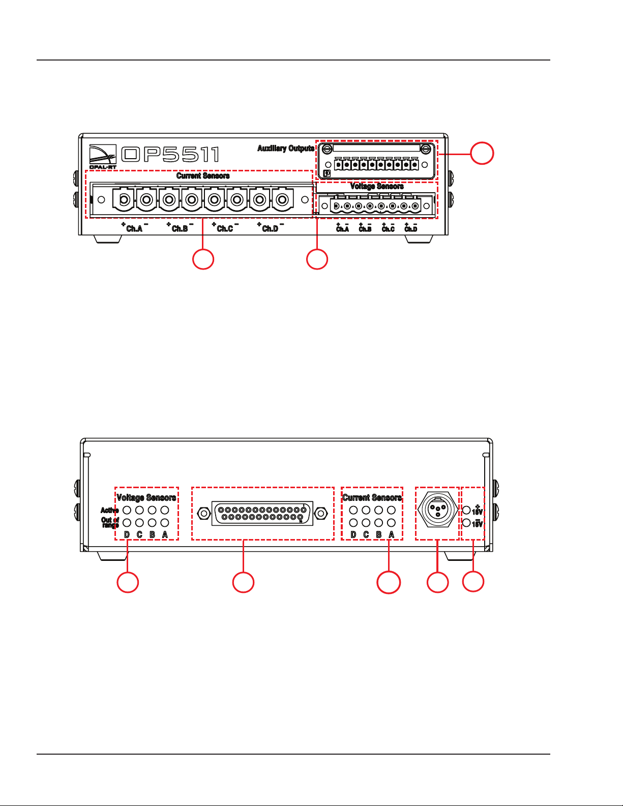
Figure 1 shows the front panel of the module where where voltage and current acquisition and auxiliary
output connectors are located. Table 1, Table 2 and Table 3 provide the connector pin assignments.
C
BA
Figure 1: Front panel connectors
A. Current Sensors connector: connects client device input to be converted to low voltage output.
B. Voltage Sensors connector: connects client device input to be converted to low voltage output.
C. Auxiliary Outputs connector: provides internal connection to reduce the wiring length when both
current and voltage of a motor must be simultaneously sensed. It also allows users to connect the
motor reference voltage to the simulator ground, if required.
Figure 2 shows the rear panel of the module. The DB25 connector (B) is typically connected to an
analog-to-digital converter, such as the OP5340. The conditioning module requires a regulated ±15 volt
power supply to be used. In order to reduce noise, a linear power supply is preferred. Table 4 and Table
5 provide the connector pin assignments.
BA
C
D
E
Figure 2: Rear panel connectors
A. Voltage Sensors LED: Active will light when the minimum voltage is detected. Out of Range will
light when the maximum input voltage is out of range.
B. DB25 connector: allows users to connect to analog output signals
C. Current Sensors LED: Active will light when the minimum current is detected. Out of Range will
light when the maximum input current is out of range.
D. ± 15 VDC power connector
E. Power LEDs indicate when power is functional.
6 OPAL-RT Technologies OP5511 User Guide
Page 7
OP5511 High Current/Voltage Module
Connector PIN ASSIGNMENTS
CONNECTOR PIN ASSIGNMENTS
front connectors
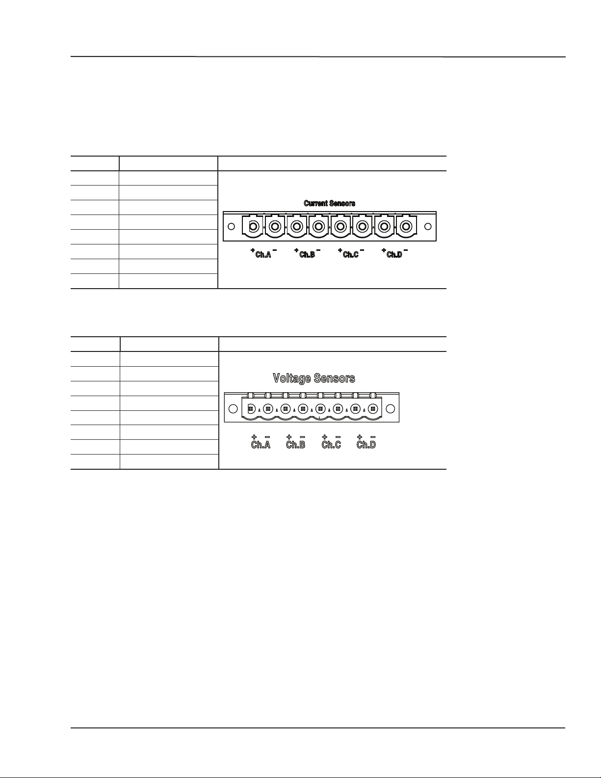
The front panel includes screw terminals to connect the current and voltage inputs.
Current Sensor Pin Assignments
Pin # Description Connector Diagram
1 + Channel A
2 - Channel A
3 + Channel B
4 - Channel B
5 + Channel C
6 - Channel C
7 + Channel D
8 - Channel D
Table 1: Current screw terminal connector
Voltage Sensor Pin Assignments
Pin # Description Connector Diagram
1 + Channel A
2 - Channel A
3 + Channel B
4 - Channel B
5 + Channel C
6 - Channel C
7 + Channel D
8 - Channel D
Table 2: Voltage screw terminal connector
OP5511 User Guide OPAL-RT Technologies 7
Page 8
OP5511 High Current/Voltage Module
1
3
Connector PIN ASSIGNMENTS
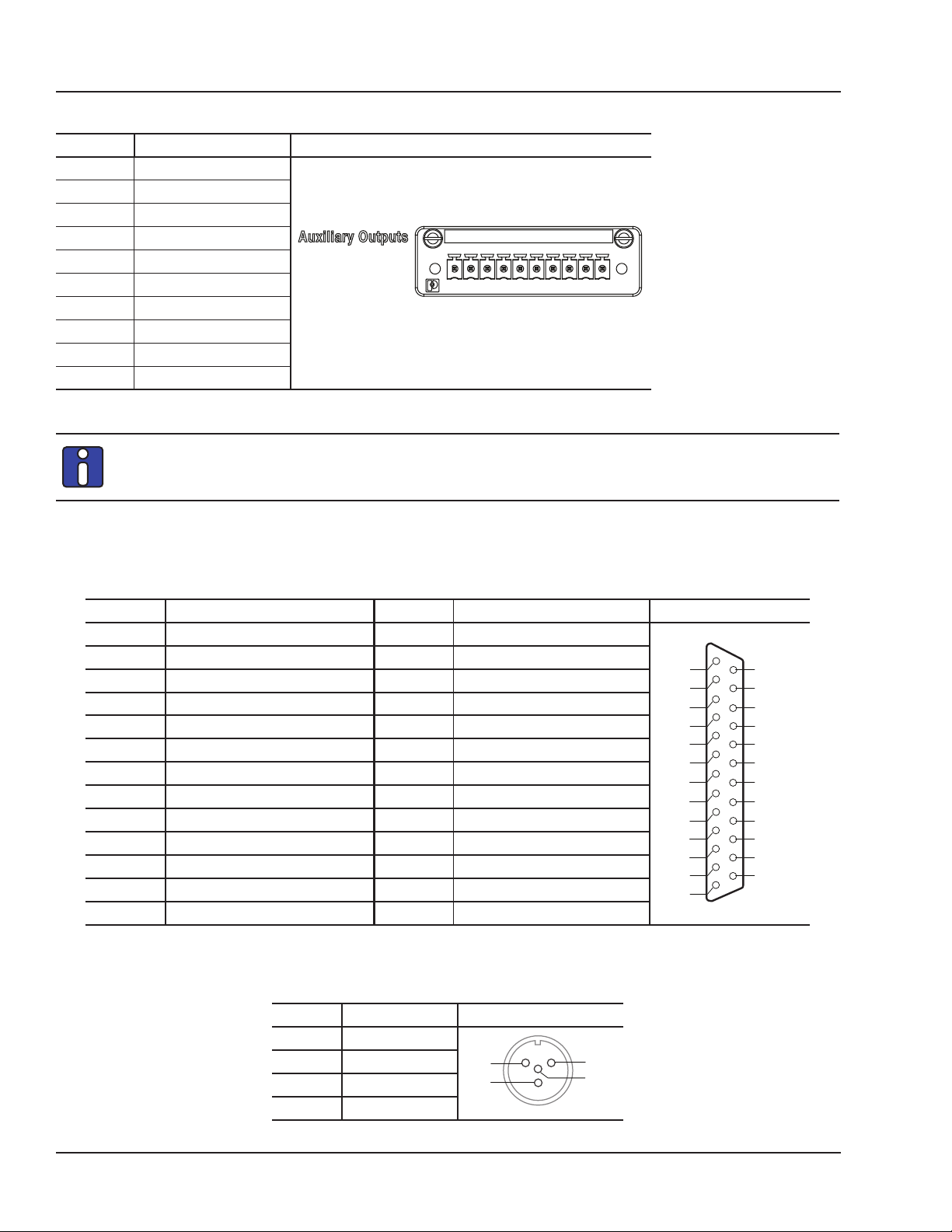
Auxiliary Outputs Pin Assignments
Pin # Description Connector Diagram
1 + IA
2 + IB
3 + IC
4 + ID
5 Vin D
6 Vin C
7 Vin B
8 Vin A
9 GND
10 GND
Table 3: Auxiliary Outputs terminal connector
To minimize connection resistance, it is highly recommended to connect only 1 wire per
screw for the current input pins. If the same pin is needed to provide both current and voltage
measurement in a ground-phase connection , the auxiliary connector must be used.
rear connectors
DB25 Connector Pin Assignments
Pin# Description Pin# Description Connector diagram
1 Ch A Current Sensor Output 14 GND
2 Ch B Current Sensor Output 15 GND
3 Ch C Current Sensor Output 16 GND
4 Ch D Current Sensor Output 17 GND
5 Ch A Voltage Sensor Output 18 GND
6 Ch B Voltage Sensor Output 19 GND
7 Ch C Voltage Sensor Output 20 GND
8 Ch D Voltage Sensor Output 21 GND
9 OPAL-RT technicians use only 22 N/A
10 OPAL-RT technicians use only 23 N/A
11 N/C 24 GND
12 - 15 volts (power) 25 GND
13 + 15 volts (power)
1
2
3
4
5
6
7
8
9
10
11
12
13
Table 4: DB25 connector pin assignments
1
14
14
15
16
17
18
19
20
21
22
23
24
25
25
13
Power Connector Pin Assignments
Pin# Description Connector diagram
1 -15 volts
2 GND
3 +15 volts
4 GND
2
4
Table 5: Power connector pin assignments
8 OPAL-RT Technologies OP5511 User Guide
Page 9

OP5511 High Current/Voltage Module
Connector PIN ASSIGNMENTS
SPECIFICATIONS
Current and voltage sensor ranges must be specified at time of purchase and will be factory configured.
If any adjustments are required, contact OPAL-RT Technical Support.
PRODUCT NAME OP5511
Part number 126-0215 (sensor input board)+ 126-0217 (current/voltage sensor board)
Number of channels 4 voltage channels
4 current channels
Power supply ± 15V
Dimensions 4.57 x 16.60 x 16.35 cm (1.8 in x 6.5 3 x 6.43 in)
Signal conditioning connector DB25F (in from simulator)
Phoenix contact
Operating temperature 10 to 40 ºC (50 to 104ºF)
Storage temperature -55 to 85ºC (-67 to 185ºF)
Relative humidity 10 to 90%, non condensing
Maximum altitude 2,000 m (6562 ft.)
CURRENT SENSOR CHANNEL
Input range factory setting Default 50A (available in 5A, 15A, 25A)
Signal output range ± 10 volts (at full range)
Isolation Galvanic, 2.5 kV
Bandwidth Default 70 kHz ( available in 200Hz, 2kHz, 20kHz or 100kHz without filtering)
VOLTAGE SENSOR CHANNEL
Input range Default 600 V ( available in 50 V, 100 V, 200 V or 400 V)
Signal output range ± 10 volts
Bandwidth Default 70 kHz ( available in 200Hz, 2kHz, 20kHz or 100kHz without filtering)
OP5511 User Guide OPAL-RT Technologies 9
Page 10
OP5511 High Current/Voltage Module
Setup Example
SETUP EXAMPLE
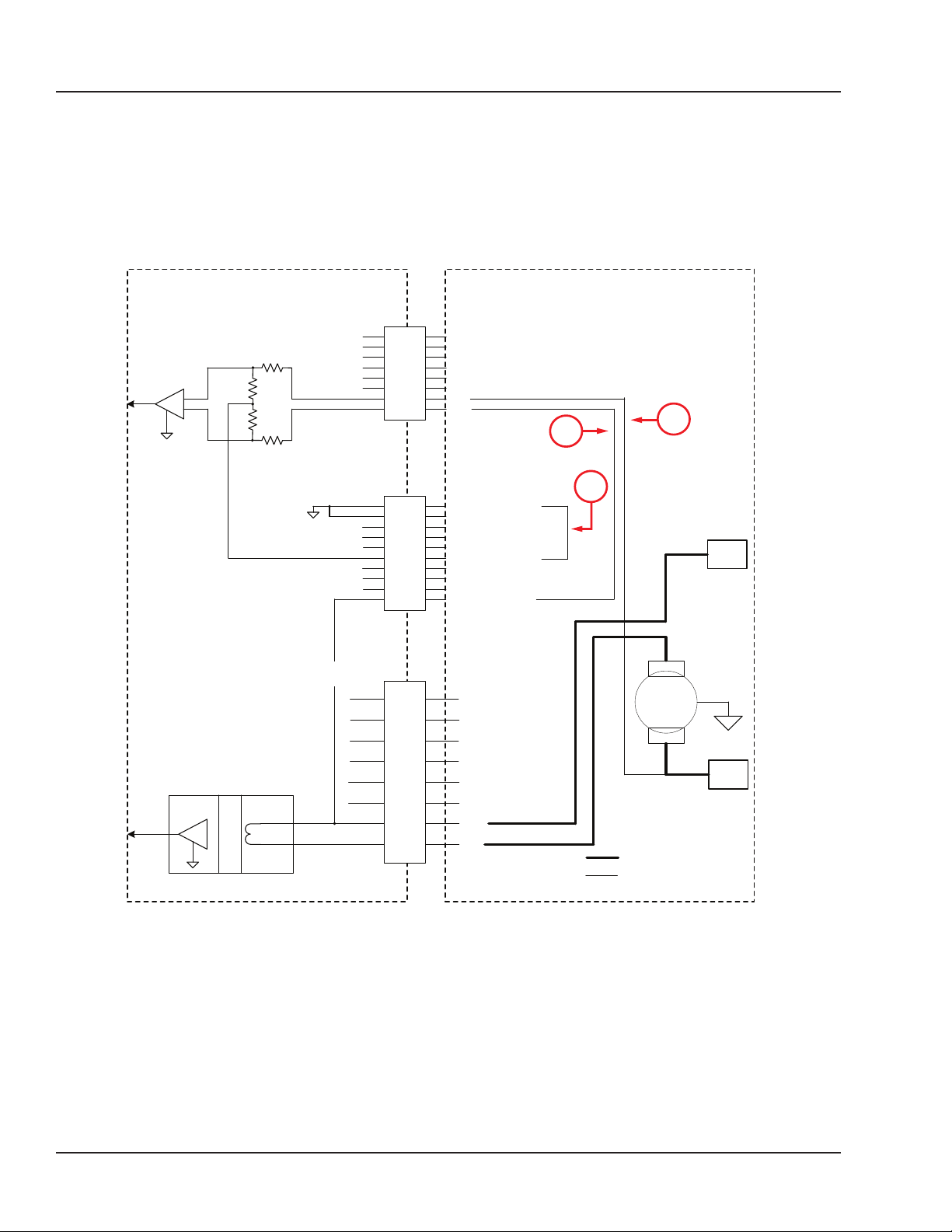
The following diagrams provide an example of current and voltage connections.
To measure the current, the cable must pass through the Ch. A input current removable screw terminal
connector (contact Ch. A+ and contact Ch. A.- )
INTERCONNECTION FOR MEASUREMENT
(Only ONE current channel and ONE VOLTAGE channel represented)
INPUT VOLTAGE J4
connector
VOLTAGE DIVIDER
Ch.D
+
-
Ch.C
+
Ch.B
+
Ch.A
+
2
1
CURRENT SENSOR
ISOLATION
MODULE SIDE
AUXILIARY J5
connector
INPUT CURRENT J3
connector
GND Internal Ground
GND Internal Ground
Ch.D-Voltage
cD
Ch.C-Voltage
cC
Ch.B-Voltage
cB
Ch.A-Voltage
cA
Ch.D-Current
Id
Ch.C-Current
Ic
Ch.B-Current
Ib
Ch.A-Current
Ia
+
Ch.D
-
+
Ch.C
-
+
Ch.B
-
+
Ch.A
-
3
V+
MOTOR
V-
High Current Wire
Low Current Wire
USER SIDE
Figure 3: Measurement setup example
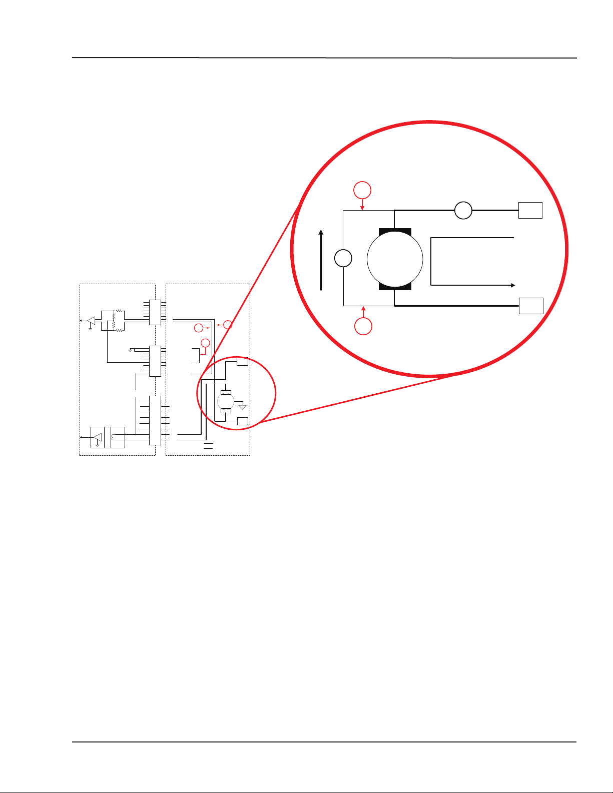
To measure the voltage, only one wire from the motor should be connected to the Ch. A- input voltage
removable screw terminal connector, the other part of voltage Ch. A+ is already available on the
auxiliary connector (internal connection) (1). Make an external wire connection between Auxiliary Ia and
Voltage Ch. A+ (2).
10 OPAL-RT Technologies OP5511 User Guide
Page 11
OP5511 High Current/Voltage Module
Setup Example
If the reference motor voltage has the same ground as the simulator, connect the common point Ch. A
voltage on the auxiliary connector to the simulator ground with an external wire. (3)
Figure 4 provides a closer look at the motor circuit.
INTERCONNECTION FOR MEASUREMENT
(Only ONE current channel and ONE VOLTAGE channel represented)
INPUT VOLTAGE J4
VOLTAGE DIVIDER
CURRENT SENSOR
ISOLATION
MODULE SIDE
connector
AUXILIARY J5
connector
INPUT CURRENT J3
connector
Ch.D
+
Ch.C
+
Ch.B
+
Ch.A
+
GND Internal Ground
GND Internal Ground
Ch.D-Voltage
cD
Ch.C-Voltage
cC
Ch.B-Voltage
cB
Ch.A-Voltage
cA
Ch.D-Current
Id
Ch.C-Current
Ic
Ch.B-Current
Ib
Ch.A-Current
Ia
+
Ch.D
-
+
Ch.C
-
+
Ch.B
-
+
Ch.A
-
2
Ch.A
-
+
A
V+
Input Current Sensor
+
V
Ch.A
-
MOTOR
Input Voltage Sensor
V-
1
2
3
V+
MOTOR
V-
High Current Wire
Low Current Wire
USER SIDE
1
Figure 4: Close up of motor connection example
OP5511 User Guide OPAL-RT Technologies 11
Page 12

CONTACT
OPAL-RT Corporate Headquarters
1751 Richardson, Suite 2525
Montréal, Québec, Canada
H3K 1G6
Tel.: 514-935-2323
Toll free: 1-877-935-2323
Technical Services
www.opal-rt.com/support
Note:
While every effort has been made to ensure
accuracy in this publication, no responsibility
can be accepted for errors or omissions. Data
may change, as well as legislation, and you are
strongly advised to obtain copies of the most
recently issued regulations, standards, and
guidelines.
This publication is not intended to form the
basis of a contract.
UM17-13087 RVN 1.2
03/2017
© OPAL-RT Technologies Inc.
 Loading...