

Page 1
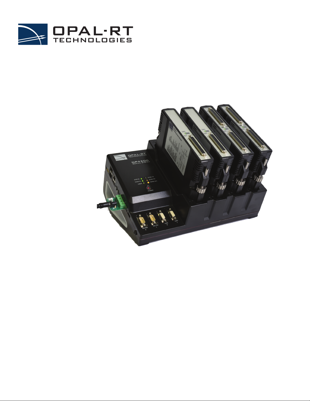
OP4200 RCP/HIL SYSTEM
USER MANUAL
www.opal-rt.com
Page 2

Published by
OPAL-RT Technologies, Inc. 1751 Richardson, suite 2525 Montréal (Québec) Canada H3K 1G6
www.opal-rt.com
© 2018 OPAL-RT Technologies, Inc. All rights reserved
Printed in Canada
Page 3
SYMBOL DEFINITIONS
!
!
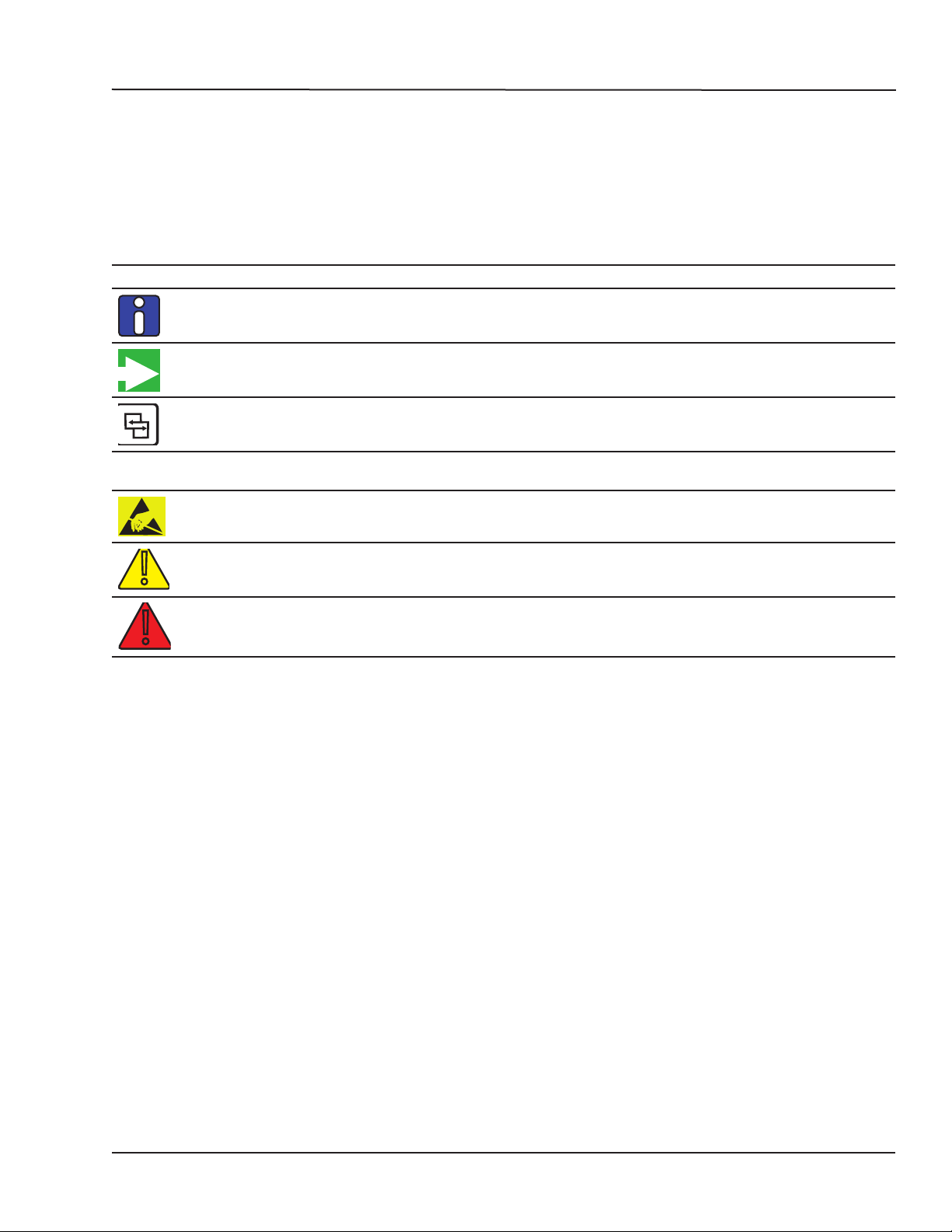
The following table lists the symbols used in this document to denote certain conditions:
Symbol Definition
ATTENTION: Identifies information that requires special consideration
TIP: Identifies advice or hints for the user, often in terms of performing a task
REFERENCE _ INTERNAL: Identifies an additional source of information within the bookset.
CAUTION
Indicates a situation which, if not avoided, may result in equipment or work (data) on the system being
damaged or lost, or may result in the inability to properly operate the process.
Indicates a situation where users must observe precautions for handling electrostatic sensitive devices.
CAUTION: Indicates a potentially hazardous situation which, if not avoided, may result in minor or
moderate injury. It may also be used to alert against unsafe practices.
WARNING: Indicates a potentially hazardous situation which, if not avoided, could result in serious injury or
death.
OP4200 User Manual OPAL-RT Technologies iii
Page 4

Page 5

CONTENTS
DESCRIPTION ......................................................................................................................................... 7
FEATURES .......................................................................................................................................... 7
I/O CONFIGURATIONS ........................................................................................................................ 7
SYSTEM INTERCONNECTION DETAILS ............................................................................................ 8
OP4200 HARDWARE .............................................................................................................................. 9
RECEIVING AND VERIFICATION ........................................................................................................ 9
STANDARD HARDWARE ..................................................................................................................... 9
OptiOnal Hardware ............................................................................................................................................. 9
HARDWARE INTERFACE .................................................................................................................. 10
Side COnneCtOrS ...............................................................................................................................................10
FRONT CONNECTORS ..................................................................................................................... 11
CASSETTES ....................................................................................................................................... 12
CaSSette ledS .................................................................................................................................................12
BASIC INSTALLATION ....................................................................................................................... 13
GENERAL CABLING INSTRUCTIONS .............................................................................................. 13
COnneCt tHe pOwer Cable ............................................................................................................................... 13
COnneCting tHe grOund SCrew .........................................................................................................................14
COnneCting netwOrk Cable ..............................................................................................................................14
INITIAL SETUP ................................................................................................................................... 15
dip SwitCH COnfiguratiOnS ...............................................................................................................................15
CHanging tHe ip addreSS ..................................................................................................................................16
teSting SignalS uSing tHe lOOpbaCk kit ............................................................................................................19
PIN ASSIGNMENTS .......................................................................................................................... 20
TROUBLESHOOTING HARDWARE SETUP ..................................................................................... 21
OP4200 HARDWARE - CASSETTES .................................................................................................... 23
OP4230-1 16 ANALOG OUTPUTS .................................................................................................... 23
featureS ......................................................................................................................................................23
deSCriptiOn ................................................................................................................................................ 23
SCHeMatiCS ..................................................................................................................................................23
tYpiCal appliCatiOnS ...............................................................................................................................24
OP4240-1 16 ANALOG INPUTS ........................................................................................................ 25
featureS ......................................................................................................................................................25
deSCriptiOn ................................................................................................................................................ 25
SCHeMatiCS ..................................................................................................................................................25
OP4242-1 16 ANALOG INPUTS ........................................................................................................ 26
featureS ......................................................................................................................................................26
deSCriptiOn ............................................................................................................................................... 26
SCHeMatiCS ..................................................................................................................................................26
OP4200 User Manual OPAL-RT Technologies 5
Page 6

OP4250-1 32 DIGITAL INPUTS .......................................................................................................... 27
featureS ......................................................................................................................................................27
interfaCeS ..................................................................................................................................................27
tYpiCal appliCatiOnS ...............................................................................................................................28
OP4260-1 32 DIGITAL OUTPUTS ...................................................................................................... 29
featureS ......................................................................................................................................................29
Recommendations ........................................................................................................................................................ 29
OP4200 HARDWARE SPECIFICATIONS ............................................................................................. 30
OP4200 GENERAL SPECIFICATIONS .............................................................................................. 30
Op4230-1 SpeCifiCatiOnS ......................................................................................................................... 31
Op4240-1 SpeCifiCatiOnS ......................................................................................................................... 32
Op4242-1 SpeCifiCatiOnS .......................................................................................................................... 33
Op4250-1 SpeCifiCatiOnS .......................................................................................................................... 34
Op4260-1 SpeCifiCatiOnS .......................................................................................................................... 35
LIMITED WARRANTY ............................................................................................................................ 36
liMited warrantY .....................................................................................................................................36
return pOliCY ............................................................................................................................................36
eXCluSiOnS ..................................................................................................................................................36
warrantY liMitatiOn and eXCluSiOn ..................................................................................................37
diSClaiMer Of unStated warrantieS ................................................................................................ 37
liMitatiOn Of liabilitY .............................................................................................................................37
Page 7
DESCRIPTION
I/O Configurations
DESCRIPTION
The OP4200 is part of the OPAL-RT line of simulation systems. It contains a SoC (system on chip)
integrating an ARM CPU and a Kintex™-7 FPGA, a high-end FPGA, signal conditioning for up to 128
I/O lines and 2 high-speed fiber-optic SFP ports. The design provides four slots for signal conditioning
cassettes.
FEATURES
• 16GB SD card.
• 1024MB DDR3L SDRAM.
• Xilinx Zynq®XC7Z030 all programmable SoC device with Dual-core ARM® Processor Cortex A9
1GHz, Kintex™-7 FPGA, 125K LUT.
• Linux-based real-time operating system.
• 4 cassettes for analog or digital I/O interfaces
• 2 high-speed communication ports
• Communication options: 2 CAN, 2 RS232, 1 Ethernet
I/O CONFIGURATIONS
The OP4200 simulator provides signal conditioning for up to 128 I/Os, which are managed from the PL
(FPGA) section of the Zynq module.
The I/O lines are routed from the Zynq board to the 4 cassettes, through the OP4200’s carrier board.
The swappable cassettes provide signal conditioning flexibility. They are factory configured and their
configuration information is processed by the system at boot time for initialization (I/O line direction,
analog module calibration coefficients, etc.). During initialization, the boot system validates that the
cassette type and position matches the I/O configuration used in the model.
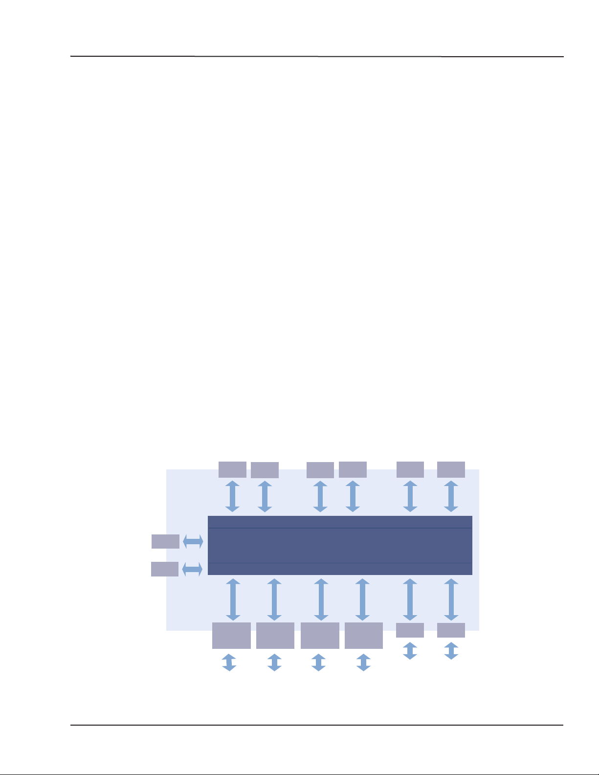
OP4200
JTAG
SYNC
I/O
CASSETTE
1
RS232CAN
RS232CAN
CPU
Zynq 7030 Carrier Board
Zync 7030
I/O
CASSETTE
2
FPGA
I/O
CASSETTE
3
I/O
CASSETTE
4
ETH USB
SFP
SFP
Figure 1: OP4200 system architecture (standard configuration)
OP4200 User Manual OPAL-RT Technologies 7
Page 8

DESCRIPTION
System Interconnection Details
SYSTEM INTERCONNECTION DETAILS
Two SFP sockets are located on the left side if the chassis to allow interconnexion with 3rd-party
devices or with other OPAL-RT chassis. These sockets are connected to the PL section of the Zynq
module and configured by the FPGA programming file (generated using OPAL-RT RT-XSG toolbox).
There are two standard modes of operation available for the SFP ports, both based on the Xilinx Aurora
communication protocol:
• Generic Aurora communication: this mode is enabled using the RT-XSG blockset’s Generic Aurora
blocks in the FPGA programming file’s Simulink model. These blocks are used to exchange
data with 3rd-party devices or with other OPAL-RT systems The data communication layer (data
packing/unpacking) must be configured by the user according to the targeted application. The
communication speed is configurable between 1 and 5 GBps and the SFP transceivers should be
selected accordingly.
• OPAL-RT MUlti-System Expansion link (MUSE)
a network protocol designed by OPAL-RT for inter-system communication. The communication
speed is set to 5Gbps by default, but downgrades automatically to the speed of the other port, if
that port is used at a lower speed for 3rd party device connection.
The MUSE mode is selected in the RT-XSG block by setting the synthesis manager architecture
option to <remote>. In this mode, the unit must be connected to another OPAL-RT system that is
connected in ‘central’ mode, and it then becomes a remote expansion unit (similar to an OP4520 or
OP5607). The simulator ARM CPUs are then used only for monitoring the unit, and not during the
real-time simulation.
1
: this mode encapsulates the Aurora protocol within
1 Restrictions to using MUSE with OPAL-RT Board software architecture may apply depending on your application and software configuration. Please contact
your sales representative or field application engineer to verify compatibility
8 OPAL-RT Technologies OP4200 User Manual
Page 9

OP4200 Hardware
Standard Hardware
OP4200 HARDWARE
RECEIVING AND VERIFICATION
After opening the package, remove the equipment and components. Check all the items described in
“Standard Hardware” and make sure that they are undamaged.
STANDARD HARDWARE
The OP4200 simulator includes the following basic hardware:
Item Description Part Number Qty
OP4200 Hardware chassis with 4 signal conditioning cassettes 429-0101-0094 1
RJ45 cable 305cm (120”) RJ45 cable BLUE T00-0817 1
USB - Serial Cable Includes DB9M-USB A Male,
DB9, F/F, null modem mini type
Converts serial connection to USB to interface OP4200 with computer
Power Supply Desktop AC Adapter 60W 24V
pluggable terminal blocks 4 pos
OP5972 Power jack adapter kit for OP4200 power input 0310-0287
Auxiliary power cable Cable to connect external Vuser supply to digital output cassette from
power jack adapter (OP5972)
Screw terminal board DB37 male slim breakout board (1 per bank of 16 channels) T00-4069 1
Loopback kit Provides access to quick testing and troubleshooting:
Loopback DB37 board
Flat cable
Power cable
T00-0814
T00-0994
T00-4387
T00-0509
0113-0927 1
0126-0361
0113-0737
0113-0799
Table 1: Standard hardware list
Optional Hardware
Item Description Part Number
OP5970 DB37 to Spring cage adaptor 000-126-0556
OP5971 DB37 to SMB adaptor 000-126-0555
OP5973 Mechanical rackmount kit 420-0108-0003
MUSE transceiver Avago AFBR-57R5APZ
MUSE cable LC-LC multimode 850nm optical fiber
1
1
1
(1)
1
OP4200 User Manual OPAL-RT Technologies 9
Page 10
OP4200 Hardware
!
Hardware Interface
HARDWARE INTERFACE
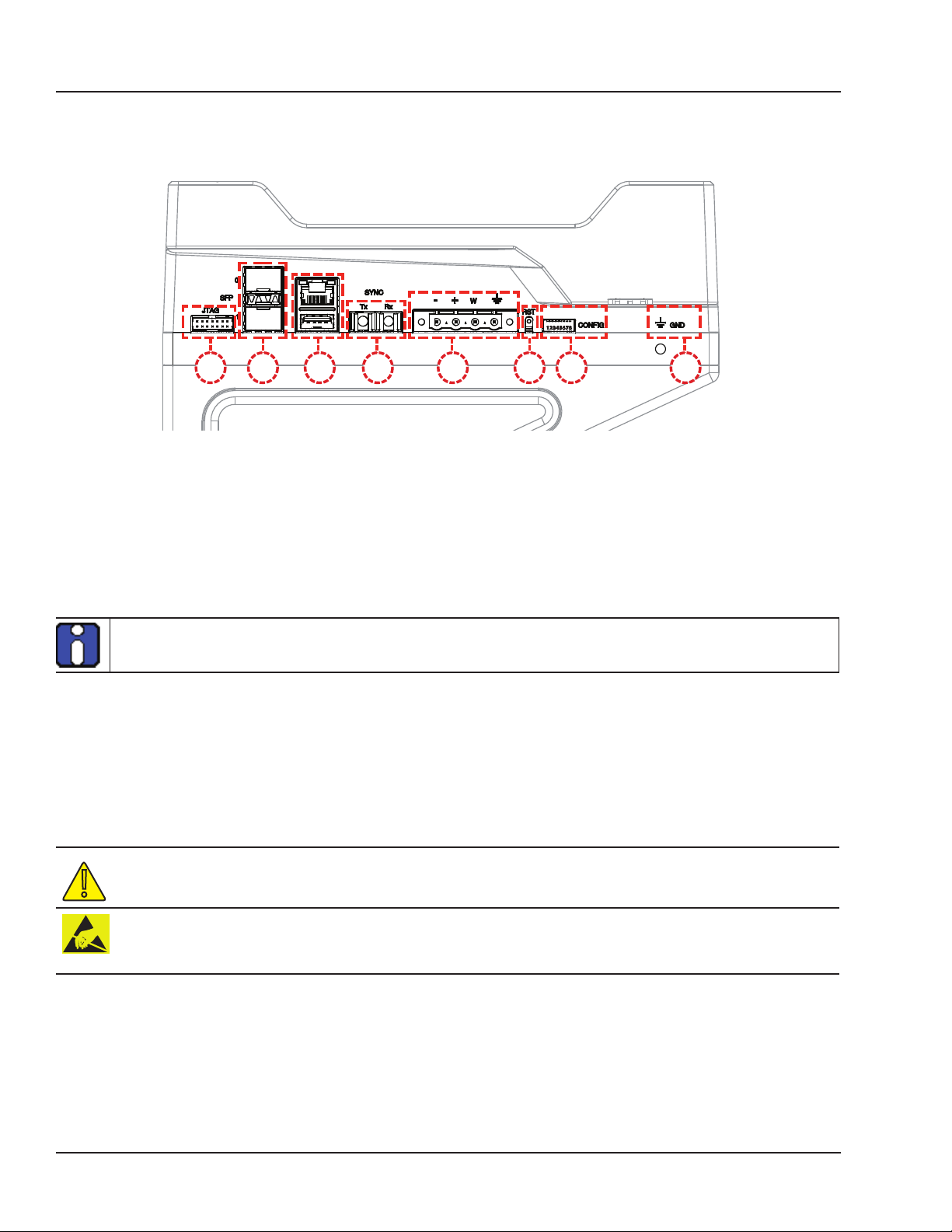
Side Connectors
A
A. JTAG connector for ZYNQ programming (used in the event of lost or damaged configuration, this
feature should only be used by qualified personnel).
B. SFP (small form-factor pluggable) ports controlled from the FPGA, for high-speed communication
with other simulator FPGAs or with third-party devices (see
socket controls one communication link. SFP transceivers and fiber optic cables must be selected
according to the type and speed of the communication protocol implemented in the FPGA (OPALRT MUSE link or 3rd-party device connection).
MUSE link requires specific SFP and cable:
SFP: Avago AFBR-57R5APZ
Cable: LC-LC multimode 850nm optical fiber
C. RJ45 (network connection) and USB 2.0 connector.
D. Fiber optic connectors (Rx and Tx), used to synchronize the OP4200 with other simulators.
E. Phoenix terminal power connector. Can be used with OP5972 power jack adapter kit.
F. Reset button
G. DIP switches: the position of the boot mode switches allow selection of different boot modes for the
processor. (see
H. Ground connector screw: attach grounding wire to nearest ground when using OP4200 in high risk
environments.
“DIP Switch Configurations” for detailed information)
B C D E G HF
Figure 1: OP4200 side connector panel
“CONNECTIVITY” for details). Each
The OP4200 may be subject to EMI when installed in proximity to other devices
OPAL-RT strongly recommends the use of anti-static wrist straps whenever handling any electronic
device provided by OPAL-RT. Damage resulting from electrostatic charges will not be covered by the
manufacturer’s warranty.
10 OPAL-RT Technologies OP4200 User Manual
Page 11
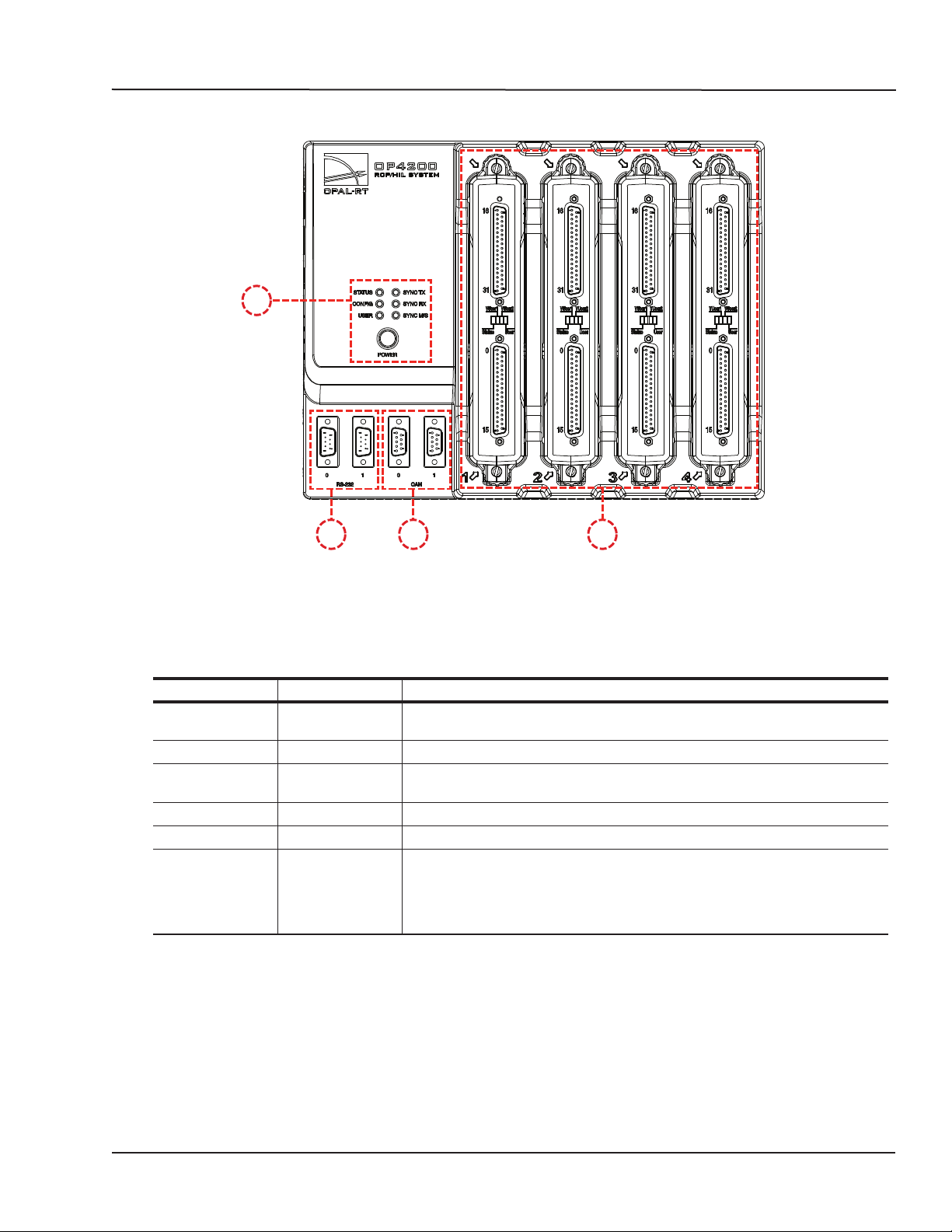
FRONT CONNECTORS
A
OP4200 Hardware
Front Connectors
B C D
Figure 2: OP4200 rear connector panels
A. Function LEDs and Power button
Press the power once to power up the unit. Press twice to shut down. The power button lights when
the unit is powered up and functioning.
There are 6 LED indicators on the housing:
NAME Color Description
STATUS Green
Yellow
CONFIG Green Indicates that FPGA programming is complete.
USER Green
Yellow
SYNC TX Green Lights to indicate when unit transmits a synchronization signal.
SYNC RX Green Lights to indicate when unit receives a synchronization signal.
SYNC M/S* Green
Yellow
B. RS232 connectors. Allow a direct connection to the host computer to display the “OP4200 System
Configuration” IP address modification interface.
C. CAN connectors: CAN 2.0A, 2.0B, and ISO 118981-1 standard compliant
D. I/O cassettes (see “Cassettes” for more details).
Indicates that the unit is powered up and functioning properly
Indicates a system error
User configurable to display a condition specified by the user. If undefined,
displays no status.
Lights yellow (at startup) when no model is loaded. Once a model is loaded:
Indicates that the unit is in Master mode.
Indicates that the unit is in Slave mode mode (the “Use external
synchronization source” checkbox in OPAL-RT Board driver via allows the
user to make the unit a slave)
OP4200 User Manual OPAL-RT Technologies 11
Page 12

OP4200 Hardware
Cassettes
CASSETTES
There are 4 cassettes slots, labeled 1 to 4, in the OP4200. The OP4200 standard configuration includes
the following four cassettes:
Slot 1: OP4240-1, 16 analog inputs
Slot 2: OP4230-1, 16 analog outputs
Slot 3: OP4250-1, 32 digital inputs
Slot 4: OP4260-1, 32 digital outputs.
See the sections specific to each cassette for conditioning details.
Digital cassettes have two DB37 connectors (one for channels 00-15 and one for channels 16-31), and
analog cassettes have one DB37 connector (for channels 00-15).
Cassette LEDs
Each cassette has 4 LEDs, each used to indicate a specific status:
LED # NAME DESCRIPTION
1
Status Blinking green: FPGA and hardware functioning normally.
2
VUser1
(digital only)
3
VUser2
(digital only)
4
User NOT USED
Blinking red: FPGA not responding, not sending heartbeat signal to cassette.
Off: hardware malfunction in cassette.
Green = external Vuser present
Red = no external Vuser present
Green = Vuser present
Red = no Vuser present
12 OPAL-RT Technologies OP4200 User Manual
Page 13
OP4200 Hardware
!
!
!
General Cabling Instructions
HARDWARE INSTALLATION
BASIC INSTALLATION
Follow this simple installation procedure. Make sure to respect proper grounding,
1. Place the OP4200 on a shelf or desktop.
2. Connect the power cable to the nearest power outlet
3. If using in high risk tests or environment, connect the ground screw as described in the
“Connecting Network Cable” section below
4. Connect the RJ45 cable from the OP4200 to a network jack.
OPAL-RT strongly recommends the use of anti-static wrist straps whenever handling any electronic
device provided by OPAL-RT. Damage resulting from electrostatic charges will not be covered by the
manufacturer’s warranty.
Disconnect power before servicing.
The OP4200 may be subjected to EMI when installed in proximity to other devices. Make sure to
connect the OP4200 to the nearest ground to prevent any EMI related damage to the simulator.
GENERAL CABLING INSTRUCTIONS
The OP4200 provides a number of connectors that each allow users a specific interaction with the
unit. Some connections are necessary to operate the OP4200, while others provide optional features
and interactions. This section presents the necessary connections first, then provides instructions for
optional connections.
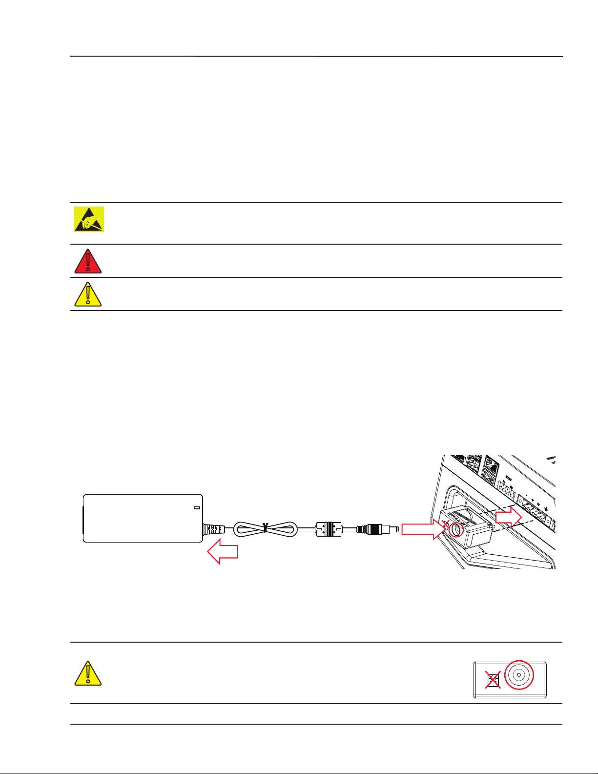
Connect the Power Cable
The power cable is connected to the OP4200 using a special adaptor (OP5972).
POW ER LED
1
2
3
Figure 3: Connecting the power cable
1. Press the power adapter box firmly into the phoenix connector on the OP4200
2. Insert power supply connector into adapter box, as shown.
3. Plug power cable into appropriate source (outlet).
Do not insert the power cord into the Vuser 24V output (square connector
on OP5972 power jack adapter). This may damage all connected devices.
Make sure to insert the power cord connector into the round connector on
the power jack adapter
OP4200 User Manual OPAL-RT Technologies 13
Vuser 24V
output
connector
Power input connector
Page 14
OP4200 Hardware
General Cabling Instructions
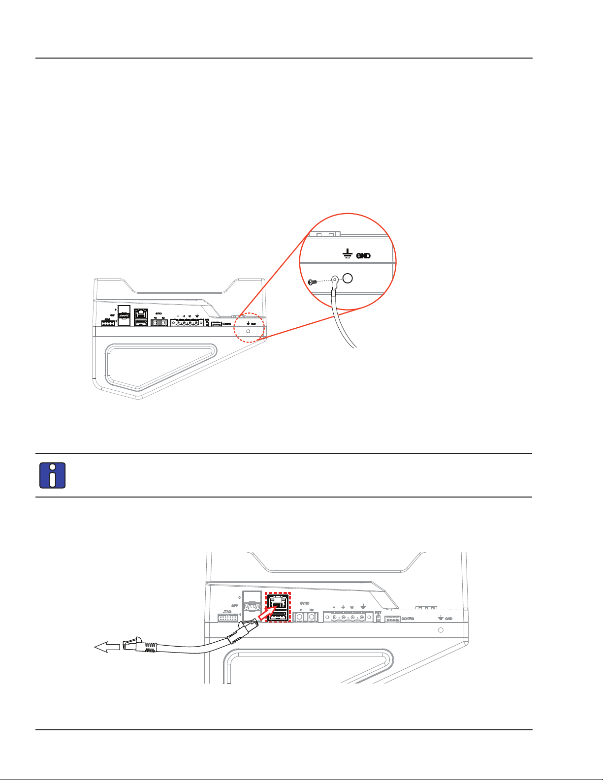
Connecting the Ground Screw
If you are working on high risk tests or in a high risk environment, you should connect a grounding
cable from the OP4200 ground screw to ensure that it terminates securely in a ground. Proper
grounding will help to prevent electric shocks, protect the OP4200 from voltage spikes (from a variety of
causes, including lightning strikes), and provide increased immunity from EMI by lowering noise levels
and emissions.
• Select a flat braided grounding strap of adequate length (as short as possible provides best
protection), with ring terminals on each end.
• Attach one ring terminal to the ground screw on the OP4200 (shown in Figure 4).
• Attach the other ring terminal to the nearest ground source using a nut and lockwasher.
Figure 4: Connecting the OP4200 to the ground
Connecting Network Cable
Before connecting your OP4200 to your network, verify the IP address with your IT
department. You may need to change the simulator IP address to correspond to available
addresses on your network. See
The OP4200 simulator offers quick, single-ended connections, through RJ45. The network cable must
only be connected to the standard network jack. DO NOT plug the network cable into any jack other
than the jack intended for that purpose.
To network
“Changing the IP Address” for instructions.
To OP4200
Figure 5: Connecting network cable
14 OPAL-RT Technologies OP4200 User Manual
Page 15
OP4200 Hardware
Initial Setup
INITIAL SETUP
Although the OP4200 is configured to function right out of the package, there are a few configurations
that may be necessary (or desired) based on your network setup or according to your specific
parameters. This section deals with how to modify those parameters before you proceed to using your
OP4200.
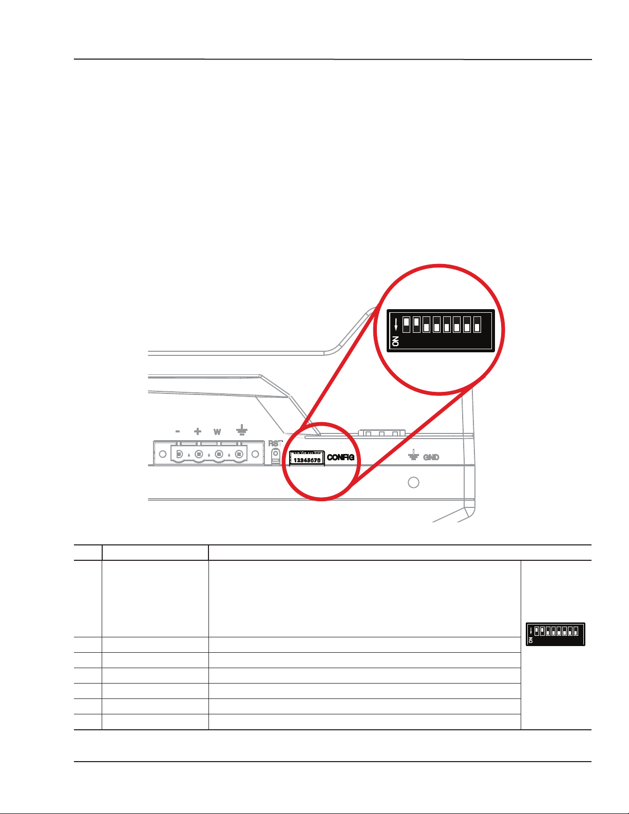
DIP Switch Configurations
This feature should be reserved for qualified OPAL-RT personnel.
DIP switches on the OP4200 make it possible to set various boot and operation parameters.
After a Reset, the boot mode switches are read to determine the primary boot device used (default
mode is boot from SD card).
1 2 3 4 5 6 7 8
Figure 6: DIP Switch
SW # Description Functionality
1/2 Boot mode 0/1 Used in conjunction with switch #2, this selects the device to read at boot:
Boot Device Boot Mode 1 Boot Mode 0
JTAG ON ON
NAND ON OFF
QSPI OFF ON
uSD Card OFF OFF (default position)
3 Console Enable Service When set to ON, RS232 port 0 is set in terminal mode
4 N/A NOT USED
5 CAN1 Termination When set to ON the 120 ohm CAN termination is enabled for CAN port 0
6 CAN2 Termination When set to ON the 120 ohm CAN termination is enabled for CAN port 1
7 N/A NOT USED
8 N/A NOT USED
1 2 3 4 5 6 7 8
ON = down,
Off = up
OP4200 User Manual OPAL-RT Technologies 15
Page 16
OP4200 Hardware
Initial Setup
Changing the IP Address
The OP4200 pre-configured with an IP address (an identifying label will be attached to the unit), but it
may conflict with your network insfrastructure; you may need to change the IP address for your OP4200.
The best way to do this is to directly connect your OP4200 to your host computer (laptop, etc.). (Be sure
to contact your IT department to obtain a valid IP address from them).
Before you begin, make sure your computer has a serial terminal program installed; you will need it to
access the “OP4200 Recovery” application. If there is no serial terminal installed, you must install one
(such as MobaXterm) to access the OP4200 configuration application.
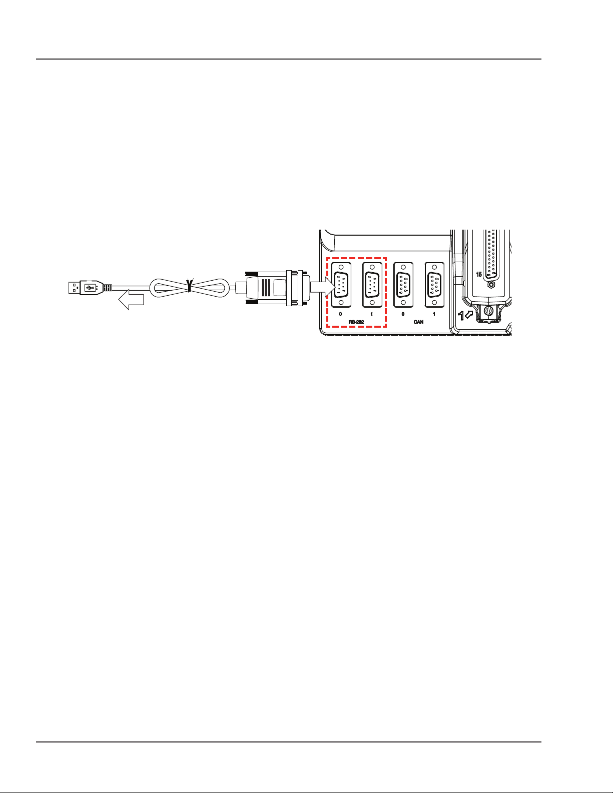
The RS232 cable enables users to connect the OP4200 to a PC to access the IP address modification
interface. It also allows users to perform various troubleshooting or reflashing activities.
OP4200
TO PC (USB)
RS232
TO OP4200
Figure 7: Connecting the RS232 to USB cable
4. Connect the USB connector to a computer or laptop. Wait for the computer to discover the new
connection.
5. Connect the RS232 connector end to the RS-232 (port 0) connector on the OP4200
6. Install the serial terminal application (MobaXterm) on your computer:
- Using an internet browser go to MobaTek’s mobaXtem website: http://mobaxterm.mobatek.net/.
- Click on the ”Download” section.
- Select the “Home Edition” version of MobaXterm and click on “Download Now”
- Select the “Portable edition” of “MobaXterm Home edition”
- Save the file in a known location in your computer.
- Extract the contents of the zip file and double click on the extracted executable of MobaXterm
i.e.: “MobaXterm_Personal_9.4.exe” the program will start (Note that there is no need to install
anything in your computer).
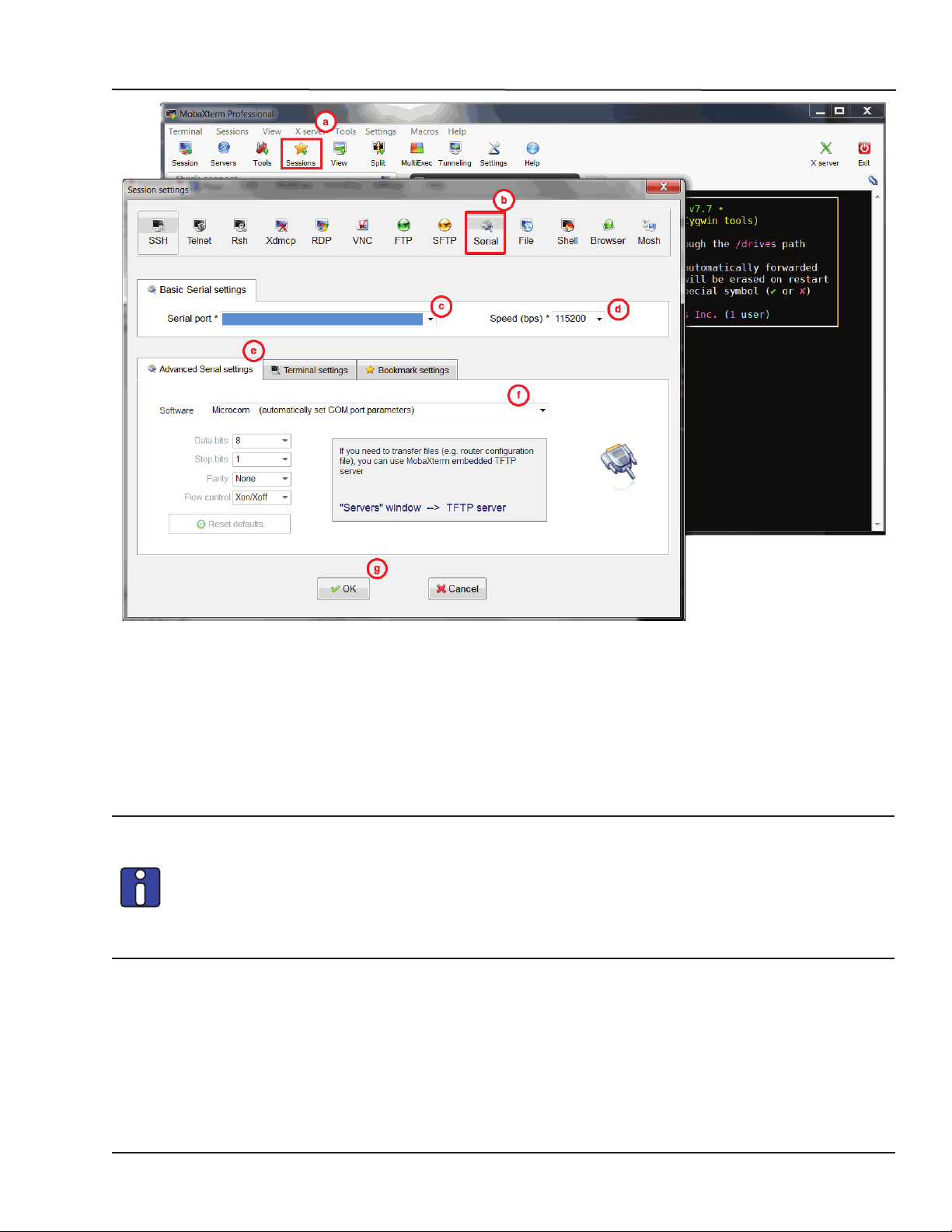
7. In MobaXterm:
a. Click the Sessions button to start a new session
b. In the Session Settings window, click on the Serial Button
16 OPAL-RT Technologies OP4200 User Manual
Page 17
OP4200 Hardware
Initial Setup
Figure 8: Starting a serial session in MobaXterm
c. Select the serial (COM) port to which the OP4200 is connected (it should appear automatically
in the list)
d. Set the Speed to 115200
e. Click on the “Advanced settings” tab
f. For the “Serial engine” field, select “Microcom” to have the rest of the parameters selected
automatically
g. Click OK to start the session.
If the OP4200 was already switched on before starting this process, clicking OK does not
open the OP4200 System Configuration screen. The user must press Enter (or use the
“config” command once logged into the system) to open the OP4200 System Configuration
screen.
If the OP4200 is switched off during this process, the boot console appears when the
OP4200 is switched on and then the configuration screen pops up.
OP4200 User Manual OPAL-RT Technologies 17
Page 18
OP4200 Hardware
Initial Setup
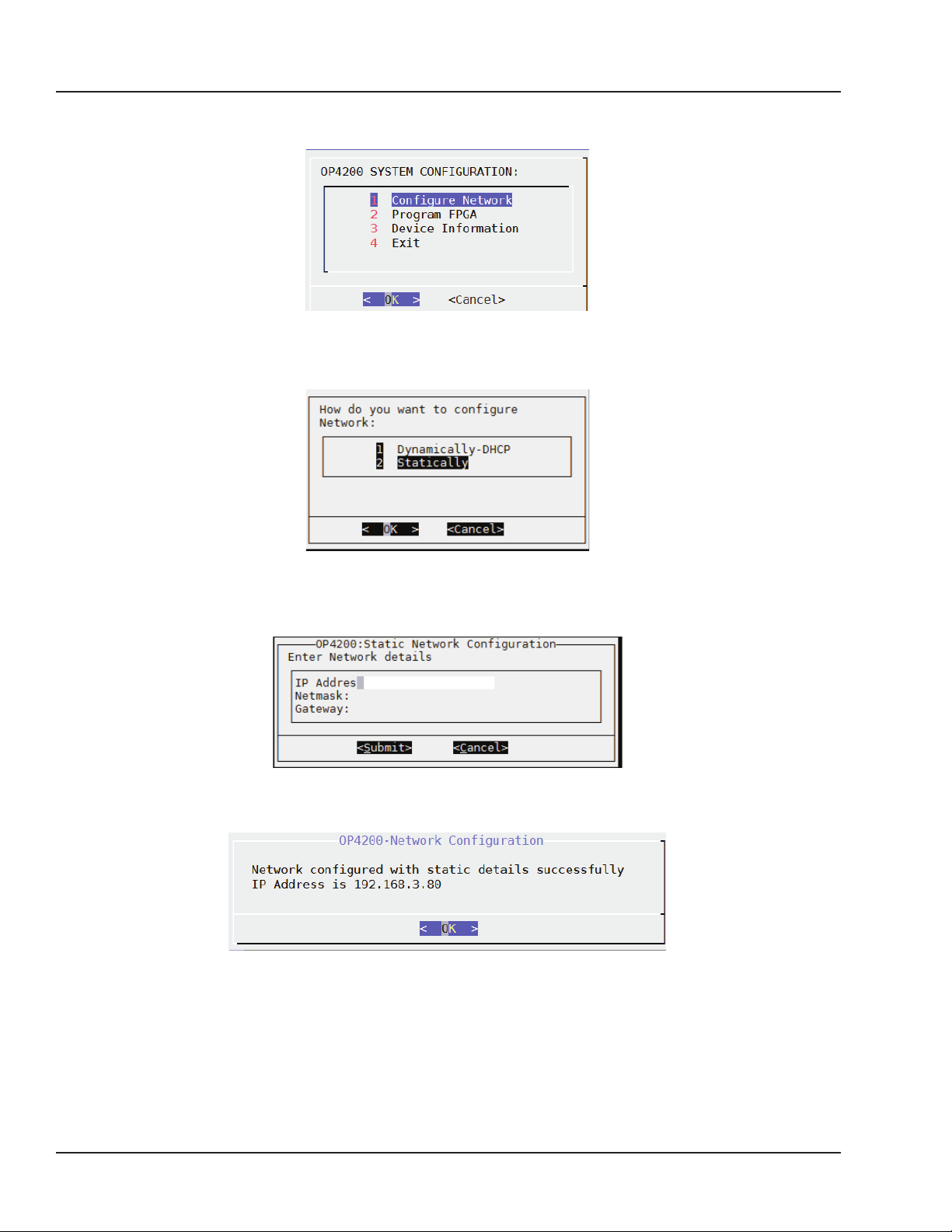
8. In the OP4200 System Configuration screen (Figure 9). Select Configure Network and click OK
(Figure 9).
Figure 9: OP4200 System Configuration screen
In the next screen (Figure 10), select “2 Statically” and click OK.
Figure 10: Network Configuration screen
- Type the following information in the next screen (Figure 11): IP address, Netmask and Gateway
(your IT department should provide you with the information).
Figure 11: IP address modification screen
- Click Submit. A confirmation screen appears (Figure 12).
Figure 12: IP address change confirmation screen
Click OK to return to the main menu. Click 4 Exit and close MobaXterm.
Your OP4200 is now ready to use and can be connected to your network. Once it is connected to the
network, you should test communication by pinging the OP4200 from your computer
18 OPAL-RT Technologies OP4200 User Manual
Page 19
Testing Signals Using the Loopback Kit
OP4200 Hardware
Initial Setup
NOTE
The following procedure is only used for test purposes when no external source is available.
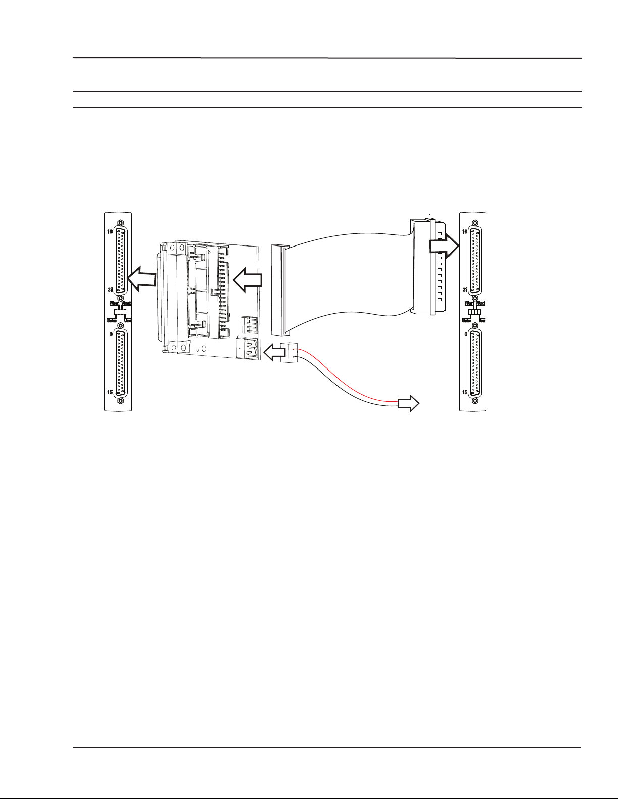
The loopback kit included in the starter kit allows users to test system signals. Connection is made easy
with a custom flat cable that matches OPAL-RT standard DB37 pin assignments.
The loopback kit allows users to test signals by connecting the output cassette to the input cassette. If
the input reads each output signal, the unit is functioning properly and is ready to be put into service.
OUTPUT
CASSETTE
LOOPBACK BOARD
To external
source
INPUT
CASSETTE
Figure 13: Connecting the loopback kit
1. Connect one end of the flat cable to the loopback board
2. Connect the loopback board to the OP4200 DB37 output cassette
3. Connect the other end (DB37 connector) of the flat cable to the OP4200 DB37 input cassette
4. When this kit is used to test digital signals, connect the Vuser (required to preserve isolation) from
the loopback board (connector end) to an external source (wire end).
OP4200 User Manual OPAL-RT Technologies 19
Page 20

OP4200 Hardware
Pin Assignments
PIN ASSIGNMENTS
Conditioning cassettes come with either one (analog) or two (digital) DB37 connectors. These
connectors respect OPAL-RT’s standard DB37 pinout, as shown in the table below.
Ch. 00-15 Ch. 16-31
DB37
Module pin
assignment
DB37
Module pin
assignment
DB37
Module pin
assignment
1 +CH00 20 -CH00 1 +CH16 20 -CH16
2 +CH01 21 -CH01 2 +CH17 21 -CH17
3 +CH02 22 -CH02 3 +CH18 22 -CH18
4 +CH03 23 -CH03 4 +CH19 23 -CH19
5 +CH04 24 -CH04 5 +CH20 24 -CH20
6 +CH05 25 -CH05 6 +CH21 25 -CH21
7 +CH06 26 -CH06 7 +CH22 26 -CH22
8 +CH07 27 -CH07 8 +CH23 27 -CH23
9 +CH08 28 -CH08 9 +CH24 28 -CH24
10 +CH09 29 -CH09 10 +CH25 29 -CH25
11 +CH10 30 -CH10 11 +CH26 30 -CH26
12 +CH11 31 -CH11 12 +CH27 31 -CH27
13 +CH12 32 -CH12 13 +CH28 32 -CH28
14 +CH13 33 -CH13 14 +CH29 33 -CH29
15 +CH14 34 -CH14 15 +CH30 34 -CH30
16 +CH15 35 -CH15 16 +CH31 35 -CH31
17 36 17 36
18 Vuser 1A* 37 Vrtn 1A* 18 Vuser 2A* 37 Vrtn 2A*
19 19
DB37
Module pin
assignment
00+
01+
02+
03+
04+
05+
06+
07+
08+
09+
10+
11+
12+
13+
14+
15+
Vuser
1
20
-00
-01
-02
-03
-04
-05
-06
-07
-08
-09
-10
-11
-12
-13
-14
-15
Vrtn
37
19
Table 2: General pin assignments
Vuser and Vrtn signals are only used with digital output modules
20 OPAL-RT Technologies OP4200 User Manual
Page 21

TROUBLESHOOTING HARDWARE SETUP
Problem Possible Cause Solution
Nothing happens when I connect my
RS232 cable
RS232 cable driver not detected Download driver from http://www.
prolific.com.tw/US/ShowProduct.
aspx?p_id=225&pcid=41
No serial terminal software detected Install MobaXterm from http://
mobaxterm.mobatek.net/download.html
OP4200 Hardware
Troubleshooting Hardware Setup
OP4200 User Manual OPAL-RT Technologies 21
Page 22

22 OPAL-RT Technologies OP4200 User Manual
Page 23
OP4200 HARDWARE - CASSETTES
OP4230-1 16 ANALOG OUTPUTS
OP4200 HARDWARE - CASSETTES
OP4230-1 16 ANALOG OUTPUTS
FEATURES
• • 16 single-ended analog output channels
• • All outputs are sampled simultaneously, up to 1 MS/s
• • 16 bit resolution
• • ±16 V voltage range output
• • ±15 mA maximum current per channel
• • Factory calibrated
DESCRIPTION
The OP4230-1 digital to analog converter (DAC) provides 16 single-ended digital output channels.
Each channel uses a 16-bit resolution digital-to-analog converter.
Each OP4230-1 can sample up to 1 MS/s, giving a total throughput of 8 MS/s, all channels are
simultaneously sampled. The onboard EEPROM provides offset and gain data adjustment written
during the calibration process, as well as over-voltage protection.
By default, the maximum output signal is set to ±16 volts.
SCHEMATICS
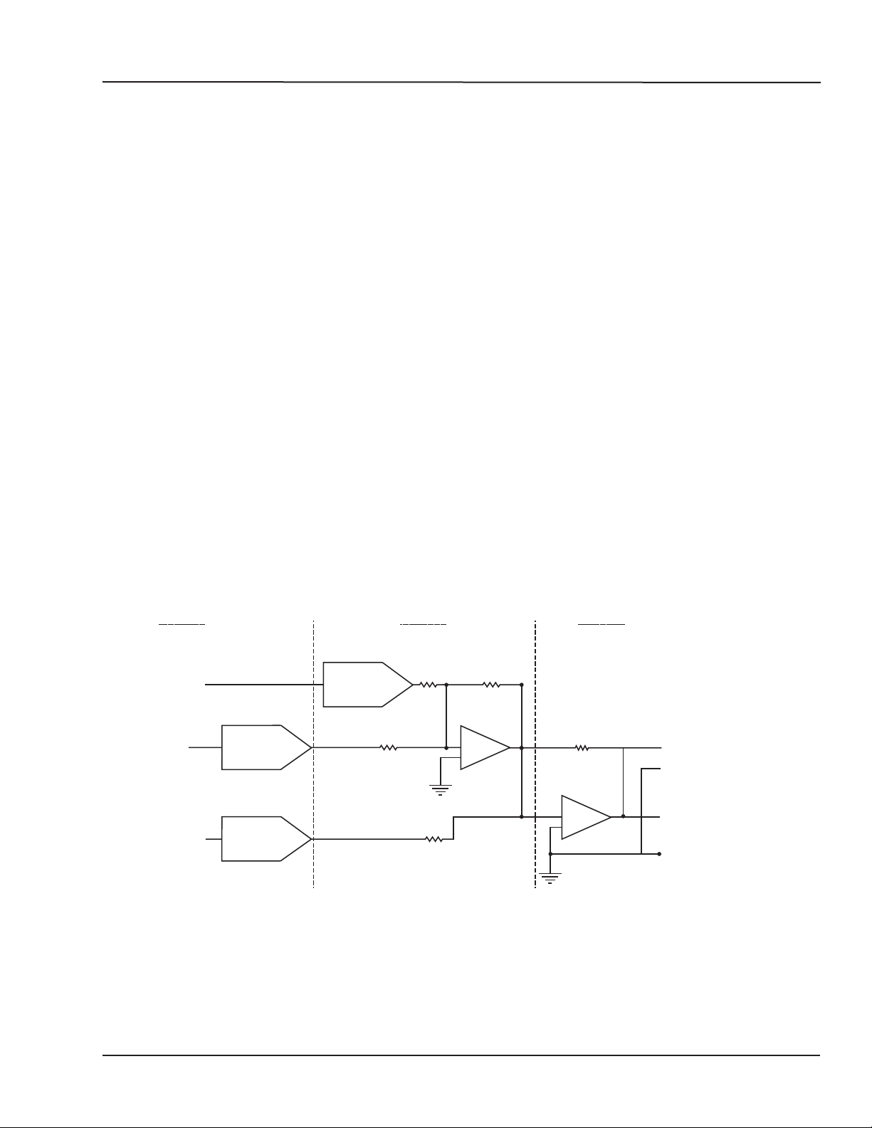
Figure 1 represents a simplified schematic of one channel of the OP4230-1 module. It is composed of
three stages: the first stage consists of one gain DAC and one offset DAC; the second stage consists
of a signal DAC with an operational amplifier that allows for gain adjustments; the third stage consists
of an operational amplifier that receives final signal value and integrates the offset.
STAGE 1
SIGNAL DATA
GAIN DATA
OFFSET DATA
VREF SIGNAL DAC
GAIN DAC
OFFSET DAC
STAGE 2
STAGE 3
-
+
-
+
RJ45
OUTPUT +
RJ45 GND
DB37
OUTPUT +
DB37 GND
Figure 14: Output DAC circuit
OP4200 User Manual OPAL-RT Technologies 23
Page 24
OP4200 HARDWARE - CASSETTES
TYPICAL APPLICATIONS
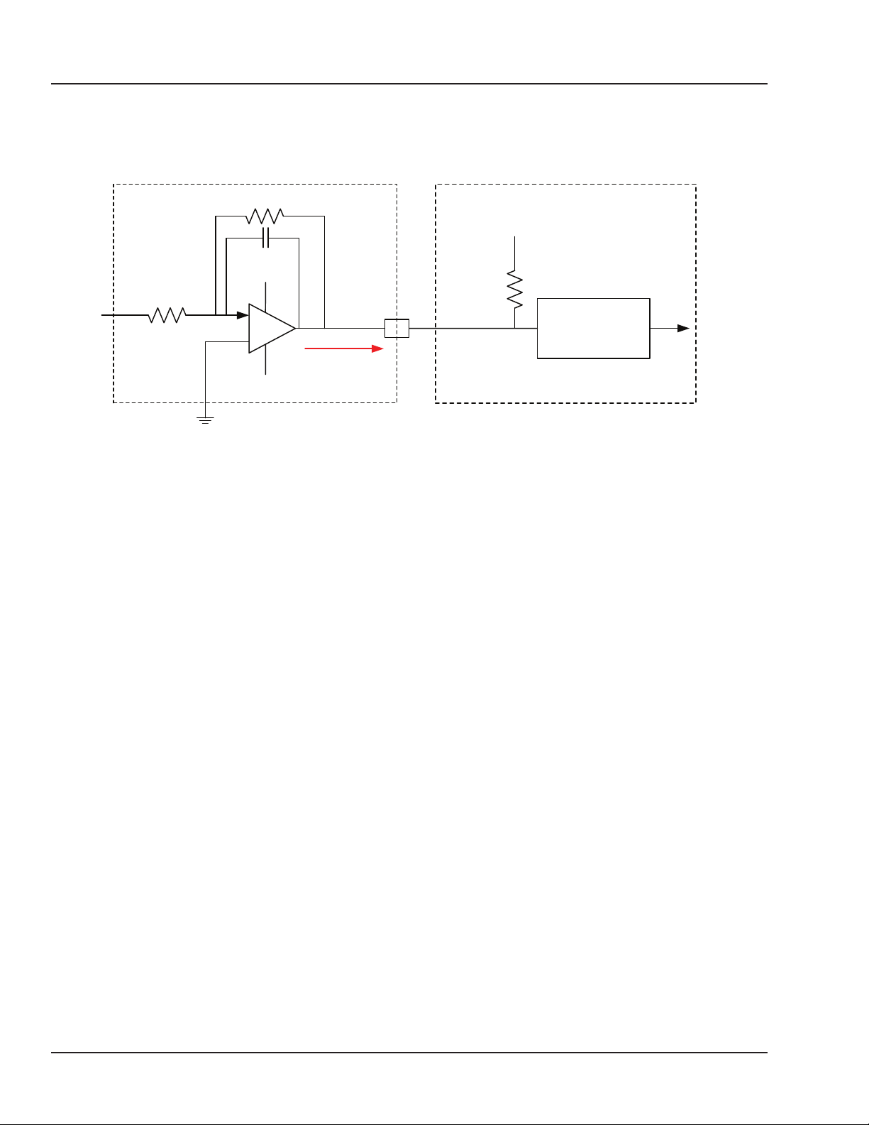
The following diagrams provide an example of a typical application using the OP4230-1.
OP4230-1 Analog Output
-
+
GND
Figure 15: Figure 2: Typical application diagram
15 mA max
Client Side
VDC+
Analog In
Signal
Conditionning
24 OPAL-RT Technologies OP4200 User Manual
Page 25
OP4200 HARDWARE - CASSETTES
OP4240-1 16 ANALOG INPUTS
OP4240-1 16 ANALOG INPUTS
FEATURES
• 16 differential analog input channels
• All inputs are sampled simultaneously for additional simulation accuracy. They can be sampled up
to 400 KS/s
• 16 bit resolution
• ±20V input range
DESCRIPTION
The OP4240-1-1 module provides 16 differential analog input channels. Each channel uses a 16-bit
resolution analog-to-digital converter. By default, the maximum input signal is set to ±20 volts.
SCHEMATICS
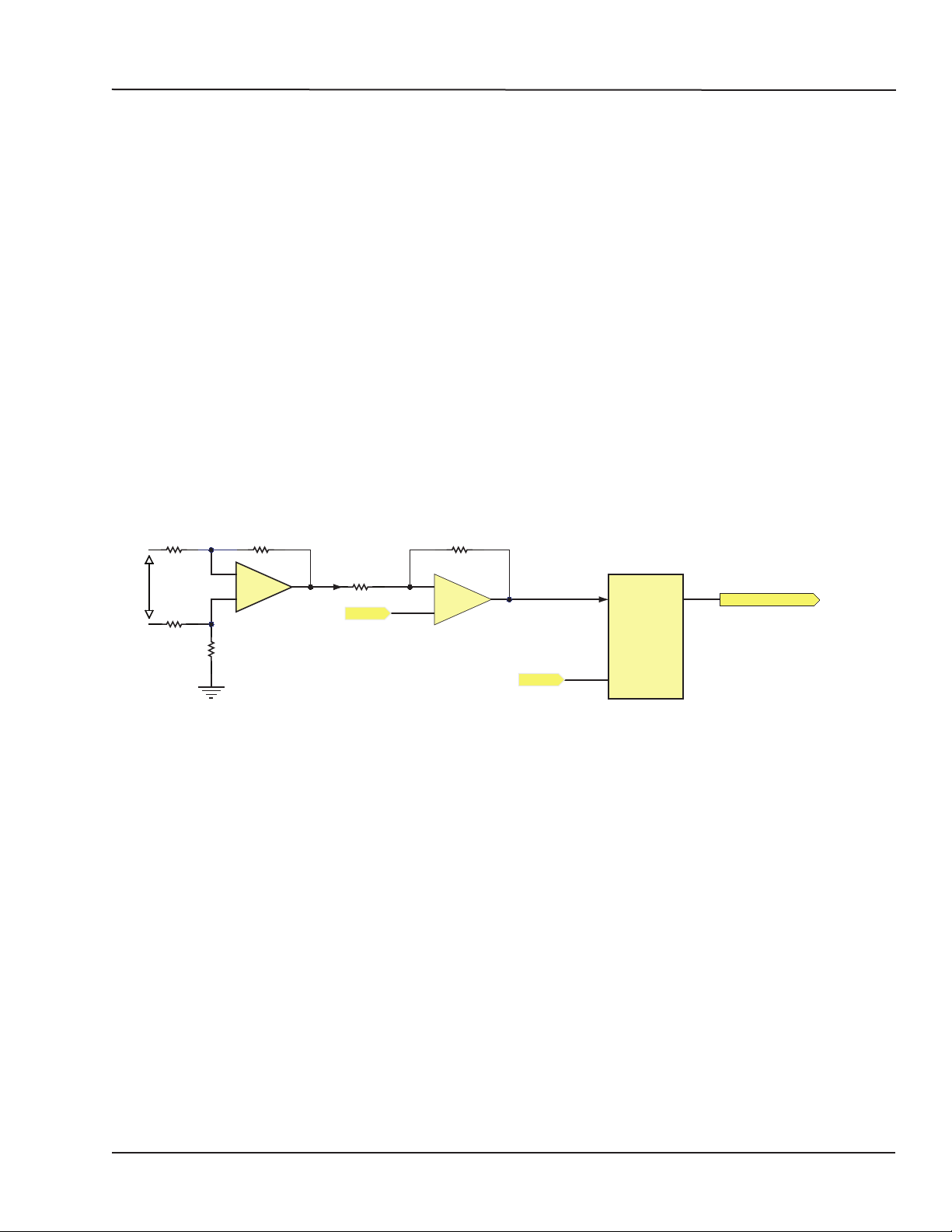
Figure 3 represents a simplified schematic of one channel of the OP4240-1 modules. It is composed of
three stages: the first stage consists of one operational amplifier that works in differential input mode
and permits gain adjustment; the second stage, the level shifter, forms the signal for the A/D converter
input; the third stage occurs after the conversion to the digital type, as the signal is sent to the carrier
board.
V in
A / D ConverterLevel ShifterDifferential Amplifier
-
+
VREF
-
+
VREF
VIN
REF
OUT
Serial Data Out
Figure 16: Figure 3: Differential input ADC circuit
OP4200 User Manual OPAL-RT Technologies 25
Page 26
OP4242-1 16 Analog inputs
OP4242-1 16 ANALOG INPUTS
FEATURES
• 16 analog input channels, 16 bits, 2 MSPS
• All inputs are sampled simultaneously for additional simulation accuracy. They can be sampled up
to 2 MS/s
• 16 bit resolution
• ±20V input range.
DESCRIPTION
The OP4240-1-1 module provides 16 differential analog input channels. Each channel uses a 16-bit
resolution analog-to-digital converter. By default, the maximum input signal is set to ±20 volts.
SCHEMATICS
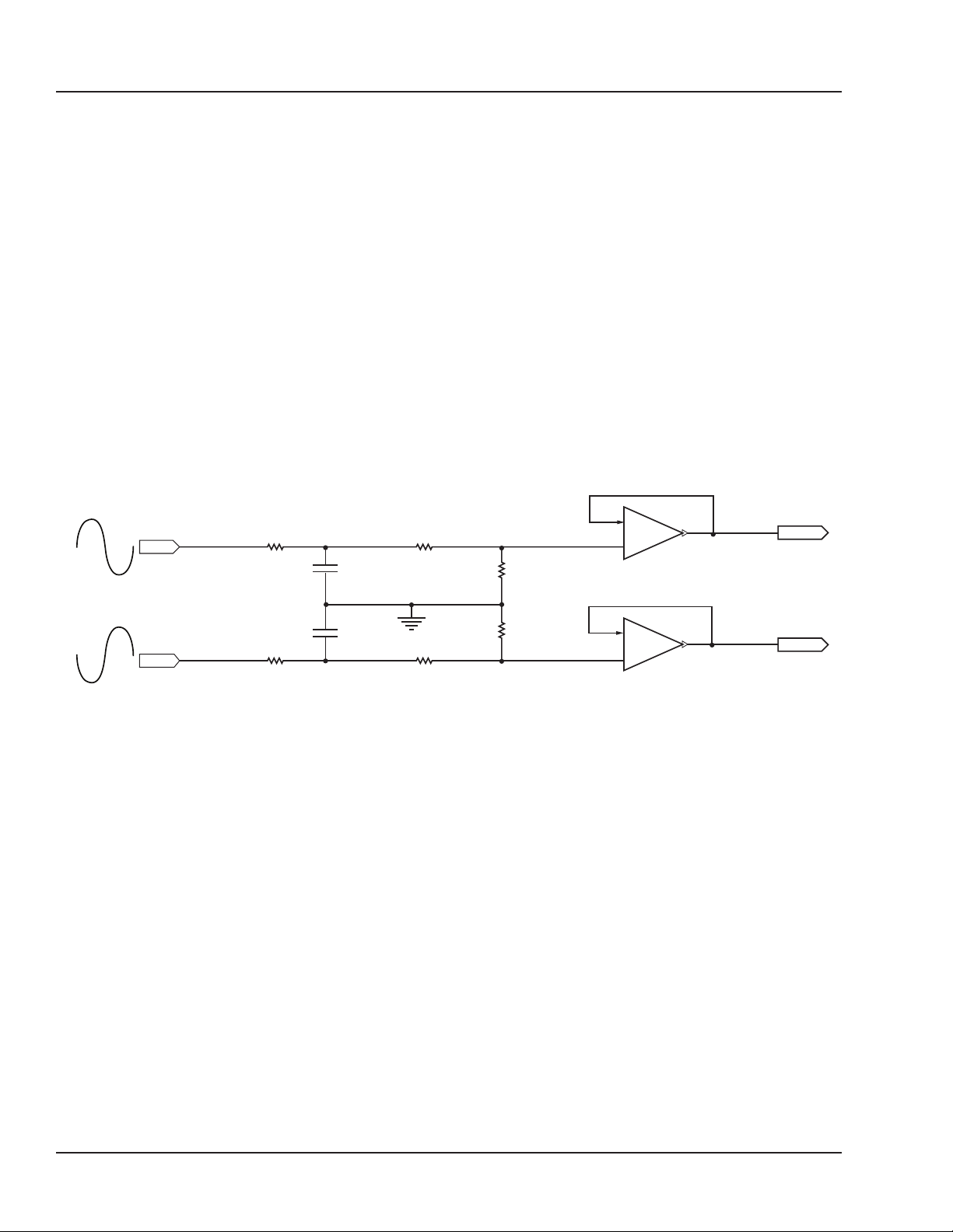
The figure below represents a simplified schematic of the input stage of the OP5342 modules. The first
filter removes excessive noise. The signal is then attenuated to maintain the maximum input voltage
range of ±20 Volts with no additional resistors.
10
475k 1%
R1
R5
1K0 1%
1K0 1%
R1
200pF
R1
200pF
0
0
-10
+ IN
-10
Filter 800kHz
10
+ IN
R2
R6
R1
24K91%
R1
24K91%
475k1%
-
- To ADC
+
-
- To ADC
+
Figure 17: Differential input ADC circuit
26 OPAL-RT Technologies OP4200 User Manual
Page 27
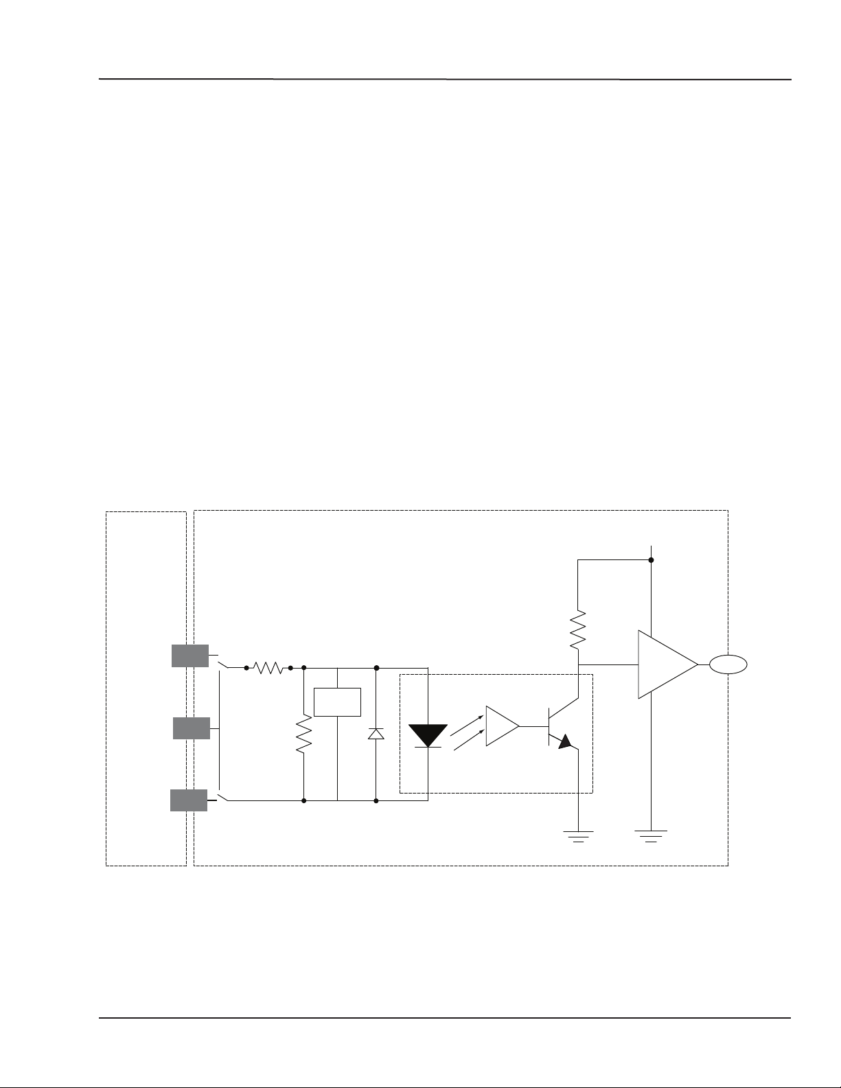
OP4250-1 32 DIGITAL INPUTS
OP4250-1 32 DIGITAL INPUTS
The OP4250-1 features 32 optically isolated input channels. All are sampled simultaneously for
additional simulation accuracy. It is perfectly suited to interface real life environment signals to TTL or
differential levels for RT-LAB simulator, providing perfect electrical isolation and discharge protection.
FEATURES
• 32 optically isolated input channels.
• All inputs are sampled simultaneously, at up to 10 MSPS.
• Inputs are read in parallel for any size bus simulation.
• Hardware configurable filters, and conditioning inputs for customization.
• Choice of sink or source inputs connection (anode and cathode side available).
• Minimum current input of 3.6 mA.
• 5V to 30V input voltage range.
• 30V maximum reverse protection.
INTERFACES
Inputs
The optically isolated inputs accept a wide input voltage range, from 5 to 30 Volts, according to user
requirements. They have a low threshold current; typically 3.6 mA.
Each input has a reverse voltage protection of up to 30 Volts provided by a Schottky diode.
User
Digital Input Isolated
+5VDC
Vuser
(5 to 30V)
Din
Vuser_RTN
1
2
1
2
OPTION 1: COMMON ANODE
OPTION 2: COMMON CATHODE
R
OPTIONAL
FILTER
MODE SELECTION WITH ON-BOARD ZERO-OHM RESISTORS
to_FPGA
Figure 18: OP4250-1 isolated digital input drawing
OP4200 User Manual OPAL-RT Technologies 27
Page 28
OP4250-1 32 DIGITAL INPUTS
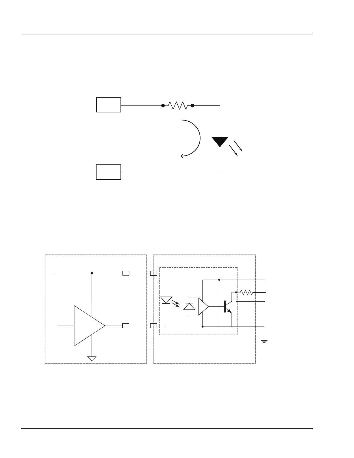
When current flows from Din + to Din -, the output of opto-coupler A is low and the Din_FPGA signal is
low.
When no current flows, the opto-coupler output A is high and the Din_FPGA signal is high.
The signal conditioning module inputs have both anode and cathode sides available to the user (on the
I/O connector).
R
VUser
Max. 10 mA
Din
MODE 1: COMMON ANODE
Figure 19: Both Din + and Din - are available to the user
TYPICAL APPLICATIONS
The diagrams below illustrate typical application examples.
INTERFACE BETWEEN CMOS DRIVE AND OPAL-RT Din
User
Vcc
TC4049/4050
I
OPAL-RT Din
+5V
+2.5V/+3.3V
FPGA
Figure 20: Typical digital input circuit
28 OPAL-RT Technologies OP4200 User Manual
Page 29
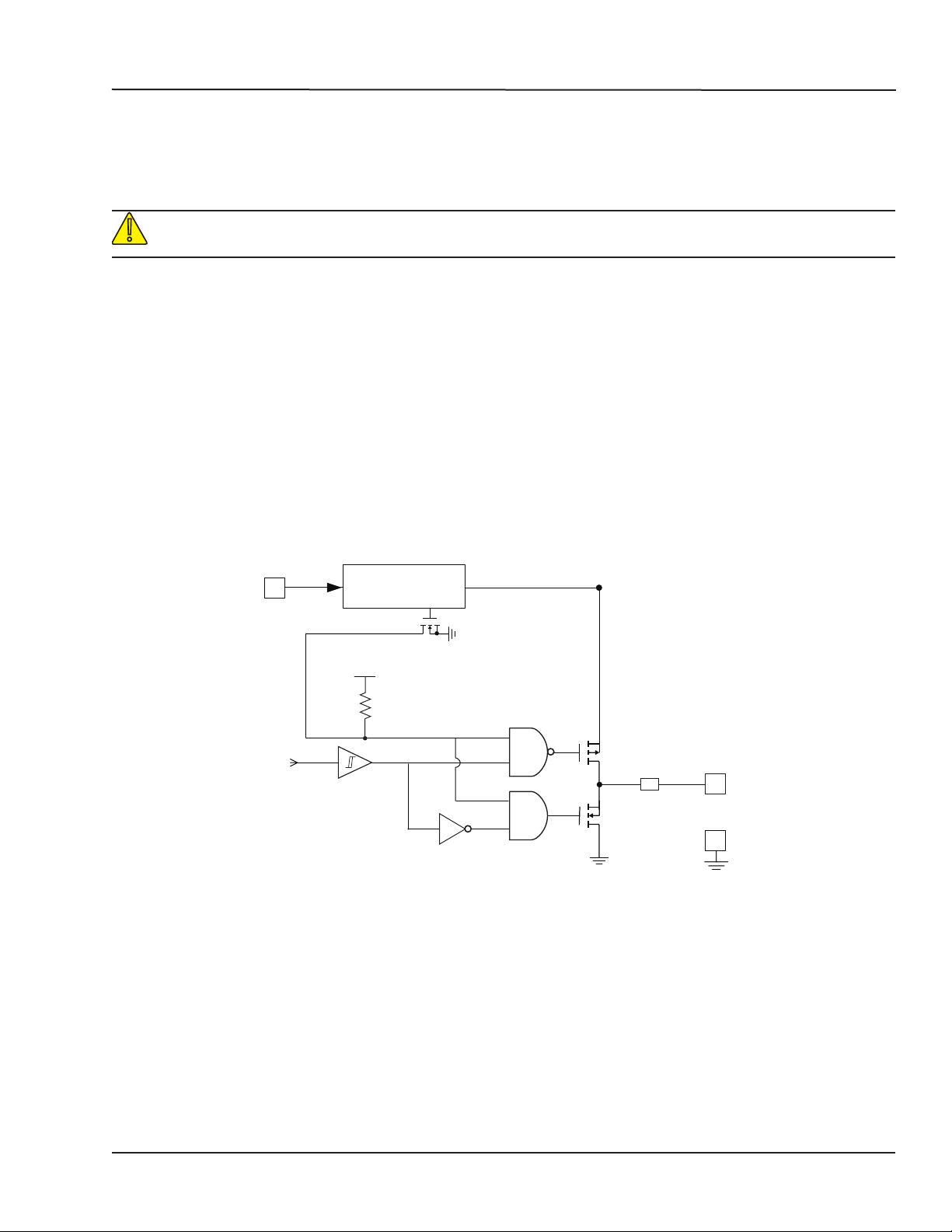
OP4260-1 32 DIGITAL OUTPUTS
!
OP4260-1 32 DIGITAL OUTPUTS
The OP4260-1 provides 32 push-pull digital outputs divided in two banks of 16. Each bank can be
separately powered by the user. The board can accept up to 30Vdc and can sink or source 50 mA dc
(recommended) with no trip action.
Higher currents will trip the current protection and all the output levels provided in this
datasheet will not be applicable
FEATURES
• 32 Dout push-pull
• Wide operating voltage range: Vuser 5 Vdc to max 30 Vdc
• Load current up to 50 mA DC per output
• O/V and reverse voltage supply protection
• Short-circuit current limitation
• Operating frequency DC-500Khz
• Low ON/OFF time propagation delay: ≤ 200ns @ 25°C at 5 V
• Low ON/OFF time propagation delay: ≤ 65ns @ 25°C from 15 to 30 V (optional)
• Outputs are tri-stated.
• Outputs may be connected in parallel for higher (2 times) current capability: use matched pair
(example: DOUT_0 with 1 , DOUT_2 with 3, etc.)
ENA
IN
Supply protections
Over Voltage
Reverse Voltage
V
CC
FAULT
GND-ISO
SC Protection
GND-ISO
DOUT
GND-ISO
User supply
From Simulator
Figure 21: OP4260-1 block diagram
Recommendations
Users should adjust the power supply level (through the DB37 connector) to get the proper high
voltage level at the DOUT.
Use a proper damping circuit, (a serial resistor capacitor circuit tied to the GND as close as possible
to the user Device Under Test) to minimize ringing and over/undershoot according to the connection
length (from OP4260-1 to user device).
The following parameters are a good starting point for the RC values: R=150Ω , C = 100pF. Tuning is
necessary, according to application parameters.
OP4200 User Manual OPAL-RT Technologies 29
Page 30

OP4200 Hardware Specifications
OP4200 General Specifications
OP4200 HARDWARE SPECIFICATIONS
OP4200 GENERAL SPECIFICATIONS
Product name OP4200
CPU ARM® Processor dual-core Cortex A9 1GHz (1000MHz optional)
Memory 16 GB SD card, 1024 MB SRAM
O/S Linux-based real-time operating system
FPGA Xilinx Zynq®XC7Z030, Kintex™-7 FPGA, 125K LUT
I/O lines 128 lines, routed to cassette conditioning modules
Communication ports 2 GTX SFP connectors, up to 5Gbps
I/O connectors DB37F
I/O cassette slots 4 slots for I/O cassettes
Power supply External Power supply, 100-240VAC, 50-60Hz, 60VA
Dimensions 25 x 22x 28 cm (9.8’’ x 8.7’’ x 11.2’’) HxWxD
Weight 4.54kg (10 lbs)
Operating temperature 10 to 35 ºC (50 to 95ºF)
Storage temperature -55 to 85ºC (-67 to 185ºF)
Maximum rated ambient
temperature
Relative humidity 10 to 90% non-condensing
Maximum altitude 2000 m (6562 ft.)
RS232
CAN
24V ± 10% @ max 2.5A
40Cº (104ºF)
30 OPAL-RT Technologies OP4200 User Manual
Page 31

OP4200 Hardware Specifications
OP4200 General Specifications
OP4230-1 SPECIFICATIONS
Product Name OP4230-1
Part Number 126-0157
Number of channels 16 single-ended
Resolution 16 bits
Default range ± 16 Volts
Maximum current 15 mA
Max. Sampling Frequency 1 MS/s
Min Conversion / Acquisition Time 1 μs per channel
DAC Type 8 x Dual DAC with 10 MBit/s Serial Output Transfer
Dc Transfer Characteristics
CMRR 100 dB
Dynamic Characteristics
Calibration Programmable gain and offset calibration for each D/A. Calibration factors are
Maximum noise 20 mV peak-to-peak
Maximum offset ± 80 mV
Recommended warm-up time 5 min.
Calibration interval as required
Dimensions 6.60 cm x 12.50 cm (2.6” x 4.92”)
I/O connector 80-pin high speed header to carrier
Environmental
Operating temperature 10 to 40 °C
Storage temperature -55 to 85 °C
Relative humidity 10 to 90%, non condensing
Maximum altitude 2,000 m
stored in on-board non-volatile memory (EEPROM)
OP4200 User Manual OPAL-RT Technologies 31
Page 32

OP4200 Hardware Specifications
OP4200 General Specifications
OP4240-1 SPECIFICATIONS
Product Name: OP4240-1
Number of channels: OP4240-1: 16 differential
Resolution: 16 bits
Max. Sampling Frequency: 500 kS/s
Min Conversion / Acquisition Time: 2.5 μs per channel
ADC Type: 8 x Dual ADC with 10 MBit/s Serial Output Transfer
Nominal Input Ranges (V)
Positive Full Scale Negative Full Scale
+120.0 -120.0
+100.0 -100.0
+80.0 -80.0
+60.0 -60.0
+40.0 -40.0
+20.0 (hardware default value) -20.0
Calibration Calibration factors are stored in on-board non-volatile memory (flash memory).
Recommended warm-up time: 5 min.
Calibration interval: as required
Dimensions: 6.60 cm x 12.50 cm (2.6” x 4.92”)
I/O connector: 80-pin high speed header to carrier
Environmental
Operating temperature: 10 to 40 °C
Storage temperature: -55 to 85 °C
Relative humidity: 10 to 90%, non condensing
Maximum altitude: 2,000 m
This memory is not accessible for calibration.
32 OPAL-RT Technologies OP4200 User Manual
Page 33

OP4200 Hardware Specifications
OP4200 General Specifications
OP4242-1 SPECIFICATIONS
Product name OP4242 analog to digital converter (16 analog inputs - 2 MSPS)
Part number 410-0072
Number of channels 16
Resolution 16 bits
Input impedance
Max. Sampling Frequency 2 MSPS
Min Conversion / Acquisition Time 510 nanoseconds per channel on OP4200
ADC Type 8 x Dual ADC
Input voltage range ± 20V
Bandwidth Small signal (-3 dB): 400 kHz
Accuracy ±10mV on the entire ±20V range
System noise max. 5Vrms
Recommended warm-up time 5 min.
Dimensions 6.60 cm x 12.50 cm (2.6” x 4.92”)
Operating temperature 0 to 50 ºC (32 to 122ºF)
Storage temperature -55 to 85ºC (-67 to 185ºF)
Relative humidity 10 to 90%, non condensing
Maximum altitude 2,000 m (6562 ft.)
1 M
Ω
OP4200 User Manual OPAL-RT Technologies 33
Page 34

OP4200 Hardware Specifications
OP4200 General Specifications
OP4250-1 SPECIFICATIONS
Product name OP4250-1 (32 opto-isolated digital inputs)
Number of channels 32 digital inputs
Isolation Optical isolator
Connection mode Anode and cathode available on connector
Input current 3.6 mA, current limiting diode
Reverse voltage protection Schottky diode
Maximum reverse voltage protection 30 Volts
Detection threshold Separate Schmitt Trigger
Voltage range 4 to 50 Vdc
Delay Low-to-High 110 ns
Delay High-to-Low 60 ns
Rise/Fall times 6 ns/6 ns
Form factor Mezzanine Type B
Dimensions 6.60 cm x 12.50 cm (2.6” x 4.92”)
I/O connector 80-pin high speed header to carrier (internal connection
Operating temperature 10 to 40 ºC (50 to 104ºF)
Storage temperature -55 to 85ºC (-67 to 185ºF)
Relative humidity 10 to 90%, non condensing
Maximum altitude 2,000 m (6562 ft.)
DB37F (external connection)
34 OPAL-RT Technologies OP4200 User Manual
Page 35

OP4260-1 SPECIFICATIONS
Product name OP4260-1 (32 digital outputs - push-pull)
Number of channels 32 digital outputs
2 banks of 16, fully isolated and independant of each other
Isolation Galvanic isolator
Output Protection 50 mA resettable fuse
Protection thresholds Over voltage: 30V ±5%
Under voltage protection 5V ±2.5%
Reverse voltage: maximum 30 V.
Output Voltage range 5 to 30 Vdc max
Output configuration Push-pull, tri-state output
Delay Low-to-High ≤ 65ns @ 25°C for 30 V
≤ 200ns @ 25°C for 5 V
Delay High-to-Low ≤ 65ns @ 25°C for 30 V
≤ 200ns @ 25°C for 5 V
Rise/Fall times <= 15 ns
Form factor Mezzanine Type B
Dimensions 6.60 cm x 12.50 cm (2.6” x 4.92”)
I/O connector 80-pin high speed header to carrier
Operating temperature 10 to 40 ºC (50 to 104ºF)
Storage temperature -55 to 85ºC (-67 to 185ºF)
Relative humidity 10 to 90%, non condensing
Maximum altitude 2,000 m (6562 ft.)
OP4200 Hardware Specifications
OP4200 General Specifications
OP4200 User Manual OPAL-RT Technologies 35
Page 36

Limited Warranty
LIMITED WARRANTY
LIMITED WARRANTY
OPAL-RT Technologies Inc. warrants to the original purchaser and/or ultimate customer (“Purchaser”)
of OPAL-RT products (“Product”) that if any part thereof proves to be defective in material or
workmanship within one (1) year, such defective part will be repaired or replaced, free of charge,
at OPAL-RT Technologies’ discretion, if shipped prepaid to OPAL-RT Technologies Inc. at 1751
Richardson, suite 2525, Montreal, Quebec, Canada, H3K 3G6, in a package equal to or in the original
container. The Product will be returned freight prepaid and repaired or replaced if it is determined by
OPAL-RT Technologies Inc. that the part failed due to defective materials or workmanship. Otherwise,
the fees will be charged to the client (see article “WARRANTY LIMITATION AND EXCLUSION”). The
repair or replacement of any such defective part shall be OPAL-RT Technologies’ sole and exclusive
responsibility and liability under this limited warranty.
Purchaser must request an RMA number before shipping any Product for repair:
1. Access the OPAL-RT website (www.opal-rt.com/support/ return-merchandise-authorization-rmarequest), click on support and select Return Merchandise (RMA).
2. Fill out the online form and submit.
3. OPAL-RT’s Support department will evalute the return and either issue an RMA number via email
- If the Product is returned for repair more than 12 months after purchase, the Purchaser is
responsible for the cost of repair. OPAL-RT will assess the repair and prepare a quote. The RMA
number will be sent with the quote.
4. Only when the Purchaser receives the RMA number, may they ship the Product, prepaid, to
OPAL-RT.
RETURN POLICY
The following fees will apply when customers return products for credit:
A full credit, less a 15% fee and less return fee will only be issued if the product is in perfect working
condition and if the product is returned within 1 month following the shipping date. If repairs are
required on the returned product, the cost of these repairs will be deducted from the credit to be
issued.
No credits will be issued beyond the one month period.
EXCLUSIONS
If third party products are part of the Product, OPAL-RT will honor the original manufacturer’s warranty.
This limited warranty does not cover consumable items, such as batteries, or items subject to wear or
periodic replacement, including lamps, fuses or filter elements.
36 OPAL-RT Technologies OP4200 User Manual
Page 37

Limited Warranty
WARRANTY LIMITATION AND EXCLUSION
OPAL-RT Technologies will have no further obligation under this limited warranty. All warranty
obligations of OPAL-RT Technologies are void if the Product has been subject to abuse, misuse,
negligence, or accident or if the Purchaser fails to perform any of the duties set forth in this limited
warranty or if the Product has not been operated in accordance with instructions, or if the Product
serial number has been removed or altered.
DISCLAIMER OF UNSTATED WARRANTIES
The warranty printed above is the only warranty applicable to this purchase. All other warranties,
express or implied, including, but not limited to, the implied warranties of merchantability or fitness for a
particular purpose are hereby disclaimed.
LIMITATION OF LIABILITY
It is understood and agreed that OPAL-RT Technologies’ liability, whether in contract, in tort, under
any warranty, in negligence or otherwise shall not exceed the amount of the purchase price paid by
the purchaser for the product and under no circumstances shall OPAL-RT Technologies be liable for
special, indirect, or consequential damages. The price stated for the product is a consideration limiting
OPAL-RT Technologies’ liability. No action, regardless of form, arising out of the transactions under this
warranty may be brought by the purchaser more than one year after the cause of actions has occurred.
OP4200 User Manual OPAL-RT Technologies 37
Page 38

CONTACT
OPAL-RT Corporate Headquarters
1751 Richardson, Suite 2525
Montréal, Québec, Canada
H3K 1G6
Tel.: 514-935-2323
Toll free: 1-877-935-2323
Technical Services
www.opal-rt.com/support
:
Note
While every effort has been made to ensure
accuracy in this publication, no responsibility
can be accepted for errors or omissions. Data
may change, as well as legislation, and you are
strongly advised to obtain copies of the most
recently issued regulations, standards, and
guidelines.
This publication is not intended to form the
basis of a contract.
UM18-34232-RVN 1.4
10/2018
OPAL-RT Technologies Inc.
 Loading...