

®
®
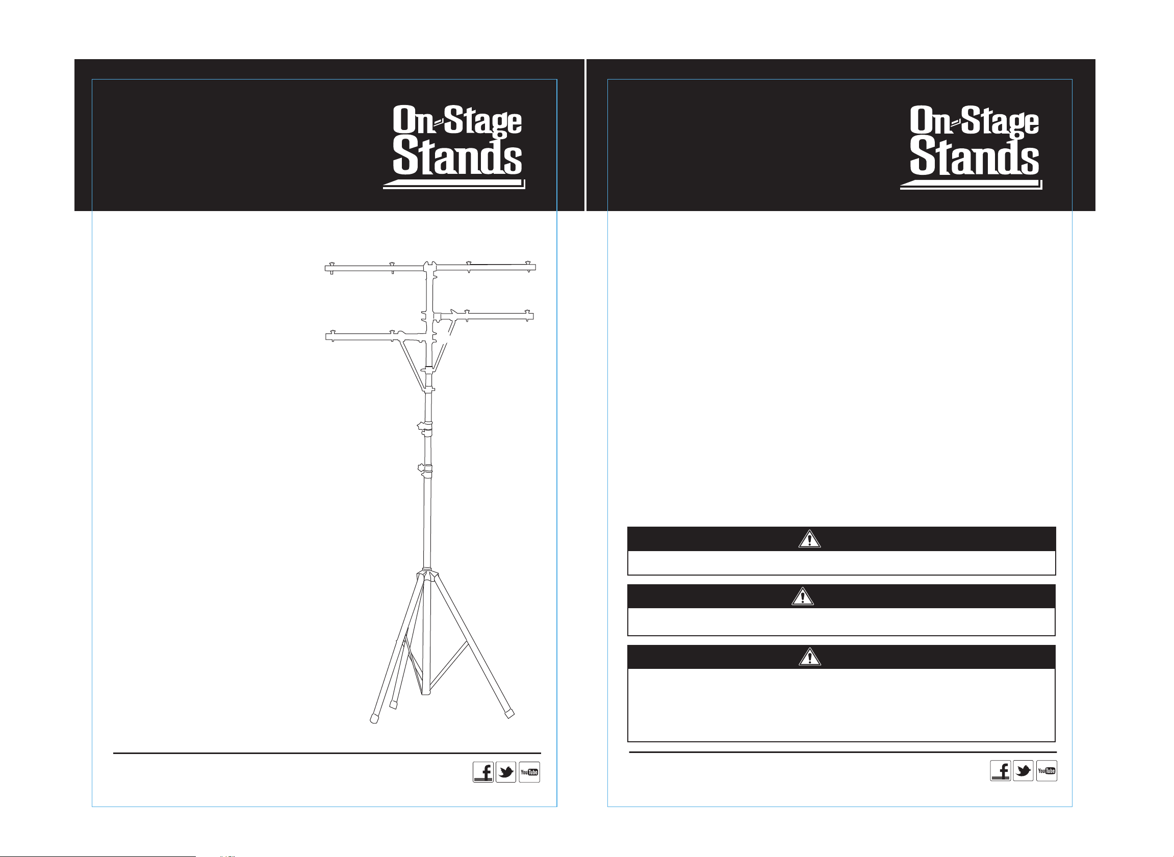
Lighting Stand Specifications
for the LS7720BLT
Vertical Shaft Specifications
Top shaft diameter: 38mm
Middle shaft diameter: 41mm
Lower shaft diameter: 45mm
Vertical Shaft Height adjustment
Maximum height : 124"
Upper shaft: 2 preset adjustment holes 8"
on center. 33" Usable shaft length
Middle shaft: 5 preset adjustment holes 8"
on center. 38" Usable shaft length
Lower shaft: 51" fixed height from floor
Safety factor
Base leg spread is 36" to 48"
7.
8.
6.
5.
4.
1.
9.
10.
Assembly Instructions for the LS7720BLT
1. Set vertical shafts at their lowest position for your convenience.
2. Set the legs to the desired base spread to support the weight of your pars.
3. Move stand to the desired location.
4. Slide the support sleeve for one of the 24-inch side bars on to the top
vertical shaft. Do not tighten knob completely.
5. Slide the support sleeve for the second 24-inch side bars on to the top
vertical shaft. Do not tighten knob completely.
6. Slide one of the 24-inch bars on to the top of the shaft.
7. Slide the second bar onto the top of the shaft.
8. Place the top 48-inch bar on the end of the upper shaft.
9. Install a par can on the right side of the top 48-inch bar. It is important
this step is done before setting the 2 lower support arms in place.
Once there is enough clearance tighten the lower side bars in place.
10. Install the remaining par cans.
11. Raise stands to desired height and tighten knobs.
12. Insert the included safety pins through the pre-drilled holes on the
vertical shaft.
CAUTION
Total Weight Capacity: 110lbs.
© 2013 TMP, Inc.
www.on-stage.com
2.
ALWAYS ALLOW AT LEAST 2” OF THE VERTICAL SHAFT INSIDE THE CLUTCH
IMPORTANT
DO NOT USE THIS PRODUCT WITHOUT THE SAFETY PIN IN PLACE.
CAUTION
FAILURE TO OBSERVE PROPER ASSEMBLY INSTRUCTIONS, EXCEEDING THE
WEIGHT CAPACITY OR FAILURE TO OBSERVE THE WARNINGS AS MENTIONED IN
THIS INSERT MAY CAUSE STAND TO COLLAPSE, BODILY INJURY OR EQUIPMENT
DAMAGE AND WILL VOID THE PRODUCT WARRANTY.
© 2013 TMP, Inc.
www.on-stage.com
 Loading...