

Page 1
Confidential
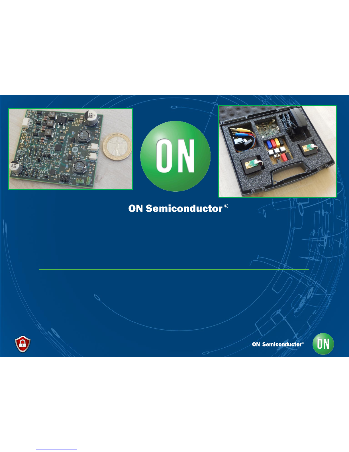
LED FRONTLIGHTING SOLUTIONS APG/AAB
NCV78763 LDM A – REFERENCE DESIGN KIT
QUICK START GUIDE & SYSTEM OVERVIEW
Document version 1.6– 29th of Aug 2016
Christiam Gasparini
System Application Engineer
Automotive APG/AAB BU - Belgium
Page 2
Confidential 2 29/08/2016
NCV78763 LDM A
v1.1
Quick Start Guide
KIT OVERVIEW
Page 3
Confidential 3 29/08/2016
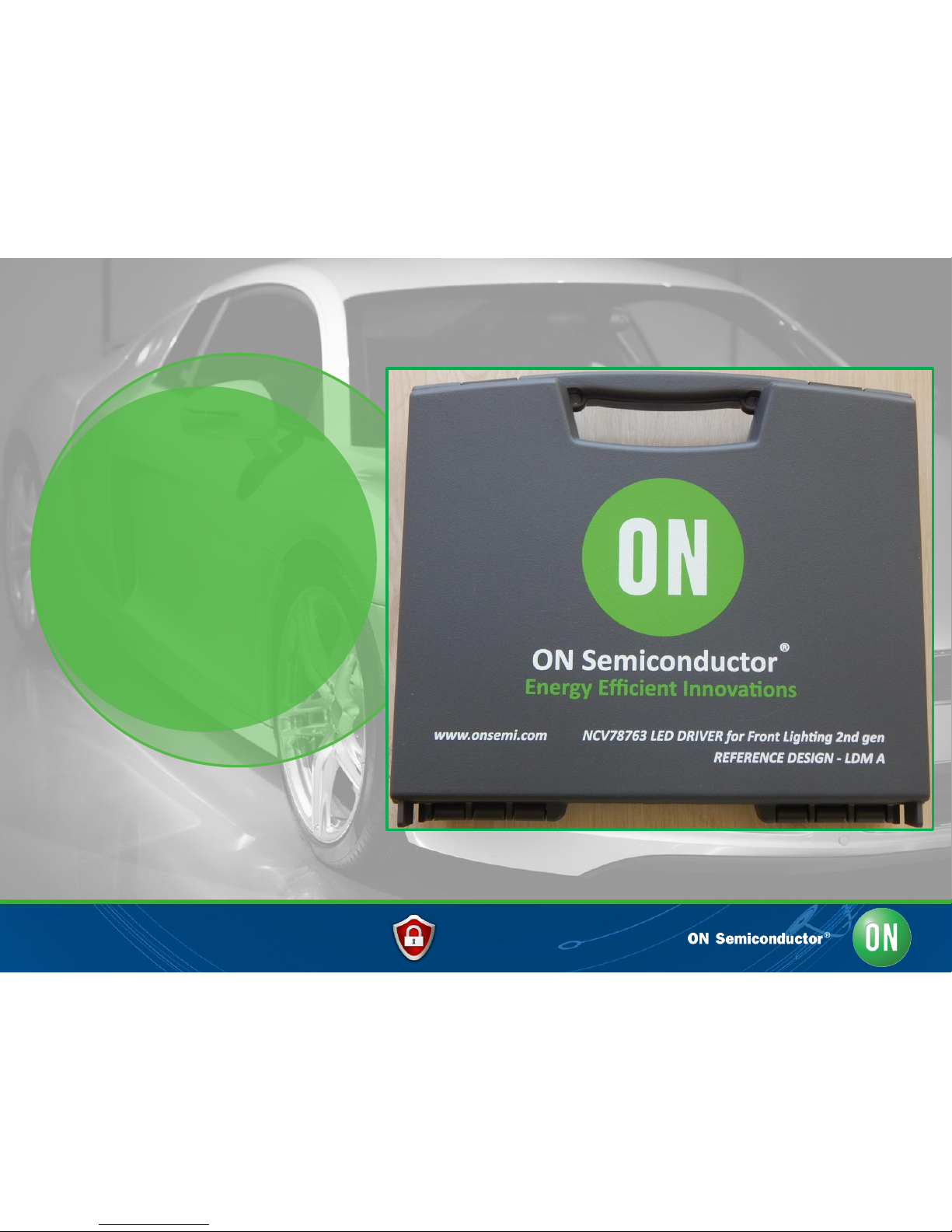
• The NCV78763 REF Design LDM A KIT v1.1 is meant for Automotive LED
Front Lighting Advanced Applications for Day Time Running Light (DRL),
Position Light (PL) and Turn Indicator (TURN), aimed for car bulb
equivalent system replacement and migration to Power LEDS. Content:
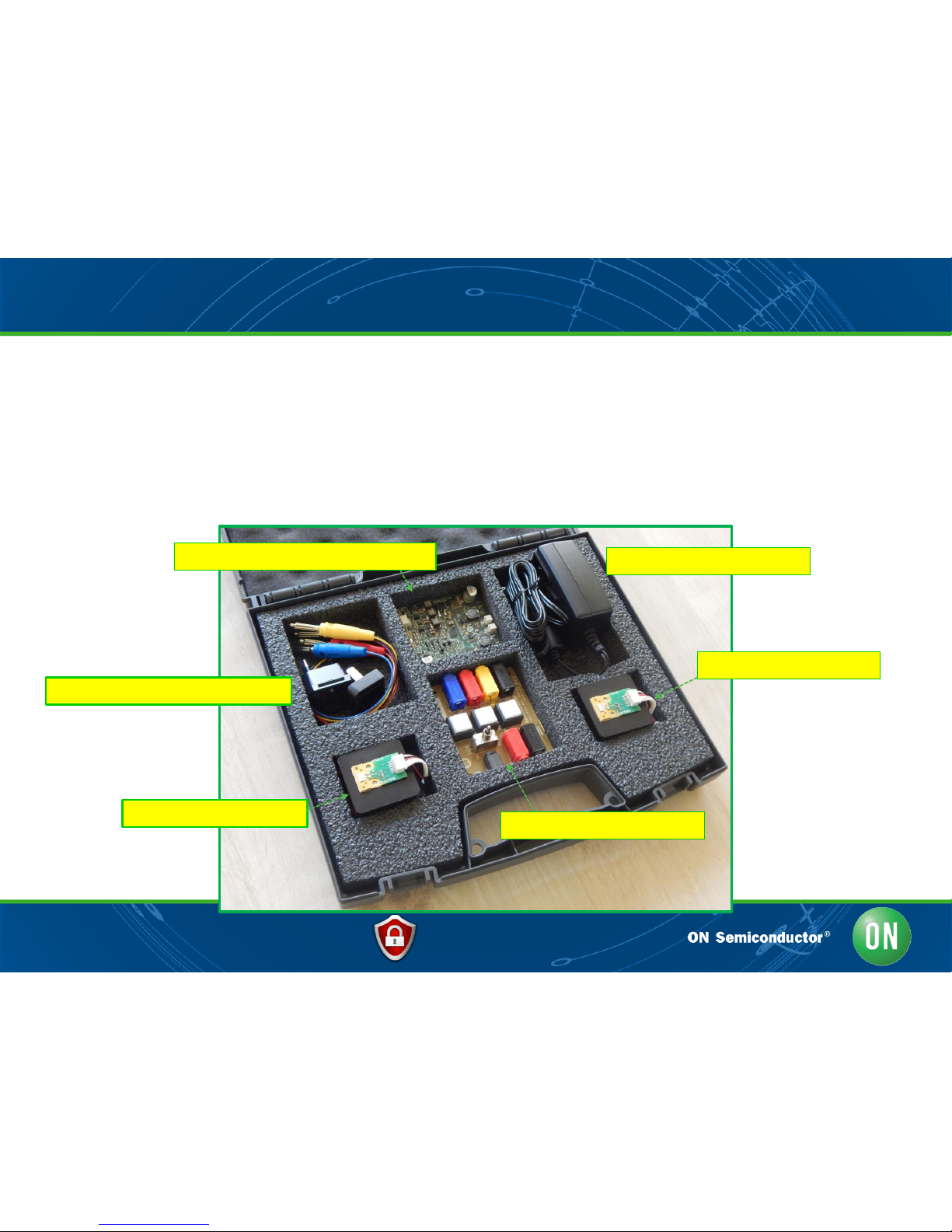
NCV78763 REF DES LDM A – KIT OVERVIEW
(A) NCV78763 REF Design LDM A Board
(C) CABLING and INT Socket Adaptors
(E1) Power LED Module 01
(E2) Power LED Module 02
(B) LDM Interface connection
(D) Wall socket power supply
Page 4
Confidential 4 29/08/2016
NCV78763 REF DES LDM A – Main Features sheet
• The NCV78763 REF Design LDM A system solution is based on the
NCV78763 Power LED Driver for Front Lighting (APG/AAB BU), with a full
ONSEMI BOM portfolio for external power devices.
• The module features failure diagnostics as open load detection, short circuit
protection and thermal protection lock out. A low pin count 8-bit microcontroller
is embedded on board for such monitoring and control.
• The LED strings (DRL/PL) are driven according to advanced dimming control
techniques including logarithmic ramps analog and digital modulation for
enhanced human eye sensitivity smoothness perception. The implementation
fully exploits the SPI bus and LED Driver settings.
• Other key characteristics of the NCV78763 LDM A include: compact
electronics, compatibility target with automotive bulb architectures and
ONSEMI Platform design approach for:
a) Compatibility with a wide range of LED strings configuration without BOM change
b) Easily customizable to the specific system requirements.
c) Wide supply VBAT Operating range from 5V to 20V or higher.
Page 5
Confidential 5 29/08/2016
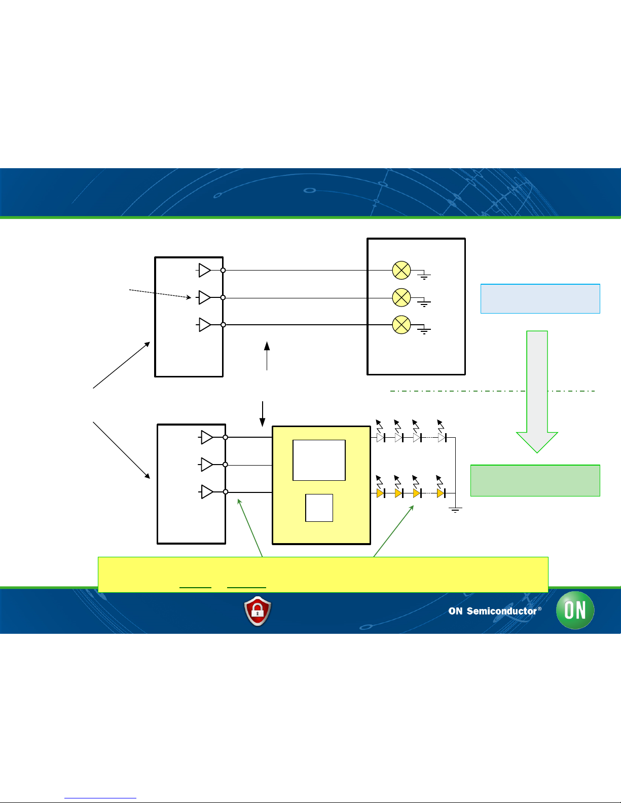
NCV78763 REF DES LDM A & Bulb Systems Compatibility
Body Control Unit
Each line is: Power + Control
+ Diagnostics (current feedback)
Body Control Unit
DRL
PL
TURN
LDM A Reference Design
NCV78763
ONSEMI BOM
DRL + PL
TURN
8-bit
MCU
Diagnostics is performed by
current sensing in the ECU
NCV78763 LDM A as Bulb to LED migration adaptor
The module inputs to outputs functionality is configurable via the embedded MCU
Former Car Front Light
Bulb System
NEW LED Front Lighting
System
Body Light Control by
SWITCHES / SMARTFETs
Migration via LDM adaptor
Page 6
Confidential 6 29/08/2016
NCV78763 LDM A
v1.1
Quick Start Guide
HW SETUP
Page 7
Confidential 7 29/08/2016
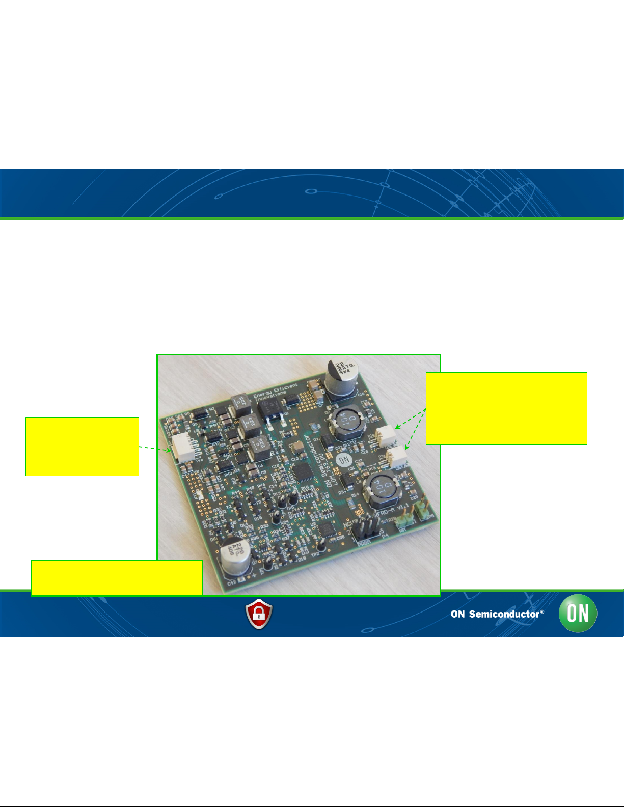
• The NCV78763 LDM A Board, core of the system, is shown hereby. Its BOM is
sized to allow the outputs to drive LED strings for a total power of above 20W
and up to 60V voltage.
• LED Chan 01 is dedicated to DRL and PL, controlled via logarithmic dimming
slopes ramp, while channel 02 performs the turn indicator (blinker) function.
NCV78763 LDM A REF DES KIT: Main board LDM
NCV78763 LDM A – REF Design
Board (KIT ITEM A)
Twice-Two wires output connectors:
Output 01: HOT/ANODE (RED)
Output 01: GND/CATHODE (BLACK)
Output 02: HOT/ANODE (RED)
Output 02: GND/CATHODE (BLACK)
Four ways input connector
Input 01: DRL
Input 02: PL
Input 03: TURN
Input 04: GND
Page 8
Confidential 8 29/08/2016
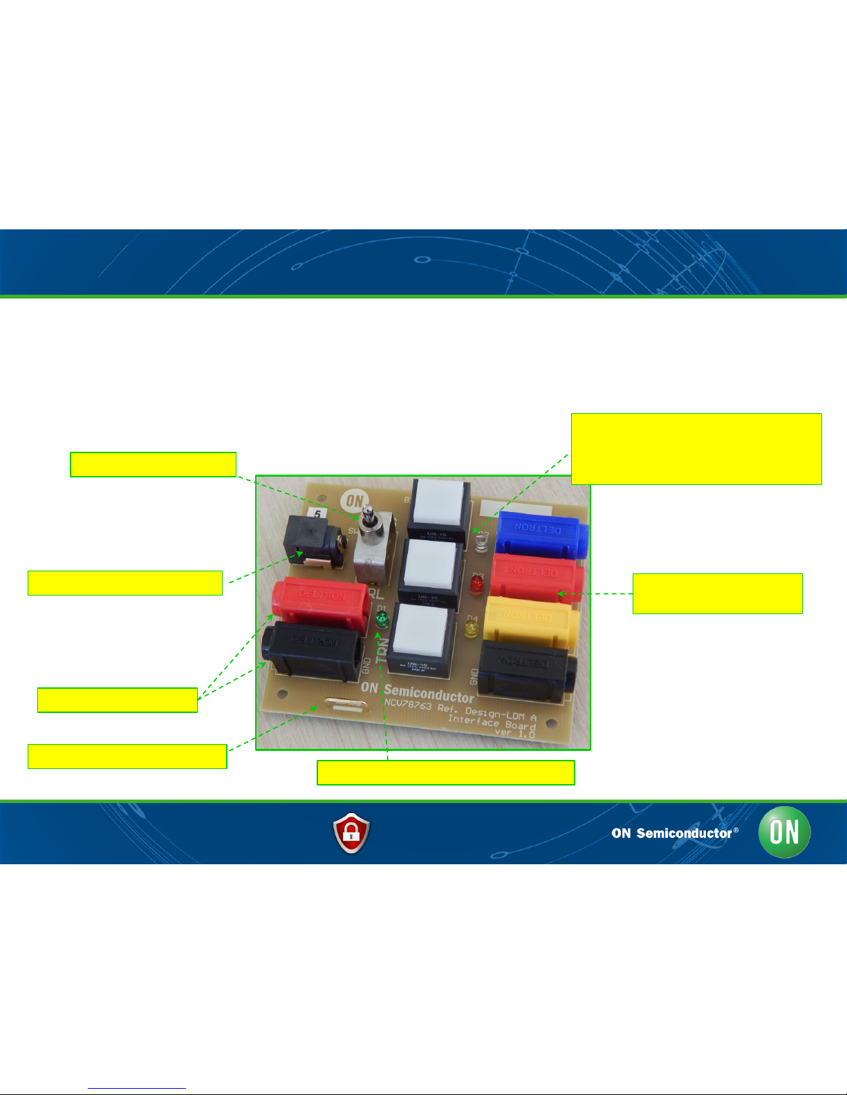
• The LDM REF Design A Interface (ITEM B) grants additional flexibility
for use of an wall socket power supply and allows straightforward
commands by the user via buttons and switch.
NCV78763 LDM A REF DES KIT: the LDM Interface
Plugs towards LDM A - four
wire input interface
Wall socket – Light power supply
LAB Bench power supply
BUTTONS & spy LEDS
1: LDM INPUT 02 / POSITION LIGHT / BLUE
2: LDM INPUT 01 / DRL / RED
3: LDM INPUT 03 / TURN / YELLOW
General “power available” LED
GND bar for oscilloscope probe(s)
SWITCH – PL/ DRL/OPEN
Page 9
Confidential 9 29/08/2016
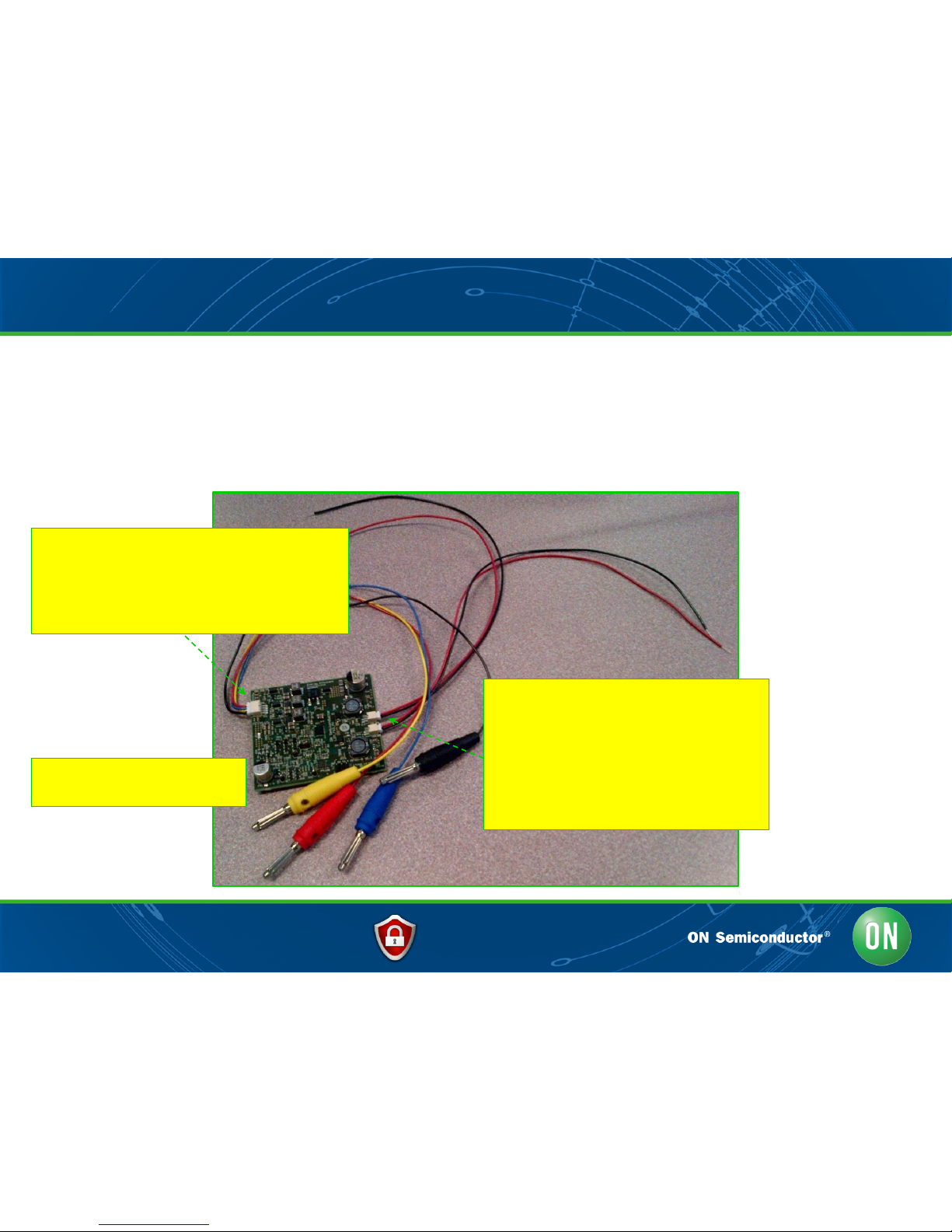
• The NCV78763 LDM A KIT modules come equipped with cabling (KIT
ITEM C) for easy interface towards a standard bench power supply or
the official LDM REF Design A interface (KIT ITEM B):
NCV78763 LDM A REF DES KIT: Cabling & connections
Four wires input connector (KIT ITEM C)
Input 01 / DRL (RED wire & banana)
Input 02 / PL (BLUE wire & banana)
Input 03 / TURN (YELLOW wire & banana)
Input 04 / GND (BLACK wire & banana)
Twice-Two wires output connectors,
connected to LED modules:
Output 01: HOT/ANODE (RED)
Output 01: GND/CATHODE (BLACK)
Output 02: HOT/ANODE (RED)
Output 02: GND/CATHODE (BLACK)
NCV78763 LDM A – REF Des
Board (KIT ITEM A)
Page 10
Confidential 10 29/08/2016
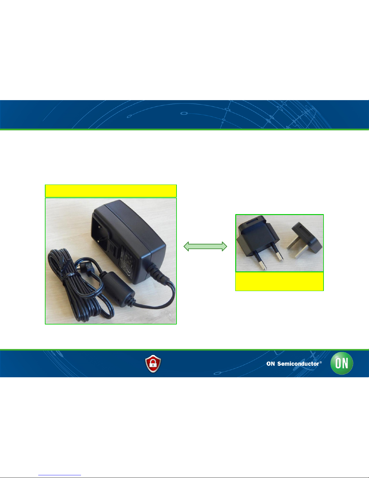
• The provided power supply can be directly plugged in the LDM interface, in
absence of a bench power supply, or for highly portable ready-to-go demos.
NCV78763 LDM A REF DES KIT: Power Supply and plug adapters
12V/3A light power supply – KIT ITEM D
Flexible overall use wall socket
adaptation (E.G. EU/US plugs)
Page 11
Confidential 11 29/08/2016
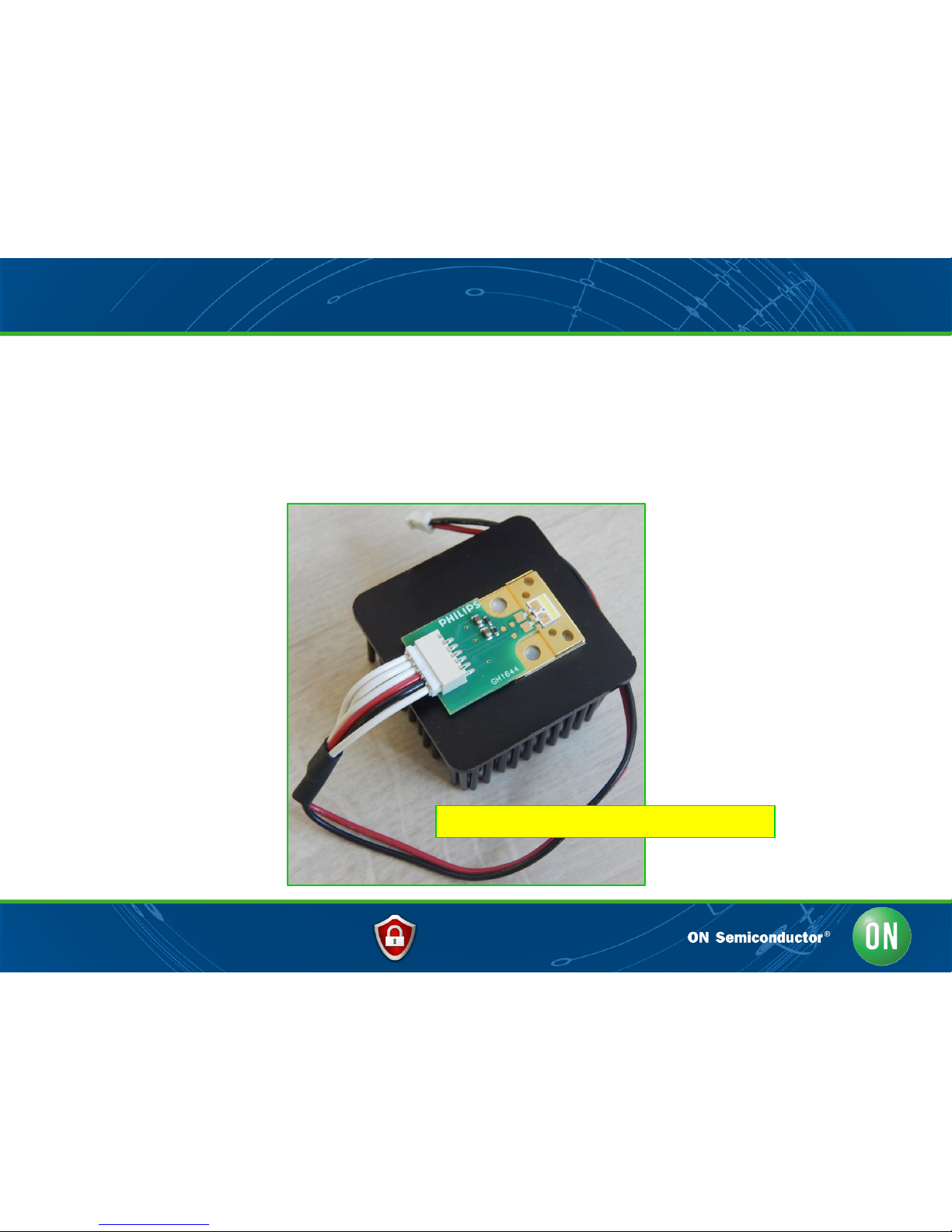
• For reference and immediate use, the KIT contains commercial Automotive
LED Modules (Philips – GH1644). Two samples are available per KIT. The LED
plates are equipped a customized compact heatsink and cabling to be
plugged to the NCV78763 LDM A.
NCV78763 LDM A REF DES KIT: Power LED Modules
Power LED Modules – KIT ITEMS E1/E2
Page 12
Confidential 12 29/08/2016
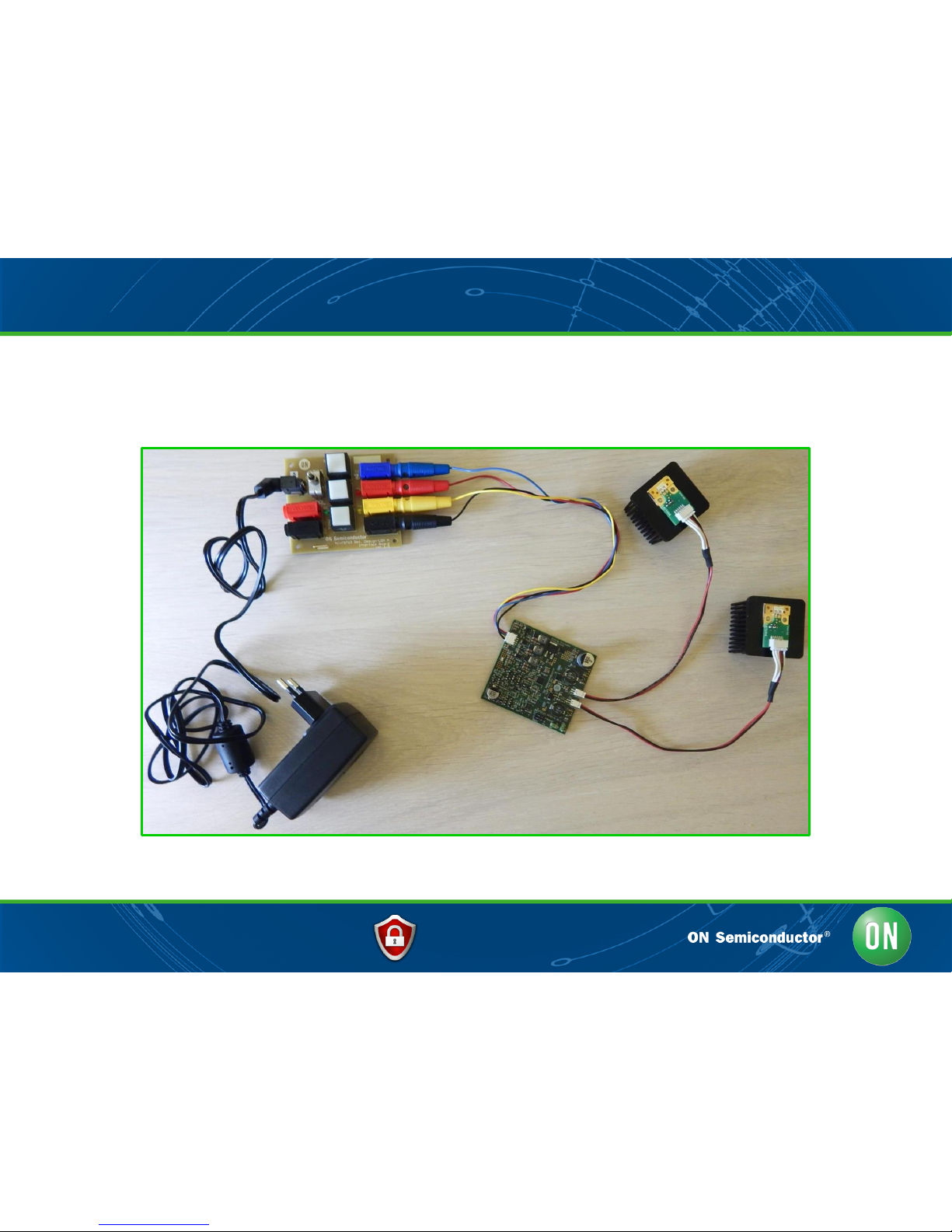
• The connections of all previous elements brings to the following:
NCV78763 LDM A REF DES KIT: the entire setup system
Page 13

Confidential 13 29/08/2016
• The standard factory firmware is set to drive the default KIT LED modules, for
10W power in steady state (around 580mA DC current). Using a different LED
string below 22V, the same current will be applied.
• The system embeds enhanced feature, allowing to adapt parameters to
completely different string and/or headlight per means of the programmer
shown (APRGM). The current levels for channels 01 and 02 are adjusted via
the two respective trimmers. The microcontroller takes care of safety related
items such as power level and voltage adjustments, current limitation and
EEPROM memory save.
NCV78763 LDM A REF DES KIT: The APRGM (optional)
NCV78763 LDM A – APRGM
(KIT ITEM G, optional)
Page 14

Confidential 14 29/08/2016
• In order to allow the current and LED strings programming procedure, the
APRGM board, when the system is in power off, must first be plugged into the
three LDM A main board connectors “P4” “S1” and “P5” (respectively CN1,
CN2 and CN3 in APRGM).
NCV78763 LDM A REF DES KIT: APRGM – Setup
NCV78763 LDM A – APRGM: LED current programming procedure setup
Page 15

Confidential 15 29/08/2016
• After setup, the LED current programming procedure is actually entered when,
powering up the system, the button S3 is kept pressed. Details on the procedure are
reported below.
1. When entering programming procedure, the LED DS1 will start blinking. Release
button S3. Before driving current into the LED strings, the microcontroller will wait that
the user brings the trimmers P1 and P2 (current setting knobs) to the left most
position (counter-clock-wise) to preselect the minimum current level: whenever this
position is attained, the LDM will drive currents in both LED strings. At any time, the
sequence can be exited without save by pressing “S2”;
2. Adjust the current in the LEDs. The right setting can be found by human visual
perception such as lighting of a dark room (never look directly in the LED source to
potential avoid health hazard or dazzling!), light intensity measurement, a current
measurement probe, or series multimeter in current sensing mode;
3. Once the desired current is found, new settings are save by pressing “S1”;
4. As an alternative, original factory settings can always be restored with the“S3” button.
Please note that any LED string between 2V and 60V can be used. The firmware will limit
the current so that 10W maximum per channel can be delivered.
NCV78763 LDM A REF DES KIT: APRGM – Procedure #1
Page 16

Confidential 16 29/08/2016
• Please refer to the following picture for a graphical explanation of the LED
current setting programming procedure.
Button S3:
- Enter procedure while powering up
- Save factory settings when programming procedure is running
Button S2:
- Exit immediately without saving when programming procedure is running
Button S1:
- Exit programming feature and Save new user settings
LED DS1:
- User feedback (blink code)
NCV78763 LDM A REF DES KIT: APRGM – Procedure #2
Trimmer P1 & P2:
LED Chan 01 & 02 settings
Page 17

Confidential 17 29/08/2016
NCV78763 LDM A
v1.1
System Overview
Design
Page 18

Confidential 18 29/08/2016
NCV78763 LDM A REF DES: PCB Board 3D Overview
NCV78763 LDM A 3D image - PCB Size: 68mm xx 63mm
Page 19

Confidential 19 29/08/2016
NCV78763 LDM A REF DES: Schematics (top-level view)
The LDM A REF DES v1.1 top level block schematics view is shown below:
(A) INPUTS (POWER & SIGNALS)
(B) REVERSE POLARITY PROTECTION
(C) MCU INPUTS INTERFACE
(D) MCU (LOW COST LOW PIN COUNT)
(E) NCV78763 LED DRIVER
BODY CONTROLLER
DRL/PL LED STRING
TURN LED STRING
DIAGNOSTIC OUTAGE
Page 20

Confidential 20 29/08/2016
NCV78763 LDM A REF DES: sub-circuit #B: reverse battery
Page 21

Confidential 21 29/08/2016
NCV78763 LDM A REF DES: sub-circuit #C: MCU interface
Page 22

Confidential 22 29/08/2016
NCV78763 LDM A REF DES: sub-circuit #D: MCU
Page 23

Confidential 23 29/08/2016
NCV78763 LDM A REF DES: sub-circuit #E: NCV78763
Page 24

Confidential 24 29/08/2016
NCV78763 LDM A REF DES: PCB (top side)
Page 25

Confidential 25 29/08/2016
NCV78763 LDM A
v1.1
System Overview
Measurement
Report
Page 26

Confidential 26 29/08/2016
Measurement report: DRL ramp turn-on
• At power on (line #1 = DRL input), the DRL led string is ramped to the nominal current
value by combining analog and digital dimming (logarithmic mode is shown).
1: Analog dimming ramp phase (amplitude logarithmic increases)
2: Digital dimming ramp phase (duty cycle logarithmic increases)
3: Constant current phase
DRL input turn ON
Page 27

Confidential 27 29/08/2016
System steady state stability (low VBAT = 7V)
Page 28

Confidential 28 29/08/2016
System steady state stability (nom VBAT = 13V)
Page 29

Confidential 29 29/08/2016
System steady state stability (nom VBAT = 19V)
Page 30

Confidential 30 29/08/2016
PSRR stability (VBAT = 10V >>> 20V)
The LED current is not affected by harsh battery step-ups
Page 31

Confidential 31 29/08/2016
PSRR stability (VBAT = 20V >>> 10V)
Also in case of heavy battery drops the LED current is not affected
Page 32

Confidential 32 29/08/2016
Diagnostic & specific input turn-off
• In this diagnostic detection example, the output VLED is shorted to GND.
• The module turns off the input to flag to the body controller the failure.
Programmed short circuit detection time
Short circuit: VLED → 0V
Failing input is forced off by the related
module switch (MCU keeps stand by)
Current in the DRL string goes to zero
(the whole current flows in the short)
Page 33

Confidential 33 29/08/2016
ISO 7637 pulses (type 1)
• The LDM A module is validated through the standard ISO 7637 pulses. For what
concerns pulse type 1, it is shown how it correctly restarts normal operation at
each pulse iteration.
Page 34

Confidential 34 29/08/2016
ISO 7637 pulses (type 1 - ZOOM)
• The module correctly restarts normal operation at each pulse iteration.
Note: No reset from the MCU.
Page 35

Confidential 35 29/08/2016
ISO 7637 pulses (type 2a)
• Also in this case, the module correctly restarts normal operation at each
pulse iteration.
Page 36

Confidential 36 29/08/2016
ISO 7637 pulses (type 3a)
• The highest amplitude disturbance (-150V) does not minimally affect the
module operation.
Page 37

Confidential 37 29/08/2016
ISO 7637 pulses (type 3b)
• The highest disturbance (+150V) does not affect at all the module operation.
Page 38

Confidential 38 29/08/2016
EMC conducted emission CISPR25
Results obtained without EMC input filter
(small X7R capacitor only used)
Page 39

Confidential
LED FRONTLIGHTING SOLUTIONS AAB
NCV78763 LDM A – QUICK START GUIDE - OVERVIEW
Any question or advice?
Our staff will be glad to provide all necessary information and collect
your valuable inputs.
Page 40

Mouser Electronics
Authorized Distributor
Click to View Pricing, Inventory, Delivery & Lifecycle Information:
ON Semiconductor:
NV78763RLA11GEVK
 Loading...