

Page 1

User’s Guide to Powering Up and Using the NCP3284 Evaluation Board,
Rev. D
This guide is intended to assist those using the NCP3284 Evaluation Board, Rev. D. It will
provide useful tips and procedures for powering up and using the Evaluation Board (EVB).
Description – The NCP3284 Evaluation Board Rev. D is a test vehicle for the NCP3284 singlephase point-of-load (POL) voltage regulator. The printed circuit board assembly (PCBA)
contains all the circuitry and connections necessary to evaluate the performance of the NCP3284
under various load and system conditions.
Page 2
User’s Guide to Powering Up and Using the NCP3284 Evaluation Board,
Rev. D
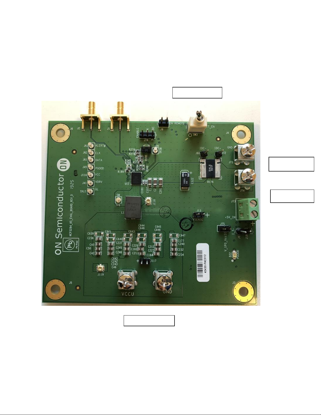
Photo of NCP3284 EVB
Input Power
+5 V power
Page 3

User’s Guide to Powering Up and Using the NCP3284 Evaluation Board,
Rev. D
Connection instructions – The EVB has a basic connection scheme independent of how the
device is powered. The terminals labeled “Input Power” are for the input voltage rail, sometimes
called Input Voltage, VBAT or battery voltage. This is the high voltage rail (~6 V to 18 V) for
the input of the regulator. (Cables capable of high current with low voltage drop are required to
test this board).
There is a second pair of power input terminals (Logic Power in the photo) which requires +5 V.
This is intended for powering various logic and LDO circuits on the EVB, independently of the
input power and the device LDO (VDRV in the schematic).
In general, then, connect the battery voltage to Input Power and +5 V to Logic Power. Set the
initial current limit for each supply to 1 A, or less. In both cases, the minus, or ground,
terminal is the top position and the plus terminal is the bottom position.
The EVB has one 3-pin header, J78, which configures the enable functionality of the EVB. We
recommend that the jumper be set so that pins 2 and 3 (left two pins) of J78 are shorted (default
condition). This configures the enable switch (SW3) to be the default method for starting the
EVB. The other method of enabling the device is to have the board enable as the input power is
applied, via the voltage divider set by R131 and R130. This is accomplished by moving the
jumper position of J78 to pins 1 and 2 (right two pins).
Once the power inputs and enabling scheme have been set up, apply power and toggle the enable
switch (if used) and the EVB should power up and the green LED indicating PGOOD should
light.
Page 4

User’s Guide to Powering Up and Using the NCP3284 Evaluation Board,
Rev. D
Connection instructions, cont. – Check to see that the output is 1.000 V±5 mV, or better. The
switching frequency seen on an oscilloscope should be approximately 550 to 600 kHz in Forced
CCM mode (FCCM).
If the board powers up successfully, at this time you can increase the current limit of the
supplies. At 1 V output, the minimum current required from the input power supply is 3 A for a
25 to 30 A load. The input power supply current limit should be set at 5 amps in order to test the
OCP of the board. For the logic power, the current limit can be left at 1 A.
Loading the output and checking over-current protection (OCP) - Connect a suitable
electronic load to the output terminals. The electronic load should be capable of sinking at least
40 A at an input voltage at the load terminals of 1 V, or less. As pre-configured, the OCP
threshold of the EVB is 33 A at the valley of the inductor ripple. This translates to 36-37 A DC
at the output terminals. As the OCP threshold is approached, the switch node waveform will
change frequency noticeably, until the OCP trigger point is reached. Once the protection is
triggered, the board will latch off, and can only be restarted by removing the load and either
cycling the input voltage or toggling the enable switch, depending on which method was used to
enable the EVB.
This ends this description of the NCP3284 BGA359 EVB. If you have questions, please contact
Antonio Germano, by one of the following methods.
antonio.germano@onsemi.com
1-408-822-2834
Or, contact the P2 Applications Manager, George Feng:
George.feng@onsemi.com
1-408-822-2867
 Loading...