

Page 1
Isolated Compact IGBT
Gate Driver with Current Sense
NCD57085, NCV57085
NCx57085 is a high current single channel IGBT gate driver
with 2.5 kVrms internal galvanic isolation designed for high system
efficiency and reliability in high power applications. The driver
includes Current Sense function with soft turn off and fault reporting
in a narrow body SOIC*8 package. NCx57085 accommodates wide
range of input bias voltage and signal levels from 3.3 V to 20 V,
and wide range of output bias voltage up to 30 V.
Features
• High Peak Output Current (+7A/−7 A)
• Low Output Impedance for Enhanced IGBT Driving
• Short Propagation Delays with Accurate Matching
• IGBT Over Current Protection
• Negative Voltage (Down to −9 V) Capability for CS Pin
• IGBT Gate Clamping during Short Circuit
• IGBT Gate Active Pull Down
• Soft Turn Off During IGBT Over Current
• Tight UVLO Thresholds for Bias Flexibility
• Output Partial Pulse Avoidance During UVLO/CS (Restart)
• 3.3. V, 5 V, and 15 V Logic Input
• 2.5 kVrms Galvanic Isolation
• High Transient Immunity
• High Electromagnetic Immunity
• NCV Prefix for Automotive and Other Applications Requiring
Unique Site and Control Change Requirements;
AEC−Q100 Qualified and PPAP Capable
• This Device is Pb−Free, Halogen Free/BFR Free and is RoHS
Compliant
Typical Applications
• Motor Control
• Automotive Applications
• Uninterruptible Power Supplies (UPS)
• Industrial Power Supplies
• HVAC
• Industrial Pumps and Fans
• PTC Heater
www.onsemi.com
8
1
SOIC−8 NB
CASE 751−07
MARKING DIAGRAM
8
57085
ALYW
G
1
57085 = Specific Device Code
A = Assembly Location
L = Wafer Lot
Y = Year
W = Work Week
G = Pb−Free Package
PIN CONNECTIONS
1
VDD
2
IN
3
FLT
4
GND
NCx57085
x = D or V
ORDERING INFORMATION
See detailed ordering and shipping information on page 12 of
this data sheet.
8
V
B
7
HO
6
CS
5
V
S
© Semiconductor Components Industries, LLC, 2021
March, 2021 − Rev. 0
1 Publication Order Number:
NCD57085/D
Page 2
NCD57085, NCV57085
IN
FLT
GND
VCC1
VDD
UVLO1
VB
UVLO2
LogicLogic
STO
VS
VB
+
−
V
CS−THR
HO
CS
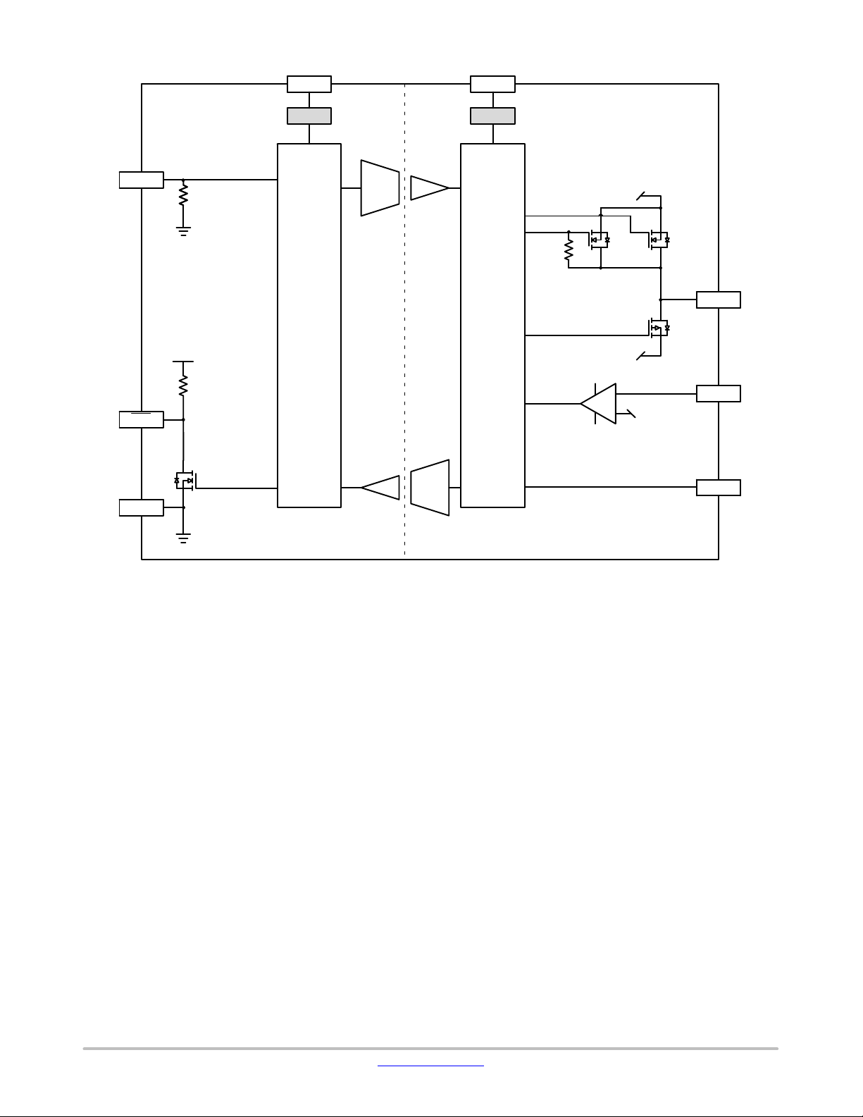
VS
Figure 1. Simplified Block Diagram
www.onsemi.com
2
Page 3
NCD57085, NCV57085
V
DD
V
DD
IN
FLT
HO
CS
GND
V
B
V
B
V
S
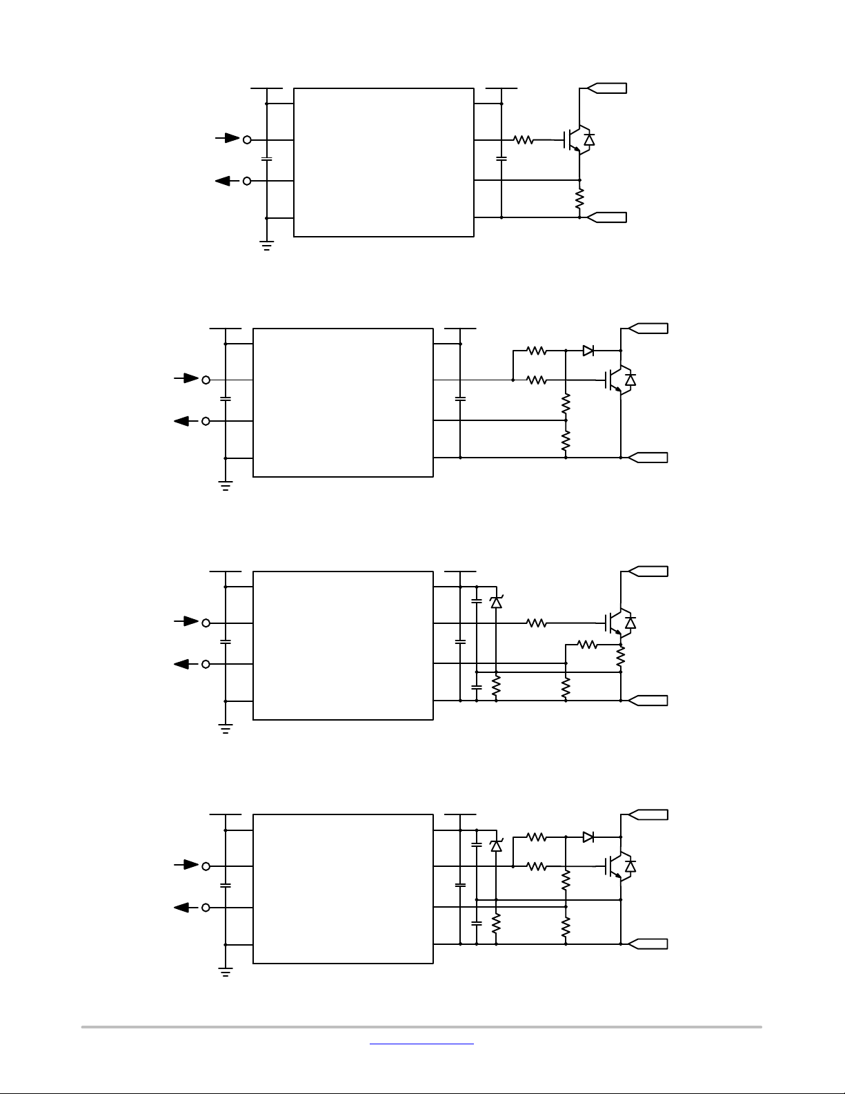
Figure 2. Simplified Application Schematics, Current Sense Using Shunt Resistor
V
DD
V
DD
IN
FLT
HO
CS
GND
V
B
V
B
V
S
Figure 3. Simplified Application Schematics, Current Sense Using IGBT Vce
V
DD
V
DD
IN
FLT
GND
V
HO
CS
V
V
B
B
S
Figure 4. Simplified Application Schematics, Current Sense Using Shunt Resistor and Negative Gate Drive
V
DD
V
DD
V
HOIN
FLT
CS
V
B
B
GND
V
S
Figure 5. Simplified Application Schematics, Current Sense Using IGBT Vce and Negative Gate Drive
www.onsemi.com
3
Page 4
NCD57085, NCV57085
FUNCTION DESCRIPTION
Pin Name No. I/O Description
V
DD
1 Power
IN 2 I
Input side power supply. A good quality bypassing capacitor is required from this pin to
GND and should be placed close to the pins for best results.
The under voltage lockout (UVLO) circuit enables the device to operate at power on when
a typical supply voltage higher than V
more details.
UVLO1−OUT−ON
Non−inverted gate driver input. The equivalent input pull down resistance is about 100 kW
when the input voltage is below 5.5 V. The input adapter circuitry will work once the input
voltage is higher than 5.5 V, and will keep the input current at the level when the input voltage is 5.5 V even though it is higher than that. A minimum pulse width is required at IN
before HO responds.
is present. Please see Figure 7 for
FLT 3 O
Fault output (active low) that allows communication to the main controller that the driver
has encountered a Over Current, or UVLO1, or UVLO2 condition and has deactivated the
output. There is an internal 50 kW pull−up resistor connected to this pin. Multiple of them
from different drivers can be “OR”ed together.
/FLT and HO will go high automatically after t
avoid partial output pulse on HO. This is a feature called “Re−start”.
expires along with a rising edge of IN to
MUTE
GND 4 Power Input side ground reference.
V
S
CS 6 I/O
5 Power Output side ground reference.
Input for detecting over current of IGBT. The current sense threshold has to be met uninterruptedly for a fixed period of t
9 and Figure 10.
FLT
and HO will be kept low (including soft turn off time) at least for a period defined by
t
.
MUTE
before HO and /FLT are set low. Please refer to Figure
FILTER
HO 7 O Driver output that provides the appropriate drive voltage and source/sink current to the
IGBT/FET gate. HO is actively pulled low during start−up.
V
B
8 Power
Output side positive power supply. The operating range for this pin is from UVLO2 to its
maximum allowed value. A good quality bypassing capacitor is required from this pin to V
and should be placed close to the pins for best results.
The under voltage lockout (UVLO) circuit enables the device to operate at power on when
a typical supply voltage higher than V
more details.
UVLO2−OUT−ON
is present. Please see Figure 8 for
S
www.onsemi.com
4
Page 5
NCD57085, NCV57085
SAFETY AND INSULATION RATINGS
Symbol
Installation Classifications per DIN VDE 0110/1.89
Table 1 Rated Mains Voltage
Climatic Classification 40/100/21
Pollution Degree (DIN VDE 0110/1.89) 2
CTI Comparative Tracking Index (DIN IEC 112/VDE 0303 Part 1) 600
V
V
IORM
V
IOWM
V
E
E
PR
IOTM
CR
CL
Input−to−Output Test Voltage, Method B, V
100% Production Test with t
= 1 s, Partial Discharge < 5 pC
m
Maximum Repetitive Peak Voltage 1200 V
Maximum Working Insulation Voltage 870 V
Highest Allowable Over Voltage 4200 V
External Creepage 4.0 mm
External Clearance 4.0 mm
DTI Insulation Thickness 8.65
T
Case
P
S,INPUT
P
S,OUTPUT
R
IO
Safety Limit Values – Maximum Values in Failure; Case Temperature 150 °C
Safety Limit Values – Maximum Values in Failure; Input Power 132 mW
Safety Limit Values – Maximum Values in Failure; Output Power 1128 mW
Insulation Resistance at TS, V
IO
Parameter Value Unit
< 150 V
RMS
< 300 V
RMS
< 450 V
RMS
< 600 V
RMS
× 1.875 = VPR,
IORM
< 1000 V
RMS
= 500 V 10
I−IV
I−IV
I−IV
I−IV
I−III
2250 V
9
PK
PK
RMS
PK
mm
W
ISOLATION CHARACTERISTICS
Symbol Parameter Conditions Value Unit
V
ISO,
INPUT− OUTPUT
R
ISO
1. Device is considered a two−terminal device: pins 1 to 4 are shorted together and pins 5 to 8 are shorted together.
2. 2,500 VRMS for 1−minute duration is equivalent to 3,000 VRMS for 1−second duration.
3. The input−output isolation voltage is a dielectric voltage rating per UL1577. It should not be regarded as an input−output continuous voltage
rating. For the continuous working voltage rating, refer to equipment−level safety specification or DIN VDE V 0884−11 Safety and Insulation
Ratings Table.
Input−Output Isolation Voltage TA = 25°C, Relative Humidity < 50%, t = 1.0 minute,
< 30 mA, 50 Hz
I
I−O
(Notes 1, 2, 3)
Isolation Resistance V
= 500 V (Note 1) 10
I−O
2500 V
11
RMS
W
www.onsemi.com
5
Page 6
NCD57085, NCV57085
ABSOLUTE MAXIMUM RATINGS (Note 4) Over operating free−air temperature range unless otherwise noted.
Symbol
V
− GND Supply Voltage, Input Side −0.3 22 V
DD
V
− V
B
VHO − V
I
PK−SRC
S
S
Supply Voltage, Output Side −0.3 32 V
Gate−driver Output Voltage −0.3 VBS + 0.3 V
Gate−driver Output Sourcing Current
(maximum pulse width = 10 ms, maximum duty cycle = 0.2%,
V
− VS = 15 V)
D
I
PK−SNK
Gate−driver Output Sinking Current
(maximum pulse width = 10 ms, maximum duty cycle = 0.2%,
V
− VS = 15 V)
D
V
− GND Voltage at IN, FLT −0.3 VDD + 0.3 V
IN
IFLT Output current of FLT − 10 mA
VCS − V
S
Voltage at CS (Note 5) −9 VBS + 0.3 V
PD Power Dissipation (Note 6) − 1123 mW
ESD
ESD
HBM
CDM
ESD Capability, Human Body Model (Note 7) − ± 2 kV
ESD Capability, Charged Device Model (Note 7) − ± 2 kV
MSL Moisture Sensitivity Level − 1 −
TJ(max) Maximum Junction Temperature −40 150 °C
TSTG Storage Temperature Range −65 150 °C
TSLD Lead Temperature Soldering Reflow, Pb−Free (Note 8) − 260 °C
Stresses exceeding those listed in the Maximum Ratings table may damage the device. If any of these limits are exceeded, device functionality
should not be assumed, damage may occur and reliability may be affected.
4. Refer to ELECTRICAL CHARACTERISTICS and APPLICATION INFORMATION for Safe Operating Area.
5. The minimum value is verified by characterization with a single pulse of 1.5 mA for 300 ms.
6. The value is estimated for ambient temperature 25°C and junction temperature 150°C, 650 mm
power plane layers. Power dissipation is affected by the PCB design and ambient temperature.
7. This device series incorporates ESD protection and is tested by the following methods:
ESD Human Body Model tested per AEC−Q100−002 (EIA/JESD22−A114).
ESD Charged Device Model tested per AEC−Q100−011 (EIA/JESD22−C101).
Latchup Current Maximum Rating: ≤100 mA per JEDEC standard: JESD78, 125°C.
8. For information, please refer to our Soldering and Mounting Techniques Reference Manual, SOLDERRM/D.
Parameter Minimum Maximum Unit
− 7 A
− 7.5 A
2
, 1 oz copper, 2 surface layers and 2 internal
THERMAL CHARACTERISTICS
Symbol Parameter Conditions Value Unit
R
θ
Thermal Resistance, Junction−to−Air
JA
100 mm2, 1 oz Copper, 1 Surface Layer
100 mm2, 1 oz Copper, 2 Surface Layers and 2
179
110
°C/W
Internal Power Plane Layers
9. Refer to ELECTRICAL CHARACTERISTICS and APPLICATION INFORMATION for Safe Operating Area.
10.Values based on copper area of 100 mm
2
(or 0.16 in2) of 1 oz copper thickness and FR4 PCB substrate.
OPERATING RANGES (Note 11)
Symbol Parameter Min Max Unit
VDD−GND Supply Voltage, Input Side UVLO1 20 V
VB−V
S
V
IN
|dV
/dt| Common Mode Transient Immunity 100 −
ISO
T
A
Supply Voltage, Output Side UVLO2 30 V
Logic Input Voltage at IN GND V
DD
kV/ms
Ambient Temperature −40 125 °C
V
Functional operation above the stresses listed in the Recommended Operating Ranges is not implied. Extended exposure to stresses beyond
the Recommended Operating Ranges limits may affect device reliability.
11.Refer to ELECTRICAL CHARACTERISTICS and APPLICATION INFORMATION for Safe Operating Area.
www.onsemi.com
6
Page 7
NCD57085, NCV57085
ELECTRICAL CHARACTERISTICS V
For typical values T
Symbol
VOLTAGE SUPPLY
V
UVLO1−OUT−ON
V
UVLO1−OUT−OFF
V
UVLO1−HYST
V
UVLO2−OUT−ON
V
UVLO2−OUT−OFF
V
UVLO2−HYST
I
DD−0−3.3
I
DD−0−5
I
DD−0−15
I
DD−100−5
I
BS−0
I
BS−100
LOGIC INPUT AND OUTPUT
V
IL
V
IH
V
IN−HYST
I
IN
I
FLT−L
V
FLT−L
t
MIN1
t
MIN2
DRIVER OUTPUT
V
HOL1
V
HOL2
V
HOH1
V
HOH2
I
PK−SNK1
I
PK−SNK2
I
PK−SRC1
I
PK−SRC2
OVER CURRENT PROTECTION
V
CS−THR
V
CS−NEG
= 25°C, for min/max values, TA is the operating ambient temperature range that applies, unless otherwise noted.
A
Parameter Test Conditions Min Typ Max Unit
UVLO1 Output Enabled − − 3.1 V
UVLO1 Output Disabled 2.4 − − V
UVLO1 Hysteresis 0.1 − − V
UVLO2 Output Enabled 12.4 12.9 13.4 V
UVLO2 Output Disabled 11.5 12 12.5 V
UVLO2 Hysteresis 0.7 1 − V
Input Supply Quiescent Current
Output Supply Quiescent Current
Low Input Voltage (Note 12) 1.65 V
High Input Voltage (Note 12) 0.7 x V
Input Hysteresis Voltage
(Note 12)
Input Current VIN = V
FLT Pull−up Current
(50 kW pull−up resistor)
FLT Low Level Output Voltage I
Input Pulse Width of IN for No Response at Output
Input Pulse Width of IN for
Guaranteed Response at Output
Output Low State
(V
– VS)
HO
Output High State
– VHO)
(V
B
Peak Driver Current, Sink
(Note 13)
Peak Driver Current, Sink
(Note 13)
Peak Driver Current, Source
(Note 13)
Peak Driver Current, Source
(Note 13)
CS Threshold Voltage 0.2 0.25 0.3 V
CS Negative Voltage ICS = 1.5 mA − −8 − V
= 5 V, VBS = 15 V.
DD
IN = Low, VDD = 3.3 V, FLT = High − − 2 mA
IN = Low, VDD = 5 V, FLT = High − − 2 mA
IN = Low, VDD = 15 V, FLT = High − − 2 mA
IN = High, VDD = 5 V, FLT = High − − 6 mA
IN = Low, no load − − 4 mA
IN = High, no load − − 6 mA
V
I
I
I
I
VHO = 9 V
(near IGBT Miller Plateau)
VHO = 9 V
(near IGBT Miller Plateau)
DD
0.15 x V
DD
= Low − 100 −
FLT
= 5 mA − − 0.3 V
FLT
50
2.1 V
DD
− − 10 ns
40 − − ns
= 200 mA − 0.1 0.22
SNK
= 1.0 A, TA = 25°C − 0.4 1
SNK
= 200 mA − 0.2 0.35
SRC
= 1.0 A, TA = 25°C − 0.6 1.7
SRC
− 7.5 − A
− 7 − A
− 7 − A
− 5 − A
V
mA
mA
V
V
www.onsemi.com
7
Page 8

NCD57085, NCV57085
ELECTRICAL CHARACTERISTICS V
For typical values T
= 25°C, for min/max values, TA is the operating ambient temperature range that applies, unless otherwise noted.
A
= 5 V, VBS = 15 V.
DD
Symbol UnitMaxTypMinTest ConditionsParameter
IGBT SHORT CIRCUIT CLAMPING
V
CLP−HO
IGBT Short Circuit Clamping (V
− VB)
IN = High, IHO = 500 mA,
HO
t
CLP
= 10 ms
− 0.7 1.5 V
DYNAMIC CHARACTERISTICS
t
PD−ON
IN to HO High Propagation
Delay
C
= 10 Nf
LOAD
VIH to 10% of HO Change
40 60 90 ns
for PW > 150 ns
t
PD−OFF
t
DISTORT
t
DISTORT_TOT
t
RISE
t
FALL
t
LEB
t
FILTER
t
STO
t
FLT
t
FLT1
t
FLT2
t
MUTE
t
UVR1
IN to HO Low Propagation Delay C
Propagation Delay Distortion
(= t
PD−ON
− t
PD−OFF
)
Prop Delay Distortion between
Parts
Rise Time (see Figure 6)
(Note 13)
Fall Time (see Figure 6)
(Note 13)
CS Leading Edge Blanking Time
(See Figure 9 and Figure 10)
CS Threshold Filtering Time
(see Figure 9 and Figure 10)
Soft Turn Off Time
(see Figure 9 and Figure 10)
Delay after t
Delay from V
Triggered to FLT
Delay from t
IN Mute Time after t
UVLO1, UVLO2 Triggered
Delay from V
Triggered to HO High
to FLT Low 100 450 700 ns
FILTER
UVLO1−OUT−OFF
Low
to FLT Low − 2.4 −
UV2F
FILTER
UVLO1−OUT−ON
, or
= 10 nF
LOAD
V
to 90% of HO Change
IL
for PW > 150 ns
TA = 25°C, PW > 150 ns − 0 −
40 60 90 ns
ns
TA = −40°C to 125°C, PW > 150 ns −25 − 25
PW > 150 ns −30 0 30 ns
C
= 1 nF, 10% to 90%
LOAD
of HO Change
C
= 1 nF, 90% to 10%
LOAD
of HO Change
− 10 − ns
− 15 − ns
200 450 700 ns
− 600 700 ns
C
= 10 nF, RG = 10 W
LOAD
1.2 1.8 3
ms
− 1.5 − ns
ms
20 − −
ms
(Note 13) − 770 − ns
(see Figure 7)
t
UVF1
Delay from V
Triggered to HO Low
UVLO1−OUT−OFF
(Note 13) − 1500 − ns
(see Figure 7)
t
UVR2
Delay from V
Triggered to HO High
UVLO2−OUT−ON
(Note 13) − 1000 − ns
(see Figure 8)
t
UVF2
Delay from V
Triggered to HO Low
UVLO2−OUT−OFF
(Note 13) − 1000 − ns
(see Figure 8)
Product parametric performance is indicated in the Electrical Characteristics for the listed test conditions, unless otherwise noted. Product
performance may not be indicated by the Electrical Characteristics if operated under different conditions.
12.Table values are valid for 3.3 V and 5 V V
13.Values based on design and/or characterization.
, for higher VDD voltages, the threshold values are maintained at the 5 V VDD levels.
DD
www.onsemi.com
8
Page 9

IN
NCD57085, NCV57085
V
IH
V
IL
t
MIN2
t
PD−ON
HO
V
BS
V
UVLO1−OUT−ON
V
UVLO1−OUT−OFF
V
DD
t
UVR1
t
RISE
t
FALL
90%
t
PD−OFF
10%
Figure 6. Propagation Delay, Rise and Fall Time
t
MUTE
t
UVF1
t
UVR1
t
MUTE
t
UVF1
t
MIN1
t
UVR1
t
MIN1
IN
HO
FLT
t
FLT1
t
FLT1
Figure 7. UVLO1 Waveform
www.onsemi.com
9
Page 10

V
DD
V
UVLO2−OUT−ON
V
UVLO2−OUT−OFF
NCD57085, NCV57085
V
IN
HO
FLT
BS
t
UVR2
t
MUTE
t
UVF2
t
FLT2
t
MUTE
t
t
UVR2
UVF2
Figure 8. UVLO2 Waveform
t
FLT2
t
UVR2
HO
CS
FLT
IN
t
PD−ON
t
LEB
t
MUTE
t
PD−ON
90% HO
10% HO
t
FILTER
t
t
STO
FLT
V
CS−THR
t
FILTER
t
LEB
Figure 9. CS Response Waveform Using IGBT Vce
t
t
FLT
STO
t
MUTE
t
PD−ON
www.onsemi.com
10
Page 11

IN
t
PD−ON
NCD57085, NCV57085
t
MUTE
90% HO
t
PD−ON
t
MUTE
t
PD−ON
HO
CS
FLT
10% HO
t
t
STO
FLT
t
FILTER
t
t
FLT
STO
t
FILTER
t
LEB
Figure 10. CS Response Waveform Using Shunt Resistor
www.onsemi.com
11
Page 12

NCD57085, NCV57085
TRUTH TABLE
IN UVLO1 UVLO2 CS HO FLT Notes
H Inactive Inactive L L L Initial condition after power up VDD and V
↗
H Inactive Inactive L H H Normal Operation − Output High
↘
L Inactive Inactive L L H Normal Operation − Output Low
X Active Inactive X L L UVLO1 Activated − FLT Low (t
↗
X Inactive Active X L L UVLO2 Activated − FLT Low (t
↗
H Inactive Inactive H (>t
↗
Inactive Inactive L
Inactive Inactive L
Inactive Inactive L
Inactive Inactive L
Inactive Inactive L
↗ ↗
↘
↗ ↗
↗ ↗
) L L CS Activated − FLT Low (tFLT), Output Low
FILTER
↗ ↗
Initial condition − IN First Rising edge
H Normal Operation − Turn off Output
FLT1
FLT reset, UVLO1 conditions disappear
FLT1
FLT reset, UVLO2 conditions disappear
FLT reset, CS conditions disappear
ORDERING INFORMATION
Device Package Shipping
NCD57085DR2G
NCV57085DR2G
†For information on tape and reel specifications, including part orientation and tape sizes, please refer to our Tape and Reel Packaging
Specifications Brochure, BRD8011/D.
SOIC−8 Narrow Body, (Pb−Free)
SOIC−8 Narrow Body, (Pb−Free)
2500 / Tape & Reel
2500 / Tape & Reel
BS
), Output Low
), Output Low
†
DD
V
IN
Clamping
Circuit
Figure 11. Input Pin Structure
www.onsemi.com
12
Page 13

NCD57085, NCV57085
TYPICAL CHARACTERISTICS
5
4
3
2
Current (mA)
1
0
−40 −20 0 20406080
Temperature (5C)
(1) I
(2) I
(3) I
(Note: VDD = 3.3 V, VB = 15 V
, IN = 0 V
DD−0−3.3
, IN = 3.3 V/1 MHz/50%,
DD−50−3.3
, IN = 3.3 V
DD−100−3.3
Figure 12. IDD Supply Current, VDD = 3.3 V
5
(3)
4
3
(3)
(2)
(1)
100 120
5
4
(3)
3
2
Current (mA)
(2)
1
(1)
0
−40 −20 0 20406080
Temperature (5C)
(1) I
, IN = 0 V
DD−0−5
(2) I
(3) I
(Note: VDD = 5 V, VB = 15 V)
, IN = 5 V/1 MHz/50%,
DD−50−5
, IN = 5 V
DD−1000−5
Figure 13. IDD Supply Current, VBS = 5 V
5
(3)
4
3
100 120
2
Current (mA)
(2)
1
(1)
0
−40 −20 0 20
40 60 80 100 120
Temperature (5C)
(1) I
(2) I
(3) I
(Note: VDD = 15 V, VB = 15 V)
, IN = 0 V
DD−0−15
, IN = 5 V/1 MHz/50%,
DD−50−15
, IN = 5 V
DD−100−15
Figure 14. IDD Supply Current, VDD = 15 V
3.0
2.8
2.6
Current (mA)
2.4
−40 −20 0 20406080100
Temperature (5C)
(1) I
(3) I
(Note: VDD = 5 V, IN = LOW, FLT = HIGH)
BS−0−15
BS−0−25
, VB = 15 V
, VB = 25 V
(2) I
(4) I
BS−0−20
BS−0−30
Figure 16. IBS Supply Current, VDD = 5 V
(4)
(3)
(2)
(1)
120
, VB = 20 V
, VB = 30 V
2
Current (mA)
(2)
1
(1)
0
−40 −20 0 20
40 60 80 100 120
Temperature (5C)
(1) I
(2) I
(3) I
(Note: VDD = 20 V, VB = 15 V)
, IN = 0 V
DD−0−20
, IN = 5 V/1 MHz/50%,
DD−50−20
DD−100−20
, IN = 5 V
Figure 15. IDD Supply Current, VDD = 20 V
7
(4)
6
(3)
5
(2)
Current (mA)
4
(1)
3
−40 −20 0 20406080100
Temperature (5C)
(1) I
BS−100−15
(3) I
BS−100−25
(Note: VDD = 5 V, I
Figure 17. I
, VB = 15 V
, VB = 25 V
= HIGH, FLT = HIGH)
N
Supply Current, VDD = 5 V
BS
(2) I
(4) I
BS−100−20
BS−100−30
120
, VB = 20 V
, VB = 30 V
www.onsemi.com
13
Page 14

NCD57085, NCV57085
TYPICAL CHARACTERISTICS (continued)
50
40
(4)
(2)
(1)
30
Current (mA)
(3)
20
−40 −20 020406080
Temperature (5C)
(1) I
IN−5
(3) I
IN−3.3
(Note: VIN = VDD, VBS = 15 V)
Figure 18. Input Current − Logic “1”
Voltage (V)
2.2
2.0
1.8
1.6
1.4
(3)
(1)
(2)
(4)
(2) I
(4) I
100 120
IN−15
IN−20
55
45
35
Current (mA)
(1)
25
−40 −20 0 20406080
Temperature (5C)
(1) I
FLT−L
(Note: FLT = LOW, VDD = 5 V)
Figure 19. FLT = Pull−up Current
3.0
2.8
2.6
2.4
2.2
Voltage (V)
2.0
1.8
(3)
(1)
(2)
(4)
100 120
1.2
−40 −20 0 20
(1) V
(3) V
(Note: VBS = 15 V)
Figure 20. Low Input Voltage
1.0
0.8
Voltage (V)
0.6
(3)
(1)
(4)
(2)
0.4
−40 −20 0 20
(1) V
(3) V
(Note: VBS = 15 V)
Figure 22. Input Hysteresis Voltage
Temperature (5C)
IL−5
IL−3.3
Temperature (5C)
IN−HYST−5
IN−HYST−15
40 60 80 100 120
(2) V
IL−15
(4) V
IL−20
40 60 80 100 120
(2) V
IN−HYST−3.3
(4) V
IN−HYST−20
1.6
−40 −20
(1) V
(3) V
(Note: VBS = 15 V)
0.26
0.24
0.22
Voltage (V)
0.20
0.18
−40 −20 0 20
(Note: I
= 5 mA)
FLT
Figure 23. FLT Low Level Output Voltage
020406080100120
Temperature (5C)
(2) V
IH−5
IH−15
(4) V
IH−3.3
IH−20
Figure 21. High Input Voltage
(1)
40 60 80 100 120
Temperature (5C)
(1) V
FLT−L
www.onsemi.com
14
Page 15

NCD57085, NCV57085
TYPICAL CHARACTERISTICS (continued)
1.4
1.2
1
0.8
0.6
Voltage (V)
0.4
0.2
0
−40 −20 020406080
Temperature (5C)
(1) V
HOL1
(3) V
(Note: VDD = 5 V, VBS = 15 V)
HOH1
Figure 24. Output Voltage
3.0
2.9
(1)
2.8
2.7
Voltage (V)
(2) V
(4) V
100 120
HOL2
HOH2
(4)
(2)
(3)
(1)
20
(2)(3)
15
10
(mA)
DD2
I
5
0
1 10 100 1000
Frequency (kHz)
(1) CG = 1 nF
(3) CG = 100 nF
(2) CG = 10 nF
Figure 25. IBS vs Switching Frequency
13.0
12.8
12.6
12.4
Voltage (V)
12.2
(1)
(1)
2.6
(2)
2.5
−40 −20 0 204060
80 100 120
Temperature (5C)
(1) V
UVLO1−OUT−ON
(2) V
Figure 26. UVLO1 Threshold Voltage
0.250
(1)
0.245
Voltage (V)
0.240
−40 −20 0 20 40 60 80 100 120
Temperature (5C)
(1) V
CS−THR
Figure 28. CS Threshold Voltage
UVLO1−OUT−OFF
12.0
11.8
(2)
−40 −20 0 20
40 60 80 100 120
Temperature (5C)
(1) V
UVLO2−OUT−ON
(2) V
Figure 27. UVLO2 Threshold Voltage
−7.90
−8.00
(1)
−8.10
Voltage (V)
−8.20
−8.30
−40 −20 0 20 40 60 80 100 120
Temperature (5C)
(1) V
CS−NEG
Figure 29. CS Negative Voltage
UVLO2−OUT−OFF
www.onsemi.com
15
Page 16

NCD57085, NCV57085
TYPICAL CHARACTERISTICS (continued)
1
(1)
0.95
0.9
Voltage (V)
0.85
0.8
−40 −20 0 20406080
Temperature (5C)
(1) V
CLP−HO
Figure 30. IGBT Short Circuit Clamping Voltage
100 120
70
68
66
64
Time (ns)
62
60
−40 −20 0 20 40
(1) t
PD−ON−3.3
(3) t
PD−ON−15
(Note: C
= 10 nF, VBS = 15 V)
LOAD
Figure 31. High Propagation Delay Figure 32. Low Propagation Delay
2
1
0
−1
−2
Time (ns)
−3
−4
60 80 100 120
Temperature (5C)
(3) (4)
(3)
(2) t
(4) t
(1)
(4)
(2)
PD−ON−5
PD−ON−20
(1)
(2)
70
68
66
Time (ns)
64
62
−40 −20 0 20 40
(1) t
PD−OFF−3.3
(3) t
PD−OFF−15
(Note: C
= 10 nF, VBS = 15 V)
LOAD
16
15.5
15
14.5
Time (ns)
14
13.5
60 80 100 120
Temperature (5C)
(1)
(3)
(2) t
(4) t
(2)
(2)
(4)
PD−OFF−5
PD−OFF−20
(1)
−5
−40 −20 020406080
Temperature (5C)
(1) t
DISTORT−3.3
(3) t
DISTORT−15
(Note: VBS = 15 V)
(2) t
(4) t
Figure 33. Propagation Delay Distortion
100 120
DISTORT−5
DISTORT−20
13
www.onsemi.com
16
−40 −20 0 20406080
Temperature (5C)
(2) t
FALL
(Note: C
(1) t
RISE
1 nF, VBS = 15 V)
LOAD =
Figure 34. Rise / Fall Time
100 120
Page 17

TYPICAL CHARACTERISTICS (continued)
620
580
(2)
540
500
460
Time (ns)
420
380
(1)
340
300
−40 −20 0 20 40 60 80 100 120
Temperature (5C)
(1) t
LEB
(Note: VDD = 5 V, VBS = 15 V)
Figure 35. CS Threshold Filtering Time,
CS Leading Edge Blanking Time
(2) t
FILTER
NCD57085, NCV57085
2.4
2.2
2.0
Time (ms)
1.8
1.6
−40 −20 0 20406080100
(Note: VDD = 5 V, VBS = 15 V)
(1)
Temperature (5C)
(1) t
STO
Figure 36. Soft Turn Off Time
120
460
440
(1)
420
Time (ns)
400
380
−40 −20 0 20
(Note: VDD = 5 V, VBS = 15 V)
40 60 80 100 120
Temperature (5C)
(1) t
FLT
Figure 37. FLT Delay Time
1.6
1.5
Time (ms)
1.4
1.3
−40 −20 0 20
(Note: VDD = 5 V, V
(1)
40 60 80 100 120
Temperature (5C)
(1) t
UV2F
falls from HI to LOW)
BS
Figure 38. UVLO2 Fall Delay
www.onsemi.com
17
Page 18

NCD57085, NCV57085
Under Voltage Lockout (UVLO)
UVLO ensures correct switching of IGBT connected to the driver output.
• The IGBT is turned−off and the output is disabled, if the supply V
below V
UVLO2−OUT−OFF
• The driver output does not follow the input signal on V
the input signal rising edge is applied to the V
With high loading gate capacitances over 10 nF it is important to follow the decoupling capacitor routing guidelines as shown
on Figure 41. The decoupling capacitor value should be at least 10 mF. Also gate resistor of minimal value of 2 W has to be
used in order to avoid interference of the high di/dt with internal circuitry (e.g. UVLO2).
After the power−on of the driver there has to be a rising edge applied to the IN in order for the output to start following the
inputs. This serves as a protection against producing partial pulses at the output if the VDD or VB is applied in the middle of
the input PWM pulse.
Power Supply (VDD, VBS)
NCx57085 is designed to support unipolar power supply.
For reliable high output current the suitable external power capacitors required. Parallel combination of 100 nF + 4,7 mF
ceramic capacitors is optimal for a wide range of applications using IGBT. For reliable driving IGBT modules (containing
several parallel IGBT’s) a higher capacity required (typically 100 nF + 10 mF). Capacitors should be as close as possible to
the driver’s power pins.
.
until the VDD / VBS rises above the V
IN
.
IN
drops below V
DD
UVLO1−OUT−OFF
UVLOX−OUT−ON
or VBS drops
and
VDD
V
DD
+
−
Current Sense (CS)
100 nF
10 mF
IN
FLT
GND
Figure 39. Power Supply
Current sense protection ensures the protection of IGBT at over current. When the V
VB
HO
CS
VS
10 mF
CESAT
or V
100 nF
voltage goes up and
SHUTN
V
BS
+
−
reaches the set limit, the output is driven low and FLT output is activated. To avoid false CS triggering , all CS circuit parts
should be placed as close as possible to CS pin and wires from detecting circuit (V
CESAT
or R
) should be routed directly
SHUNT
and without approaching the power paths.
www.onsemi.com
18
Page 19

NCD57085, NCV57085
FLOATING
10 μF
+
−
15 V
VDD
IN
FLT
GND
OUT must remain stable
10 μF
VB
OUT
CS
VS
HV PULSE
(Test Conditions: HV Pulse ±1500 V, dV/dt = 1−100 V/ns, VDD = 5 V, VBS = 15 V)
Figure 40. CMTI Test Setup
+
5V
S1
−
+
−
10 mil s
0.25 mm
40 mil s
1 mm
10 mil s
0.25 mm
Figure 41. Recommended Layout
Keep this space free
10 mils
from traces, pads
0.25 mm
and vias
157 mils
(4 mm)
Figure 42. Recommended Layer Stack
www.onsemi.com
19
10 mil s
0.25 mm
40 mil s
1 mm
10 mil s
0.25 mm
High−speed signals
Ground plane
Power plane
Low−speed signals
Page 20

−Y−
−Z−
−X−
A
58
B
1
4
G
H
D
0.25 (0.010) Z
M
SOLDERING FOOTPRINT*
7.0
0.275
S
Y
0.25 (0.010)
C
SEATING
PLANE
SXS
NCD57085, NCV57085
PACKAGE DIMENSIONS
SOIC−8 NB
CASE 751−07
ISSUE AK
M
M
Y
N
X 45
_
0.10 (0.004)
1.52
0.060
4.0
0.155
M
8
XXXXX
ALYWX
1
IC
XXXXX = Specific Device Code
A = Assembly Location
L = Wafer Lot
Y = Year
W = Work Week
G = Pb−Free Package
NOTES:
1. DIMENSIONING AND TOLERANCING PER
ANSI Y14.5M, 1982.
2. CONTROLLING DIMENSION: MILLIMETER.
3. DIMENSION A AND B DO NOT INCLUDE
MOLD PROTRUSION.
4. MAXIMUM MOLD PROTRUSION 0.15 (0.006)
PER SIDE.
5. DIMENSION D DOES NOT INCLUDE DAMBAR
PROTRUSION. ALLOWABLE DAMBAR
PROTRUSION SHALL BE 0.127 (0.005) TOTAL
IN EXCESS OF THE D DIMENSION AT
K
J
MAXIMUM MATERIAL CONDITION.
6. 751−01 THRU 751−06 ARE OBSOLETE. NEW
STANDARD IS 751−07.
MILLIMETERS
DIMAMIN MAX MIN MAX
4.80 5.00 0.189 0.197
B 3.80 4.00 0.150 0.157
C 1.35 1.75 0.053 0.069
D 0.33 0.51 0.013 0.020
G 1.27 BSC 0.050 BSC
H 0.10 0.25 0.004 0.010
J 0.19 0.25 0.007 0.010
K 0.40 1.27 0.016 0.050
M 0 8 0 8
____
N 0.25 0.50 0.010 0.020
S 5.80 6.20 0.228 0.244
INCHES
GENERIC
MARKING DIAGRAM*
8
XXXXX
ALYWX
1
(Pb−Free)
8
XXXXXX
G
AYWW
1
IC
Discrete
XXXXXX = Specific Device Code
A = Assembly Location
Y = Year
WW = Work Week
G = Pb−Free Package
8
XXXXXX
AYWW
1
Discrete
(Pb−Free)
G
0.6
0.024
1.270
0.050
SCALE 6:1
ǒ
inches
mm
Ǔ
*For additional information on our Pb−Free strategy and soldering
details, please download the ON Semiconductor Soldering and
Mounting Techniques Reference Manual, SOLDERRM/D.
STYLES ON PAGE 2
www.onsemi.com
*This information is generic. Please refer to
device data sheet for actual part marking.
Pb−Free indicator, “G” or microdot “G”, may
or may not be present. Some products may
not follow the Generic Marking.
20
Page 21

STYLE 1:
PIN 1. EMITTER
2. COLLECTOR
3. COLLECTOR
4. EMITTER
5. EMITTER
6. BASE
7. BASE
8. EMITTER
STYLE 5:
PIN 1. DRAIN
2. DRAIN
3. DRAIN
4. DRAIN
5. GATE
6. GATE
7. SOURCE
8. SOURCE
STYLE 9:
PIN 1. EMITTER, COMMON
2. COLLECTOR, DIE #1
3. COLLECTOR, DIE #2
4. EMITTER, COMMON
5. EMITTER, COMMON
6. BASE, DIE #2
7. BASE, DIE #1
8. EMITTER, COMMON
STYLE 13:
PIN 1. N.C.
2. SOURCE
3. SOURCE
4. GATE
5. DRAIN
6. DRAIN
7. DRAIN
8. DRAIN
STYLE 17:
PIN 1. VCC
2. V2OUT
3. V1OUT
4. TXE
5. RXE
6. VEE
7. GND
8. ACC
STYLE 21:
PIN 1. CATHODE 1
2. CATHODE 2
3. CATHODE 3
4. CATHODE 4
5. CATHODE 5
6. COMMON ANODE
7. COMMON ANODE
8. CATHODE 6
STYLE 25:
PIN 1. VIN
2. N/C
3. REXT
4. GND
5. IOUT
6. IOUT
7. IOUT
8. IOUT
STYLE 29:
PIN 1. BASE, DIE #1
2. EMITTER, #1
3. BASE, #2
4. EMITTER, #2
5. COLLECTOR, #2
6. COLLECTOR, #2
7. COLLECTOR, #1
8. COLLECTOR, #1
NCD57085, NCV57085
STYLE 2:
PIN 1. COLLECTOR, DIE, #1
2. COLLECTOR, #1
3. COLLECTOR, #2
4. COLLECTOR, #2
5. BASE, #2
6. EMITTER, #2
7. BASE, #1
8. EMITTER, #1
STYLE 6:
PIN 1. SOURCE
2. DRAIN
3. DRAIN
4. SOURCE
5. SOURCE
6. GATE
7. GATE
8. SOURCE
STYLE 10:
PIN 1. GROUND
2. BIAS 1
3. OUTPUT
4. GROUND
5. GROUND
6. BIAS 2
7. INPUT
8. GROUND
STYLE 14:
PIN 1. N−SOURCE
2. N−GATE
3. P−SOURCE
4. P−GATE
5. P−DRAIN
6. P−DRAIN
7. N−DRAIN
8. N−DRAIN
STYLE 18:
PIN 1. ANODE
2. ANODE
3. SOURCE
4. GATE
5. DRAIN
6. DRAIN
7. CATHODE
8. CATHODE
STYLE 22:
PIN 1. I/O LINE 1
2. COMMON CATHODE/VCC
3. COMMON CATHODE/VCC
4. I/O LINE 3
5. COMMON ANODE/GND
6. I/O LINE 4
7. I/O LINE 5
8. COMMON ANODE/GND
STYLE 26:
PIN 1. GND
2. dv/dt
3. ENABLE
4. ILIMIT
5. SOURCE
6. SOURCE
7. SOURCE
8. VCC
STYLE 30:
PIN 1. DRAIN 1
2. DRAIN 1
3. GATE 2
4. SOURCE 2
5. SOURCE 1/DRAIN 2
6. SOURCE 1/DRAIN 2
7. SOURCE 1/DRAIN 2
8. GATE 1
SOIC−8 NB
CASE 751−07
ISSUE AK
STYLE 3:
STYLE 7:
STYLE 11:
STYLE 15:
PIN 1. DRAIN, DIE #1
2. DRAIN, #1
3. DRAIN, #2
4. DRAIN, #2
5. GATE, #2
6. SOURCE, #2
7. GATE, #1
8. SOURCE, #1
PIN 1. INPUT
2. EXTERNAL BYPASS
3. THIRD STAGE SOURCE
4. GROUND
5. DRAIN
6. GATE 3
7. SECOND STAGE Vd
8. FIRST STAGE Vd
PIN 1. SOURCE 1
2. GATE 1
3. SOURCE 2
4. GATE 2
5. DRAIN 2
6. DRAIN 2
7. DRAIN 1
8. DRAIN 1
PIN 1. ANODE 1
2. ANODE 1
3. ANODE 1
4. ANODE 1
5. CATHODE, COMMON
6. CATHODE, COMMON
7. CATHODE, COMMON
8. CATHODE, COMMON
STYLE 19:
PIN 1. SOURCE 1
2. GATE 1
3. SOURCE 2
4. GATE 2
5. DRAIN 2
6. MIRROR 2
7. DRAIN 1
8. MIRROR 1
STYLE 23:
PIN 1. LINE 1 IN
2. COMMON ANODE/GND
3. COMMON ANODE/GND
4. LINE 2 IN
5. LINE 2 OUT
6. COMMON ANODE/GND
7. COMMON ANODE/GND
8. LINE 1 OUT
STYLE 27:
PIN 1. ILIMIT
2. OVLO
3. UVLO
4. INPUT+
5. SOURCE
6. SOURCE
7. SOURCE
8. DRAIN
DATE 16 FEB 2011
STYLE 4:
PIN 1. ANODE
2. ANODE
3. ANODE
4. ANODE
5. ANODE
6. ANODE
7. ANODE
8. COMMON CATHODE
STYLE 8:
PIN 1. COLLECTOR, DIE #1
2. BASE, #1
3. BASE, #2
4. COLLECTOR, #2
5. COLLECTOR, #2
6. EMITTER, #2
7. EMITTER, #1
8. COLLECTOR, #1
STYLE 12:
PIN 1. SOURCE
2. SOURCE
3. SOURCE
4. GATE
5. DRAIN
6. DRAIN
7. DRAIN
8. DRAIN
STYLE 16:
PIN 1. EMITTER, DIE #1
2. BASE, DIE #1
3. EMITTER, DIE #2
4. BASE, DIE #2
5. COLLECTOR, DIE #2
6. COLLECTOR, DIE #2
7. COLLECTOR, DIE #1
8. COLLECTOR, DIE #1
STYLE 20:
PIN 1. SOURCE (N)
2. GATE (N)
3. SOURCE (P)
4. GATE (P)
5. DRAIN
6. DRAIN
7. DRAIN
8. DRAIN
STYLE 24:
PIN 1. BASE
2. EMITTER
3. COLLECTOR/ANODE
4. COLLECTOR/ANODE
5. CATHODE
6. CATHODE
7. COLLECTOR/ANODE
8. COLLECTOR/ANODE
STYLE 28:
PIN 1. SW_TO_GND
2. DASIC_OFF
3. DASIC_SW_DET
4. GND
5. V_MON
6. VBULK
7. VBULK
8. VIN
www.onsemi.com
21
Page 22

NCD57085, NCV57085
ON Semiconductor and are trademarks of Semiconductor Components Industries, LLC dba ON Semiconductor or its subsidiaries in the United States and/or other countries.
ON Semiconductor owns the rights to a number of patents, trademarks, copyrights, trade secrets, and other intellectual property. A listing of ON Semiconductor’s product/patent
coverage may be accessed at www.onsemi.com/site/pdf/Patent−Marking.pdf
ON Semiconductor makes no warranty, representation or guarantee regarding the suitability of its products for any particular purpose, nor does ON Semiconductor assume any liability
arising out of the application or use of any product or circuit, and specifically disclaims any and all liability, including without limitation special, consequential or incidental damages.
Buyer is responsible for its products and applications using ON Semiconductor products, including compliance with all laws, regulations and safety requirements or standards,
regardless of any support or applications information provided by ON Semiconductor. “Typical” parameters which may be provided in ON Semiconductor data sheets and/or
specifications can and do vary in different applications and actual performance may vary over time. All operating parameters, including “Typicals” must be validated for each customer
application by customer’s technical experts. ON Semiconductor does not convey any license under its patent rights nor the rights of others. ON Semiconductor products are not
designed, intended, or authorized for use as a critical component in life support systems or any FDA Class 3 medical devices or medical devices with a same or similar classification
in a foreign jurisdiction or any devices intended for implantation in the human body. Should Buyer purchase or use ON Semiconductor products for any such unintended or unauthorized
application, Buyer shall indemnify and hold ON Semiconductor and its officers, employees, subsidiaries, affiliates, and distributors harmless against all claims, costs, damages, and
expenses, and reasonable attorney fees arising out of, directly or indirectly, any claim of personal injury or death associated with such unintended or unauthorized use, even if such
claim alleges that ON Semiconductor was negligent regarding the design or manufacture of the part. ON Semiconductor is an Equal Opportunity/Affirmative Action Employer. This
literature is subject to all applicable copyright laws and is not for resale in any manner.
. ON Semiconductor reserves the right to make changes without further notice to any products herein.
PUBLICATION ORDERING INFORMATION
LITERATURE FULFILLMENT:
Email Requests to: orderlit@onsemi.com
ON Semiconductor Website: www.onsemi.com
◊
TECHNICAL SUPPORT
North American Technical Support:
Voice Mail: 1 800−282−9855 Toll Free USA/Canada
Phone: 011 421 33 790 2910
www.onsemi.com
Europe, Middle East and Africa Technical Support:
Phone: 00421 33 790 2910
For additional information, please contact your local Sales Representative
22
 Loading...