

MMBV2101LT1 Series,
MV2105, MV2101, MV2109,
LV2209
Preferred Device
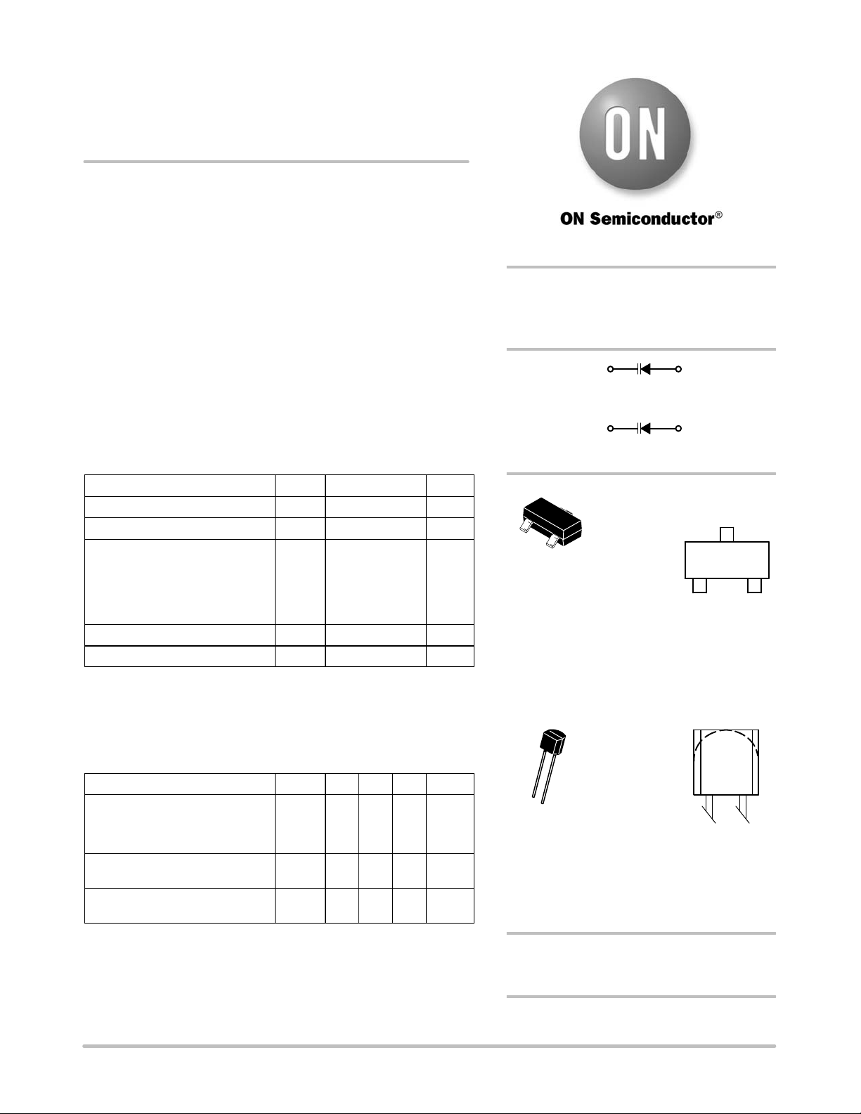
Silicon Tuning Diodes
These devices are designed in popular plastic packages for the high
volume requirements of FM Radio and TV tuning and AFC, general
frequency control and tuning applications. They provide solid−state
reliability in replacement of mechanical tuning methods. Also
available in a Surface Mount Package up to 33 pF.
Features
• High Q
• Controlled and Uniform Tuning Ratio
• Standard Capacitance Tolerance − 10%
• Complete Typical Design Curves
• Pb−Free Packages are Available
MAXIMUM RATINGS
Rating Symbol Value Unit
Reverse Voltage V
Forward Current I
Forward Power Dissipation
@ TA = 25°C MMBV21xx
Derate above 25°C
@ TA = 25°C MV21xx
Derate above 25°C LV2209
Junction Temperature T
Storage Temperature Range T
Maximum ratings are those values beyond which device damage can occur.
Maximum ratings applied to the device are individual stress limit values (not
normal operating conditions) and are not valid simultaneously. If these limits are
exceeded, device functional operation is not implied, damage may occur and
reliability may be affected.
ELECTRICAL CHARACTERISTICS (T
Characteristic Symbol Min Typ Max Unit
Reverse Breakdown Voltage
(IR = 10 mAdc)
MMBV21xx, MV21xx
LV2209
Reverse Voltage Leakage Current
(VR = 25 Vdc, TA = 25°C)
Diode Capacitance Temperature Coefficient (VR = 4.0 Vdc, f = 1.0 MHz)
R
F
P
D
J
stg
= 25°C unless otherwise noted)
A
V
(BR)R
I
R
TC
C
30 Vdc
200 mAdc
225
1.8
280
2.8
+150 °C
−55 to +150 °C
3025−−−
− − 0.1
− 280 − ppm/°C
mW
mW/°C
mW
mW/°C
Vdc
−
mAdc
http://onsemi.com
6.8−100 pF, 30 VOLTS
VOLTAGE VARIABLE
CAPACITANCE DIODES
3
Cathode
Cathode
3
1
2
SOT−23 (TO−236)
xxx = Specific Device Code
M = Date Code*
G = Pb−Free Package
(Note: Microdot may be in either location)
*Date Code orientation and/or overbar may
vary depending upon manufacturing location.
TO−92 (TO−226AC)
1
2
yyyyyy = Specific Device Code
A = Assembly Location
Y = Year
WW = Work Week
G = Pb−Free Package
(Note: Microdot may be in either location)
SOT−23
2
TO−92
CASE 318−08
STYLE 8
CASE 182
STYLE 1
1
Anode
1
Anode
MARKING
DIAGRAMS
xxx M G
1
yy
yyyy
AYWW G
G
G
© Semiconductor Components Industries, LLC, 2006
January, 2006 − Rev. 4
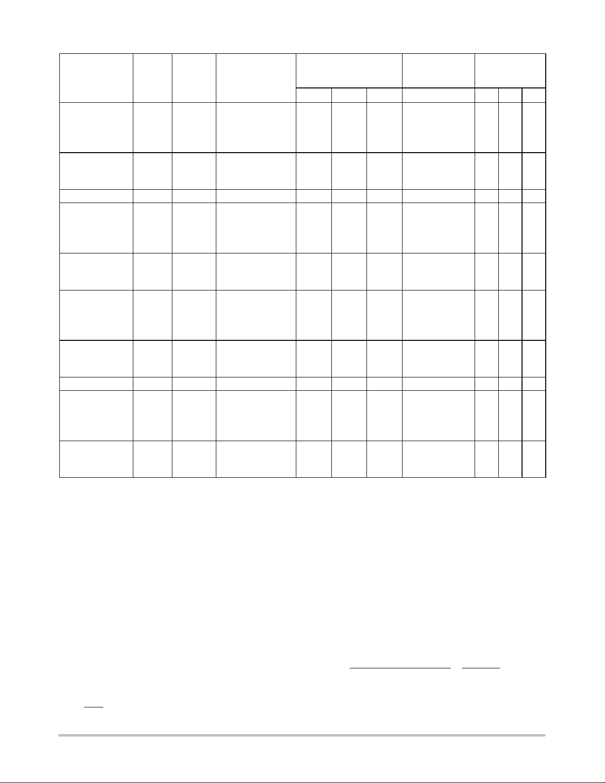
See detailed ordering and shipping information in the package
ORDERING INFORMATION
dimensions section on page 2 of this data sheet.
Preferred devices are recommended choices for future use
and best overall value.
1 Publication Order Number:
MMBV2101LT1/D
MMBV2101LT1 Series, MV2105, MV2101, MV2109, LV2209
CT, Diode Capacitance
VR = 4.0 Vdc, f = 1.0 MHz
Device Marking Package Shipping
MMBV2101LT1 M4G SOT−23 3,000 / Tape & Reel 6.1 6.8 7.5 450 2.5 2.7 3.2
MMBV2101LT1G M4G SOT−23
(Pb−Free)
MMBV2101L M4G SOT−23 Bulk (Note 1) 6.1 6.8 7.5 450 2.5 2.7 3.2
MV2101 MV2101 TO−92 1,000 per Box 6.1 6.8 7.5 450 2.5 2.7 3.2
MV2101G MV2101 TO−92
(Pb−Free)
MMBV2103LT1 4H SOT−23 3,000 / Tape & Reel 9.0 10 11 400 2.5 2.9 3.2
MMBV2105LT1 4U SOT−23 3,000 / Tape & Reel 13.5 15 16.5 400 2.5 2.9 3.2
MMBV2105LT1G 4U SOT−23
(Pb−Free)
MMBV2105L 4U SOT−23 Bulk (Note 1) 13.5 15 16.5 400 2.5 2.9 3.2
MV2105 MV2105 TO−92 1,000 per Box 13.5 15 16.5 400 2.5 2.9 3.2
MV2105G MV2105 TO−92
(Pb−Free)
MMBV2107LT1 4W SOT−23 3,000 / Tape & Reel 19.8 22 24.2 350 2.5 2.9 3.2
MMBV2107LT1G 4W SOT−23
(Pb−Free)
MMBV2107L 4W SOT−23 Bulk (Note 1) 19.8 22 24.2 350 2.5 2.9 3.2
MMBV2108LT1 4X SOT−23 3,000 / Tape & Reel 24.3 27 29.7 300 2.5 3.0 3.2
MMBV2108LT1G 4X SOT−23
(Pb−Free)
LV2209 LV2209 TO−92 1,000 per Box 29.7 33 36.3 200 2.5 3.0 3.2
MMBV2109LT1 4J SOT−23 3,000 / Tape & Reel 29.7 33 36.3 200 2.5 3.0 3.2
MMBV2109LT1G 4J SOT−23
(Pb−Free)
MMBV2109L 4J SOT−23 Bulk (Note 1) 29.7 33 36.3 200 2.5 3.0 3.2
MV2109 MV2109 TO−92 1,000 per Box 29.7 33 36.3 200 2.5 3.0 3.2
MV2109G MV2109 TO−92
(Pb−Free)
†For information on tape and reel specifications, including part orientation and tape sizes, please refer to our Tape and Reel Packaging
Specification Brochure, BRD8011/D.
1. MMBV2101LT1, MMBV2105LT1, MMBV2107LT1 thru MMBV2109LT1, are also available in bulk. Use the device title and drop the “T1”
suffix when ordering any of these devices in bulk.
3,000 / Tape & Reel 6.1 6.8 7.5 450 2.5 2.7 3.2
1,000 per Box 6.1 6.8 7.5 450 2.5 2.7 3.2
3,000 / Tape & Reel 13.5 15 16.5 400 2.5 2.9 3.2
1,000 per Box 13.5 15 16.5 400 2.5 2.9 3.2
3,000 / Tape & Reel 19.8 22 24.2 350 2.5 2.9 3.2
3,000 / Tape & Reel 24.3 27 29.7 300 2.5 3.0 3.2
3,000 / Tape & Reel 29.7 33 36.3 200 2.5 3.0 3.2
1,000 per Box 29.7 33 36.3 200 2.5 3.0 3.2
†
Min Nom Max Typ Min Typ Max
pF
Q, Figure of Merit
VR = 4.0 Vdc,
f = 50 MHz
TR, Tuning Ratio
C2/C
30
f = 1.0 MHz
PARAMETER TEST METHODS
1. CT, DIODE CAPACITANCE
(CT = CC + CJ). CT i s m easured a t 1 .0 M Hz u s ing a c apacitance
bridge (Boonton Electronics Model 75A or equivalent).
2. TR, TUNING RATIO
TR is the ratio of CT measured at 2.0 Vdc divided by C
measured at 30 Vdc.
3. Q, FIGURE OF MERIT
Q is c alculated b y t aking t he G a nd C readings of an a dmittance
bridge at the specified frequency and substituting in the
following equations:
2pfC
Q +
G
http://onsemi.com
(Boonton Electronics Model 33AS8 or equivalent). Use Lead
Length [ 1/16″.
4. TCC, DIODE CAPACITANCE TEMPERATURE
COEFFICIENT
TCC is guaranteed by comparing CT at VR = 4.0 Vdc, f = 1.0
T
MHz, TA = −65°C with CT at VR = 4.0 Vdc, f = 1.0 MHz, T
= +85°C in the following equation, which defines TCC:
TC
CT() 85°C) – CT(–65°C)
Ť
+
C
85 ) 65
Ť
·
CT(25°C)
10
Accuracy limited by measurement of CT to ±0.1 pF.
2
A
6

MMBV2101LT1 Series, MV2105, MV2101, MV2109, LV2209
TYPICAL DEVICE CHARACTERISTICS
1000
500
200
MMBV2109LT1/MV2109
100
50
MMBV2105LT1/MV2105
20
MMBV2101LT1/MV2101
10
, DIODE CAPACITANCE (pF)
5.0
T
C
2.0
1.0
0.1
0.5
Figure 1. Diode Capacitance versus Reverse Voltage
1.040
1.030
1.020
1.010
1.000
0.990
0.980
NORMALIZED DIODE CAPACITANCE
0.970
0.960
NORMALIZED TO C
TJ, JUNCTION TEMPERATURE (°C)
VR = 2.0 Vdc
VR = 30 Vdc
at TA = 25°C
VR = (CURVE)
Figure 2. Normalized Diode Capacitance versus
Junction Temperature
TA = 25°C
f = 1.0 MHz
1.0 2.00.2 10
VR, REVERSE VOLTAGE (VOLTS)
VR = 4.0 Vdc
0.50
0.20
T
+100
, REVERSE CURRENT (nA)
0.10
R
I
0.05
0.02
+125−75 −25 0 +25 +50−50 +75
0.01
3.00.3
100
50
20
10
5.0
2.0
1.0
0
5.0
5.0 10 2015 25
VR, REVERSE VOLTAGE (VOLTS)
Figure 3. Reverse Current versus Reverse Bias
3020
TA = 125°C
TA = 75°C
TA = 25°C
30
Voltage
5000
3000
2000
1000
500
300
200
100
Q, FIGURE OF MERIT
50
30
20
10
1.0 2.0 5.0 7.0
MMBV2109LT1
3.0
VR, REVERSE VOLTAGE (VOLTS)
MMBV2101LT1/MV2101
10
Figure 4. Figure of Merit versus Reverse Voltage
TA = 25°C
f = 50 MHz
20
30
http://onsemi.com
3
5000
3000
2000
1000
500
300
200
100
Q, FIGURE OF MERIT
50
30
TA = 25°C
20
VR = 4.0 Vdc
10
10
Figure 5. Figure of Merit versus Frequency
MMBV2101LT1/MV2101
MMBV2109LT1/MV2109
30 50 70
20 200 250
f, FREQUENCY (MHz)
100

MMBV2101LT1 Series, MV2105, MV2101, MV2109, LV2209
PACKAGE DIMENSIONS
SOT−23 (TO−236)
CASE 318−08
ISSUE AN
D
H
SEE VIEW C
E
c
0.25
3
E
12
b
e
q
A
L
A1
L1
VIEW C
NOTES:
1. DIMENSIONING AND TOLERANCING PER ANSI
Y14.5M, 1982.
2. CONTROLLING DIMENSION: INCH.
3. MAXIMUM LEAD THICKNESS INCLUDES LEAD
FINISH THICKNESS. MINIMUM LEAD
THICKNESS IS THE MINIMUM THICKNESS OF
BASE MATERIAL.
4. 318−01 THRU −07 AND −09 OBSOLETE, NEW
STANDARD 318−08.
DIMAMIN NOM MAX MIN
A1 0.01 0.06 0.10 0.001
b 0.37 0.44 0.50 0.015
c 0.09 0.13 0.18 0.003
D 2.80 2.90 3.04 0.110
E 1.20 1.30 1.40 0.047
e 1.78 1.90 2.04 0.070
L 0.10 0.20 0.30 0.004
L1
H
STYLE 8:
PIN 1. ANODE
MILLIMETERS
0.89 1.00 1.11 0.035
0.35 0.54 0.69 0.014 0.021 0.029
2.10 2.40 2.64 0.083 0.094 0.104
E
2. NO CONNECTION
3. CATHODE
INCHES
NOM MAX
0.040 0.044
0.002 0.004
0.018 0.020
0.005 0.007
0.114 0.120
0.051 0.055
0.075 0.081
0.008 0.012
SOLDERING FOOTPRINT*
0.95
0.95
0.037
0.037
2.0
0.079
0.9
0.035
SCALE 10:1
0.8
ǒ
inches
mm
Ǔ
0.031
*For additional information on our Pb−Free strategy and soldering
details, please download the ON Semiconductor Soldering and
Mounting Techniques Reference Manual, SOLDERRM/D.
http://onsemi.com
4

MMBV2101LT1 Series, MV2105, MV2101, MV2109, LV2209
PACKAGE DIMENSIONS
TO−92 (TO−226AC)
CASE 182−06
ISSUE L
SEATING
PLANE
A
B
R
D
P
XX
L
K
J
SECTION X−X
D
G
H
12
V
N
C
NOTES:
1. DIMENSIONING AND TOLERANCING PER ANSI
Y14.5M, 1982.
2. CONTROLLING DIMENSION: INCH.
3. CONTOUR OF PACKAGE BEYOND ZONE R IS
UNCONTROLLED.
4. LEAD DIMENSION IS UNCONTROLLED IN P AND
BEYOND DIMENSION K MINIMUM.
DIM MIN MAX MIN MAX
A 0.175 0.205 4.45 5.21
B 0.170 0.210 4.32 5.33
C 0.125 0.165 3.18 4.19
D 0.016 0.021 0.407 0.533
G 0.050 BSC 1.27 BSC
H 0.100 BSC 2.54 BSC
J 0.014 0.016 0.36 0.41
K 0.500 −−− 12.70 −−−
L 0.250 −−− 6.35 −−−
N 0.080 0.105 2.03 2.66
P −−− 0.050 −−− 1.27
R 0.115 −−− 2.93 −−−
V 0.135 −−− 3.43 −−−
STYLE 1:
PIN 1. ANODE
2. CATHODE
MILLIMETERSINCHES
N
ON Semiconductor and are registered trademarks of Semiconductor Components Industries, LLC (SCILLC). SCILLC reserves the right to make changes without further notice
to any products herein. SCILLC makes no warranty, representation or guarantee regarding the suitability of its products for any particular purpose, nor does SCILLC assume any liability
arising out of the application or use of any product or circuit, and specifically disclaims any and all liability, including without limitation special, consequential or incidental damages.
“Typical” parameters which may be provided in SCILLC data sheets and/or specifications can and do vary in different applications and actual performance may vary over time. All
operating parameters, including “Typicals” must be validated for each customer application by customer’s technical experts. SCILLC does not convey any license under its patent rights
nor the rights of others. SCILLC products are not designed, intended, or authorized for use as components in systems intended for surgical implant into the body, or other applications
intended to support or sustain life, or for any other application in which the failure of the SCILLC product could create a situation where personal injury or death may occur. Should
Buyer purchase or use SCILLC products for any such unintended or unauthorized application, Buyer shall indemnify and hold SCILLC and its officers, employees, subsidiaries, affiliates,
and distributors harmless against all claims, costs, damages, and expenses, and reasonable attorney fees arising out of, directly or indirectly, any claim of personal injury or death
associated with such unintended or unauthorized use, even if such claim alleges that SCILLC was negligent regarding the design or manufacture of the part. SCILLC is an Equal
Opportunity/Affirmative Action Employer. This literature is subject to all applicable copyright laws and is not for resale in any manner.
PUBLICATION ORDERING INFORMATION
LITERATURE FULFILLMENT:
Literature Distribution Center for ON Semiconductor
P.O. Box 61312, Phoenix, Arizona 85082−1312 USA
Phone: 480−829−7710 or 800−344−3860 Toll Free USA/Canada
Fax: 480−829−7709 or 800−344−3867 Toll Free USA/Canada
Email: orderlit@onsemi.com
N. American Technical Support: 800−282−9855 Toll Free
USA/Canada
Japan: ON Semiconductor, Japan Customer Focus Center
2−9−1 Kamimeguro, Meguro−ku, Tokyo, Japan 153−0051
Phone: 81−3−5773−3850
http://onsemi.com
ON Semiconductor Website: http://onsemi.com
Order Literature: http://www.onsemi.com/litorder
For additional information, please contact your
local Sales Representative.
MMBV2101LT1/D
5
 Loading...