

ON Semiconductor EZAIRO 7111 HYBRID Product information
Audio Processor for Digital
Hearing Aids
EZAIRO 7111 HYBRID
Introduction
Ezairo 7111 is an open−programmable DSP−based hybrid
specifically designed for use in high−performance hearing aid and
hearing implant devices. The Ezairo 7111 hybrid includes the
Ezairo 7100 System−on−Chip (SoC), with its high−precision
quad−core architecture that delivers 375 MIPS, without sacrificing
power consumption.
The highly integrated Ezairo 7100 includes an optimized,
dual−Harvard CFX Digital Signal Processor (DSP) core and HEAR
Configurable Accelerator signal processing engine. It also features an
Arm
Cortex−M3 Processor Subsystem that supports various types
of protocols for wireless communication. This block combines an
open−programmable controller with hardware accelerators for audio
coding and error correction support.
Ezairo 7100 also includes a programmable Filter Engine that
enables time domain filtering and supports an ultra−low−delay audio
path. When combined with non−volatile memory and wireless
transceivers, Ezairo 7100 forms a complete hardware platform.
The Ezairo 7111 hybrid contains the Ezairo 7100 SoC, 2 Mb
EEPROM storage and the necessary passive components to directly
interface with the transducers required in a hearing aid.
www.onsemi.com
SIP19
CASE 127ES
MARKING DIAGRAM
E7111−0
ZZZZZZ
(Top View)
E7111−0 = Specific Device Code
ZZZZZZ = Assembly Lot
Development Tools
Ezairo Preconfigured Suite (Pre Suite)*
The Ezairo Pre Suite provides a complete framework to easily
develop Ezairo−based hearing aids and fitting software. Included in
the Ezairo Pre Suite is a firmware bundle, configuration software, and
a cross−platform Software Development Kit (SDK) to develop your
own fitting software.
Open−Programmable Evaluation and Development Kit (EDK)
To develop your own firmware on Ezairo 7111, the Ezairo 7100
Evaluation and Development Kit (EDK) includes optimized hardware,
programming interface, and a comprehensive Integrated Development
Environment (IDE).
Note: This datasheet describes all features of the Ezairo 7111 hybrid
module. Not all of these features are available using the Ezairo
Preconfigured Suite.
ORDERING INFORMATION
Device Package
E7111−0-102A19-AG SIP19
(RoHS
Compliant)
†For information on tape and reel specifications, in-
cluding part orientation and tape sizes, please refer
to our Tape and Reel Packaging Specifications Brochure, BRD8011/D.
Shipping
250 / Tape &
†
Reel
Semiconductor Components Industries, LLC, 2017
March, 2021 − Rev. 3
1 Publication Order Number:
E7111/D

EZAIRO 7111 HYBRID
KEY FEATURES
• Programmable Flexibility: the open−programmable
DSP−based system can be customized to the specific
signal processing needs of manufacturers. Algorithms
and features can be modified or completely new
concepts implemented without having to modify the
chip.
• Fully Integrated Hybrid: includes the Ezairo 100
SoC, 2 Mbit EEPROM storage and the necessary
passive components to directly interface with the
transducers required in a hearing aid.
• Quad−core Architecture: includes a CFX DSP, a
HEAR Configurable Accelerator, an Arm Cortex−M3
Processor Subsystem and a programmable Filter
Engine. The system also includes an efficient
input/output controller (IOC), system memories, input
and output stages along with a full complement of
peripherals and interfaces.
• CFX DSP: a highly cycle−efficient, programmable core
that uses a 24−bit fixed−point, dual−MAC,
dual−Harvard architecture.
• HEAR Configurable Accelerator: a highly optimized
signal processing engine designed to perform common
signal processing operations and complex standard
filterbanks.
• Arm Cortex−M3 Processor Subsystem: a complete
subsystem that supports efficient data transfer to and
from a wireless transceiver. The subsystem includes
hardwired CODECS (G.722, CVSD) and Error
Correction support (Reed−Solomon, Hamming), as well
as a fully programmable Arm Cortex−M3 processor and
dedicated interfaces. It is compatible with various
wireless technologies (NFMI, RF).
• Programmable Filter Engine: a filtering system that
allows applying a various range of pre− or
post−processing filtering, such as IIR, FIR and biquad
filters.
• Configurable System Clock Speeds: 1.28 MHz,
1.92 MHz, 2.56 MHz, 3.84 MHz, 5.12 MHz, 6.4 MHz,
7.68 MHz, 8.96 MHz, 9.60 MHz, 10.24 MHz* (default
clock calibration), 12.80 MHz and 15.36 MHz to
optimize the computing performance versus power
consumption ratio. The calibration for these 12 clock
speeds are stored in the manufacturing area of the
EEPROM.
• Ultra−low Delay: programmable Filter Engine
supports an ultra−low−delay audio path of 0.044 ms
(44 ms) for superior performance of features such as
occlusion management.
• Ultra−high Fidelity: 85 dB system dynamic range with
up to 110 dB input signal dynamic range,
exceptionally−low system noise and low group delay.
• Ultra−low Power Consumption: <0.7 mA @
10.24 MHz system clock (executing a tight MAC−loop
in the CFX DSP core plus a typical hearing aid
filterbank on the HEAR Configurable Accelerator).
• High Output Level: output levels of ~139 dB SPL
possible with low impedance receiver (measured using
IEC 711 coupler).
• Diverse Memory Architecture: a total of 40 kwords of
program memory and 44 kwords of data memory,
shared between the four cores included on the
Ezairo 7100 chip.
• Data Security: sensitive program data can be encrypted
for storage in EEPROM to prevent unauthorized parties
from gaining access to proprietary algorithm
intellectual property.
• Signal Detection Unit: ultra−low−power detection
system for signals on any analog inputs.
• High Throughput Communication Interface: fast
2
C−based interface for quick download, debugging and
I
general communication.
• Highly Configurable Interfaces: two PCM interfaces,
2
C interfaces, two SPI interfaces, a UART
two I
interface as well as multiple GPIOs can be used to
stream configuration, control or signal data into and out
of the Ezairo 7111 hybrid.
• On−chip PLL: support for communication
synchronization with wireless transceiver.
• Glueless MMI: link to various analog and digital user
interfaces such as analog or digital volume control
potentiometers, push buttons for program selection and
microphone/telecoil switching.
• Fitting Support: support for Microcard, HI−PRO 2,
HI−PRO USB, QuickCom, and NOAHlink, including
NOAHlink’s audio streaming feature.
• These Devices are Pb−Free, Halogen Free/BFR Free
and are RoHS Compliant
www.onsemi.com
2
EZAIRO 7111 HYBRID
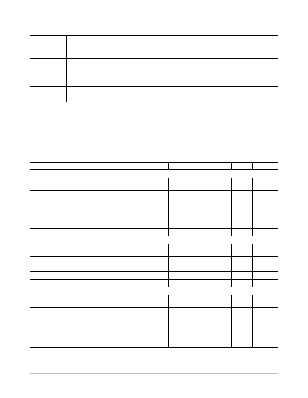
Table 1. ABSOLUTE MAXIMUM RATINGS
Symbol Parameter Min Max Unit
VBAT Power supply voltage 2 V
VBATOD Output drivers power supply voltage 2 V
Vin Voltage at any input pin GNDC−0.3 VDDO +
0.3
GNDC, GNDA Digital and Analog Grounds 0 − V
T functional Functional temperature range (Note 1) −40 85 °C
T operational Operational temperature range (Note 1) 0 50 °C
T storage Storage temperature range −40 85 °C
Caution: Class 2 ESD Sensitivity, JESD22−A114−B (2000 V)
Stresses exceeding those listed in the Maximum Ratings table may damage the device. If any of these limits are exceeded, device functionality
should not be assumed, damage may occur and reliability may be affected.
1. Electrical Specification may exceed listed tolerances when out of the temperature range 0°C to 50°C.
Electrical Performance Specifications
The tests were performed at 20°C with a 1.25 V supply voltage and 4.7 W series resistor to simulate a nominal hearing aid
battery. The system clock (SYS_CLK) was set to 5.12 MHz and an audio input sampling frequency of 16 kHz was used.
Parameters marked as screened are tested on each chip.
Table 2. ELECTRICAL SPECIFICATIONS
Description Symbol Conditions Min Typ Max Unit Screened
OVERALL
Supply Voltage
VBAT Supply voltage measured
at the VBAT pin
Current consumption I
VBAT
Filterbank: 30% load CFX:
100% load SYS_CLK:
10.24 MHz
Ezairo Pre Suite firmware
bundle running at 10.24
MHz, all algorithms active,
no transducers connected.
Stand by current Istb Using ON’s macro 40 120
VREG
Regulated voltage
output
Regulator PSRR VREG
Load current I
Load regulation LOAD
Line regulation LINE
VREG Trimmed bandgap
= 100 mA
I
load
PSRR
LOAD
REG
REG
1 kHz, VBAT = 1.25 V 76 80 − dB
5 mA < I
I
load
< 2 mA
load
= 1 mA − 2 5 mV/V
VDDA
Output voltage
trimming range
Regulator PSRR VDDA
Load current I
Load regulation LOAD
Line regulation LINE
VDDA Control register
configured, typical values
PSRR
LOAD
REG
REG
1 kHz, VBAT = 1.25 V 40 50 − dB
VBAT = 1.2 V; 100 mA <
I
< 1 mA
load
1.2 V < VBAT < 1.86 V;
= 100 mA
I
load
1.05 1.25 2.0 V
− 700 −
− 1090 −
mA
mA
mA
0.96 0.97 0.98 V √
− − 2 mA
− 4 10 mV/mA
1.8 2.0 2.1 V √
− − 1 mA
− 4 10 mV/mA
− 6 20 mV/V
V
www.onsemi.com
3

EZAIRO 7111 HYBRID
Table 2. ELECTRICAL SPECIFICATIONS
Description ScreenedUnitMaxTy pMinConditionsSymbol
VDBL
Output voltage
trimming range
VDBL Control register
configured, typical values,
unloaded
Regulator PSRR VDBL
Load current I
LOAD
PSRR
1 kHz, VBAT = 1.25 V 30 40 − dB
ITRIM
(A_CP_VDBL_CTRL) =
0x7
Load regulation LOAD
Line regulation LINE
REG
REG
VBAT = 1.2 V; 100 mA <
I
< 3 mA
load
VBAT > 1.2 V; I
100 mA
load
=
VDDC
Digital supply output
voltage trimming
range
VDDC output level
adjustment
Regulator PSRR VDDC
Load current I
Load regulation LOAD
Line regulation LINE
VDDC Control register
configured, typical values,
unloaded
VDDC
STEP
PSRR
LOAD
REG
REG
1 kHz, VBAT = 1.25 V 25 30 − dB
Delivered by LDO − − 5 mA
2. Recommended VDDC values depend on the system clock (SYS_CLK) frequency. Table 3 gives the recommended VDDC values for
different system clocks.
VDDM
Memory supply
output voltage
trimming range
VDDM output level
adjustment
Regulator PSRR VDDM
Load current I
Load regulation LOAD
Line regulation LINE
VDDM Control register
configured, typical values,
unloaded
VDDM
STEP
PSRR
LOAD
REG
REG
1 kHz, VBAT = 1.25 V 25 30 − dB
Delivered by LDO − − 5 mA
3. The minimum VDDM value required for proper system functioning is 0.90 V.
POWER−ON−RESET
POR startup voltage
POR shutdown
voltage
VBAT
VBAT
STARTUP
SHUTDOWN
4. Pass fail test with 0.855 V and 0.945 V
5. Pass fail test with 0.835 V and 0.925 V
INPUT STAGE
Analog input voltage
range
V
IN
Preamplifier gain PAG 3 dB steps 0 − 36 dB √
Preamplifier gain
accuracy
Input impedance R
PAG acc 1 kHz, PAG from 0 to
36 dB
IN
Non−0 dB preamplifier
gains
1.6 2.0 2.2 V √
− − 15 mA
− 4 10 mV/mA
− 6 20 mV/V
0.72 −
1.32 V √
(Note 2)
1.5 2.5 3 mV √
− 5 10 mV/mA
− 6 12 mV/V
0.82 −
1.32 V √
(Note 3)
1.5 2.5 3 mV √
− 5 10 mV/mA
− 6 12 mV/V
− 0.9 − V √ (Note 4)
− 0.88 − V √ (Note 5)
0 − 2 V
−1.5 0 1.5 dB √
370 500 725
kW
√
www.onsemi.com
4
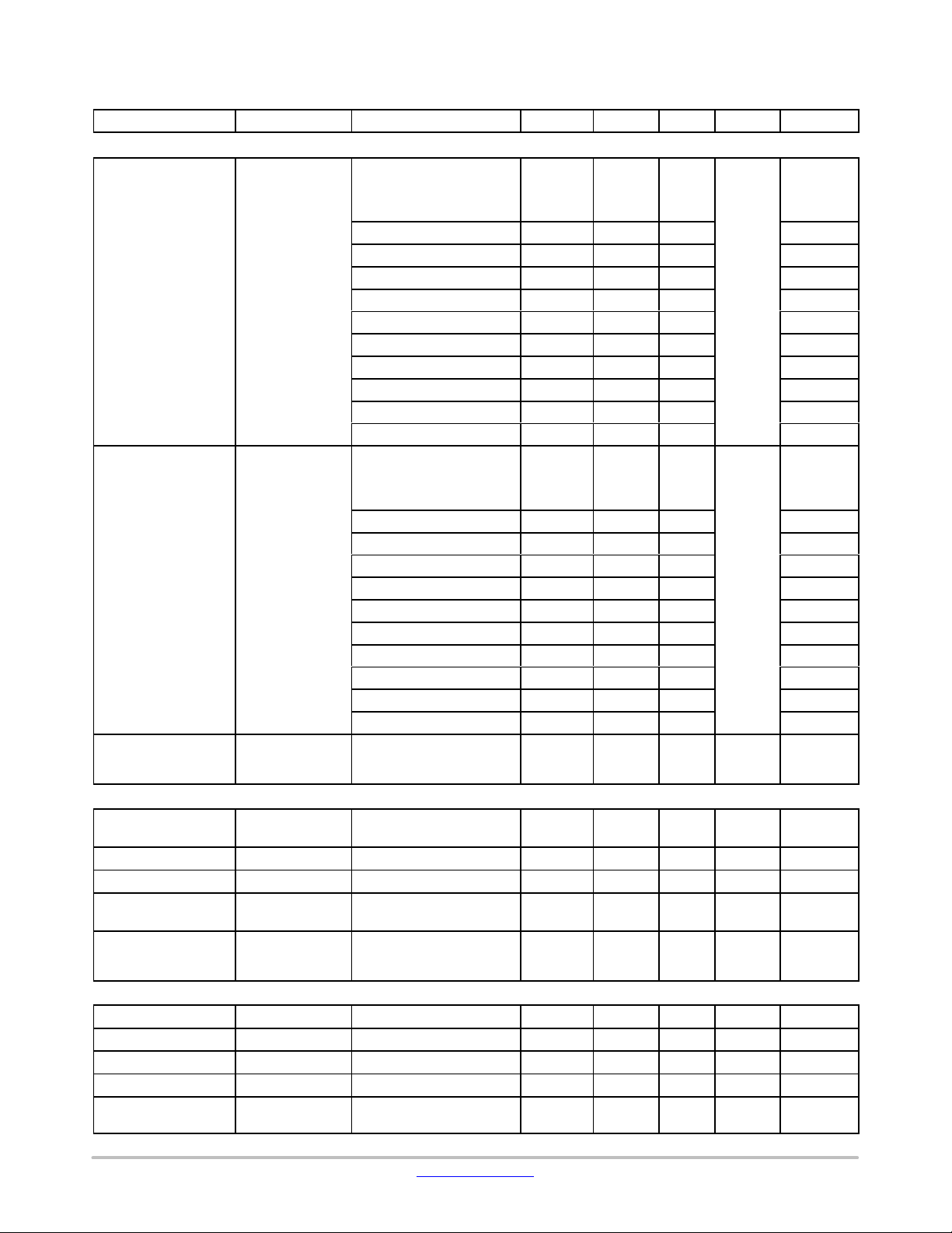
Table 2. ELECTRICAL SPECIFICATIONS
Description ScreenedUnitMaxTy pMinConditionsSymbol
INPUT STAGE
Input referred noise
Input Dynamic Range IN
Input peak THD+N IN
OUTPUT DRIVER
Maximum peak
current
Output impedance R
Output impedance R
Output dynamic
range
Output THD+N DO
10−BIT LOW−SPEED A/D
Input voltage range
INL LSAD
DNL LSAD
Sampling frequency LSAD
Channel sampling
frequency
IN
DO
LSAD
LSAD
IRN
DR
THD+N
I
DO
DO
DO
DR
THDN
RANGE
INL
DNL
SF
CH_SF
EZAIRO 7111 HYBRID
AIR connected to AGND
Unweighted, 100 Hz to
10 kHz BW
Preamplifier settings:
0 dB 53 −
12 dB 13 −
15 dB 9 −
18 dB 6.6 10.6 √
21 dB 4.9 −
24 dB 4.3 −
27 dB 3.7 −
30 dB 3.2 −
33 dB 3.2 −
36 dB 3.2 −
AIR connected to AGND
Unweighted, 100 Hz to
10 kHz BW
Preamplifier settings:
0 dB −
12 dB −
15 dB −
18 dB 81
21 dB −
24 dB −
27 dB −
30 dB −
86
86
86
86
85
82
82
80
33 dB − 77
36 dB − 74
Any preamplifier gain
−10 dBFS signal at
− − −68 dB √
preamp output, 1kHz.
High Power mode − − 25 mA
Normal mode, I
= 1 mA − 4.5 5.5
load
High Power mode − 2.5 4
Normal mode,
90 − − dB
VBAT = 1.25 V
At 1 kHz, −6 dBFS, 8 kHz
− −78 −76 dB
bandwidth, VBAT = 1.25 V,
normal mode
Peak input voltage 0 − 1.94 V √
From GND to 2*VREG −4 − +4 LSB
From GND to 2*VREG −2 − +2 LSB
All channels sequentially − 12.8 − kHz
− 1.6 − kHz
mVrms
dB
W
W
√
www.onsemi.com
5
 Loading...