

Onkyo TX SR501 - AV Receiver - 5.1 Channel, TX SR501 Instruction Manual

En
AV Receiver
TX-SR501
TX-SR501E
Instruction Manual
Thank you for purchasing the Onkyo AV Receiver.
Please read this manual thoroughly before making connections and plugging in the unit.
Following the instructions in this manual will enable you
to obtain optimum performance and listening enjoyment
from your new AV Receiver.
Please retain this manual for future reference.
Contents
Introduction
Important Safeguards................................................2
Precautions................................................................3
Supplied Accessories................................................4
Features.....................................................................4
Before Using the TX-SR501/TX-SR501E ...............5
Controls & Connectors.............................................6
Connections
Connecting Your AV Components.........................10
Connecting -compatible AV Components........19
Installing Your Speakers ........................................20
Connecting Antenna ...............................................22
Setup
Powering Up & Setting Up the TX-SR501/
TX-SR501E.........................................................24
Important—First Time Setup..............................24
Configuring Speaker Set A.....................................26
Operation
Playing Your AV Components...............................28
Using the Tuner ......................................................30
Common Functions.................................................32
Using the Listening Modes.....................................34
Audio Adjust Functions..........................................37
Recording................................................................39
Remote Controller
Using the Remote Controller RC-479S with Your
Other AV Components........................................40
Using the Remote Controller RC-518M with Your
Other AV Components........................................41
Appendix
Troubleshooting......................................................45
Specifications..........................................................48
2
Important Safeguards
1. Read Instructions—All the safety and operating instructions
should be read before the appliance is operated.
2. Retain Instructions—The safety and operating instructions
should be retained for future reference.
3. Heed War nings—All warnings on the appliance and in the
operating instructions should be adhered to.
4. Follow Instructions—All operating and use instructions
should be followed.
5. Cleaning—Unplug the appliance from the wall outlet before
cleaning. The appliance should be cleaned only as recommended by the manufacturer.
6. Attachments—Do not use attachments not recommended by
the appliance manufacturer as they may cause hazards.
7. Water and Moisture—Do not use the appliance near water
–for example, near a bath tub, wash bowl, kitchen sink, or laundry tub; in a wet basement; or near a swimming pool; and the
like.
8. Accessories—Do not place the appli-
ance on an unstable cart, stand, tripod,
bracket, or table. The appliance may
fall, causing serious injury to a child or
adult, and serious damage to the appliance. Use only with a cart, stand, tripod, bracket, or table recommended by
the manufacturer, or sold with the
appliance. Any mounting of the appliance should follow the
manufacturer’s instructions, and should use a mounting accessory recommended by the manufacturer.
9. An appliance and cart combination should be moved with care.
Quick stops, excessive force, and une ven surfaces may cause the
appliance and cart combination to overturn.
10. Ventilation—Slots and openings in the cabinet are provided for
ventilation and to ensure reliable operation of the appliance and
to protect it from overheating, and these openings must not be
blocked or covered. The openings should never be blocked by
placing the appliance on a bed, sofa, rug, or other similar surface. The appliance should not be placed in a built-in installation
such as a bookcase or rack unless proper ventilation is provided.
There should be free space of at least 8 in. (20 cm) and an opening behind the appliance.
11. Power Sources—The appliance should be operated only from
the type of power source indicated on the marking label. If you
are not sure of the type of power supply to your home, consult
your appliance dealer or local power company.
12. Grounding or Polarization—The appliance may be equipped
with a polarized alternating current line plug (a plug having one
blade wider than the other). This plug will fit into the power
outlet only one way. This is a safety feature. If you are unable to
insert the plug fully into the outlet, try reversing the plug. If the
plug should still fail to fit, contact your electrician to replace
your obsolete outlet. Do not defeat the safety purpose of the
polarized plug.
13. Power Cord Protection—Power-supply cords should be
routed so that they are not likely to be walked on or pinched by
items placed upon or against them, paying particular attention
to cords at plugs, convenience receptacles, and the point where
they exit from the appliance.
14. Outdoor Antenna Grounding—If an outside antenna or cable
system is connected to the appliance, be sure the antenna or
cable system is grounded so as to provide some protection
against voltage surges and built-up static char ges. Article 810 of
the National Electrical Code, ANSI/NFPA 70, provides information with regard to proper grounding of the mast and supporting structure, grounding of the lead-in wire to an antennadischarge unit, size of grounding conductors, location of
antenna-discharge unit, connection to grounding electrodes, and
requirements for the grounding electrode. See Figure 1.
15. Lightning—For added protection for the appliance during a
lightning storm, or when it is left unattended and unused for
long periods of time, unplug it from the wall outlet and disconnect the antenna or cable system. This will prevent damage to
the appliance due to lightning and power-line surges.
16.Power Lines—An outside antenna system should not be
located in the vicinity of overhead power lines or other electric
light or power circuits, or where it can fall into such power lines
or circuits. When installing an outside antenna system, extreme
care should be taken to keep from touching such power lines or
circuits as contact with them might be fatal.
17. Overloading—Do not overload wall outlets, extension cords,
or integral convenience receptacles as this can result in a risk of
fire or electric shock.
18. Object and Liquid Entry—Never push objects of any kind
into the appliance through openings as they may touch dangerous voltage points or short-out parts that could result in a fire or
electric shock. Never spill liquid of any kind on the appliance.
19. Servicing—Do not attempt to service the appliance yourself as
opening or removing covers may expose you to dangerous v oltage or other hazards. Refer all servicing to qualified service personnel.
20. Damage Requiring Service—Unplug the appliance form the
wall outlet and refer servicing to qualified service personnel
under the following conditions:
A. When the power-supply cord or plug is damaged,
B. If liquid has been spilled, or objects have fallen into the appli-
ance,
C. If the appliance has been exposed to rain or water,
D. If the appliance does not operate normally by following the
operating instructions. Adjust only those controls that are cov-
ered by the operating instructions as an improper adjustment of
other controls may result in damage and will often require
extensive work by a qualified technician to restore the appliance
to its normal operation,
E. If the appliance has been dropped or damaged in any way, and
F. When the appliance exhibits a distinct change in performance –
this indicates a need for service.
WARNING:
TO REDUCE THE RISK OF FIRE OR ELECTRIC SHOCK,
DO NOT EXPOSE THIS APPLIANCE TO RAIN OR
MOISTURE.
CAUTION:
TO REDUCE THE RISK OF ELECTRIC SHOCK, DO NOT
REMOVE COVER (OR BACK). NO USER-SERVICEABLE
PARTS INSIDE. REFER SERVICING TO QUALIFIED
SERVICE PERSONNEL.
The lightning flash with arrowhead symbol, within an equilateral
triangle, is intended to alert the user to the presence of uninsulated
“dangerous voltage” within the product’s enclosure that may be of
sufficient magnitude to constitute a risk of electric shock to persons.
The exclamation point within an equilateral triangle is intended to
alert the user to the presence of important operating and maintenance
(servicing) instructions in the literature accompanying the appliance.
WARNING
RISK OF ELECTRIC SHOCK
DO NOT OPEN
RISQUE DE CHOC ELECTRIQUE
NE PAS
OUVRIR
AVIS
PORTABLE CART WARNING
S3125A
3
Important Safeguards—Continued
21. Replacement Parts—When replacement parts are required, be
sure the service technician has used replacement parts specified
by the manufacturer or have the same characteristics as the original part. Unauthorized substitutions may result in fire, electric
shock, or other hazards.
22. Safety Check—Upon completion of any service or repairs to
the appliance, ask the service technician to perform safety
checks to determine that the appliance is in proper operation
condition.
23. Wall or Ceiling Mounting —The appliance should be mounted
to a wall or ceiling only as recommended by the manufacturer.
24. Heat—The appliance should be situated away from heat
sources such as radiators, heat registers, stoves, or other appliances (including amplifiers) that produce heat.
25. Liquid Hazards—The appliance should not be exposed to
dripping or splashing and no objects filled with liquids, such as
vases should be placed on the appliance.
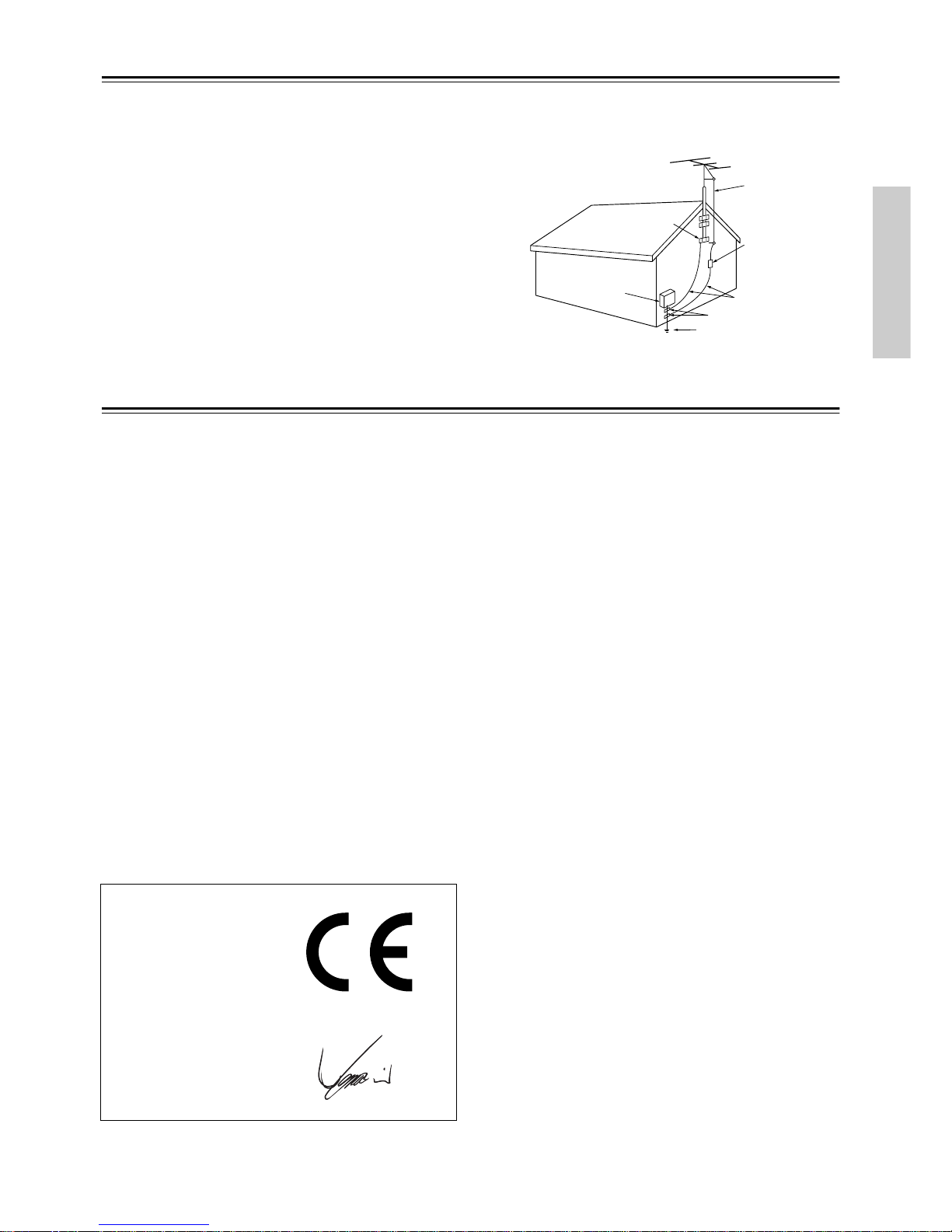
FIGURE 1:
EXAMPLE OF ANTENNA GROUNDING AS PER
NA TIONAL ELECTRICAL CODE, ANSI/NFPA 70
Precautions
For British models
Replacement and mounting of an A C plug on the power supply cord
of this unit should be performed only by qualified service personnel.
IMPORTANT
The wires in the mains lead are coloured in accordance with the
following code:
Blue: Neutral
Brown: Live
As the colours of the wires in the mains lead of this apparatus may
not correspond with the coloured markings identifying the terminals
in your plug, proceed as follows:
The wire which is coloured blue must be connected to the terminal
which is marked with the letter N or coloured black.
The wire which is coloured brown must be connected to the terminal
which is marked with the letter L or coloured red.
IMPORTANT
A 5 ampere fuse is fitted in this plug. Should the fuse need to be
replaced, please ensure that the replacement fuse has a rating of 5
amperes and that it is approved by ASTA or BSI to BS1362. Check
for the ASTA mark or the BSI mark on the body of the fuse.
IF THE FITTED MOULDED PLUG IS UNSUITABLE FOR THE
SOCKET OUTLET IN YOUR HOME THEN THE FUSE
SHOULD BE REMOVED AND THE PLUG CUT OFF AND DISPOSED OF SAFEL Y. THERE IS A DANGER OF SEVERE ELECTRICAL SHOCK IF THE CUT OFF PLUG IS INSERTED INTO
ANY 13 AMPERE SOCKET.
If in any doubt, consult a qualified electrician.
For European Models
For U.S. models
Note to CATV system installer:
This reminder is provided to call the CATV system installer's attention to Section 820-40 of the NEC which provides guidelines for
proper grounding and, in particular, specifies that the cable ground
shall be connected to the grounding system of the building, as close
to the point of cable entry as practical.
FCC Information for User
CAUTION:
The user changes or modifications not expressly approved by the
party responsible for compliance could void the user’s authority to
operate the equipment.
NOTE:
This equipment has been tested and found to comply with the limits
for a Class B digital device, pursuant to Part 15 of the FCC Rules.
These limits are designed to provide reasonable protection against
harmful interference in a residential installation.
This equipment generates, uses and can radiate radio frequency
energy and, if not installed and used in accordance with the instructions, may cause harmful interference to radio communications.
However, there is no guarantee that interference will not occur in a
particular installation. If this equipment does cause harmful interference to radio or television reception, which can be determined by
turning the equipment off and on, the user is encouraged to try to
correct the interference by one or more of the following measures:
• Reorient or relocate the receiving antenna.
• Increase the separation between the equipment and receiver.
• Connect the equipment into an outlet on a circuit different from
that to which the receiver is connected.
• Consult the dealer or an experienced radio/TV technician for help.
For Canadian Models
NOTE: THIS CLASS B DIGITAL APPARATUS COMPLIES
WITH CANADIAN ICES-003.
For models having a power cord with a polarized plug:
CAUTION: TO PREVENT ELECTRIC SHOCK, MATCH
WIDE BLADE OF PLUG TO WIDE SLOT, FULLY INSERT.
Modèle canadien
REMARQUE: CET APPAREIL NUMÉRIQUE DE LA
CLASSE B EST CONFORME À LA NORME NMB-003 DU
CANADA.
Sur les modèles dont la fiche est polarisée:
ATTENTION: POUR ÉVITER LES CHOCS ÉLECTRIQUES,
INTRODUIRE LA LAME LA PLUS LARGE DE LA FICHE
DANS LA BORNE CORRESPONDANTE DE LA PRISE ET
POUSSER JUSQU’AU FOND.
ANTENNA
DISCHARGE UNIT
(NEC SECTION 810-20)
GROUNDING CONDUCTORS
(NEC SECTION 810-21)
GROUND CLAMPS
POWER SERVICE GROUNDING
ELECTRODE SYSTEM
(NEC ART 250, PART H)
NEC – NATIONAL ELECTRICAL CODE
ELECTRIC
SERVICE
EQUIPMENT
GROUND
CLAMP
ANTENNA
LEAD IN
WIRE
S2898A
Declaration of Conformity
We,
ONKYO EUROPE
ELECTRONICS GmbH
LIEGNITZERSTRASSE
6, 82194 GROEBENZELL,
GERMANY
GROEBENZELL, GERMANY
ONKYO EUROPE ELECTRONICS GmbH
I. MORI
declare in own responsibility, that the ONKYO product described
in this instruction manual is in compliance with the corresponding
technical standards such as EN60065, EN55013, EN55020 and
EN61000-3-2, -3-3.
4
Precautions—Continued
1. Recording Copyright—Unless it’s for personal use only,
recording copyrighted material is illegal without the permission
of the copyright holder.
2. AC Fuse—The AC fuse inside the TX-SR501/TX-SR501E is
not user-serviceable. If you cannot turn on the TX-SR501/
TX-SR501E, contact your Onkyo dealer.
3. Care—Occasionally you should dust the TX-SR501/
TX-SR501E all over with a soft cloth. For stubborn stains, use
a soft cloth dampened with a weak solution of mild detergent
and water. Dry the TX-SR501/TX-SR501E immediately afterwards with a clean cloth. Don’t use abrasive cloths, thinners,
alcohol, or other chemical solvents, because they may damage
the finish or remove the panel lettering.
4. Power
WARNING
BEFORE PLUGGING IN THE UNIT FOR THE FIRST TIME,
READ THE FOLLOWING SECTION CAREFULLY.
AC outlet voltages vary from country to country. Mak e sure that the
voltage in your area meets the voltage requirements printed on the
TX-SR501/TX-SR501E’s rear panel (e.g., AC 230 V, 50 Hz or AC
120 V, 60 Hz).
The Worldwide model has a voltage selector for compatibility with
power systems around the world. Before you plug in this model,
make sure that the voltage selector is set to the correct voltage for
your area.
Setting the [STANDBY/ON] switch to STANDBY does not fully
shutdown the TX-SR501/TX-SR501E. If you do not intend to use
the TX-SR501/TX-SR501E for an extended period, remove the
power cord from the AC outlet.
Memory backup
The TX-SR501/TX-SR501E uses a battery-less memory backup
system in order to retain radio presets and other settings when it’s
unplugged or in the case of a power failure. Although no batteries
are required, the TX-SR501/TX-SR501E must be plugged into an
AC outlet in order to charge the backup system.
(On non-North American models, the TX-SR501/
TX-SR501E’s PO WER switch must be set to ON in order to
charge the backup system.) Once it has been charged, the
TX-SR501/TX-SR501E will retain the settings for several
weeks, although this depends on the environment and will be
shorter in humid climates.
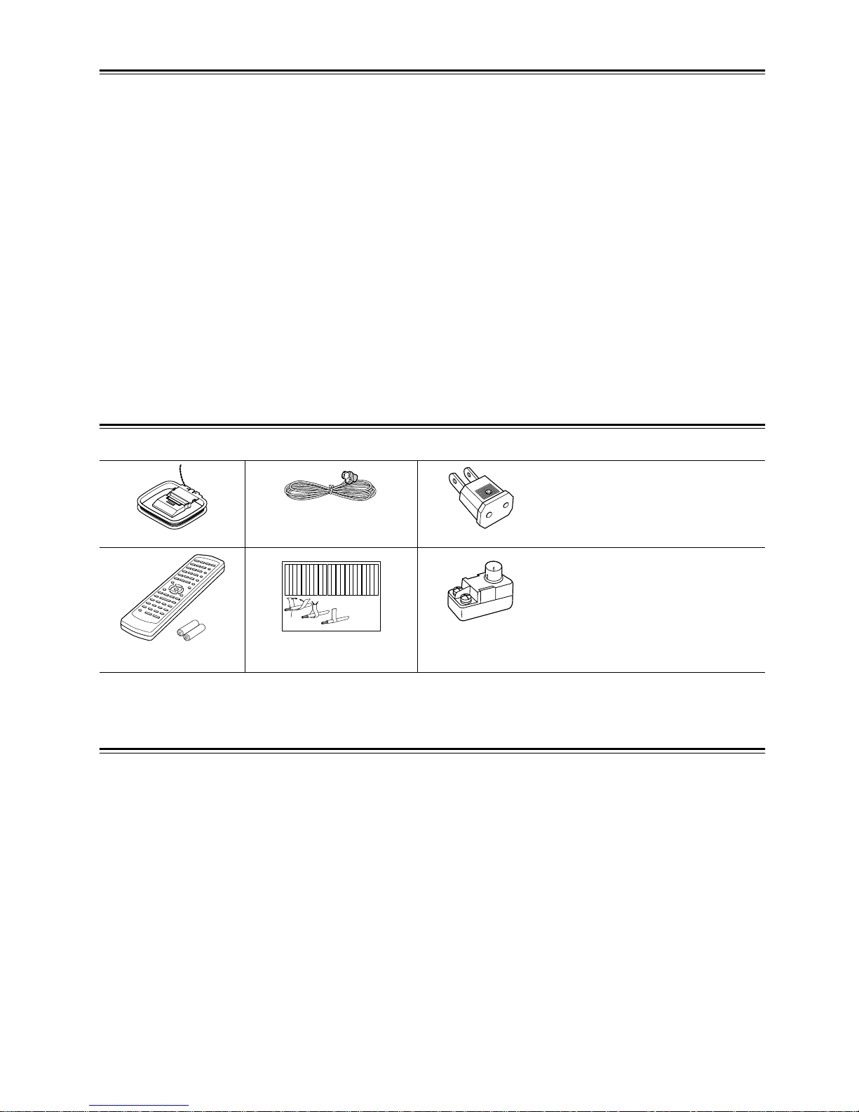
Supplied Accessories
Make sure you have the following accessories:
* In catalogs and on packaging, the letter added to the end of the product name indicates the color of the TX-SR501/TX-SR501E. Specifications and operation
are the same regardless of color.
Features
Amp
• 6-channel amplifier
• 65 watts per channel into 8 ohms, 20 Hz–20 kHz with less
than 0.08% total harmonic distortion
• WRAT (Wide Range Amplifier Technology)
• Optimum gain volume circuitry
Audio/Video
• Dolby
*1
Digital EX and Dolby Pro Logic II
• DTS, DTS-ES Matrix/Discrete 6.1, and DTS Neo:6 processing
*2
• Cinema Filter function
• Advanced 24-bit DSP chip (5 DSP soundfields)
• Linear PCM 96 kHz/24-bit D/A converters on all channels
• Adjustable crossover (60, 80, 100, 120, 150 Hz)
•2 component video inputs, 1 output
•4 S-Video inputs, 2 outputs
•3 assignable digital inputs (2 optical, 1 coaxial)
• Subwoofer pre out
• Color-coded multi-channel inputs
• Color-coded speaker terminal posts (SPEAKERS B use
push-type terminals)
FM/AM T uner
• 30 FM/AM presets
• FM auto tuning
• RDS (Radio Data System) (Europe only)
AM loop antenna
Indoor FM antenna
(connector type varies from
country to country)
Power-plug adapter
Only supplied in certain countries. Use
this adapter if your AC outlet does not
match with the plug on the TX-SR501/
TX-SR501E’s power cord. (Adapter varies from country to country.)
Remote controller &
two batteries (AA/R6)
Speaker cable labels
75/300-ohm antenna
adapter
Not supplied with North American and
European models.
Front
Left
Front
Left
SP-B
/
Zone 2
Left
SP-B
/
Zone 2
Left
Surround
Right
Surround
Right
Surround Back
Right
Surround Back
Right
Zone 2
Right
Zone 2
Right
Front
Left
Front
Left
SP-B
/
Zone 2
Left
SP-B
/
Zone 2
Left
Front
Right
Front
Right
SP-B
/
Zone 2
Right
SP-B
/
Zone 2
Right
Front
Right
Front
Right
SP-B
/
Zone 2
Right
SP-B
/
Zone 2
Right
Surround
Right
Surround
Right
Center
Center
Center
Center
Surround
Left
Surround
Left
Surround
Left
Surround
Left
Surround Back
Right
Surround Back
Right
Zone 2
Right
Zone 2
Right
Surround Back
Left
Surround Back
Left
Zone 2
Left
Zone 2
Left
Surround Back
Left
Surround Back
Left
Zone 2
Left
Zone 2
Left
1
2
3
Speaker Cable
*1. Manufactured under license from Dolby Laboratories. “Dolby,” “Pro Logic,” Surround EX, ” and the double-D symbol are trademarks of Dolby Laborato-
ries.
*2. “DTS,” “DTS-ES Extended Surround,” and “Neo:6” are trademarks of Digital Theater Systems, Inc.
5
Before Using the TX-SR501/TX-SR501E
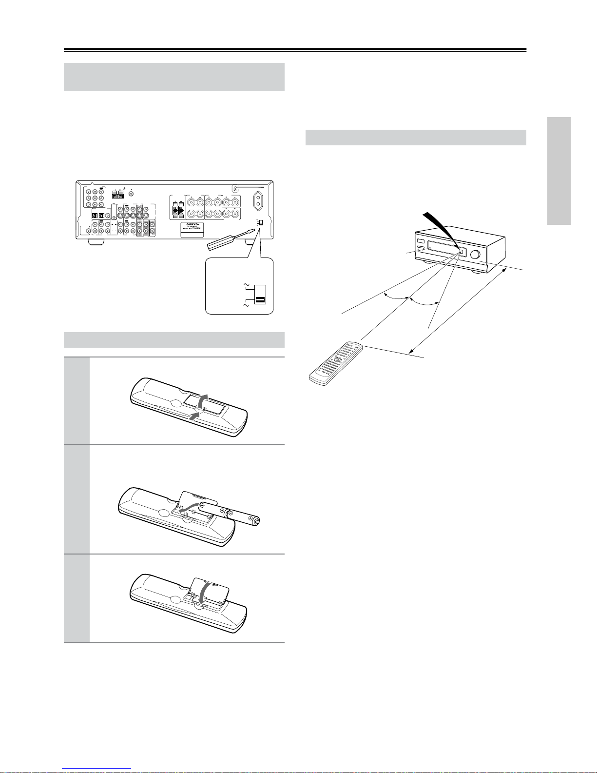
The Worldwide model has a voltage selector for compatibility with power systems around the world. Before you plug in
this model, make sure that the voltage selector is set to the
correct voltage for your area. If it isn’t, use a small screwdriver to set it as appropriate. For example, if the voltage in
your area is 120 volts (V), set the selector to “120V.” And if
it’s between 220 and 230 volts (V), set it to “220–230V.”
Notes:
• The supplied batteries should last for about six months,
although this will vary with usage.
• If the remote controller doesn’t work reliably , try replacing
both batteries.
• Don’t mix new and old batteries, or different types of batteries.
• If you intend not to use the remote controller for a long
time, remove the batteries to prevent possible leakage and
corrosion.
• Flat batteries should be removed as soon as possible to prevent possible leakage and corrosion.
To use the remote controller, point it at the TX-SR501/
TX-SR501E’s remote control sensor, as shown below. The
TX-SR501/TX-SR501E’s STANDBY indicator flashes
while a signal is being received from the remote controller.
Notes:
• The remote controller may not work reliably if the
TX-SR501/TX-SR501E is subjected to bright light, such
as direct sunlight or inverter-type fluorescent lights. Keep
this in mind when installing the TX-SR501/TX-SR501E.
• If another remote controller of the same type is used in the
same room, or the TX-SR501/TX-SR501E is installed
close to equipment that uses infrared rays, the remote controller may not work reliably.
• Don’t put anything, such as a book, on the remote controller, because the buttons may be pressed inadvertently,
thereby draining the batteries.
• The remote controller may not work reliably if the
TX-SR501/TX-SR501E is installed in a rack behind colored glass doors. Keep this in mind when installing the
TX-SR501/TX-SR501E.
• The remote controller will not work if there’s an obstacle
between it and the TX-SR501/TX-SR501E’s remote control sensor.
Setting the Voltage Selector
(Worldwide model only)
Installing the Batteries
1
Open the battery compartment, as shown.
2
Insert the two supplied batteries (AA/R6) in
accordance with the polarity diagram inside
the battery compartment.
3
Close the battery compartment.
L
R
RLR
L
ANTENNA
FM
75
AM
FRONT
SPEAKERS A
FRONT
SPEAKERS B
SURROUND
SPEAKERS
CENTER
SPEAKER
R
L
SURROUND BACK
SPEAKER
REMOTE
CONTROL
IN
IN
IN
OPTICAL COAXIAL
12
IN
IN
IN
IN
FRONT
SURR
CENTER
SUB
WOOFER
OUT
OUT
OUT
DIGITAL INPUT
VIDEO 2
VIDEO 1
DVD MONITOR
OUT
VIDEO
S VIDEO
DVD
TAPE
CD
L
R
VIDEO 2
VIDEO 1
SUBWOOFER
PRE OUT
VIDEO 1
/2/3
IN
DVD IN
COMPONENT VIDEO
Y
P
B
PR
OUT
L
R
SWITCHED
100W MAX.
AC OUTLET
120 V
VOLTAGE
SELECTOR
220-230 V
120 V
VOLTAGE
SELECTOR
220-230 V
Using the Remote Controller
30˚
30˚
TX-SR501/TX-SR501E
Remote control sensor
Standby indicator
Approx. 16 ft. (5 m)
6
Controls & Connectors
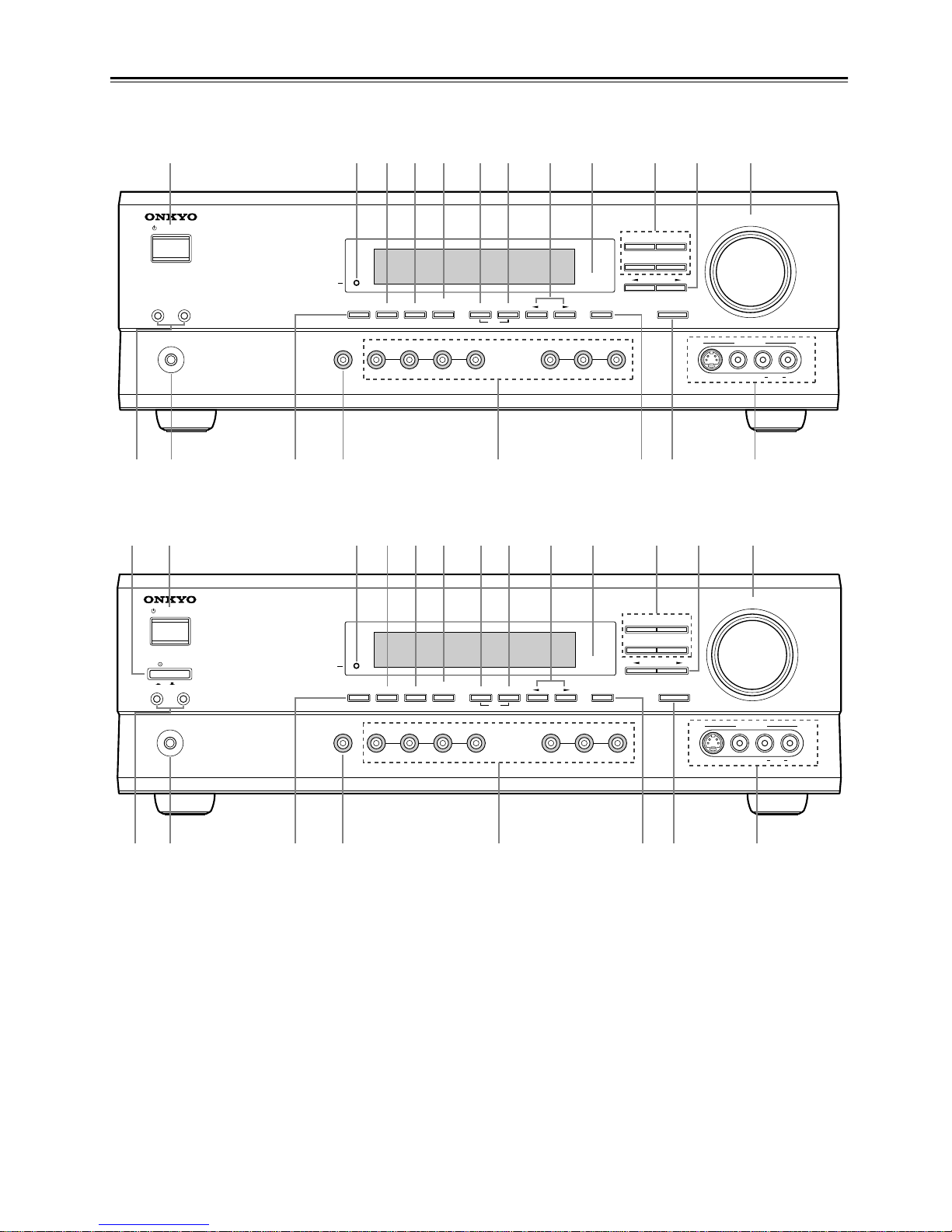
Front Panel
For detailed information, refer to the pages in parenthesis.
A POWER switch (24)
The North American model doesn’t have this switch.
This is the main power switch. When set to OFF, the
TX-SR501/TX-SR501E is completely shutdown. When set to
ON, the TX-SR501/TX-SR501E is in Standby mode and the
STANDBY indicator lights up.
Don’t turn on the power until you’ve completed, and double
checked all connections (pages 10–23).
Note:
Turning on the TX-SR501/TX-SR501E may cause a momentary power surge that might interfere with other electrical
equipment on the same circuit. If this is a problem, plug the
TX-SR501/TX-SR501E into a different branch circuit.
B STANDBY/ON button (24)
This button is used to set the TX-SR501/TX-SR501E to On or
Standby. For models with a POWER switch, this button has no
effect unless the POWER switch is set to ON.
C STANDBY indicator (24)
This indicator lights up when the TX-SR501/TX-SR501E is in
Standby mode, and it flashes while a signal is being received
from the remote controller.
D DIMMER button (32)
This button is used to adjust the display brightness.
E DIGITAL INPUT button (24)
This button is used to assign the digital inputs.
F SUBWOOFER MODE button (25)
This button is used to select the Subwoofer modes.
STANDBY/ON
PHONES
MASTER VOLUME
VIDEO
2
TAPE TUNER
C
D
VIDEO
3
DVD
AB
SPEAKERS
DIMMER
SURROUND
VIDEO 1
VCR
AUDIO
SELECTOR
DSP
STEREO
STANDBY
DISPLAY
AUDIO ADJUST
SPEAKER ADJUST
FM MODE
SUBWOOFER
MODE
DIGITAL INPUT
MEMORY
DIRECT
S VIDEO AUDIO
VIDEO L R
TUNING
CLEAR
PRESET/ADJUST
VIDEO 3
INPUT
OQR TUSP
234589JKML6N7
North American Model
STANDBY/ON
PHONES
MASTER VOLUME
VIDEO
2
TAPE TUNER
C
D
VIDEO
3
DVD
AB
SPEAKERS
DIMMER
SURROUND
VIDEO 1
VCR
AUDIO
SELECTOR
DSP
STEREO
STANDBY
DISPLAY
AUDIO ADJUST
SPEAKER ADJUST
FM MODE
SUBWOOFER
MODE
DIGITAL INPUT
MEMORY
DIRECT
S VIDEO AUDIO
VIDEO L R
TUNING
CLEAR
PRESET/ADJUST
VIDEO 3
INPUT
OQR TUSP
234589JKML6N7
OFFON
POWER
1
Other Models
7
Controls & Connectors—Continued
G MEMORY button (30, 31)
This button is used when storing and deleting radio presets.
H FM MODE button (31)
This button is used to select the FM radio Stereo and Mono
modes. It’s also used when deleting radio presets.
I TUNING [ ] [ ] buttons (30)
These buttons are used to tune into radio stations.
J Remote control sensor (5)
This sensor receives control signals from the remote controller.
K Listening mode buttons (36)
These buttons are used to select the listening modes.
L PRESET/ADJUST [ ] [ ] buttons (25, 26, 31,
37)
This button is used to select radio presets and adjust parameter
values.
M MASTER VOLUME control (28, 30)
This control is used to set the volume of the TX-SR501/
TX-SR501E.
N SPEAKER A & B buttons (28, 32)
These buttons are used to turn speaker sets A and B on and off.
O PHONES jack (33)
This 1/4-inch phone jack is for connecting a standard pair of
stereo headphones for private listening.
P DISPLAY button (32)
This button is used to display various information about the
currently selected source.
Q AUDIO SELECTOR button (28, 29)
This button is used to select the input signal format.
R Input selector buttons (24, 28–30, 39)
These buttons are used to select the audio and video sources:
CD, DVD, TAPE, TUNER, VIDEO 1, VIDEO 2, or VIDEO 3.
S SPEAKER ADJUST button (25, 26)
This button is used to adjust various speaker-related parameters.
T AUDIO ADJUST button (37)
This button is used to set the Bass, Treble, Late Night, Cinema
Filter, Center Image, Panorama, Dimension, and Center Width
functions.
U VIDEO 3 INPUT connectors (15, 39)
These S-Video, composite video (RCA/phono), and analog
audio (RCA/phono) inputs can be used to connect a video
camera or games console.
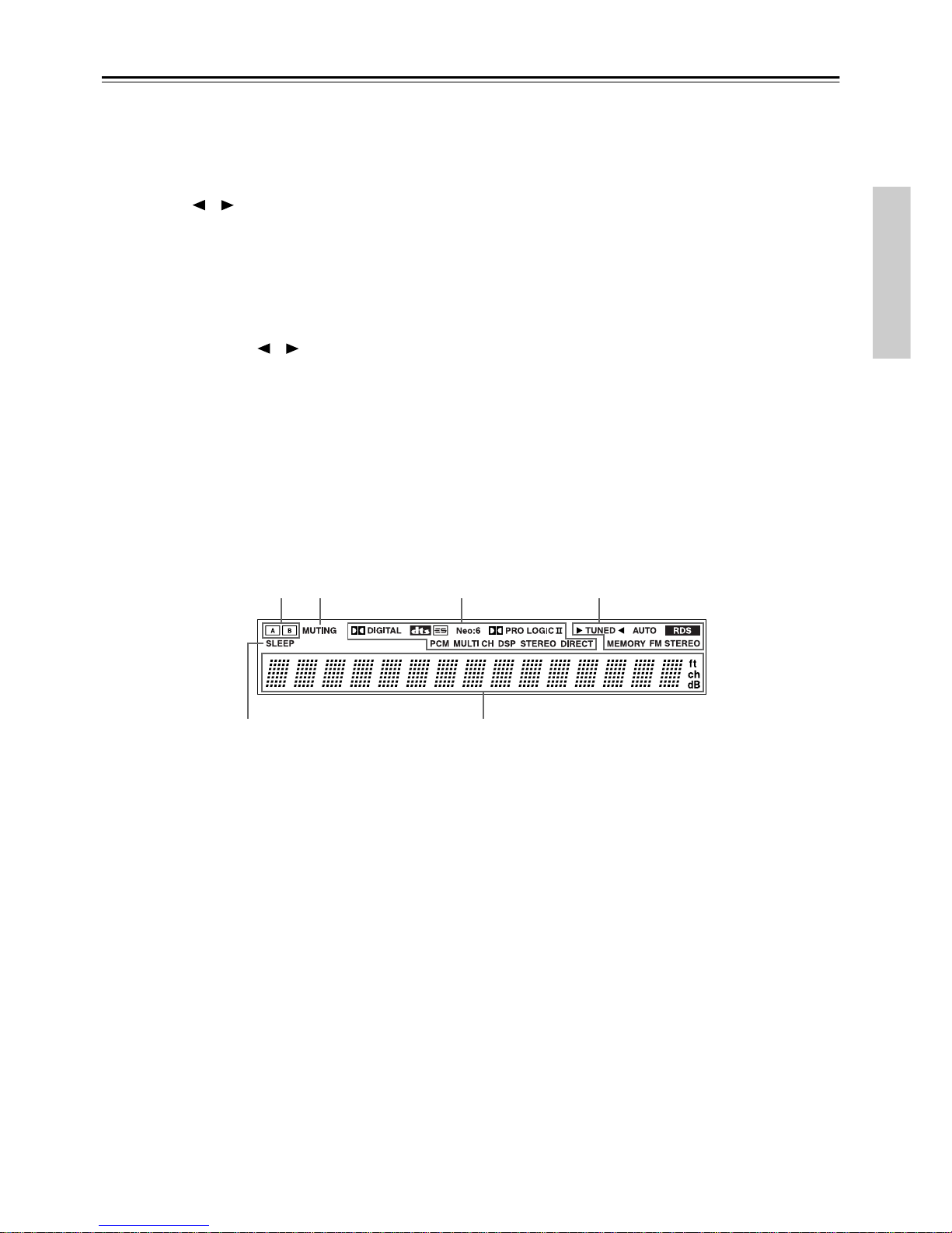
Display
For detailed information, refer to the pages in parenthesis.
1 A & B speaker indicators (28, 32)
Indicator A lights up when speaker set A is on. Indicator B
lights up when speaker set B is on.
2 MUTING indicator (33)
This indicator flashes when the TX-SR501/TX-SR501E is
muted.
3 Source/listening mode indicators (28, 36)
These indicators display information about the currently
selected source and listening mode.
4 Tuning indicators (30, 31)
TUNED (30): This indicator lights up when the TX-SR501/
TX-SR501E is tuned into a radio station.
AUTO (30): This indicator lights up when the Auto Tuning
function is on.
RDS (European model only) (31): This indicator lights
up when the TX-SR501E is tuned into a radio station that supports RDS (Radio Data System).
MEMORY (31): This indicator lights up when programming
radio presets.
FM STEREO (31): This indicator lights up when the
TX-SR501/TX-SR501E is tuned into a stereo FM station.
5 SLEEP indicator (33)
This indicator lights up when the Sleep function has been set.
6 Message area
This area of the display shows various information about the
currently selected source.
12 3 4
56
8
Controls & Connectors—Continued
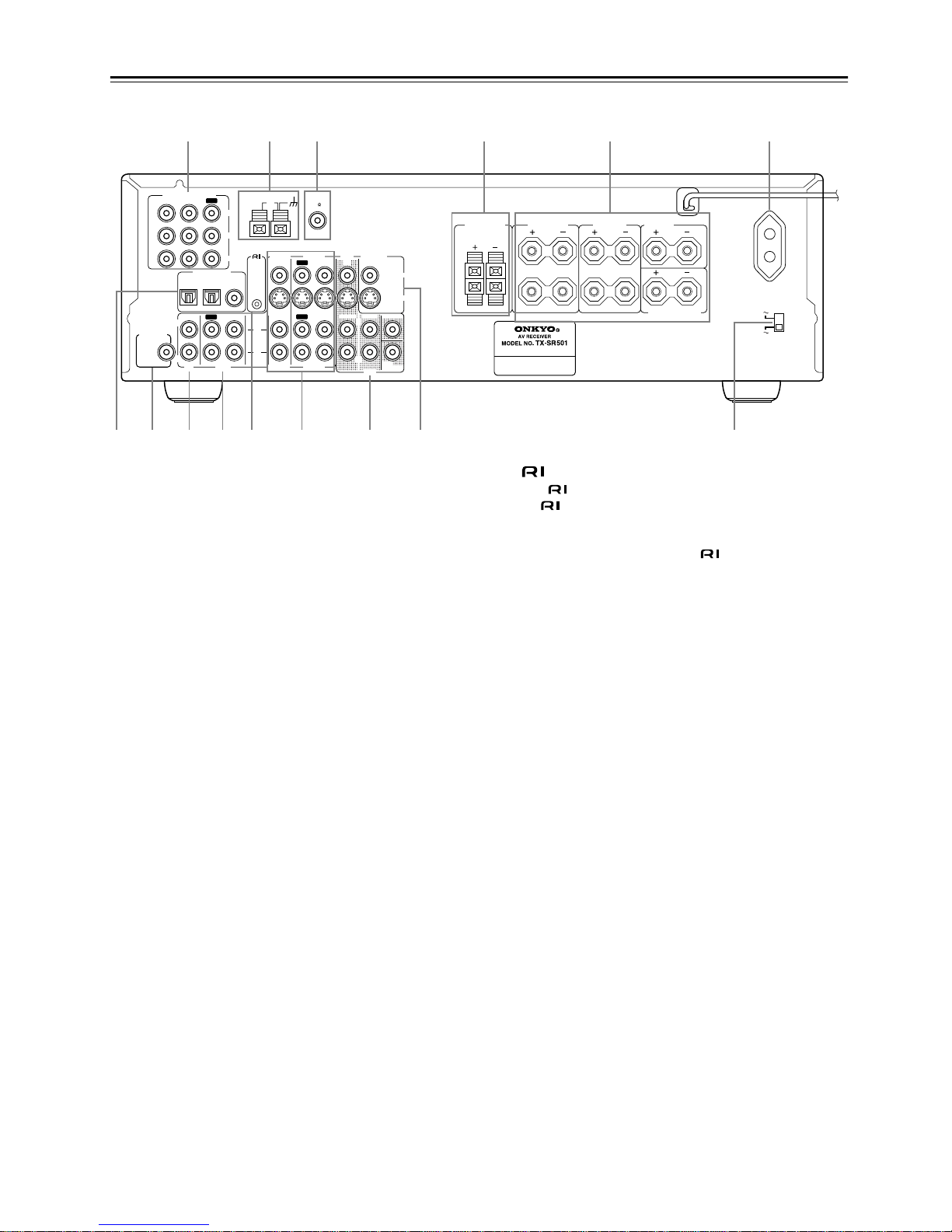
Rear Panel
For detailed information, refer to the pages in parenthesis.
A COMPONENT VIDEO (10, 12, 14, 16)
These RCA/phono connectors can be used to connect a TV,
DVD player, or other AV component with component video
inputs and outputs.
B AM ANTENNA (22, 23)
These push terminals are for connecting an AM antenna.
C FM ANTENNA (22, 23)
This connector is for connecting an FM antenna.
D FRONT SPEAKERS B (21)
These push terminals are for connecting speaker set B.
E FRONT SPEAKERS A, SURROUND SPEAKERS,
CENTER SPEAKER & SURROUND BACK
SPEAKER (21)
These terminal posts are for connecting speaker set A, including the front, surround, center, and surround-back speakers.
They accept bare wires or banana plugs (European models
don’t accept banana plugs).
F AC OUTLET (11)
This switched AC outlet can be used to supply power to
another AV component. The connector type depends on the
country in which you purchased your TX-SR501/
TX-SR501E.
G DIGITAL INPUT OPTICAL 1, 2 & COAXIAL (10,
13, 14, 16–18)
These optical and coaxial connectors can be used to connect a
CD, DVD, or LD (laser disc) player, or other AV component
with digital outputs.
H SUBWOOFER PRE OUT (21)
This RCA/phono connector can be used to connect an active
subwoofer.
I CD IN (10, 17)
These RCA/phono connectors can be used to connect a CD
player with analog outputs.
J TAPE IN/OUT (10, 17, 18)
These RCA/phono connectors can be used to connect a cassette recorder, MiniDisc recorder, or other recorder with analog inputs and outputs.
K (19)
This (Remote Interactive) connector can be connected to
the connector on another Onkyo AV component, for
example, a CD player, DVD player, or cassette recorder. The
TX-SR501/TX-SR501E’s remote controller can then be used
to control that component. To use , you must make an analog RCA/phono connection between your TX-SR501/
TX-SR501E and the other AV component, even if they are
connected digitally.
L VIDEO 1 IN/OUT & VIDEO 2 IN (10, 14–16, 39)
These connectors can be used to connect a VCR or other AV
component. There are RCA/phono connectors for connecting
to stereo analog audio inputs and outputs, and S-Video and
composite video (RCA/phono) connectors for connecting to
video inputs and outputs.
M DVD IN/MULTI CH INPUT (10, 12, 13)
The FRONT, SURR, CENTER, and SUBWOOFER RCA/
phono connectors can be used to connect AV components with
multiple analog audio outputs, including DVD players with
individual 5.1 surround analog outputs. There’s an S-Video
input and composite video (RCA/phono) input for connecting
the video signal.
N MONITOR OUT (10, 12)
These S-Video and composite video (RCA/phono) outputs can
be connected to the video input on your TV or projector.
O VOLTAGE SELECTOR (Worldwide model only)
(5)
This voltage selector provides compatibility with power systems around the world.
Tip:
A turntable with a built-in preamp can be connected to a pair of
unused TX-SR501/TX-SR501E analog inputs. To connect a
turntable without a built-in preamp, you’ll need a commercially available phono preamp. See pages 17 and 18 and the
instructions supplied with your phono preamp and turntable for
more information.
L
R
R
L
R
L
ANTENNA
FM
75
AM
FRONT
SPEAKERS A
FRONT
SPEAKERS B
SURROUND
SPEAKERS
CENTER
SPEAKER
R
L
SURROUND BACK
SPEAKER
REMOTE
CONTROL
IN
IN
IN
OPTICAL COAXIAL
12
IN
IN
IN
IN
FRONT
SURR
CENTER
SUB
WOOFER
OUT
OUT
OUT
DIGITAL INPUT
VIDEO 2
VIDEO 1
DVD MONITOR
OUT
VIDEO
S VIDEO
DVD
TAPE
CD
L
R
VIDEO 2
VIDEO 1
SUBWOOFER
PRE OUT
VIDEO 1
/2/3
IN
DVD IN
COMPONENT VIDEO
Y
P
B
PR
OUT
L
R
SWITCHED
100W MAX.
AC OUTLET
120 V
VOLTAGE
SELECTOR
220-230 V
1 6
789JK M N O
4532
L
Worldwide
model only
9
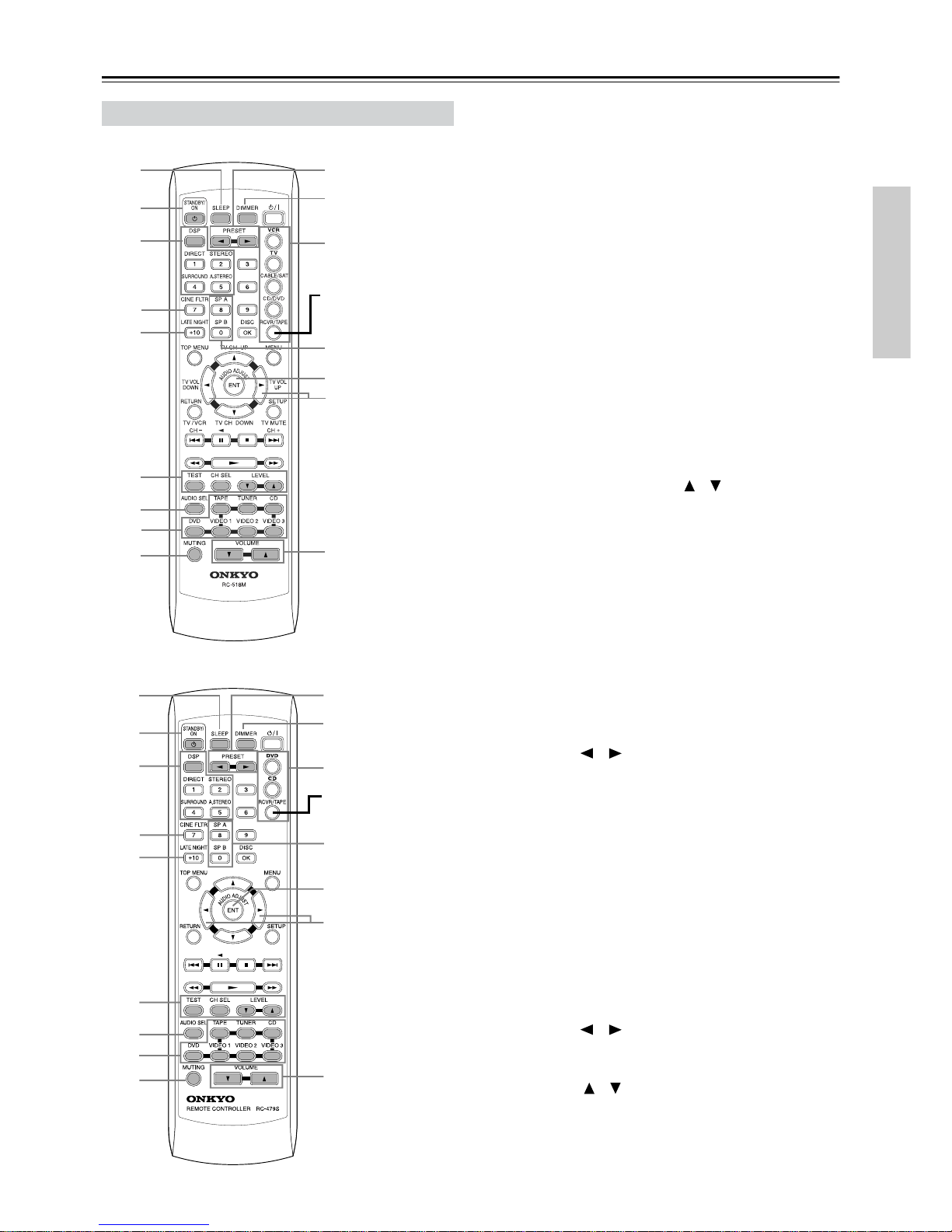
Controls & Connectors—Continued
RC-518M (North American model)
RC-479S (other models)
This page describes only those buttons that can be used to
control the TX-SR501/TX-SR501E when the remote controller is in RCVR mode (Receiver mode). The other modes,
and information on using the remote controller to control
your other AV components, are explained on page 40.
To select RCVR mode, press the [RCVR] button.
For detailed information, refer to the pages in parenthesis.
A SLEEP button (33)
This button is used to set the Sleep function. This function can
be set only with the remote controller.
B STANDBY/ON button (24)
This button is used to set the TX-SR501/TX-SR501E to On or
Standby.
C Listening mode buttons (36)
These buttons are used to select the listening modes.
D CINE FLTR button (37)
This button is used to set the Cinema Filter function.
E LATE NIGHT button (37)
This button is used to set the Late Night function.
F TEST, CH SEL & LEVEL [ ] [ ] buttons (27, 29,
33)
These buttons are used to set the level of each speaker individually. This function can be set only with the remote controller.
G AUDIO SEL button (29)
This button is used to select analog or digital inputs for the
CD, DVD, TAPE, VIDEO 1, VIDEO 2, and VIDEO 3 sources.
H Input selector buttons (28, 30, 39)
These buttons are used to select the audio and video sources:
CD, DVD, TAPE, TUNER, VIDEO 1, VIDEO 2, and
VIDEO 3.
I MUTING button (33)
This button is used to mute the TX-SR501/TX-SR501E. This
function can be set only with the remote controller.
J PRESET [ ] [ ] buttons (31)
These buttons are used to select radio presets.
K DIMMER button (32)
This button is used to adjust the display brightness.
L Remote Controller Mode buttons (28, 40, 42)
These buttons are used to select the remote controller modes.
To select RCVR mode, press the [RCVR] button.
M SP A & SP B buttons (28, 32)
These buttons are used to turn on and off speaker sets A and B
individually.
N AUDIO ADJUST button (37)
This button is used to set the Bass, Treble, Late Night, Cinema
Filter, Center Image, Panorama, Dimension, and Center Width
functions.
O ADJUST [ ] [ ] buttons (37)
These buttons are used to adjust the functions selected with
the AUDIO ADJUST button.
P VOLUME [ ] [ ] buttons (27, 28, 33)
These buttons are used to set the volume of the TX-SR501/
TX-SR501E.
Remote Controller—RCVR Mode
1J
K
2
3
4
5
M
O
6
7
9
L
N
P
8
Press this to select
RCVR mode
1J
K
2
3
4
5
M
O
6
7
9
L
N
P
8
Press this to select
RCVR mode

10
Connecting Your AV Components
• Read the manuals supplied with your AV components.
• Don’t connect the power cord until you’ve completed all
audio and video connections.
Optical Digital Inputs
The TX-SR501/TX-SR501E’s optical digital connectors
have a shutter-type cover that opens when an optical plug is
inserted, and closes when it’s removed. Push the plug in all
the way.
RCA/phono AV Connection Color Coding
RCA/phono AV connections are usually color coded: red,
white, and yellow. Use red plugs to connect right-channel
audio inputs and outputs (typically labeled “R”). Use white
plugs to connect left-channel audio inputs and outputs (typically labeled “L”). And use yello w plugs to connect composite video inputs and outputs.
• Push the plugs in all the way to make
a good connection.
•To prevent interference, keep audio
and video cables away from power
cords and speaker cables.
Before Making Any Connections
Analog audio
Right (red)
Left (white)
(Yellow)
Right (red)
Left (white)
(Yellow)
Composite video
Wrong!
Right!
AV Cables & Connectors
Video
Component
video
Component video separates the luminance (Y) and color
difference signals (PR, PB), providing the best picture
quality. Some TV manufacturers label their component
video inputs differently.
S-Video
S-Video provides better picture quality than composite
video.
Composite
video
Composite video can be found on virtually all TVs,
VCRs, and video equipment.
Audio
Optical digital
Optical digital audio connections provide better audio
quality than analog connections. Audio quality is the
same as for coaxial.
Coaxial digital
Coaxial digital audio connections provide better audio
quality than analog connections. Audio quality is the
same as for optical.
Analog
RCA/phono analog audio connectors can be found on
virtually all AV components.
Multi-channel
connection
To connect an AV component with multiple analog audio
outputs, for example, a DVD player with individual 5.1
surround analog outputs, you need to make six connections, which can be done with three stereo RCA/phono
audio cables.
C
R
C
B
Y
C
R
C
B
P
R
P
B
P/ /
//
R
P
B
Y
YPB PR
S VIDEO
VIDEO
OPTICAL
COAXIAL
LR
AUDIO
FRONT
SURR
CENTER
SUB
WOOFER
L
R
11
Connecting Your AV Components—Continued
The TX-SR501/TX-SR501E offers several connection formats for compatibility with a wide range of AV equipment.
The format you choose will depend on the formats supported
by your AV components. Use the following sections as a
guide.
When connecting video equipment, you need to make video
and audio connections.
Video Connection Formats
Video equipment can be connected to the TX-SR501/
TX-SR501E using the following video connection formats:
composite video, S-Video, or component video, the latter
offering the best picture quality.
When choosing a connection format, bear in mind that the
TX-SR501/TX-SR501E doesn’t conv ert between formats, so
only output connectors of the same format as the input connector will output a signal, as shown below.
For example, if you connect your DVD player to the
S-VIDEO DVD IN, a video signal will be output by the
S-VIDEO MONITOR OUT (for your TV) and the S-VIDEO
VIDEO 1 OUT (for your VCR), but not the composite video
or component video outputs.
Audio Connection Formats
Audio equipment can be connected to the TX-SR501/
TX-SR501E using the following audio connection formats:
analog, optical, coaxial, and multi-channel (5.1).
When choosing a connection format, bear in mind that the
TX-SR501/TX-SR501E doesn’t conv ert between formats, as
shown below.
For example, audio signals connected to the OPTICAL or
COAXIAL digital input are not output by the analog TAPE
OUT connectors, so if you want to record from, for example,
your CD player, in addition to connecting it to a digital input,
you must also connect it to the analog CD IN connectors.
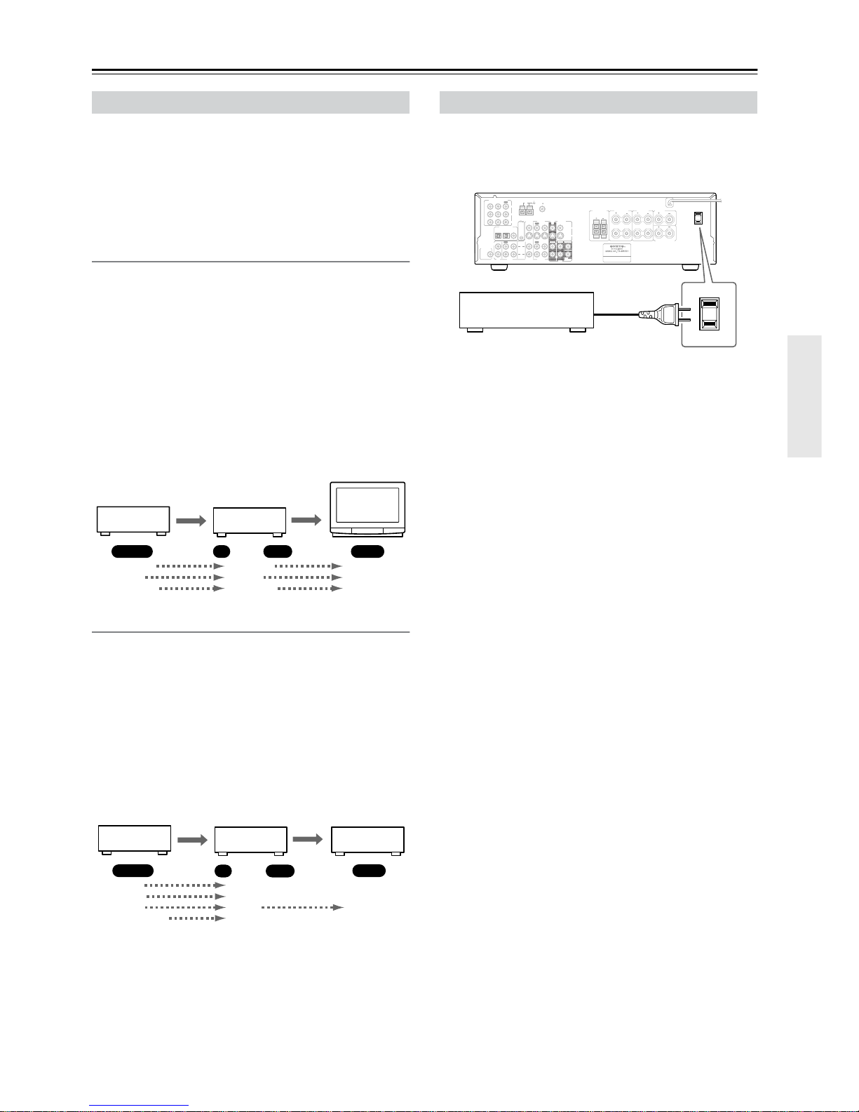
The switched AC outlet on the TX-SR501/TX-SR501E’s
rear panel can be used to supply power to another AV component, as shown. The connector type depends on the country
in which you purchased your TX-SR501/TX-SR501E.
Make sure that the wattage requirements of the AV component that you connect to the TX-SR501/TX-SR501E’s AC
outlet do not exceed the maximum wattage printed on the
rear panel.
Which Connections To Use?
TX-SR501/
TX-SR501E
DVD player,
etc.
TV,
projector,
etc.
Output InputIN OUT
Composite
S-Video
Component
Composite
S-Video
Component
Composite
S-Video
Component
DVD player,
etc.
TX-SR501/
TX-SR501E
MD recorder,
etc.
Output Input
IN OUT
Optical Not output
Coaxial Not output
Analog
Multi-channel Not output
Analog
Optical
Coaxial
Analog
Multi-channel
Using the AC OUTLET
L
R
RLR
L
ANTENNA
FM
75
AM
FRONT
SPEAKERS A
FRONT
SPEAKERS B
SURROUND
SPEAKERS
CENTER
SPEAKER
R
L
SURROUND BACK
SPEAKER
AC OUTLET
AC 120 V 60 Hz
SWITCHED
120
W 1 A
MAX.
REMOTE
CONTROL
IN
IN
IN
OPTICAL COAXIAL
12
IN
IN
IN
IN
FRONT
SURR CENTER
SUB
WOOFER
OUT
OUT
OUT
DIGITAL INPUT
VIDEO 2
VIDEO 1
DVD MONITOR
OUT
VIDEO
S VIDEO
DVD
TAPE
CD
L
R
VIDEO 2
VIDEO 1
SUBWOOFER
PRE OUT
VIDEO 1
/2/3
IN
DVD IN
COMPONENT VIDEO
Y
P
B
PR
OUT
L
R
AV component
12
Connecting Your AV Components—Continued
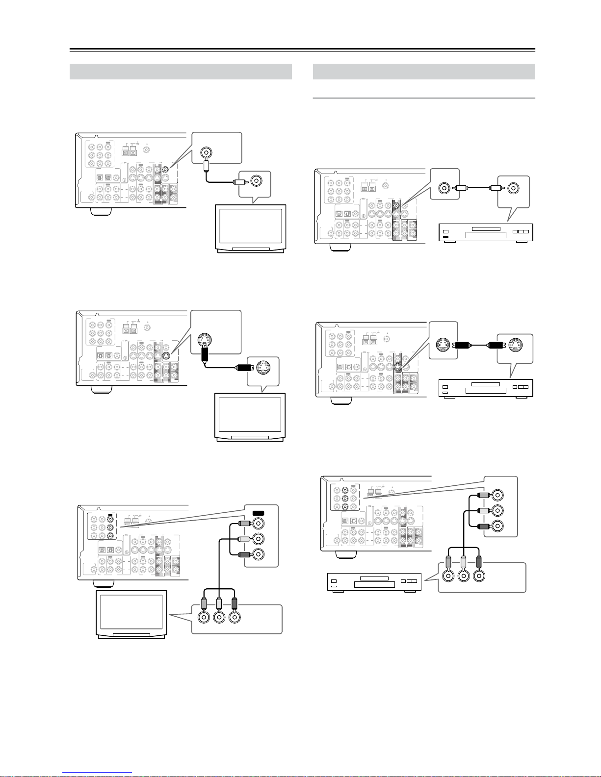
■ Using Composite Video
Use a composite video cable to connect the TX-SR501/
TX-SR501E’s VIDEO MONITOR OUT to a composite
video input on your TV, as shown.
■ Using S-Video
Use an S-Video cable to connect the TX-SR501/
TX-SR501E’s S VIDEO MONITOR OUT to an S-Video
input on your TV, as shown.
■ Using Component Video
Use a component video cable to connect the TX-SR501/
TX-SR501E’s COMPONENT VIDEO OUT connectors to
the component video inputs on your TV, as shown.
Video Connections
■ Using Composite Video
Use a composite video cable to connect the TX-SR501/
TX-SR501E’s VIDEO DVD IN to the composite video output on your DVD player, as shown.
•Your TV must also be connected via composite video.
■ Using S-Video
Use an S-Video cable to connect the TX-SR501/
TX-SR501E’s S VIDEO DVD IN to the S-Video output on
your DVD player, as shown.
•Your TV must also be connected via S-Video.
■ Using Component Video
Use a component video cable to connect the TX-SR501/
TX-SR501E’s COMPONENT DVD IN connectors to the
component video outputs on your DVD player, as shown.
•Your TV must also be connected via component video.
Connecting Your TV or Projector
L
R
ANTENNA
FM
75
AM
REMOTE
CONTROL
IN
IN
IN
OPTICAL COAXIAL
12
IN
IN
IN
IN
FRONT
SURR
CENTER
SUB
WOOFER
OUT
OUT
OUT
DIGITAL INPUT
VIDEO 2
VIDEO 1
DVD MONITOR
OUT
VIDEO
S VIDEO
DVD
TAPE
CD
L
R
VIDEO 2
VIDEO 1
SUBWOOFER
PRE OUT
VIDEO 1
/2/3
IN
DVD IN
COMPONENT VIDEO
Y
P
B
PR
OUT
L
R
MONITOR
OUT
VIDEO
VIDEO IN
TV, projector, etc.
L
R
ANTENNA
FM
75
AM
REMOTE
CONTROL
IN
IN
IN
OPTICAL COAXIAL
12
IN
IN
IN
IN
FRONT
SURR
CENTER
SUB
WOOFER
OUT
OUT
OUT
DIGITAL INPUT
VIDEO 2
VIDEO 1
DVD MONITOR
OUT
VIDEO
S VIDEO
DVD
TAPE
CD
L
R
VIDEO 2
VIDEO 1
SUBWOOFER
PRE OUT
VIDEO 1
/2/3
IN
DVD IN
COMPONENT VIDEO
Y
P
B
PR
OUT
L
R
MONITOR
OUT
S VIDEO
S VIDEO IN
TV, projector, etc.
L
R
ANTENNA
FM
75
AM
REMOTE
CONTROL
IN
IN
IN
OPTICAL COAXIAL
12
IN
IN
IN
IN
FRONT
SURR
CENTER
SUB
WOOFER
OUT
OUT
OUT
DIGITAL INPUT
VIDEO 2
VIDEO 1
DVD MONITOR
OUT
VIDEO
S VIDEO
DVD
TAPE
CD
L
R
VIDEO 2
VIDEO 1
SUBWOOFER
PRE OUT
VIDEO 1
/2/3
IN
DVD IN
COMPONENT VIDEO
Y
P
B
PR
OUT
L
R
Y
OUT
YPB PR
PB
PR
COMPONENT
VIDEO IN
TV, projector, etc.
Connecting a DVD player
L
R
ANTENNA
FM
75
AM
REMOTE
CONTROL
IN
IN
IN
OPTICAL COAXIAL
12
IN
IN
IN
IN
FRONT
SURR
CENTER
SUB
WOOFER
OUT
OUT
OUT
DIGITAL INPUT
VIDEO 2
VIDEO 1
DVD MONITOR
OUT
VIDEO
S VIDEO
DVD
TAPE
CD
L
R
VIDEO 2
VIDEO 1
SUBWOOFER
PRE OUT
VIDEO 1
/2/3
IN
DVD IN
COMPONENT VIDEO
Y
P
B
PR
OUT
L
R
DVD
IN
VIDEO OUT
DVD player
L
R
ANTENNA
FM
75
AM
REMOTE
CONTROL
IN
IN
IN
OPTICAL COAXIAL
12
IN
IN
IN
IN
FRONT
SURR
CENTER
SUB
WOOFER
OUT
OUT
OUT
DIGITAL INPUT
VIDEO 2
VIDEO 1
DVD MONITOR
OUT
VIDEO
S VIDEO
DVD
TAPE
CD
L
R
VIDEO 2
VIDEO 1
SUBWOOFER
PRE OUT
VIDEO 1
/2/3
IN
DVD IN
COMPONENT VIDEO
Y
P
B
PR
OUT
L
R
IN
DVD
S VIDEO OUT
DVD player
L
R
ANTENNA
FM
75
AM
REMOTE
CONTROL
IN
IN
IN
OPTICAL COAXIAL
12
IN
IN
IN
IN
FRONT
SURR
CENTER
SUB
WOOFER
OUT
OUT
OUT
DIGITAL INPUT
VIDEO 2
VIDEO 1
DVD MONITOR
OUT
VIDEO
S VIDEO
DVD
TAPE
CD
L
R
VIDEO 2
VIDEO 1
SUBWOOFER
PRE OUT
VIDEO 1
/2/3
IN
DVD IN
COMPONENT VIDEO
Y
P
B
PR
OUT
L
R
DVD IN
Y
Y
PB PR
PB
PR
COMPONENT
VIDEO OUT
DVD player
13
Connecting Your AV Components—Continued
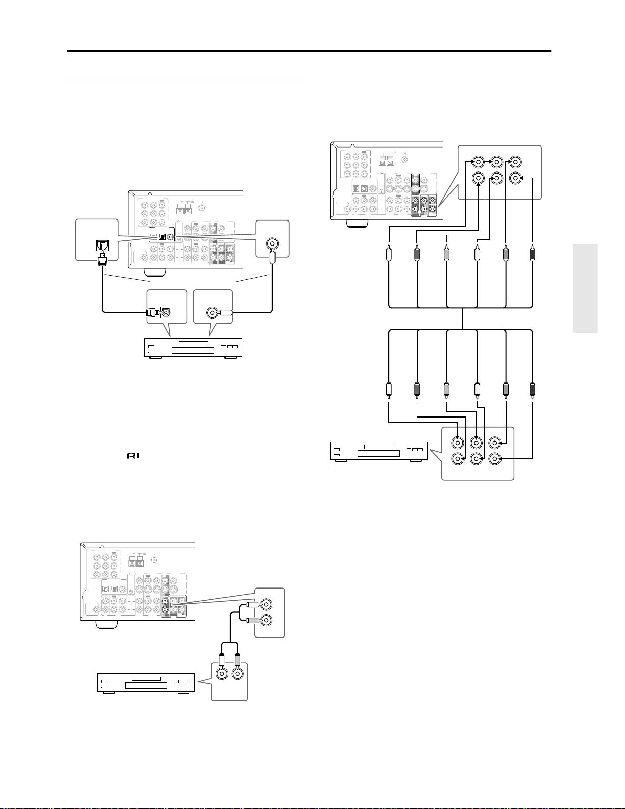
Audio Connections
■ Using Optical or Coaxial Connections
• Use an optical digital audio cable to connect the
TX-SR501/TX-SR501E’s OPTICAL 1 DIGITAL INPUT
to the optical output on your DVD player, as shown.
OR
• Use a coaxial digital audio cable to connect the TX-SR501/
TX-SR501E’s CO AXIAL DIGIT AL INPUT to the coaxial
output on your DVD player, as shown.
Initially, the OPTICAL 1 digital input is assigned to the DVD
input source. If you connect your DVD player to a different
digital input, you’ll need to assign that input to the DVD
input source (see page 24).
■ Using Analog Connections
Even if your DVD player is connected digitally (coaxial or
optical), to use , or to record audio from your DVD
player, you’ll need to make analog connections as well.
Use an RCA/phono audio cable to connect the TX-SR501/
TX-SR501E’s FRONT DVD IN connectors to the analog
audio outputs on your DVD player, as shown.
If your DVD player has L/R outputs and multi-channel 5.1
outputs, be sure to use the L/R outputs.
■ Using Multi-channel Connections
Use a multi-channel RCA/phono audio cable to connect the
TX-SR501/TX-SR501E’s L/R FRONT, L/R SURR, CENTER, and SUB WOOFER D VD IN connectors to the 5.1 analog outputs on your DVD player, as shown.
Alternatively, use three stereo RCA/phono audio cables.
L
R
ANTENNA
FM
75
AM
REMOTE
CONTROL
IN
IN
IN
OPTICAL COAXIAL
12
IN
IN
IN
IN
FRONT
SURR
CENTER
SUB
WOOFER
OUT
OUT
OUT
DIGITAL INPUT
VIDEO 2
VIDEO 1
DVD MONITOR
OUT
VIDEO
S VIDEO
DVD
TAPE
CD
L
R
VIDEO 2
VIDEO 1
SUBWOOFER
PRE OUT
VIDEO 1
/2/3
IN
DVD IN
COMPONENT VIDEO
Y
P
B
PR
OUT
L
R
COAXIAL
OPTICAL
1
DIGITAL OUT
OPTICAL
DIGITAL OUT
COAXIAL
DVD player
Connect one or the other
L
R
ANTENNA
FM
75
AM
REMOTE
CONTROL
IN
IN
IN
OPTICAL COAXIAL
12
IN
IN
IN
IN
FRONT
SURR
CENTER
SUB
WOOFER
OUT
OUT
OUT
DIGITAL INPUT
VIDEO 2
VIDEO 1
DVD MONITOR
OUT
VIDEO
S VIDEO
DVD
TAPE
CD
L
R
VIDEO 2
VIDEO 1
SUBWOOFER
PRE OUT
VIDEO 1
/2/3
IN
DVD IN
COMPONENT VIDEO
Y
P
B
PR
OUT
L
R
LR
FRONT
DVD
L
R
AUDIO
OUTPUT
DVD player
L
R
ANTENNA
FM
75
AM
REMOTE
CONTROL
IN
IN
IN
OPTICAL COAXIAL
12
IN
IN
IN
IN
FRONT
SURR
CENTER
SUB
WOOFER
OUT
OUT
OUT
DIGITAL INPUT
VIDEO 2
VIDEO 1
DVD MONITOR
OUT
VIDEO
S VIDEO
DVD
TAPE
CD
L
R
VIDEO 2
VIDEO 1
SUBWOOFER
PRE OUT
VIDEO 1
/2/3
IN
DVD IN
COMPONENT VIDEO
Y
P
B
PR
OUT
L
R
FRONT
SURR CENTER
SUB
WOOFER
DVD
L
R
FRONT
SURR
CENTER
SUB
WOOFER
LRL
R
DVD player
FRONT R
FRONT L
SURR L
CENTER
SURR R
SUBWOOFER
FRONT R
FRONT L
SURR L
CENTER
SURR R
SUBWOOFER
14
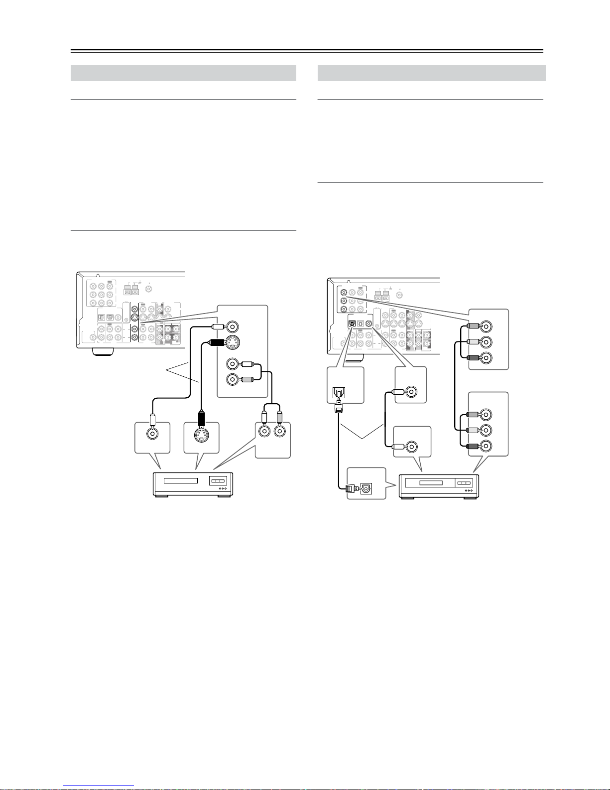
Connecting Your AV Components—Continued
Video Connections
• Use an S-Video cable to connect the TX-SR501/
TX-SR501E’s S VIDEO VIDEO 2 IN to the S-Video output on your VCR, as shown. Your TV must also be connected via S-Video.
OR
• Use a composite video cable to connect the TX-SR501/
TX-SR501E’s VIDEO VIDEO 2 IN to a composite video
output on your VCR, as sho wn. Your TV must also be connected via composite video.
Audio Connections
Use an RCA/phono audio cable to connect the TX-SR501/
TX-SR501E’s L/R VIDEO 2 IN connectors to the analog
audio outputs on your VCR, as shown.
Video connections
Use a component video cable to connect the TX-SR501/
TX-SR501E’s COMPONENT VIDEO 1/2/3 IN connectors
to the component video outputs on your D-VHS recorder, as
shown.
•Your TV must also be connected via component video.
Audio connections
• Use a coaxial digital audio cable to connect the TX-SR501/
TX-SR501E’s CO AXIAL DIGIT AL INPUT to the coaxial
output on your D-VHS recorder, as shown.
OR
• Use an optical digital audio cable to connect the
TX-SR501/TX-SR501E’s OPTICAL 2 DIGITAL INPUT
to the optical output on your D-VHS recorder, as shown.
You may need to change the input source to digital input
assignments (see page 24).
Connecting a VCR for Playback
L
R
ANTENNA
FM
75
AM
REMOTE
CONTROL
IN
IN
IN
OPTICAL COAXIAL
12
IN
IN
IN
IN
FRONT
SURR
CENTER
SUB
WOOFER
OUT
OUT
OUT
DIGITAL INPUT
VIDEO 2
VIDEO 1
DVD MONITOR
OUT
VIDEO
S VIDEO
DVD
TAPE
CD
L
R
VIDEO 2
VIDEO 1
SUBWOOFER
PRE OUT
VIDEO 1
/2/3
IN
DVD IN
COMPONENT VIDEO
Y
P
B
PR
OUT
L
R
LR
IN
IN
VIDEO 2
VIDEO 2
VIDEO
S VIDEO
S VIDEO OUT
VIDEO OUT
AUDIO
OUTPUT
VCR
Connect one
or the other
Connecting a D-VHS Recorder
L
R
ANTENNA
FM
75
AM
REMOTE
CONTROL
IN
IN
IN
OPTICAL COAXIAL
12
IN
IN
IN
IN
FRONT
SURR
CENTER
SUB
WOOFER
OUT
OUT
OUT
DIGITAL INPUT
VIDEO 2
VIDEO 1
DVD MONITOR
OUT
VIDEO
S VIDEO
DVD
TAPE
CD
L
R
VIDEO 2
VIDEO 1
SUBWOOFER
PRE OUT
VIDEO 1
/2/3
IN
COMPONENT VIDEO
Y
P
B
PR
OUT
L
R
OPTICAL
2
VIDEO 1
/2/3
IN
Y
P
B
PR
COAXIAL
Y
P
B
PR
DIGITAL OUT
OPTICAL
DIGITAL OUT
COAXIAL
COMPONENT
VIDEO OUT
D-VHS recorder
Connect one
or the other
15
Connecting Your AV Components—Continued
If your TV has AV outputs and you want to record from your
TV to your VCR via the TX-SR501/TX-SR501E, make the
following connections.
• Use an S-Video cable to connect the TX-SR501/
TX-SR501E’s S VIDEO VIDEO 2 IN to an S-V ideo output
on your TV, and use another S-Video cable to connect the
TX-SR501/TX-SR501E’s S VIDEO VIDEO 1 OUT to an
S-Video input on your VCR, as shown.
OR
• Use a composite video cable to connect the TX-SR501/
TX-SR501E’s VIDEO VIDEO 2 IN to a composite video
output on your TV, and use another composite video cable
to connect the TX-SR501/TX-SR501E’s VIDEO VIDEO 1
OUT to a composite video input on your VCR, as shown.
Use an RCA/phono audio cable to connect the TX-SR501/
TX-SR501E’s L/R VIDEO 2 IN connectors to the analog
audio outputs on your TV, and use another RCA/phono audio
cable to connect the TX-SR501/TX-SR501E’s L/R VIDEO 1
OUT connectors to the analog audio inputs on your VCR, as
shown.
Note:
The TX-SR501/TX-SR501E must be turned on (not
Standby) in order to record.
If you want to record from your TV to your VCR without
going through the TX-SR501/TX-SR501E, connect your
TV’s AV outputs directly to your VCR’s AV inputs. See the
manuals supplied with your TV and VCR for details.
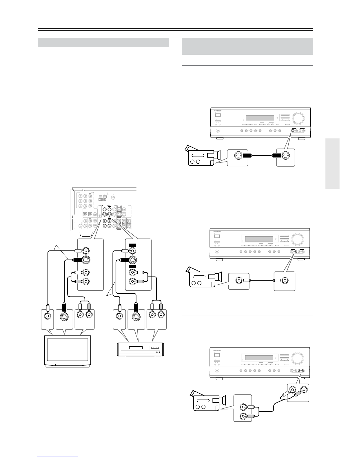
Video Connections
■ Using S-Video
Use an S-Video cable to connect the TX-SR501/
TX-SR501E’s S VIDEO VIDEO 3 INPUT to the S-Video
output on your camcorder, games console, etc., as shown.
•Your TV must also be connected via S-Video.
■ Using Composite Video
Use a composite video cable to connect the TX-SR501/
TX-SR501E’s VIDEO VIDEO 3 INPUT to the composite
video output on your camcorder, games console, etc., as
shown.
•Your TV must also be connected via composite video.
Audio Connections
Use an RCA/phono audio cable to connect the TX-SR501/
TX-SR501E’s L/R VIDEO 3 INPUT connectors to the analog audio outputs on your camcorder, games console, etc., as
shown.
Connecting a VCR for Recording
L
R
ANTENNA
FM
75
AM
REMOTE
CONTROL
IN
IN
IN
OPTICAL COAXIAL
12
IN
IN
IN
IN
FRONT
SURR
CENTER
SUB
WOOFER
OUT
OUT
OUT
DIGITAL INPUT
VIDEO 2
VIDEO 1
DVD MONITOR
OUT
VIDEO
S VIDEO
DVD
TAPE
CD
L
R
VIDEO 2
VIDEO 1
SUBWOOFER
PRE OUT
VIDEO 1
/2/3
IN
DVD IN
COMPONENT VIDEO
Y
P
B
PR
OUT
L
R
LR
VIDEO 1
VIDEO
S VIDEO
VIDEO
S VIDEO
IN
IN
VIDEO 2
VIDEO 1VIDEO 2
LR
OUT
OUT
S VIDEO
OUT
VIDEO
OUT
AUDIO
OUTPUT
S VIDEO
IN
VIDEO
IN
AUDIO
INPUT
TV
VCR
Connect one
or the other
Connect one
or the other
Connecting a Camcorder, Games
Console, etc.
STANDBY/ON
PHONES
MASTER VOLUME
VIDEO
2
TAPE TUNER
C
D
VIDEO
3
DVD
DIMMER
SURROUND
VIDEO 1
VCR
AUDIO
SELECTOR
DSP
STEREO
STANDBY
DISPLAY
AUDIO ADJUST
SPEAKER ADJUST
SUBWOOFER
LEVEL CONTROL
SUBWOOFER
MODE
DIGITAL INPUT
CH SEL
DIRECT
S VIDEO AUDIO
VIDEO L R
LEVEL
ADJUST
VIDEO 3
INPUT
AB
SPEAKERS
OFFON
POWER
S VIDEO
S VIDEO OUT
Camcorder,
games console, etc.
STANDBY/ON
PHONES
MASTER VOLUME
VIDEO
2
TAPE TUNER
C
D
VIDEO
3
DVD
DIMMER
SURROUND
VIDEO 1
VCR
AUDIO
SELECTOR
DSP
STEREO
STANDBY
DISPLAY
AUDIO ADJUST
SPEAKER ADJUST
SUBWOOFER
LEVEL CONTROL
SUBWOOFER
MODE
DIGITAL INPUT
CH SEL
DIRECT
S VIDEO AUDIO
VIDEO LR
LEVEL
ADJUST
VIDEO 3
INPUT
AB
SPEAKERS
OFFON
POWER
VIDEO
VIDEO OUT
Camcorder,
games console, etc.
STANDBY/ON
OFFON
POWER
PHONES
MASTER VOLUME
VIDEO
2
TAPE TUNER
C
D
VIDEO
3
DVD
DIMMER
SURROUND
VIDEO 1
VCR
AUDIO
SELECTOR
DSP
STEREO
STANDBY
DISPLAY
AUDIO ADJUST
SPEAKER ADJUST
SUBWOOFER
LEVEL CONTROL
SUBWOOFER
MODE
DIGITAL INPUT
CH SEL
DIRECT
S VIDEO AUDIO
VIDEO LR
LEVEL
ADJUST
VIDEO 3
INPUT
L
R
AUDIO
LR
AUDIO
OUTPUT
AB
SPEAKERS
Camcorder,
games console, etc.
 Loading...