

Page 1
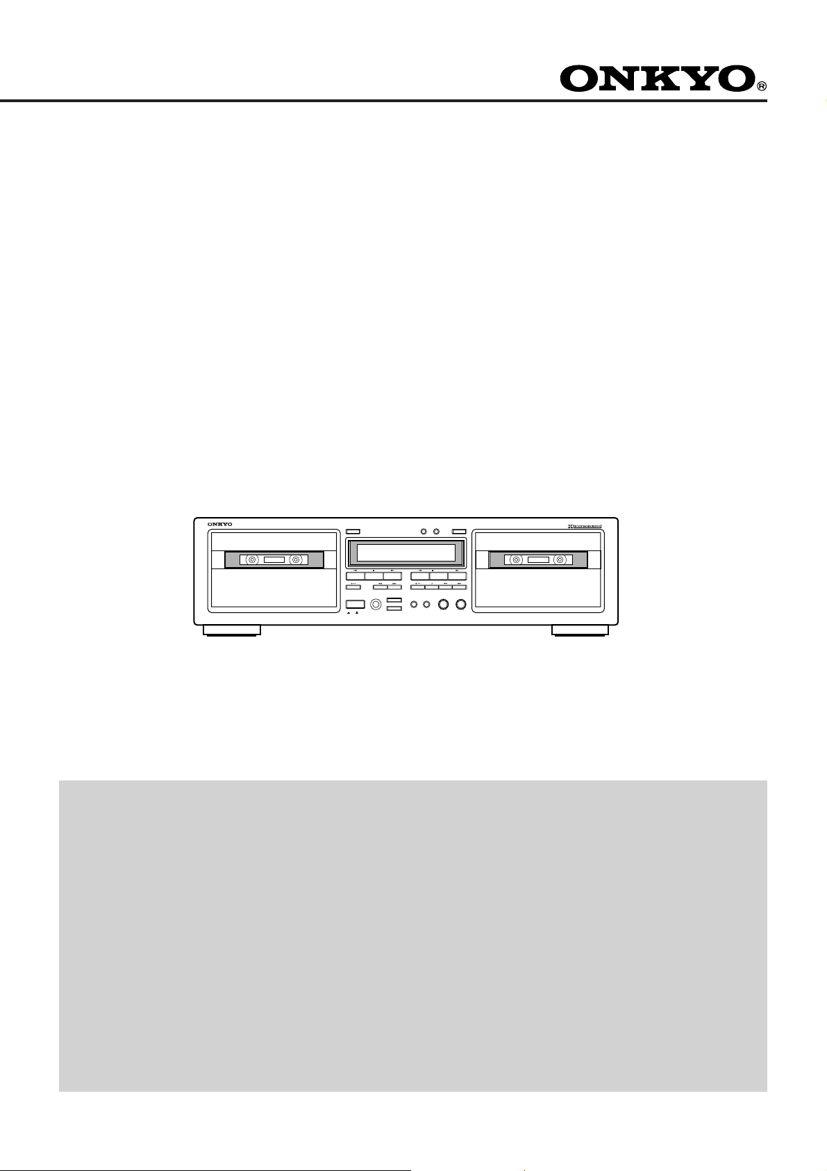
TA-RW544/344
Stereo Cassette Tape Deck
Instruction Manual
EJECT EJECT
DECK A DECK B
2 MOTER COMPUTER CONTROL
AUTO REVERSE
POWER
REVERSE MODE
PHONES
DOLBY NR
OFF
ON
CONTENTS
Features................................................ 2
Important Safeguards........................... 3
Precautions .......................................... 3
Control Positions and Names .............. 4
Setting the Voltage Selector ................ 5
System Connections ............................ 5
Power Connections .............................. 5
To Play a Tape..................................... 6
Useful Functions Available during Playback
(TA-RW544 Only) ..............................................
Recording ............................................ 8
7
DECK A/B RESET
//
DUBBING
NORMAL HIGH
DUBB. STOP
REC BALANCE REC LEVEL
L R MIN
MAX
2 MOTER COMPUTER CONTROL
AUTO REVERSE
STEREO CASSETTE TAPE DECK
TA-RW544
Tape Dubbing .................................... 12
Useful Recording Functions .............. 13
Making Good Sound Recordings ...... 13
Connecting ONKYO Components
for z Components........................... 14
CD Synchro Recording System......... 14
Reverse Mode Function..................... 15
Handling Cassette Tapes ................... 16
Cassette Deck Maintenance............... 17
Specifications .................................... 17
Troubleshooting Guide ...................... 18
1
Page 2

Thank you for your purchase of the
ONKYO TA-RW544/344 Cassette Tape Deck.
Please read this manual thoroughly before making connections
and plugging in the AC power cord.
Following the instructions in this manual will enable you to
obtain optimum performance and maximum listening enjoyment
from your new TA-RW544/344.
Please retain this manual for future reference.
Features
Convenient dubbing & nonstop music
Excellent performance is not this deck’s singular feature.
The TA-RW544 is two outstanding recording decks in one.
So you can make a copy for yourself and one for a friend at
the same time. Or keep recording or playing tape after tape
with its dual auto reverse (to capture and enjoy those longer
shows).
Rugged 2 x 2 motor transport system
Separate capstan and reel motors for each transport not only
prevent overloading, they provide the precise tape movement needed for accurate reproduction. They also contribute
to the long-life, trouble-free performance that ONKYO
cassette decks are famous for.
Dolby HX Pro headroom extension
Dolby HX Pro extends the dynamic headroom to capture the
wider musical dynamics of CDs and other digital sources. It
provides noticeably cleaner reproduction of those crucial
higher frequencies by improving the tape’s ability to capture
high-level signals without saturation. Another plus is the
tapes you record with Dolby HX Pro can be played back on
decks without Dolby HX Pro, for improved sound performance.
Music search (TA-RW544 only)
When you’re playing a tape back, our Music Search system
does just what you might expect—lets you automatically
skip forward or backward to easily find the exact beginning
of each selection. It works by sensing pauses between music
selections.
One-touch CD synchronized recording
This handy feature lets you effortlessly and accurately record
your favorite CDs when your deck is connected to virtually
any z compatible ONKYO CD player.
z (Remote Interactive) system compatible
As might be expected, the TA-RW544/344 is fully compatible with ONKYO’s z (Remote Interactive) system. This
means you can control virtually all of the cassette deck’s
major functions with other ONKYO remote controls.
Other features
• Auto tape selector: Automatically sets bias and equaliza-
tion for the type of tape you insert.
• Auto spacing: Handy for inserting blank spaces when re-
recording or editing tapes, or recording from CDs, records
and the radio.
• Headphone jack: For private listening.
• Full repeat: Repeats both A and B sides of both transports
up to eight times, then shuts off automatically.
• 8-segment fluorescent peak metering: Allows you to
accurately adjust recording levels for optimum performance.
Declaration of Conformity
We,
ONKYO EUROPE
ELECTRONICS GMBH
INDUSTRIESTRASSE 18/20
82110 GERMERING,
GERMANY
declare in own responsibility, that the ONKYO product described
in this instruction manual is in compliance with the corresponding
technical standards such as EN55013, EN55020, EN60555-2, -3
and EN60065
GERMERING,GERMANY
H. YAMAZOE
ONKYO EUROPE ELECTRONICS GMBH
FOR CANADIAN MODEL:
(POUR LE MODELE CANADIEN)
• For models having a power cord with a polarized plug
CAUTION: TO PREVENT ELECTRIC SHOCK, MATCH
WIDE BLADE OF PLUG TO WIDE SLOT, FULLY INSERT.
• Sur les modèles dont la fiche est polarisée.
ATTENTION: POUR ÉVITER LES CHOCS
ÉLECTRIQUES, INTRODUIRE LA LAME LA PLUS LARGE
DE LA FICHE DANS LA BORNE CORRESPONDANTE DE
LA PRISE ET POUSSER JUSQ’AU FOND.
ATTENTION FOR BRITISH MODEL
• Replacement and mounting of an AC plug on the power
supply cord of this unit should be performed only by qualified
service personnel.
• IMPORTANT: The wires in the mains lead are coloured in
accordance with the following code:
Blue: Neutral
Brown: Live
As the colours of the wires in the mains lead of this apparatus
may not correspond with the coloured markings identifying the
terminals in your plug, proceed as follows:
The wire which is coloured blue must be connected to the
terminal which is marked with the letter N or coloured black.
The wire which is coloured brown must be connected to the
terminal which is marked with the letter L or coloured red.
IMPORTANT
A 5 amp fuse is fitted in this plug. Should the fuse need to be
replaced, please ensure that the replacement fuse has a rating of 5
amps and that it is approved by ASTA or BSI to BS1362. Check
for the ASTA mark or the BSI mark on the body of the fuse.
IF THE FITTED MOULDED PLUG IS UNSUITABLE FOR
THE SOCKET OUTLET IN YOUR HOME THEN THE FUSE
SHOULD BE REMOVED AND THE PLUG CUT OFF AND
DISPOSED OF SAFELY. THERE IS A DANGER OF SEVERE
ELECTRICAL SHOCK IF THE CUT OFF PLUG IS INSERTED INTO ANY 13 AMP SOCKET.
Supplied accessory
Audio connection cable
WARNING
“TO REDUCE THE RISK OF FIRE OR ELECTRIC
SHOCK, DO NOT EXPOSE THIS APPLIANCE TO RAIN
OR MOISTURE.”
CAUTION
“TO REDUCE THE RISK OF ELECTRIC SHOCK, DO
NOT REMOVE COVER (OR BACK). NO USER-SERVICEABLE PARTS INSIDE. REFER SERVICING TO
QUALIFIED SERVICE PERSONNEL.”
2
CAUTION
RISK OF ELECTRIC SHOCK
DO NOT OPEN
• The lightning flash with arrowhead symbol, within an
equilateral triangle, is intended to alert the user to the
presence of uninsulated “dangerous voltage” within the
product’s enclosure that may be of sufficient magnitude to constitute a risk of electric shock to persons.
• The exclamation point within an equilateral triangle is
intended to alert the user to the presence of important
operating and maintenance (servicing) instructions in
the literature accompanying the appliance.
Page 3

Important Safeguards
Precautions
1. Read Instructions — All the safety and operating instructions
should be read before the appliance is operated.
2. Retain Instructions — The safety and operating instructions
should be retained for future reference.
3. Heed Warnings — All warnings on the appliance and in the
operating instructions should be adhered to.
4. Follow Instructions — All operating and use instructions should
be followed.
5. Water and Moisture — The appliance should not be used near
water — for example, near a bathtub, washbowl, kitchen sink,
laundry tub, in a wet basement, or near a swimming pool, and the
like.
6. Carts and Stands — The appliance should be used only with a
cart or stand that is recommended by the manufacturer.
6A. An appliance and cart combination should be moved with care. Quick
stops, excessive force, and uneven surface may cause the appliance
and cart combination to overturn.
PORTABLE CART WARNING
S3125A
7. Wall or Ceiling Mounting — The appliance should be mounted
to a wall or ceiling only as recommended by the manufacturer.
8. Ventilation – The appliance should be situated so that its location
or position does not interfere with its proper ventilation. For example,
the appliance should not be situated on a bed, sofa, rug, or similar
surface that may block the ventilation openings; or if placed in a
built-in installation, such as a book case or cabinet that may impede
the flow of air through the ventilation openings, there should be free
space of at least 20 cm (8 in.) and open up behind the appliance.
9. Heat — The appliance should be situated away from heat sources
such as radiators, heat registers, stoves, or other appliances (including
amplifiers) that produce heat.
10. Power Sources — The appliance should be connected to a power
supply only of the type described in the operating instructions or as
marked on the appliance.
11. Polarization — The polarization of the plug is a safety feature. The
polarized plug will only fit the outlet one way. If the plug does not fit
fully into the outlet, try reversing it. If there is still trouble inserting
it, the user should seek the services of a qualified electrician. Under
no circumstances should the user attempt to defeat the polarization of
the plug.
12. Power-Cord Protection — Power-supply cords should be routed
so that they are not likely to be walked on or pinched by items placed
upon or against them, especially near plug, convenience receptacles,
and the point where they exit from the appliance.
13. Cleaning — The appliance should be cleaned only as recom-
mended by the manufacturer.
14. Nonuse Periods — The power cord of the appliance should be
unplugged from the outlet when left unused for a long period of time.
15. Object and Liquid Entry — Care should be taken so that objects
do not fall and liquids are not spilled into the enclosure through
openings.
16. Damage Requiring Service — The appliance should be serviced
by qualified service personnel when:
A. The power-supply cord or the plug has been damaged; or
B. Objects have fallen, or liquid has been spilled into the appliance;
or
C. The appliance has been exposed to rain; or
D. The appliance does not appear to operate normally or exhibits a
marked change in performance; or
E. The appliance has been dropped, or the enclosure damaged.
17. Servicing — The user should not attempt to service the appliance
beyond that described in the operating instructions. All other
servicing should be referred to qualified service personnel.
1. Warranty Claim
You can find the serial number on the rear panel of the unit. In
case of warranty claim, please report this number.
2. Recording Copyright
Recording of copyrighted material for other than personal use is
illegal without permission of the copyright holder.
3. Deck Location
• Do not use or leave in direct sunlight or in other places
subject to high temperature and humidity. The unit should
also not be left in potentially hot places such as near heating
appliances. Excessive heat and moisture can lead to internal
damage and serious malfunctions. (This also applies to
cassette tapes.) The recommended ambient temperature range
is 5°C to 35°C.
• Avoid damp and dusty places and locations prone to vibrations.
• Be extremely careful with the recording/playback heads.
Clean and demagnetize them regularly, but under no circumstances should magnets or other metals be used anywhere
near the heads.
• This unit is extremely sensitive to magnetic fields, so do not
use near large speakers or other devices which generate
magnetic fields.
• Hum may even be included by magnetic flux leakage from
the power transformer in certain amplifiers. Therefore, this
unit should also be kept clear of the amplifier.
• Do not remove the cabinet case. If any of the internal parts
are handled, there is a considerable danger of electric shock.
4. Cassettes to Avoid:
• Cassettes with poorly formed cases that rattle during rewind
and fast forward.
• Low cost cassettes with no guide roller or pressure pad spring
should never be used for stereo.
• C-120 cassettes — because the tape and the coating are
extremely thin, distortion levels are high. Also, even a slight
stretching of the tape will make it susceptible to being caught
up in the pinch roller and capstan.
• Endless tapes, if used for a long period of time, can overheat.
5. Power
WARNING
BEFORE PLUGGING IN THE UNIT FOR THE FIRST
TIME, READ THE FOLLOWING SECTION CAREFULLY.
• Some models are designed for use only with the power
supply voltage of the region where they are sold.
European and Australian models: AC 230 V, 50 Hz
U.S.A. and Canadian models: AC120 V, 60 Hz
Worldwide model: AC 120/220-230 V
switchable, 50/60 Hz
• Voltage Selector (Rear Panel)
The worldwide model is equipped with a voltage selector
to conform with local power supplies. Be sure to set this
switch to match the voltage of the power supply in your
area before plugging in the unit. (See “Setting the Voltage
Selector [Worldwide Model Only]” on page 5.) Models
without a voltage selector can only be used in areas where
the power supply voltage is the same as that of the unit.
Dolby noise reduction and HX Pro headroom extension
manufactured under license from Dolby Laboratories Licensing Corporation. HX Pro originated by Bang & Olufsen.
“Dolby,” the double-D symbol and “HX PRO” are trademarks
of Dolby Laboratories Licensing Corporation.
3
Page 4
Control Positions and Names
5. DECK A/B
6. RESET
(TA-RW544)
DECK-A
PLAY
L
-
dB
R
(TA-RW344)
DECK-A
PLAY
L
-
dB
R
3. EJECT
1
2 MOTER COMPUTER CONTROL
AUTO REVERSE
2
EJECT EJECT
DECK A DECK B
POWER
ON
16. POWER
15. PHONES
14. DOLBY NR
13. REVERSE MODE
REC
PAUSE
-20 -10 -6 -3
-20 -10 -6 -3
HI-SPEED
HI-SPEED
DUBBING OFF
REVERSE MODE
PHONES
DOLBY NR
OFF
DUBBING OFF
4
NORMAL HIGH
0
DOLBY NR
0
7. EJECT
8
DECK A/B RESET
DUBB. STOP
//
DUBBING
REC BALANCE REC LEVEL
L R MIN
MAX
10. REC LEVEL
11. REC BALANCE
(TA-RW544 only)
12. DUBBING
DOLBY NR
B
C
+3 +6
B
C
+3 +6
A
B
9
2 MOTER COMPUTER CONTROL
AUTO REVERSE
STEREO CASSETTE TAPE DECK
REC
PAUSE
REC PAUSE
A
B
TA-RW544
DECK-B
PLAY
DECK-B
PLAY
If there is a protective film on the surface of
the display, which makes it difficult to read
the display, remove it.
For more information about a button or
control, turn to the page number listed in
square brackets ([ ]).
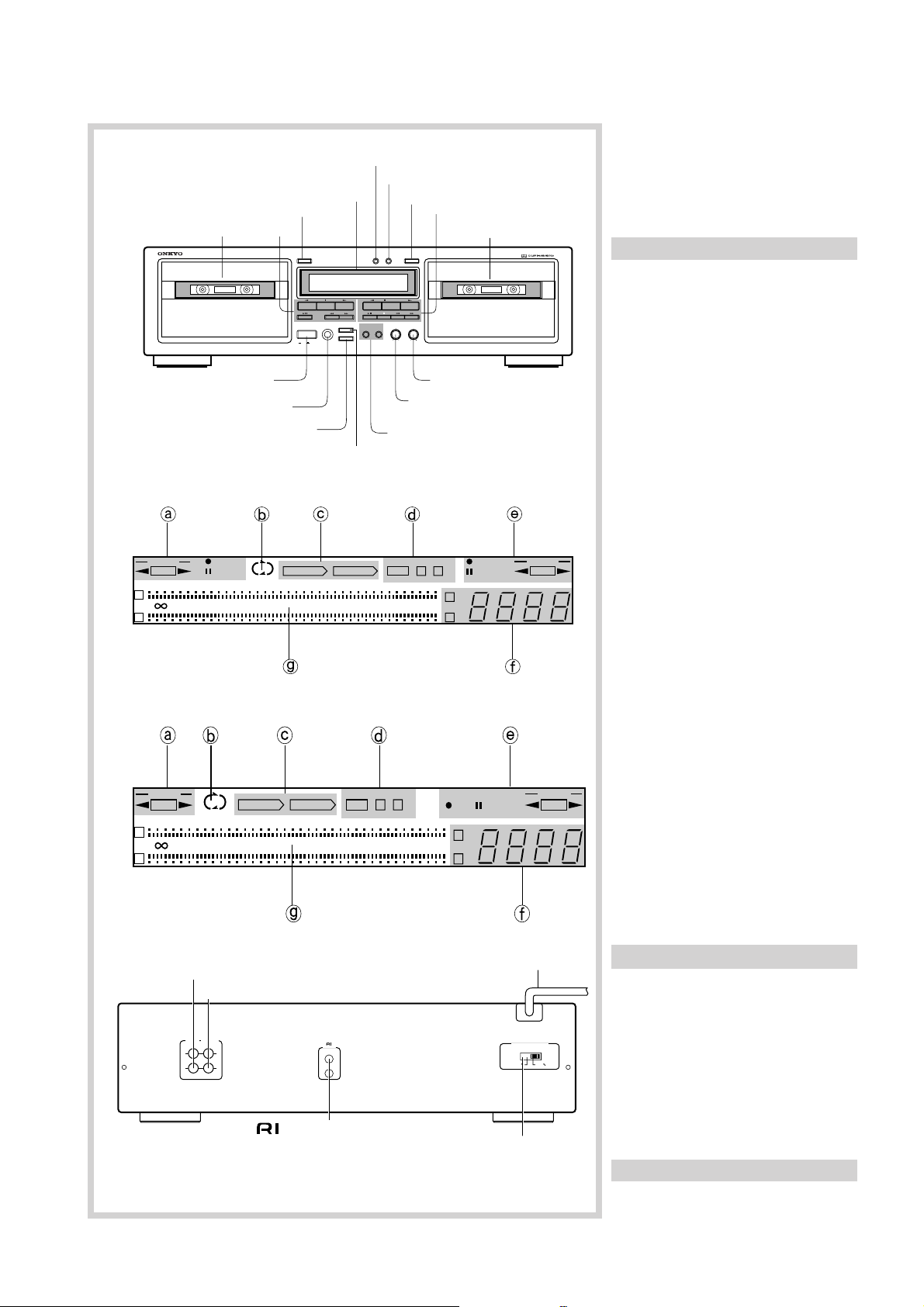
Front panel
1. Deck A cassette holder
2. Deck A operation buttons
a : Reverse play button [6]
e : Stop button [6,9]
s : Forward play button
[6,9,10,11]
t : Rec/pause button [9,10,11]
(TA-RW544 only)
d: Rewind button [7]
f: Fast forward button [7]
3. Deck A EJECT button [6,8]
4. Display
5. DECK A/B counter button
[9,10,11]
6. Counter RESET button [9,10,11]
7. Deck B EJECT button [6,8]
8. Deck B operation buttons
a : Reverse play button [6]
e DUBB.STOP : Stop button
(Dubbing stop) [7,9,12]
s : Forward play button
[6,9,10]
t : Rec/pause button [9,10,12]
; : Auto space button [13]
d: Rewind button [7]
f: Fast forward button [7]
9. Deck B cassette holder
10. REC LEVEL control knob
[9,10,11]
11. REC BALANCE control knob
[9,10,11] (TA-RW544 only)
12. DUBBING buttons (NORMAL/
HIGH) [12]
13. REVERSE MODE button
[6,8,12,15]
14. DOLBY NR button [6,8]
15. PHONES (Headphones) jack [7]
16. POWER button [5]
1. LINE IN
2. LINE OUT
5
Display
a Deck A operation and direction
indicators
b Reverse mode indicator
LINE IN LINE OUT
(REC) (PLAY)
LL
RR
REMOTE
CONTROL
VOLTAGE SELECTOR
220V-230V 120V
c Dubbing indicators
d Dolby NR indicators
e Deck B operation and direction
indicators
f Electric counter
4. REMOTE CONTROL
g Peak level indicator
3. VOLTAGE SELECTOR
Rear panel
1. Line in jacks [5]
2. Line out jacks [5]
3. Voltage selector [5] (Worldwide
model only)
4
4. Remote control jacks [14]
5. AC power cord [5]
Page 5
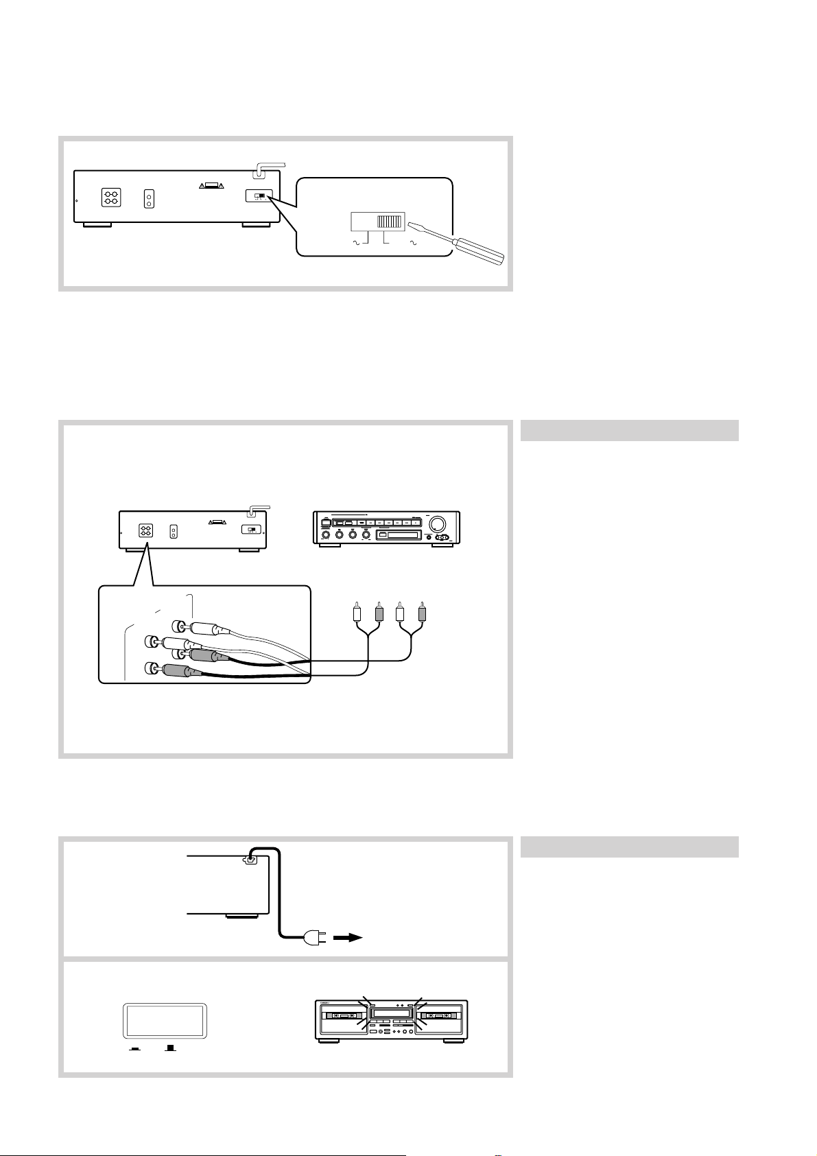
Setting the Voltage Selector (Worldwide Model Only)
Models without a voltage selector can only be used in areas where the power supply is the same as that of the cassette deck.
1. Determine the proper voltage for your
area: 220-230 V or 120 V.
C A U T I O N
RISK OF ELECTRIC SHOCK
DO NOT OPEN
220V-230V 120V
VOLTAGE SELECTOR
2. If the preset voltage does not conform
to your area, insert a screwdriver into
the groove in the switch. Slide the
switch all the way to the right (120 V)
220V-230V 120V
or to the left (220-230 V), whichever is
appropriate.
System Connections
• Do not plug in the AC power cord until all other connections have been made.
• On each pair of input or output jacks, the lower jack (marked R) corresponds to the right channel, and the upper jack (marked L) to
the left channel. Refer to the amplifier’s instruction manual for further information on connections.
Connecting to an amplifier
Connect the tape deck LINE IN jacks to the
TAPE REC jacks on the rear panel of the
amplifier and the tape deck LINE OUT
jacks to the amplifier TAPE PLAY jacks.
C A U T I O N
RISK OF ELECTRIC SHOCK
DO NOT OPEN
220V-230V 120V
••- -•
Refer to the amplifier’s instruction manual
for further information on connections.
LLRR
LINE IN LINE OUT
(REC) (PLAY)
L
R
Power Connections
1
TAPE
(REC) (PLAY)
To a wall outlet
Switching power on
1. Plug the AC power cord into a
wall outlet.
2. Press the POWER button.
The display will light.
2
POWER
ON
OFF
5
Page 6
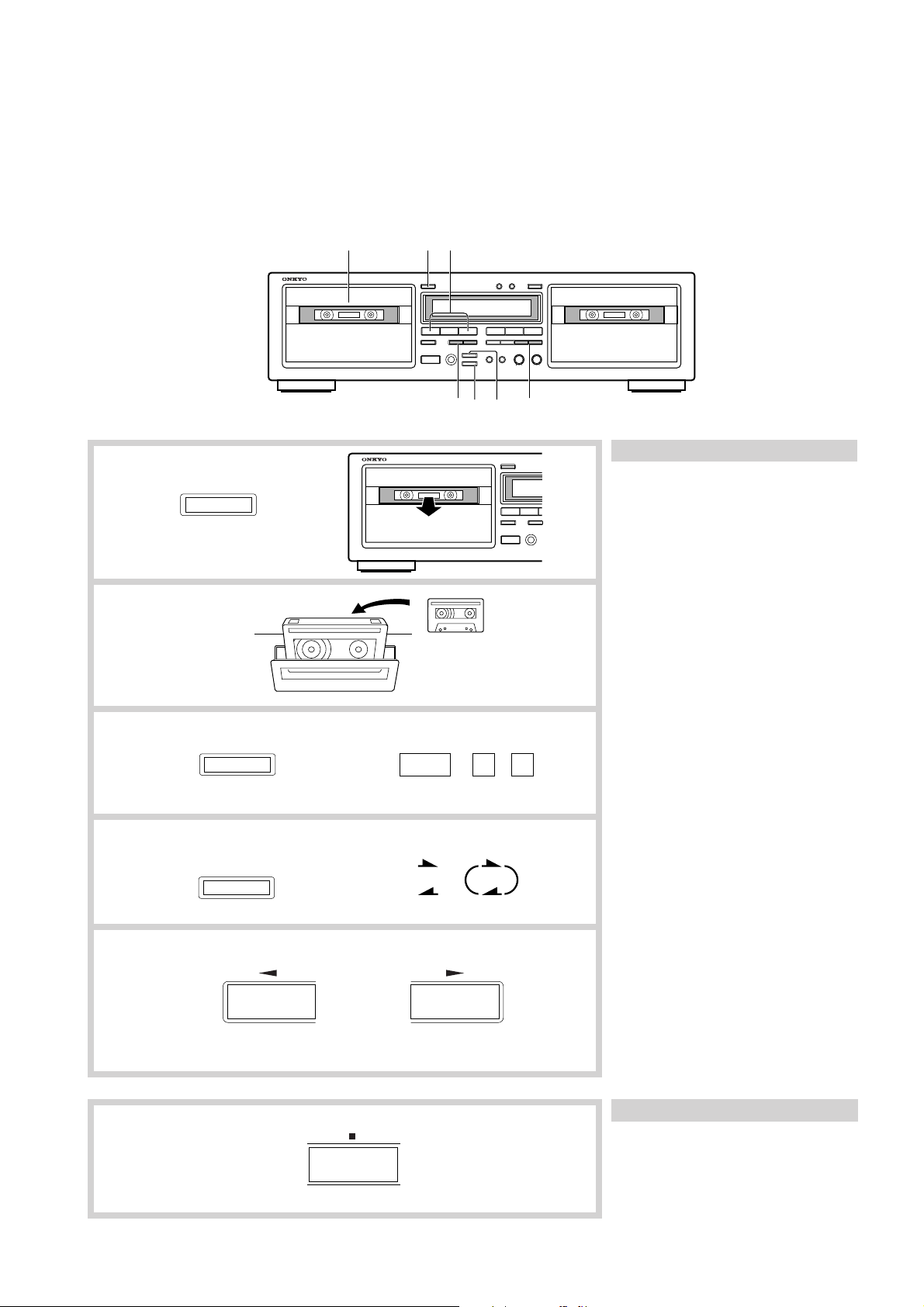
To Play a Tape
• Check once again that all connections have been completed exactly as indicated in the connections diagram and then plug in the AC
power cord.
• After turning the power on, the display illuminates and the g PAUSE indicator flashes (about 5 seconds). While the indicator is
flashing, no operation can be performed.
• This deck holds two cassettes at once. Both Deck A and Deck B are capable of auto-reverse playback.
• Tapes can be played back using either Deck A or Deck B. Follow the procedure on Deck A or B. (Deck A is pictured.)
215
34d,f(DECK A) d,f(DECK B)
Listening to a tape
1
2
3
4
5
EJECT
DOLBY NR
REVERSE MODE
DOLBY NR
OFF B C
1. Press the EJECT button to open
the cassette holder.
2. Insert a cassette.
• The side of the cassette with the
exposed tape should be facing downward.
3. Set the Dolby NR by pressing
the DOLBY NR button repeatedly until the proper Dolby NR
indicator (OFF, B or C) turns on.
• Select the same noise reduction system
that was used when the cassette was
recorded. For instance, tapes recorded
using Dolby B NR should be played
back with Dolby B NR.
4. Set the Reverse Mode by pressing the REVERSE MODE button
repeatedly until the desired
mode is displayed.
v ) one side: Only one side of the
(
tape is played back.
( b ) repeat: Both sides of the tape are
played back repeatedly eight
times or until the e button is
pressed.
5. Start playback.
• Press the a or s button depending
on which side of the cassette you wish
to listen to.
s : Playback starts from the front
side.
a : Playback starts from the reverse
side.
• The auto-stop mechanism will automatically stop the tape (depending on
the tape transport mode) if a tape is
played through to the end.
Stopping playback
Press the e button.
6
Page 7

f
d
Recheck the tape direction settings (shown
by the Deck A and Deck B direction
indicators) before pressing the d or
A
A
f button.
The following explanation assumes that the
tape direction is forward ( s ).
Fast forward and rewind
Make sure the tape is stopped before using
A
A
the fast forward or rewind function.
To fast forward the tape, press the f
button.
To rewind the tape, press the d button.
• To stop either fast forward or rewind,
press the e button.
Listening with the headphones
Plug the headphones to the PHONES jack.
EJECT
DECK A/B RE
Automatic tape selection system
DU
//
REVERSE MODE
POWER
PHONES
OFF
ON
DOLBY NR
DUBBING
NORMAL HIGH
This deck detects the type of cassette in the
cassette holder and automatically sets the
bias and equalization to the correct settings.
Tape selection is performed by detecting
the presence or absence of identification
pits on the back of the cassette shell.
Cassettes manufactured before this
identification system was adopted and
bargain cassettes that do not incorporate
these pits cannot be used with this deck.
Useful Functions Available during Playback (TA-RW544 Only)
Skipping to a song
f
d
A
4 5 6
f ff
DECK-B
A
1 4
2 3
d dd d
DECK-B
Make sure the tape is playing before using
this function.
To skip ahead to the next song,
press the f button.
It is possible to skip up to 15 songs at one
time. The number of songs skipped is
indicated by the display (P1, P2 ..... P15).
Skipping to the beginning of the
current song or a preceding song
Make sure the tape is playing before using
this function.
To skip back to the beginning of the
song being played or preceding
song, press the d button.
The number of songs skipped is indicated
by the display (–P1, –P2 ..... –P15).
Note:
The Skip function operates by detecting the
blank space between songs. Therefore, it
may not operate properly under circumstances such as the following:
1) The blank space is too short.
2) The song is interrupted by narration,
etc.
3) The music level changes, such as a
quiet section immediately followed by
a loud section.
4) There is excessive noise between songs.
7
Page 8

Recording
With TA-RW544, both Deck A and Deck B can be used for recording. Three recording methods are possible.
(A) Recording on a single cassette using Deck A or Deck B
(B) Recording the same program simultaneously on cassettes in both Deck A and Deck B
(C) Recording on two cassettes consecutively using first Deck A then Deck B
• With TA-RW344, only Deck B is available for recording.
• Check to see if one or both of the cassette’s erasure prevention tabs have been removed.
• Confirm that the cassette deck is properly connected to the amplifier.
• Illustrations enclosed in solid boxes
indicate source component operations.
1
2
3
4
DOLBY NR
1
34
DOLBY NR
OFF B C
1
Preparing for recording
Confirm that the amplifier is set up
correctly for recording. (Refer to the
amplifier’s instruction manual for details.)
1. Insert the cassettes.
Make sure the side to be recorded is
facing outward.
• Recording is not possible on the tape
leaders (the transparent sections you
see at both ends of the tape).
2. Prepare the source component to
be used for the recording.
• Tune in the desired station on the tuner.
• Load a CD (or LP) into the CD player
(or turntable).
• Load a cassette into the tape player
(analog or DAT).
3. Set the Dolby NR by pressing
the DOLBY NR button repeatedly until the desired Dolby NR
indicator (OFF, B or C) turns on.
4. Set the Reverse Mode by pressing the REVERSE MODE button
repeatedly until the desired
mode is displayed.
v ) one side: Only one side of the
(
tape is recorded.
( b ) repeat: Both sides of the tape are
recorded.
• When recording from a source component to Deck A and Deck B consecutively, select the “
b ” mode.
REVERSE MODE
Note:
This deck will not begin recording if you
press the t and s or a button at the
same time. To begin recording, first press
the t button to put the deck into the rec/
pause mode, then press either the s or a
button as appropriate.
8
Page 9

(A) Recording on a single cassette using Deck A or Deck B
2 7
2
DECK A/B RESET
3
4
t
5
REC BALANCE REC LEVEL
L R MIN
(TA-RW544 only)
6
7
e DUBB. STOP
MAX
eDUBB. STOP
s
DECK-A
L
-20 -10 -6 -3
-
dB
R
e
45
B
B
REC
PAUSE
0
DOLBY NR
+3 +6
s
DECK-B
DECK-B
t
The following explanation assumes that
Deck B is being used.
Procedure for recording
1. Prepare for recording.
(See page 8.)
Note:
With TA-RW544, when recording to
Deck A only, do not insert a cassette in
Deck B. In the “ b ” mode, recording
in Deck B may start consecutively.
2. Press the DECK A/B button to
select the appropriate Deck A or
B, and press the RESET button
to return the tape counter to
[0000].
3. Begin playing the source component.
4. Press the t button.
5. While observing the peak level
indicators, adjust the recording
level and balance.
• Use the REC LEVEL knob to adjust the
recording level.
• With TA-RW544, adjust the REC
BALANCE knob so that the left and
right channels have approximately the
same levels. This knob is normally at
DECK-B
REC
C
PAUSE
B
the center position.
• When using metal cassettes, the REC
LEVEL knob should be adjusted so that
+3 dB indicators light periodically.
When using other kinds of tapes, the 0
dB indicator should light periodically.
(See “Making Good Sound Recordings” on page 13.)
6. Put the source component into
recording standby status.
• Temporarily stop CD (or LP) play.
• Rewind the tape to the portion you wish
to start playback.
7. Press the s button on this unit
and begin playing the source
component.
You can also use the CD Synchro
Recording function if this unit is
properly connected to an ONKYO
CD player bearing the z symbol.
Stopping recording
(See page 14.)
Press the e DUBB.STOP button.
Interrupting recording briefly
Press the t button.
9
Page 10

(B) Recording the same program simultaneously on cassettes in both Deck A and Deck B (TA-RW544
only)
27
45
2
DECK A/B RESET
DECK A/B RESET
3
4
t
t
5
REC BALANCE REC LEVEL
L R MIN
MAX
DECK-A
L
-20 -10 -6 -3
-
dB
R
DECK-A
L
-20 -10 -6 -3
-
dB
R
s
REC
PAUSE
REC
PAUSE
Procedure for recording
A
1. Prepare for recording.
(See page 8.)
2. Press the RESET button to return
the tape counter for both Deck A
B
and Deck B to [0000].
• To change the active deck, press the
DECK A/B button.
3. Begin playing the source component.
4. Press the Deck A and Deck B
t buttons.
5. While observing the peak level
indicators, adjust the recording
DOLBY NR
C
+3 +6
0
B
REC
PAUSE
DECK-B
level and balance.
• Use the REC LEVEL knob to adjust the
recording level.
• Adjust the REC BALANCE knob so
that the left and right channels have
approximately the same levels. This
knob is normally at the center position.
6. Put the source component into
recording standby status.
7. Press the Deck A or Deck B s
DOLBY NR
C
+3 +6
0
B
REC
PAUSE
DECK-B
button and begin playing the
source component.
You can also use the CD Synchro
Recording function if this unit is
properly connected to an ONKYO
CD player bearing the z symbol.
(See page 14.)
10
6
7
e
DUBB. STOP
e
or
Notes:
• The following buttons and knob affect
both Deck A and Deck B.
— The REVERSE MODE button
— The DOLBY NR button
— The REC LEVEL knob and REC
BALANCE knob
• The auto space function operates both
s
Deck A and Deck B at the same time.
And, pressing the a , s or t
button on either Deck A or Deck B
affects both Deck A and Deck B.
Stopping recording
e
To stop recording on Deck A or Deck B
only, press the appropriate deck e button.
Page 11

(C) Recording on two cassettes consecutively using first Deck A then Deck B (TA-RW544 only)
2
e
DUBB. STOP
DECK A/B RESET
3
DECK A/B RESET
4
5
t
6
REC BALANCE REC LEVEL
L R MIN
MAX
s
DECK-A
L
-20 -10 -6 -3
-
dB
R
s
REC
PAUSE
DECK-B
A
B
DECK-A
0
3
8
5
REC
PAUSE
DOLBY NR DECK-B
C
+3 +6
B
2
6
Procedure for recording
1. Prepare for recording.
(See page 8.)
Note:
Be sure to set the reverse mode to
“ b ” mode.
2. Check that the Deck B direction
indicator is forward ( s ).
• To change the setting of the direction
indicator, press the s button followed
by the e DUBB.STOP button.
3. Press the RESET button to return
the tape counter for both Deck A
and Deck B to [0000].
• To change the active deck, press the
DECK A/B button.
4. Begin playing the source component.
5. Press the Deck A t button.
6. While observing the peak level
indicators, adjust the recording
level and balance.
• Use the REC LEVEL knob to adjust the
recording level.
• Adjust the REC BALANCE knob so
that the left and right channels have
approximately the same levels. This
knob is normally at the center position.
7. Put the source component into
recording standby status.
8. Press the Deck A s button and
begin playing the source component.
You can also use the CD Synchro
Recording function if this unit is
properly connected to an ONKYO
CD player bearing the z symbol.
(See page 14.)
7
8
e
s
Note:
If one of the erasure prevention tabs of the
cassettes inserted into Deck A and Deck B
has been removed, recording will stop on
that side. For example, the broken tab on
the reverse side of the cassette inserted into
Deck A will cease reverse side recording on
Deck A and both sides recording on Deck
B.
11
Page 12

Tape Dubbing
• The recording level will be fairly close to that of the tape in Deck A.
• The Dolby NR System of Deck A is automatically used to record the tape in Deck B. If you wish to monitor the signal from a Dolby
NR encoded tape during normal-speed dubbing, be sure to set the Dolby NR to match the type of Dolby NR with which the cassette
was recorded.
• During high-speed dubbing, decrease the sound level from the amplifier (or receiver) using the volume control and unplug the
headphones from the headphone jack.
1
2
3
4
REVERSE MODE
DECK-A
PLAY
DUBBING
NORMAL HIGH
12
4
DECK-B
PLAY
HIGH
NORMAL
HI-SPEED
DUBBING
DUBBING
1
Tape dubbing
1. Insert the prerecorded cassette
into Deck A , and insert the
cassette to be recorded into Deck
B.
2. Set the Reverse Mode by pressing the REVERSE MODE button
repeatedly until the desired
mode is displayed.
v ) one side: Only one side of the
(
tape is copied.
b ) repeat: Both sides of the tape are
(
copied.
3. Check the Deck A and Deck B
direction indicators to ensure
that the tape transport will start
in the desired direction.
• To dub an entire tape, be sure to select
the forward (
Decks.
To change the setting of the direction
indicator, press the a or s button,
then the e button
4. Begin dubbing by pressing the
NORMAL or HIGH button.
[NORMAL] : Normal-speed dubbing
[HIGH] : High-speed dubbing about
s ) direction on both
will begin.
12
DUBB. STOP
t
half the time normally required
will begin.
Stopping dubbing
Press the Deck B e DUBB.STOP
button.
Briefly interrupting dubbing
Press the t button. (Deck B)
In this case, you can change the cassette in
Deck A or search the desired portion by
using the buttons for Deck A. To resume
dubbing, press the NORMAL or HIGH
button again.
Page 13

Useful Recording Functions
a , s (Deck A)
a , s (Deck B)
t
;
Inserting blank spaces between
songs when editing tapes
1. Press the
or s button to begin recording.
2. Press ; button at any point
during recording where you want
to enter a blank space about five
seconds long.
• The
• After the blank space has been inserted,
the tape stops automatically and the
deck returns to the rec/pause mode.
3. To continue recording, press the
a or s button.
• The ; button works in both the record
and rec/pause modes.
To insert a blank space of less
than five seconds between songs
Press the t button to return to the rec/
pause mode or press the a or s button
before a five-second period has elapsed.
tt
t button and the a
tt
indicator flashs on and off.
PLAY
To insert a blank space of more
than five seconds between songs
Hold the ; button down for as long as you
want the blank space to be. The deck will
return to the rec/pause mode immediately
when the button is released.
Pressing the
;
dubbing
Pressing the ; button during dubbing
causes Deck A to stop while a blank space
is inserted on the tape in Deck B. Then
Deck B reverts to the dubbing pause mode.
To continue dubbing, press the NORMAL
or HIGH button.
Making Good Sound Recordings
Dolby Noise Reduction System
Dolby B NR is the system used in most cassette tape decks to
reduce the background noise that is inherent in all cassette tapes.
This deck also features Dolby C NR, an even more effective
noise reduction system, developed by Dolby Laboratories in
response to the demand for even better sound from cassette tapes.
The Dolby HX Pro System
Tape sensitivity is constantly changing as recordings are made
due to the biasing effect of high frequency audio signals. Dolby
HX Pro is a system that compensates for these undesirable
fluctuations during recording. It does not operate during playback, so cassettes recorded with Dolby HX Pro can be played
back on decks not equipped with the system.
Note:
Dolby HX Pro operates independently of Dolby B and C NR, and
only during recording.
Setting the Proper Recording Level
The recording level has an important effect on the sound quality a
tape will have when it is played back. A recording level that is
too high will cause distortion while one which is too low will
lower the signal-to-noise ratio resulting in a tape with excessive
“hiss noise.” It is particularly important to set the recording level
correctly with cassette tapes since they have a much thinner
magnetic coating than open reel tapes. The thin coating gives the
tape a comparatively low saturation level which can easily be
surpassed if the recording level is set too high.
The optimal recording level varies depending on the type of the
tape being used. With this tapedeck, adjust the REC LEVEL knob
so the PEAK LEVEL indicator occasionally hits the “+6dB” line
with “Metal” tapes and “+4dB” line with “Normal” or “High”
position tapes, respectively. It should be noted that the peak level
may change from one track to another on some recording sources.
The recording level indicators feature a peak-hold function for the
indicators from –6 dB through +6 dB. This can come in handy
when setting the recording level.
;;
; button during
;;
13
Page 14

Connecting ONKYO Components for z
Operation
If this unit is properly connected to another ONKYO component bearing the z symbol, you will be able to control it using the other
component’s remote control.
For remote control operation
The upper and lower remote control jacks
Tuner
CD player
1234567890+10
6 DISC
Main amplifier
Pre amplifier
have the same function.
For remote control operation, connect this
jack to any ONKYO amplifier, receiver or
CD player that are equipped with a z
remote control jack using the remote
control cable.
Note:
Do not attempt to connect the z remote
control jack to any equipment other than an
ONKYO component that are equipped with
a z remote control jack. Doing so could
cause the unit to malfunction.
The function listed below can be accomplished using the remote control of the
master unit.
s a : Play
d : Rewind
f : Fast forward
e : Stop
t : Rec/Pause
TA-RW544
TA-RW344
CD synchro recording system
Once connections are made, as shown left,
this function becomes enabled. It automatically starts recording on the cassette deck
when the s button of the CD player is
pressed. (See below.)
CD Synchro Recording System
Once the TA-RW544/344 is connected to a CD player bearing the z symbol (see above), pressing the s button of the CD player will
cause recording to begin automatically on the TA-RW544/344. Three recording methods are possible. (See pages 8 - 11.)
1. Prepare for recording.
(See pages 8 - 11.)
2
2. Start the CD player.
s
Recording will begin simultaneously.
Note:
Even if the CD player is stopped during
recording, the cassette deck will continue
recording. In this case, make sure to press
the e button on the cassette deck.
14
Page 15

Reverse Mode Function
• Recheck the tape travel direction settings (shown by the Deck A and Deck B direction indicators) before beginning playback or
recording.
• The following explanation assumes that cassette side A is facing outward.
• There is a silent gap about ten seconds long when the direction of tape travel switches from forward to reverse or from reverse to
forward when the end of a tape side is reached.
Reverse mode
PlaybackRecording
Deck A or Deck B
Deck A and Deck B
Direction Playback / Recording sequence Explanation
s
a
s
A
B
A → B → A → B ⋅⋅⋅⋅ → A →
Press the s button. Playback will begin and
end on side A (front).
Press the a button. Playback will begin and
end on side B (rear).
Press the s button. Playback will begin
from side A and continue to side B. When the
end of side B is reached, the playback begin
again from side A . This sequence will repeat
eight times.
B
Press the a button. Playback will begin
from side B and continue to side A. When the
a
s
a
s
B → A → B → A ⋅⋅⋅⋅ → B →
A
A → B → A → B ⋅⋅⋅⋅ → A →
Deck A Deck B Deck B
B
One cycle
B → A → B → A ⋅⋅⋅⋅ → B →
Deck A Deck B Deck A Deck B Deck A
A
One cycle
A
end of side A is reached, the playback begin
again from side B. This sequence will repeat
eight times.
If there are tapes in both Deck A and Deck B,
playback will begin from side A of the tape in
Deck A. When the end of side B is reached,
Deck B will begin playback. This sequence
will repeat four times.
Press the t button then the s button.
Recording will begin from and end on side A
(front).
Press the t button then the a button.
a
s
a
s
Deck A
Deck A and Deck B
(TA-RW544 only)
* You can simultaneously record on tapes in Deck A and Deck B except during continuous recording.
a
Deck A
B
A → B
B
A → B → A → B
Deck A
Deck B
B → A → B
Deck BDeck A
Recording will begin and end on side B
(rear).
Press the t button then the s button.
Recording will begin from side A and
continue to side B. When the end of side B is
reached, recording will stop automatically.
If you begin recording in the reverse
direction, recording will begin from side B of
the tape. When the end of side B is reached,
recording will stop automatically.
Continuous recording
Before performing continuous recording, set
the direction of the tape in Deck B.
Press the Deck A t button then the s (or
a ) button. Recording will begin from side
A (B) of the tape in Deck A. As soon as the
recording on side B of the tape in Deck A is
complete, recording on Deck B will begin.
15
Page 16

Handling Cassette Tapes
Examine cassette tapes carefully before using them with the TA-RW411.
AB
A
1. 2.
A
High position
detection hole
Erasure prevention
Cassette tapes are constructed with erasure
prevention tabs to prevent accidental
erasure of the tape.
1 If you wish to protect a recording from
accidental erasure, break off the tab(s)
on the appropriate side(s). It will no
longer be possible to use the recording
button with such a cassette.
2 If at some later date you wish to record
the cassette, simply cover the hole(s)
with small pieces of cellophane tape.
• Be sure not to cover the holes for
detecting high-position tapes.
Loose tape
Loose tape can cause tangling around the
pinch roller and capstan and jam the
mechanism.
Remove any tape slack with a pencil or
similar device as shown in the diagram.
Tapes not recommended
1. C-120 tapes
C-120 tape is thin and therefore easily
broken. There is a possibility that tape
could get caught on the pinch roller or
capstan.
2. Endless tapes
Do not use endless tapes.
A
A
No! No!
No! No!
Tape storage
• Do not touch the tape surface.
• Do not put thick paper or cardboard
labels in the cassette holder.
• Do not put tapes near magnetic sources
(speakers, amplifiers, TVs, etc.) Your
important recording might be erased or
damaged.
• Do not expose cassettes to direct
sunlight.
Recommended tapes
Normal position
Maxell UDI
Maxell UDII
Metal positionHigh position
Maxell XS
16
Page 17

Cassette Deck Maintenance
Erase head
REC/PB head
Pinch rollers
This deck requires no lubrication.
Head, Pinch Roller and Capstan Cleaning
Playback sound quality can be greatly diminished if magnetic
particles are allowed to accumulate on the recording/playback
head or playback head. Be sure to clean the head periodically,
normally 2 - 3 times a month, to maintain your deck’s original
performance. Dirty heads may cause:
• Poor sound quality (lose of high frequency response)
• Decreased volume
• Skipping
• Incomplete erasure of previous recordings
If the pinch rollers and capstan are dirty, the tape may become
tangled and damaged by wrapping around the pinch roller and
capstan.
To prevent these problems, clean the heads, pinch rollers and
capstans with a cotton swab dipped in cleaning fluid.
Capstans
Demagnetizing
Residual magnetism builds up in the heads after the cassette deck
has been used for an extended period of time. This buildup
introduces noise and static into tapes and impairs high frequency
response. To prevent this, demagnetize the heads with any
commercially available head eraser once every 50 hours of use.
Refer to the instruction manual of the head eraser for detailed
instructions.
17
Page 18

Specifications
TA-RW544
Track Format: 4-track, 2-channels
Erasure System: AC erase
Tape Speed: 4.8 cm/sec. (1-7/8 i.p.s.)
9.6 cm/sec. (3-3/4 i.p.s.) (high speed
dubbing)
Wow and Flutter: 0.07 % (WRMS)
Frequency Response: 20 — 15,000 Hz (Normal)
(30 — 14,000 Hz ± 3 dB)
20 — 16,000 Hz (High)
(30 — 15,000 Hz ± 3 dB)
20 — 17,000 Hz (Metal)
(30 — 16,000 Hz ± 3 dB)
S/N Ratio: Dolby NR off: 58 dB (metal position
tape)
A noise reduction of 10 dB above
5 kHz and 5 dB at 1 kHz is possible
with Dolby B NR.
A noise reduction of 20 dB at 5 kHz
is possible with Dolby C NR.
Input Jacks: Line IN: 2
Input sensitivity: 80 mV
Input impedance: 40 kohms
Outputs: Line OUT: 2
Standard output level: 500 mV
(0 dB)
Optimum load impedance: over
50 kohm
Headphone jack: 1
Optimum load impedance:
8 to 200 ohms
Motors: DC servo motor × 2, DC motor × 2
Heads: REC/PB: 2
ERASE: 2
Power Supply: European and Australian models:
AC 230V, 50 Hz
U.S.A. and Canadian models:
AC 120V, 60 Hz
Worldwide model:
AC 120V and AC 220-230V,
Switchable 50/60 Hz
Power Consumption: 31 watts
Dimensions: 435(W) × 121(H) × 305(D) mm
(17-1/8" × 4-3/4" × 12")
Weight: 5.9 kg. (13.0 lbs.)
TA-RW344
Track Format: 4-track, 2-channels
Erasure System: AC erase
Tape Speed: 4.8 cm/sec. (1-7/8 i.p.s.)
9.6 cm/sec. (3-3/4 i.p.s.) (high-speed
dubbing)
Wow and Flutter: 0.07 % (WRMS)
Frequency Response: 20 — 15,000 Hz (Normal)
(30 — 14,000 Hz ± 3 dB)
20 — 16,000 Hz (High)
(30 — 15,000 Hz ± 3 dB)
20 — 17,000 Hz (Metal)
(30 — 16,000 Hz ± 3 dB)
S/N Ratio: Dolby NR off: 58 dB (metal position
tape)
A noise reduction of 10 dB above
5 kHz and 5 dB at 1 kHz is possible
with Dolby B NR.
A noise reduction of 20 dB at 5 kHz
is possible with Dolby C NR.
Input Jacks: Line IN: 2
Input sensitivity: 80 mV
Input impedance: 50 kohms
Outputs: Line OUT: 2
Standard output level: 500 mV
(0 dB)
Optimum load impedance: over
50 kohms
Headphone jack: 1
Optimum load impedance:
8 to 200 ohms
Motors: DC servo motor × 2, DC motor × 2
Heads: REC/PB: 1
PB: 1
ERASE: 1
Power Supply: European and Australian models:
AC 230V, 50 Hz
U.S.A. and Canadian models:
AC 120V, 60 Hz
Worldwide model:
AC 120V and AC 220-230V,
Switchable 50/60 Hz
Power Consumption: 29 watts
Dimensions: 435(W) × 121(H) × 305(D) mm
(17-1/8" × 4-3/4" × 12")
Weight: 5.9 kg. (13.0 lbs.)
18
Specifications and external appearance are subject to change
without notice because of product improvements.
Page 19

Troubleshooting Guide
The following guide lists problems which do not require professional servicing. If, however, the problem cannot be remedied using this
guide, contact an ONKYO authorized service center for assistance.
• No power.
Cause: Power cord plug is loose
Remedy: Insert plug properly into outlet.
• Playback but no sound.
Cause: Incorrect connection.
Remedy: Check and connect correctly according to page
5.
Cause: Stereo amplifier input selector switch is set to
incorrect position.
Remedy: Change switch position.
• Tape does not move.
Cause: Slack tape wound around pinch roller.
Remedy: Take up slack with a pencil (see page 16).
• t button does not engage.
Cause: No tape in cassette holder.
Remedy: Insert cassette tape.
Cause: Erasure prevention tab(s) removed.
Remedy: Change cassette or cover tab hole with
cellophane tape.
• Hoarse sound, balance unstable.
Cause: Playback head dirty.
Remedy: Clean head (see page 17).
Cause: Tape is stretched.
Remedy: Replace cassette.
• Excessive noise and tape hiss.
Cause: Head has become magnetized.
Remedy: Demagnetize (see page 17).
Cause: Tape with high noise level.
Remedy: Replace cassette.
• Distorted sound.
Cause: Distortion in tape.
Remedy: Tape is probably bad but confirm by listening
to another.
• Recordings are distorted.
Cause: Recording was done at too high a level.
Remedy: Readjust REC LEVEL knob according to the
directions on page 9.
• Tape squeal and skipping.
Cause: Dirty heads, pinch rollers or capstan shafts.
Remedy: Clean (see page 17).
Cause: Cassette shell is binding tape or tape is stretched.
Remedy: Change cassette or try correcting with fast
forward and rewind.
• Excessive hum during playback.
Cause: Connecting cables not inserted firmly.
Remedy: Insert plugs firmly.
Cause: External flux leakage from nearby amplifier or TV
set.
Remedy: Move deck away from hum source.
• High frequencies too strong.
Cause: Dolby NR encoded tape played back with NR off.
Remedy: Select the same noise reduction (Dolby NR B
or C) used when the cassette was recorded.
Cause: Incorrect equalization.
Remedy: Confirm that cassette has tape type detection
holes.
• No high frequency sounds.
Cause: Tape not encoded with Dolby NR played back
with Dolby B or C NR on.
Remedy: Select the appropriate NR mode using the
DOLBY NR button (OFF).
Cause: Heads have become dirty.
Remedy: Clean (see page 17).
• The skip function does not operate properly (TARW544 only).
Cause: The silent sections between songs are too short or
noisy.
Remedy: Use a cassette with sufficient silent sections of
sufficient length between songs.
• Deck does not operate properly.
Cause: Tape transport control microcomputer has been
exposed to interference from power supply or static
electricity.
Remedy: Press the POWER button to turn off the
power. Wait approximately 10 seconds
and turn it on again.
19
Page 20

Sales Planning & Promotion Dept.: 2-1, Nisshin-cho, Neyagawa-shi, OSAKA 572, JAPAN
http://www.onkyo.co.jp/
HOMEPAGE
Tel: 0720-31-8111 Fax: 0720-33-5222
ONKYO U.S.A. CORPORATION
200 Williams Drive, Ramsey, N.J. 07446, U.S.A.
Tel: 201-825-7950 Fax: 201-825-8150 E-mail: onkyo@onkyousa. com
ONKYO EUROPE ELECTRONICS GmbH
Industriestrasse 18-20, 82110 Germering, GERMANY
Tel: 089 84 93 20 Fax: 089 84 93 226
ONKYO FRANCE
Immeuble Le Diamant, Domaine Technologique de Saclay, 4 Rue René Razel,
91892 SACLAY, FRANCE Tel: (1) 69 33 14 00 Fax: (1) 69 41 35 84
SN29342382Y
2
E
 Loading...