

Page 1

TA-6711
Stereo Cassette Tape Deck
REC LEVEL
5
EJECT
TIMER
OFF
REC PLAY
POWER
ON OFF
3 HEAD DUAL CAPSTAN
DIMMER ELAP/REMA RESET T- SIZE MPX FILTER DOLBY NR AUTO ACCUBIAS
REW FF REC PAUSE STOP PLAY
L MIC R
MONO
4 6
3 7
2 8
1 9
TAPE MONITOR
0 10
ACCUBIAS REC BALANCE
STEREO CASSETTE TAPE DECK TA- 6711
L R
Instruction Manual
CONTENTS
Features................................................ 2
Important Safeguards........................... 3
Precautions .......................................... 3
Control Position and Names ................ 4
System Connections ............................ 5
Power Connections .............................. 5
Playing Tapes ...................................... 6
Real Time Counter............................... 8
Recording .......................................... 10
Useful Functions................................ 13
Handling Cassette Tape ..................... 14
Troubleshooting Guide ...................... 15
Cassette Deck Maintenance............... 16
Specifications .................................... 16
1
Page 2
Thank you for your purchase of the Onkyo
TA-6711 cassette tape deck. Please read this manual thoroughly before making connections and turning power on.
Follow these instructions to obtain optimum performance and
maximum listening enjoyment from your new TA-6711.
Please retain this manual for future reference.
Features
Fullauto Accubias Control System (Bias &
Level) & Manualbias Control System
Re-inforced Cassette Holder
3-Motor, 3-Head, Dual capstan Silent Deck
Mechanism
Dolby HX Pro, B/C noise reduction
PC-OCC Wire Head Windings
Pure, single-crystal, oxygen-free copper head windings
prevent signal loss for faithful high-frequency recording.
Full-logic controls
Quiet and fast, they let you switch directly between any two
transport modes without having to press the stop button.
One-touch CD synchronized recording
zz
z System compatible
zz
This means you can contorl virtually all of the casette deck's
major functions with other ONKYO remote controls.
FOR CANADIAN MODEL:(POUR LE MODELE
CANADIEN:)
• For models having a power cord with a polarized plug
CAUTION:
TO PREVENT ELECTRIC SHOCK, MATCH WIDE BLADE
OF PLUG TO WIDE SLOT, FULLY INSERT.
• Sur les modèles don't la fiche est polarisée
ATTENTION:
POUR EVITER LES CHOCS ELECTRIQUES, INTRODUIRE
LA LAME LA PLUS LARGE DE LA FICHE DANS LA
BORNE CORRESPONDANTE DE LA PRISE ET POUSSER
JUSQ'AU FOND.
ATTENTION FOR BRITISH MODEL:
Replacement and mounting of an AC plug on the power supply
cord of this unit should be performed only by qualified service
personnel.
IMPORTANT: The wires in the mains lead are coloured in
accordance with the following code:
Blue: Neutral
Brown: Live
As the colours of the wires in the mains lead of this unit may not
correspond with the coloured markings identifying the terminals
in your plug, proceed as follows:
The wire which is coloured blue must be connected to the
terminal which is marked with the letter N or coloured black.
The wire which is coloured brown must be connected to the
terminal which is marked with the letter L or coloured red.
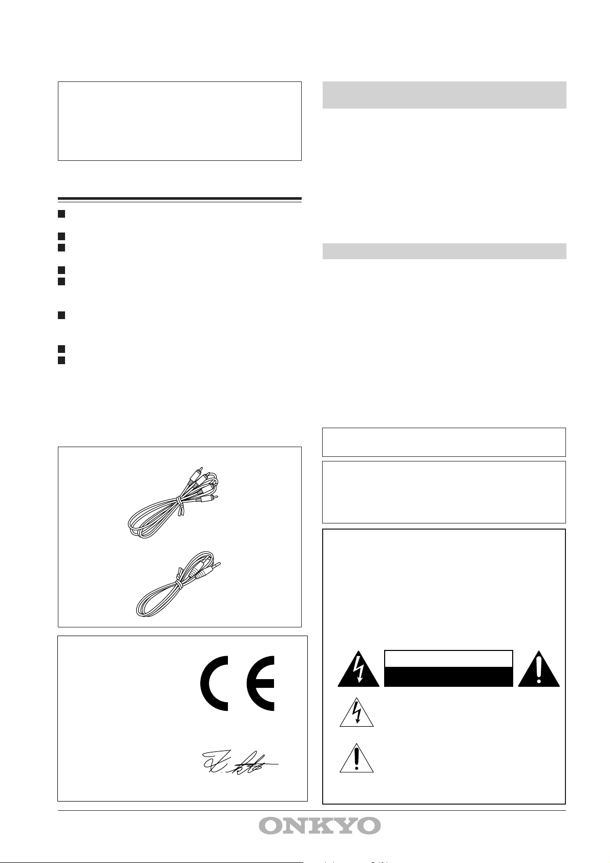
Supplied accessories
2 Audio connection cable
1 Remote control cable
Declaration of Conformity
We,
ONKYO EUROPE
ELECTRONICS GMBH
INDUSTRIESTRASSE 18/20
82110 GERMERING,
GERMANY
declare in own responsibility, that the ONKYO product described
in this instruction manual is in compliance with the corresponding
technical standards such as EN55013,EN55020,EN60555-2,
EN60065
GERMERING,GERMANY
K. KOBAYASHI
ONKYO EUROPE ELECTRONICS GMBH
This apparatus complies with the requirements of EC directive
87/308/EEC.
Dolby noise reduction and HX Pro headroom extension
manufactured under license from Dolby Laboratories Licensing Corporation. HX Pro originated by Bang and Olufsen.
"Dolby,'' the double-D symbol and "HX Pro'' are trademarks
of Dolby Laboratories Licensing Corporation.
WARNING
"TO REDUCE THE RISK OF FIRE OR ELECTRIC
SHOCK, DO NOT EXPOSE THIS APPLIANCE TO RAIN
OR MOISTURE.''
CAUTION
"TO REDUCE THE RISK OF ELECTRIC SHOCK, DO NOT
REMOVE COVER (OR BACK). NO USER-SERVICEABLE
PARTS INSIDE. REFER SERVICING TO QUALIFIED
SERVICE PERSONNEL.''
CAUTION
RISK OF ELECTRIC SHOCK
DO NOT OPEN
• The lightning flash with arrowhead symbol,
within an equilateral triangle, is intended to
alert the user to the presence of uninsulated
"dangerous voltage'' within the product's
enclosure that may be of sufficient magnitude
to constitute a risk of electric shock to
persons.
• The exclamation point within an equilateral
triangle is intended to alert the user to the
presence of important operating and
maintenance (servicing) instructions in the
literature accompanying the appliance.
2
Page 3

Important Safeguards
Precautions
1. Read Instructions — All the safety and operating instructions
should be read before the appliance is operated.
2. Retain Instructions — The safety and operating instructions
should be retained for future reference.
3. Heed Warnings — All warnings on the appliance and in the
operating instructions should be adhered to.
4. Follow Instructions — All operating and use instructions should
be followed.
5. Water and Moisture — The appliance should not be used near
water — for example, near a bathtub, washbowl, kitchen sink,
laundry tub, in a wet basement, or near a swimming pool, and the
like.
6. Carts and Stands — The appliance should be used only with a
cart or stand that is recommended by the manufacturer.
6A. — An appliance and cart combination should be moved with care.
Quick stops, excessive force, and uneven surfaces may cause the
appliance and cart combination to overturn.
7. Wall or Ceiling Mounting — The appliance should be mounted
to a wall or ceiling only as recommended by the manufacturer.
8. Ventilation — The appliance should be situated so that its
location or position does not interfere with its proper ventilation.
For example, the appliance should not be situated on a bed, sofa,
rug, or similar surface that may block the ventilation openings; or
if placed in a built-in installation, such as a book case or cabinet
that may impede the flow of air through the ventilation openings,
there should be free space of at least 20 cm (8 in.) and open up
behind the appliance.
9. Heat — The appliance should be situated away from heat sources
such as radiators, heat registers, stoves, or other appliances
(including amplifiers) that produce heat.
10. Power Sources — The appliance should be connected to a power
supply only of the type described in the operating instructions or as
marked on the appliance.
11. Polarization — If the appliace is provided with a polarized plug
having one blade wider than the other, please read the following
information: The polarization of the plug is a safety feature. The
polarized plug will only fit the outlet one way. If the plug does not
fit fully into the outlet, try reversing it. If there is still trouble, the
user should seek the services of a qualified electrician. Under no
circumstances should the user attempt to defeat the polarization of
the plug.
12. Power-Cord Protection — Power-supply cords should be routed
so that they are not likely to be walked on or pinched by items
placed upon or against them, paying particular attention to the cords
at plugs, convenience receptacles, and the point where they exit
from the appliance.
13. Cleaning — The appliance should be cleaned only as reco-
mmended by the manufacturer.
14. Nonuse Periods — The power cord of the appliance should be
unplugged from the outlet when left unused for a long period of
time.
15. Object and Liquid Entry — Care should be taken so that objects
do not fall and liquids are not spilled into the enclosure through
openings.
16. Damage Requiring Service — The appliance should be
serviced by qualified service personnel when:
A. The power-supply cord or the plug has been damaged; or
B. Objects have fallen or liquid has been spilled into the appliance;
or
C. The appliance has been exposed to rain; or
D. The appliance does not appear to operate normally or exhibits a
marked change in performance; or
E. The appliance has been dropped or the enclosure damaged.
17. Servicing — The user should not attempt to service the appliance
beyond that described in the operating instructions. All other
servicing should be referred to qualified service personnel.
PORTABLE CART WARNING
S3125A
1. Warranty Card
The serial number is written on the rear panel of this unit.
(Write the serial number and model number onto your
warranty card and keep it in a safe place.)
2. Recording Copyright
Recording of copyrighted material for other than personal use
is illegal without permission of the copyright holder.
3. Deck Location
• Do not use or leave in direct sunlight or in other places
subject to high temperature and humidity. The unit should
also not be left in potentially hot places such as near heating
appliances. Excessive heat and moisture can lead to internal
damage and serious malfunctions (this also applies to
cassette tapes). The recommended ambient temperature
range is 5°C to 35°C.
• Avoid damp and dusty places and locations prone to
vibrations.
• Be extremely careful with the recording/playback heads.
Clean and demagnetize them regularly, but under no
circumstances should magnets or other metals be used
anywhere near the heads.
• This unit is extremely sensitive to magnetic fields, so do not
use near large speakers or other devices which generate
magnetic fields.
• Hum may even be induced by magnetic flux leakage from
the power transformer in certain amplifiers. Therefore, this
unit should also be kept clear of the amplifier.
• Do not remove the cabinet case. If any of the internal parts
are handled, there is a considerable danger of electric
shock.
4. Cassettes to Avoid:
• Cassettes with poorly formed cases that rattle during rewind
and fast forward.
• Low cost cassettes with no guide roller or pressure pad
spring should never be used for stereo.
• C-120 cassettes — because the tape and the coating are
extremely thin, distortion levels are high. Also, even a
slight stretching of the tape will make it susceptible to
being caught up in the pinch roller and capstan.
• Endless tapes, if used for a long period of time, can
overheat.
5. Power
WARNING
BEFORE PLUGGING IN THE UNIT FOR THE
FIRST TIME, READ THE FOLLOWING SECTION
CAREFULLY.
• Some models are designed for use only with the power
supply voltage of the region where they are sold.
European models: AC 230V, 50Hz
U.S.A. and Canadian models: AC 120V, 60Hz
Worldwide models: AC 120 and 220-230V
switchable, 50/60Hz
• Voltage Selector (Rear Panel)
Worldwide models are equipped with a voltage selector to
conform with local power supplies. Be sure to set this
switch to match the power supply in your area before
plugging in the unit. Models without a voltage selector can
only be used in areas where the power supply voltage is the
same as that of the unit.
Voltage selector Voltage selector
220V-230V
120V
at AC120V
220V-230V
at AC220-230V
120V
3
Page 4

Control Positions and Names
If there is a protective film on the surface of
the display which makes it difficult to read,
remove it.
For more information about a button or
control, turn to the page number listed in
square brackets [ ].
1 POWER
2 EJECT
EJECT
TIMER
OFF
REC PLAY
POWER
ON OFF
3 TIMER
4
3 HEAD DUAL CAPSTAN
17 Tape operation buttons
d
f
o
g
e
s
REW
FF
REC
PAUSE
STOP
PLAY
5 DIMMER
6 ELAP/REMA
7 RESET
8 T-SIZE
9 MPXFILTER
10 DOLBY NR
11 AUTO ACCUBIAS
DIMMER ELAP/REMA RESET T- SIZE MPX FILTER DOLBY NR AUTO ACCUBIAS
REW FF REC PAUSE STOP PLAY
16 MIC
15 ACCUBIAS
14 REC BALANCE
12 TAPE MONITOR
REC LEVEL
5
4 6
3 7
2 8
1 9
TAPE MONITOR
0 10
L MIC R
MONO
ACCUBIAS REC BALANCE
STEREO CASSETTE TAPE DECK TA- 6711
L R
13 REC LEVEL
Front Panel
1. Power Switch and indicator [5]
2. Eject Button
3. Timer Switch [13]
4. Cassette Holder
5. Dimmer Button [7]
6. Elapsed/Remaining Button [8]
7. Reset Button [8]
8. Tape Size Selector Button [8]
9. Multiplex Filter Button [12]
10. DOLBY NR Button [6, 10, 12]
11. Auto Accubias Button [10, 11]
12. Tape Monitor Button and Indicator [13]
13. Recording Level Control Knob
[10]
14. Rec Balance Control Knob [10]
15. Accubias Control Knob [11]
16. Microphone Jacks [13]
17. Tape Operation Buttons
dd
d : Rewind Button [7]
dd
ff
f : Fast Forward Button [7]
ff
oo
o : Recording Button [10]
oo
gg
g : Pause Button [7]
gg
ee
e : Stop Button [7]
ee
ss
s : Play Button [6]
ss
REAL TIME COUNTER
ELAPSED REMAIN
PEAK LEVEL
BIAS
START
6
L CH
R CH
(dB)
30
20 14
7654
MPX FILTER ACCUBIAS SET
10 6 4
1 0 +1 +2 +3 +4 +5
32
2
+6 +7
OFF
DOLBY NR
4 5321
BC REC
+2 +4 +6 +100
OPERATION
Display
1. Real Time Counter/Tape Size
Indicator
2. Multiplex Filter Indicator
3. Accubias Set Indicator
4. Dolby NR Indicators
OFF : OFF
B : Dolby B NR
C : Dolby C NR
5. Tape Operation Indicators
REC : Recording Indicator
gg
g : Pause Indicator
gg
ss
s : Play Indicator
ss
6. Peak Level/Recording Bias
Indicators
4
Page 5

System Connections
• Do not plug in the power cord until all connections have been made.
• On each pair of input or output jacks, the lower jack (marked R) corresponds to the right channel, and the upper jack (marked L) to
the left channel. Also refer to the amplifier's instruction manual for further information on connections.
Connecting to an Amplifier
ONKYO
®
LINE IN LINE OUT
(REC) (PLAY)
L
R
If the TA-6711 is properly connected to another Onkyo component bearing the z mark, you will be able to control the TA-6711 using
the other component's remote control.
AVIS
WARNING
••- -•
Connect the tape deck LINE IN jacks to the
TAPE REC jacks on the rear panel of the
amplifier and the tape deck LINE OUT
jacks to the amplifier TAPE PLAY jacks.
TAPE
(REC) (PLAY)
LLRR
Also refer to the amplifier's instruction
manual for further information on connec-
tions.
For Remote Control Operation
The upper and lower remote control jacks
have the same function.
For remote control operation, connect this
jack and any Onkyo amplifier, receiver or
CD player bearing the z mark using the
remote control cable.
Note:
Do not attempt to connect the z remote
control jack to any equipment other than an
Onkyo component bearing the z mark.
Doing so could cause the unit to malfunc-
tion.
The functions listed below can be accom-
plished using the remote control of the
master unit.
s :Play
f :Fast forward
d :Rewind
e :Stop
t :Rec/pause
Power Connections
CD Synchro Recording System
Once connections are made as shown at
left, this function becomes operational. It
automatically starts recording on the
cassette deck when the s button of the
CD player is pressed. (See page 12.)
Switching Power On
1. Plug the AC power cord into a wall
outlet.
2. When you press the POWER button,
the indicator and the display will light
up.
5
Page 6

Playing Tapes
Cassette holder Dolby NREJECT
1
2
3
4
DOLBY NR
EJECT
d,f
eSTOP
gPAUSE
OFFBC
sPLAY
Listening to a Tape
1. Press the EJECT button to open
the cassette holder.
2. Insert a cassette.
• The portion of the cassette where the
tape is exposed sholud be facing
downward and the side you wish to
play facing outward.
3. Close the cassette holder.
4. Select the appropriate Dolby NR
mode using the Dolby NR button.
Each press of the Dolby NR button
advances the Dolby NR mode setting
one step through the following sequence: B, C, OFF, B, etc.
Select the B setting if the cassette to be
played was recorded using Dolby B
NR. Use the C setting if the cassette
was recorded using Dolby C NR. Tapes
recorded without Dolby NR must be
played back using the OFF setting.
5. Press the
begin playback.
The Peak Level indicators will light
during playback showing the strength of
the recorded signal.
The auto-stop mechanism will automatically stop tape transport if a tape is
played through to the end.
• The TAPE MONITOR indicator lights
when power is initially turned on. If the
s PLAY button is pressed while the
TAPE MONITOR indicator is not lit,
the indicator lights automatically.
s s
s PLAY button to
s s
Automatic Tape Selection
System
This deck automatically detects the type of
5
PLAY
REAL TIME COUNTER
ELAPSED
(dB)
PEAK LEVEL
L CH
R CH
30 20 14
10 6
DOLBY NR
2
4
OPERATION
B
+2 +4 +6 +100
cassette in the cassette holder and sets the
bias and equalization to the correct settings.
Tape selection is performed by detecting
the presence or absence of identification
pits on the back of the cassette shell.
Cassettes manufactured before this
identification system was adopted and
bargain cassettes that do not incorporate
these pits cannot be used with this deck.
STOP
PAUSE
Stopping Playback
Press the
e e
e STOP button.
e e
Stopping playback temporarily
Press the
gg
g PAUSE button.
gg
• To resume paly, press the s PLAY
button.
6
Page 7

7
Page 8

Real Time Counter
1
2
C-120
C-46
C-50 C-60 C-64
C-100
3
C-54
ELAP/REMA
RESET
T-SIZE
sPLAY
C-74C-90
C-70
Determining the Elapsed Tape
Running Time (ELAPSED)
The counter reads [0:00] "ELAPSED''
when the power is first turned on.
1. Insert a cassette.
2. Press the T-SIZE button to set
the size of the cassette to be
used.
Each press of the T-SIZE button
advances the Tape Size indicator in
order from C46 to C50, C54, C60, C64,
C70, C74, C90, C100, C120 and then
back to C46.
3. Press the ELAP/REMA button to
switch the Real Time Counter to
the "ELAPSED'' (elapsed) time
mode.
4. To return the counter to [0:00],
press the RESET button.
5. Begin tape transport in the
record or play mode.
The counter will begin counting the
elapsed time. (If you turn the cassette
over without resetting the counter, the
total time including the first side will be
displayed.)
The two digits on the left display
minutes and the two digits on the right
display seconds.
8
Page 9

1
2
3
4
ELAP/REMA
PLAY
REAL TIME COUNTER
ELAPSED REMAIN
(dB)
PEAK LEVEL
BIAS
L CH
START
R CH
T- SIZE
30 20 14
REMAIN
MPX FILTER ACCUBIAS SET
10 6 4
2
OFF
DOLBY NR
BC REC
+2 +4 +6 +100
OPERATION
Determining the Remaining
Tape Running Time (REMAIN)
The Real Time Counter can also be used to
show the amount of time remaining on a
cassette as it is being recorded or played
back.
1. Insert a cassette.
2. Set the proper length using the
T-SIZE button.
3. Press the ELAP/REMA button to
switch the Real Time Counter to
the "REMAIN'' (remaining) time
mode.
4. Begin playback or recording.
The Real Time Counter will display the
tape size flashing for a few seconds,
then the time remaining on the cassette
(based on the tape size setting) will be
displayed.
• After the remaining time has counted
down the 0:00, the indication “ ”
flashes on and off on the display.
• Press the counter mode button while the
tape size is being displayed to return to
T- SIZE
REAL TIME COUNTER
REMAIN
(dB)
PEAK LEVEL
L CH
R CH
REAL TIME COUNTER
REMAIN
(dB)
PEAK LEVEL
L CH
R CH
30 20 14
30 20 14
T- SIZE
10 6
10 6
the counter display.
To choose the Tape Size
DOLBY NR
2
4
DOLBY NR
2
4
OPERATION
B
+2 +4 +6 +100
OPERATION
B
+2 +4 +6 +100
Setting after Playback or
Recording has Started
Press the T-SIZE button once.
If you accidentally set the wrong tape
length, press the T- SIZE button again to
set the correct length (without stopping
playback or recording) to obtain the correct
remaining time reading.
The remaining time is automatically
recalculated when the remaining time
counter reaches [6:00]. The display changes
briefly to the tape's length [e.g.: C-60], then
the new (more accurate) remaining time is
displayed.
To Obtain the Most Accurate
Time Indications Possible
Press the T-SIZE button when the current
side is almost finished playing. The deck
will recalculate the remaining time and a
more accurate indication will appear.
9
Page 10

Recording
If recording does not begin even when the steps listed below are followed:
• Check to see if one or both of the cassette's erasure prevention tabs have been broken off.
• Confirm that the cassette deck is properly connected to the amplifier and other components in the system.
RESET Dolby NR
REC LEVEL
1
2
3
4
6
7
DOLBY NR
RESET
AUTO ACCUBIAS
REC
oREC
gPAUSE
AUTO ACCUBIAS
OFFBC
PAUSE
ACCUBIAS SET
REC BALANCE
ACCUBIAS
Recording
Confirm that the amplifier is set up correctly
for recording. (Refer to the amplifier's instruction manual for details.)
1. Insert a cassette.
2. Prepare the source component to
• Tune in the desired station on the tuner.
• Load a CD (or LP) into the CD player (or
• Load a cassette into the tape player (ana-
3. Select the desired Dolby NR set-
4. Press the RESET button to return
• If desired, the MPX FILTER button may
5. Initiate play on the source compo-
6. Press the g PAUSE button while
7 Press the AUTO ACCUBIAS but-
• The ACCUBIAS SET indicator will flash
• To clear the Auto Accubias setting, press
• The recording bias can be adjusted manu-
Make sure the side to be recorded is facing
outward.
be used for the recording.
turntable).
log or DAT).
ting.
Select the DOLBY B NR, DOLBY C NR
or OFF setting. (Refer to page 12 for
details.)
the Real Time Counter to [0:00].
be used when recording FM broadcasts.
(Refer to page 12 for details.)
nent.
holding the
The Tape Monitor indicator goes
out.
If the g PAUSE button is pressed first, the
unit switches to the pause mode instead of
the rec/pause mode. Note that when this
happens the input selector of an Onkyo
amplifier (or receiver) connected to the
unit will switch automatically to the TAPE
position.
ton.
to indicate that the Auto Accubias setting
has started. During this period, the unit
carries out necessary operations to determine the optimal recording bias and level.
When these operations are completed the
ACCUBIAS SET indicator stays lit. For
details, refer to "Using the Auto Accubias
System" on page 11.
the AUTO ACCUBIAS button again or
eject the tape.
ally as desired. See "Manually
the Recording Bias" on page 11.
oo
o REC button down.
oo
Adjusting
10
Page 11

8. While observing the peak level
indicators, adjust the recording
8
REC BALANCE
L R
REC LEVEL
5
4 6
3 7
2 8
1 9
0 10
level and balance as appropriate.
• Adjust the REC BALANCE knob so
that the level of the left and right
channels is approximately the same.
• Use the REC LEVEL knob to adjust
the recording level.
• With metal tape formulations, the rec
level control knobs should be adjusted
so that the +2dB indicators light up
from time to time. With all other kinds
of tapes, the 0dB indicator should only
9
light up from time to time.
9. Put the source component into
recording standby status.
• Temporarily stop CD (or LP) play.
• Rewind the tape to a position immediately preceding the portion you wish to
play.
10. Initiate play on the source
component and press the
ss
s
ss
PLAY button on the tape deck at
the same time.
You can also use the CD Synchro Recording function if the tape deck is properly
connected to an Onkyo CD player bearing
zz
the
z mark.
Using the Auto Accubias System
zz
Auto Accubias is a system that allows you to automatically set the optimal recording bias and level for the tape being used.
To activate this system, simply press the AUTO ACCUBIAS button when the unit is in the recording-standby mode. While the system is
calculating the optimal settings (the ACCUBIAS SET indicator flashes), the tape is automatically fast forwarded and rewound, a test
signal is recorded on it and then played back. In the display, the flashing bias indicators move to the right and left, and stop at the 0
position. When the optimal bias and level settings have been set, the ACCUBIAS SET indicator stays lit and the tape is rewound to the
position where the setting was started.
Note:
Do not initiate the Auto Accubias function when the tape is near the end of the side.
Manually Adjusting the Recording Bias
Although the Auto Accubias system may be used to set the recording bias and level as explained above, you can adjust the recording bias
independently for the right and left channels when the unit is in recording-standby mode or simultaneously during recording.
Note:
The manually-set recording bias setting will be lost once the AUTO ACCUBIAS button is pressed.
To adjust the recording bias independently for the right and left channels
1. While holding down the REC button, press the PAUSE button.
2. Press ACCUBIAS knob.
The display mode changes to allow you to adjust the recording bias in the range of -7 to +7. The L CH indicator flashes to indicate
that you are adjusting for the left channel.
3. Turn the ACCUBIAS knob and press it when the flashing bias indicator (initially placed at the previously set position) has reached
the desired level.
The L CH indicator now stays lit to indicate that the recording bias for the left channel is now set. The R CH indicator flashes.
4. In the same way, set the recording bias for the right channel.
The normal peak level display will be restored.
Note:
To clear the recording bias setting, eject the tape.
To adjust the recording bias while recording
1. Press the ACCUBIAS knob while recording.
The display mode changes to allow you to adjust the recording bias in the range of -7 to +7. The L CH and R CH indicators now
flash alternately.
2. Turn the ACCUBIAS knob and release it when the flashing right and left bias indicators (initially placed at the previously set
position) have reached the desired level.
The normal peak level display mode will be restored approximately four seconds after you release the knob.
11
Page 12

Making Good Sounding Recordings
Dolby Noise Reduction Systems
Dolby B NR is the system used in most cassette tape decks to reduce the background noise that is inherent in all cassette tapes. Dolby
Laboratories then developed an even more effective noise reduction system, Dolby C NR, in response to the demand for increasingly
better sound quality from cassette tapes.
Both Dolby noise reduction systems operate by boosting signals during recording that fall below a certain input level. Dolby B and C
NR operate on the higher portions of the frequency spectrum using what is called a "sliding band'' technique. This is because tape hiss is
most prominent during the quiet, high frequency portions of a recording. These same signals are then reduced back to their original
strength during playback, thereby reducing the background noise by the same amount. In order to operate only when necessary, the
Dolby NR system has a varying effect depending on the input level and frequency of the material being recorded.
Dolby C NR is capable of reducing tape hiss by 10dB more than Dolby B NR. In addition to its noise reduction function, Dolby C
NR has an anti-saturation network that lowers high input levels before recording them and returns the signals to their original strength
during playback. This raises the high-frequency saturation level of cassette tapes to allow you to record signals that would normally
cause distortion. This system raises the maximum output level of cassette tapes by more than 4dB at 10kHz.
The Dolby HX Pro System
Tape sensitivity is constantly changing as recordings are made due to the biasing effect of high frequency audio signals. Dolby HX Pro is
a system that compensates for these undesirable fluctuations during recording. It does not operate during playback, so cassettes recorded
with Dolby HX Pro can be played back on decks not equipped with the system.
Note:
Dolby HX Pro operates independently of Dolby B and C NR, and only during recording.
Setting the Proper Recording Level
The recording level has an important effect on the sound quality a tape will have when it is played back. A recording level that is too high
will cause distortion while one that is too low will lower the signal-to-noise ratio resulting in a tape with excessive "hiss noise.'' It is
particularly important to set the recording level correctly with cassette tapes since they have a much thinner magnetic coating than open
reel tapes. The thin coating gives the tape a comparatively low saturation level which can easily be surpassed if the recording level is set
too high.
The optimal recording level varies depending on the type of the tape being used. With this tapedeck, adjust the REC LEVEL knob so
the PEAK LEVEL indicator occasionally hits the “+6dB” line with “Metal” tapes and “+4dB” line with “Normal” or “High” position
tapes, respectively. It should be noted that the peak level may change from one track to another on some recording sources.
The recording level indicators feature a peak-hold function for the indicators from -10 dB through +10 dB. This can come in handy
when setting the recording level.
CD Synchro Recording System
Once the TA-6711 is connected to a CD player bearing the
recording to commence automatically on the TA-6711.
1. Insert a cassette with the side to be recorded facing out.
2. Start the CD player.
3. Press the
level. When the recording level has been set, stop the CD player.
4. Start the CD player again, and recording will begin simultaneously.
Notes:
1. Even if the CD player is stopped during recording, the cassette deck will continue in the record mode.
2. If the cassette deck is in the recording standby mode when CD play starts, the deck will begin recording. When setting recording
levels, always start the CD first.
MPX Filter for Recording FM Broadcasts
When recording FM broadcasts using Dolby NR, the 19kHz pilot signal and the 38kHz subcarrier signal included in the FM broadcast
signal can cause the Dolby circuitry to malfunction. This deck is equipped with an MPX FILTER button to prevent this from occurring.
Press the MPX FILTER button to turn on the MPX filter. The [MPX FILTER] indicator lights. The MPX FILTER button should be ON
when recording FM broadcasts using Dolby NR and OFF at all other times.
gg
g PAUSE button while holding down the
gg
zz
z mark (see page 5.), pressing the
zz
oo
o REC button to put the unit into the recording standby mode. Adjust the input
oo
s s
s button of the CD player will cause
s s
12
Page 13

Useful Functions
TAPE MONITOR
TAPE MONITOR
Monitoring the Recorded Signal
This deck is a three-head deck, so by switching
between the source monitor and tape monitor
settings you can compare the signal which has just
been recorded on the tape with the source signal.
Listening to the Original Source
Signal
Press the TAPE MONITOR button so that
the indicator turns off.
The signal from the LINE IN jacks is output.
Listening to the Signal Just Recorded on the Tape
Press the TAPE MONITOR button so that
the indicator lights.
The just-recorded signal from the tape is
output.
Connecting Microphone(s)
• For stereo recording, connect two microphones to the L (MONO) and R MIC jacks.
• For monaural recording, connect the
microphone to the L (MONO) jack.
Notes:
• Be sure to set the REC LEVEL knob at the
lowest recording level before connecting
microphone(s).
• Do not direct the microphone(s) toward the
speakers. Doing so may cause howling and
consequent damage to the speakers.
1-(3)
2-(2)
TIMER
OFF
REC PLAY
TIMER
OFF
REC PLAY
Timer Recording and Playback
This unit can be set for preset timer recording
and playback when connected to an audio timer
(optional). Connect the tape deck and the other
system components to the timer and test the
arrangement once to ensure that timer recording
and playback work properly. Refer to the timer
instruction manual for instructions on setting up
the system.
1. Timer Recording
(1) Tune in the desired radio station and adjust
the tape input level.
(2) Set the timer to switch the power on at the
desired time.
(3) Set the TIMER switch to the REC position.
• Note that the power switches of the deck
and the audio system must be left on.
• If no output from the speakers is required
during the actual recording, set the amplifier
speakers to OFF or turn the volume down
all the way.
2. Timer Playback
For use as a morning alarm, set up this deck and
the audio system for audio playback.
(1) Set the timer to switch the power on at the
desired time.
(2) Set the TIMER switch to the PLAY
position.
• Remember to leave the relevant power
switches in their ON positions.
13
Page 14
Handling Cassette Tapes
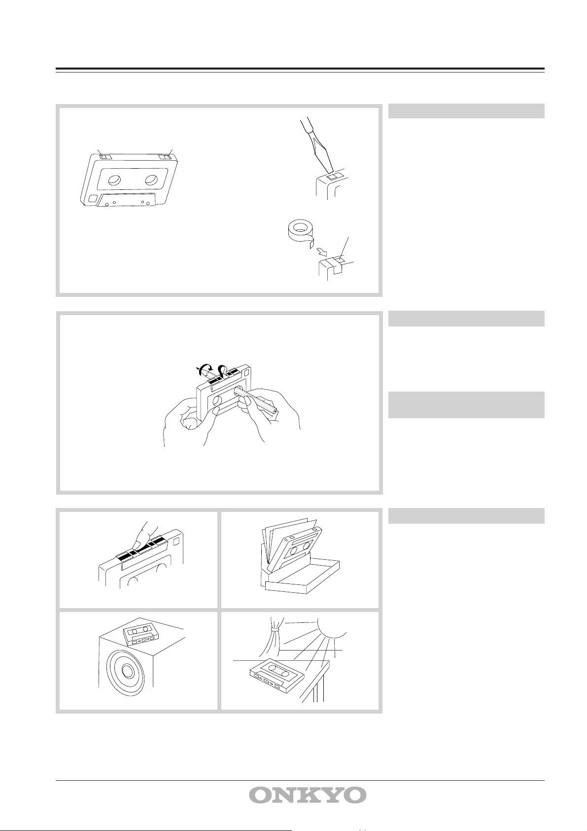
Examine cassette tapes carefully before using them with the TA-6711.
1
AB
A
2
A
High position
detection hole
Erasure Prevention
Cassette tapes are constructed with erasure
prevention niches on the back edge that are
initially covered by break-off tabs.
1. If you wish to protect a recording from
accidental erasure, break off the tab(s)
of the appropriate side(s). It will no
longer be possible to use the recording
button with such a cassette.
2. If at some later date you wish to re-
record the cassette, simply cover the
openings with small pieces of cellophane tape.
Tape Slack
Slack in the tape (tape not stretched tightly)
can cause tangling around the pinch roller
and capstan and jam the mechanism.
Remove any tape slack with a pencil or
similar device as shown in the diagram.
A
A
No! No!
Tapes which are Not
Recommended
1. C120 tapes
C120 tape is thin and therefore easily
broken. There is a possibility that tape
could get caught up by the pinch roller
or capstan.
2. Endless tapes
Do not use endless tapes.
Tape Storage
• Do not touch the tape surface.
• Do not put thick paper or cardboard
labels in the cassette holder.
• Do not put tapes near magnetic sources
(speakers, amplifiers, TVs, etc.). Your
important recording might be erased or
damaged.
• Do not expose cassettes to direct
sunlight.
14
No! No!
Page 15

Troubleshooting Guide
The following guide lists problems which do not require professional servicing. If, however, the problem cannot be remedied using this
guide, contact an Onkyo authorized service center for assistance.
• No power.
Cause: Power cord plug is loose
Remedy: Insert plug properly into outlet.
• Playback but no sound.
Cause: Hookup incorrect.
Remedy: Check and hook up correctly according to
page
5.
Cause: Stereo amplifier input selector switch is set to
wrong
position.
Remedy: Change switch position.
• Tape does not move.
Cause: Slack tape wound around pinch roller.
Remedy: Take up slack with a pencil (see page 14).
• REC button does not engage.
Cause: No tape in cassette holder.
Remedy: Load cassette tape.
Cause: Erasure prevention tab(s) removed.
Remedy: Change cassette or cover tab hole with
cello-
phane tape.
• Hoarse sound, balance unstable.
Cause: Playback head dirty.
Remedy: Clean head (see page 16).
Cause: Tape is stretched.
Remedy: Replace cassette.
Cause: Connecting cables not inserted firmly.
Remedy: Insert plugs firmly.
Cause: External flux leakage from nearby amplifier or
TV set.
Remedy: Move deck away from hum source.
• High frequencies too strong.
Cause: Dolby NR encoded tape played back with NR
off.
Remedy: Select the appropriate NR mode using the
DOLBY NR button. (Dolby B or C) for the
tape being played back.
Cause: Incorrect equalization.
Remedy: Confirm that cassette has tape type
detection
holes.
• No high frequency sounds.
Cause: Tape not encoded with Dolby NR played back
with Dolby B or C NR on.
Remedy: Select the appropriate NR mode using the
DOLBY NR button (OFF).
Cause: Heads have become dirty.
Remedy: Clean (see page 16).
• The skip function does not operate properly.
Cause: The silent sections between selections are too
short or noisy.
Remedy: Use a cassette with sufficiently silent
sections
of sufficient length between selections.
• Excessive noise and tape hiss.
Cause: Head has become magnetized.
Remedy: Demagnetize (see page 16).
Cause: Tape with high noise level.
Remedy: Replace cassette.
• Distorted sound.
Cause: Distortion in tape.
Remedy: Tape is probably bad but confirm by
listening
to another.
• Recordings are distorted.
Cause: Recording was done at too high a level.
Remedy: Readjust REC LEVEL knob according to
the
directions on page 11.
• Tape squeal and skipping.
Cause: Dirty heads, pinch rollers or capstan shafts.
Remedy: Clean (see page 16).
Cause: Cassette shell is binding tape or tape is
stretched.
Remedy: Change cassette or try correcting with fast
forward and rewind.
• Excessive hum during playback.
• Deck does not operate properly.
Cause: Tape transport control microcomputer has been
exposed to interference from power supply or static
electricity.
Remedy: Switch power off for about ten seconds.
15
Page 16

Cassette Deck
Specifications
Maintenance
This deck requires no lubrication.
Head, Pinch Roller and Capstan Cleaning
Playback sound quality can be greatly diminished if magnetic
particles are allowed to accumulate on the recording or playback
heads. Be sure to clean the heads periodically, normally 2 or 3
times a month, to maintain your deck's original performance.
Dirty heads will cause:
• Poor sound quality (loss of high frequency response)
• Decreased volume
• Skipping
• Incomplete erasure of previous recordings
If the pinch rollers and capstan are dirty, the tape may become
tangled and damaged by wrapping around the pinch roller and
capstan.
To prevent these problems, clean the heads, pinch rollers and
capstans with a cotton swab dipped in cleaning fluid.
Demagnetizing
Residual magnetism builds up in the heads after the cassette deck
has been used for an extended period of time. This buildup
introduces noise and static into tapes and impairs high frequency
response. To prevent this, demagnetize the heads and the other
metal parts in the area (like the capstan shafts) once every 50
hours of use. Keep the deck power off while using the demagnetizer. Also place tapes far away from the work area.
Recording and
Erase head
Capstan
playback head
Capstan
Pinch roller
Track Format: 4-tracks, 2-channels
Erasing System: AC erase
Tape Speed: 4.8 cm/sec. (1-7/8 i.p.s.)
Wow and Flutter: 0.045% (WRMS)
0.09% (DIN)
Frequency Response: 20—18,000Hz (normal)
(30—17,000Hz ±3dB)
20—19,000Hz (high)
(30—18,000Hz ±3dB)
20—20,000Hz (metal)
(30—19,000Hz ±3dB)
S/N Ratio: 60dB (metal tape, Dolby NR off)
A noise reduction of 10dB above
5kHz and 5dB at 1kHz is possible
with Dolby B NR. A noise reduction
of 20dB at 5kHz is possible with
Dolby C NR.
Input Jacks: LINE IN: 2
Input sensitivity: 80 mV
Input impedance: 40 kohms
MIC IN: 2
Input sensitivity: 5 mV
Input impedance: 50 kohms
Output Jacks: LINE OUT: 2
Standard output level: 500 mV
(0dB)
Optimum load impedance: over
50 kohms
Motors: DC servo motor: 1
DC motor: 2
Heads: REC/PB: Special Hard Permalloy x 1
Erase head: Sendust x 1
Power Supply Rating: U.S.A and Canadian models:
AC 120 V 60 Hz
European models:
AC 230 V, 50Hz
Worldwide models:
AC 120 and 220-230 V,
Switchable 50/60 Hz
Power Consumption: 16 watts
Dimensions: 435(W) x 131(H) x 370(D)mm
17-1/18" x 5-3/16" x 14-9/16"
Weight: 7.2 kg. (15.9 lbs.)
SN29342245
2
Specifications and external appearance are subject to change
without notice because of product improvements.
Sales & Product Planning Div. : 2-1, Nisshin-cho, Neyagawa-shi, OSAKA 572, JAPAN
Tel: 0720-31-8111 Fax: 0720-33-5222
ONKYO U.S.A. CORPORATION
200 Williams Drive, Ramsey, N.J. 07446, U.S.A.
Tel: 201-825-7950 Fax: 201-825-8150
ONKYO EUROPE ELECTRONICS GmbH
Industriestrasse 18-20, 82110 Germering, GERMANY
Tel: 089 84 93 20 Fax: 089 84 93 226
ONKYO FRANCE
Immeuble Le Diamant, Domaine Technologique de Saclay, 4 Rue René Razel,
91892 SACLAY, FRANCE Tel: (1) 69 33 14 00 Fax: (1) 69 41 35 84
Printed in Japan
E
 Loading...