

Page 1

AM/FM Tuner
Contents
Introduction.................................... 2
T-4555
(European model)
DAB/AM/FM Tuner
T-4555
(U.K. model)
Instruction Manual
Thank you for purchasing an Onkyo Tuner. Please
read this manual thoroughly before making connections and plugging in the unit.
Following the instructions in this manual will enable
you to obtain optimum performance and listening
enjoyment from your new Tuner.
Please retain this manual for future reference.
Connections ................................. 10
Enjoying Audio Sources.............. 15
Troubleshooting ........................... 26
Specifications .............................. 27
E
n
Page 2
WARNING:
TO REDUCE THE RISK OF FIRE OR ELECTRIC
SHOCK, DO NOT EXPOSE THIS APPARATUS
TO RAIN OR MOISTURE.
CAUTION:
TO REDUCE THE RISK OF ELECTRIC SHOCK,
DO NOT REMOVE COVER (OR BACK). NO
USER-SERVICEABLE PARTS INSIDE. REFER
SERVICING TO QUALIFIED SERVICE
PERSONNEL.
Important Safety Instructions
1. Read these instructions.
2. Keep these instructions.
3. Heed all warnings.
4. Follow all instructions.
5. Do not use this apparatus near water.
6. Clean only with dry cloth.
7. Do not block any ventilation openings. Install in
accordance with the manufacturer’s instructions.
8. Do not install near any heat sources such as radiators, heat registers, stoves, or other apparatus
(including amplifiers) that produce heat.
9. Do not defeat the safety purpose of the polarized or
grounding-type plug. A polarized plug has two
blades with one wider than the other. A grounding
type plug has two blades and a third grounding
prong. The wide blade or the third prong are provided for your safety. If the provided plug does not
fit into your outlet, consult an electrician for
replacement of the obsolete outlet.
10. Protect the power cord from being walked on or
pinched particularly at plugs, convenience receptacles, and the point where they exit from the apparatus.
11. Only use attachments/accessories specified by the
manufacturer.
12.
Use only with the cart, stand,
tripod, bracket, or table specified by the manufacturer, or
sold with the apparatus.
When a cart is used, use caution when moving the cart/
apparatus combination to
avoid injury from tip-over.
13. Unplug this apparatus during lightning storms or
when unused for long periods of time.
14. Refer all servicing to qualified service personnel.
Servicing is required when the apparatus has been
damaged in any way, such as power-supply cord or
plug is damaged, liquid has been spilled or objects
have fallen into the apparatus, the apparatus has
been exposed to rain or moisture, does not operate
normally, or has been dropped.
PORTABLE CART WARNING
S3125A
WARNING
RISK OF ELECTRIC SHOCK
DO NOT OPEN
The lightning flash with arrowhead symbol, within an
equilateral triangle, is intended to alert the user to the
presence of uninsulated “dangerous voltage” within
the product’s enclosure that may be of sufficient
magnitude to constitute a risk of electric shock to
persons.
The exclamation point within an equilateral triangle is
intended to alert the user to the presence of important
operating and maintenance (servicing) instructions in
the literature accompanying the appliance.
AVIS
RISQUE DE CHOC ELECTRIQUE
NE PAS
OUVRIR
15. Damage Requiring Service
Unplug the apparatus from the wall outlet and refer
servicing to qualified service personnel under the
following conditions:
A. When the power-supply cord or plug is damaged,
B. If liquid has been spilled, or objects have fallen
into the apparatus,
C. If the apparatus has been exposed to rain or
water,
D. If the apparatus does not operate normally by
following the operating instructions. Adjust only
those controls that are covered by the operating
instructions as an improper adjustment of other
controls may result in damage and will often
require extensive work by a qualified technician
to restore the apparatus to its normal operation,
E. If the apparatus has been dropped or damaged in
any way, and
F. When the apparatus exhibits a distinct change in
performance this indicates a need for service.
16. Object and Liquid Entry
Never push objects of any kind into the apparatus
through openings as they may touch dangerous voltage points or short-out parts that could result in a
fire or electric shock.
The apparatus shall not be exposed to dripping or
splashing and no objects filled with liquids, such as
vases shall be placed on the apparatus.
Don’t put candles or other burning objects on top of
this unit.
17. Batteries
Always consider the environmental issues and follow local regulations when disposing of batteries.
18. If you install the apparatus in a built-in installation,
such as a bookcase or rack, ensure that there is adequate ventilation.
Leave 20 cm (8") of free space at the top and sides
and 10 cm (4") at the rear. The rear edge of the shelf
or board above the apparatus shall be set 10 cm (4")
away from the rear panel or wall, creating a flue-like
gap for warm air to escape.
2
Page 3
Precautions
1. Recording Copyright —Unless it’s for personal use
only, recording copyrighted material is illegal without the permission of the copyright holder.
2. AC Fuse —The AC fuse inside the unit is not user-
serviceable. If you cannot turn on the unit, contact
your Onkyo dealer.
3. Care —Occasionally you should dust the unit all
over with a soft cloth. For stubborn stains, use a soft
cloth dampened with a weak solution of mild detergent and water. Dry the unit immediately afterwards
with a clean cloth. Don’t use abrasive cloths, thinners, alcohol, or other chemical solvents, because
they may damage the finish or remove the panel lettering.
4. Power
WARNING
BEFORE PLUGGING IN THE UNIT FOR THE
FIRST TIME, READ THE FOLLOWING SECTION CAREFULLY.
AC outlet voltages vary from country to country.
Make sure that the voltage in your area meets the
voltage requirements printed on the unit’s rear panel
(e.g., AC 230 V, 50 Hz or AC 120 V, 60 Hz).
The power cord plug is used to disconnect this unit
from the AC power source. Make sure that the plug
is readily operable (easily accessible) at all times.
For American Models
Pressing the [STANDBY/ON] button to select
Standby mode does not fully shutdown the unit. If
you do not intend to use the unit for an extended
period, remove the power cord from the AC outlet.
5. Never Touch this Unit with Wet Hands
handle this unit or its power cord while your hands
are wet or damp. If water or any other liquid gets
inside this unit, have it checked by your Onkyo
dealer.
6. Handling Notes
• If you need to transport this unit, use the original
packaging to pack it how it was when you originally bought it.
• Do not leave rubber or plastic items on this unit
for a long time, because they may leave marks on
the case.
• This unit’s top and rear panels may get warm
after prolonged use. This is normal.
• If you do not use this unit for a long time, it may
not work properly the next time you turn it on, so
be sure to use it occasionally.
—Never
For British models
Replacement and mounting of an AC plug on the power
supply cord of this unit should be performed only by
qualified service personnel.
IMPORTANT
The wires in the mains lead are coloured in accordance
with the following code:
Blue: Neutral
Brown: Live
As the colours of the wires in the mains lead of this
apparatus may not correspond with the coloured markings identifying the terminals in your plug, proceed as
follows:
The wire which is coloured blue must be connected to
the terminal which is marked with the letter N or
coloured black.
The wire which is coloured brown must be connected to
the terminal which is marked with the letter L or
coloured red.
IMPORTANT
The plug is fitted with an appropriate fuse. If the fuse
needs to be replaced, the replacement fuse must
approved by ASTA or BSI to BS1362 and have the same
ampere rating as that indicated on the plug. Check for
the ASTA mark or the BSI mark on the body of the fuse.
If the power cord’s plug is not suitable for your socket
outlets, cut it off and fit a suitable plug. Fit a suitable
fuse in the plug.
For European Models
Declaration of Conformity
We,
ONKYO EUROPE
ELECTRONICS GmbH
LIEGNITZERSTRASSE 6,
82194 GROEBENZELL,
GERMANY
declare in own responsibility, that the ONKYO product
described in this instruction manual is in compliance with the
corresponding technical standards such as EN60065,
EN55013, EN55020 and EN61000-3-2, -3-3.
GROEBENZELL, GERMANY
K. MIYAGI
ONKYO EUROPE ELECTRONICS GmbH
Memory backup
The T-4555 uses a battery-less memory backup system
in order to retain radio presets and other settings when
it’s unplugged or in the case of a power failure.
Although no batteries are required, the T-4555 must be
plugged into an AC outlet in order to charge the backup
system.
Once it has been charged, the T-4555 will retain the settings for several weeks, although this depends on the
environment and will be shorter in humid climates.
3
Page 4
❑
❑
❑
❑
❑
❑
❑
❑
❑
❑
❑
❑
❑
❑
❑
❑
❑
❑
❑
Features
Tuner board upgrade capability
12V trigger IN/OUT
RS232 port
IR IN/OUT
Hi-rigidity, anti-resonant chassis
Aluminium front panel
RI (Remote Interactive) capable
European Model
Automatic AM/FM tuning
40 AM/FM presets
RDS (Radio Data System)
Preset auto scan
Direct tuning
U.K. Model
Automatic AM/FM/DAB tuning
40 AM/FM/DAB presets
RDS (Radio Data System)
DAB auto scanning (Band III/L-Band)
Preset auto scan
Direct tuning
Ground isolation circuit for digital/analog
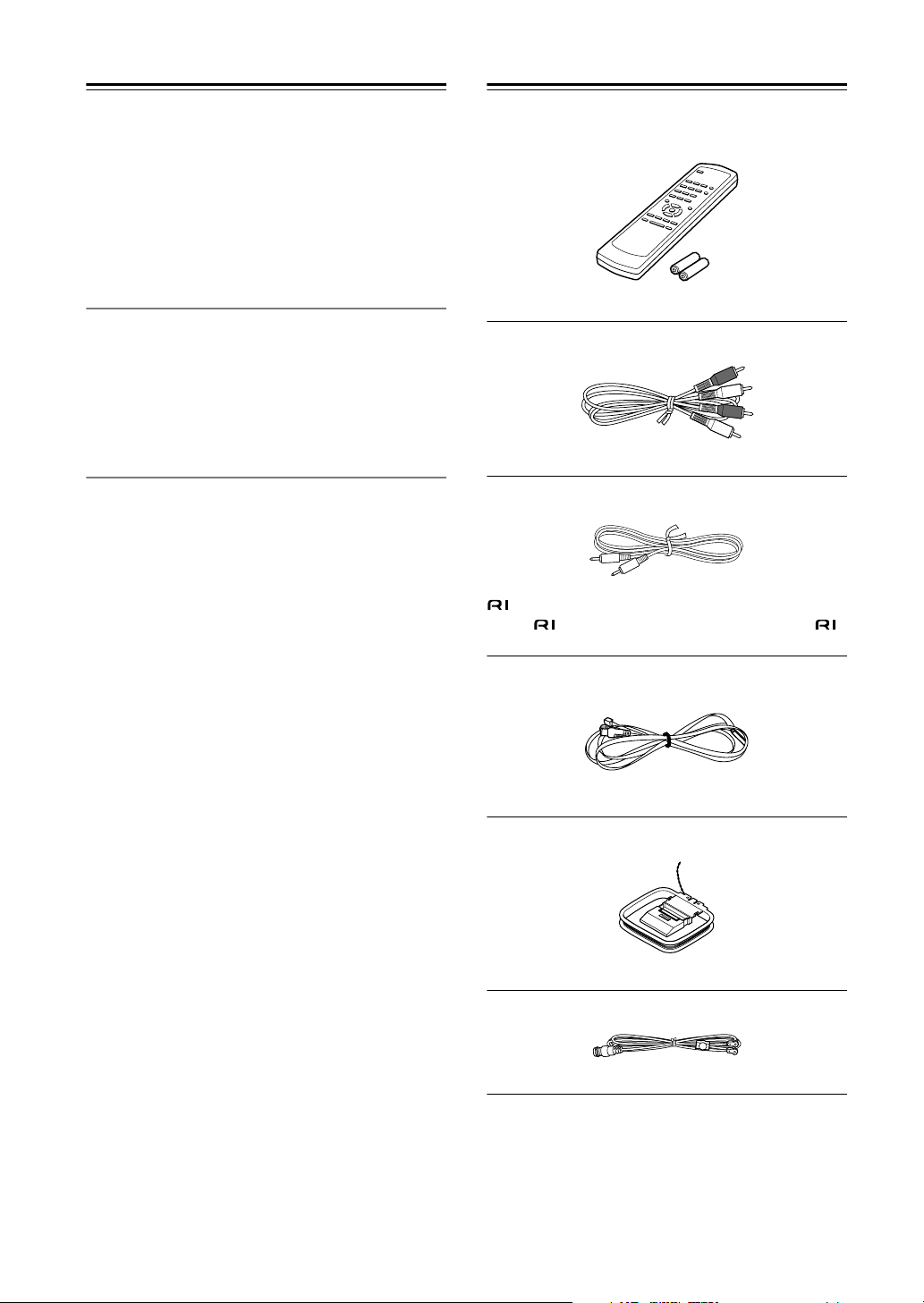
Supplied Accessories
Make sure you have the following accessories:
Remote controller and two batteries (AA/R6)
Audio cable (60 cm)
cable (60 cm)
To use , the T-4555 must be connected with an
cable and an audio cable.
Indoor FM antenna
AM loop antenna
DAB antenna (with U.K. model)
* In catalogs and on packaging, the letter added to the end of
the product name indicates the color of the T-4555. Specifications and operation are the same regardless of color.
4
Page 5

Contents
Introduction
Important Safety Instructions.....................................................................................2
Precautions..................................................................................................................3
Features .......................................................................................................................4
Supplied Accessories .................................................................................................4
Getting to Know the T-4555........................................................................................6
Front Panel ............................................................................................................6
Display...................................................................................................................6
Rear Panel.............................................................................................................7
Remote Controller .......................................................................................................8
Remote Controller .................................................................................................8
Before Using the T-4555 .............................................................................................9
Installing the Batteries ...........................................................................................9
Aiming the Remote Controller ...............................................................................9
Connections
Connecting Antennas ...............................................................................................10
Connecting the Indoor FM Antenna.....................................................................10
Connecting the AM Loop Antenna.......................................................................10
Connecting the T-4555..............................................................................................12
Connecting to an Amplifier ..................................................................................12
About the System Functions................................................................................12
Connecting the 12V Trigger Jacks ......................................................................13
Controlling Components That Are Out of Range.................................................14
Enjoying Audio Sources
Turning On and Listening to AM and FM Radio .....................................................15
Turning On the T-4555 ........................................................................................15
Setting the Display Brightness.............................................................................15
Listening to AM and FM Radio ............................................................................15
Tuning into Stations by Frequency ......................................................................16
Using RDS...........................................................................................................17
Listening to DAB Digital Radio ................................................................................19
DAB Setup...........................................................................................................20
Using Presets ............................................................................................................22
Presetting Your Favorite Stations........................................................................22
Selecting Presets.................................................................................................22
Deleting Presets ..................................................................................................22
Changing the Remote ID...........................................................................................23
Optional Tuner Boards..............................................................................................24
AM Frequency Step Setup ..................................................................................24
Installing a Board.................................................................................................25
Others
Troubleshooting ........................................................................................................26
If you can’t resolve an issue, try resetting the AV receiver by holding down the [MEMORY] button and pressing the [STANDBY/ON] button.
Specifications ............................................................................................................27
5
Page 6
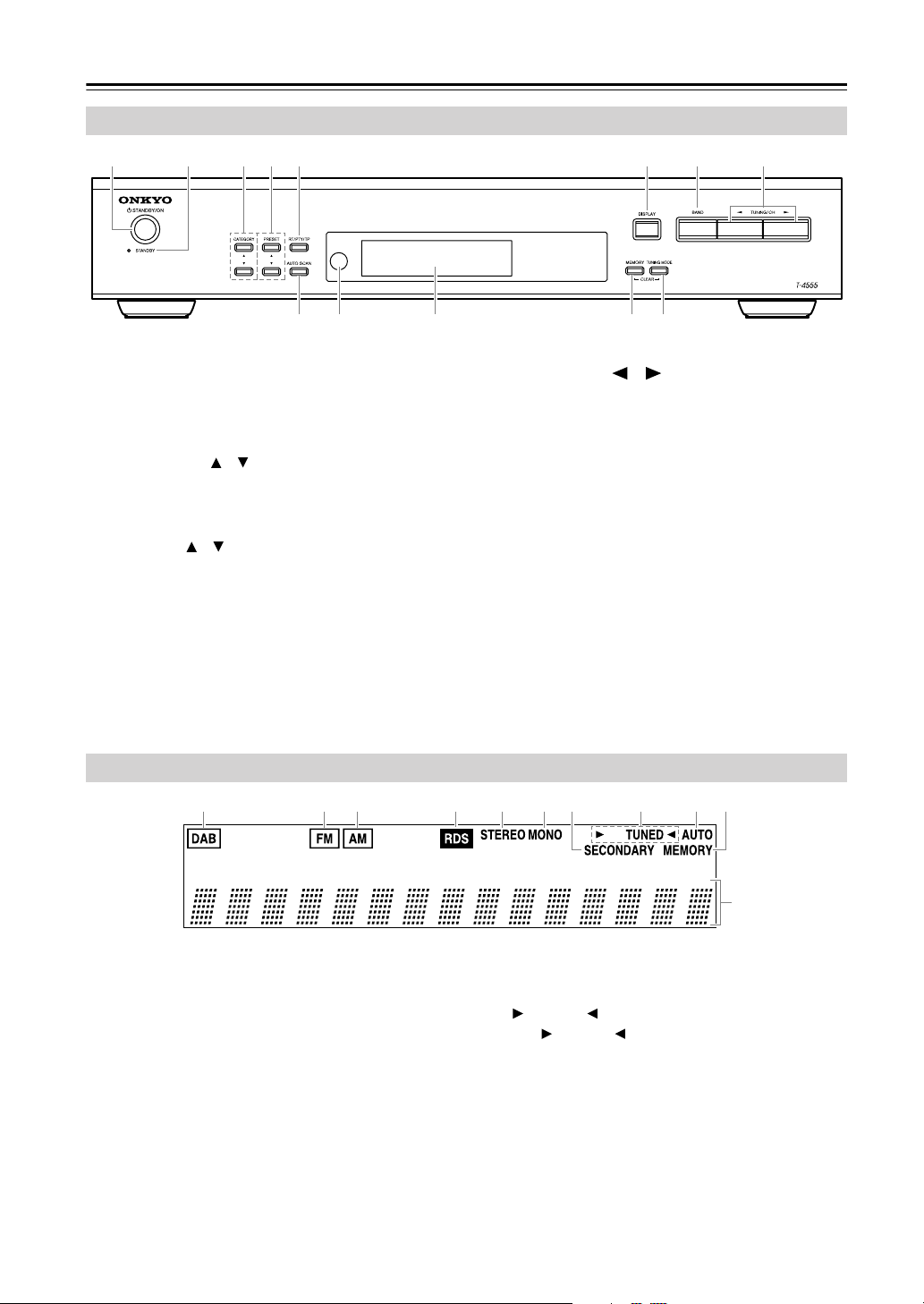
Getting to Know the T-4555
Front Panel
FM
AM
A
BC45 67 8
9KJLM
For detailed information, refer to the pages in parentheses.
STANDBY/ON button (15)
A
Sets the T-4555 to On or Standby.
STANDBY indicator (15)
B
Lights up when the T-4555 is on Standby.
C
CATEGORY [ ]/[ ] buttons
Selects categories for satellite radio.
As of August 2006, these buttons are not used on the
European or U.K. T-4555.
PRESET [ ]/[ ] buttons (18, 22)
D
Used to select radio presets.
E
RT/PTY/TP button (18)
Used with RDS (Radio Data System).
F
DISPLAY button (20)
Used to view various information on the display.
BAND button (15, 18, 19)
G
Selects AM, FM, or DAB*.
*DAB requires C-DAB tuner board.
H
TUNING/CH [ ]/[ ] buttons (15, 19)
With AM and FM, these buttons are used for tuning.
With DAB, they’re used to select stations.
I
AUTO SCAN button (18, 19, 22)
Selects and outputs each radio preset in turn for 5
seconds. When tuned to an RDS FM station, it
searches for stations by PTY (Program Type) or TP
(Traffic Program). Also used to scan for available
DAB stations.
Remote control sensor (9)
J
Receives control signals from the remote controller.
Display
K
See below.
L
MEMORY button (22)
Used to store and delete radio presets.
M
TUNING MODE button (15, 22)
Selects the Auto or Manual tuning mode for AM
and FM radio.
6
Display
123456879J
DAB (requires C-DAB tuner board)
A
Lights up if the installed tuner board supports DAB.
When DAB is selected, a box appears around it.
B
Lights up if the installed tuner board supports FM.
When FM is selected, a box appears around it.
C
Lights up if the installed tuner board supports AM.
When AM is selected, a box appears around it.
D RDS
Lights up when the tuner is tuned to an FM radio
station that supports RDS (Radio Data System).
E STEREO
Lights up when radio reception is in stereo.
F MONO
Lights up when radio reception is in mono.
K
G SECONDARY
Lights up when tuned to an DAB station that’s
transmitting secondary multicast channels.
H TUNED
The TUNED indicator lights up when properly
tuned to a radio station. During Auto Tuning, the
Tuning Arrows flash.
I AUTO
Lights up when Auto Tuning mode is selected.
J MEMORY
Lights up when presetting radio stations.
K Message area
Various information is displayed here, including
radio preset numbers, tuning frequency, and so on.
Page 7
Getting to Know the T-4555—Continued
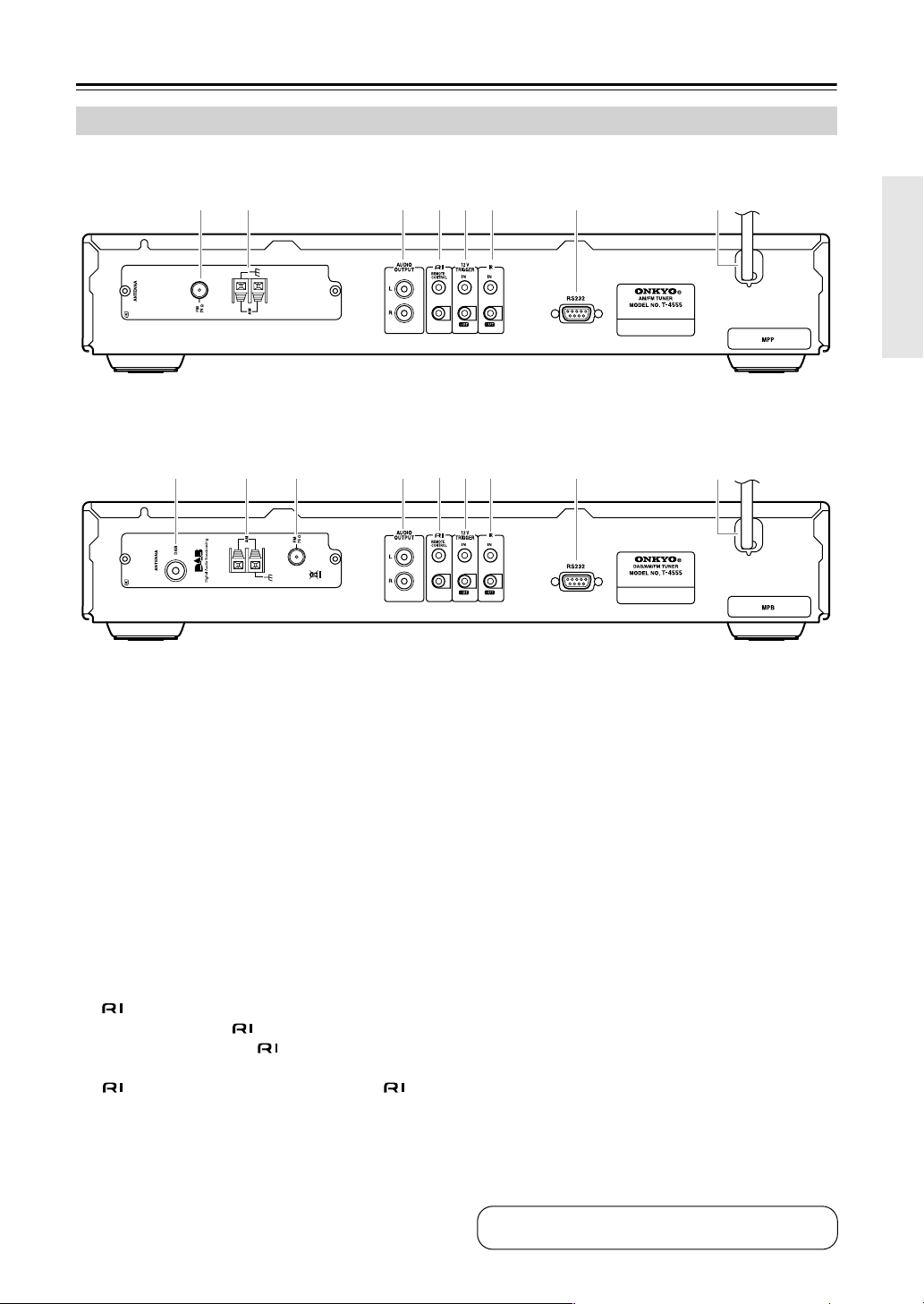
Rear Panel
■ European Model
Comes with C-AMFM tuner board installed.
32 4567 8 9
■ U.K. Model
Comes with C-DAB tuner board installed.
1234
For detailed information, refer to the pages in parentheses.
5
A DAB ANTENNA (C-DAB tuner board only)
(11)
This jack is for connecting the supplied DAB
antenna.
B AM ANTENNA (10)
These push terminals are for connecting the supplied AM loop antenna or an outdoor AM antenna.
C FM 75Ω ANTENNA (10)
This jack is for connecting the supplied indoor FM
antenna or an outdoor FM antenna.
D AUDIO OUTPUT (12)
Using the supplied audio cable, connect these output jacks to an analog audio input on your amp.
E REMOTE CONTROL (13)
These two identical (Remote Interactive) jacks
can be connected to the jacks on your other
Onkyo components for interactive control. To use
, the T-4555 must be connected with an
cable and an audio cable.
F 12V TRIGGER IN/OUT (13)
The 12V TRIGGER IN jack can be connected to the
12-volt trigger output on another component, so that
when the other component is turned on, the T-4555
turns on as well.
67 8
The 12V TRIGGER OUT jack can be connected to
the 12-volt trigger input on another component, so
that when the T-4555 is turned on, the other component turns on as well.
9
G IR IN/OUT (14)
A commercially available IR receiver can be connected to the IR IN jack, allowing you to control the
T-4555 while you’re in another room, or control it
when it’s out of sight, for example, installed in a
cabinet.
A commercially available IR emitter can be connected to the IR OUT jack to pass IR (infrared)
remote control signals through to other components.
H RS232
This port is for connecting the T-4555 to home
automation equipment and external controllers.
I Power cord (15)
The power cord should be connected to a suitable
wall outlet.
See pages 10–14 for connection information.
7
Page 8
Remote Controller
Remote Controller
1
2
3
4
5
6
7
8
9
J
K
L
M
N
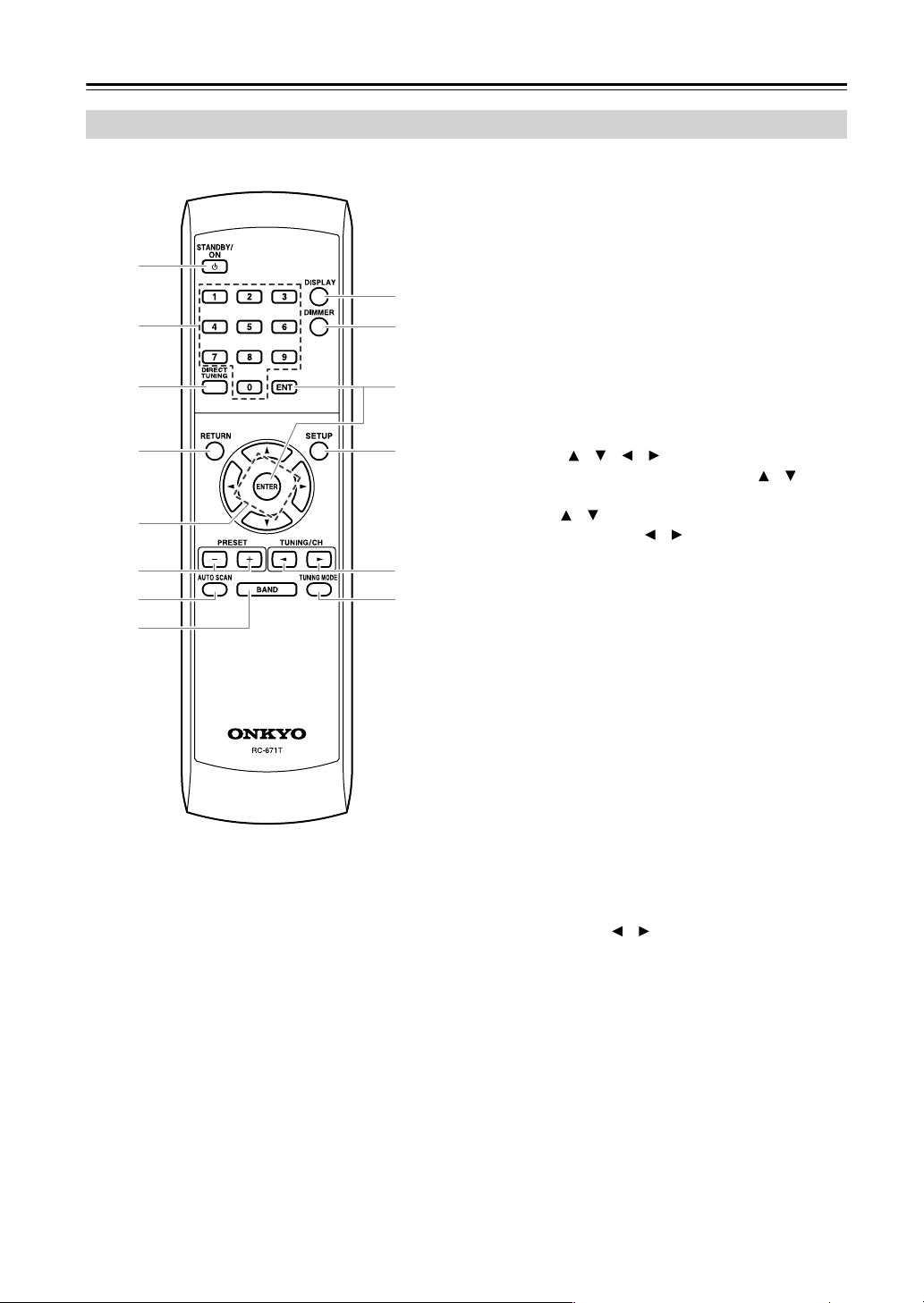
A STANDBY/ON button (15)
Sets the T-4555 to On or Standby.
B Number buttons (16, 23)
Used to select radio presets by number, and to enter
AM/FM station frequencies and DAB channel numbers in Direct Tuning mode.
C DIRECT TUNING button (16)
Selects the Direct Tuning mode. With AM and FM,
you can select a station directly by entering its frequency. Direct Tuning mode does not work with
DAB.
D RETURN button (23)
Returns to the previous display.
E Arrow [ ]/[ ]/[ ]/[ ] buttons (20, 21, 23, 24)
With AM and FM, the Up and Down [ ]/[ ] buttons are used for tuning. With DAB, the Up and
Down [ ]/[ ] buttons are used to select stations.
The Left and Right [ ]/[ ] buttons are not used by
the C-AMFM and C-DAB tuner boards.
F PRESET [+]/[–] buttons (22)
Used to select radio presets.
G AUTO SCAN button (19, 22)
Scans for DAB stations or FM stations that support
RDS.
H BAND button (15, 19)
Selects AM, FM, or DAB*.
I DISPLAY button (20)
Used to change the information shown on the display.
J DIMMER button (15)
Adjusts the display brightness.
K ENT and ENTER buttons (20, 21, 23, 24)
Used to confirm various functions and settings.
L SETUP button (20, 23, 24)
Selects Setup mode.
M TUNING/CH [ ]/[ ] buttons (15, 19)
With AM and FM, these buttons are used for tuning.
With DAB, they’re used to select stations.
N TUNING MODE button (15)
Selects the Auto or Manual Tuning mode for AM
and FM radio.
*DAB requires C-DAB tuner board.
8
Page 9
Before Using the T-4555
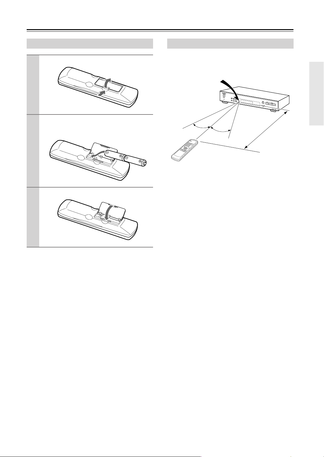
Installing the Batteries
Open the battery compartment, as shown.
1
Insert the two supplied batteries (AA) in
2
accordance with the polarity diagram
inside the battery compartment.
Close the battery compartment.
3
Notes:
• If the remote controller doesn’t work reliably, try
replacing the batteries.
• Don’t mix new and old batteries or different types of
batteries.
• If you intend not to use the remote controller for a
long time, remove the batteries to prevent damage
from leakage and corrosion.
• Flat batteries should be removed as soon as possible
to prevent damage from leakage and corrosion.
Aiming the Remote Controller
When using the remote controller, point it toward the
T-4555’s remote control sensor, as shown below.
Remote control sensor
T-4555
30˚
Notes:
• The remote controller may not work reliably if the
T-4555 is subjected to bright light, such as direct sunlight or inverter-type fluorescent lights. Keep this in
mind when installing.
• If another remote controller of the same type is used
in the same room, or the T-4555 is installed close to
equipment that uses infrared rays, the remote controller may not work reliably.
• Don’t put anything, such as a book, on the remote
controller because the buttons may be pressed inadvertently, thereby draining the batteries.
• The remote controller may not work reliably if the
T-4555 is installed in a rack behind colored glass
doors. Keep this in mind when installing.
• The remote controller will not work if there’s an
obstacle between it and the T-4555’s remote control
sensor.
30˚
5 m
Approx.
9
Page 10

Connecting Antennas
This section explains how to connect the supplied
indoor FM antenna, AM loop antenna, and DAB
antenna, and how to connect commercially available
outdoor FM and AM antennas.
■ European model
FM antenna jack
AM antenna push terminals
■ U.K. model
AM antenna push terminals
FM antenna jack
Connecting the Indoor FM Antenna
The supplied indoor FM antenna is for indoor use only.
Attach the FM antenna, as shown.
1
Connecting the AM Loop Antenna
The supplied indoor AM loop antenna is for indoor use
only.
Assemble the AM loop antenna, inserting
1
the tabs into the base, as shown.
Connect both wires of the AM loop
2
antenna to the AM push terminals, as
shown.
(The antenna’s wires are not polarity sensitive, so
they can be connected either way around).
Make sure that the wires are attached securely and
that the push terminals are gripping the bare
wires, not the insulation.
Push Insert wire Release
Insert the plug fully
into the jack.
Once the T-4555 is ready for use, you’ll need to
tune into an FM radio station and adjust the position of the FM antenna to achieve the best possible reception.
Use thumbtacks or something similar to
2
fix the FM antenna into position.
Thumbtacks, etc.
Caution: Be careful that you don’t injure yourself when using thumbtacks.
If you cannot achieve good reception with the supplied
indoor FM antenna, try using a commercially available
outdoor FM antenna instead.
10
Once the T-4555 is ready for use, you’ll need to
tune into an AM radio station and adjust the position of the AM antenna to achieve the best possible reception.
Keep the antenna as far away as possible from the
T-4555, TV, speaker cables, and power cords.
If you cannot achieve good reception with the supplied
indoor AM loop antenna, try using it with a commercially available outdoor AM antenna.
Page 11

Connecting Antennas—Continued
Connecting the DAB Antenna
(C-DAB Tuner Board Only)
Screw the supplied DAB antenna’s plug
1
onto the DAB ANTENNA jack.
Once the T-4555 is ready for use, you’ll need to
select a DAB station and adjust the position of
the DAB antenna to achieve the best possible
reception.
Use thumbtacks or something similar to
2
fix the DAB antenna into position.
•For safety reasons, outdoor antenna should be situated well away from power lines and other high-voltage equipment.
• Outdoor antenna must be grounded in accordance
with local regulations to prevent electrical shock hazards.
■ Using a TV/FM Antenna Splitter
It’s best not to use the same antenna for both FM and
TV reception, as this can cause interference problems. If
circumstances demand it, use a TV/FM antenna splitter,
as shown.
TV/FM antenna splitter
To T-4555 To TV (or VCR)
Connecting an Outdoor AM Antenna
If good reception cannot be achieved using the supplied
AM loop antenna, an outdoor AM antenna can be used
in addition to the loop antenna, as shown.
Outdoor antenna
Connecting an Outdoor FM Antenna
If you cannot achieve good reception with the supplied
indoor FM antenna, try a commercially available outdoor FM antenna instead.
Notes:
• Outdoor FM antennas work best outside, but usable
results can sometimes be obtained when installed in
an attic or loft.
•For best results, install the outdoor FM antenna well
away from tall buildings, preferably with a clear line
of sight to your local FM transmitter.
• Outdoor antenna should be located away from possible noise sources, such as neon signs, busy roads, etc.
AM loop antenna
Insulated antenna cable
Outdoor AM antennas work best when installed horizontally outside, but good results can sometimes be
obtained indoors by mounting horizontally above a window. Note that the AM loop antenna should be left connected.
Outdoor antenna must be grounded in accordance with
local regulations to prevent electrical shock hazards.
11
Page 12

Connecting the T-4555
Before Making Any Connections
• Refer to the instructions that came with the component you are connecting.
• Do not plug in the power cord until all other connections are complete.
• Do not bind audio cables with power cords and
speaker cables. Doing so may adversely affect the
sound quality.
•To prevent interference, keep power cords and
speaker cables as far away as possible from the
antennas.
Connecting to an Amplifier
Use the supplied audio cable to connect the T-4555’s
AUDIO OUTPUT L/R jacks to the TUNER IN jacks on
your amplifier, as shown.
To use the system functions, use the supplied
cable to make an connection (see the next column).
Supplied audio
cable
L
R
TUNER
T-4555
Supplied cable
Amplifier
RCA Audio Connection Color Coding
• Red plugs are used for the right channel, white
plugs are used for the left channel.
Left (white)
Right (red)
L
R
• Push each plug in all the way to make a good connection (loose connections can cause noise or malfunctions).
Right!
Wrong!
About the System Functions
If you connect the T-4555 to another Onkyo -capable component with the supplied cable and audio
cable, you can use the following system functions.
cables are special cables solely for use with Onkyo
products.
Auto Power On
When you turn on the T-4555, your Onkyo amplifier
will turn on automatically. (The amplifier’s POWER
switch must be set to ON for this to work.)
Direct Change
When you select a radio preset or change the band (AM,
FM, DAB), your Onkyo amplifier will automatically
select the T-4555 as the input source.
Remote Control Operation
You can control the T-4555 by using your Onkyo amplifier’s remote controller. See the amplifier’s instruction
manual for details.
Note:
• If the T-4555 is used with another Onkyo component,
such as the A-9555, refer to its instruction manual as
well.
12
Page 13

Connecting the T-4555—Continued
With (Remote Interactive), you can control your
-capable Onkyo CD player, T-4555, and so on with
your amp’s remote controller.
•To use , you must make an analog audio connection between your amplifier and each audio
component.
Onkyo amplifier
(A-9555), etc.
Onkyo CD player
(DX-7555), etc.
T-4555
jack
jack
Connecting the 12V Trigger Jacks
To have the T-4555 turn on automatically when another
component is turned on, connect the T-4555’s 12V
TRIGGER IN jack to a 12-volt trigger output on the
other component with a miniplug cable.
Likewise, to have another component turn on automatically when the T-4555 is turned on, connect the
T-4555’s 12V TRIGGER OUT jack to a 12-volt trigger
input on the other component with a miniplug cable.
Amplifier, AV receiver, etc.
MASTER VOLUME
12 V TRIGGER OUT
ZONE 2
12
V
TRIGGER
IN
STANDBY/ON
STANDBY
OFF
ZONE2
ZONE 2 LEVEL
PHONES
+
STEREO
TONE
DVD VIDEO 1 VIDEO 2
PURE AUDIO
MULTl CH
VCR 1 VCR 2
T-4555
CD player, etc.
LISTENING MODE
DISPLAY
DIGITAL INPUT
RT/PTY/TP
MEMORY
TUNING MODE
CLEAR
VIDEO 3 VIDEO 4 TAPE TUNER CD
TUNING / PRESET
ENTER
RETURN
SETUP
VIDEO 4 INPUT
LR
AUDIO
DIGITAL
SETUP MIC S VIDEO VIDEO
jack
Remote Interactive
Dock, etc.
cable
Notes:
• Push each plug in all the way to make a good connection.
• Use only dedicated cables for connections.
cables are supplied with Onkyo tuners and play-
ers (DVD, CD, etc.).
• Some components, including the T-4555, have two
jacks. They’re both the same, so use either one.
• jacks should be connected only to Onkyo components. Connecting them to another manufacturer’s
component may cause a malfunction.
• Some components may not support all functions.
See the manuals supplied with your other Onkyo
components for more information.
13
Page 14

Connecting the T-4555—Continued
Controlling Components That Are Out of Range
You can use the following multi-room kits to control the
T-4555 when it’s out of range of the remote controller:
• Multiroom AV distribution and control systems such
as those made by Niles
®
and Xantech®.
Controlling Other Out-of-range
Components
If another component is out of range of its remote controller, you can use a commercially available IR emitter
to retransmit the remote controller signals received at
the T-4555’s IR IN, as shown below.
Controlling the T-4555 When It’s Out of
Range
If the T-4555 is located in another room, installed in a
cabinet, or out of range of its remote controller, you can
use a commercially available IR receiver to pickup the
remote controller signals and feed them to the T-4555,
as shown below.
Connecting
block
IR IN
T-4555
Remote controller
IR Receiver
IR Receiver
Signal flow
IR IN
IR OUT
Connecting
block
T-4555
IR Emitter
Remote controller
Other component
Connect the IR emitter to the T-4555’s IR OUT, and
place the IR emitter in front of the other component’s
remote control sensor (usually located on its front
panel), as shown below. See the instructions supplied
with the IR emitter.
Other component
From the
connecting block
Miniplug cable
Remote
control
sensor
IR Emitter
Inside
cabinet
Connect the IR receiver to the T-4555 as shown below.
From the connecting block
Miniplug cable
T-4555
14
Miniplug
Signal flow
IR Emitter
T-4555
Signal flow
Only remote controller signals received by the T-4555’s
IR IN are fed through to the IR OUT. Signals picked up
by the T-4555’s remote control sensor are not output.
Page 15

Turning On and Listening to AM and FM Radio
STANDBY/ON
STANDBY indicator
STANDBY/ON
BAND
TUNING/CH
TUNING MODE
DIMMER
TUNING/CH
TUNING MODE
BAND
Listening to AM and FM Radio
1
Remote controller
2
Remote controller
/
Press the [BAND] button repeatedly to select AM or FM.
The or indicator lights up.
Press the [TUNING MODE] button repeatedly to select Auto or
Manual Tuning mode.
•Auto Tuning Mode
The AUTO indicator appears and
stereo radio reception is possible.
• Manual Tuning Mode
The MONO indicator appears and
radio reception will be in mono.
AUTO indicator
MONO indicator
Turning On the T-4555
1
2
Remote controller
Connect the power cord to a suitable wall outlet.
Press the [STANDBY/ON] button
on the T-4555 or remote controller.
The T-4555 turns on, and the
STANDBY indicator goes off.
To turn off the T-4555, press the
[STANDBY/ON] button. The T-4555
will enter Standby mode.
Note that the T-4555 is not completely
shutdown in Standby mode.
Setting the Display Brightness
With this function, you can adjust the brightness of the
display.
Remote controller
Press the remote controller’s
[DIMMER] button repeatedly to
select: dim, dimmer, or normal
brightness.
3
Remote controller
Tuning into weak stereo FM stations
If the signal from a stereo FM station is weak, it may be
impossible to get good reception. In this case, switch to
Manual Tuning mode and listen to the station in mono.
Use the TUNING/CH [ ]/[ ] buttons to tune into a station.
In Auto Tuning mode, once a station is
found, tuning stops automatically.
This model changes FM frequency in
0.05 MHz steps, 9 kHz steps for AM.
In Manual Tuning mode, the frequency
stops changing when you release the
buttons. Press the buttons repeatedly to
change the frequency one step at a
time.
When tuned into a station, the
TUNED indicator appears.
TUNED
15
Page 16

Turning On and Listening to AM and FM Radio—Continued
Number buttons
DIRECT TUNING
Tuning into Stations by Frequency
You can tune into AM and FM stations directly by
entering the appropriate frequency.
1
Remote controller
2
Remote controller
Press the [DIRECT TUNING] button.
(Actual display depends on country.)
Within 8 seconds, use the number buttons to enter the frequency of the radio station.
For example, to tune into an FM station at 87.5 MHz, press [8], [7], and
[5].
Adjusting the Antennas
Adjusting and installing the FM antenna
Choose a location for the FM antenna while
listening to an FM station.
1
2
Adjusting the AM antenna
Adjust the location and position of the
AM antenna while listening to an AM station to achieve the best possible reception.
Change the direction of the
antenna to achieve the best
possible reception.
16
Affix the antenna with a thumbtack. (Do not
push the thumbtack through the antenna.)
Caution: Be careful not to prick your finger!
Page 17

Turning On and Listening to AM and FM Radio—Continued
Using RDS
RDS only works with European and U.K. models and
only in areas where RDS broadcasts are available.
■ What is RDS?
RDS stands for Radio Data System and it’s a method of
transmitting data in FM radio signals. It was developed
by the European Broadcasting Union (EBU) and is
available in most European countries. Many FM stations use it these days. In addition to displaying text
information, RDS can also help you find radio stations
by type (e.g., news, sport, rock, etc.).
The T-4555 supports the following types of RDS data:
PS (Program Service)
When tuned to an RDS station that’s broadcasting PS
information, the station’s name will be displayed. Pressing the [DISPLAY] button will display the current frequency for 3 seconds.
RT (Radio Text)
When tuned to an RDS station that’s broadcasting RT
text information, the text will be shown on the display
(see page 18).
PTY (Program Type)
With PTY, you can search for radio stations by type (see
page 18).
TP (Traffic Program)
With TP, you can listen to traffic information (see
page 18).
Notes:
• In some cases, the text characters displayed on the AV
receiver may not be identical to those broadcast by
the radio station. Also, unexpected characters may be
displayed when unsupported characters are received.
This is not a malfunction.
• If the signal from an RDS station is weak, RDS data
may be displayed intermittently or not at all.
Program Types Used in Europe (PTY)
Type Display Description
None NONE No program type.
News
reports
Current
affairs
Information INFO General information such as
Sport SPORT Live sports action, sports
Education EDUCATE Formal educational programs.
Drama DRAMA Radio plays and serials.
Culture CULTURE Cultural programs (including
Science
and
technology
Var ied VARIED Speech-based programs not
Pop music POP M Popular commercial music,
Rock music ROCK M Popular music with an
Middle of
the road
music
Light
classics
Serious
classics
Other music OTHER M Music styles not covered by
Alarm ALARM When an RDS station is
NEWS Reports on current events and
happenings.
AFFAIRS Topical reporting of current
affairs, often with a wider
range of topics than news
reports.
weather forecasts, consumer
affairs, medical help, etc.
news, and interviews.
religious affairs).
SCIENCE Programs about the natural
sciences and technology.
covered by the above
categories (e.g., quizzes,
panel games, and comedy).
usually from past or present
sales charts (e.g., Top 40).
alternative appeal, often not
appearing on sales charts.
M.O.R.M Easy listening music (as
opposed to Pop, Rock, or
Classical).
LIGHT M Classical music for general
rather than specialist
appreciation.
CLASSICS Performances of major
orchestral works, symphonies,
chamber music, etc. (including
the Grand Opera).
the above categories (e.g.,
Jazz, Rhythm & Blues, Folk,
Country, and Reggae).
making an emergency
broadcast, ALARM will flash
on the display.
17
Page 18

Turning On and Listening to AM and FM Radio—Continued
BANDRT/PTY/TP
AUTO SCAN
PRESET
/
Displaying Radio Text (RT)
When tuned to an RDS station that’s broadcasting RT
text information, you can display information.
Press the [RT/PTY/TP] button
once.
The RT information scrolls across the
display.
Notes:
• While the T-4555 waits for RT information, “Waiting” appears on the display.
• If “No Text Data” appears on the display, no RT text
information is available.
Finding Stations by Type (PTY)
You can search for radio stations by type.
1
Use the [BAND] button to select
FM.
5
When the station you want to listen to is found, press [AUTO
SCAN].
If no stations are found, “Not Found”
appears on the display.
Listening to Traffic Information (TP)
You can listen to traffic information and search for TP
radio stations.
1
2
3
Use the [BAND] button to select
FM.
Press the [RT/PTY/TP] button
three times.
If the current radio station is broadcasting TP (Traffic Program), “[TP]” will
appear on the display and traffic information will be heard as and when it’s
broadcast. If “TP” without square
brackets appears, it means that the station is not broadcasting TP.
To locate a station that is broadcasting TP, press [AUTO SCAN].
The T-4555 searches until it finds a
station that’s broadcasting TP.
If no stations are found, “Not Found”
appears on the display.
18
2
3
4
Press the [RT/PTY/TP] button
twice.
The current program type appears on
the display.
Use the PRESET [ ]/[ ] buttons
to select the type of program you
want.
See the list of program types on
page 17.
To start the search, press [AUTO
SCAN].
The T-4555 searches until it finds a
station of the type you specified, at
which point it stops briefly before continuing with the search.
Page 19

Listening to DAB Digital Radio
Using the Auto Tuning Function Manually
TUNING/CH
AUTO SCAN BAND
If a new DAB station is introduced, or you move to a
new area, you can run the Auto Tuning function again.
Remote controller
To start the Auto Tuning function,
press the [AUTO SCAN] button.
The number of stations found and the
scanning progress are shown on the
display.
AUTO SCAN
Remote controller
TUNING/CH
BAND
/
Press the [BAND] button repeatedly to select DAB.
The indicator lights up.
When tuned into a DAB station, the
TUNED indicator appears.
Tuned indicatorDAB indicator
Station name
To cancel Auto Tuning, press the [AUTO SCAN] button
again.
Selecting DAB Stations
Use the TUNING/CH [ ]/[ ] buttons to select a DAB station.
If a secondary service is available, a
right angle bracket (>) is displayed.
Remote controller
Press the Right Arrow [ ] button to
listen to the secondary service.
“>”
While the secondary service is
selected, a left angle bracket (<) is displayed and SECONDARY indicator
lights up. Press the Left Arrow [ ]
button to return to the primary service.
“SECONDARY”
Selecting DAB for the Very First Time
The very first time you select DAB, the Auto Tuning
function automatically scans the DAB Band III and
L-Band for the multiplexes (i.e., stations) available in
your area.
Once the scanning process is complete, the first station
that was detected is selected.
“<”
When you select a station that you’ve
selected a lot in the past, the letter F
(short for Favorite) is displayed.
“F”
If you select a station that cannot be
received properly, a question mark (?)
is displayed.
“?”
19
Page 20

Listening to DAB Digital Radio—Continued
Displaying DAB Radio Information
Press the [DISPLAY] button repeatedly to display more
information about the current DAB station.
1. DLS (Dynamic Label Segment)
When tuned to a station that’s broadcasting DLS text
data, the text will scroll across the display.
(Scroll)
2. Program Type
Displays the type of program.
DAB Setup
You can configure DAB digital radio with these settings.
3. Bit Rate and Audio Mode
Displays the station’s bit rate and audio mode (stereo, mono, or joint stereo).
1
Remote controller
ENTER
///
Press the [SETUP] button.
SETUP
4. Signal Quality
Displays the signal quality.
0–59: Poor reception
60–79: Good reception
80–100: Excellent reception
5. Multiplex Name
Displays the name of the current multiplex.
6. Multiplex Number and Frequency
Displays the number and frequency of the current
multiplex.
2
Remote controller
Use the Up and Down Arrow
[ ]/[ ] buttons to select a setting.
Each item is explained below.
St. List (Station Listing)
With this setting, you can sort the available stations
alphabetically, by multiplex, favorites, or active stations.
Use the Left and Right Arrow [ ]/[ ] buttons to select
the following options, and then press [ENTER].
Alp Odr (Alphabetical Order): Sort stations alpha-
betically. This is the default setting.
Mlt Odr (Multiple Order): Sort stations by multi-
plex.
Fav Odr (Favorite Order): Sort stations by favorites.
The stations you select the most will appear at the
top of the list.
Act Odr (Active Station Order): Sort by active sta-
tions. Receivable stations appear at the top of the
list. stations that cannot be received properly
appear at the bottom of the list.
Trim (Trim Station): Removes stations that cannot
be received properly from the listing.
20
Page 21

Listening to DAB Digital Radio—Continued
Scan Mode
This setting determines which DAB bands are scanned
by the Auto Tuning function (see page 19).
Use the Left and Right Arrow [ ]/[ ] buttons to select
the following options, and then press [ENTER].
UK: Band III (11B–12D).
WorldW (Worldwide): Band III (5A–13F) and
L-Band (LA–LW). This is the default setting.
DRC Value
With the DRC (Dynamic Range Control) setting, you
can reduce the dynamic range of DAB digital radio so
that you can still hear quiet parts even when listening at
low volume levels—ideal for listening to the radio late at
night when you don’t want to disturb anyone.
Use the Left and Right Arrow [ ]/[ ] buttons to select
from the following options, and then press [ENTER].
1 (default): Large reduction in dynamic range.
1/2: Small reduction in dynamic range.
0: DRC off.
Band
With the Band setting, you can choose the DAB band
you want to use, and display the current reception quality and the reception quality necessary to decode the
current multiplex.
Use the Left and Right Arrow [ ]/[ ] buttons to select
from the following options, and then press [ENTER].
Band III: 5A–13F
L-Band: LA-LW
Display example:
Channel If reception is poor, “Bad” is
displayed. If reception is
good, “Good” is displayed.
You can adjust the position and direction of the DAB
antenna while monitoring the signal strength on the display.
To make “Good” appear, adjust the antenna to get the
best signal strength.
21
Page 22

Using Presets
AUTO SCAN
PRESET
PRESET –/+
AUTO SCAN
/
Presetting Your Favorite Stations
You can store any combination of up to 40 of your
favorite AM, FM, and DAB radio stations as presets.
■ Using the T-4555:
MEMORY
TUNING MODE
Selecting Presets
■ Using the PRESET buttons:
To select a preset, use the
T-4555’s PRESET [ ]/[ ] buttons,
or the remote controller’s PRESET [+]/[–] buttons.
Remote controller
■ Using the Auto Scan function:
Press the [AUTO SCAN] button.
The Auto Scan function automatically
selects and outputs each radio preset in
Remote controller
turn for 5 seconds.
When you hear the station that you
want to listen to, press the [AUTO
SCAN] button again to stop auto scanning.
1
2
3
4
Tune into the station that you
want to store as a preset.
Press the [MEMORY] button.
The MEMORY indicator appears and
the preset number flashes.
While the MEMORY indicator is
displayed (about 8 seconds), use
the PRESET [ ]/[ ] buttons to
select a preset from 1 through 40.
Press the [MEMORY] button
again to store the station or
channel.
The station or channel is stored and the
preset number stops flashing.
Repeat this procedure for all of your
favorite radio stations.
Deleting Presets
■ Using the T-4555:
1
2
Select the preset that you want to
delete.
See the previous section.
While holding down the [MEMORY] button, press the [TUNING
MODE] button.
The preset is deleted and its number
disappears from the display.
22
Page 23

Changing the Remote ID
If the T-4555’s remote controller interferes with other
Onkyo components located in the same room, you can
change the remote control ID. You can select remote
control ID #1, #2, or #3. By default, the remote control
ID is set to #1. If you change the ID, you must also
change the ID on the remote controller to match, as
explained below, otherwise, the remote controller won’t
work.
Number buttons
RETURN
///
SETUP
ENTER
Changing the T-4555’s Remote ID
1
Remote controller
Press the [SETUP] button.
4
Remote controller
5
Remote controller
Use the Left and Right Arrow
[ ]/[ ] buttons to change the
remote ID.
You can select ID #1 (default), #2, or
#3.
Press the [SETUP] button.
Once you’ve changed the T-4555’s
remote ID, the remote controller will
no longer control the T-4555, so you
must change the remote controller’s ID
to match, as explained below.
Changing the Remote Controller’s ID
1
2
Remote controller
Before changing the remote controller’s ID, change the T-4555’s
ID first (see above).
Press the remote controller’s
[RETURN] button.
2
Remote controller
3
Remote controller
Use the Up and Down Arrow
[ ]/[ ] buttons to select “Hardware Setup,” and then press
[ENTER].
With some tuner boards, there will
only be one option available and you
won’t need to use the Up and Down
Arrow [ ]/[ ] buttons.
Use the Up and Down Arrow
[ ]/[ ] buttons to select
“Remote ID.”
With some tuner boards, there will
only be one option available and you
won’t need to use the Up and Down
Arrow [ ]/[ ] buttons.
3
Remote controller
4
Note:
• The remote controller and T-4555 must be set to the
same remote control ID. Otherwise, you won’t be
able to control the T-4555 with the remote controller.
While pressing and holding
down the remote controller’s
[RETURN] button, press number
button [1], [2], or [3] for 3 seconds to select ID #1, #2, or #3
respectively.
Check whether the remote controller operates the T-4555 properly.
23
Page 24

Optional Tuner Boards
The following optional tuner boards are available for the T-4555:
•For T-4555 European model: C-DAB board (AM/FM/DAB tuner)
•For T-4555 U.K. model: C-AMFM board (AM/FM tuner)
Board slot
Product number: C-AMFM
Provides terminals for FM and AM tuners.
Product number: C-DAB
Provides terminals for DAB, FM stereo and AM tuners.
Caution:
• Before installing or removing a board, be sure to turn off the T-4555 and unplug the power cord from the wall outlet.
Failure to do so could seriously damage your equipment.
AM Frequency Step Setup
In most cases, you do not need to perform the following
procedure. However, if the purchased board is the
worldwide model and you plan to use it in Europe or
U.K., you must change the AM Frequency setting to
9 kHz steps. Follow the procedure below after you
install the board.
1
Remote controller
2
Remote controller
Press the [SETUP] button.
Use the Up and Down Arrow
[ ]/[ ] buttons to select “Hardware Setup,” and then press
[ENTER].
With some tuner boards, there will
only be one option available and you
won’t need to use the Up and Down
Arrow [ ]/[ ] buttons.
3
Remote controller
4
Remote controller
5
Remote controller
Use the Up and Down Arrow
[ ]/[ ] buttons to select “AM
Freq.”
With some tuner boards, there will
only be one option available and you
won’t need to use the Up and Down
Arrow [ ]/[ ] buttons.
Use the Left and Right Arrow
[ ]/[ ] buttons to select:
9 kHz: Select if 9 kHz steps are used
in your area.
10 kHz: Select if 10 kHz steps are
used in your area.
Press the [SETUP] button.
24
Page 25

Optional Tuner Boards—Continued
Installing a Board
Use the Allen wrench, hexagonal socket head screws,
removal thumbscrews, and so on supplied with the
board.
Turn off the T-4555, and then unplug the
1
power cord from the wall outlet.
Use the supplied Allen wrench to unscrew
2
the two hexagonal socket head screws
that are securing the existing board or
blanking plate.
75
Screw the supplied removal thumbscrews
3
into the two holes just below the holes
that were used by the hexagonal socket
head screws. Screw them in about 3/16"
(5 mm). Hold and pull both of the thumbscrews to remove the board.
Insert the board between the guide rails
5
and push it in.
When the board meets the internal connector,
apply a little more pressure so that the board
plugs fully into the connector. Make sure the
board’s panel is flush with the T-4555’s rear
panel.
Use the Allen wrench to screw tight the
6
two hexagonal socket head screws so
that the board is secure.
75
Carefully remove the board from its bag.
4
To prevent electrostatic
damage, hold the board by
its panel, taking care not
to touch any of the components or the underside
of the circuit board with
your bare hands.
Be sure to fully tighten the screws. If they are
loose, the ground connection between the board
and the T-4555 may be inadequate, resulting in
noise or failure.
Caution:
If any of the screws use washers, be sure to reuse
them when installing or removing a board.
25
Page 26

Troubleshooting
If you have any trouble using the T-4555, look for a solution in this section.
If you can’t resolve the issue yourself, try resetting the T-4555 before contacting your Onkyo dealer.
To reset the T-4555 to its factory defaults, turn it on and, while holding down the
[MEMORY] button, press the [STANDBY/ON] button. “Clear” will appear on the
display and the T-4555 will enter Standby mode.
Note that resetting the T-4555 will delete your radio presets and custom settings.
Power
Can’t turn on the T-4555.
• Make sure that the power cord is properly plugged into the wall outlet (see page 15).
• Unplug the power cord from the wall outlet, wait 5 seconds or more, then plug it in again.
Audio
There’s no sound.
• Make sure your amplifier’s volume control is not set to minimum.
• Check all connections and correct as necessary (see pages 10 to 14).
Tuner
Reception is noisy, stereo FM reception suffers from hiss, or the STEREO indicator doesn’t light up when tuned
to a stereo FM station.
• Check the antenna connections (see page 10).
• Change the position of the antenna (see page 16).
•Move the T-4555 away from a nearby TV or computer.
• Cars or airplanes can cause noisy interference.
• The radio signal will be weakened if it has to pass through a concrete wall before reaching the antenna.
•Try selecting Manual Tuning mode (mono) (see page 15).
•Move power cords and speaker cables as far away as possible from the antenna.
• When listening to an AM station, noise may be heard when you operate the remote controller.
• If none of the above improves the reception, install an outdoor antenna (see page 11).
If a power outage occurs or the power cable is disconnected:
• If the preset stations are lost, preset them again (see page 22).
Can’t adjust the frequency of the radio.
• Use the TUNING/CH [ ]/[ ] buttons to change the frequency of the radio (see page 15).
RDS doesn’t work.
• The FM station you are tuned to doesn’t support RDS.
• Install an outdoor FM antenna (see page 11).
• Change the position or direction of your outdoor FM antenna (see page 11).
•Move the FM antenna as far away as possible from fluorescent lights (see page 11).
26
Page 27

Troubleshooting—Continued
Remote Controller
The remote controller doesn’t work properly.
• Make sure the batteries have been installed with the correct polarity (+/–) (see page 9).
• Replace both batteries with new ones. (Do not mix different types of batteries or new and old batteries.)
• The remote controller is too far away from the T-4555, or there’s an obstacle between them (see page 9).
• The T-4555’s remote control sensor is being subjected to bright light (inverter-type fluorescent light or sunlight).
• The T-4555 is located behind the glass doors of a audio rack or cabinet.
• The T-4555 and remote controller may be set to different remote control IDs. Set the T-4555’s remote control ID first,
and then set the remote controller to the same ID (see page 23).
Others
Interactive control with other Onkyo -capable components is not working.
• Make sure the cables and analog audio cables are connected correctly (see page 12). Connecting only an cable
won’t work.
The T-4555 contains a microcomputer for signal processing and control functions. In very rare situations, severe
interference, noise from an external source, or static electricity may cause it to lock up. In the unlikely event that this
should happen, unplug the power cord, wait at least 5 seconds, and then plug it again.
Specifications
General
Power Supply: AC 230 V, 50 Hz
Power Consumption: 14.5 W (when C-DAB board is used)
Stand-by Power Consumption: 0.45 W
Dimensions (W × H × D): European model: 435 × 81 × 310 mm, U.K. model: 435 × 81 × 315 mm
Weight: European model: 4.6 kg, U.K. model: 4.7 kg
FM
Tuning frequency range: 87.5–108.0 MHz
Usable sensitivity: Stereo: 22.2 dBf (IHF) Mono: 15.2 dBf (IHF)
Signal-to-noise ratio: Stereo: 67 dB (IHF-A) Mono: 73 dB (IHF-A)
THD (total harmonic distortion): Stereo: 0.5% (1 kHz) Mono: 0.3% (1 kHz)
Stereo separation: 40 dB (1 kHz)
AM
Tuning frequency range: 522–1611 kHz
Usable sensitivity: 300 µV
Signal-to-noise ratio: 40 dB
THD (total harmonic distortion): 0.7%
DAB (U.K. model only)
Tuning frequency range: 174.928–239.200 MHz
Frequency response: 20 Hz–20 kHz
Signal-to-noise ratio: 94 dB
THD (total harmonic distortion): 0.09%
Specifications and features are subject to change without notice.
27
Page 28

Sales & Product Planning Div. : 2-1, Nisshin-cho, Neyagawa-shi, OSAKA 572-8540, JAPAN
Tel: 072-831-8023 Fax: 072-831-8124
ONKYO U.S.A. CORPORATION
18 Park Way, Upper Saddle River, N.J. 07458, U.S.A.
Tel: 201-785-2600 Fax: 201-785-2650 http://www.us.onkyo.com/
ONKYO EUROPE ELECTRONICS GmbH
Liegnitzerstrasse 6, 82194 Groebenzell, GERMANY
Tel: +49-8142-4401-0 Fax: +49-8142-4401-555 http://www.eu.onkyo.com/
ONKYO EUROPE UK Office
Suite 1, Gregories Court, Gregories Road, Beaconsfield, Buckinghamshire, HP9 1HQ
UNITED KINGDOM Tel: +44-(0)1494-681515 Fax: +44(0)-1494-680452
ONKYO CHINA LIMITED
Unit 1&12, 9/F, Ever Gain PlazaTower 1, 88, Container Port Road, Kwai Chung,
N.T., HONG KONG Tel: 852-2429-3118 Fax: 852-2428-9039
http://www.ch.onkyo.com/
SN 29344319
(C) Copyright 2006 ONKYO CORPORATION Japan. All rights reserved.
28
HOMEPAGE
http://www.onkyo.com/
I0608-1
* 2 9 3 4 4 3 1 9 *
 Loading...