

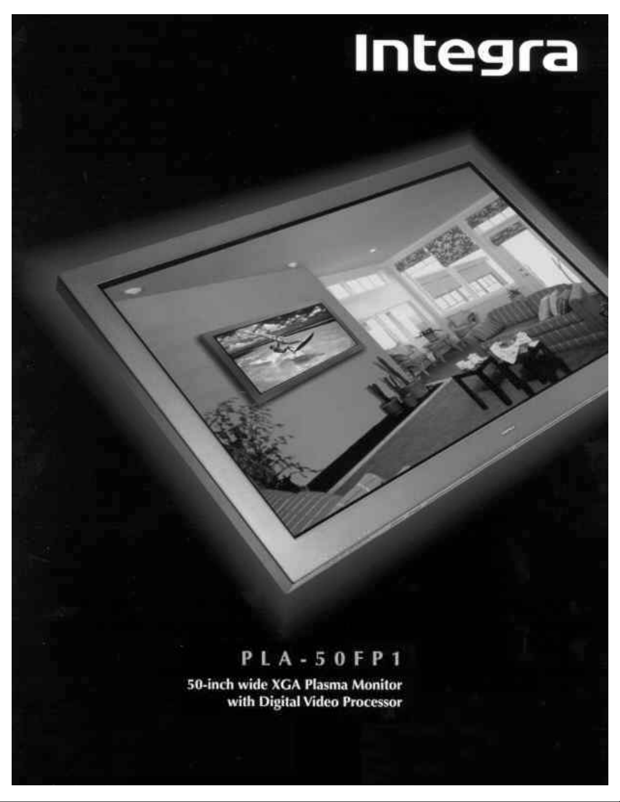
Page 1
Page 2
Page 3
USE THIS SERVICE MANUAL WHEN SERVICING
Model PLA-50V1
Page 4

CONTENTS
SAFETY PRECAUTIONS .................................................................................................................................. 2-1
USERS MANUAL............................................................................................................................................... 3-1
TROUBLESHOOTING ....................................................................................................................................... 4-1
METHOD OF ADJUSTMENTS .......................................................................................................................... 5-1
CIRCUIT DESCRIPTION ................................................................................................................................... 6-1
METHOD OF DISASSEMBLY ........................................................................................................................... 7-1
PACKAGING...................................................................................................................................................... 8-1
PARTS LIST....................................................................................................................................................... 9-1
CONNECTION DIAGRAMS............................................................................................................................. 10-1
BLOCK DIAGRAMS......................................................................................................................................... 11-1
SCHEMATIC DIAGRAMS................................................................................................................................ 12-1
1-1
Page 5
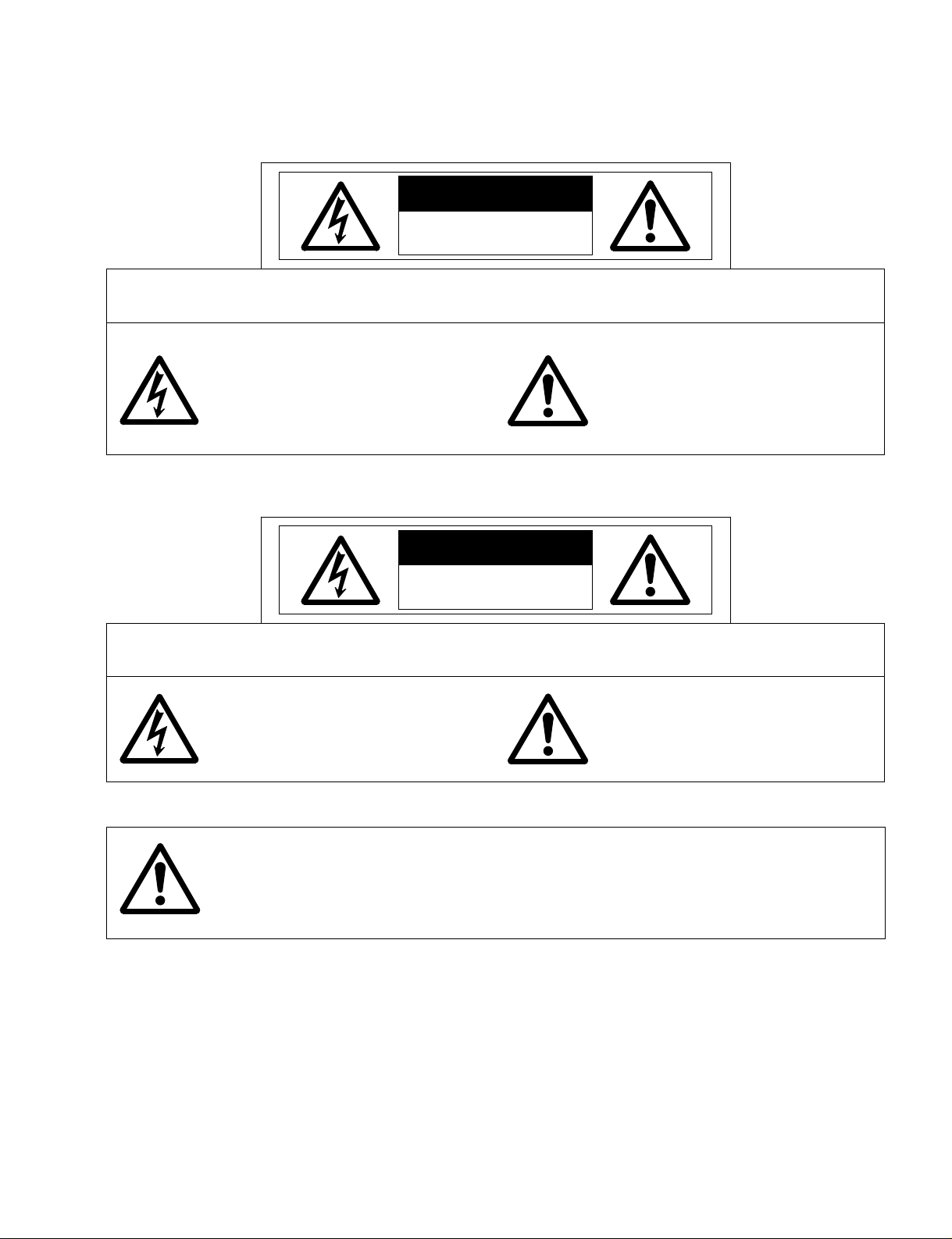
SAFETY PRECAUTIONS
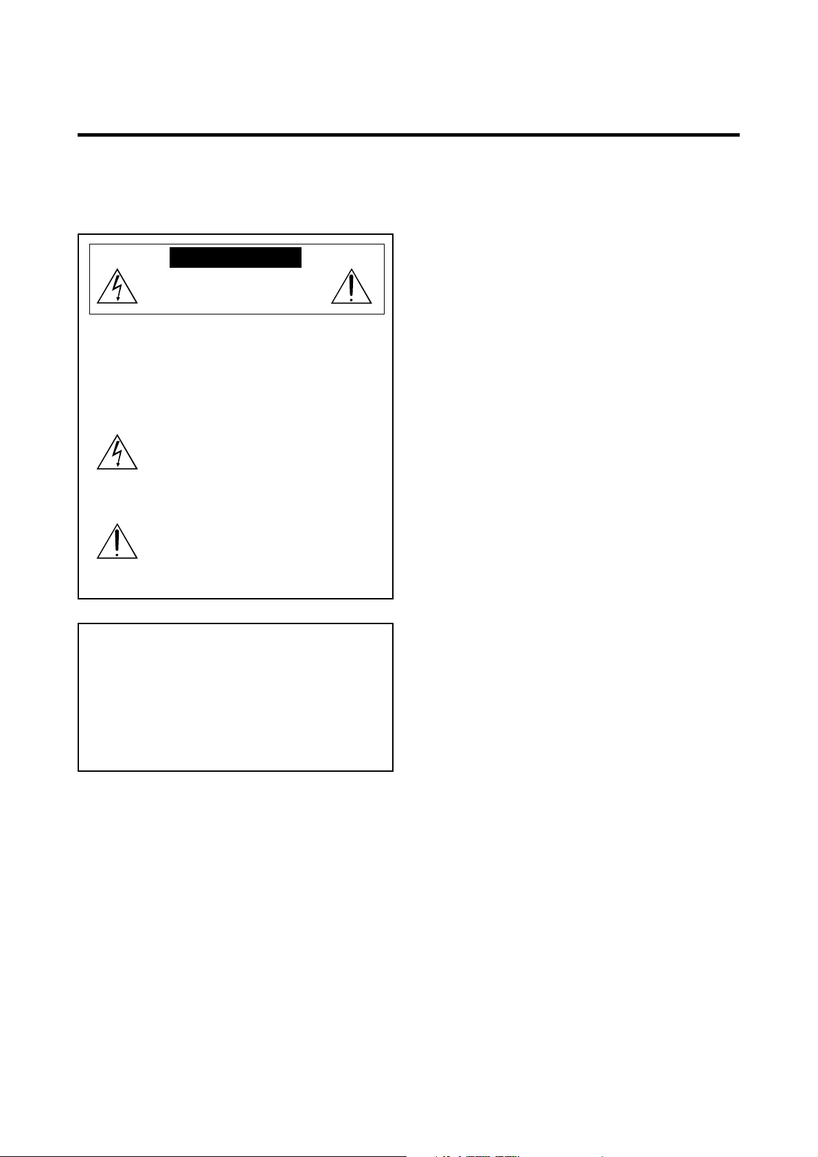
CAUTION
RISK OF ELECTRIC SHOCK
DO NOT OPEN
CAUTION: TO REDUCE THE RISK OF ELECTRIC SHOCK, DO NOT OPEN REAR COVER. NO USER-SERVICEABLE
PARTS INSIDE. REFER SERVICING TO QUALIFIED SERVICE PERSONNEL.
This symbol warns the user that uninsulated voltage within the unit may have
sufficient magnitude to cause electric
shock. Therefore, it is dangerous to make
any kind of contact with any part inside of
this unit.
This symbol alerts the user that important
literature concerning the operation and
maintenance of this unit has been
included.
Therefore, it should be read carefully in
order to avoid any problems.
ATTENTION
RISQUE D'ELECTROCUTION
NE PAS OUVRIR
ATTENTION: POUR EVITER LES RISQUES D' ELECTROCUTION, NE PAS ENLEVER LE CONVERCLE ARRÈRE. AUCUN DES
ELEMENTS INTERNES NE DOIT ETRE REPARE PAR L'UTILISATEUR. NE CONFIER L' ENTRETIEN QU'A UN
PERSONNEL QUALIFIE.
L'éclair fléché dans un triangle équilatéral est
destiné à avertir l'utilisateur de la présence,
dans l'appareil, d'une zone non-isolée soumise
à une haute tension dont l'intensité est suffisante pour constituer un risque d'électrocution.
Le point d'exclamation dans un triangle équilatéral est destiné à attirer l' attention de l'utilisateur sur la présence d'informations de
founctionnement et d'entretien importantes dans
la brochure accompagnant l'appareil.
WARNING
HEATSINK MAY BE ENERGIZED.
TEST BEFORE TOUCHING.
2-1
Page 6
SAFETY PRECAUTIONS
1. Before returning an instrument to the customer, al-
ways make a safety check of the entire instrument, in-
cluding, but not limited to, the following items.
a. Be sure that no built-in protective devices are
defective and/or have been defeated during
servicing. (1) Protective shields are provided on
this chassis to protect both the technician and
the customer. Correctly replace all missing protective shields, including any removed for servicing convenience. (2) When reinstalling the
chassis and/or other assembly in the cabinet, be
sure to put back in place all protective devices,
including,but not limited to, nonmetallic control
knobs,insulating fishpapers,adjustment and
compartment covers/shields, and isolation resistor/capacitor networks. Do not operate this
instrument or permit it to be operated without all protective devices correctly installed
and functioning.
b. Be sure that there are no cabinet openings
through which an adult or child might be able to
insert their fingers and contact a hazardous voltage. Such opening include,but are not limited to,
(1) spacing between the picture tube and the
cabinet mask, (2) excessively wide cabinet ventilation slots, and (3) an improperly fitted and/or
incorrectly secured cabinet back cover.
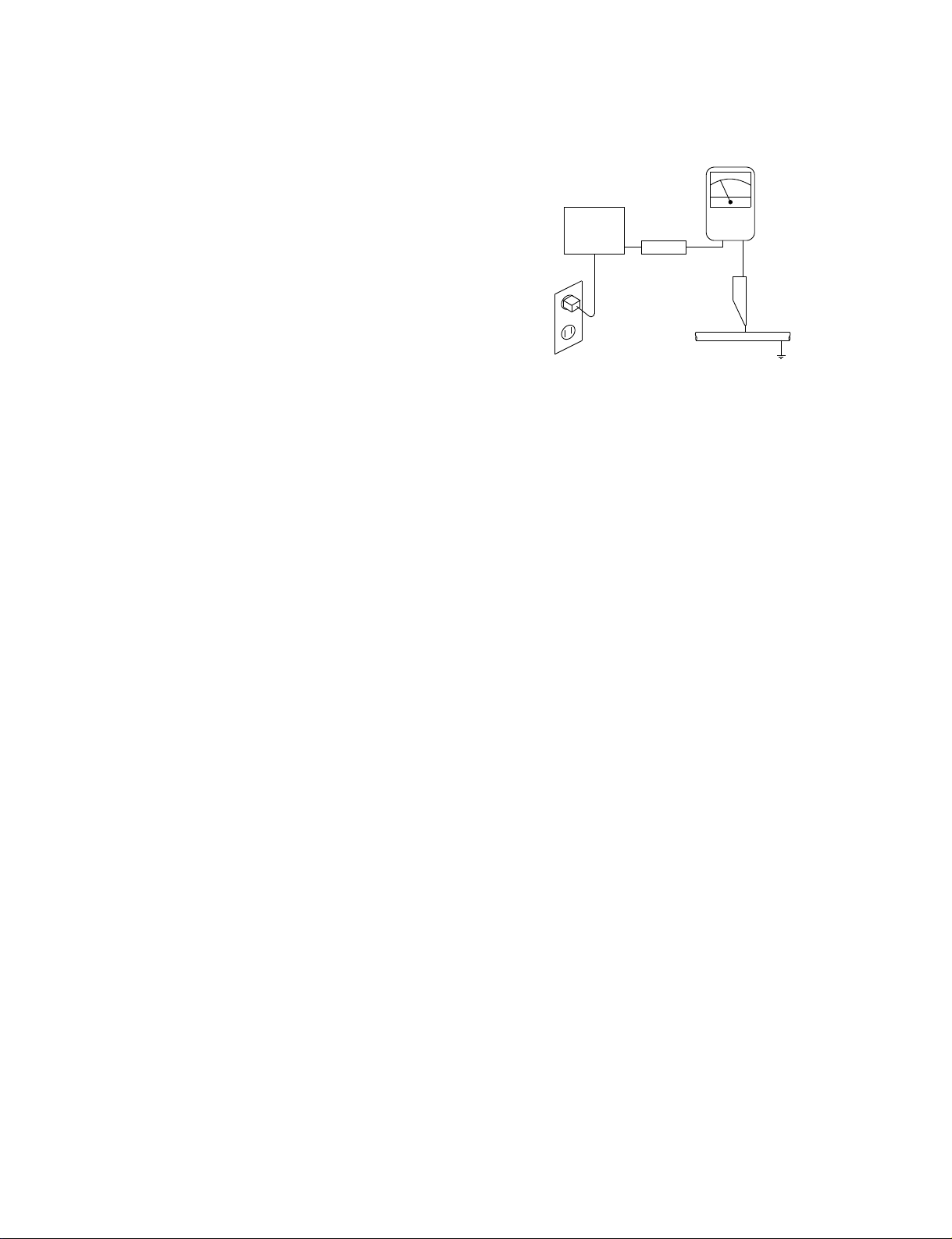
c. Leakage Current Hot Check — With the instru-
ment completely reassembled,plug the AC line
cord directly into a 240V AC outlet. (Do not use
an isolation transformer during this test.) Use a
leakage current tester or a metering system that
complies with American National Standards Institutes (ANSI) C101.1 Leakage Current for Appliances and Underwriters Laboratories(UL)
1950. With the instrument AC switch first in the
ON position and then in the OFF position, measure from a known earth ground (metal
waterpipe, conduit,etc.) to all exposed metal
parts of the instrument(antennas, handle
bracket, metal cabinet, screwheads, metallic
overlays, control shafts,etc.), especially any exposed metal parts that offer an electrical return
path to the chassis. Any current measured must
not exceed 3.5 milliamp. Reverse the instrument power cord plug in the outlet and repeat
test.ANY MEASUREMENTS NOT WITHIN
THE LIMITS SPECIFIED HEREIN INDICATE A
POTENTIAL SHOCK HAZARD THAT MUST
BE ELIMINATED BEFORE RETURNING THE
INSTRUMENT TO THE CUSTOMER.
AC Leakage Test
(READING SHOULD
NOT BE ABOVE
DEVICE
UNDER
TEST
TEST ALL
EXPOSED METAL
SURFACES
3-WIRE CORD
ALSO TEST WITH
PLUG REVERSED
(USING AC ADAPTER
PLUG AS REQUIRED)
LEAKAGE
CURRENT
TESTER
+–
3.5 mA)
EARTH
GROUND
2. Read and comply with all caution and safety-related
notes on or inside the Monitor cabinet, on the Projection Monitor chassis, or on the picture tube.
3. Design Alteration Warning — Do not alter or add
to the mechanical or electrical design of this unit.
Design alterations and additions, including, but not
limited to, circuit modifications and the addition of
the items such as auxiliary audio and/or video output connections might alter the safety characteristics of this Monitor and create a hazard to the user.
Any design alterations or additions will void the
manufacturer's warranty and will make you,the
servicer,responsible for personal injury or property
damage resulting therefrom.
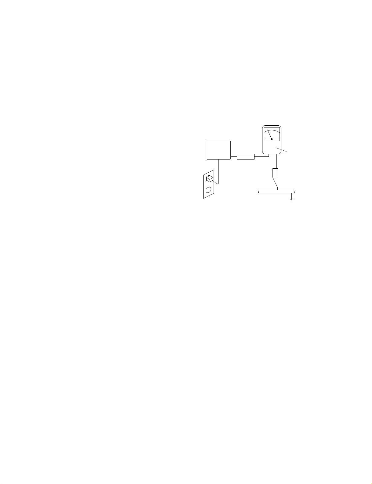
4. Hot Chassis Warning — a. Some MultiSync Monitor
chassis are electrically connected directly to one
conductor of the AC power cord and may be safely
serviced without an isolation transformer only if the
AC power plug is inserted so that the chassis is
connected to the ground side of the AC power
source. To confirm that the AC power plug is inserted correctly, with an AC voltmeter measure between the chassis and a known earth ground. If a
voltage reading in excess of 1.0V is obtained, remove and reinsert the AC power plug in the opposite polarity and again measure the voltage potential between the chassis and a known earth ground.
b. Some Plasma chassis normally have 85V AC
(RMS), between chassis and earth ground regardless of the AC plug polarity. These chassis can be
safely serviced only with an isolation transformer
inserted in the power line between the receiver and
the AC power source, for both personnel and test
equipment protection. c. Some Plasma chassis
have a secondary ground systems in addition to the
main chassis ground. This secondary ground system is not isolated from the AC power line. The two
ground system are electrically separated by insulating material that must not be defeated or altered.
2-2
Page 7

SAFETY PRECAUTIONS
5. Observe original lead dress. Take extra care to
assure correct lead dress in the following areas:
a. near sharp edges, b. near thermally hot parts—
be sure that leads and components do not touch
thermally hot parts, c. the AC supply, d. high voltage, and e. antenna wiring. Always inspect in all
areas for pinched, out-of-place, or frayed wiring. Do
not change spacing between components, and between components and the printed-circuit board.
Check AC power cord for damage.
6. Components,parts, and/or wiring that appear to
have overheated or are otherwise damaged should
be replaced with components, parts, or wiring that
meet original specifications. Additionally,determine
the cause of overheating and/or damage and, if
necessary, take corrective action to remove any
potential safety hazard.
7. PRODUCT SAFETY NOTICE —Many MultiSync
Monitor electrical and mechanical parts have spe-
cial safety-related characteristics some of which
are often not evident from visual inspection, nor
can the protection they give necessarily be obtained by replacing them with components rated
for higher voltage, wattage, etc. Parts that have
special safety characteristics are identified in this
service data by shading with a mark on schematics and by shading or a mark in the parts list. Use
of a substitute replacement part that does not have
the same safety characteristics as the recommended replacement part in this service data parts
list might create shock, fire, and/or other hazards.
2-3
Page 8
PRECAUTIONS DE SECURITE
1. Avant de remettre un appareil à un client, faire
toujours d'abord un examen de sécurité de
l'appareil en entier comprenant, mais ne s'y limitant
pas les points cités ci-dessous:
a. Vérifier qu' aucun des dispositifs de protection ne
soit défectueux ou n' ait été endommagé pendant
les travaux.
(1) Les volets protecteurs sur ce châssis ont été
montés pour protéger aussi bien le technicien
que le client. Remplacer correctement tous les
volets protecteurs manquants, aussi bien que
ceux qui ont pu être enlevés pour la commodité
des travaux.
(2) Quand vous remettez le châssis ou d'autres
assemblages ensemble dans le coffret, vérifier
qu' ont été remis à leur place tous les dispositifs
de protection, comprenant mais ne s' y limitant
point, les boutons de contrôle non-métalliques,
les feuilles d'isolation, les couverture/volets de
l'ajustement et du compartiment, et l'isolation des
réseaux résistance/condensateur. Ne pas
travailler sur cet appareil ni permettre qu'y
soit effectué un travail sans que tous les
dispositifs de protection n' y soient
correctement installés fonctionnants.
b. Bien vérifier qu'il n'y ait aucune ouverture sur le
coffret qui ne puisse permettre à un adulte ou à
un enfant d'y faire pénétrer ses doigts et attraper
une décharge électrique.
De telles ouvertures comprendraient sans pour
autant s'y limiter (1) l'espace entre le tube à images et le coffret de l'eppareil, (2) les espaces
excessivement ouverts pour la ventilation et (3) la
couverture arrière du coffret improprement fixée
ou incorrectement protegée.
c. Vérification de courant de fuite
L'appareil ayant été complètement réassemblé,
brancher-le à une prise de courant de 240V. (Ne pas se
servir d'un transformateur
d'isolation pendant ce
test). Se servir d'un vérificateur de courant
d'excitation ou d'un système de mesure conforme
aux normes ANSI (American National Standards
Institute) C101.1 Leakage Current for Appliances
et U. L (Underwriters Laboratories) 1950. Le bouton de l'appareil en position "Marche" et ensuite
en position "Arrêt", mesurer à partir d'une prise
de terre (métallique tuyauterie, conduite, etc...) à
toutes les pièces métalliques de l'appareil
exposées (antennes, poignet métalliques, coffren
métallique, tête des vis, surfaces métalliques,
traits de contrôle, etc.) surtout à toutes les pièces
métalliques exposées qui peuvent reconduire le
courant au châssis. En aucun cas, la mesure du
courant ne doit dépasser 3.5 milliamp. Inverser la
fiche de courant de l'appareil dans la prise et
répéter le test. Tout mesurage ne s'arrêtant
pas aux limites spécifiées icicomporte un risque de décharge électrique dangereux, qui
doit être éliminé, avant que l'appareil ne soit
remis au client.
EXAMEN DE COURANT
D'EXCITATION
(LA MESURE DU COURANT
NE DOIT PAS DEPASSER
3.5 MILLIAMP)
DISPOSIT IF
SOUS
L ' EXAMEN
EXAMINER TOUTES
LES PIECES METALLIQUES
DEL' APPAREIL EXPOSEE
3-CORDES DE FIL
EXAMINER AVEC
LA FICHE DE COURANT
INVERSEE
(SE SERVIR DE LA FICHE DE COURANT
DE L' A DAPTATEUR COMME DEMANDEE)
+–
VERIFICATEUR
DE CORANT
DE FUITE
PRISE DE TERRE
2. Lire et respecter toutes les mises en garde et notes
de sécurité à l'intérieur ou à l'extérieur du coffret du
rétro-projecteur, sur le châssis du rétro-projecteur
ou sur le tube à images.
3. Mise en garde contre la modification du dessin
Ne pas modifier ni ajouter à la pièce mécanique ou
électrique du modèle. Des modifications ou additions, comportant, mais ne s'y limitant pas, des
modifications des circuits et l'addition d'éléments
tels que des auxilliairs audio et/ou des
branchements pour la prise de vidéo, pourrait
éprouver la sécurité de ce rétro-projecteur et créer
un risque pour l'utilisateur. Tout changement ou addition accomplie annulera la garantie du fabricant et
va rendre votre service d'entretien, responsable des
dommages corporels ou de biens en résultant.
4. Mise en garde contre le châssis sous tension
a. Certains châssis de rétro-projecteur sont
électriquement reliés à un conducteur du fil de
courant et ainsi peuvent ne comporter aucun risque sans un transformateur d'isolation seulement
si la prise de courant est branchée, de manière
que le châssis est relié à la prise de terre de la
source de courant. Pour s'assurer que la prise de
courant est correctement insérée, relever les
mesures avec un voltmètre de courant entre le
châssis et un point de prise de terre bien connu.
Si le voltage indiqué est supérieur à 1,0V,
débrancher et reinsérer la prise de courant dans
la polarité contraire et une fois de plus remesurer
le voltage potentiel entre le câssis et la prise de
terre.
2-4
Page 9

PRECAUTIONS DE SECURITE
b. Certains châssis de moniteur ont habituellement
85V (RMS) entre le châssis et la prise de terre, en
fonction de la polarité de la prise de courant. Ces
châssis peuvent ne comporter aucun risque
seulement avec un transformateur d'isolation
inséré dans la ligne de puissance située entre de
rétro-projecteur et la source d'électricité, cela
pour la protection aussi bien du personnel que du
matériel de vérfication.
c. Certains châssis de rétro-projecteur ont un
système secondaire de masse en addition avec
le système principal de masse du châssis. Ce
système secondaire de masse n'est pas isolé du
courant électrique. Les deux systèmes sont
électriquement séparés par du matériel
d'isolation qu' on vérifiera bien qu'il ne soit ni
altéré ni défectueux.
5. Vérifier la couverture originale en plomb. Accorder
la plus grande attention à la couverture de plomb
notamment aux endroits ci-dessous indiqués.
a. Près des bords aigus
b. près des parties très chaudes
Vérifier que les composants et les plombs ne
touchent pas les parties très chaudes telles que:
c. l'alimentation du courant
d. la haute tension
e. Ies fils de l'antenne
Pousser l'inspection, à tous les endroits, à la recherche des cordes pincées, déplacées ou effilochées.
Ne pas changer l'écartement entre composants, et
entre composants et le tableau de circuit imprimé.
Vérifier que le fil de conduite électrique est en bon
état.
6. Les composants, parts (pièces) et/ou fils qui ont été
trouvés surchauffés devraient être remplacés avec
les composants, pièces et fils s'y reliant avec d'autre
qui ont les mêmes spécifications que les originales.
De plus, rechercher la cause du surchauffement et/
ou des dommages et si nécessaire, prendre les
mesures propres pour prévenir tout risque potentiel.
7. Note sur sûreté de l'appareil
Beaucoup de pièce de rétro-projecteur, qu'elles
soient électriques ou mécaniques, ont des dispositions de sécurité qui ne sont pas toujours évidentes
d'une simple inspection visuelle et la protection
qu'elles donnent nécessairement ne pourront être
pas obtenues par les remplaçants avec des
composants aux voltages ou watts plus élevés.
Les pièces qui ont des caractéristiques particulières
de sécurité sont identifiées avec un trait marqué
sur les schémas et sont ombragés ou comportent
un trait sur la liste des pièces. L'utilisation d'un
produit substitutif qui n'aurait pas les mêmes
caractéristiques comme il est recommandé dans
ces données d'entretien pourrait provoquer une
décharge électrique, un feu, et/ou d'autres dangers.
2-5
Page 10

SAFETY PRECAUTIONS
1 . Cautions for disassembly
(1)For the suspension-type set (No. of workers: 3
to 5 including assistants)
• Take adequate measures in order not to damage the surface of the set or the filter, using a
protection mat (vinyl sheet or blanket).
• When relieving the set from the condition of
suspension from the ceiling, do not tilt its main
body too much by supporting its both sides,
while the mounting hooks (top and bottom) are
released. (Reasons: If the main body is positioned slantwise, a load is applied to its upper
part and there can be danger of making the
set fall down carelessly when the set is unhooked.)
• During disassembly, the allocation of personnel should be such that suitable stands or platforms are assuredly arranged to enable the
personnel to support the set, standing on both
sides of the set. For safety, it is preferable to
provide for assistant personnel who can receive
the removed set.
• During this removal work, support the set at its
frame with hands. Never touch the filter or glass
surface. Assistant personnel on the front side
should apply hands to the lower part of the
casing. [If the casing is strongly hit with a
wooden hammer or the like, the unseen side
area of the module panel glass may be broken
even though the module itself does not seem
to have been broken . Therefore , support the
frame by hand in order not to drop it.]
2.
The least minimum caut ions for product disassembly
• Secure a working space, arranged as wide as possible.
• Prior to disassembling the set, protect the acrylic
surface with an air mat or the like.
• To prevent the thread ridges from being damaged,
use an adequate screwdriver.
• Many screws are actually used. Therefore, use
two or three containers where these screws can
be kept . Never disassemble the inner parts of the
module (pipes, etc.).
• When lifting the module from the set, two persons
should stand on both sides of the module to hold
the stable parts of the junction while they lift the
module upright. (If dust or such foreign substance
enters in between the module and the filter, moir*
or similar problems can arise. In addition, once it
enters, it is necessary to take careful measures
not to damage the contamination area while removing contaminants.) [Please understand that the
replacement of the module may call for an air-blast
treatment (air brush) in a clean room.]
Complementary caution) In particular, if a conductive foreign matter (such as a metallic chip) is attached to the flexible cable of the module, there
can be danger of the occurrence of a phenomenon like wire breakage that is caused by partition breakdown in the module. For this reason, it
is necessary to bear in mind that the flow of air
blast should be directed only in the predetermined
direction at all times.
(2)For the wall-hang type, corner type, or pole unit
mounting set (No. of workers: 2 <generally>)
• Examining a good timing, release the mounting hooks (top and bottom) from the right and
the left.
• If the set is installed in an elevated place, provide for firm scaffolds in advance. It is preferable to ask for the support of assistant personnel as in the case of the suspension type.
• During this removal work, try to support the set
at its frame with hands. Never touch the filter
or glass surface. Assistant personnel on the
front side should apply hands to the lower part
of the casing. [If the casing is strongly hit with
a wooden hammer or the like, the unseen side
area of the module panel glass may be broken
even though the module itself does not seem
to have been broken. Therefore, support the
frame by hand in order not to drop it.]
3. Method of returning the set (when returning the
set to the manufacturing base in Japan)
• When returning the set, put the set in the speci-
fied package box.
Otherwise, swinging and vibration Ioads may be
applied to the set during transportation, and this
may give rise to destruction of a mounting section, such as gas-hermetically-sealed pipe (glass)
of the moduIe.
• When optional parts are also put in the box for
returning, a list of options (accessories) should also
be produced and returned, if possible. This arrangement is effective to confirm the owner of the
returned items.
• To confirm the user-oriented problem, and for the
purpose of future improvements, a report of reasons for malfunction should also be packed.
A definite address should be specified so that the
repaired set can be returned and faulty phenomena can be confirmed .
2-6
Page 11

SAFETY PRECAUTIONS
(Notes)
The component by the name of “module” used in
this product is defined as a section that is provided with a digital circuit board (including highvoltage parts) used to emit light in the glass panel
part, excluding the surface acrylic fiIter or the tempered glass fiIter. It must be noted that it does
never mean the glass panel part only.
2-7
Page 12

PlasmaSync Plasma Monitor
User’s Manual
NEC Technologies
Page 13
Important Information
Precautions
Please read this manual carefully before using your NEC
plasma monitor and keep the manual handy for future
reference.
CAUTION
RISK OF ELECTRIC SHOCK
DO NOT OPEN
CAUTION:
TO PREVENT FIRE OR SHOCK HAZARDS, DO NOT EXPOSE
THIS UNIT TO RAIN OR MOISTURE. ALSO DO NOT USE
THIS UNIT’S POLARIZED PLUG WITH AN EXTENSION CORD
RECEPTACLE OR OTHER OUTLETS, UNLESS THE
PRONGS CAN BE FULLY INSERTED. REFRAIN FROM
OPENING THE CABINET AS THERE ARE HIGH-VOLTAGE
COMPONENTS INSIDE. REFER SERVICING TO QUALIFIED
SERVICE PERSONNEL.
TO REDUCE THE RISK OF ELECTRIC
SHOCK, DO NOT REMOVE COVER. NO
USER-SERVICEABLE PARTS INSIDE.
REFER SERVICING TO QUALIFIED
SERVICE PERSONNEL.
This symbol warns the user that uninsulated
voltage within the unit may have sufficient
magnitude to cause electric shock.
Therefore, it is dangerous to make any kind
of contact with any part inside of this unit.
This symbol alerts the user that important
literature concerning the operation and
maintenance of this unit has been included.
Therefore, it should be read carefully in
order to avoid any problems.
WARNING
WARNING
This is a Class A product. In a domestic environment, this
product may cause radio interference in which case the user
may be required to take adequate measures.
Warnings and Safety Precaution
The NEC plasma monitor is designed and
manufactured to provide long, trouble-free service.
No maintenance other than cleaning is required. Use
a soft dry cloth to clean the panel. Never use
solvents such as alcohol or thinner to clean the panel
surface.
The plasma display panel consists of fine picture
elements (cells). Although NEC produces the plasma
display panels with more than 99.99 percent active
cells, there may be some cells that do not produce
light or remain lit.
For operating safety and to avoid damage to the unit,
read carefully and observe the following instructions.
To avoid shock and fire hazards:
1. Provide adequate space for ventilation to avoid internal
heat build-up. Do not cover rear vents or install the unit
in a closed cabinet or shelves.
The unit is equipped with cooling fans. If you install
the unit in an enclosure, make sure there is adequate
space at the top of the unit to allow hot air to rise and
escape. If the monitor becomes too hot, the overheat
protector will be activated and the monitor will be turned
off. If this happens, turn off the power to the monitor and
unplug the power cord. If the room where the monitor is
installed is particularly hot, move the monitor to a cooler
location, and wait for the monitor to cool for 60 minutes.
If the problem persists, contact your NEC dealer for
service.
2. Do not use the power cord polarized plug with extension
cords or outlets unless the prongs can be completely
inserted.
3. Do not expose the unit to water or moisture.
4. Avoid damage to the power cord, and do not attempt to
modify the power cord.
5. Unplug the unit during electrical storms or if the unit
will not be used over a long period.
6. Do not open the cabinet which has potentially dangerous
high voltage components inside. If the unit is damaged in
this way the warranty will be void. Moreover, there is a
serious risk of electric shock.
7. Do not attempt to service or repair the unit. NEC is not
liable for any bodily harm or damage caused if unqualified
persons attempt service or open the back cover. Refer
all service to authorized NEC Service Centers.
Page 14
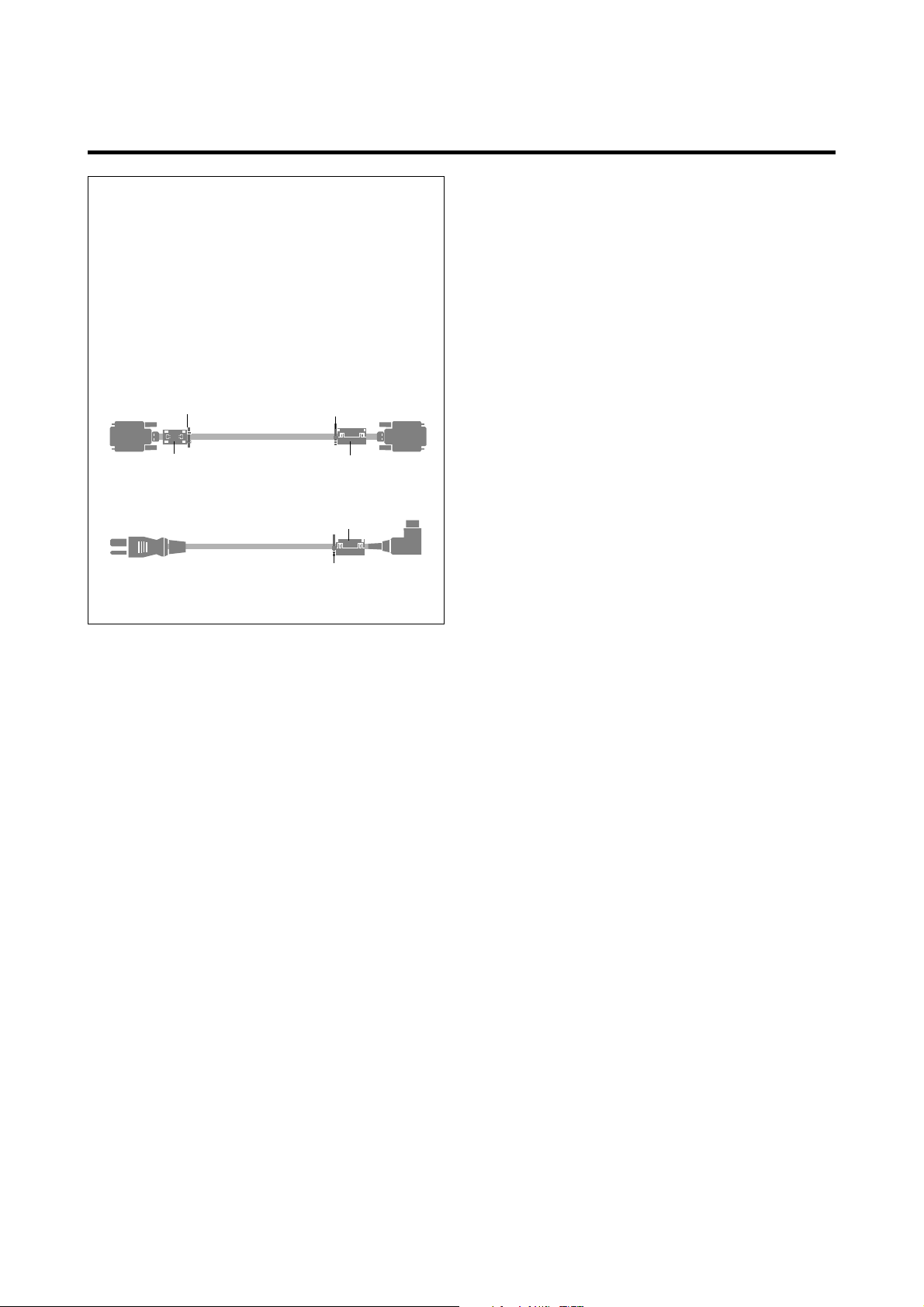
NOTE:
When you connect a computer to this monitor, attach
the supplied ferrite cores. If you do not do this, this
monitor will not comform to mandatory CE or C-Tick
standards.
Attaching the ferrite cores:
Set the ferrite cores on both ends of the DVI cable (not
supplied), and one end of the power cable (supplied).
Close the lid tightly until the clamps click.
Use the band to secure the ferrite core (supplied).
DVI cable (not supplied)
band
core (small)
Power cable (supplied)
band
band
(Plasma Monitor side)
Connector
core (small)
core (large)
Set side
To avoid damage and prolong operating life:
1. Use only with 100-240V 50/60Hz AC power supply.
Continued operation at line voltages greater than 100240 Volts AC will shorten the life of the unit, and might
even cause a fire hazard.
2. Handle the unit carefully when installing it and do not
drop.
3. Set the unit away from heat, excessive dust, and direct
sunlight.
4. Protect the inside of the unit from liquids and small
metal objects. In case of accident, unplug the unit and
have it serviced by an authorized NEC Service Center.
5. Do not hit or scratch the panel surface as this causes
flaws on the surface of the screen.
6. For correct installation and mounting it is strongly
recommended to use a trained,authorized NEC dealer.
7. As is the case with any phosphor-based display (like a
CRT monitor, for example) light output will gradually
decrease over the life of a Plasma Display Panel.
Recommendations to avoid or minimize phosphor burn-in
Like all phosphor-based display devices and all other gas
plasma displays, plasma monitors can be susceptible to
phosphor burn under certain circumstances. Certain
operating conditions, such as the continuous display of a
static image over a prolonged period of time, can result in
phosphor burn if proper precautions are not taken. To protect
your investment in this NEC plasma monitor, please adhere
to the following guidelines and recommendations for
minimizing the occurrence of image burn:
* Always enable and use your computer’s screen saver
function during use with a computer input source.
* Display a moving image whenever possible.
* Change the position of the menu display from time to time.
* Always power down the monitor when you are finished
using it.
If the plasma monitor is in long term use or continuous
operation take the following measures to reduce the
likelihood of phosphor burn:
* Lower the Brightness and Contrast levels as much as
possible without impairing image readability.
* Display an image with many colors and color gradations
(i.e. photographic or photo-realistic images).
* Create image content with minimal contrast between light
and dark areas, for example white characters on black
backgrounds. Use complementary or pastel color whenever
possible.
* Avoid displaying images with few colors and distinct,
sharply defined borders between colors.
Contact an NEC affiliate or authorized dealer for other
recommended procedures that will best suit your particular
application needs.
Page 15

Contents
How to Attach Options to the Plasma Monitor .. E-1
Introduction ................................................... E-2
Introduction to the PlasmaSync 50MP1
Plasma Monitor..................................................... E-2
The features you’ll enjoy include:............................. E-2
Contents of the Package ......................................... E-2
Options ............................................................... E-2
Part Names and Function ................................ E-3
Front View ........................................................... E-3
Rear View / Terminal Board ................................... E-4
Remote Control Unit .............................................. E-5
Battery Installation and Replacement ....................... E-6
Using the wired remote control mode ...................... E-7
Operating Range .................................................. E-7
Handling the remote control unit ............................. E-7
Installation .................................................... E-8
Connecting Your PC or Macintosh Computer ............ E-9
Connections with Equipment that has
a Digital Interface .............................................. E-9
Connecting Your Document Camera ........................ E-9
Connecting Your VCR or Laser Disc Player................ E-9
Connecting Your DVD Player .................................. E-9
External Speaker Connections ...............................E-10
Pin Assignments and Signal Levels
for 15 pin RGB (Analog) .......................................E-11
Pin Configuration and Signal
of the RGB 3 IN Connector (DVI Connector) ............ E-11
Basic Operations ........................................... E-12
POWER ..............................................................E-12
To turn the unit ON and OFF: ................................ E-12
VOLUME ............................................................ E-12
To adjust the volume: ............................................. E-12
MUTE ................................................................. E-12
To cancel the sound:............................................... E-12
DISPLAY ..............................................................E-12
To check the settings: ............................................. E-12
DIGITAL ZOOM ................................................... E-12
AUTO ADJUST .................................................... E-12
To adjust the size or quality of the picture
automatically: ........................................................ E-12
OFF TIMER ..........................................................E-13
To set the off timer: ................................................ E-13
To check the remaining time: ................................. E-13
To cancel the off timer ........................................... E-13
OSM Controls ................................................ E-17
Menu Operations ................................................. E-17
Picture Settings Menu ............................................E-19
Adjusting the picture .............................................. E-19
Setting the picture mode according to the
brightness of the room ........................................... E-20
Setting the color temperature ................................. E-21
Adjusting the color to the desired quality ............... E-22
Reducting noise in the picture ................................ E-23
Sound Settings Menu ............................................E-24
Adjusting the treble, bass and left/right balance ..... E-24
Screen Settings Menu ........................................... E-25
Adjusting the Position, Size, Fine Picture,
Picture Adj ............................................................. E-25
Function Settings Menu .........................................E-26
Setting the on-screen display .................................. E-26
Adjusting the position of the menu display ............ E-27
Setting the power management
for computer images .............................................. E-28
POWER/STANDBY indicator ............................... E-29
Setting the gray level for the sides of the screen ..... E-30
Setting the picture to suit the movie ....................... E-30
Setting RGB3 ADJ................................................. E-31
Reducing burn-in of the screen .............................. E-31
Resetting to the default values ................................ E-32
Option Settings Menu ...........................................E-33
Setting the allocation of the audio connectors ........ E-33
Setting the BNC connectors ................................... E-33
Setting a computer image to the correct RGB
select screen ......................................................... E-34
Setting high definition images to the suitable
screen size ............................................................ E-35
Setting the picture size for RGB input signals ........ E-36
Information Menu ................................................E-36
Checking the frequencies, polarities of input signals,
and resolution ........................................................ E-36
Setting the language for the menus ......................... E-37
Setting the video signal format ............................... E-37
External Control ...........................................E-39
Table of Signals Supported ............................ E-47
Supported resolution ............................................E-47
Troubleshooting............................................ E-49
Specifications ............................................... E-50
WIDE Operations ........................................... E-14
Watching with a wide screen (manual) ...................E-14
When watching videos or digital video discs .......... E-14
When watching high definition video source ......... E-14
Watching computer images with a wide screen ....... E-15
When “PICTURE SIZE” is set to “OFF” ............... E-15
MULTI SCREEN Operations ..............................E-16
Showing a couple of pictures on the screen
at the same time .................................................E-16
Selecting the input signals to be displayed ............. E-16
Adjusting the OSM controls .................................. E-16
Page 16
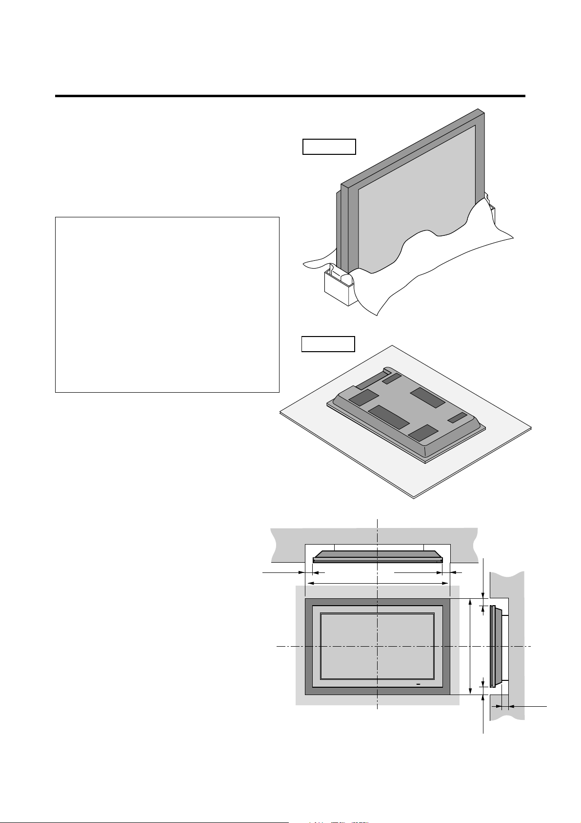
How to Attach Options to the Plasma Monitor
Drawing B
50mm (2")
1240
mm
(48.8")
766
mm
(30.2")
50mm (2")
50
mm
(2") 50
mm
(2")
Wall
Wall
50mm (2")
You can attach your optional mounts or stand to the plasma
monitor in one of the following two ways:
* While it is upright. (See Drawing A)
* As it is laid down with the screen face down (See Drawing
B). Lay the protective sheet, which was wrapped around
the monitor when it was packaged, beneath the screen
surface so as not to scratch the screen face.
• This device cannot be installed on its own.
Be sure to use a stand or original mounting
unit. (Wall mount unit, Stand, etc.)
* See page E-2.
• For correct installation and mounting it is
strongly recommended to use a trained,
authorized NEC dealer.
Failure to follow correct mounting
procedures could result in damage to the
equipment or injury to the installer.
Product warranty does not cover damage
caused by improper installation.
Drawing A
Ventilation Requirements for
enclosure mounting
To allow heat to disperse, leave space between
surrounding objects as shown on the diagram
below when installing.
E-1
Page 17

Introduction
Introduction to the PlasmaSync 50MP1 Plasma Monitor
NEC’s PlasmaSync is a seamless blend of cutting-edge
visual technology and sophisticated design. At 50-inches,
with a 16:9 aspect ratio, the PlasmaSync 50MP1 certainly
makes a big impression. However, at a mere 4.2 inches/
107 mm thin, the monitor’s sleek techno-art lines blend in
well with your environment. PlasmaSync’s crisp, vivid
image quality will transform data from any graphic
medium from PCs to DVD players- into art. And weighing
only 101.3 lbs/ 46 kg, it actually can be hung almost
anywhere. NEC has made sure that a host of multimedia
resources can be easily connected and displayed as
brilliantly as intended on the PlasmaSync monitor.
The features you’ll enjoy include:
• 50-inch screen
• 16:9 aspect ratio
• Capsulated Color Filter (CCF) and black matrix
• 4.2 inch / 107 mm thin
• 101.3 lbs/ 46 kg light
• High-resolution screen: 1365768 pixels
• 160-degrees of off-axis viewing, horizontally and
vertically.
• Flicker - and warp - free display provides excellent
image geometry even in screen corners
• Not affected by magnetic fields, no color drift or edge
distortion.
• VGA, SVGA, XGA, SXGA, computer signal
compatibility
• NTSC, PAL, SECAM, composite and S-Video signal
compatibility
• 480P, 1080I, 720P and HDTV signal compatibility
• PCs, VCRs, Laser Disc and DVD player source
compatibility
• AccuBlend scan conversion automatically converts
VGA, SVGA and SXGA signals to the panel’s native
resolution
• RGB input (3*), Video input (3), DVD/HD input (2*),
Audio input (3), External Control input (1)
• AccuColor control system provides user selectable onscreen color temperature settings
• New Drive Technology
• Component video input terminal for DVD, 15.75kHz
(Y, CB, CR )
• Digital broadcasting source compatibitly
• NEC’s OSM menu-driven on screen control system that
makes image adjustments a snap
• Seven languages (English, German, French, Italian,
Spanish, Swedish, and Japanese)
Contents of the Package
PlasmaSync 50MP1 plasma monitor
Power cord
RGB cable (Mini D-Sub 15-pin to Mini D-Sub 15-
pin connector)
Adapter for Macintosh
Remote control unit with two AAA Batteries
User’s manual
Remote cable
Safety metal fittings*
Screws for safety metal fitting*
Ferrite core (small2, large1), band
* These are fittings for fastening the unit to a wall to prevent
tipping due to external shock when using the stand (option).
Fasten the safety fittings to the holes in the back of the
monitor using the safety fitting mount screws.
Options
• Wall mount unit
• Ceiling mount unit
• Tilt mount unit
• Tabletop stand
• Speakers
• Others
* You can select RGB source or Component source for
the 5BNC terminal. When selecting an RGB input, the
source is switched to the RGB input (3); when selecting
a component input, the source is switched to the DVD/
HD input (2).
E-2
Page 18
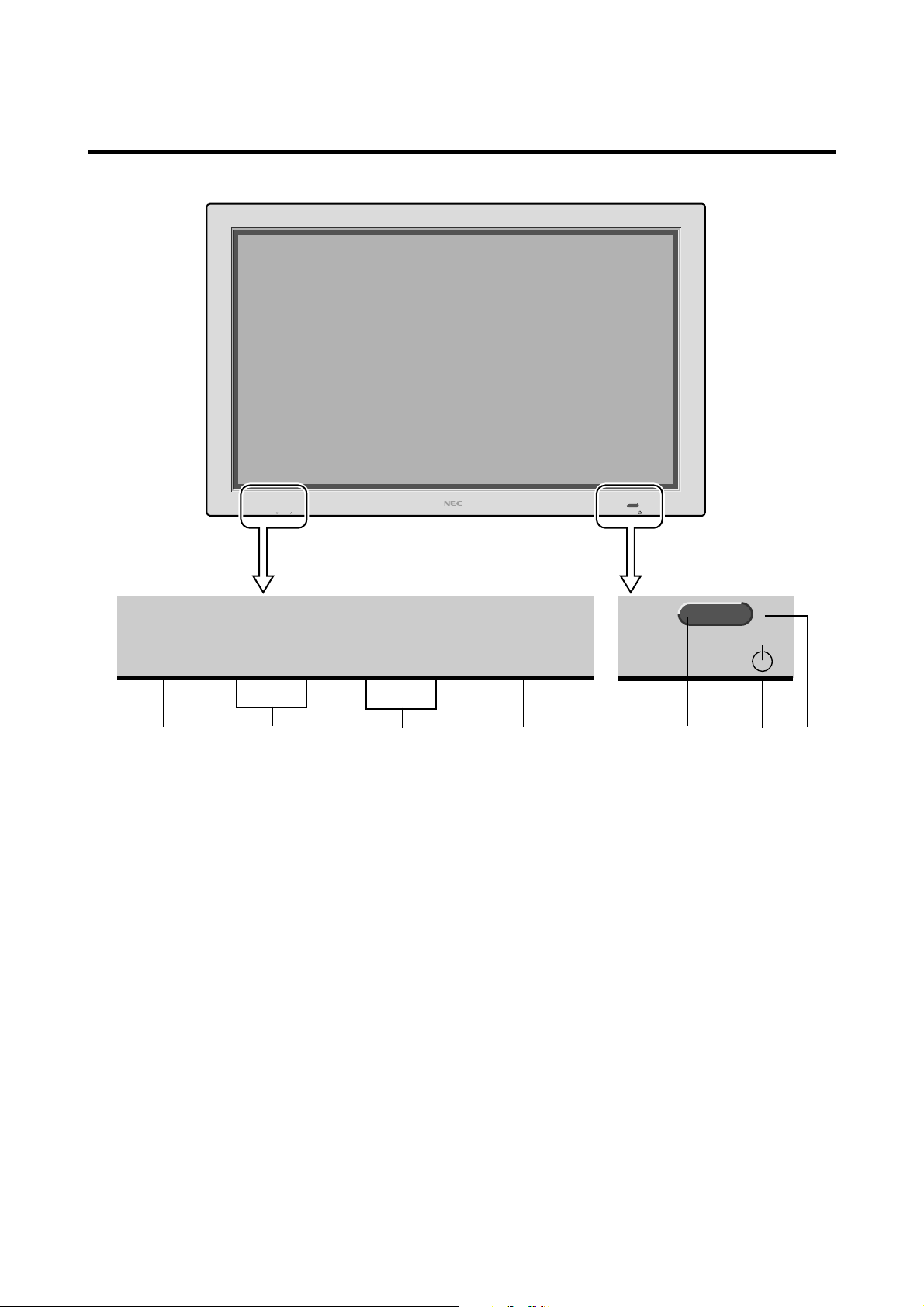
Part Names and Function
Front View
INPUT SELECT VOLUME
PROCEED
VOLUME
DOWN LEFT/– RIGHT/+UP
q PROCEED
Sets the On-Screen Menu (OSM) mode and displays
the main menu.
w VOLUME DOWN and UP
Adjusts the volume. Functions as the CURSOR (▲/
▼) buttons in the On-Screen Menu (OSM) mode.
e LEFT/– and RIGHT/+
Enlarges or reduces the image. Functions as the
CURSOR ( / ) buttons in the On-Screen Menu
(OSM) mode.
POWER/STANDBY
INPUT SELECT
/EXIT
POWER/STANDBY
trewqyu
t POWER/STANDBY indicator
When the power is on ............................. Lights green.
When the power is in the standby mode ... Lights red.
y Power
Turns the monitor’s power on and off.
u Remote sensor window
Receives the signals from the remote control unit.
r INPUT SELECT / EXIT
Switches the input, in the following order:
→ VIDEO1 → VIDEO2 → VIDEO3→ DVD/HD
RGB/PC3 ← RGB/PC2 ← RGB/PC1←
Functions as the EXIT buttons in the On-Screen Menu
(OSM) mode.
E-3
Page 19
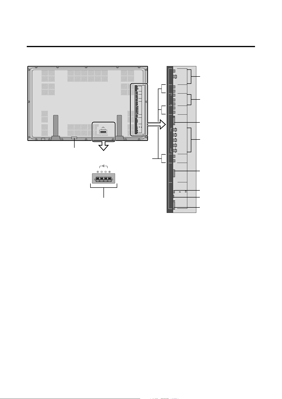
Rear View/ Terminal Board
SPEAKERS MUST
HAVE MORE THAN
7WATT RATING
IMPEDANCE 6 OHM
RIGHT
LEFT
AC IN
K
SPEAKERS MUST
HAVE MORE THAN
7WATT RATING
IMPEDANCE 6 OHM
LEFT
RIGHT
A
AUDIO 1RGB2/ DVD2/ HD2
DVD1/HD1
AUDIO 3 AUDIO 2
CONTROL
LOCK
ON /OFF
VIDEO 1
VIDEO 2
VIDEO 1
VIDEO 2
VIDEO 3
L(MONO)
R
Y
CB/PB
CR/PR
L(MONO)
R
RGB 1
R/CR/PR
G/Y
B/CB/PB
HD
VD
L(MONO)
R
RGB 3
(Digital RGB)
REMOTE
CONTROL
EXTERNAL
CONTROL
J
VIDEO 3
L(MONO)
R
AUDIO 1RGB2/ DVD2/ HD2
Y
CB/PB
DVD1/HD1
CR/PR
L(MONO)
R
RGB 1
R/CR/PR
G/Y
B/CB/PB
HD
VD
L(MONO)
R
AUDIO 3 AUDIO 2
RGB 3
(Digital RGB)
CONTROL
LOCK
ON /OFF
REMOTE
CONTROL
EXTERNAL
CONTROL
B
C
D
E
F
G
H
I
A EXT SPEAKER L and R
Connect speakers here.
B VIDEO1, 2, 3
Connect VCR’s, DVD’s or Laser Discs, etc. here.
C DVD1 / HD1
Connect DVD’s, High Definition or Laser Discs, etc.
here.
D RGB1
Inputs the analog RGB signal of personal computer,
etc.
E RGB2/ DVD2/ HD2
RGB2: Inputs the analog RGB signal.
DVD2/ HD2: Connect DVD’s, High Definition or
Laser Discs, etc. here.
F RGB3
(DVI 29pin)
Inputs a digital RGB signal (TMDS).
G CONTROL LOCK
When “CONTROL LOCK” is set “ON”, the buttons
on the set’s control panel do not function.
H REMOTE CONTROL
Connect the supplied remote cable here.
I EXTERNAL CONTROL
This terminal is used when power ON/OFF, input
selection and AUDIO MUTE and other controls are
operated externally (by external control). See also page
E-39 for external control.
J AUDIO1, AUDIO2, AUDIO3
These are audio input terminals.
The input is selectable. Set which video image to allot
them to on the menu screen.
K AC IN
Connect the included power cord here.
E-4
Page 20
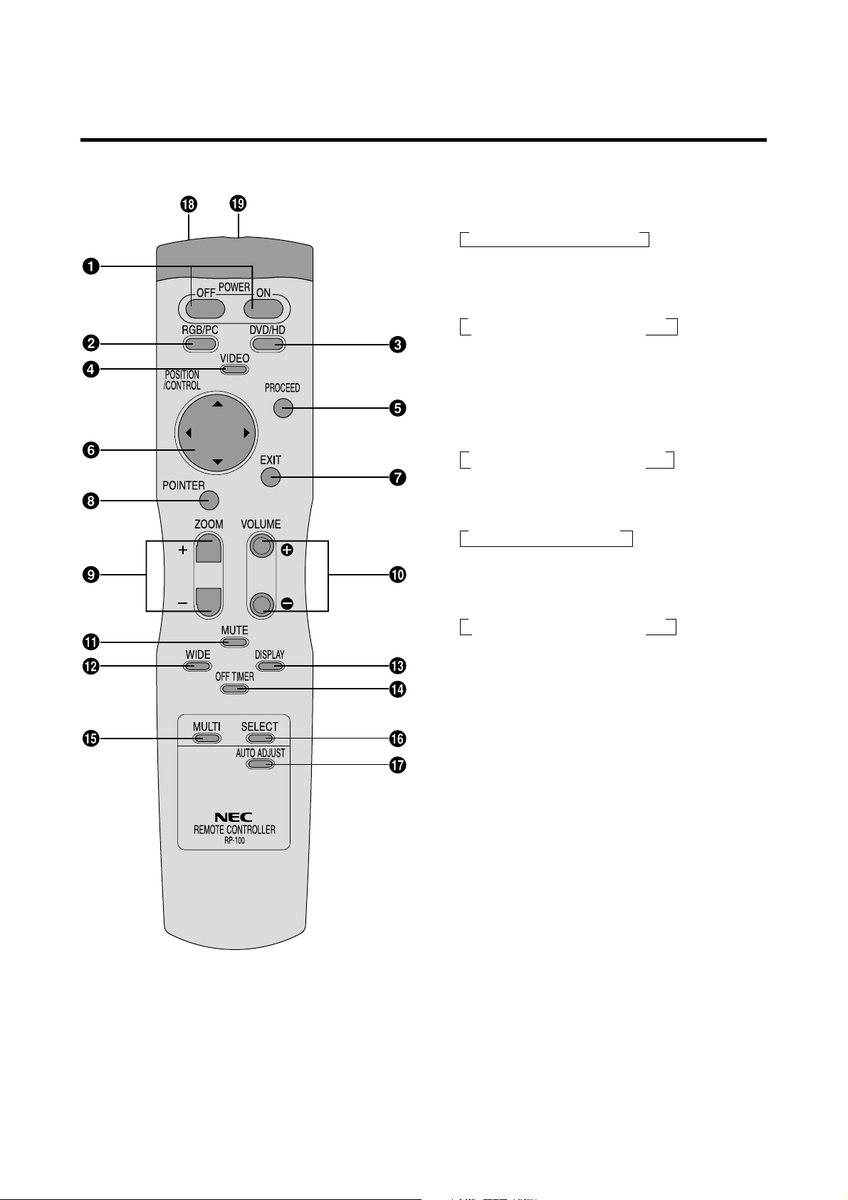
Remote Control Unit
w RGB/PC
Press this button to select RGB/PC as the source.
→ RGB/PC1 → RGB/PC2 → RGB/PC3
RGB/PC can also be selected using the INPUT
SELECT button on the monitor. The input switches as
follows each time the button is pressed:
→ VIDEO1 → VIDEO2→ VIDEO3→ DVD/HD
RGB/PC3 ← RGB/PC2 ← RGB/PC1 ←
e DVD / HD
Press this button to select DVD/HD as the source.
DVD/HD can also be selected using the INPUT
SELECT button on the monitor. The input switches as
follows each time the button is pressed:
→ VIDEO1 → VIDEO2→ VIDEO3→ DVD/HD
RGB/PC3 ← RGB/PC2 ← RGB/PC1 ←
r VIDEO
Press this button to select VIDEO as the source.
→ VIDEO1 → VIDEO2 → VIDEO3
VIDEO can also be selected using the INPUT SELECT
button on the monitor. The input switches as follows
each time the button is pressed:
→ VIDEO1 → VIDEO2→ VIDEO3→ DVD/HD
RGB/PC3 ← RGB/PC2 ← RGB/PC1 ←
q POWER ON/OFF
Switches Power ON/OFF.
(This does not operate when POWER/STANDBY
indicator of the main unit is off.)
t PROCEED
Press this button to access the OSM controls.
Press this button during the display of the main menu
to go to the sub menu.
y CURSOR (▲ / ▼ / / )
Use these buttons to select items or settings and to
adjust settings or switch the display patterns.
u EXIT
Press this button to exit the OSM controls in the main
menu. Press this button during the display of the sub
menu to return to the main menu.
i POINTER
Press this button to display the pointer.
o ZOOM (+ /–)
Enlarges or reduces the image.
!0 VOLUME (+ /–)
Adjusts the volume.
!1 MUTE
Mutes the sound.
!2 WIDE
The type of broadcast is detected automatically, and
the recommended wide screen is set.
E-5
Page 21
!3 DISPLAY
Displays the source settings on the screen.
!4 OFF TIMER
Activates the off timer for the unit.
!5 MULTI
Press this button to select a screen mode from among
single mode, side by side, and picture in picture.
!6 SELECT
Press this button to select the active picture in a multi
screen mode.
!7 AUTO ADJUST
Press this button to adjust Fine Picture, Picture ADJ,
Position, and Contrast automatically, or to switch the
screen size to ZOOM mode automatically with the
superimposed caption displayed fully only when the
picture contains dark areas above and below the picture.
!8 Remote control signal transmitter
Transmits the remote control signals.
!9 Remote Jack
Insert the plug of the supplied remote cable here when
using the supplied remote control unit in the wired
condition.
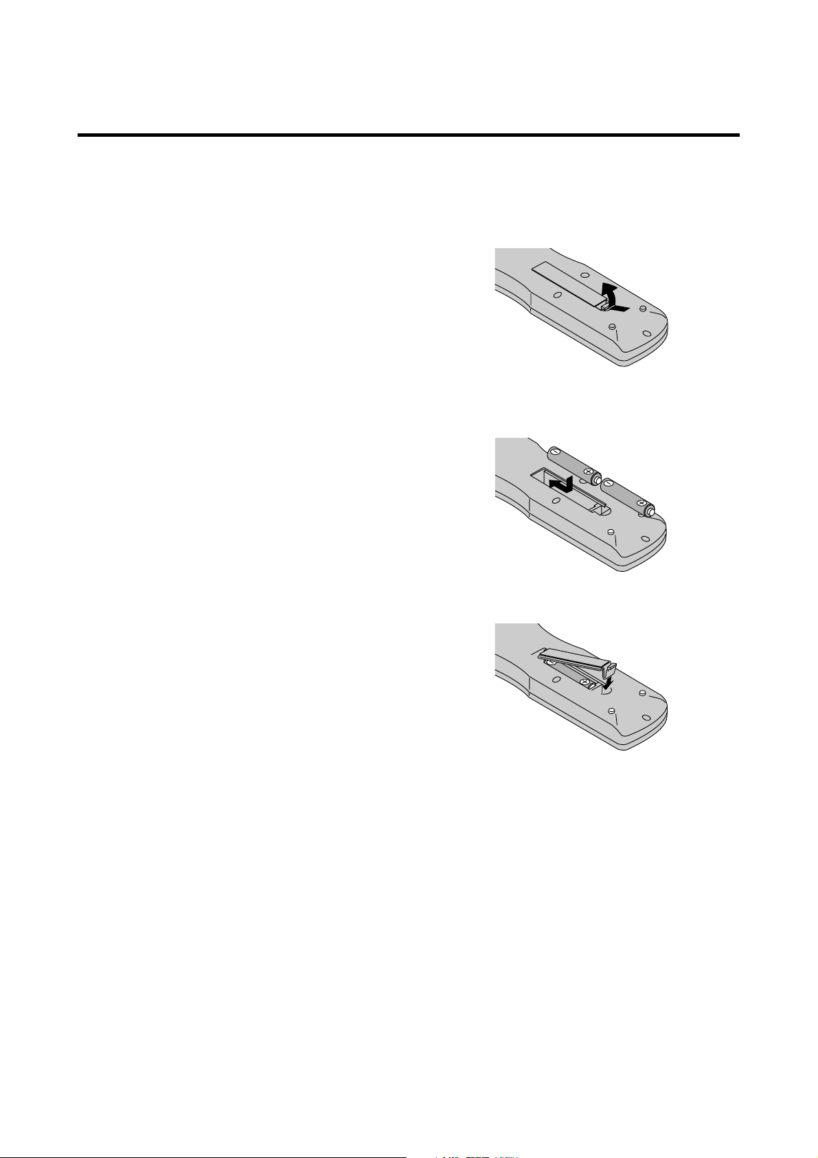
Battery Installation and Replacement
Insert the 2 “AAA” batteries, making sure to set them in
with the proper polarity.
1.Press and open the cover.
2.Align the batteries according to the (+) and (–) indication
inside the case.
3.Replace the cover.
E-6
Page 22
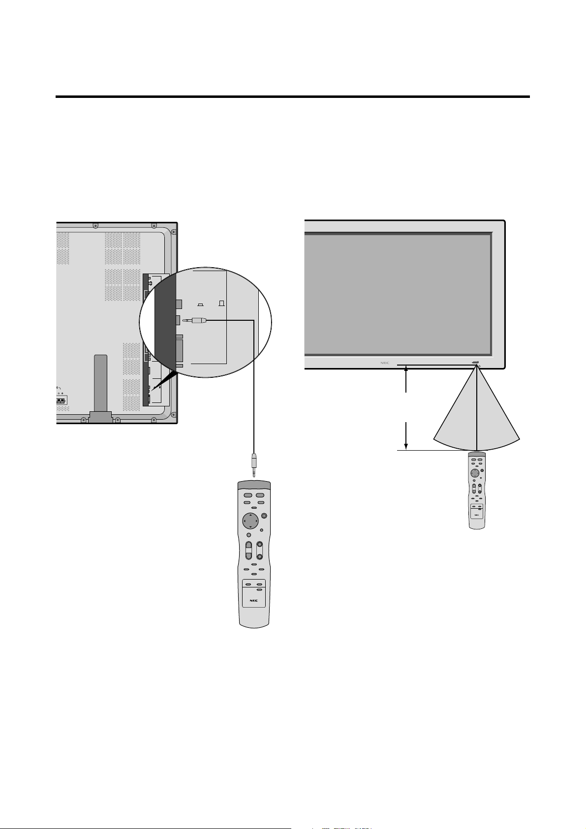
Using the wired remote control mode
O
R
N
REMOTE
CONTROL
EXTERNAL
CONTROL
CONTROL
LOCK
ON /OFF
L
Connect the supplied remote cable to the remote control
unit’s remote jack and the “REMOTE CONTROL”
terminal on the monitor.
When the cable is connected, the mode automatically
switches to wired remote control. When the wired remote
control mode is used, the remote control unit can be
operated even if no batteries are loaded.
VIDEO 1
VIDEO 2
VIDEO 3
L(MONO)
R
AUDIO 1RGB2/ DVD2/ HD2
Y
CB/PB
DVD1/HD1
CR/PR
L(MONO)
R
RGB 1
R/CR/PR
G/Y
B/CB/PB
HD
VD
L(MONO)
R
AUDIO 3 AUDIO 2
RGB 3
RS MUST
RE THAN
ATING
CE 6 OHM
LEFT
CONTROL
LOCK
ON /OFF
(Digital RGB)
REMOTE
CONTROL
EXTERNAL
CONTROL
Remote Control
Cable
Operating Range
* Use the remote control unit within a distance of about 7 m/
23ft. from the front of the monitor’s remote control sensor
and at a horizontal angle of within 30°.
* The remote control operation may not function if the
monitor’s remote control sensor is exposed to direct
sunlight or strong artificial light, or if there is an obstacle
between the sensor and the remote control unit.
UMEUPINPUT SELECT
/EXITLEFT/– RIGHT/+
POWER/STANDBY
Approx.
7m/ 23ft
30˚ 30˚
To Remote Jack
Handling the remote control unit
• Do not drop or mishandle the remote control unit.
• Do not get the remote control unit wet. If the remote
control unit gets wet, wipe it dry immediately.
• Avoid heat and humidity.
• When not using the remote control unit for a long period,
remove the batteries.
• Do not use new and old batteries together, or use different
types together.
• Do not take apart the batteries, heat them, or throw them
into a fire.
• When using the remote control unit in the wireless
condition, be sure to unplug the remote cable from the
REMOTE CONTROL terminal on the monitor.
E-7
Page 23
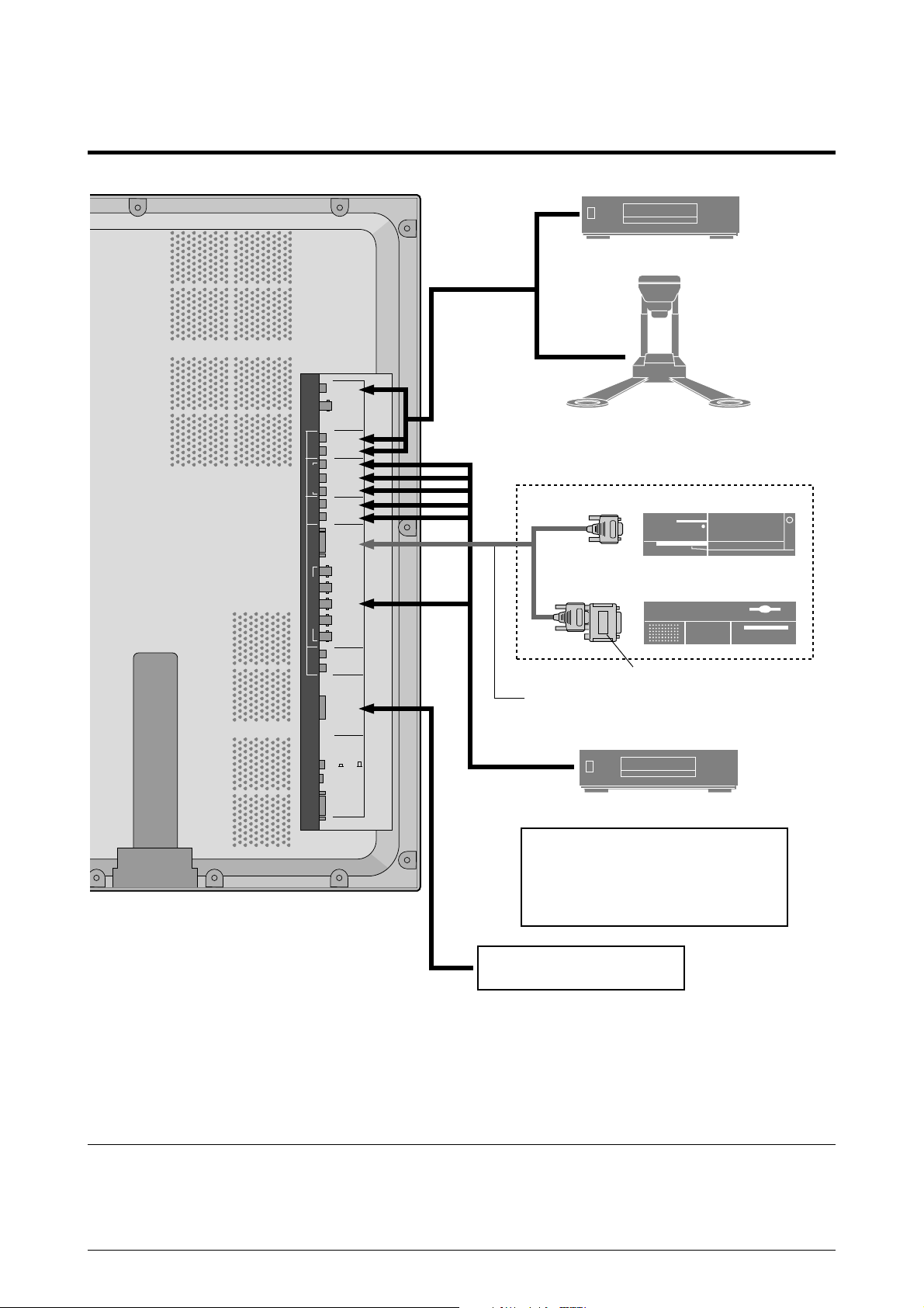
Installation
VCR or Laser Disc Player
VIDEO 1
VIDEO 2
VIDEO 3
L(MONO)
R
AUDIO 1RGB2/ DVD2/ HD2
Y
CB/PB
DVD1/HD1
CR/PR
L(MONO)
R
RGB 1
R/CR/PR
G/Y
B/CB/PB
HD
VD
L(MONO)
R
AUDIO 3 AUDIO 2
RGB 3
(Digital RGB)
CONTROL
LOCK
ON /OFF
REMOTE
CONTROL
EXTERNAL
CONTROL
To video inputs on
the plasma monitor
Document Camera
IBM VGA or
Compatibles
Macintosh or Compatibles
(Desk top type)
Monitor adapter for
Macintosh (supplied)
Signal cable (supplied)
To Mini D-Sub 15 pin connector on the plasma monitor
DVD Player
• For Y/CB/Cr, connect to the DVD1 or DVD2
terminals.
• For RGB + composite sync., connect to the
DVD2 terminals.
For composite sync., connect to the HD
terminals.
Personal computer with a
digital RGB output
Note:
This PlasmaSync monitor has the sapasity to display images when connected to European DVD players with a
SCART output signal, which is RGB with composite sync.
NEC can supply a special SCART cable, which will enable you to use the RGB with composite sync signal.
To obtain the special cable as well as for further information, please contact NEC help desk 0181 752 3535.
Please refer to page E-33 for selection of the correct mode in the on-screen manager.
E-8
Page 24

Connecting Your PC or Macintosh Computer
Connecting your PC or Macintosh computer to your plasma
monitor will enable you to display your computer’s screen
image for an impressive presentation. The plasma monitor
supports the signals described on page E-47.
To connect a PC, Macintosh or compatible graphics adapter,
simply:
1. Turn off the power to your plasma monitor and computer.
Connecting Your Document Camera
You can connect your plasma monitor to a document
camera. To do so, simply:
1. Turn off the power to your plasma monitor and
document camera.
2. Use a standard video cable to connect your document
camera to the Video input on your plasma monitor.
3. Turn on the plasma monitor and the document camera.
2. If your PC does not support XGA/SVGA/VGA you will
need to install an XGA/SVGA/VGA graphics board.
Consult your computer’s owner’s manual for your XGA/
SVGA/VGA configuration. If you need to install a new
board, see the manual that comes with your new graphics
board for installation instructions.
3. The plasma monitor provides signal compatibility up to
VESA 16001200 (UXGA). However, it is not
recommended to use this resolution due to image
readability on the monitors 1365768 native pixel
resolution panel.
4. Use the signal cable that’s supplied to connect your PC or
Macintosh computer to the plasma monitor. For Macintosh,
use the supplied monitor adapter to connect to your
computer’s video port.
5. Turn on the plasma monitor and the computer.
6. If the plasma monitor goes blank after a period of inactivity,
it may be caused by a screen saver installed on the computer
you’ve connected to the plasma monitor.
When using a Macintosh with the plasma monitor, the
following four display standards are supported using the
included Macintosh adapter :
13" fixed mode
16" fixed mode
19" fixed mode
21" fixed mode
The 19" fixed mode is recommended for the plasma monitor.
Note:
for more information about your camera’s video output
requirements.
Refer to your document camera owner’s manual
Connecting Your VCR or Laser Disc Player
Use common RCA cables (not provided) to connect your
VCR or laser disc player to your plasma monitor. To make
these connections, simply:
1. Turn off the power to your plasma monitor and VCR
or laser disc player.
2. Connect one end of your RCA cable to the video output
connector on the back of your VCR or laser disc player,
connect the other end to the Video input on your plasma
monitor. Use standard RCA audio patch cords to
connect the audio from your VCR or laser disc player
to your plasma monitor (if your VCR or laser disc player
has this capability). Be careful to keep your right and
left channel connections correct for stereo sound.
3. Turn on the plasma monitor and the VCR or laser disc
player.
Note:
manual for more information about your equipment’s video
output requirements.
Refer to your VCR or laser disc player owner’s
Connections with Equipment that has a Digital Interface
Connections can be made with equipment that is equipped
with a digital interface compliant with the DVI (Digital
Visual Interface) standard.
* Use a DVI 29-pin signal cable and the ferrite cores
(supplied) when making connections to the RGB3 IN (DVI)
connector of the main unit.
Note that the RGB3 IN(DVI) terminal does not support
analog RGB input source.
Note:
1. Input TMDS signals conforming to DVI standards.
The TMDS input corresponds to 1 link.
2. To maintain display quality, use a cable with a quality
prescribed by DVI standards that is within 5 meters in length.
Connecting Your DVD Player
You can connect your plasma monitor to a DVD player.
To do so, simply:
1. Turn off the power to your plasma monitor and DVD
player.
2. Use a standard video cable to connect your DVD player
to the Y, Cb, and Cr inputs on your plasma monitor.
Or use the DVD-player’s S-Video output. Use a
standard S-Video cable to connect to the S-Video input
on the plasma monitor.
3. Turn on the plasma monitor and the DVD player.
E-9
Page 25
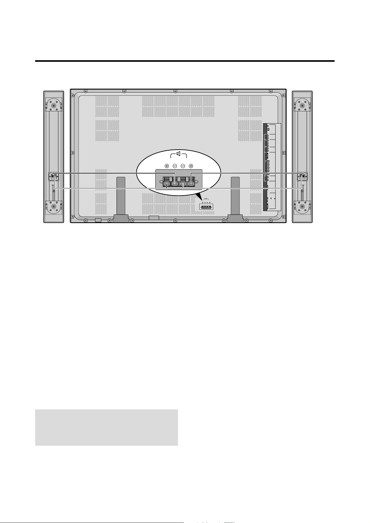
External Speaker Connections
AC IN
RIGHT LEFT
SPEAKERS MUST
HAVE MORE THAN
7WATT RATING
IMPEDANCE 5 OHM
RIGHT
LEFT
VIDEO 1
VIDEO 2
VIDEO 3
L(MONO)
R
AUDIO 1RGB2/ DVD2/ HD2
Y
CB/PB
DVD1/HD1
CR/PR
L(MONO)
R
RGB 1
R/CR/PR
G/Y
B/CB/PB
HD
VD
L(MONO)
R
AUDIO 3 AUDIO 2
RGB 3
(Digital RGB)
CONTROL
LOCK
ON /OFF
REMOTE
CONTROL
EXTERNAL
CONTROL
External speakers may be connected to the plasma monitor
to reproduce sound from VIDEO, DVD or RGB signal
sources.
External speakers may be connected directly to the
SPEAKERS terminals or indirectly by connecting a stereo
system amplifier to the audio outputs.
CAUTION:
Unplug the plasma monitor and all
connected components before connecting external
speakers. Use only speakers with 6-ohm impedance and
a power input rating of 7 watts or more.
To connect external speakers directly to the plasma
monitor:
1. Strip the ends of the speaker wires.
2. Press down the tabs below the SPEAKERS terminals,
insert the speaker wire and release the tab to secure the
speaker wire connection:
[a] Connect the right speaker (located at right side
of the monitor when viewed from the front)
positive (+) wire to RIGHT +.
[b] Connect the right speaker negative (–) wire to
RIGHT –.
[c] Connect the left speaker negative (–) wire to
LEFT–.
[d] Connect the left speaker positive (+) wire to
LEFT+.
E-10
Page 26
Pin Assignments and Signal Levels for 15 pin RGB (Analog)
5 4 3 2 1
10 9 8 7 6
15 14 13 12 11
Pin No.
1
2
3
4
5
6
7
8
9
10
11
12
13
14
15
Red
Green or sync-on-green
Blue
No connection
Ground
Red ground
Green ground
Blue ground
No connection
Sync signal ground
No connection
Bi-directional DATA (SDA)
Horizontal sync or Composite sync
Vertical sync
Data clock
Signal (Analog)
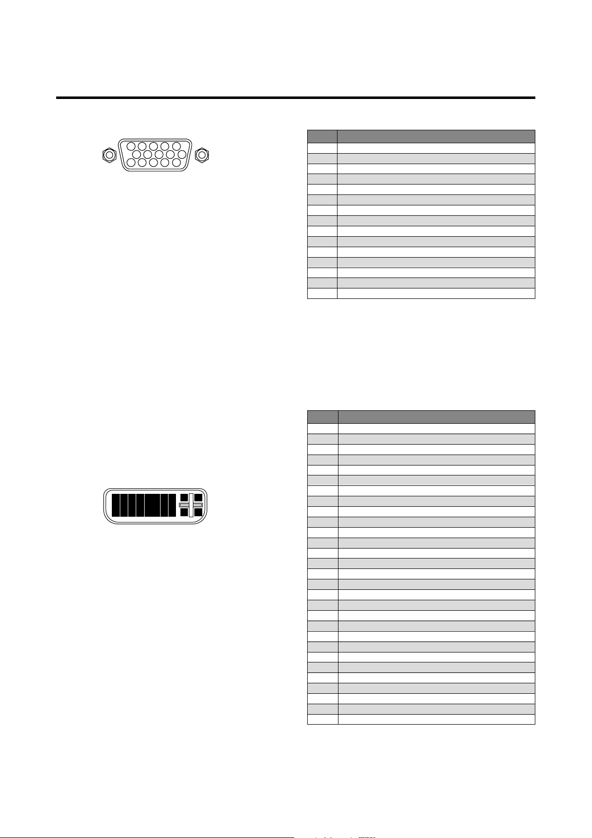
Pin Configuration and Signal of the RGB 3 IN Connector (DVI Connector)
The unit is equipped with a type of connector commonly
used for both analog and digital.
(Functionally, this cannot be used for an
analog input.)
(TMDS can be used for one link only.)
RGB 3
1
2
3
4
5
6
7
9
10
11
12
17
18
19
20
8 25 26
13
14
15
16
21
27 28
22
23
24
29
Pin No.
1
2
3
4
5
6
7
8
9
10
11
12
13
14
15
16
17
18
19
20
21
22
23
24
25
26
27
28
29
Signal (Digital)
T.M.D.S Data 2 T.M.D.S Data 2 +
T.M.D.S Data 2 Shield
No connection
No connection
DDC Clock
DDC Data
No connection
T.M.D.S Data 1 T.M.D.S Data 1 +
T.M.D.S Data 1 Shield
No connection
No connection
+5V Power
Ground
Hot Plug Detect
T.M.D.S Data 0 T.M.D.S Data 0 +
T.M.D.S Data 0 Shield
No connection
No connection
T.M.D.S Clock Shield
T.M.D.S Clock +
T.M.D.S Clock No connection
No connection
No connection
No connection
No connection
E-11
Page 27

Basic Operations
POWER
To turn the unit ON and OFF:
1. Plug the power cord into an active AC power outlet.
2. Press the POWER ON button (on the remote control
unit) to turn on the unit.
The monitor’s POWER/STANDBY indicator will light
up (green) when the unit is on.
3. Press the POWER OFF button (on the remote control
unit or the unit) to turn off the unit.
The monitor’s POWER/STANDBY indicator turns red
and the standby mode is set (only when turning off the
unit with the remote control unit).
VOLUME
To adjust the volume:
1. Press and hold the VOLUME button (on the remote
control unit or the unit) to increase to the desired level.
2. Press and hold the VOLUME
control unit or the unit) to decrease to the desired level.
button (on the remote
MUTE
To cancel the sound:
Press the MUTE button on the remote control unit to cancel
the sound; press again to restore.
DISPLAY
To check the settings:
1. The screen changes each time the DISPLAY button is
pressed.
2. If the button is not pressed for approximately three
seconds, the menu turns off.
DIGITAL ZOOM
Digital zoom specifies the picture position and enlarges
the picture.
1. Press the POINTER button to display the pointer. ( )
To change the size of the picture:
Press the ZOOM+ button and enlarge the picture.
The pointer will change to resemble a magnifying
glass. ( )
A press of the ZOOM- button will reduce the picture
and return it to its original size.
To change the picture position:
Select the position with the ▲▼ buttons.
2. Press the POINTER button to delete the pointer.
AUTO ADJUST
To adjust the size or quality of the picture automatically:
Press the AUTO ADJUST button.
Information
AUTO ADJUST ON setting
When RGB (still picture) input
is selected ...... Fine Picture, Picture ADJ, Position,
and Contrast will be adjusted
automatically.
When RGB (motion picture),
VIDEO, or Y/Pb/Pr (component) input
is selected ...... The screen size switches to ZOOM
mode automatically with the
superimposed caption displayed fully
only when the picture contains dark
areas above and below the picture.
E-12
Page 28

OFF TIMER
To set the off timer:
The off timer can be set to turn the power off after 30, 60,
90 or 120 minutes.
To cancel the off timer:
1. Press the OFF TIMER button twice in a row.
2. The off timer is canceled.
1. Press the OFF TIMER button to start the timer at 30
minutes.
2. Press the OFF TIMER button to the desired time.
3. The timer starts when the menu turns off.
→ 30 → 60 → 90 → 120 → 0
OFF TIMER30
To check the remaining time:
1. Once the off timer has been set, press the OFF TIMER
button once.
2. The remaining time is displayed, then turns off after a
few seconds.
OFF TIMER0
Note:
After the power is turned off with the off timer ...
A slight current is still supplied to the monitor. When you
are leaving the room or do not plan to use the system for a
long period of time, turn off the power of the monitor.
3. When five minutes remain the remaining time appears
until it reaches zero.
OFF TIMER28
E-13
Page 29
WIDE Operations
Watching with a wide screen
With this function, you can select one of four screen sizes.
When watching videos or digital video discs
1. Press the WIDE button on the remote control unit.
2. Within 3 seconds ...
Press the WIDE button again.
The screen size switches as follows:
→ ZOOM → NORMAL → FULL → STADIUM
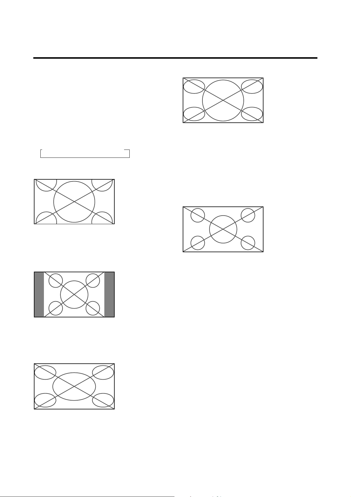
ZOOM size screen
The picture is expanded in the horizontal and vertical
direction, maintaining the original proportions.
* Use this for theater size (wide) movies, etc.
(manual)
STADIUM size screen
The picture is expanded in the horizontal and vertical
directions at different ratios.
* Use this for watching normal video programs (4:3) with a
wide screen.
When watching high definition video source
1. Press the WIDE button on the remote control unit.
FULL size screen (16 : 9)
NORMAL size screen (4:3)
The normal size screen is displayed.
* The picture has the same size as video pictures with a
4 : 3 aspect ratio.
FULL size screen
The image is expanded in the horizontal direction.
* Images compressed in the horizontal direction (“squeezed
images”) are expanded in the horizontal direction and
displayed on the entire screen. (Normal images are
expanded in the horizontal direction.)
The full size screen is displayed.
* The picture has the same size as video pictures (16 : 9).
E-14
Page 30
Watching computer images with a wide screen
Switch to the wide screen mode to expand the 4 : 3 image
to fill the entire screen.
1. Press the WIDE button on the remote control unit.
2. Within 3 seconds ...
Press the WIDE button again.
The screen size switches as follows:
→ NORMAL → FULL
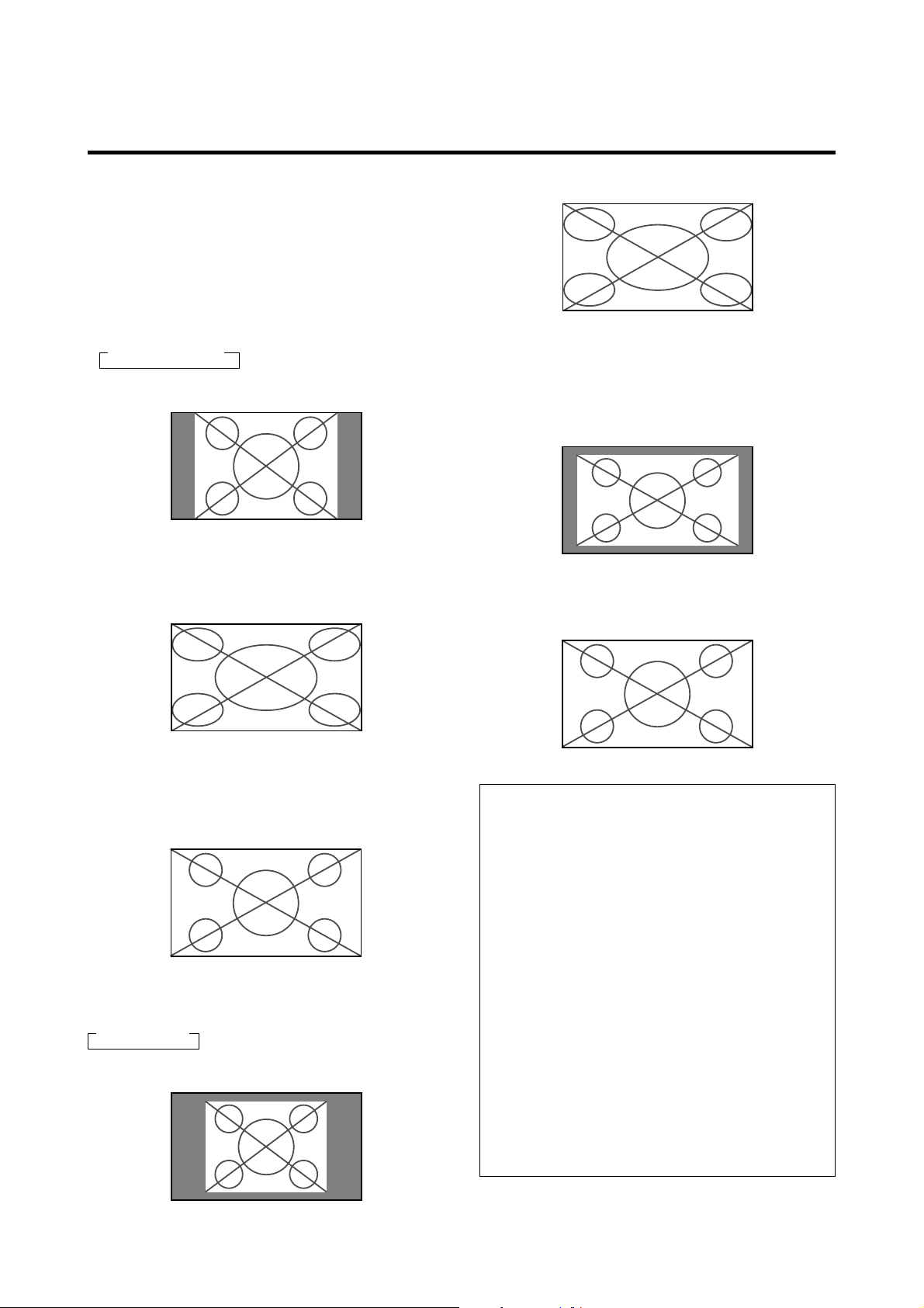
FULL size screen
The image is expanded in the horizontal and vertical
direction.
NORMAL size screen (4:3 or SXGA 5:4)
The picture has the same size as the normal computer
image.
FULL size screen
The image is expanded in the horizontal direction.
When wide signals are input.
FULL size screen
When wide signals are input.
TRUE
The image is true resolution.
FULL
Information
Supported resolution
See page E-47 for details on the display output of the
various VESA signal standards supported by the
monitor.
When “PICTURE SIZE” is set to “OFF”
The screen size switches as follows:
→ TRUE → FULL
TRUE size screen (VGA, SVGA 4:3)
The image is true resolution.
“PICTURE SIZE” setting
When the setting of “PICTURE SIZE” is OFF, the size
of RGB-input pictures will be TRUE in place of
NORMAL.
When 852 (848) dot 480 line wide VGA*
signals with a vertical frequency of 60 Hz and
horizontal frequency of 31.7 (31.0) kHz are input
Select an appropriate setting for RGB SELECT mode
referring to the“Table for Signals Supported” on page
E-47.
* “ IBM PC/AT” and “VGA” are registered trademarks
of IBM, Inc. of the United States.
E-15
Page 31

MULTI SCREEN Operations
VIDEO1 RGB/PC1
AB
VIDEO1 RGB/PC1
AB
Showing a couple of pictures on the screen at the same time
* An RGB-input picture may not be displayed in these modes,
depending on the input signal specifications.
1. Press the MULTI button to select a screen mode from
among single mode, side by side, and picture in picture.
Side by side 1
VIDEO1 RGB/PC1
AB
Selecting the input signals to be displayed
Press the cursor buttons on the remote control
unit to switch either side by side 1 (with ) or side by
side 2 (with ).
Note:
Picture A and B on the above screen are not always of the
same height.
Side by side 2
Picture in picture
Press the cursor buttons on the remote control
unit to switch the position of the sub screen.
Main screen
2. If you wish to switch the setting of the picture, press
the SELECT button to make the desired picture active.
Each press of the SELECT button changes the selection
of the active picture.
VIDEO1 RGB/PC1
Sub screen
screen
Main screen
VIDEO1
Sub
VIDEO1
Main screen
RGB/PC1
RGB/PC1
Sub
screen
1. Press the SELECT button to make the desired picture
active.
2. Press the RGB/PC, VIDEO, or DVD/HD button.
Each press of the button changes the selection of the
input signal.
The INPUT SELECT button on the monitor can also
be used to change the selection.
Adjusting the OSM controls
1. Press the PROCEED button to display the MAIN
MENU.
2. Adjust the setting to your preference.
For details, see “OSM (On Screen Menu) Controls” on
page E-17.
Note:
During multi mode, Auto Adjust does not affect the screen.
Information
Positioning on the screen (for side by side)
Depending on the input-signal selection,
positioning of the picture is settled as follows.
Pictures displayed
on the left ........ VIDEO1, VIDEO2, VIDEO3, HD1/
DVD1/DTV1, or HD2/DVD2/
DTV2
Pictures displayed
on the right ...... RGB/PC1, RGB/PC2, RGB/PC3
Positioning on the screen (for picture in
picture)
Pictures displayed
Main screen .... RGB/PC1, RGB/PC2, RGB/PC3,
HD 1/DVD 1/DTV 1, or HD 2/
DVD 2/DTV 2
Sub screen ...... VIDEO1, VIDEO 2, VIDEO 3, HD1/
DVD1/DTV1, or HD2/DVD2/DTV2
Multi screen operations may not function
depending on the type of the RGB signals.
E-16
Page 32

OSM(On Screen Menu) Controls
Menu Operations
The OSM window is displayed with respect to the
screen as shown on the diagram.
* Depending on the screen’s mode, the OSM may be
displayed slightly differently.
In the explanation, the OSM section is shown close up.
MAIN MENU
PICTURE
SOUND
SCREEN
FUNCTION
OPTIONS
INFORMATION
SEL. OK EXIT
EXITPROCEED
The following describes how to use the menus and the
selected items.
1. Press the PROCEED button on the remote control unit
to display the MAIN MENU.
MAIN MENU
PICTURE
SOUND
SCREEN
FUNCTION
OPTIONS
INFORMATION
5. The change is stored until you adjust it again.
6. Repeat steps 2 – 5 to adjust an additional item, or press
the EXIT button on the remote control unit to return to
the main menu.
Note:
The main menu disappears by pressing the EXIT
button.
SEL. OK EXIT
EXITPROCEED
2. Press the cursor buttons ▲ ▼ on the remote control
unit to highlight the menu you wish to enter.
3. Press the PROCEED button on the remote control unit
to select a submenu or item.
PICTURE
CONTRAST
BRIGHTNESS
SHARPNESS
COLOR
TINT
PICTURE MODE
COLOR TEMP.
NR
SEL. ADJ. RETURN
RG
MEMORY
:
2
:
OFF
:
EXIT
4. Adjust the level or change the setting of the selected
item by using the cursor buttons on the remote
control unit.
E-17
Page 33

Main menu Sub menu Functions Default Reset
PICTURE CONTRAST Adjusts the contrast. Center Yes
BRIGHTNESS Adjusts the brightness. Center Yes
SHARPNESS Adjusts the sharpness. Center Yes
COLOR Adjusts the color. Center Yes
TINT Adjusts the tint. Center Yes
PICTURE MODE Sets the picture mode according to the VIDEO environment and MEMORY Yes
image software.
COLOR TEMP Adjusts the color temperature and white balance. 2*
1
Yes
NR Reduces noise visible in image. OFF Yes
Main menu Sub menu Functions Default Reset
SOUND BASS Sets the bass. Center Yes
TREBLE Sets the treble. Center Yes
BALANCE Sets the left/right balance. Center Yes
Main menu Sub menu Functions Default Reset
SCREEN V-POSITION Adjusts the vertical position. Center Yes
H-POSITION Adjusts the horizontal position. Center Yes
V-HEIGHT Adjusts the vertical size. Min Yes
H-WIDTH Adjusts the horizontal size. Min Yes
1
AUTO PICTURE Turn this on to have the monitor automatically adjust “FINE PICTURE” OFF*
and “PICTURE ADJ”.
FINE PICTURE Adjusts for flickering on the computer image. Min*
PICTURE ADJ. Adjusts for striped patterns on the computer image. Center*
No
1
Yes
1
Yes
Main menu Sub menu Functions Default Reset
FUNCTION OSM
Turns the on-screen display (screen mode, etc.) off (when set to “OFF”).
ON Yes
When set to “ON”, the on-screen display is displayed.
OSM ADJ. Adjusts the vertical and horizontal positions of the menu display. 1 Yes
POWER MGT Sets the monitor for use as an energy-saving display when used with a OFF Yes
computer.
GRAY LEVEL In case of 4 : 3, sets the luminance of both sides. 3 Yes
CINEMA MODE Sets the picture to suit the movie. ON Yes
RGB3 ADJ. Adjusts the picture when the picture input from the RGB3 input 1 Yes
terminal is distorted.
LONG LIFE Sets the picture to reduce burn-in of the display. *
2
Yes
RESET Resets all the settings (PICTURE, SOUND, SCREEN, FUNCTION, — —
etc.) to the factory default values.
Main menu Sub menu Functions Default Reset
OPTION AUDIO INPUT Sets the allocation of the audio connectors. *
3
Yes
BNC SELECT Sets the BNC connectors. RGB Yes
RGB SELECT Sets the appropriate mode for the computer image. AUTO Yes
RGB (VGA signals), VIDEO (Moving picture), WIDE (WIDE VGA) DTV.
HD SELECT
Sets the digital broadcasting (1080A,1080B) or the High Vision (1035I).
1080B No
PICTURE SIZE Sets the picture size for RGB input. ON Yes
Main menu Sub menu Functions Default Reset
INFORMATION FREQUENCY Used to check the frequency and synchronizing polarities of the signal — —
currently being inputted.
LANGUAGE Sets the language of the menus (Japanese, English, German, French, English No
Swedish, Italian or Spanish).
COLOR SYSTEM Sets the VIDEO format (AUTO1, AUTO2, PAL, PAL-M, PAL-N, PAL60, AUTO1 No
SECAM, 4.43 NTSC or 3.58 NTSC).
E-18
*1 RGB/PC only.
*2 PLE: AUTO ORBITER: OFF INVERSE: OFF
*3 AUDIO1: VIDEO1 AUDIO2: HD/DVD1 AUDIO3: RGB1
Page 34

Picture Settings Menu
Adjusting the picture
The contrast, brightness, sharpness, color and tint can be
adjusted as desired.
4. Once the adjustment is completed ...
Press the EXIT button to return to the main menu.
To delete the main menu, press the EXIT button once
more.
Example: Adjusting the contrast
Press the PROCEED button on the remote control unit to
display the MAIN MENU on the screen, then...
1. Use the ▲ and ▼ buttons to select “PICTURE”, then
press the PROCEED button. The “PICTURE” screen
appears.
2. Use the ▲ and ▼ buttons to select “CONTRAST”.
PICTURE
CONTRAST
BRIGHTNESS
SHARPNESS
COLOR
TINT
PICTURE MODE
COLOR TEMP.
NR
SEL. ADJ. RETURN
RG
MEMORY
:
2
:
OFF
:
EXIT
3. Use the and buttons to adjust the contrast.
Note:
If “CAN NOT ADJUST” appears ...
When trying to enter the PICTURE submenu, make sure
PICTURE MODE is set to MEMORY.
Information
Picture adjustment screen
CONTRAST .... Changes the picture’s contrast.
BRIGHTNESS . Changes the picture’s brightness.
SHARPNESS ..Changes the picture’s sharpness.
Adjusts picture detail of VIDEO
display.
COLOR ........... Changes the color density.
TINT ................Changes the picture’s tint. Adjust for
natural colored skin, background, etc.
Adjusting the computer image
Only the contrast and brightness can be adjusted when
a computer signal is connected.
Restoring the factory default settings
Select “RESET” under the “PICTURE MODE” settings.
CONTRAST
* If neither the or button is pressed within 5 seconds,
the current setting is set and the previous screen
reappears.
E-19
Page 35

Setting the picture mode according to the brightness of the room
There are four picture modes that can be used effectively
according to the environment in which you are viewing
the display.
Example: Setting the “THEATER” mode
Press the PROCEED button on the remote control unit to
display the MAIN MENU on the screen, then...
1. Use the ▲ and ▼ buttons to select “PICTURE”, then
press the PROCEED button.
The “PICTURE” screen appears.
2. Use the ▲ and ▼ buttons to select “PICTURE MODE”.
PICTURE
CONTRAST
BRIGHTNESS
SHARPNESS
COLOR
TINT
PICTURE MODE
COLOR TEMP.
NR
RG
MEMORY
:
2
:
OFF
:
4. Once the adjustment is completed ...
Press the EXIT button to return to the main menu. To
delete the main menu, press the EXIT button once more.
Information
Types of picture modes
MEMORY ........ The last picture adjustments are stored
here.
THEATER ........ Set this mode when watching video in
a dark room.
This mode provides darker, finer
pictures, like the screen in movie
theaters.
CONTRAST = 80% for RESET mode
BRIGHTNESS = 95% for RESET
mode
NORMAL ......... Set this mode when watching video in
a bright room.
This mode provides dynamic pictures
with distinct differences between light
and dark sections.
CONTRAST = 96% for RESET mode
RESET ............ Use this to reset the picture to the
factory default settings.
SEL. ADJ. RETURN
EXIT
3. To set to “THEATER” ...
Use the and buttons to select “THEATER”.
The mode switches as follows when the and
buttons are pressed:
→ MEMORY ↔ THEATER ↔ NORMAL ↔ RESET ←
PICTURE MODE
THEATER:
* If neither the or button is pressed within 5 seconds,
the current selection is set and the previous screen
reappears.
E-20
Page 36

Setting the color temperature
Use this procedure to set color tone produced by the plasma
display.
Example: Setting “1”
4. Once the setting is completed...
Press the EXIT button to return to the main menu.
To delete the main menu, press the EXIT button once
more.
Press the PROCEED button on the remote control unit to
display the MAIN MENU on the screen, then...
1. Use the ▲ and ▼ buttons to select “PICTURE”, then
press the PROCEED button.
The “PICTURE” screen appears.
2. Use the ▲ and ▼ buttons to select “COLOR TEMP.”.
PICTURE
CONTRAST
BRIGHTNESS
SHARPNESS
COLOR
TINT
PICTURE MODE
COLOR TEMP.
NR
SEL. ADJ. RETURN
RG
MEMORY
:
2
:
OFF
:
EXIT
3. Use the and buttons to select “1”.
The mode switches as follows when the
and
buttons are pressed:
→ 1 ↔ 2 ↔ 3 ↔ PRO ←
Information
Setting the color temperature
1 ...................... High (bluer)
2 ......................... Middle (Standard)
3 ...................... Low (redder)
Restoring the factory default settings
Select “RESET” under the function menu. Note that this
also restores other settings to the factory defaults.
* See page E-22 to set “PRO”.
:
COLOR TEMP.
1
* If neither the or button is pressed within 5 seconds,
the current selection is set and the previous screen reappears.
E-21
Page 37

Adjusting the color to the desired quality
Use this procedure to adjust the white balance for bright
pictures and dark pictures to achieve the desired color
quality.
Example: Adjusting the “WHITE BALANCE”
Press the PROCEED button on the remote control unit to
display the MAIN MENU on the screen, then...
1. Use the ▲ and ▼ buttons to select “PICTURE”, then
press the PROCEED button.
The “PICTURE” screen appears.
2. Use the ▲ and ▼ buttons to select “COLOR TEMP.”.
PICTURE
CONTRAST
BRIGHTNESS
SHARPNESS
COLOR
TINT
PICTURE MODE
COLOR TEMP.
NR
SEL. ADJ. RETURN
RG
MEMORY
:
2
:
OFF
:
EXIT
4. Press the PROCEED button.
The “WHITE BALANCE” screen appears.
5. Use the ▲ and ▼ buttons to select “RED-GAIN”.
WHITE BALANCE
GAIN
RED
GREEN
BLUE
BIAS
RED
GREEN
BLUE
SEL. ADJ. RETURN
EXIT
6. Adjust the white balance using the and buttons.
R-GAIN
* If neither the or button is pressed within 5 seconds,
the current setting is set and the previous screen reappears.
3. Use the and buttons to select “PRO”.
The mode switches as follows when the
and
buttons are pressed:
→ 1 ↔ 2 ↔ 3 ↔ PRO ←
PRO:COLOR TEMP.
* If neither the or button is pressed within 5 seconds,
the current selection is set and the previous screen reappears.
7. Once the adjustment is completed...
Press the EXIT button to return to the main menu. To
delete the main menu, press the EXIT button once more.
Information
Adjusting the white balance
RGB-GAIN ....... White balance adjustment for signal
level
RGB-BIAS ....... White balance adjustment for black
level
Restoring the factory default settings
Select “RESET” under the function menu. Note that
this also restores other settings to the factory defaults.
E-22
Page 38

Reducing noise in the picture
Use these settings if the picture has noise due to poor
reception or when playing video tapes on which the picture
quality is poor.
4. Once the setting is completed ...
Press the EXIT button to return to the main menu.
To delete the main menu, press the EXIT button once
more.
Example: Setting “NR-3”
Press the PROCEED button on the remote control unit to
display the MAIN MENU on the screen, then...
1. Use the ▲ and ▼ buttons to select “PICTURE”, then
press the PROCEED button.
The “PICTURE” screen appears.
2. Use the ▲ and ▼ buttons to select “NR”.
PICTURE
CONTRAST
BRIGHTNESS
SHARPNESS
COLOR
TINT
PICTURE MODE
COLOR TEMP.
NR
SEL. ADJ. RETURN
RG
MEMORY
:
2
:
OFF
:
EXIT
3. Use the and buttons to select “NR-3”.
The mode switches as follows when the and
buttons are pressed:
→ OFF ↔ NR-1 ↔ NR-2 ↔ NR-3 ←
Information
NR
* “NR” stands for Noise Reduction.
* This function reduces noise in the picture.
Types of noise reduction
There are three types of noise reduction. Each has a
different level of noise reduction.
The effect becomes stronger as the number increases
(in the order NR-1 → NR-2 → NR-3).
OFF ............... Turns the noise reduction function off.
:
NR
NR-3
* If neither the or button is pressed within 5 seconds,
the current selection is set and the previous screen
reappears.
E-23
Page 39

Sound Settings Menu
Adjusting the treble, bass and left/right balance
The treble, bass and left/right balance can be adjusted to
suit your tastes.
Example: Adjusting the bass
To continue adjusting the sound ...
Repeat from step 2.
4. Once the adjustment is completed ...
Press the EXIT button to return to the main menu. To
delete the main menu, press the EXIT button once more.
Note:
If “CAN NOT ADJUST” appears...
Set “AUDIO INPUT” on the OPTION menu correctly.
Press the PROCEED button on the remote control unit to
display the MAIN MENU on the screen, then...
1. Use the ▲ and ▼ buttons to select “SOUND”, then
press the PROCEED button.
The “SOUND” screen appears.
2. To adjust the bass ...
Use the ▲ and ▼ buttons to select “BASS”.
SOUND
BASS
TREBLE
BALANCE
SEL. ADJ. RETURN
LR
EXIT
3. Adjust the bass using the and buttons.
SOUND
BASS
TREBLE
BALANCE
LR
Information
Sound settings menu
BASS .............. Changes the level of low frequency
sound.
TREBLE ..........Changes the level of high frequency
sound.
BALANCE ....... Changes the balance of the left and
right channels.
Restoring the factory default settings
Select “RESET” under the function menu. Note that
this also restores other settings to the factory defaults.
SEL. ADJ. RETURN
EXIT
* If neither the or button is pressed within 5 seconds,
the current selection is set and the previous screen reappears.
E-24
Page 40

Screen Settings Menu
Adjusting the Position, Size, Fine Picture, Picture Adj
The position of the image can be adjusted and flickering
of the image can be corrected.
Example: Adjusting the vertical position in the normal
mode
Press the PROCEED button on the remote control unit to
display the MAIN MENU on the screen, then...
3. Adjust using the 䊴 and 䊳 buttons.
V–POSITION
1. Use the ▲ and ▼ buttons to select “SCREEN”, then
press the PROCEED button. The “SCREEN” menu
appears.
Default settings (when RGB/PC is selected)
SCREEN
MODE
V–POSITION
H–POSITION
V–HEIGHT
H–WIDTH
AUTO PICTURE
FINE PICTURE
PICTURE ADJ.
SEL. ADJ. RETURN
NORMAL:
OFF:
EXIT
* The settings on the SCREEN menu are not preset at the
factory.
To select a mode ...
Use the
䊴
and 䊳 buttons to select a mode.
The mode switches as follows when the 䊴 and
buttons are pressed:
→ NORMAL ↔ FULL ←
* The mode can also be switched by pressing the “WIDE”
button on the remote control unit.
2. To adjust the vertical position ...
Use the ▲ and ▼ buttons to select “V-POSITION”.
SCREEN
MODE
V–POSITION
H–POSITION
V–HEIGHT
H–WIDTH
AUTO PICTURE
FINE PICTURE
PICTURE ADJ.
NORMAL:
OFF:
* If neither the 䊴 or 䊳 button is pressed within 5 seconds,
the current setting is set and the previous screen
reappears.
To continue making other computer image
adjustments ...
Repeat from step 2.
4. Once all adjustments are completed ...
Press the EXIT button to return to the main menu.
To delete the main menu, press the EXIT button once
more.
Information
䡵 When “AUTO PICTURE” is “OFF”
SCREEN
MODE
䊳
V–POSITION
H–POSITION
V–HEIGHT
H–WIDTH
AUTO PICTURE
FINE PICTURE
PICTURE ADJ.
SEL. ADJ. RETURN
When Auto Picture is off, the Fine Picture and the
Picture ADJ items are displayed so that you can adjust
them.
FULL:
OFF:
EXIT
SEL. ADJ. RETURN
EXIT
E-25
Page 41

Information
䡵 Adjusting the Auto Picture
ON ...................The Picture ADJ and Fine Picture
adjustments are made automatically.
OFF .................The Picture ADJ and Fine Picture
adjustments are made manually.
䡵 Adjusting the position of the image
V-POSITION ...Adjusts the vertical position of the
image.
H-POSITION ... Adjusts the horizontal position of the
image.
V-HEIGHT .......Adjusts the vertical size of the image.
(Except for STADIUM mode)
H-WIDTH ......... Adjusts the horizontal size of the
image. (Except for STADIUM mode)
FINE PICTURE
PICTURE ADJ* ....
* .. Adjusts for flickering.
Adjusts for striped patterns on the
image.
* The Picture ADJ and Fine Picture features are available
only when the “Auto Picture” is off.
* The AUTO PICTURE, FINE PICTURE and PICTURE
ADJ. are not available for VIDEO and HD/ DVD source.
Function Settings Menu
Setting the on-screen display
When using the monitor for presentations, etc., the monitor
can be set so that the input source, screen mode, etc., do
not appear.
Example: Turning the on-screen display mode off
Press the PROCEED button on the remote control unit to
display the MAIN MENU on the screen, then...
1. Use the ▲ and ▼ buttons to select “FUNCTION”, then
press the PROCEED button.
The “FUNCTION” screen appears.
2. Use the ▲ and ▼ buttons to select “OSM”.
FUNCTION
:
OSM
OSM ADJ.
POWER MGT
GRAY LEVEL
CINEMA MODE
RGB3 ADJ.
LONG LIFE
RESET
ON
:
1
:
OFF
:
3
:
ON
1:
䡵 Restoring the factory default settings
Select “RESET” under the function menu. Note that
this also restores other settings to the factory defaults
except for Auto Picture.
SEL. ADJ. RETURN
EXIT
3. To turn the on-screen display mode off ...
Use the 䊴 and 䊳 buttons to select “OFF”.
The mode switches as follows each time the 䊴 or
button is pressed:
ON ↔ OFF
FUNCTION
OSM
OSM ADJ.
POWER MGT
GRAY LEVEL
CINEMA MODE
RGB3 ADJ.
LONG LIFE
RESET
SEL. ADJ. RETURN
:
OFF
1
:
OFF
:
:
3
:
ON
1:
EXIT
4. Once the setting is completed ...
Press the EXIT button to return to the main menu.
To delete the main menu, press the EXIT button once
more.
Information
䊳
䡵 OSM modes
ON ................... The on-screen display appears.
OFF ................. The on-screen display does not appear.
䡵 Restoring the factory default settings
Select “RESET” under the function menu. Note that
this also restores other settings to the factory defaults.
E-26
Page 42

Adjusting the position of the menu display
OSM
OSM ADJ.
POWER MGT
GRAY LEVEL
CINEMA MODE
ON
1
OFF
3
ON
:
:
:
:
:
SEL. ADJ. RETURN
EXIT
FUNCTION
FUNCTION
OSM
OSM ADJ.
POWER MGT
GRAY LEVEL
CINEMA MODE
ON
2
OFF
3
ON
:
:
:
:
:
SEL. ADJ. RETURN
EXIT
1:
LONG LIFE
RGB3 ADJ.
RESET
LONG LIFE
RESET
1:
RGB3 ADJ.
Use these operations to adjust the position of the menus
that appear on the screen.
Example: Adjusting the position of the menu display
Press the PROCEED button on the remote control unit to
display the MAIN MENU on the screen, then...
1. Use the ▲ and ▼ buttons to select “FUNCTION”,
then press the PROCEED button.
The “FUNCTION” menu appears.
2. Use the ▲ and ▼ buttons to select “OSM ADJ.”
FUNCTION
:
OSM
OSM ADJ.
POWER MGT
GRAY LEVEL
CINEMA MODE
RGB3 ADJ.
LONG LIFE
RESET
ON
:
1
:
OFF
:
3
:
ON
1:
3. To adjust the position...
Adjust using the 䊴 and 䊳 buttons.
SEL. ADJ. RETURN
FUNCTION
OSM
OSM ADJ.
POWER MGT
GRAY LEVEL
CINEMA MODE
RGB3 ADJ.
LONG LIFE
RESET
SEL. ADJ. RETURN
EXIT
ON
:
1
:
OFF
:
3
:
ON
:
1
:
EXIT
4. Once all adjustments are completed ...
Press the EXIT button to return to the main menu.
To delete the main menu, press the EXIT button once
more.
Information
䡵 Adjusting the position of the menu display
The position can be set
123
between 1 and 9.
456
789
䡵 Restoring the factory default settings
Select “RESET” under the function menu. Note that
this also restores other settings to the factory defaults.
E-27
Page 43

Setting the power management for computer images
This energy-saving (power management) function
automatically reduces the monitor’s power consumption
if no operation is performed for a certain amount of time.
Example: Turning the power management function on
Press the PROCEED button on the remote control unit to
display the MAIN MENU on the screen, then...
1. Use the ▲ and ▼ buttons to select “FUNCTION”, then
press the PROCEED button.
The “FUNCTION” screen appears.
2. Use the ▲ and ▼ buttons to select “POWER MGT”.
FUNCTION
:
OSM
OSM ADJ.
POWER MGT
GRAY LEVEL
CINEMA MODE
RGB3 ADJ.
LONG LIFE
RESET
ON
:
1
OFF
:
3
:
ON
:
1:
Information
䡵 Power management function
* The power management function automatically reduces
the monitor’s power consumption if the computer’s
keyboard or mouse is not operated for a certain amount
of time. This function can be used when using the
monitor with a computer conforming to the VESA
DPMS format.
* If the computer’s power is not turned on or if the
computer and selector tuner are not properly connected,
the system is set to the off state.
* For instructions on using the computer’s power
management function, refer to the computer’s operating
instructions.
䡵 Power management settings
ON ................... In this mode the power management
function is turned on.
OFF ................. In this mode the power management
function is turned off.
SEL. ADJ. RETURN
EXIT
3. To turn the power management function on ...
Use the 䊴 and 䊳 buttons to select “ON”.
The mode switches as follows each time the 䊴 or
button is pressed:
ON ↔ OFF
FUNCTION
:
OSM
OSM ADJ.
POWER MGT
GRAY LEVEL
CINEMA MODE
RGB3 ADJ.
LONG LIFE
RESET
SEL. ADJ. RETURN
ON
:
1
:
ON
:
3
:
ON
1:
EXIT
4. Once the setting is completed ...
Press the EXIT button to return to the main menu.
To delete the main menu, press the EXIT button once
more.
䡵 Power management function and POWER/
STANDBY indicator
The POWER/STANDBY indicator indicates the status
䊳
of the power management function. See page E-29 for
indicator status and description.
䡵 Restoring the factory default settings
Select “RESET” under the function menu. Note that
this also restores other settings to the factory defaults.
E-28
Page 44

POWER/STANDBY indicator
Power management
mode
On
Standby
Suspend
Off
POWER/STANDBY
indicator
Green
Orange
Red
Red
Power management
operating status
Not activated.
Activated.
Activated.
Activated.
Horizontal and vertical synchronizing
signals are present from the computer.
No horizontal synchronizing signals
are sent from the computer.
No vertical synchronizing signals are
sent from the computer.
No horizontal or vertical synchronizing
signals are sent from the computer.
Description
Turning the picture back on
Picture already on.
Operate the keyboard or mouse. The
picture reappears immediately.
Operate the keyboard or mouse. The
picture reappears, but more time is
required than from the standby
mode.
Operate the keyboard or mouse. The
picture reappears, but more time is
required than from the standby mode
or suspend mode.
E-29
Page 45

Setting the gray level for the sides of the screen
Use this procedure to set the gray level for the parts on the
screen on which nothing is displayed when the screen is
set to the 4:3 size.
Setting the picture to suit the movie
The film image is automatically discriminated and
projected in an image mode suited to the picture.
[NTSC, PAL60, 480I(60Hz) only]
Example: Adjusting the “GRAY LEVEL”
Press the PROCEED button on the remote control unit to
display the MAIN MENU on the screen, then...
1. Use the ▲ and ▼ buttons to select “FUNCTION”, then
press the PROCEED button.
The “FUNCTION” screen appears.
2. Use the ▲ and ▼ buttons to select “GRAY LEVEL”.
FUNCTION
OSM
OSM ADJ.
POWER MGT
GRAY LEVEL
CINEMA MODE
RGB3 ADJ.
LONG LIFE
RESET
SEL. ADJ. RETURN
:
ON
:
1
:
OFF
:
3
ON
:
1:
EXIT
3. To adjust the “GRAY LEVEL”...
Use the 䊴 and 䊳 buttons to adjust the GRAY LEVEL.
FUNCTION
:
OSM
OSM ADJ.
POWER MGT
GRAY LEVEL
CINEMA MODE
RGB3 ADJ.
LONG LIFE
RESET
SEL. ADJ. RETURN
ON
:
1
:
OFF
:
9
:
ON
1:
EXIT
5. Once the setting is completed ...
Press the EXIT button to return to the main menu.
To delete the main menu, press the EXIT button once
more.
Information
䡵 GRAY LEVEL
This adjusts the brightness of the black (the gray level)
for the sides of the screen.
The standard is 0 (black). The level can be adjusted
from 0 to 15. The factory setting is 3 (dark gray).
Example: Setting the “CINEMA MODE” to “OFF”
Press the PROCEED button on the remote control unit to
display the MAIN MENU on the screen, then...
1. Use the ▲ and ▼ buttons to select “FUNCTION”, then
press the PROCEED button.
The “FUNCTION” screen appears.
2. Use the ▲ and ▼ buttons to select “CINEMA MODE”.
FUNCTION
OSM
OSM ADJ.
POWER MGT
GRAY LEVEL
CINEMA MODE
RGB3 ADJ.
LONG LIFE
RESET
SEL. ADJ. RETURN
:
ON
:
1
:
OFF
:
3
:
ON
1:
EXIT
3. To set the CINEMA MODE to “OFF” ...
Use the 䊴 and 䊳 buttons to select “OFF”.
The mode switches as follows each time the 䊴 or
button is pressed:
→ ON ↔ OFF ←
FUNCTION
:
OSM
OSM ADJ.
POWER MGT
GRAY LEVEL
CINEMA MODE
RGB3 ADJ.
LONG LIFE
RESET
SEL. ADJ. RETURN
ON
:
1
:
OFF
:
3
:
OFF
1:
EXIT
4. Once the setting is completed ...
Press the EXIT button to return to the main menu.
To delete the main menu, press the EXIT button once
more.
Information
䡵 CINEMA MODE
ON ................... Automatic discrimination of the
image and projection in cinema mode.
OFF ................... Cinema mode does not function.
䊳
䡵 Restoring the factory default settings
Select “RESET” under the function menu. Note that
this also restores other settings to the factory defaults.
䡵 Restoring the factory default settings
Select “RESET” under the function menu. Note that
this also restores other settings to the factory defaults.
E-30
Page 46

Setting RGB3 ADJ.
When the picture input from the RGB3 input terminal is
distorted, select the most appropriate setting from among
“1”, “2”, and “3”.
Reducing burn-in of the screen
The brightness of the screen, the position of the picture,
and positive/negative mode are adjusted to reduce burnin of the screen.
Example: Setting “2”
Press the PROCEED button on the remote control unit to
display MAIN MENU on the screen, then...
1. Use the ▲ and ▼ buttons to select “FUNCTION”,
then press the PROCEED button.
The “FUNCTION” screen appears.
2. Use the ▲ and ▼ buttons to select “RGB3 ADJ.”.
FUNCTION
OSM
OSM ADJ.
POWER MGT
GRAY LEVEL
CINEMA MODE
RGB3 ADJ.
LONG LIFE
RESET
SEL. ADJ. RETURN
:
ON
:
1
:
OFF
:
3
ON
:
1:
EXIT
3. To select “2”...
Use the 䊴 and 䊳 buttons to select “2”.
The mode switches as follows each time the 䊴 or 䊳
buton is pressed:
→ 1 ↔ 2 ↔ 3 ←
FUNCTION
OSM
OSM ADJ.
POWER MGT
GRAY LEVEL
CINEMA MODE
RGB3 ADJ.
LONG LIFE
RESET
SEL. ADJ. RETURN
:
ON
:
1
:
OFF
:
3
ON
:
2:
EXIT
Example: Setting “PLE” to “LOCK”
Press the PROCEED button on the remote control unit to
display the MAIN MENU on the screen, then proceed as
follows.
1. Use the ▲ and ▼ buttons to select “FUNCTION”, then
press the PROCEED button.
The “FUNCTION” screen appears.
2. Use the ▲ and ▼ buttons to select “LONG LIFE”, then
press the PROCEED button.
FUNCTION
OSM
OSM ADJ.
POWER MGT
GRAY LEVEL
CINEMA MODE
LONG LIFE
RESET
PROCEED
SEL. RETURN
OK
ON
:
1
:
OFF
:
3
:
:
ON
1:RGB3 ADJ.
EXIT
The “LONG LIFE” screen appears.
3. Use the ▲ and ▼ buttons to select “PLE”, then use the
䊴
and 䊳 buttons to select “LOCK”.
The mode switch changes as follows each time the
or 䊳 button is pressed:
AUTO ↔ LOCK
LONG LIFE
PLE
ORBITER
INVERSE
:
:
:
LOCK
OFF
OFF
䊴
4. Once the setting is completed...
Press the EXIT button to return to the main menu.
To delete the main menu, press the EXIT button once
more.
Information
䡵 When you adjust the RGB3 ADJ.
The position of the menu display will change. In such
a case, be sure to adjust the position.
䡵 Restoring the factory default settings
Select “RESET” under the function menu. Note that
this also restores other settings to the factory defaults.
SEL. ADJ. RETURN
4. Once the setting is completed...
Press the EXIT button to return to the FUNCTION
menu.
To exit the main menu, press the EXIT button twice.
E-31
EXIT
Page 47

Information
䡵 PLE
AUTO .............. The brightness of the screen is
adjusted automatically to suit the
picture quality.
LOCK .............. The brightness level is set to
minimum.
䡵 ORBITER
ON ...................The picture moves around the screen
intermittently.
OFF .................Orbiter mode does not function.
䡵 INVERSE
ON ..................... The picture is displayed alternately
between positive image and negative
image.
OFF .................Inverse mode does not function.
WT ..................The entire screen turns white.
䡵 Restoring the factory default settings
Select “RESET” from the function menu. Note that this
also restores other settings to the factory defaults.
Resetting to the default values
Use these operations to restore all the picture adjustments,
audio settings, to the factory default values.
Refer to page E-18 for items to be reset.
Press the PROCEED button on the remote control unit to
display the MAIN MENU on the screen, then...
1. Use the ▲ and ▼ buttons to select “FUNCTION”, then
press the PROCEED button.
The “FUNCTION” screen appears.
2. Use the ▲ and ▼ buttons to select “RESET”, then press
the PROCEED button.
FUNCTION
OSM
OSM ADJ.
POWER MGT
GRAY LEVEL
CINEMA MODE
LONG LIFE
RESET
SEL. RETURN
PROCEED
OK
ON
:
1
:
OFF
:
3
:
:
ON
1:RGB3 ADJ.
EXIT
The “RESET” screen appears.
3. Use the ▲ and ▼ buttons to select “RESET”, then press
the PROCEED button.
RESET
RESET
RETURN
OK RETURN
EXITPROCEED
RESET
SETTING NOW
When the “SETTING NOW” screen disappears, the
screen will be restored to the previous “RESET” mode,
then all the settings are restored to the default values.
4. Once the setting is completed ...
Press the EXIT button.
To delete the main menu, press the EXIT button once
more.
E-32
Page 48

Option Settings Menu
Setting the allocation of the audio connectors
Setting the AUDIO 1, 2, and 3 connectors to the desired
input.
Setting the BNC connectors
Select whether to set the input of the 5 BNC connectors to
RGB or component.
Example: Set the BNC SELECT mode to “COMP.”
Example: Setting “AUDIO 1” to “VIDEO 2”
Press the PROCEED button on the remote control unit to
display the MAIN MENU on the screen, then...
1. Use the ▲ and ▼ buttons to select “OPTION”, then
press the PROCEED button.
The “OPTION” screen appears.
2. Use the ▲ and ▼ buttons to select “AUDIO 1”.
OPTION
AUDIO INPUT
AUDIO1
AUDIO2
AUDIO3
BNC SELECT
RGB SELECT
HD SELECT
PICTURE SIZE
SEL. ADJ. RETURN
VIDEO1
:
:
HD/DVD1
RGB1
:
RGB
:
:
AUTO
:
1080B
:
ON
EXIT
3. To set the AUDIO1 to “VIDEO2”...
Use the 䊴 and 䊳 buttons to select “VIDEO2”.
The mode switches as follows each time the 䊴 or
䊳
button is pressed:
→
VIDEO1 ↔ VIDEO2 ↔ VIDEO3 ↔ HD/DVD1 ↔ RGB/PC1 ↔ RGB/PC2 ↔ RGB/PC3
OPTION
AUDIO INPUT
AUDIO1
AUDIO2
AUDIO3
BNC SELECT
RGB SELECT
HD SELECT
PICTURE SIZE
VIDEO2
:
HD/DVD1
:
RGB1
:
RGB
:
AUTO
:
1080B
:
ON
:
←
Press the PROCEED button on the remote control unit to
display the MAIN MENU on the screen, then...
1. Use the ▲ and ▼ buttons to select “OPTION”, then
press the PROCEED button.
The “OPTION” screen appears.
2. Use the ▲ and ▼ buttons to select “BNC SELECT”.
OPTION
AUDIO INPUT
AUDIO1
AUDIO2
AUDIO3
BNC SELECT
RGB SELECT
HD SELECT
PICTURE SIZE
SEL. ADJ. RETURN
:
VIDEO1
HD/DVD1
:
RGB1
:
:
RGB
:
AUTO
:
1080B
:
ON
EXIT
3. To set the BNC SELECT mode to “COMP.”...
Use the 䊴 and 䊳 buttons to select “COMP.”.
The mode switches as follows each time the 䊴 or
button is pressed:
→
RGB ↔ COMP. ↔ SCART
AUDIO INPUT
AUDIO1
AUDIO2
AUDIO3
BNC SELECT
RGB SELECT
HD SELECT
PICTURE SIZE
SEL. ADJ. RETURN
←
OPTION
:
:
:
:
:
:
:
VIDEO1
HD/DVD1
RGB1
COMP.
AUTO
1080B
ON
EXIT
䊳
SEL. ADJ. RETURN
EXIT
4. Once the setting is completed...
Press the EXIT button to return to the main menu.
To delete the main menu, press the EXIT button once
more.
Information
䡵 AUDIO INPUT
A single audio input cannot be selected as the audio
channel for more than one input terminal.
䡵 Restoring the factory default settings
Select “RESET” under the function menu. Note that
this also restores other settings to the factory defaults.
4. Once the setting is completed...
Press the EXIT button to return to the main menu.
To delete the main menu, press the EXIT button once
more.
E-33
Page 49

Information
䡵 BNC SELECT
RGB ................ Uses the 5BNC terminal for RGB
input.
COMP. ............. Use the 3BNC terminal for component
input.
SCART ............ Use the 4BNC terminal for RGB with
composite sync input. See page E-8.
䡵 Restoring the factory default settings
Select “RESET” under the function menu. Note that
this also restores other settings to the factory defaults.
Setting a computer image to the correct RGB select screen
With the computer image, select the RGB Select mode
for a moving image such as (video) mode, wide mode or
digital broadcast.
Example: Setting the “RGB SELECT” mode to
“MOTION ”
Press the PROCEED button on the remote control unit to
display the MAIN MENU on the screen, then...
1. Use the ▲ and ▼ buttons to select “OPTION”, then
press the PROCEED button.
The “OPTION” screen appears.
2. Use the ▲ and ▼ buttons to select “RGB SELECT”.
OPTION
AUDIO INPUT
AUDIO1
AUDIO2
AUDIO3
BNC SELECT
RGB SELECT
HD SELECT
PICTURE SIZE
:
VIDEO1
:
HD/DVD1
:
RGB1
RGB
:
AUTO
:
:
1080B
:
ON
SEL. ADJ. RETURN
EXIT
3. To set the RGB select mode to “MOTION” ...
Use the 䊴 and 䊳 buttons to select “MOTION”.
The mode switches as follows each time the 䊴 or
button is pressed:
→ AUTO ↔ STILL ↔ MOTION ↔ WIDE1 ↔ WIDE2 ↔ DTV ←
OPTION
AUDIO INPUT
AUDIO1
AUDIO2
AUDIO3
BNC SELECT
RGB SELECT
HD SELECT
PICTURE SIZE
SEL. ADJ. RETURN
:
VIDEO1
HD/DVD1
:
RGB1
:
RGB
:
:
MOTION
1080B
:
:
ON
EXIT
4. Once the setting is completed ...
Press the EXIT button to return to the main menu.
To delete the main menu, press the EXIT button once
more.
䊳
E-34
Page 50

Information
䡵 RGB SELECT modes
One of these 6 modes must be selected in order to
display the following signals correctly.
AUTO .............. Select the suitable mode for the
specifications of input signals as
listed in the table “Computer input
signals supported by this system” on
page E-47.
STILL ..............To display VESA standard signals.
(Use this mode for a still image from
a computer.)
MOTION.......... The video signal (from a scan
converter) will be converted to RGB
signals to make the picture more
easily viewable. (Use this mode for a
motion image from a computer.)
WIDE1............. When an 852 dot⳯ 480 line signal
with a horizontal frequency of
31.7kHz is input, the image may be
compressed horizontally. To prevent
this, set RGB SELECT to WIDE1.
WIDE2............. When an 848 dot⳯ 480 line signal
with a horizontal frequency of 31.0
kHz is input, the image may be
compressed horizontally. To prevent
this, set RGB SELECT to WIDE2.
DTV .................Set this mode when watching digital
broadcasting (480P).
See page E-47 for the details of the above settings.
Setting high definition images to the suitable screen size
Use this procedure to set whether the number of vertical
lines of the input high definition image is 1035 or 1080.
Example: Setting the “1080B” mode to “1035I”
Press the PROCEED button on the remote control unit to
display the MAIN MENU on the screen, then...
1. Use the ▲ and ▼ buttons to select “OPTION”, then
press the PROCEED button.
The “OPTION” screen appears.
2. Use the ▲ and ▼ buttons to select “HD SELECT”.
OPTION
AUDIO INPUT
AUDIO1
AUDIO2
AUDIO3
BNC SELECT
RGB SELECT
HD SELECT
PICTURE SIZE
SEL. ADJ. RETURN
:
VIDEO1
:
HD/DVD1
:
RGB1
RGB
:
AUTO
:
1080B
:
ON
:
EXIT
3. To set the HD SELECT mode to “1035I” ...
Use the 䊴 and 䊳 buttons to select “1035I”.
The mode switches as follows each time the 䊴 or
button is pressed:
→1080A ↔ 1080B ↔ 1035I ←
䊳
䡵 Restoring the factory default settings
Select “RESET” under the function menu. Note that
this also restores other settings to the factory defaults.
OPTION
AUDIO INPUT
AUDIO1
AUDIO2
AUDIO3
BNC SELECT
RGB SELECT
HD SELECT
PICTURE SIZE
SEL. ADJ. RETURN
:
VIDEO1
:
HD/DVD1
:
RGB1
RGB
:
AUTO
:
1035I
:
ON
:
EXIT
4. Once the setting is completed ...
Press the EXIT button to return to the main menu.
To delete the main menu, press the EXIT button once
more.
Information
䡵 HD SELECT modes
These 3 modes are not displayed in correct image
automatically.
1080A ............... Special Digital broadcasts (for
example : DTC100)
1080B ............... Standard digital broadcasts
1035I ...............Japanese “High Vision” signal format
E-35
Page 51

Setting the picture size for RGB input signals
Use this procedure to switch the setting to “ON” or “OFF”.
Example: Setting the “ON” mode to “OFF”
Press the PROCEED button on the remote control unit to
display the MAIN MENU on the screen, then...
1. Use the ▲ and ▼ buttons to select “OPTION”, then
press the PROCEED button.
The “OPTION” screen appears.
2. Use the ▲ and ▼ buttons to select “PICTURE SIZE”.
OPTION
AUDIO INPUT
AUDIO1
AUDIO2
AUDIO3
BNC SELECT
RGB SELECT
HD SELECT
PICTURE SIZE
:
VIDEO1
:
HD/DVD1
:
RGB1
:
RGB
:
AUTO
1080B
:
:
ON
Information Menu
Checking the frequencies, polarities of input
signals, and resolution
Use this function to check the frequencies and polarities
of the signals currently being input from a computer, etc.
Press the PROCEED button on the remote control unit to
display the MAIN MENU on the screen, then...
1. Use the ▲ and ▼ buttons to select “INFORMATION”,
then press the PROCEED button.
The “INFORMATION” screen appears.
2. Use the ▲ and ▼ buttons to select “FREQUENCY”,
then press the PROCEED button.
INFORMATION
FREQUENCY
LANGUAGE
COLOR SYSTEM
SEL. ADJ. RETURN
EXIT
3. To set PICTURE SIZE mode to “OFF”...
Use the 䊴 and 䊳 buttons to select “OFF”.
The mode switches as follows when the 䊴 or 䊳 buttons
are pressed:
ON ↔ OFF
OPTION
AUDIO INPUT
AUDIO1
AUDIO2
AUDIO3
BNC SELECT
RGB SELECT
HD SELECT
PICTURE SIZE
SEL. ADJ. RETURN
:
VIDEO1
:
HD/DVD1
:
RGB1
:
RGB
:
AUTO
:
1080B
:
OFF
EXIT
4. Once the setting is completed ...
Press the EXIT button to return to the main menu.
To delete the main menu, press the EXIT button once
more.
Information
䡵 PICTURE SIZE
ON ..................... For RGB Input: “NORMAL” and
“FULL” can be selected for Wide-
Screen switching.
OFF ................... For RGB Input: “TRUE” and
“FULL” can be selected for WideScreen switching.
RETURN
EXIT
OK
PROCEED
SEL.
3. The frequency is displayed.
FREQUENCY
H. FREQ
V. FREQ
H. POL
V. POL
MODE
RESOLUTION
:
37.5KHz
:
75.0Hz
:
NEG.
:
NEG.
:
8
:
640⳯480
EXIT
RETURN
* Press the EXIT button to return to the previous screen.
4. Once you have checked the frequency ...
Press the EXIT button to return to the main menu.
To delete the main menu, press the EXIT button once
more.
䡵 Restoring the factory default settings
Select “RESET” under the function menu. Note that
this also restores other settings to the factory defaults.
E-36
Page 52

Setting the language for the menus
The menu display can be set to one of seven languages:
Japanese, English, German, French, Swedish, Italian or
Spanish.
Example: Setting the menu display to “DEUTSCH”
Setting the video signal format
Use these operations to set the video signal format.
Example: Setting the video signal format to “3.58
NTSC”
Press the PROCEED button on the remote control unit to
display the MAIN MENU on the screen, then...
1. Use the ▲ and ▼ buttons to select “INFORMATION”,
then press the PROCEED button. The
“INFORMATION” screen appears.
2. Use the ▲ and ▼ buttons to select “LANGUAGE”,
then press the PROCEED button.
INFORMATION
FREQUENCY
LANGUAGE
COLOR SYSTEM
EXIT
SEL.
PROCEED
OK
RETURN
The “LANGUAGE” screen appears.
3. To select “ DEUTSCH ” ...
䊴
Use the
The mode switches as follows when the 䊴 and
and 䊳 buttons to select “ DEUTSCH ”.
䊳
buttons are pressed:
→ ENGLISH ↔ DEUTSCH ↔ FRANÇAIS ←
→ ↔ SVENSKA ↔ ITALIANO ↔ ESPAÑOL ←
LANGUAGE
LANGUAGE
DEUTSCH:
Press the PROCEED button on the remote control unit to
display the MAIN MENU on the screen, then...
1. Use the ▲ and ▼ buttons to select “INFORMATION”,
then press the PROCEED button.
The “INFORMATION” screen appears.
2. Use the ▲ and ▼ buttons to select “COLOR SYSTEM”,
then press the PROCEED button.
INFORMATION
FREQUENCY
LANGUAGE
COLOR SYSTEM
RETURN
EXIT
OK
PROCEED
SEL.
The “COLOR SYSTEM” screen appears.
COLOR SYSTEM
COLOR SYSTEM
AUTO1:
EXIT
ADJ.
PROCEED
OK
RETURN
4. Press the PROCEED button.
The display language is switched to Deutsch.
5. Once the setting is completed ...
Press the EXIT button to return to the main menu.
To delete the main menu, press the EXIT button once
more.
Information
䡵 Language settings
ENGLISH ........ English
DEUTSCH....... German
FRANÇAIS ...... French
ESPAÑOL ....... Spanish
ITALIANO ........ Italian
SVENSKA .......Swedish
.............. Japanese
3. To select “3.58 NTSC” ...
Use the 䊴 and 䊳 buttons to select “3.58 NTSC”.
The mode switches as follows when the 䊴 and
buttons are pressed:
→ AUTO1 ↔ AUTO2 ↔ 3.58NTSC ↔ 4.43NTSC ←
→ SECAM ↔ PAL-M ↔ PAL-N ↔ PAL60 ↔ PAL ←
COLOR SYSTEM
E-37
ADJ. RETURN
COLOR SYSTEM
3.58NTSC:
ADJ. RETURN
EXIT
EXIT
䊳
Page 53

4. Once the setting is completed ...
Press the EXIT button to return to the main menu.
To delete the main menu, press the EXIT button once
more.
The color system is set to “3.58 NTSC”.
Information
䡵 Video signal formats
Different countries use different formats for video
signals. Set to the format used in your current country.
AUTO1/2 ......... The video signals are automatically
detected and the format is set
accordingly.
AUTO1: 3.58NTSC, 4.43NTSC, PAL, SECAM,
PAL60
AUTO2: PAL-M, PAL-N, 3.58NTSC
PAL (B, G) ....... This is the standard format used
mainly in the United Kingdom and
Germany.
SECAM............. This is the standard format used
mainly in France and Russia.
4.43 NTSC,
PAL60 .............. This format is used for videos in
countries using PAL and SECAM
video signals.
3.58 NTSC ...... This is the standard format used
mainly in Japan and the United States.
PAL-M ............. This is the standard format used
mainly in Brazil.
PAL-N ..............This is the standard format used
mainly in Argentina.
E-38
Page 54

External Control
Application
These specifications cover the communications control of
the plasma monitor by external equipment.
Connections
Connections are made as described below.
plasma monitor
1) Connector on the plasma monitor side: EXTERNAL
CONTROL connector.
Type of connector: D-Sub 9-pin male
No. Pin Name
1 No Connection
2 RXD (Receive data)
3 TXD (Transmit data)
4 DTR (DTE side ready)
5 GND
6 DSR (DCE side ready)
7 RTS (Ready to send)
8 CTS (Clear to send)
9 No Connection
External equipment
e.g., Personal computer
Communication Parameters
(1) Communication system Asynchronous
(2) Interface RS-232C
(3) Baud rate 9600 bps
(4) Data length 8 bits
(5) Parity Odd
(6) Stop bit 1 bit
(7) Communication code Hex
1
5
9
6
2) Connector on the external equipment side: Serial port
(RS-232C) connector.
See the specifications of the equipment that is to be
connected for the type of connector and the pin
assignment.
3) Wiring
Use a crossed (reverse) cable.
Wire the cable so that each pair of data lines cross
between the two devices. These data line pairs are RXD
(Receive data) and TXD (Transmit data), DTR (DTE
side ready) and DSR (DCE side ready), and RTS (Ready
to send) and CTS (Clear to send).
E-39
Page 55

Communication Format
DFH 80H 60H 47H 01H 01H 08H
Command 1 Unit ID 1 Unit ID 2 Command 2 Data Length Data Check Sum
Total 208H
▲
8 bit 8 bit 8 bit 8 bit 8 bit 8 bit 8 bit
8 bit
Command 1
Unit ID 1
Unit ID 2
Command 2
Data length
Data
Check sum
Command 1
Command 1, along with command 2, is a number used to
distinguish each command.
In the case of ACK, when the lower order 4 bits is FH (as
in 3FH and 7FH), this indicates that the commands and
data of the supported equipment have been received. When
the lower order 4 bits is BH (as in 3BH and 7BH), this
indicates that unsupported commands and data have been
received.
Check Sum Example
2) Error Processing
• When the communication interval is vacant for more
than 4 ms, thereafter a received Command 1 will be
recognized. If, at this time, meaningful data cannot
be recognized, that data will not be recognized (as
valid data).
• An ACK will not be returned unless the receive data
error, the check sum error, and the receive data are all
taken in.
Unit ID 1 and Unit ID 2
Unit ID 1 and unit ID 2 are numbers used to identify the
equipment that is to be connected.
60H is used for the plasma monitor and 80H is used for
external control equipment such as a personal computer.
1) Unit ID 1: Indicates the equipment sending the signal
2) Unit ID 2: Indicates the equipment receiving the signal
Command 2
Command 2, along with command 1, is a number used to
distinguish each command.
Check Sum (CKS), Error Processing, and ACK
1) The check sum described below and RS-232C odd
parity are used together for a check of the received data.
The check sum is the lower order 8 bits of one frame of
sent or received data comprising the sum total of
Command 1, Unit ID 1 and 2, Command 2, Data Length,
and Data.
E-40
Page 56

Command Reference List
CMD1 CMD2 LEN
01. Power ON 9FH 4EH 00H
02. Power OFF 9FH 4FH 00H
03. Input Switch Change DFH 47H 01H
04. VOLUME Gain Data DFH 7FH 03H
05. SCREEN MODE Select DFH 51H 01H
06. AUDIO Mute On 9FH 3EH 00H
07. AUDIO Mute Off 9FH 3FH 00H
08. OSM Select DFH 58H 01H
09. Color Gain Data DFH 7FH 03H
10. TINT Gain Data DFH 7FH 03H
11. SHARPNESS Gain Data DFH 7FH 03H
12. CONTRAST Gain Data DFH 7FH 03H
13. BRIGHT Gain Data DFH 7FH 03H
14. Input MODE Request 1FH 41H 00H
15. RESET 1FH 54H 00H
16. COLOR TEMP SELECT DFH 00H 01H
17. RED Gain Data DFH 7FH 04H
18. GREEN Gain Data DFH 7FH 04H
19. BLUE Gain Data DFH 7FH 04H
20. VIDEO ADJ Request 1FH 45H 00H
21. Audio Select Set DFH 70H 02H
22. Audio Select Request 1FH 6FH 00H
23. LONG LIFE Set DFH 6BH 03H
24. Failure Mode Request 1FH 3FH 00H
03. Input Switch Change
Function
The external control equipment switches the input of the plasma monitor.
Transmission Data
DFH 80H 60H 47H 01H DATA00 CKS
DATA00 : Input Select 01H: Video1
02H: Video2
03H: Video3
05H: HD (HD1 or DTV or DTV1)
06H: HD2 (DTV2)
07H: RGB1/PC1
08H: RGB2/PC2
0CH: RGB3/PC3
ACK
The plasma monitor returns the following ACK when the input is switched.
3FH 60H 80H 47H 00H CKS
04. VOLUME Gain Data
Function
The external control equipment changes the VOLUME gain data of the plasma
monitor.
Transmission Data
DFH 80H 60H 7FH 03H
DATA00 USER SOUND Gain Flag 05H
DATA01 VOLUME Gain Flag 01H
DATA02 VOLUME Gain 00H: Step 0
DATA00 DATA01 DATA02 CKS
01. Power ON
Function
The external control equipment switches on the power of the plasma monitor.
Transmission Data
9FH 80H 60H 4EH 00H CKS
ACK
The plasma monitor returns the following ACK when the power is switched on.
3FH 60H 80H 4EH 00H CKS
NOTE: Do not set the Power ON or Power OFF command
continuously.
02. Power OFF
Function
The external control equipment switches off the power of the plasma monitor.
Transmission Data
9FH 80H 60H 4FH 00H CKS
ACK
The plasma monitor returns the following ACK when the power is switched off.
3FH 60H 80H 4FH 00H CKS
NOTE: Do not set the Power ON or Power OFF command
continuously.
0AH: Step 10 (Default)
2AH: Step 42
ACK
7FH 60H 80H 7FH 02H
DATA00 USER SOUND Gain Flag 05H
DATA01 VOLUME Gain Flag 01H
DATA00 DATA01
CKS
05. SCREEN MODE Select
Function
The external control equipment switches the screen mode of the plasma monitor.
Transmission Data
DFH 80H 60H 51H 01H DATA00 CKS
DATA00 02H : STADIUM
03H : ZOOM
04H : NORMAL
05H : FULL
06H : TRUE (REAL)
ACK
7FH 60H 80H 51H 01H DATA00 CKS
DATA00 02H : STADIUM
03H : ZOOM
04H : NORMAL
05H : FULL
E-41
06H : TRUE (REAL)
Page 57

06. AUDIO Mute On
Function
The external control equipment switches on AUDIO Mute of the plasma monitor.
Transmission Data
9FH 80H 60H 3EH 00H CKS
ACK
3FH 60H 80H 3EH 00H CKS
07. AUDIO Mute Off
Function
The external control equipment switches off AUDIO Mute of the plasma monitor.
Transmission Data
9FH 80H 60H 3FH 00H CKS
ACK
3FH 60H 80H 3FH 00H CKS
08. OSM Select
Function
The external control equipment switches on or off the on-screen display (OSM)
of the plasma monitor.
Transmission Data
DFH 80H 60H 58H 01H DATA00 CKS
DATA00 01H : Screen display On
02H : Screen display Off
ACK
7FH 60H 80H 58H 01H DATA00 CKS
DATA00 01H : Screen display On
02H : Screen display Off
Screen display On/Off is equivalent to the screen display On/Off
function of the convenient function settings.
*Operation is as described in the table below.
09. COLOR Gain Data
Function
The external control equipment changes the COLOR gain data of the plasma
monitor.
Transmission Data
DFH 80H 60H 7FH 03H
DATA00: USER PICTURE Gain Flag 01H
DATA01: COLOR Gain Flag 04H
DATA02: COLOR Gain E0H: -32
* COLOR Gain is from -22 (EAH) to
+22 (16H) only during video. FFH: -01
DATA00 DATA01 DATA02
00H: 0
01H: +01
20H: +32
CKS
ACK
7FH 60H 80H 7FH 02H
DATA00: USER PICTURE Gain Flag 01H
DATA01: COLOR Gain Flag 04H
DATA00 DATA01
CKS
10.TINT Gain Data
Function
The external control equipment changes the TINT gain data of the plasma
monitor.
Transmission Data
DFH 80H 60H 7FH 03H
DATA00: USER PICTURE Gain Flag 01H
DATA01: TINT Gain Flag 05H
DATA02: TINT Gain E0H: -32
* TINT Gain is from -22 (EAH) to
+22 (16H) only during video. FFH: -01
ACK
7FH 60H 80H 7FH 02H
DATA00: USER PICTURE Gain Flag 01H
DATA01: TINT Gain Flag 05H
DATA00 DATA01 DATA02
00H: 0
01H: +01
20H: +32
DATA00 DATA01 CKS
CKS
Operation
Remote control operation
Personal computer control operation
On-Screen Display (OSD)
Display of items and adjustments on the menu
When screen display is ON
Ye s Ye s Ye s N o
No No Yes No
When screen display is OFF When screen display is ON When screen display is OFF
Volume display, input display, and screen size display
E-42
Page 58

11. SHARPNESS Gain Data
Function
The external control equipment changes the SHARPNESS gain data of the
plasma monitor.
Transmission Data
DFH 80H 60H 7FH 03H
DATA00: USER PICTURE Gain Flag 01H
DATA01: SHARPNESS Gain Flag 06H
DATA02: SHARPNESS Gain F0H: -16
ACK
7FH 60H 80H 7FH 02H
DATA00: USER PICTURE Gain Flag 01H
DATA01: SHARPNESS Gain Flag 06H
DATA00 DATA01 DATA02
FFH: -01
00H: 0
01H: +01
10H:+16
DATA00 DATA01
CKS
CKS
ACK
7FH 60H 80H 7FH 02H
DATA00: USER PICTURE Gain Flag 01H
DATA01: BRIGHT Gain Flag 08H
DATA00 DATA01
CKS
14. Input MODE Request
Function
The display returns the current input information by the external control
equipment’ s request.
Transmission Data
1FH 80H 60H 41H 00H CKS
ACK
7FH 60H 80H 41H 01H DATA00 CKS
DATA00: Input Select
01H: Video1 02H: Video2
03H: Video3 04H: HD (HD1 or DTV or DTV1)
05H: RGB1/PC1 06H: RGB2/PC2
0AH:DVD (DVD1) 0CH:HD2 (DTV2)
0DH:DVD2 0EH:RGB3/PC3
12. CONTRAST Gain Data
Function
The external control equipment changes the CONTRAST gain data of the plasma
monitor.
Transmission Data
DFH 80H 60H 7FH 03H
DATA00: USER PICTURE Gain Flag 01H
DATA01: CONTRAST Gain Flag 07H
DATA02: CONTRAST Gain CCH : -52
DATA00 DATA01 DATA02
FFH: -01
00H: 0
01H: +01
14H: +20
CKS
ACK
7FH 60H 80H 7FH 02H
DATA00: USER PICTURE Gain Flag 01H
DATA01: CONTRAST Gain Flag 07H
DATA00 DATA01
CKS
13. BRIGHT Gain Data
Function
The external control equipment changes the BRIGHT gain data of the plasma
monitor.
Transmission Data
DFH 80H 60H 7FH 03H
DATA00: USER PICTURE Gain Flag 01H
DATA01: BRIGHT Gain Flag 08H
DATA02: BRIGHT Gain E0H: -32
DATA00 DATA01 DATA02
CKS
15. RESET
Function
The external control equipment resets the user adjustment of the plasma
monitor.
Transmission Data
1FH 80H 60H 54H 00H CKS
ACK
3FH 60H 80H 54H 00H CKS
16. COLOR TEMP SELECT
Function
The external control equipment changes the COLOR TEMP of the plasma
monitor.
Transmission Data
DFH 80H 60H 00H 01H DATA00 CKS
DATA00
00H: 1
01H: 2
02H: 3
03H: PRO
ACK
7FH 60H 80H 00H 01H DATA00 CKS
DATA00:
00H: 1
01H: 2
02H: 3
03H: PRO
FFH: -01
00H: 0
01H: +01
20H: +32
NOTE: Set so that at the selection of 1, 2, or 3 of COLOR TEMP
change of the following R/G/B GAIN data cannot be accepted.
(This must be operated in the same way as OSD menu.)
E-43
Page 59

17. RED Gain Data
Function
The external control equipment changes the RED Gain Data of the plasma
monitor.
Transmission Data
DFH 80H 60H 7FH 04H DATA00 to DATA03 CKS
DATA00: USER PICTURE Gain Flag 01H
DATA01: RED Gain Flag 01H
DATA02: RED Gain 1 (Bias) D8H: -40
19. BLUE Gain Data
Function
The external control equipment changes the BLUE Gain Data of the plasma
monitor.
Transmission Data
DFH 80H 60H 7FH 04H DATA00 to DATA03 CKS
DATA00: USER PICTURE Gain Flag 01H
DATA01: BLUE Gain Flag 03H
DATA02: BLUE Gain1(Bias) D8H:-40
FFH: -1
00H: 0
IEH: +30
DATA03: RED Gain 2 (Drive) D8H: -40
FFH: -1
00H: 0
IEH: +30
ACK
7FH 60H 80H 7FH 02H
DATA00: USER PICTURE Gain Flag 01H
DATA01: RED Gain Flag 01H
DATA00 DATA01
CKS
18. GREEN Gain Data
Function
The external control equipment changes the GREEN Gain Data of the plasma
monitor.
Transmission Data
DFH 80H 60H 7FH 04H DATA00 to DATA03 CKS
DATA00: USER PICTURE Gain Flag 01H
DATA01: GREEN Gain Flag 02H
DATA02: GREEN Gain 1 (Bias) D8H: -40
FFH:-1
00H: 0
IEH: +30
DATA03: BLUE Gain2(Drive) D8H: -40
FFH:-1
00H: 0
IEH:+30
ACK
7FH 60H 80H 7FH 02H
DATA00: USER PICTURE Gain Flag 01H
DATA01: BLUE Gain Flag 03H
DATA00 DATA01
CKS
FFH: -1
00H: 0
IEH: +30
DATA03: GREEN Gain2 (Drive) D8H: -40
FFH: -1
00H: 0
IEH: +30
ACK
7FH 60H 80H 7FH 02H
DATA00: USER PICTURE Gain Flag 01H
DATA01: GREEN Gain Flag 02H
DATA00 DATA01
CKS
E-44
Page 60

20. VIDEO ADJ Request
Function
The display returns the video adjustments information by the external control
equipment’s request.
Transmission Data
1FH 80H 60H 45H 00H CKS
ACK
7FH 60H 80H 45H 0CH DATA00 to DATA0B CKS
DATA00: RED Gain(Bias) D8H: -40
FFH: -1
00H: 0
DATA05: SHARPNESS Gain F0H: -16
FFH: -01
00H: 0
01H: +01
10H: +16
DATA06: CONTRAST Gain CCH: -52
FFH: -01
00H: 0
01H: +01
IEH: +30
DATA01: GREEN Gain(Bias) D8H: -40
FFH: -1
00H: 0
IEH: +30
DATA02: BLUE Gain(Bias) D8H: -40
FFH: -1
00H: 0
IEH: +30
DATA03: COLOR Gain E0H: -32
* COLOR Gain is from -22 (EAH) to FFH: -01
+22 (16H) only during video. 00H: 0
01H: +01
20H: +32
DATA04: TINT Gain E0H: -32
14H: +20
DATA07: BRIGHT Gain E0H: -32
FFH: -01
00H: 0
01H: +01
20H: +32
DATA08: RED Gain(Drive) D8H: -40
FFH: -1
00H: 0
IEH: +30
DATA09: GREEN Gain(Drive) D8H: -40
FFH: -1
00H: 0
IEH: +30
DATA0A: BLUE Gain(Drive) D8H: -40
* TINT Gain is from -22 (EAH) to FFH: -01
+22 (16H) only during video. 00H: 0
01H: +01
20H: +32
FFH: -1
00H: 0
IEH: +30
DATA0B: COLOR TEMP 00H: 1
01H: 2
02H: 3
03H: PRO
E-45
Page 61

21. Audio Select Set
Function
The external control equipment sets combinations of audio and video inputs
for the plasma monitor.
Transmission Data
DFH 80H 60H 70H 02H
DATA00: AUDIO INPUT
01H: AUDIO 1
02H: AUDIO 2
03H: AUDIO 3
DATA01: VISUAL INPUT
01H: Video 1
02H: Video 2
03H: Video 3
05H: HD (HD1 or DTV or DTV1)
06H: HD2 (DTV2)
07H: RGB 1/ PC 1
08H: RGB 2/ PC 2
0CH: RGB 3/ PC 3
DATA00 DATA01
CKS
ACK
The plasma monitor returns the following ACK when the input is switched.
3FH 60H 80H 70H 00H CKS
* The plasma monitor returns “Not Available” when selecting the
video input same as the one set at one of the AUDIO 01 to 3.
Example:
The plasma monitor returns “Not Available” when selecting the
VIDEO1 for AUDIO2 or VIDEO3 after VIDEO1 has been set to
AUDIO1.
22. Audio Select Request
Function
The external control equipment inquires the current combinations of audio
and video inputs for the plasma monitor.
Transmission Data
1FH 80H 60H 6FH 00H CKS
ACK
The plasma monitor returns the following ACK:
7FH 60H 80H 6FH 03H
DATA00: AUDIO 1
DATA01: AUDIO 2
DATA02: AUDIO 3
VISUAL INPUT DATA
01H: Video 1
02H: Video 2
03H: Video 3
05H: HD (HD1 or DTV or DTV 1)
06H: HD2 (DTV2)
07H: RGB 1 /PC 1
08H: RGB 2 /PC 2
0CH: RGB 3 /PC 3
DATA00 DATA01 DATA02
CKS
23. LONG LIFE Set
Function
The external control equipment sets the PLE, ORBITER, and INVERSE (inverse
of image brightness) of the plasma monitor.
Transmission Data
DFH 80H 60H 6BH 03H
DATA00 : PLE
01H: AUTO
02H: LOCK
DATA01 : INVERSE
01H: ON
02H: OFF
03H: WHITE
DATA02 : ORBITER (PICTURE SHIFT)
01H: ON
02H: OFF
DATA00 DATA01 DATA02
CKS
ACK
The plasma monitor returns the following ACK when setting the PLE, ORBITER,
and INVERSE (inverse of image brightness):
3FH 60H 80H 6BH 00H CKS
24. Failure Mode Request
Function
The external control equipment inquires the detection of failures of the plasma
monitor.
Transmission Data
1FH 80H 60H 3FH 00H CKS
ACK
The plasma monitor returns the following ACK:
7FH 60H 80H 3FH 02H
DATA00: FAILURE MODE 1
Bit 0 : PDP MODULE
0: Abnormal
1: Normal
Bit 1 : 1: fixed (backup)
Bit 2 : TEMPERATURE
0: Abnormal
1: Normal
Bit 3 : FAN
0: Abnormal
1: Normal
Bit 4 : 1: fixed (backup)
Bit 5 : 1: fixed (backup)
Bit 6 : 1: fixed (backup)
Bit 7 : 1: fixed (backup)
DATA00:FILURE MODE 2
Bit 0–7 : 1: fixed (backup)
DATA00 DATA01
CKS
E-46
Page 62

Table of Signals Supported
Supported resolution
• When the screen mode is NORMAL, each signal is converted to a 1024 dots⳯768 lines signal. (Except for *
• When the screen mode is TRUE, the picture is displayed in the original resolution.
• When the screen mode is FULL, each signal is converted to a 1364 dots⳯768 lines signal. (Except for *3)
Computer input signals supported by this system
Model
Signal Type
*IBM PC/AT
compatible
computers
*Apple
Macintosh*
Work Station
(EWS4800)
Work Station
(HP)
Work Station
(SUN)
Work Station
(SGI)
IDC-3000G
PAL625P
NTSC525P
Dots ⳯ lines
640⳯400
640⳯480
848⳯480
852⳯480*
800⳯600
1024⳯768
1152⳯864
1280⳯768
1360⳯765
1376⳯768
1280⳯1024
1600⳯1200
640⳯480
6
832⳯624
1024⳯768
1152⳯870
1280⳯1024
1280⳯1024
1152⳯900
1280⳯1024
1024⳯768
1280⳯1024
768⳯576
640⳯480
Vertical
frequency
(Hz)
1
70.1
59.9
72.8
75.0
85.0
100.4
120.4
60.0
60.0
56.3
60.3
72.2
75.0
85.1
99.8
120.0
60.0
70.1
75.0
85.0
100.6
75.0
56.2
60.0
59.9
60.0
75.0
85.0
60.0
65.0
70.0
75.0
66.7
74.6
74.9
75.1
60.0
71.2
72.0
66.0
76.0
76.1
60.0
60.0
50.0
59.9
Horizontal
frequency
(kHz)
31.5
31.5
37.9
37.5
43.3
51.1
61.3
31.0
31.7
35.2
37.9
48.1
46.9
53.7
63.0
75.7
48.4
56.5
60.0
68.7
80.5
67.5
45.1
47.7
48.3
64.0
80.0
91.1
75.0
81.3
87.5
93.8
35.0
49.7
60.2
68.7
64.6
75.1
78.1
61.8
71.7
81.1
49.7
63.9
31.4
31.5
Sync Polarity
Horizontal
NEG
NEG
NEG
NEG
NEG
NEG
NEG
POS
NEG
POS
POS
POS
POS
POS
POS
POS
NEG
NEG
POS
POS
NEG
POS
POS
POS
NEG
POS
POS
POS
POS
POS
POS
POS
Sync on G
Sync on G
Sync on G
Sync on G
NEG
NEG
– –
C Sync
C Sync
C Sync
– –
– –
NEG
NEG
Vertical
NEG
NEG
NEG
NEG
NEG
NEG
NEG
POS
NEG
POS
POS
POS
POS
POS
POS
POS
NEG
NEG
POS
POS
NEG
POS
POS
POS
POS
POS
POS
POS
POS
POS
POS
POS
Sync on G
Sync on G
Sync on G
Sync on G
NEG
NEG
– –
C Sync
C Sync
C Sync
– –
– –
NEG
NEG
Presence
Horizontal
YES
YES
YES
YES
YES
YES
YES
YES
YES
YES
YES
YES
YES
YES
YES
YES
YES
YES
YES
YES
YES
YES
YES
YES
YES
YES
YES
YES
YES
YES
YES
YES
– –
– –
– –
– –
YES
YES
– –
– –
– –
– –
– –
– –
– –
YES
YES
Vertical
YES
YES
YES
YES
YES
YES
YES
YES
YES
YES
YES
YES
YES
YES
YES
YES
YES
YES
YES
YES
YES
YES
YES
YES
YES
YES
YES
YES
YES
YES
YES
YES
– –
– –
– –
– –
YES
YES
– –
– –
– –
– –
– –
– –
– –
YES
YES
Screen mode
NORMAL
(4:3)
2
YES*
YES
YES
YES
YES
YES
YES
– –
– –
YES
YES
YES
YES
YES
YES
YES
3
YES*
3
YES*
3
YES*
3
YES*
3
YES*
YES
– –
– –
– –
4
YES*
4
YES*
4
YES*
YES
YES
YES
YES
YES
YES
3
YES*
YES
4
YES*
4
YES*
4
YES*
YES
YES
4
YES*
3
YES*
4
YES*
7
YES*
7
YES*
TRUE
YES
YES
YES
YES
YES
YES
YES
YES
YES
YES
YES
YES
YES
YES
YES
YES
– –
– –
– –
– –
– –
– –
– –
– –
– –
– –
– –
– –
– –
– –
– –
– –
YES
YES
– –
– –
– –
– –
– –
– –
– –
– –
– –
– –
– –
– –
FULL
(16:9)
YES
YES
YES
YES
YES
YES
YES
YES
YES
YES
YES
YES
YES
YES
YES
YES
YES
YES
YES
YES
YES
YES
YES
YES*
YES
YES
YES
YES
YES
YES
YES
YES
YES
YES
YES
YES
YES
YES
YES
YES
YES
YES
YES
YES
YES*
YES*
2, 3, 4
RGB
select*
– –
STILL
– –
STILL
– –
– –
– –
WIDE2
WIDE1
STILL
STILL
– –
– –
– –
– –
– –
STILL
– –
STILL
– –
– –
STILL
WIDE1
3
WIDE1
WIDE2
STILL
– –
– –
– –
– –
– –
– –
– –
– –
– –
– –
– –
– –
– –
– –
– –
– –
– –
– –
7
– –
7
MOTION
)
5
E-47
Page 63

*1 Only when using a graphic accelerator board that is capable of displaying 852⳯480.
*2 This signal is converted to a 1228 dots ⳯ 768 lines signal.
*3 The picture is displayed in the original resolution.
*4 The aspect ratio is 5:4. This signal is converted to a 960 dot⳯768 line signal.
*5 Normally the RGB select mode suite for the input signals is set automatically. If the picture is not displayed properly, set the
RGB mode prepared for the input signals listed in the table above.
*6 To connect the monitor to Macintosh computer, use the supplied monitor adapter (D-Sub 15-pin) to your computer's video
port. If your computer has a mini D-Sub 15-pin connector, you may have to use the supplied RGB cable.
*7 Other screen modes (ZOOM and STADIUM) are available as well.
NOTE:
• While the input signals comply with the resolution listed in the table above, you may have to adjust the position and size
of the picture or the fine picture because of errors in synchronization of your computer.
• When a 1280 dot
compressed.
• This monitor has a resolution of 1365 dot ⳯ 768 line. It is recommended that the input signal should be XGA, wide
XGA, or equivalent.
• With digital input some signals are not accepted.
• The sync may be disturbed when a nonstandard signal other than the aforementioned is input.
• If you are connecting a composite sync signal, use the HD terminal.
* “IBM PC/AT” and “VGA” are registered trademarks of IBM, Inc. of the United States.
* “Apple Macintosh” is a registered trademark of Apple Computer, Inc. of the United States.
⳯
1024 line signal or 1600 dot ⳯ 1200 line signal is input to the monitor, the picture will be
E-48
Page 64

Troubleshooting
If the picture quality is poor or there is some other problem, check the adjustments, operations, etc., before requesting service.
Symptom
Picture is disturbed.
Sound is noisy.
Remote control unit operates
erroneously.
The remote control unit does not work.
Monitor’s power does not turn on
when the remote control unit’s power
button is pressed.
Monitor does not operate when the
remote control unit’s buttons are
pressed.
No sound or picture is produced.
Picture appears but no sound is
produced.
Poor picture with VIDEO signal input.
Poor picture with RGB signal input.
Tint is poor or colors are weak.
Nothing appears on screen.
Part of picture is cut off or picture is
not centered.
Image is too large or too small.
Picture is unstable.
POWER/STANDBY indicator is
lighted in orange or red.
POWER/STANDBY indicator is
blinking in red.
POWER/STANDBY indicator is
blinking in green.
*1 Overheat protector
If the monitor becomes too hot, the overheat protector will be activated and the monitor will be turned off. If this happens., turn off the power to the
monitor and unplug the power cord. If the room where the monitor is installed is particularly hot, move the monitor to a cooler location and wait for the
monitor to cool for 60 minutes. If the problem persists, contact your NEC dealer for service.
*2 In the following case, power off the monitor immediately and contact your dealer or authorized NEC Center.
The monitor turns off 5 seconds after powering on and then the POWER/STANDBY indicator blinks. It indicates that the power supply circuit or, one or
more fans have been damaged.
• Is a connected component set directly in
front or at the side of the display?
• Are the remote control unit’s batteries
worn out?
• Is the monitor’s power cord plugged into a
power outlet?
• Are all the monitor’s indicators off?
• Are the remote control unit’s batteries
worn out?
• Is the remote control unit pointed at the
monitor, or is there an obstacle between
the remote control unit and the monitor?
• Is direct sunlight or strong artificial light
shining on the monitor’s remote control
sensor?
• Are the remote control unit’s batteries
worn out?
• The remote cable is plugged into the
REMOTE IN terminal (Wired).
• The front panel buttons of the main unit
do not function.
• Is the monitor’s power cord plugged into a
power outlet?
• Is the volume set at the minimum?
• Is the mute mode set?
• Are the speakers properly connected?
• Is AUDIO INPUT set correctly?
• Improper control setting.
Local interference.
Cable interconnections.
Input impedance is not correct level.
• Improper control setting.
Incorrect 15 PIN connector pin
connections.
• Are the tint and colors properly adjusted?
• Is the computer’s power turned on?
• Is a source connected?
• Is the power management function in the
standby or off mode?
• Is the position adjustment appropriate?
• Is the screen size adjustment
appropriate?
• Is the computer’s resolution setting
appropriate?
• Horizontal and / or vertical sync signal is
not present when the Intelligent Power
Manager control is on.
• The temperature inside the main unit has
become too high and has activated the
protector.
Checks
——————
Remedy
• Leave some space between the display and
the connected components.
• Replace both batteries with new ones.
• Plug the monitor’s power cord into a power
outlet.
• Press the power button on the monitor to
turn on the power.
• Replace both batteries with new ones.
• Point the remote control unit at the monitor’s
remote control sensor when pressing
buttons, or remove the obstacle.
• Eliminate the light by closing curtains,
pointing the light in a different direction, etc.
• Replace both batteries with new ones.
• Unplung the remote cable from the monitor.
• The front panel buttons do not function
during Control Lock.
• Plug the monitor’s power cord into a power
outlet.
• Increase the volume.
•
Press the remote control unit’s MUTE button.
• Connect the speakers properly.
• Set AUDIO INPUT on the OPTION menu
correctly.
• Adjust picture control as needed.
Try another location for the monitor.
Be sure all connections are secure.
• Adjust picture controls as needed.
Check pin assignments and connections.
• Adjust the tint and color (under “PICTURE”).
• Turn on the computer’s power.
• Connect source to the monitor.
• Operate the computer (move the mouse,
etc.).
• Adjust the “SCREEN” properly.
• Press the “WIDE” button on the remote
control unit and adjust properly.
• Set to the proper resolution.
• Check the input signal.
• Promptly switch off the power of the main
unit and wait until the internal temperature
drops. See*1.
• Prompty switch off the power of the main
unit. See *2.
E-49
Page 65

Specifications
Units are in inch
(mm)
4.2"
(107)
1.89"
(48)
4.21"
(107)
48.8" (1240)
43.5" (1106)
30.2" (766)
24.5" (622)
Product Name PlasmaSync 50MP1 Plasma Monitor
Product Code PX- 50XM1G
Screen Size 43.5"(H)⳯24.5"(V) inches
Aspect Ratio 16 : 9
Resolution 1365(H)⳯768(V) pixels
Pixel Pitch 0.032"(H)⳯0.032"(V) inches
Color Reproduction 256 levels, 16,770,000 colors
Signals
Synchronization Range Horizontal : 15.5 to 93.8 kHz
Input Signals RGB, NTSC (3.58/4.43), PAL (B,G,M,N),
Input Terminals
RGB
Visual 1 (Analog) mini D-sub 15-pin⳯1
Visual 2 (Analog) BNC (R, G, B, H/CS, V)⳯1
Visual 3 (Digital) DVI-I 29-pin⳯1*
Video
Visual 1 RCA-pin⳯1
Visual 2 BNC⳯1
Visual 3 S
DVD/HD/DTV
Visual RCA-pin (Y, PB[CB], PR[CR])
Audio Stereo RCA⳯3
External Control D-sub 9-pin⳯1(RS-232C)
Sound output 7W+7W at 6 ohm
Power Supply AC100-240V 50/60Hz
Current Rating 7.0A (maximum)
Power Consumption 595W (typical)
Dimensions 48.8 (W)⳯30.2 (H)⳯4.2 (D) inches
Weight 101.3 lbs / 46.0 kg
Environmental Considerations
Operating Temperature 0°C to 35°C / 32°F to 95°F
Humidity 20 to 80%
Storage Temperature -10°C to 50°C / 14°F to 122°F
Humidity 10 to 90%
Front Panel User Controls Power on/off, Input source select,
Remote Control Functions
OSM Functions Picture (Contrast / Brightness / Sharpness
1106(H)⳯622(V) mm
diagonal 50"
0.81(H)⳯0.81(V) mm
(automatic : step scan)
Vertical : 50.0 to 120 Hz
(automatic : step scan)
PAL60, SECAM, HD*1 , DVD*1 , DTV*1
2
(Not compatible with analog input)
2-Video: DIN 4-pin⳯1
1240 (W)⳯766 (H)⳯107(D) mm
Volume up/down/ OSM control
Power on/off, Input source select, OSM
control,Volume up/down, Cursor (UP,
DOWN,LEFT, RIGHT), Pointer, Zoom up/
down, Off timer, Wireless / Wired remote
control
/ Color / Tint / Picture mode / Color
temperature / Noise reductions), Sound
(Bass / Treble / Balance), Screen (VPosition / H-Position / V-Height / HWidth / Auto Picture / Fine picture /
Picture adjustment), Function (OSM /
OSM adjustment / Power management /
Gray level / Cinema mode / RGB3
Adjustment, Long Life (PLE, Orbiter,
Inverse) / Reset) / Option (Audio input /
BNC select / RGBselect / HD select /
Picture Size), Information (Frequency /
Language / Color system)
The features and specifications may be subject to change without
notice.
*1HD/DVD/DTV input signals supported on this
system
480P (60 Hz) 480I (60 Hz)
525P (60 Hz) 525I (60 Hz)
625P (50 Hz) 625I (50 Hz)
720P (60 Hz) 1035I (60 Hz)
1080I (60 Hz)
*2It doesn’t cope with copy protection.
Other Features
Accessories Remote control unit with two AAA
Regulations
Power management, plug and play (DDC1,
DDC2b, RGB3: DDC2b only), Control
lock, MULTI SCREEN operations
batteries, Remote cable, Adapter for
Macintosh, RGB cable (Mini D-Sub 15pin to Mini D-Sub 15-pin connector),
Power cord, User’s Manual, Safety metal
fittings, Screws for safety metal fittings,
Ferrite cores, Bands
Meets class A requirements (EN55022,
EN61000-3-2, EN61000-3-3, EN55024)
Meets Low Voltage Directive (EN60950,
SEMKO Approved)
Meets AS/NZS 3548 Class A
E-50
Page 66

TROUBLESHOOTING
4-1
Page 67

TROUBLESHOOTING
1. Failure in the power supply
In the case of any abnormality in the power supply like no power available, go to “1. No power available” (P. 2).
2. Video error
(1) In the case of a video input error in VIDEO 1, 2, 3 (S-VIDEO), go to 2-1. “No video input signals available at
VIDEO 1, 2, 3 (S-VIDEO)” (P. 6).
(2) In the case of a video error in the RGB 1 and 2 input circuits, go to 2-2. “No video input signals available at the
RGB 1 and 2 input circuits (P. 9).
In this case, however, note the following:
1
If the error remains only in the interlace motion pictures, go to 2-5. “No interlace motion pictures generated for VIDEO, DVD, HDTV, etc.” (P. 13).
2
If the error remains only in the progressive motion pictures, go to 2-6. “No progressive motion pictures
generated” (P. 14).
3
If the error remains only in the still pictures of PC, etc., go to 2-7. “No still pictures of PC, etc. generated”
(P. 15).
(3) In the case of a video error in the DVD/HD input circuit, go to 2-3. “No video signals available at the DVD/HD
input circuit (P. 10).
If this error remains only in the progressive motion pictures, go to 2-6. “No progressive motion pictures
generated” (P. 14).
(4) If a video error occurs irrespective of any input selection, go to 2-4. “No video pictures available even with
any input selection (P. 11).
(Caution)If there is a description of and peripheral circuit in the flow chart, the circuits used
to control the and the peripheral circuit (example: a bus from a microcomputer)
are included.
1
Page 68

1. No power available
NO NO
Is the POWER LEDIs the power cord plugged toMake correct connections
lit normally? the wall outlet correctly? with the wall outlet.
YES YES
NO
Is 100V AC on the output The POWER unit is out of
Flashing in green : Go to (1)
(Fan error detected)
Flashing in red : Go to (2)
(Temperature error detected)
Reciprocally flashing in green
and red
: Go to (3)
(Cracks in the panel detected)
Lit in green : Go to (4)
A YES
From A of “Flashing in green Is +5V available at Pin 5 of A +5V line is out of order
and red” (Cracks in the panel the LD connector, Pin 4 of the as far as its LED PWB,
detected) (P. 4) PW connector, and Pin 5 of PWR PWB, and 232C PWB.
fuses F1 and F2? order.
YES
NO
Is +7V available at Pin 1 of Disconnect the PW, PQ, and
the PM connector (M +7V RS connectors from one
system)? after another, and check
whether +7V is available.
If it is available, the circuit
beyond the disconnected
connector is out of order.
If it is not available even
after all the three connectors
have been disconnected,
something is wrong in the
POWER unit or the MAIN
YES PWB.
NO
Is +5V available at Pin 2 of S2601 (PWR PWB) and its
IC9502 (MAIN PWB)? associated circuits are out
of order.
NO
the RS connector?
YES
IC9501 and its peripheral
circuits are out of order.
(Caution)When an LED is flashing (in the case of protector in operation), all power lines other than
the M+7 system are automatically turned off. When checking these power lines other than
the M+7 system, do it after connecting a circuit tester or the like to the measuring point,
without fail.
2
Page 69

(1) Flashing in green (Fan error detected)
NO NO
Does the fan run when the Is the power supply (7 to 12V) IC9802 or IC9802 and pemain power circuit is turned available at Pin 1 of P0F1, ripheral circuits are out of
ON? P0F2? order.
YES YES
YES
Is 5V available at Pin 3 of The fan is out of order,
P0F1, P0F2? where 5V is available.
Since this voltage becomes
NO 0V when the power supply is
turned off, this check should
be carried out after connecting a circuit tester in advance.
NO NO
Is +5V available at Pins 13 to Is 5V available at Pin PN3? Failure in the POWER
16 of IC9805? unit or in another IC that
uses A+5V .
YES YES
IC9805 and its peripheral IC9805 or IC9805 and peripheral
circuits are out of order. circuits are out of order.
(Caution)How to reset the alarm:
• Turn the power circuit off and on at the main power supply, remote control, or the wall outlet.
3
Page 70

(2) Flashing in red (Temperature error detected)
NO YES
Is the potential 0V at Pin 10 Is 5V available at Pins 13 to IC9806 or IC9806 and
of IC9806 (MAIN PWB)? 15 of IC9806? peripheral circuits are out
of order.
YES NO
NO
Are TH1 in the POWER unit Is 5V available at Pin PN3? Failure in the POWER unit
and its peripheral circuits out or in another IC that uses
of order? A+5V.
YES
IC9806 or IC9501 and its
peripheral circuits are out of
order.
(Caution) How to reset the alarm:
• Turn the power circuit off and on at the main power supply, remote control, or the wall outlet.
(3) Reciprocally flashing in green and red (Cracks in the panel detected)
NO
Is the potential 0V at Pin 100 IC9501 and peripheral circuits
of IC9501 (MAIN PWB)? are out of order.
YES
NO YES
Is the potential 0V at Pin 2 of Is 5V available at Pin 14 of IC9505 and peripheral cirIC9505 (MAIN PWB)? IC9505? cuits are out of order.
YES NO
Failure in the periphery of the A
PDP module circuit. Go to 1-1. “No power available” (P. 2).
(Caution)How to reset the alarm:
• Turn the power circuit [ON], with the input changeover key of the product kept pressed. In this state,
keep on pressing the input changeover key for more than 2 seconds.
4
Page 71

(4) Lit in green
NO NO
Can you hear the sound of Is the potential maintained at IC9501 and peripheral
AC relay ON when the main the [H] level at Pin 79 of circuits are out of order.
power circuit is turned ON? IC9501 (MAIN PWB)?
YES YES
NO
Is the potential maintained at Pull out the PM connector
the [H] level at Pin 3 of the and check the potential at
PM connector? Pin 3 (MAIN PWB). If the
[H] level is perceived, the
POWER unit is out of order.
If the potential is kept at the
YES [L] level, IC9501 and periph-
eral circuits are out of order.
Failure in the POWER unit?
YES
Does it take more than 5 seconds
when the main power circuit is ripheral circuits are out of order.
turned on and then turned off?
IC9501 (MAIN PWB) and pe-
NO
NO
Is the potential maintained at
the [H] level at Pin 3 of the PM
connector?
YES
NO
Is the potential maintained at Failure in the periphery of the
the [H] level at Pin 1 of the PD PDP module.
connector?
YES
YES
Is the power supply available Failure in the HV system of the
when the PD, PH, and AD PDP module and the POWER
connectors are disconnected? unit, or in the periphery of the
D+5V circuit.
NO
Disconnect the PV, PQ, PN, and PA connectors, one after another
(with all others kept connected), and check whether the power supply functions normally.
• When it functions: Failure in the circuit on the disconnected connector side.
• When it does not function: Failure in the POWER unit.
5
Page 72

2. Video error
2-1. No video input signals available at VIDEO 1, 2, 3 (S-VIDEO)
YES YES
Are the RGB signals available Are the horizontal sync signals Failure in the MAIN PWB.
at Pins 1, 3, and 5 of the P0YU available at Pins 7 and 5 of the Details described in Item
connector? (See Figs. 1 to 3.) P0YU connector and the vertical 2-5. (P.13)
sync signals available at Pins
NO 9 and 12? (See Figs. 4 and 5.) NO
Failure in the VIDEO PWB.
YES
Are the RGB signals available IC5709 and peripheral circuits
at TP5704 to TP5706? are out of order.
(See Figs. 1 to 3.)
NO
YES
Is the RGB signal output ge- IC5702, IC5704, IC5706, and
nerated from Pins 41 to 43 of peripheral circuits are out of
IC5504? (Similar waveforms order.
in Figs. 1 to 3)
NO
YES
Is the Y signal input applied to IC5504 and peripheral circuits
Pin 15 of IC5504, and the C are out of order.
signal input to Pin 13?
(See Figs. 6 and 7.)
Fig. 1 Signal G
Pin 1 of Connector P0YU : 1.4Vpp
TP5704 ; 8Vp-p
Fig. 2 Signal B
Pin 3 of Connector P0YU : 1.4Vpp
TP5705 ; 1.8Vpp
NO
Ternary Y/C separation is defective in the NTSC mode.
→1 No pictures available only in NTSC mode (P.7)
3-line Y/C separation defective in the PAL mode.
→2 No pictures available only in PAL mode (P.8)
Fig. 4
Pins 7 and 10 of Connector P0YU
(horizontal sync signals)
64us
Fig. 6
Signal Y at Pin 15 of IC5504
Fig. 5
Pins 9 and 12 of Connector P0YU
(vertical sync signals)
5Vpp
16ms
Fig. 7
Signal C at Pin 13 of IC5504
Conditions:
1. During the reception
of VIDEO NTSC CBAR
2. Mode VIDEO
Fig. 3 Signal R
Pin 5 of Connector P0YU : 1.4Vpp
TP5706 ; 1.8Vpp
5Vpp
64us
64us
1Vpp
Burst section : 300mV
16ms
64us
6
Page 73

1
No pictures available only in the NTSC mode (ternary Y/C separation defective)
NO
Is a composite signal available Failure in Q5302 to Q5305.
at Pin 88 of IC5313?
(See Fig. 8.)
YES
YES YES
Are the Y/C signals available Are the Y/C signals available Failure in IC5306 to IC5309.
at TP5310/TP5311? (Similar at TP5309/TP5308?
waveforms in Figs. 9 and 10) (See Figs. 9 and 10.)
NO NO
Does oscillation take place at Q5320 to Q5327 and peripheral
Pins 30 and 31 of IC5313? circuits are out of order.
(See Fig. 11.)
YES
YES YES
Is power fed to IC5313? Is power fed to IC5312? IC5313 or IC5312 is out of
order.
NO
IC5316 and peripheral circuits
are out of order.
NO
YES
IC5313 and peripheral circuits IC5316 and peripheral circuits
are out of order. are out of order.
Fig. 8
Signal VIDEO at Pin 8 of IC5313
1Vpp
64us
Fig. 11
Oscillation waveform at Pin 30 of IC5313
2.3Vpp
Fig. 9
Signal Y at TP5308
0.9Vpp
16ms
Conditions:
1. During the reception of
VIDEO NTSC C-BAR
2. Mode VIDEO
Fig. 10
Signal C at TP5309
Burst section ; 300mVpp
20MHz sine wave
7
Page 74

2
No pictures available only in PAL mode (3-line Y/C separation defective)
NO
Is a composite signal available Failure in Q5302 to Q5305.
at Pin 3 of IC5303?
(See Fig. 8.)
YES
NO NO
Are the Y/C signals available Is 5V available at the power T5302 disconnected or failat TP5304/TP5305? pin of IC5303? ure in the power supply.
(See Figs. 12 and 13.)
YES YES
Are the Y/C signals available IC5303 is out of order.
at TP5306/TP5307?
(See Figs. 12 and 13.)
NO
YES
Failure in IC5306 to IC5309. Failure in Q5306 to Q5310.
Fig. 12 Signal Y
TP5304 1.2Vpp
TP5306 1Vpp
Fig. 13 Signal C
TP5305 Burst section : 300mVpp
TP5307 Burst section : 300mVpp
Conditions:
1. During the reception of
VIDEO PAL C-BAR
2. Mode VIDEO
8
Page 75

2-2. No video input signals available at the RGB 1 and 2 input circuits
NO NO
Are the RGB signals available Are the RGB signals available Failure in IC5703, IC5705,
at Pins 1, 3, and 5 of the POPC at TP5701 to TP5703? and IC5707.
connector? (See Fig. 14.) (See Fig. 14.)
YES YES
YES
Are the HV signals available Failure in the MAIN PWB. Failure in IC5703, IC5705
at Pins 7, 9, 10, and 12 of the Details described in Item 2-7. and IC5707.
POPC connector? (P.15)
(See Figs. 15 and 16.)
NO
YES
Are the HV signals available IC5861, IC5862, IC5872,
at Pins 11, and 13 of IC5854? IC5873, and peripheral
(Similar waveforms in Figs. circuits are out of order.
15 and 16)
NO
NO
Are the HV signals available IC5710 to IC5713 and
at TP5852 and TP5854? peripheral circuits are out of
(See Figs. 17 and 18.) order.
YES
IC5854 and peripheral circuits
are out of order.
Fig. 14 Signal RGB
Pins 1, 3, and 5 of connector P0PC
1Vpp
Fig. 17 Horizontal Sync Signals
TP5852
Fig. 15 Horizontal Sync Signals
Pins 13 of IC5864
32us
Fig. 18 Vertical Sync Signals
TP5854
Conditions:
1. During the reception of PC
VGA 60Hz/gray scale
2. Mode VIDEO
Fig. 16 Vertical Sync Signals
Pins 11 of IC5864
5Vpp5Vpp
17ms
32us
5Vpp
5Vpp
17ms
9
Page 76

2-3. No video signals available at the DVD/HD input circuit
YES YES
Are the Y, Pb, and Pr signals Are the HV signals available Failure in the MAIN PWB.
available at Pins 1, 3, and 5 of at Pins 7, 9, 10, and 12 of the Details described in Item
the P0YU connector? P0YU connector? 2-5. (P.13)
(See Figs. 19 to 21.) (See Figs. 22 and 23.) NO
NO Failure in the VIDEO PWB.
YES
Are the Pb and Pr signals Failure in IC5709.
available at TP5704 to TP5706?
(Similar waveforms in
Figs. 19 to 21)
NO
IC5702, IC5704, and IC5706
are out of order.
Fig. 19 Signal Y
Pins 1 of Connector P0YU ; 1.3Vpp
Fig. 22 Horizontal Sync Signals
Pins 7 and 10 of Connector P0YU ; 5Vpp
Conditions:
1. During the reception of HDTV (1080i) C-BAR
2. Mode HD
Fig. 20 Signal Pb
Pin 3 of Connector P0YU ; 1Vpp
Fig. 23 Vertical Sync Signals
Pins 9 and 12 of Connector P0YU ; 5Vpp
Fig. 21 Signal Pr
Pin 5 of Connector P0YU ; 1Vpp
10
Page 77

2-4. No video pictures available even with any input selection
Apply an NTSC gray scale input to the VIDEO 1input
circuit and select VIDEO Input1.
NO
Is the ON-screen display presented? Go to “Pictures and ON-screen
display not available.”
YES
YES
Are the signals of 3Vp-p applied to the signal input pins IC9403, IC9404, and peripheral circuits,
(signal names: REV_LVDS, RODD_LVDS, etc.) of or the AD connectors are out of order.
IC9403 and IC9404?
NO
YES
Are pulses (of the video signal) of 3Vp-p applied to Pins IC9000 and peripheral circuits are out of
130 to 185 (Except for the GND pin) of IC8502? order.
NO
YES
Are pulses (of the video signal) of 3Vp-p applied to Pins IC8502 and peripheral circuits are out of
190 to 244 (Except for the GND pin) of IC8502? order.
NO
YES
Are pulses (of the video signal) of 3Vp-p applied to Pins IC9000 and peripheral circuits are out of
54 to 122 (Except for the GND pin. Check the through order.
holes, etc. to see whether the waveform appears at the
terminals of IC8005) of IC8003?
NO
YES
Are pulses (of the video signal) of 3Vp-p applied to Pins IC8003 and peripheral circuits are out of
200 to 12 (Except for the GND pin. Check the through order.
holes, etc. to see whether the waveform appears at the
terminals of IC8005) of IC8003?
NO
YES
Are pulses (of the video signal) of 3Vp-p applied to Pins IC7501 and peripheral circuits are out of
21 to 88 (Except for the power supply and the GND pin) order.
of IC6501?
NO
(1)-1
11
Page 78

(1)-1
NO
YES
Is the video signal of 1Vp-p applied to The VCC+5V system, IC9501, and
Pins 124, 133,and 139 of IC6501? peripheral circuits are out of order.
1Vp-p
NO
YES
Is the video signal of 1Vp-p applied to The analog circuit of the MAIN PWB
Pins 1, 2, and 3 of the YU connector? is out of order.
1Vp-p
NO
The YU connector cable or the circuits before the
VIDEO PWB are out of order.
Go to “Pictures and ON-screen display not available.”
NO
Are pulses of 3Vp-p applied to Pins 38, 39, and 40 of IC9402, IC9501, and peripheral circuits
the AD connector? are out of order.
YES
NO
Are the horizontal/vertical sync signals of 3Vp-p available at IC9000, IC9501, and peripheral
Pins 27 and 28 of IC9403, and the clock signals at Pin 31? circuit are out of order.
49K 60Hz 38M
Horizontal
Vertical
Clock
YES
NO
Are the signals of 3Vp-p applied to the signal input pins IC9000, IC9501, and peripheral circuits
(signal names: REV_LVDS, RODD_LVDS, etc.) of IC9403 are out of order.
and IC9404?
YES
YES
Is a correct display presented when the AD, or the PD, or the Each cable is defective.
PH cable is replaced?
NO
YES
Is a correct display presented when the MAIN PWB is The MAIN PWB is out of order.
replaced?
YES
NO
Are normal outputs of 170V, 70V, and D+5V available in the Go to 1. “No power available” (P. 2).
POWER unit?
YES
The PDP module is out of order.
12
Page 79

2-5. No interlace motion pictures generated for VIDEO, DVD, HDTV, etc.
Apply an NTSC gray scale input to the VIDEO 1 input
circuit and select VIDEO Input 1.
YES
Are the signals of 3Vp-p applied to the signal input pins IC9403, IC9404, the AD connectors, and
(signal names: REV_LVDS, RODD_LVDS, etc.) of peripheral circuits are out of order.
IC9403 and IC9404?
NO
YES
Are pulses (of the video signal) of 3Vp-p applied to Pins IC9000 and peripheral circuits are out of
130 to185 (Except for the GND pin) of IC8502? order.
NO
YES
Are pulses (of the video signal) of 3Vp-p applied to Pins IC8502 and peripheral circuits are out of
190 to 244 (Except for the GND pin) of IC8502? order.
NO
YES
Are pulses (of the video signal) of 3Vp-p applied to Pins IC9000 and peripheral circuits are out of
54 to 122 (Except for the GND pin. Check the through order.
holes, etc. to see whether the waveform appears at the
terminals of IC8005) of IC8003?
NO
YES
Are pulses (of the video signal) of 3Vp-p applied to Pins IC8003 and peripheral circuits are out of
200 to 12 (Except for the GND pin. Check the through order.
holes, etc. to see whether the waveform appears at the
terminals of IC8005) of IC8003?
NO
YES
Are pulses (of the video signal) of 3Vp-p applied to Pins IC7501 and peripheral circuits are out of
21 to 88 (Except for the power supply and the GND pin) order.
of IC6501?
NO
YES
Is the video signal of 1Vp-p applied to IC6501 and peripheral circuits are
Pins 124, 133, and 139 of IC6501? out of order.
NO
Is the video signal of 1Vp-p applied to The analog circuit of the MAIN PWB
Pins 1, 2, and 3 of the YU connector? is out of order.
1Vp-p
YES
1Vp-p
NO
The YU connector cable or the circuits before the VIDEO PWB are out of order.
13
Page 80

2-6. No progressive motion pictures generated
Apply a 525p gray scale input to the DVD1/HD1 input
circuit and select DVD1/HD1.
YES
Are the signals of 3Vp-p applied to the signal input pins IC9403, IC9404, and peripheral circuits,
(signal names: REV_LVDS, RODD_LVDS, etc.) of or the AD connectors are out of order.
IC9403 and IC9404?
NO
YES
Are pulses (of the video signal) of 3Vp-p applied to Pins IC9000 and peripheral circuits are out of
54 to 122 (Except for the GND pin. Check the through order.
holes, etc. to see whether the waveform appears at the
terminals of IC8005) of IC8003?
NO
YES
Are pulses (of the video signal) of 3Vp-p applied to Pins IC8003 and peripheral circuits are out of
200 to 12 (Except for the GND pin. Check the through order.
holes, etc. to see whether the waveform appears at the
terminals of IC8005) of IC8003?
NO
YES
Are pulses (of the video signal) of 3Vp-p applied to Pins IC9000 and peripheral circuits are out of
130 to 185 (Except for the GND pin) of IC8502? order.
NO
YES
Are pulses (of the video signal) of 3Vp-p applied to Pins IC8502 and peripheral circuits are out of
190 to 244 (Except for the GND pin) of IC8502? order.
NO
YES
Are pulses (of the video signal) of 3Vp-p applied to Pins IC6701 and peripheral circuits are out of
21 to 88 (Except for the power supply and the GND pin) order.
of IC6501?
NO
YES
Is the video signal of 1Vp-p applied to IC6701 and peripheral circuits are
Pins 124, 133, and 139 of IC6701? out of order.
NO
Is the video signal of 1Vp-p applied to The analog circuit of the MAIN PWB
Pins 1, 2, and 3 of the YU connector? is out of order.
1Vp-p
YES
1Vp-p
NO
The YU connector cable or the circuits before the VIDEO PWB are out of order.
14
Page 81

2-7. No still pictures of PC, etc. generated
Apply an XGA 60Hz gray scale input to the PC1 input
circuit and select PC1.
YES
Are the signals of 3Vp-p applied to the signal input pins IC9403, IC9404, and peripheral circuits, or
(signal names: REV_LVDS, RODD_LVDS, etc.) of the AD connectors are out of order.
IC9403 and IC9404?
NO
YES
Are pulses (of the video signal) of 3Vp-p applied to Pins IC9000 and peripheral circuits are out of
54 to 122 (Except for the GND pin. Check the through order.
holes, etc. to see whether the waveform appears at the
terminals of IC8005) of IC8003?
NO
YES
Are pulses (of the video signal) of 3Vp-p applied to Pins IC8003 and peripheral circuits are out of
200 to 12 (Except for the GND pin. Check the through order.
holes, etc. to see whether the waveform appears at the
terminals of IC8005) of IC8003?
NO
YES
Are pulses (of the video signal) of 3Vp-p applied to Pins IC9000 and peripheral circuits are out of
130 to 185 (Except for the GND pin) of IC8502? order.
NO
YES
Are pulses (of the video signal) of 3Vp-p applied to Pins IC8502 and peripheral circuits are out of
190 to 244 (Except for the GND pin) of IC8502? order.
NO
YES
Are pulses (of the video signal) of 3Vp-p applied to Pins IC6501 and peripheral circuits are out of
21 to 88 (Except for the power supply and the GND pin) order.
of IC6701?
NO
YES
Is the video signal of 1Vp-p applied to IC6701 and peripheral circuits are
Pins 124, 133, and 139 of IC6701? out of order.
NO
Is the video signal of 1Vp-p applied to The analog circuit of the MAIN PWB
Pins 1, 2, and 3 of the PC connector? is out of order.
1Vp-p
YES
1Vp-p
NO
The YU connector cable or the circuits before the VIDEO PWB are out of order.
15
Page 82

METHOD OF ADJUSTMENTS
5-1
Page 83

METHOD OF ADJUSTMENTS
Adjustments should be carried out in accordance with the procedures described below.
1. When the PDP module is replaced, adjust the sections according to the adjusting items 1 to 4 specified below.
2. When the power unit is replaced, adjust the sections according to the adjusting items 1 to 3 specified below.
3. When the MAIN PWB or the VIDEO PWB is replaced, adjust the sections according to the adjusting item 4
specified below.
4. No adjustments are required in case of any replacement other than 1 and 2 above.
(CAUTION) When you exchange PDP module, please be sure to clear integrated time to “0” by the following
“How to clear the integrated time”.
* How to clear the integrated time
Assume the folloing factory mode by the use of the remote control. Press “PROCEED” key six times to get
the screen of “USAGE TIME”. In this state, the integrated time up to the present time is displayed.
The integrated time is cleared to “0” when the remote control keys are pressed in the order of “MUTE” →
POSITION “UP” → POSITION “DOWN” → “OFF TIMER”.
* How to enter or withdraw from the factory setting mode:
Press the keys in the sequential order of [OFF TIMER] → [EXIT] → [MUTE] → [OFF TIMER].
When a conventional remote control is used:
Press the keys in the sequential order of [OFF TIMER] → [OK] → [MUTE] → [OFF TIMER].
At that time, use the [MENU] key in place of the [PROCEED] key.
1. Adjustment of +170V
(1) Using any video signal of VIDEO input, DVD/HD input, or RGB input, and display a color bar signal. Turn on
the power switch of the main unit.
(2) Turn the volume control (RV4) in the [+170V ADJ] section of the power unit, and adjust the voltage value
between TP3 (+170V output) and TP4 (GND) of the power unit so that this voltage settles within the range
of “specified voltage of the PDP module (Value Vs on the label shown below) ± 1V.”
SERIAL NO.
∗∗∗∗∗∗∗∗∗
Vd=∗∗V
Vs=∗∗∗V
CODE -01
PW
T4
PH
PD
PM
PN
PQ
PV
PA
PI
LD
F2
AD F1 T1
PM
PN
LD
PW
AE SW RS
LM RM AB AE PA
RM LM
T1 T2
SY
PL
BU
YU
PC
DS
SY
BU
YU
PC
PV AB
PQ
PL
RS
SW
1
Page 84

2. Adjustment of +70V
(1) Using any video signal of VIDEO input, DVD/HD input, or RGB input, and display a color bar signal. Turn on
the power switch of the main unit.
(2) Confirm that the voltage value between TP2 (+70V output) and TP4 (GND) of the power unit is maintained
at “70 ± 1V.”
Otherwise, turn the volume control (RV3) in the [D+70V ADJ] section so that the voltage value is maintained
at “70 ± 1V.”
3. Adjustment of +5V
(1) Use any video signal of VIDEO input, DVD/HD input, or RGB input, and display a color bar signal.
(2) Confirm that the voltage value between TP1 (+5V output) and TP4 (GND) of the power unit is maintained at
“5.1 ± 0.1V.”
Otherwise, turn the volume control (RV2) in the [+5V ADJ] section so that the voltage value is maintained at
“5.1 ± 0.1V.”
4. Screen position and phase adjustment
Adjustment of the range of horizontal display presented at the PDP module
Adjustment of the range of vertical display presented at the PDP module
Adjustment of the signal position in horizontal direction within the H POS display range
Adjustment of the signal position in vertical direction within the V POS display range
4-1. Adjustment of the VIDEO screen position
Make correct adjustments of the display range with [MHPOS] and [MVPOS].
(1) Enter an input of NTSC monoscopic signal in the VIDEO input terminal.
(2) Select the VIDEO input by the use of the relevant key of the remote control or the CTL PWB.
(3) Enter the factory shipment setting mode by using the factory shipment control command of the remote
control.
(4) Press the [PROCEED] key to obtain the [POSITION] screen.
(5) Press the [WIDE] key to select the [STADIUM] mode. ([STADIUM] mode in the initial state)
(6) In case of any deviation from the display range of the PDP module, press the cursor key [ ] or [v] of the
remote control to select [MHPOS] or [MVPOS]. Press the cursor key [<] or [>] for adjustments.
(7) Press the cursor key [ ] or [v] of the remote control to select [H POS].
(8) Press the cursor key [<] or [>] for adjustments so that the right and left are balanced.
(9) Press the cursor key [ ] or [v] of the remote control to select [V POS].
(10) Press the cursor key [<] or [>] for adjustments so that the upper and lower are balanced.
(11) Confirm that [H PHA] is maintained at 0.
(12) Confirm that [H CLK] is maintained at 0.
(13) In the same manner, press the [WIDE] key to select the [ZOOM] mode, the [NORMAL] mode, or the
[FULL] mode. Adjust the horizontal and vertical positions, and confirm that [H PHA] and [H CLK] are
maintained at 0, respectively.
(14) Change the input signal to the PAL monoscopic signal and repeat the steps of (4) to (14) above.
(15) Withdraw from the factory mode.
v
v
v
2
Page 85

4-2. Adjustment of the DVD/HD screen position
Make correct adjustments of the display range with [MHPOS] and [MVPOS].
(1) Enter an input of HDTV monoscopic signal in the DVD/HD input terminal. According to the “convenient
functional setting” in the [MENU] screen, press the cursor key [^] or [v] of the remote control to confirm
that [HD SELECT] has been set at [1035i].
(2) Select the HD input by the use of the relevant key of the remote control or the CTL PWB.
(3) Enter the factory shipment setting mode by using the factory shipment control command of the remote
control.
(4) Press the [PROCEED] key to obtain the [POSITION] screen.
(5) In case of any deviation from the display range of the PDP module, press the cursor key [ ] or [v] of the
remote control to select [MHPOS] or [MVPOS]. Press the cursor key [<] or [>] for adjustments.
(6) Press the cursor key [ ] or [v] of the remote control to select [H POS].
(7) Press the cursor key [<] or [>] for adjustments so that the right and left are balanced.
(8) press the cursor key [ ] or [v] of the remote control to select [V POS].
(9) Press the cursor key [<] or [>] for adjustments so that the upper and lower are balanced.
(10) Confirm that [H PHA] is maintained at 0.
(11) Confirm that [H CLK] is maintained at 0.
(12) Change the input video signal to the NTSC component signal and repeat the steps of 1-1 (3) to (11)
above.
(13) Change the input video signal to the DTV 1080i signal and repeat the steps of 1-1 (3) to (11) above.
(14) Change the input video signal to the DTV 1080i signal. Press the cursor key [<] or [>] of the remote
control to select [1080B] for [HDS] of the screen. Repeat the steps of 1-1 (3) to (1 1) above. Return [HDS]
to [1080i].
(15) Change the input video signal to the DTV 720P signal and repeat the steps of 1-1 (3) to (11) above.
(16) Change the input video signal to the DTV 480P signal and repeat the steps of 1-1 (3) to (11) above.
(17) Withdraw from the factory shipment setting mode.
v
v
v
3
Page 86

<PWB Layout>
1. MAIN PWB (PPCB-5502)
F2
T1
IC
FL
3.3V
FL
3.3V
9802
D+5
M7
A14
A+5
IC
9502
IC
9803
OSD
AD
LVDS LVDS
POST
FLASH
AMDP2
SDRAM
RE
RERE
GGG
1.2.1.
852
IC
6502
SCREEN
PRE
ADC
(Y Pb Pr)
100M
IC
6702
SELECTERSELECTER
F1
ADC
(RGB)
T1
SY
SDRAM
SDRAM
PANEL
LINK
PL
Pn
P
BUYUPC
PW LD WR PN PM
CPU
FILTER
(FOR
HDTV)
FILTER
EXT-PC
RSSWAE
(FOR VIDEO)
ANP
(YPbPr)
FILTER
(FOR PC)
AMP
(FOR PC)
4
Page 87

2. VIDEO PWB (PCB-5001)
PL
PANEL LINK PWB
IC5314
IC5313
IC5316
IC5312
IC5302
IC5310
IC5306~
IC5303
IC5303
IC5001
VIDEO2 VIDEO1
VIDEO3
S Terminal
T2 T1
T3
35
DS
BU SY
IC5502
IC5505
IC5506
IC5501
IC5503
IC5504IC5852IC5856
IC5311
IC5510
IC5508
IC5509
IC5301
RGB1
D-SUB 15PIN
T8 T7 T6 T5 T4
SENV PWB SENU PWB SENT PWB SENS PWB
YUPC
IC5509IC5508
IC5868
IC5854
IC5851 IC5867 IC5869 IC5866
IC5701
PQPVAB
5
5BNC
RGB2/HD2/D VD2
AUDI03 AUDI02 HD1/DVD2 AUDI01
Page 88

3. SUB PWB (PWC-4419)
NEC
PWC-4419B
PWC-4419C
PWR PWB
NEC
NEC
LED PWB
PWC-4419D
PWC-4419E
SP PWB
NEC
CTL PWB
NEC
PWC-4419A 232CPWB
6
Page 89

4. POWER unit layout
RV4
D+170
ADJ
PD
PH
TP3
D+170
TP4
D. GND
RV3
D+70
ADJ
TP2
D+70
P
M
P
N
TP1
D+5V
RV2
D+5 ADJ
P
Q
P
V
P
A
P
I
< Signal Generator >
1
Digital RGB and component signal generator
• Equivalent to the Video Generator LT1615 (made by LEADER)
• Equivalent to the Panel Adapter LT9217 (made by LEADER)
• Equivalent to the Video Encoder LT1606 (made by LEADER)
2
NTSC signal generator
• Equivalent to the NTSC Pattern Generator LCG-403YC (made by LEADER)
3
PAL signal generator
• Equivalent to the Color Bar Pattern Generator PM5518 (made by PHILIPS)
7
Page 90

<Signal Waveforms for Adjustments>
1. VIDEO input
Input: Composite video input or S-terminal input for one system
2. DVD/HD/DTV input
2-1. HD: Y/Pb/Pr component input, tri-sync signal
700
300
300
YPb Pr
100% color bar signal (mVp-p)
2-1. DVD: Y/B-Y/R-Y component input
(HD/DVD in common)
700 (all white)
525
300 525
Y
75%
350
350
Cb Cr
color bar signal (mVp-p)
8
Page 91

3. RGB/PC input
1) Horizontal sync period
Video signal
(2) Vertical sync period
0.7Vp-p
Sync signal
TTL level
Positive/negative polarity
Video signal
0.7Vp-p
Sync signal
TTL level
Positive/negative polarity
c
b
h
g
de
a
ij
f
* The data a to j above are specified in the next page and thereafter, classified for various inspection signals.
9
Page 92

4. RGB/PC signal timing table
PC mode 1 2 3 4 5
Signal name VU-6010 VU-6010 PC98 IBM PC98
NTSC PAL/SECAM 400@56Hz 400@70Hz 480@60HZ
Definition 640*240 768*288 640*400 640*400 640*480
Dot clock frequency (MHz) 12.214 14.752 21.053 25.175 25.175
H frequency (kHz) 15.734 15.557 24.826 31.469 31.469
V frequency (Hz) 59.94 50.39 56.423 70.086 59.94
H total (uS) 63.534 64.262 40.285 31.778 31.778
(dots) 776 948 848 800 800
H display period (uS) 52.4 52.06 30.4 25.422 25.422
(dots) 640 768 640 640 640
H front porch (uS) 1.146 1.288 2.803 0.675 0.596
(dots) 14 19 59 17 15
H sync pulse width (uS) 8.76 8.677 3.04 2.542 3.813
(dots) 107 128 64 64 96
H back porch (uS) 1.228 2.237 4.037 3.138 1.946
(dots) 15 33 85 79 49
V total (mS) 16.652 20.055 17.723 14.268 16.683
(line) 262 312 440 449 525
V display period (mS) 15.3 18.513 16.112 12.711 15.253
(line) 240 288 400 400 480
V front porch (mS) 0.191 0.321 0.282 0.413 0.191
(line) 3 5 7 13 6
V sync pulse width (mS) 1.144 1.093 0.322 0.064 0.064
(line) 18 17 8 2 2
V back porch (mS) 0.064 0.064 1.007 1.08 1.176
(line) 1 1 25 34 37
H sync polarity Neg Neg Neg Neg Neg
V sync polarity Neg Neg Neg Neg Neg
Scan type Interlaced Interlaced Non Non Non
Interlaced Interlaced Interlaced
VGROM NO. 1 2 3 4 5
10
Page 93

PC mode 6 7 8 9 10
Signal name MAC@13” VESA VESA VESA XGA-2
480@72Hz 480@75Hz 480@85Hz 480@75HZ
Definition 640*480 640*480 640*480 640*480 640*480
Dot clock frequency (MHz) 30.24 31.5 31.5 36.0 31.5
H frequency (kHz) 35 37.861 37.5 43.269 39.375
V frequency (Hz) 66.667 72.809 75 85.008 75
H total (uS) 28.571 26.413 26.667 23.111 25.4
(dots) 864 832 840 832 800
H display period (uS) 21.164 20.317 20.317 17.778 20.32
(dots) 640 640 640 640 640
H front porch (uS) 2.116 0.762 0.508 1.556 0.508
(dots) 64 24 16 56 16
H sync pulse width (uS) 2.116 1.27 2.032 1.556 3.048
(dots) 64 40 64 56 96
H back porch (uS) 3.175 4.064 3.81 2.222 1.524
(dots) 96 128 120 80 48
V total (mS) 15 13.735 13.333 11.764 13.333
(line) 525 520 500 509 525
V display period (mS) 13.714 12.678 12.8 11.093 12.19
(line) 480 480 480 480 480
V front porch (mS) 0.086 0.237 0.027 0.023 0.279
(line) 3 9 1 1 11
V sync pulse width (mS) 0.086 0.079 0.08 0.069 0.051
(line) 3 3 3 3 2
V back porch (mS) 1.114 0.739 0.427 0.578 0.813
(line) 39 28 16 25 32
H sync polarity Sync on G Neg Neg Neg Neg
V sync polarity Sync on G Neg Neg Neg Neg
Scan type Non Non Non Non Non
Interlaced Interlaced Interlaced Interlaced Interlaced
VGROM NO. 6 7 8 9 10
11
Page 94

PC mode 11 12 13 14 15
Signal name VESA VESA VESA VESA VESA
600@56Hz 600@60Hz 600@72Hz 600@75Hz 600@85Hz
Definition 800*600 800*600 800*600 800*600 800*600
Dot clock frequency (MHz) 36 40 50 49.5 56.25
H frequency (kHz) 35.156 37.879 48.077 46.875 53.674
V frequency (Hz) 56.25 60.317 72.188 75 85.061
H total (uS) 28.444 26.4 20.8 21.333 18.631
(dots) 1024 1056 1040 1056 1048
H display period (uS) 22.222 20 16 16.162 14.222
(dots) 800 800 800 800 800
H front porch (uS) 0.667 1 1.12 0.323 0.569
(dots) 24 40 56 16 32
H sync pulse width (uS) 2 3.2 2.4 1.616 1.138
(dots) 72 128 120 80 64
H back porch (uS) 3.556 2.2 1.28 3.232 2.702
(dots) 128 88 64 160 152
V total (mS) 17.778 16.579 13.853 13.333 11.756
(line) 625 628 666 625 631
V display period (mS) 17.067 15.84 12.48 12.8 11.179
(line) 600 600 600 600 600
V front porch (mS) 0.028 0.026 0.77 0.021 0.019
(line) 1 1 37 1 1
V sync pulse width (mS) 0.057 0.106 0.125 0.064 0.056
(line) 2 4 6 3 3
V back porch (mS) 0.626 0.607 0.478 0.448 0.503
(line) 22 23 23 21 27
H sync polarity Pos. Pos. Pos. Pos. Pos.
V sync polarity Pos. Pos. Pos. Pos. Pos.
Scan type Non Non Non Non Non
Interlaced Interlaced Interlaced Interlaced Interlaced
VGROM NO. 11 12 13 14 15
12
Page 95

PC mode 16 17 18 19 20
Signal name MAC@16” I/O dater CEREB VESA wide VESA wide
wide wide 1 (NEC 1) (NEC 2)
Definition 832*624 852*480 864*480 848*480 1024*576
Dot clock frequency (MHz) 57.2832 34.006 42.526 33.75 47.25
H frequency (kHz) 49.725 31.722 37.5 31.02 35.795
V frequency (Hz) 74.55 59.966 75 60 60.059
H total (uS) 20.111 31.524 26.667 32.237 27.937
(dots) 1152 1072 1134 1088 1320
H display period (uS) 14.524 25.055 20.317 25.126 21.672
(dots) 832 852 864 848 1024
H front porch (uS) 0.559 0.659 0.508 0.474 0.339
(dots) 32 22 22 16 16
H sync pulse width (uS) 1.117 3.764 2.032 3.319 3.048
(dots) 64 128 86 112 144
H back porch (uS) 3.91 2.047 3.81 3.319 2.878
(dots) 224 70 162 112 136
V total (mS) 13.414 16.676 13.333 16.667 16.65
(line) 667 529 500 517 596
V display period (mS) 12.549 15.132 12.8 15.474 16.091
(line) 624 480 480 480 576
V front porch (mS) 0.02 0.378 0.027 0.193 0.056
(line) 1 12 1 6 2
V sync pulse width (mS) 0.06 0.095 0.08 0.258 0.112
(line) 3 3 3 8 4
V back porch (mS) 0.784 1.072 0.427 0.741 0.391
(line) 39 34 16 23 14
H sync polarity Sync on G Neg Pos. Pos. Pos.
V sync polarity Sync on G Neg Neg Pos. Pos.
Scan type Non Non Non Non Non
Interlaced Interlaced Interlaced Interlaced Interlaced
VGROM NO. 16 17 18 19 20
13
Page 96

PC mode 21 22 23 24 25
Signal name VESA wide VESA wide CEREB VESA VESA
(NEC 3) (NEC 4) wide 2 768@60Hz 768@70Hz
Definition 1280*720 1360*765 1024*600 1024*768 1024*768
Dot clock frequency (MHz) 76.5 85.5 51.2 65 75
H frequency (kHz) 45.106 47.712 37.879 48.363 56.476
V frequency (Hz) 60.142 60.015 60.317 60.004 70.069
H total (uS) 22.17 20.959 26.4 20.677 17.707
(dots) 1696 1792 1352 1344 1328
H display period (uS) 16.732 15.906 20 15.754 13.653
(dots) 1280 1360 1024 1024 1024
H front porch (uS) 0.627 0.749 1 0.369 0.32
(dots) 48 64 51 24 24
H sync pulse width (uS) 2.301 2.058 3.2 2.092 1.813
(dots) 176 176 164 136 136
H back porch (uS) 2.51 2.246 2.2 2.462 1.92
(dots) 192 192 113 160 144
V total (mS) 16.627 16.662 15.579 16.666 14.272
(line) 750 795 628 806 806
V display period (mS) 15.962 16.034 15.84 15.88 13.599
(line) 720 765 600 768 768
V front porch (mS) 0.089 0.084 0.026 0.062 0.053
(line) 4 4 1 3 3
V sync pulse width (mS) 0.177 0.168 0.106 0.124 0.106
(line) 8 8 4 6 6
V back porch (mS) 0.399 0.377 0.607 0.6 0.513
(line) 18 18 23 29 29
H sync polarity Pos. Pos. Neg Neg. Neg.
V sync polarity Pos. Pos. Pos. Neg. Neg.
Scan type Non Non Non Non Non
Interlaced Interlaced Interlaced Interlaced Interlaced
VGROM NO. 21 22 23 24 25
14
Page 97

PC mode 26 27 28 29 30
Signal name VESA VESA MAC@19” VESA VESA
768@75Hz 768@85Hz 1024@60Hz 1024@75Hz
Definition 1024*768 1024*768 1024*768 1280*1024 1280*1024
Dot clock frequency (MHz) 78.75 94.5 80 108 135
H frequency (kHz) 60.023 68.677 60.24 63.981 79.976
V frequency (Hz) 75.029 84.997 74.93 60.02 75.025
H total (uS) 16.66 14.561 16.600 15.63 12.501
(dots) 1312 1376 1328 1688 1688
H display period (uS) 13 10.836 12.8 11.852 9.481
(dots) 1024 1024 1024 1280 1280
H front porch (uS) 0.203 0.508 0.4 0.444 0.119
(dots) 16 48 32 48 2
H sync pulse width (uS) 1.219 1.016 1.2 1.037 1.067
(dots) 96 96 96 112 144
H back porch (uS) 2.235 2.201 2.2 2.296 1.837
(dots) 176 208 176 248 248
V total (mS) 13.328 11.765 13.347 16.661 13.329
(line) 800 808 804 1066 1066
V display period (mS) 12.795 11.183 12.749 16.005 12.804
(line) 768 768 768 1024 1024
V front porch (mS) 0.017 0.015 0.050 0.016 0.013
(line) 1 1 3 1 1
V sync pulse width (mS) 0.05 0.044 0.050 0.047 0.038
(line) 3 3 3 3 3
V back porch (mS) 0.466 0.524 0.498 0.594 0.475
(line) 28 36 30 38 38
H sync polarity Pos. Pos. — Pos. Pos.
V sync polarity Pos. Pos. — Pos. Pos.
Scan type Non Non Non Non Non
Interlaced Interlaced Interlaced Interlaced Interlaced
VGROM NO. 26 27 28 29 30
15
Page 98

PC mode 31 32 33 34 35
Signal name IDC-3000G IDC-3000G HDTV-J DTV (480P) DTV (720P)
PAL 625P NTSC 525P
Definition 768*576 640*480 1920*1034 644*483 1280*720
Dot clock frequency (MHz) 29.687 24.39 74.25 24.37 74.25
H frequency (kHz) 31.389 31.47 33.75 31.469 45.000
V frequency (Hz) 50 59.9 60/60 59.94 60
H total (uS) 31.933 31.775 29.63 31.777 22.222
(dots) 948 775 2200 774 1650
H display period (uS) 25.87 26.24 25.86 26.427 17.239
(dots) 768 640 1920 644 1280
H front porch (uS) 0.269 0.41 0.59 0.75 0.943
(dots) 8 10 44 18 70
H sync pulse width (uS) 2.526 2.46 0.59 2.35 1.077
(dots) 75 60 44 57 80
H back porch (uS) 3.267 2.665 2.59 2.25 2.963
(dots) 97 65 192 55 220
V total (mS) 19.911 16.522 16.652 16.683 16.667
(line) 625 525 562/562 525 750
V display period (mS) 18.35 15.106 15.319 15.348
(line) 576 480 517/517 483 720
V front porch (mS) 0.223 0.252 0.148 0.191 0.111
(line) 7 8 5 6 5
V sync pulse width (mS) 0.223 0.22 0.148 0.191 0.111
(line) 7 7 5 6 5
V back porch (mS) 1.115 0.944 1.037 0.953 0.444
(line) 35 30 35 30 20
H sync polarity Neg Neg Neg Neg Neg
V sync polarity Neg Neg Neg Neg Neg
Scan type Non Non Interlaced Non Non
Interlaced Iinterlaced Interlaced Interlaced
VGROM NO. 31 32 33 34 35
16
Page 99

PC mode 36 37 38 39
Signal name HDTV-W SSPE JSPE MAC@12”
Definition 1920*1080 1024*512 852*480 1152*870
Dot clock frequency (MHz) 74.25 40 16 100
H frequency (kHz) 33.75 33.727 15.75 68.681
V frequency (Hz) 60/60 60.012 59.94 75.062
H total (uS) 29.630 29.650 63.750 14.560
(dots) 2200 1186 1020 1456
H display period (uS) 25.859 25.600 53.250 11.520
(dots) 1920 1024 852 1152
H front porch (uS) 0.593 0.600 1.250 0.320
(dots) 44 24 20 32
H sync pulse width (uS) 1.185 1.200 4.750 1.280
(dots) 88 48 76 128
H back porch (uS) 1.993 2.250 4.500 1.440
(dots) 148 90 72 144
V total (mS)
16.652/16.682
(line) 562/563 562 262.5/262.5 915
16.663 16.683 13.322
V display period (mS)
(line) 540/540 511 239/239 870
V front porch (mS) 0.059/0.074 0.178 0.064/0.096 0.044
(line) 2/2.5 6 1/1.5 3
V sync pulse width (mS) 0.148/0.148 0.148 0.191/0.191 0.044
(line) 5/5 5 3/3 3
V back porch (mS) 0.444/0.459 1.186 1.211/1.243 0.568
(line) 15/15.5 40 19/19.5 39
H sync polarity Neg Neg Neg Sync on G
V sync polarity Neg Neg Neg Sync on G
Scan type Interlaced Non Interlaced Non
VGROM NO. 36 37 38 39
16.000/16.000
15.15
Interlaced Interlaced
15.236/15.236
12.667
17
Page 100

CIRCUIT DESCRIPTION
6-1
 Loading...