

Page 1
Phantom Cinema
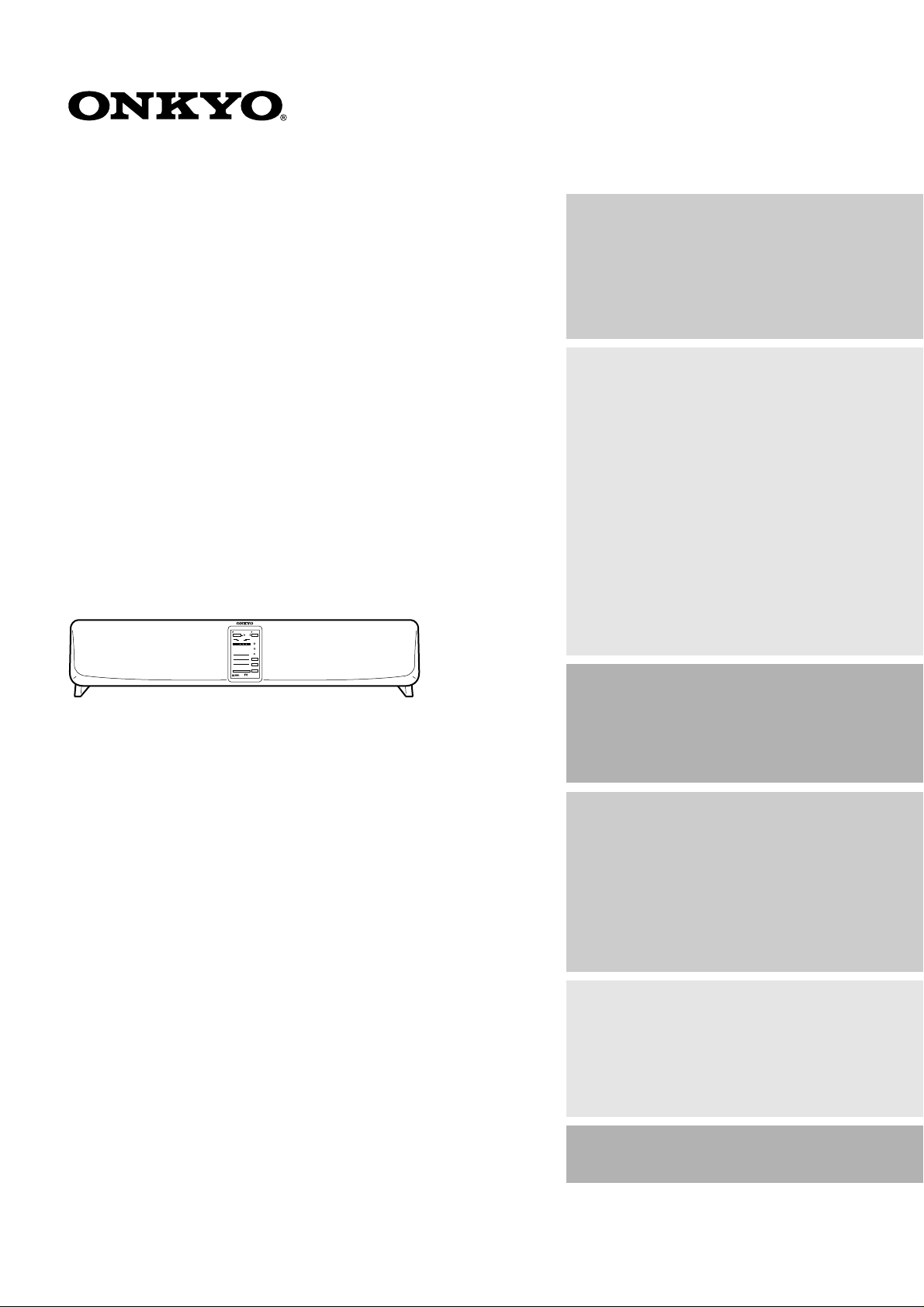
PHC-5
Virtual Surround Unit PHC-5
Instruction Manual
(for European model)
STANDBY/ON POWER
OFF
ON
PANORAMA
WIDE
TV
VIDEO
NORMAL
DISTANCE
AUX
NEAR
INPUT
MID
FAR
VOLUME
LEVEL MAXMIN
VIRTUAL
PHC-5
Therter-Dimensional
SURROUND
Contents
Important Safeguards......................... 2
Precautions........................................... 3
Features................................................ 3
Package Contents................................4
Checking the package contents.............. 4
Installing batteries.................................. 4
Installation...........................................5
Installation Precautions.......................... 6
Connections.......................................... 7
Connecting to the TV (IPM system)...... 7
Connecting the subwoofer, SKW-320,
SKW-310, etc. .................................... 8
Connecting to
VIDEO/AUX INPUT jacks................ 8
Connecting the power cord.................... 9
Turning on the power to the PHC-5 system9
Before Operating the PHC-5
System..............................................10
Using the remote controller ................. 10
Adjusting the angle of the unit............. 10
Operating the PHC-5 System........... 11
Compatible recordings and media ....... 11
Using the Virtual Surround system
for TV sound..................................... 11
Other functions .................................... 14
Thank you for purchasing the Onkyo Phantom Cinema.
Please read this manual thoroughly before making
connections and turning on the power.
Following the instructions in this manual will enable
you to obtain optimum performance and listening
enjoyment from your new Phantom Cinema.
Please retain this manual for future reference.
Programmable Remote Controller.. 15
Notes on programming the remote con-
troller:................................................ 15
Buttons used for programming ............ 15
Programming the other remote
controller’s function.......................... 16
Checking the programmed functions... 17
Erasing all programmed functions....... 17
Parts and Names................................ 18
Virtual Surround Unit PHC-5
(front panel) ...................................... 18
Virtual Surround Unit PHC-5
(rear panel)........................................ 18
Remote controller RC-382M ............... 19
Troubleshooting................................. 20
Specifications..................................... 20
Page 2
1.
WARNING:
TO REDUCE THE RISK OF FIRE OR ELECTRIC SHOCK,
DO NOT EXPOSE THIS APPLIANCE TO RAIN OR
MOISTURE.
CAUTION:
TO REDUCE THE RISK OF ELECTRIC SHOCK, DO NOT
REMOVE COVER (OR BACK). NO USER-SERVICEABLE
PARTS INSIDE. REFER SERVICING TO QUALIFIED
SERVICE PERSONNEL.
Important Safeguards
12.
Read Instructions – All the safety and operating instructions
should be read before the appliance is operated.
2.
Retain Instructions
should be retained for future reference.
3.
Heed Warnings
operating instructions should be adhered to.
4.
Follow Instructions
should be followed.
5.
Water and Moisture
water – for example, near a bathtub, washbowl, kitchen sink,
laundry tub, in a wet basement, or near a swimming pool, and
the like.
6.
Carts and Stands
ance should be used only with a
cart or stand that is recommended by the manufacturer.
6A. An appliance and cart combina-
tion should be moved with care.
Quick stops, excessive force,
and uneven surfaces may cause
the appliance and cart combination to overturn.
7.
Wall or Ceiling Mounting
to a wall or ceiling only as recommended by the manufacturer.
8.
Ventilation
tion or position does not interfere with its proper ventilation.
For example, the appliance should not be situated on a bed,
sofa, rug, or similar surface that may block the ventilation
openings; or if placed in a built-in installation, such as a bookcase or cabinet that may impede the flow of air through the
ventilation openings, there should be free space of at least
20 cm (8 in.) and an opening behind the appliance.
9.
Heat
sources such as radiators, heat registers, stoves, or other appliances (including amplifiers) that produce heat.
10.
Power Sources –
power supply only of the type described in the operating
instructions or as marked on the appliance.
11.
Polarization
plug having one blade wider than the other, please read the following information:
The polarization of the plug is a safety feature. The polarized
plug will only fit the outlet one way. If the plug does not fit
fully into the outlet, try reversing it. If there is still trouble, the
user should seek the services of a qualified electrician. Under
no circumstances should the user attempt to defeat the polarization of the plug.
– The appliance should be situated so that its loca-
– The appliance should be situated away from heat
– The safety and operating instructions
– All warnings on the appliance and in the
– All operating and use instructions
– The appliance should not be used near
– The appli-
The appliance should be connected to a
– If the appliance is provided with a polarized
PORTABLE CART WARNING
S3125A
– The appliance should be mounted
Power-Cord Protection
routed so that they are not likely to be walked on or pinched by
items placed upon or against them, especially near plugs, convenience receptacles, and the point where they exit from the
appliance.
13.
Cleaning
mended by the manufacturer.
14.
Nonuse Periods
unplugged from the outlet when left unused for a long period
of time.
15.
Object and Liquid Entry
objects do not fall and liquids are not spilled into the enclosure
through openings.
16.
Damage Requiring Service
viced by qualified service personnel when:
A. The power-supply cord or the plug has been damaged; or
B. Objects have fallen, or liquid has been spilled into the
C. The appliance has been exposed to rain; or
D. The appliance does not appear to operate normally or
E. The appliance has been dropped, or the enclosure damaged.
17.
Servicing
ance beyond that described in the operating instructions. All
other servicing should be referred to qualified service personnel.
Memory Preservation
This unit does not require memory preservation batteries.
A built-in memory power back-up system preserves the
contents of the memory during power failures and even
when the unit is unplugged. The unit must be plugged in
order to charge the back-up system.
The memory preservation period after the unit has been
unplugged varies depending on climate and placement of
the unit. On the average, memory contents are protected
over a period of a few weeks after the last time the unit
has been unplugged. This period is shorter when the unit
is exposed to a highly humid climate.
WARNING
RISK OF ELECTRIC SHOCK
DO NOT OPEN
The lightning flash with arrowhead symbol, within an equilateral
triangle, is intended to alert the user to the presence of uninsulated
“dangerous voltage” within the product’s enclosure that may be of
sufficient magnitude to constitute a risk of electric shock to persons.
The exclamation point within an equilateral triangle is intended to
alert the user to the presence of important operating and maintenance
(servicing) instructions in the literature accompanying the appliance.
– Power-supply cords should be
– The appliance should be cleaned only as recom-
– The power cord of the appliance should be
appliance; or
exhibits a marked change in performance; or
– The user should not attempt to service the appli-
AVIS
RISQUE DE CHOC ELECTRIQUE
– Care should be taken so that
– The appliance should be ser-
OUVRIR
NE PAS
2
Page 3

■
■
■
■
Precautions
1. Warranty Claim
You can find the serial number on the rear panel of this unit. In
case of warranty claim, please report this number.
2. AC Fuse
The fuse is located inside the chassis and is not user-serviceable. If power does not come on, contact your Onkyo authorized service station.
3. Care
From time to time you should wipe the front and rear panels and
the cabinet with a soft cloth. For heavier dirt, dampen a soft
cloth in a weak solution of mild detergent and water, wring it
out dry, and wipe off the dirt. Following this, dry immediately
with a clean cloth. Do not use rough material, thinners, alcohol
or other chemical solvents or cloths since these could damage
the finish or remove the panel lettering.
4. Power WARNING
BEFORE PLUGGING IN THE UNIT FOR THE FIRST TIME,
READ THE FOLLOWING SECTION CAREFULLY.
The voltage of the available power supply differs according to
•
country or region. Be sure that the power supply voltage in the
area where this unit will be used meets the required voltage (e.g.,
AC 230 V, 50 Hz) written on the rear panel.
For British model
Replacement and mounting of an AC plug on the power supply
cord of this unit should be performed only by qualified service
personnel.
IMPORTANT
The wires in the mains lead are coloured in accordance with the
following code:
Blue : Neutral
Brown: Live
As the colours of the wires in the mains lead of this apparatus
may not correspond with the coloured markings identifying the
terminals in your plug, proceed as follows:
The wire which is coloured blue must be connected to the terminal which is marked with the letter N or coloured black.
The wire which is coloured brown must be connected to the terminal which is marked with the letter L or coloured red.
IMPORTANT
A 5 amp fuse is fitted in this plug. Should the fuse need to be
replaced, please ensure that the replacement fuse has a rating of
5 amps and that it is approved by ASTA or BSI to BS1362.
Check for the ASTA mark or the BSI mark on the body of the
fuse.
IF THE FITTED MOULDED PLUG IS UNSUITABLE FOR
THE SOCKET OUTLET IN YOUR HOME THEN THE FUSE
SHOULD BE REMOVED AND THE PLUG CUT OFF AND
DISPOSED OF SAFELY. THERE IS A DANGER OF
SEVERE ELECTRICAL SHOCK IF THE CUT OFF PLUG IS
INSERTED INTO ANY 13 AMP SOCKET.
If in any doubt, please consult a qualified electrician.
Features
Onkyo’ s Theater -Dimensional Sound
Theater-Dimensional Virtual Surround system developed
by Onkyo creates the optimum home theater environment
by adjusting the listening distance and the width of the
sound output from the front speakers.
Onkyo’s Intelligent Power Management System
(IPM)
Onkyo’s intelligent power management system (IPM)
turns on/off the complete system, automatically (audio
triggered), simply by turning on/off the television.
OMF cone
Onkyo Micro Fiber (OMF) Speaker Cones, a major
advancement in speaker design developed exclusively by
Onkyo, use a light-weight silk fiber to greatly improve
the damping coefficient — the result is clearly separated
fundamental second and third harmonics, superior ambiance and a much more accurate, natural sound.
Easy-to-setup and Easy-to-use home theater system
Connecting this unit to your TV enables you to enjoy
home theater environment. Program the remote controller
functions of your TV or VCR into the PHC-5’s remote
controller (included in the package) for much easier operation.
Declaration of Conformity
We,
ONKYO EUROPE
ELECTRONICS GmbH
INDUSTRIESTRASSE 20
82110 GERMERING,
GERMANY
declare in own responsibility, that the ONKYO product described
in this instruction manual is in compliance with the corresponding
technical standards such as EN55013, EN55020, EN61000-3-2, -3-3
and EN60065
GERMERING, GERMANY
K.OTSU
ONKYO EUROPE ELECTRONICS GmbH
3
Page 4
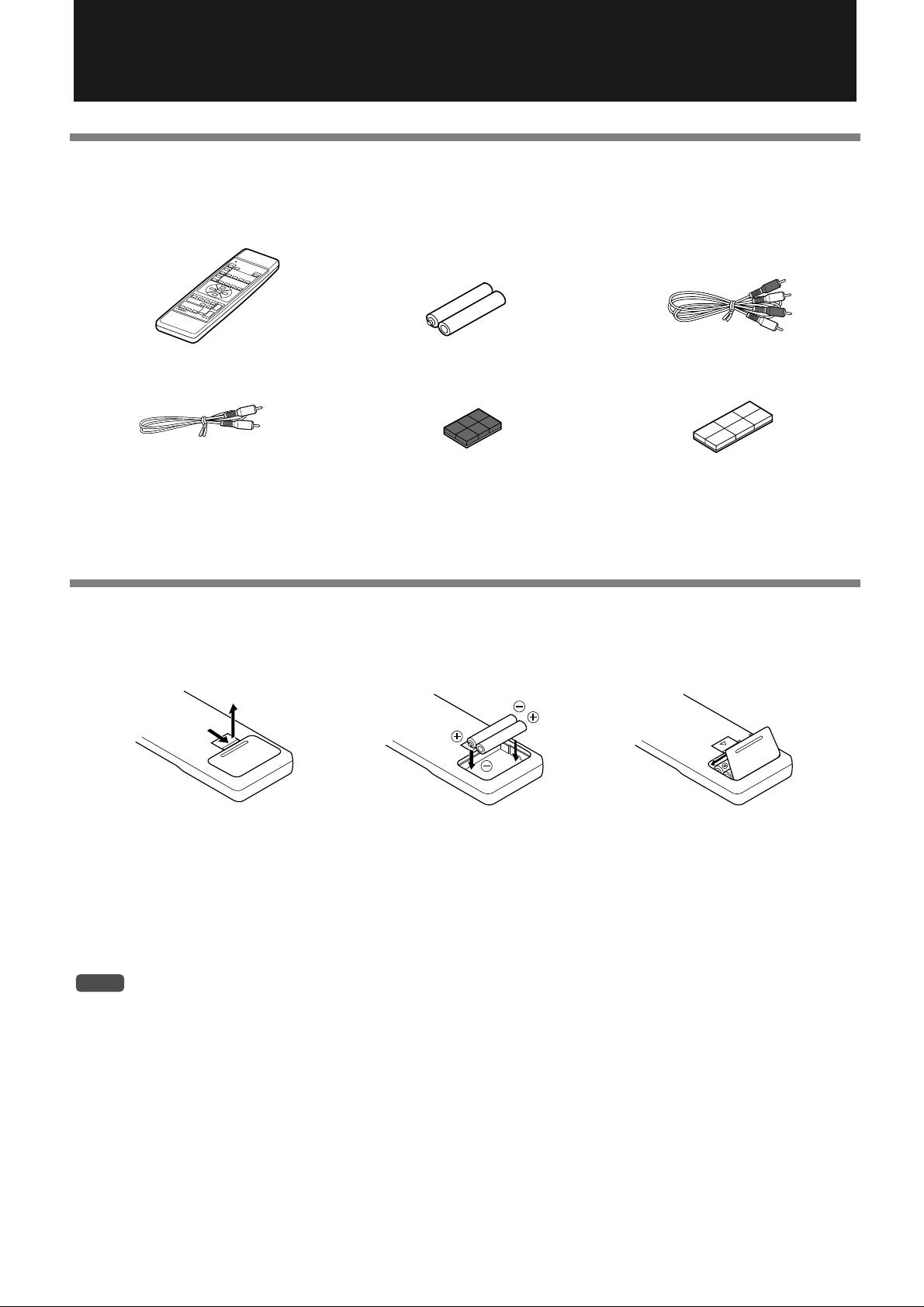
Package Contents
Checking the package contents
Before using this product, make sure that the package includes the following items:
● Remote controller (RC-382M) × 1 ● Batteries (AA) × 2 ● Stereo audio connection cable × 1
R
E
M
O
T
E
C
O
N
T
R
O
L
L
E
R
● Monaural audio connection ● Dual-side fixing tape (white) × 1● Anti-slippage pad (black) × 1
cable × 1
● Instruction manual (this book) × 1 ● Quick guide × 1
Installing batteries
Insert two batteries (included in the package) into the remote controller as shown below.
123
Pull up the battery compartment cover in the direction
of the arrow to remove it.
Insert two AA-size batteries
into the battery compartment. Carefully follow the
polarity diagram (positive
(+) and negative (–) symbols) inside the battery
compartment.
Replace the battery compartment cover.
4
NOTE
•
Do not mix battery types. Do not use a new battery and an old battery at the same time.
•
If you do not plan to use the remote controller for a long period of time, remove the batteries from the compartment to prevent battery liquid from leaking.
•
Leaving dead batteries inside the compartment for an extended period may cause corrosion, which may damage the remote controller. I f
the unit does not respond well to remote control operation, replace the old batteries with new ones immediately.
•
The life of the included manganese batteries is about six months, although it depends on how often you use the remote controller. Onkyo
recommends that you use alkaline AA (LR6 or AM-3)-size batteries for replacement.
Page 5
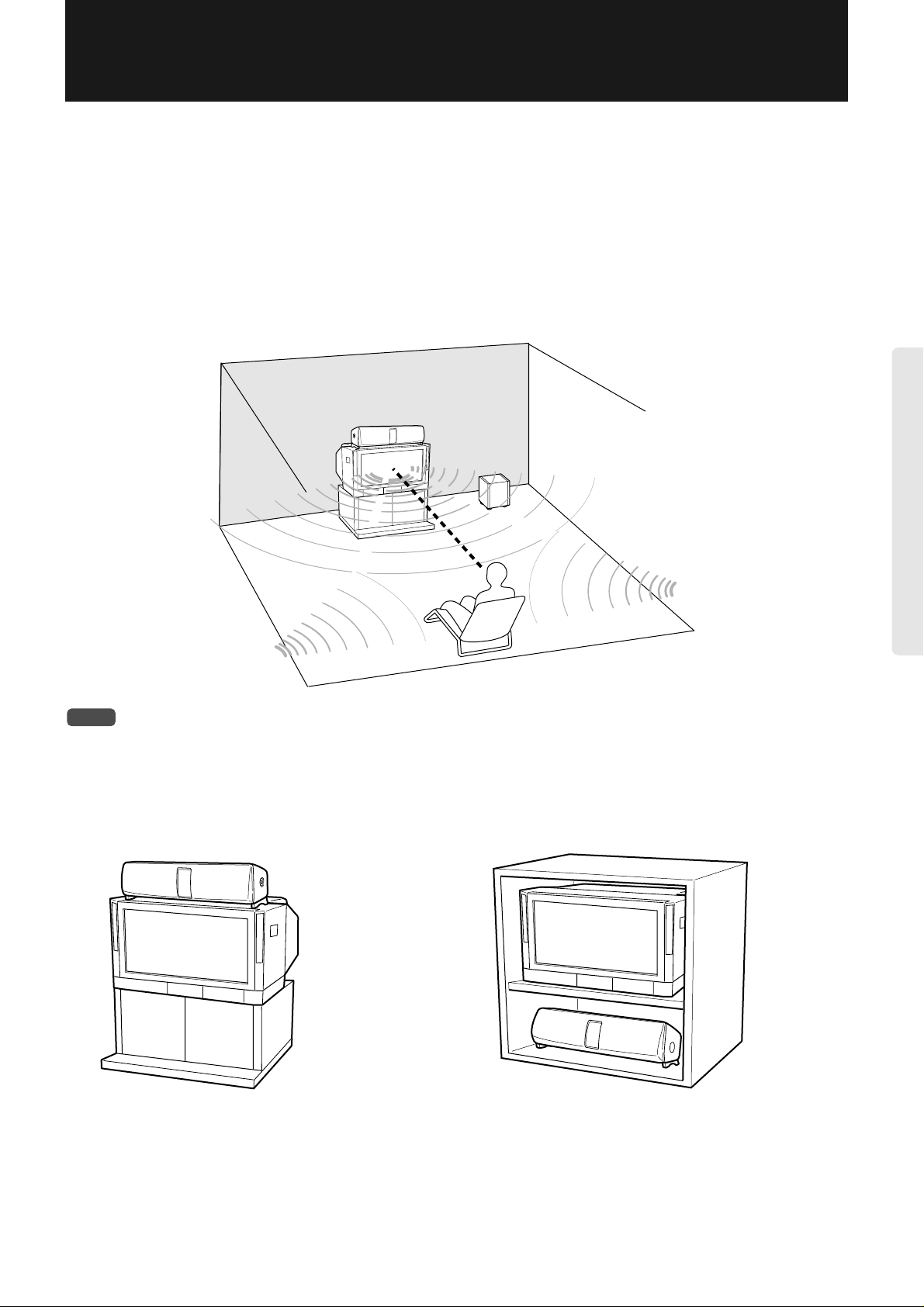
Installation
W e can usually identify the source of a sound based on its loudness and the time difference (delay) between the sound reaching
our left ear and right ear. The Virtual Surround system of this unit uses this characteristic of human hearing. This system, along
with the DSP (Digital Signal Processor) technology, creates an effect that makes you think the sound is coming from all around
you, even though the sound is output from only two front speakers. The Virtual Surround system limits the sweet spot (effective listening position) due to its nature. That is, the Virtual Surround system of this unit sets an optimum listening position at
any point on the center axis when you face the unit. Any position not on the axis will have less effect. Also, if the room has
many objects that reflect sound or that cause uneven reflection, the optimum effect may not be obtained.
The effect of the subwoofer varies significantly depending on its location. Generally, placing the subwoofer in the corner of the
room would be the most effective.
Installation example
PHC-5
Subwoofer
Center
axis
NOTE
•
T o pre v ent the cabinet from deforming or discoloration, av oid locations which are e xposed to direct sunlight or much humidity, or close to
an air conditioning unit or heater.
Onkyo SKW-320, SKW-310, etc.
Placing the unit on the TV Placing the unit under the TV
5
Page 6
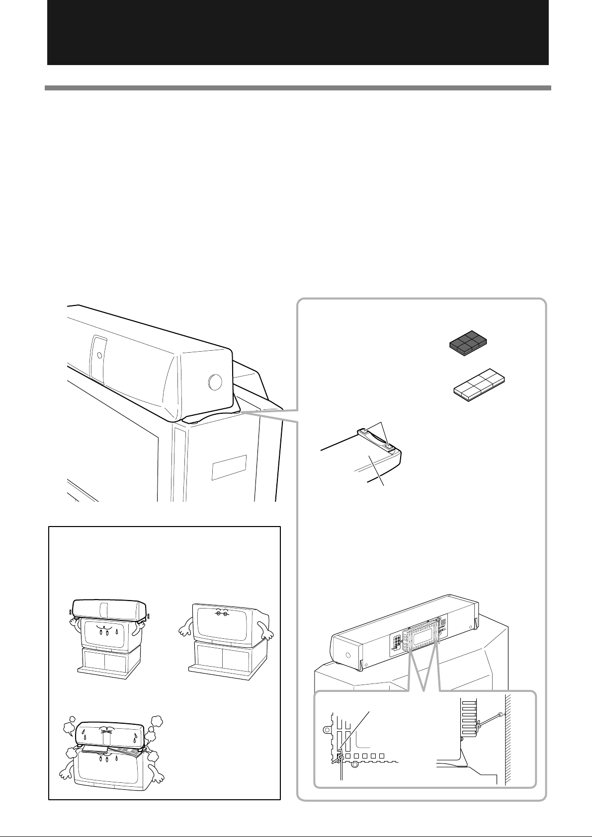
Installation (continued)
Installation Precautions
Install the unit on a level, stable surface. The unit may fall if you install it on a tilted or unstable surface.
Follow the requirements below to place the unit on top of a TV:
The TV surface on the top side is larger than the bottom surface of the unit.
•
The TV surface is level and not tilted.
•
The TV is not on an unstable surface.
•
To prevent the PHC-5 from falling, be sure to attach the anti-slippage pads (included in the package) on the bottom of the unit,
and use a strong rope to fix the unit against the wall for safety, as shown in the figure.
If you cannot fix the unit using a rope, attach the dual-sided fixing tape (included in the package) to the bottom of the PHC-5 to
fix the unit to the TV.
Note 1: The dual-sided fixing tape (white) uses strong adhesive. It will be v ery dif ficult to remo v e the tape once it is attached to
the surface.
Note 2: Make sure that the surface on which you wish to attach the anti-slippage pad or tape is not dirty or wet. Otherwise, the
pad or tape will not be fixed to the surface.
Do not place the unit in the following
locations:
Where the width of the TV
is narrower than the unit.
Where the top surface
of the TV is tilted.
●Attaching anti-slippage pads or dual-sided fixing tape
Anti-slippage pads (black)
Dual-sided fixing tape (white)
Anti-slippage pads
Attach the included anti-slippage
pads in the left and right corners
on the bottom of the unit as
shown in the figure. If the unit
can not be secured with the pads,
Bottom of the unit
attach the dual-sided fixing tape
on top of the pads.
Secure the unit against the wall using a
strong rope to prevent the unit fr om falling.
(Be sure to secure the unit against the wall
at two places.)
6
Where the vent holes on the
bottom of the unit are blocked.
Use this slot to
tighten the rope.
Wall
PHC-5
TV
Page 7

Do not plug the power cord into the AC
Connections
outlet until all connections are completed.
Connecting to the TV (IPM system)
•
Use the cable included in the package for connection. Connect the stereo audio connection cable as follows:
To TV’s audio output L ch. jack...white
To TV’s audio output R ch. jack...red
•
Plug the cables securely. Incomplete connection may cause noise or malfunction.
•
Refer to the manual for your TV or VCR for more information on AV output connections.
CAUTION
Be sure to connect fixed output to the “Fixed” audio output jacks. For variable output, refer to the manual for your TV to turn the internal
•
speakers off.
Lower the volume level on the PHC-5 before you change an input source using the INPUT SELECTOR, since the input level of a device
connected to the VIDEO or AUX input jacks may be different from the input level of the TV and selecting a different input source may
produce a loud sound.
Some TVs may output audio signals even if the po wer is turned off. If such a TV is connected to a VCR that is programmed for recording,
•
the IPM system may be enabled. To make sure that the IPM system is disabled, turn off the POWER switch on the PHC-5 or connect the
TV output to the VIDEO or AUX input jacks. Refer to the “Connecting to VIDEO/AUX INPUT jacks” section on the next page.
white...PHC-5’s TV input L ch. jack
red...PHC-5’s TV input R ch. jack
What is IPM (Intelligent Power Management) system?
If the TV audio output is connected to the unit’s TV in jacks, turning on (off)
the power to the TV will automatically turn on (of f) the po wer to the unit. This
is called the “IPM system.”
PHC-5
rear panel
PHC-5
STANDBY/ON POWER
OFF
ON
PANORAMA
WIDE
TV
VIDEO
NORMAL
DISTANCE
AUX
NEAR
INPUT
MID
FAR
VOLUME
LEVEL MAXMIN
VIRTUAL
SURROUND
TV
PHC-5
Therter-Dimensional
Read the
“CAUTION”
described
above.
Audio Output
Variable
L
R
Fixed
L
R
Improper connection
Insert completely
*Be sure to connect fixed
output to the “Fixed” audio
output jacks. For variable
output, refer to the manual for your TV to turn the
internal speakers off.
*If you have a video cassette
recorder, connect it to the Audio
Input on the TV or INPUT VIDEO
Video Cassette Recorder
: Signal flow
Audio Input
L
R
Audio Output
L
R
jack on the PHC-5.
NOTE
When you listen to the TV sound through the unit, turn down the TV volume to minimum. Sound coming from the TV itself may reduce
•
the surround effect.
7
Page 8

Connections (continued)
Connecting the subwoofer, SKW-320, SKW-310, etc.
Connect the subwoofer Optional Onkyo subwoofer SKW-320, SKW-310, etc. to the SUBWOOFER PREOUT jack on the PHC-5.
We recommend y ou connect a subw oofer to take the best ad v antage of the virtual
surround effects.
–
–
–
–
Subwoofer with built-in
: Signal flow
amplifier (active)
(SKW-320,
SKW-310, etc.)
LINE INPUT
L
R
• You may connect the cable to either L or R
Included
Monaural audio connection cable
STANDBY/ON POWER
OFF
ON
PANORAMA
WIDE
TV
VIDEO
NORMAL
DISTANCE
AUX
NEAR
INPUT
MID
FAR
VOLUME
LEVEL MAXMIN
VIRTUAL
PHC-5
Therter-Dimensional
SURROUND
input, if applicable.
PHC-5
TIP
You can connect any subwoofer with a crossover frequency between 100Hz and 200Hz. Place the subwoofer in the optimum position.
•
The location of the subwoofer significantly changes the effects. In most cases, place it in the corner of the room to get the best results.
•
Refer to the instruction manual that came with the subwoofer for more information.
•
Connecting to VIDEO/AUX INPUT jacks
Use the VIDEO or AUX input jacks for connection in the following cases:
To connect another audio or video device.
Lower the volume level on the PHC-5 before you change an input source using the INPUT SELECTOR, since the input
level of a device such as CD player connected to the VIDEO or AUX input jacks may be different from the input level of the
TV and selecting a different input source may produce a loud sound.
To connect your VCR directly to the PHC-5, since your TV does not have audio output jacks.
T o connect your VCR directly to the PHC-5, since your TV has “variable” audio output jacks. (Refer to the “CAUTION” on
page 7.)
T o connect your VCR directly to the PHC-5, since your TV outputs audio signals during programmed recording on the VCR
even if the power to the TV is turned off. (Refer to the “CAUTION” on page 7.)
•
Use the cable included in the device for connection. Connect the stereo audio connection cable as follows:
To the audio output L ch. jack of the device...white
To the audio output R ch. jack of the device...red
•
Plug the cables securely. Incomplete connection may cause noise or malfunction.
•
Refer to the manual for your AV device for more information on AV output connections.
: Signal flow
CD player, MD player etc.
VCR, LD player or DVD player etc.
8
Audio Output
L
R
Audio Output
L
R
white...PHC-5’s AUX or VIDEO input L ch. jack
red...PHC-5’s A UX or VIDEO input R ch. jack
STANDBY/ON POWER
OFF
ON
PANORAMA
WIDE
TV
VIDEO
NORMAL
DISTANCE
AUX
NEAR
INPUT
MID
FAR
LEVEL MAXMIN
VOLUME
VIRTUAL
PHC-5
Therter-Dimensional
SURROUND
PHC-5
Page 9

Connecting the power cord
Follow the instructions below to connect the power cord:
• Make sure that all connections other than the power cord for the PHC-5 system have already been made.
• Turning on the power to the PHC-5 system may cause a very brief current surge that might affect other devices, such as a
computer, if they are on the same circuit. Connect those devices to another circuit of the AC outlet.
PHC-5
STANDBY/ON POWER
STANDBY/ON POWER
OFF
ON
OFF
ON
PANORAMA
WIDE
TV
PANORAMA
WIDE
TV
VIDEO
NORMAL
VIDEO
NORMAL
DISTANCE
AUX
DISTANCE
NEAR
AUX
INPUT
NEAR
MID
INPUT
MID
FAR
FAR
VOLUME
LEVEL MAXMIN
LEVEL MAXMIN
VOLUME
VIRTUAL
PHC-5
Therter-Dimensional
SURROUND
VIRTUAL
PHC-5
Therter-Dimensional
SURROUND
to the wall outlet
Turning on the power to the PHC-5 system
Press the POWER switch on the PHC-5 to turn the power on.
The STANDBY/ON indicator lights up.
Press the POWER switch again to turn the power off.
POWER switch
ST ANDBY/ON POWER
OFF
The STANDBY
indicator
P ANORAMA
WIDE
NORMAL
DISTANCE
ON
TV
VIDEO
AUX
NEAR
MID
INPUT
FAR
LEVEL MAXMIN
VOLUME
VIRTUAL
SURROUND
Theater-Dimensional
PHC-5
NOTE
Turn off the power to the PHC-5 if you do not use them for a long period of time.
PHC-5
STANDBY/ON POWER
STANDBY/ON POWER
OFF
ON
OFF
ON
PANORAMA
WIDE
TV
PANORAMA
WIDE
TV
VIDEO
NORMAL
VIDEO
NORMAL
DISTANCE
AUX
DISTANCE
NEAR
AUX
INPUT
NEAR
MID
INPUT
MID
FAR
FAR
LEVEL MAXMIN
VOLUME
VOLUME
LEVEL MAXMIN
VIRTUAL
PHC-5
Therter-Dimensional
SURROUND
VIRTUAL
PHC-5
Therter-Dimensional
SURROUND
9
Page 10

Before Operating the PHC-5 System
Using the remote controller
Point the remote controller toward the remote control sensor panel on the unit. Operate the remote controller within the angle
and distance specified in the figure below.
The STANDBY indicator lights
up when the unit receives a signal from the remote controller.
STANDBY/ON POWER
OFF
ON
Remote control sensor
30˚
R
E
M
O
T
E
C
O
N
T
R
O
L
L
E
R
30˚
Remote controller
RC-382M
within approx. 5m
NOTE
• Do not let strong light, such as direct sunlight or an inverter fluorescent light, strike the remote control sensor panel.
• Do not use the unit with a different remote controller. Otherwise, a malfunction may occur.
• Do not place any object, such as a book, on the remote controller. Otherwise, a button on the remote controller may be held down, which
will waste the batteries.
• An object between the remote controller and the sensor panel on the unit may prevent the remote controller from working.
Adjusting the angle of the unit
You can adjust the angle of the PHC-5 vertically (upward: about 20 degrees; downward: about 10 degrees). Adjust the angle
according to the height of your ears.
Upward: about 20 degrees
Downward:
about 10 degrees
Cap
If the pivot of the unit is too
tight (or too loose) to rotate,
remove the caps and loosen
(or tighten) the screws using
a Phillips screwdriver.
Be sure to use both hands to
adjust the angle of the unit to
Adjust the angle of the PHC-5
vertically according to the height
of your ears.
prevent it from falling.
10
Page 11

Operating the PHC-5 System
VOLUME
LEVEL MAXMIN
π: Raise the volume level.
†: Lower the volume level.
VOLUME
Light up
PHC-5
Compatible recordings and media
• The Virtual Surround system on the PHC-5 system produces the best effect with recordings (media) that use the “Dolby*
Surround” system. These media include Hi-Fi VHS, laser discs, and DVD video, which carry the mark. The
Virtual Surround system also produces a great effect with normal stereo recordings, although some of them may seem to
have a narrower stereo image or produce unnatural sound. In this case, use Stereo mode.
• Some stereo recordings use special recording techniques or special processing, such as virtual processing. The Virtual Surround
system may sometimes over-enhance or reduce the ef fect too greatly with these recordings. In this case, use Stereo mode.
• The Virtual Surround system produces no effect with monaural recordings.
*Manufactured under license from Dolby Laboratories.
“Dolby” and the double-D symbol are trademarks of Dolby Laboratories.
Using the Virtual Surround system for TV sound
Lower the TV volume level to minimum and turn on the po wer to the PHC-5
DOLBY SURROUND
PRO • LOGIC
SENDING/
LEARNED
DISPLAY LEARN
POWER
POWER
TV/VCR
POWER
TV/VIDEO
DISTANCE EXPAND
SURROUND
VOLUME
VIDEO CONTROL
TV CONTROL
CH
MODE
SUB
1 Turn on the power to the TV.
About three seconds after the TV sends out the audio signal, the power is
turned on to the PHC-5 (IPM function), and the STANDBY/ON indicator
turns off. The “TV” indicator in the “TV/VIDEO/AUX” section lights up.
NEAR
MID
PANORAMA
WIDE
NORMAL
DISTANCE
TV
VIDEO
AUX
INPUT
TIP
To listen to the audio of a device connected to the VIDEO/AUX
jack, press the ST ANDBY/ON b utton on the unit or the POWER
button on the remote controller, then press the INPUT button on
the unit or the INPUT SELECTOR button on the remote controller to turn the “VIDEO” or “AUX” indicator on.
2 Adjust the volume level.
PHC-5
INPUT
FRONT BALANCE
INPUT SELECTOR
VIDEO
TV
REMOTE CONTROLLER
VOLUME
AUX
MUTING
RC-382M
When you operate one of the VOLUME buttons (either on the unit or on the
remote controller), the LEVEL meter lights up, indicating the current level.
The LEVEL meter turns off five seconds after you release the button.
(Continued to the next page)
11
Page 12

Operating the PHC-5 System (continued)
3 On the remote controller, select Virtual mode by
pressing the MODE button.
SENDING/
LEARNED
DISPLAY LEARN
POWER
POWER
TV/VCR
POWER
TV/VIDEO
DISTANCE EXPAND
SURROUND
FRONT BALANCE
INPUT SELECTOR
VIDEO
TV
REMOTE CONTROLLER
VOLUME
VIDEO CONTROL
MODE
SUB
AUX
TV CONTROL
CH
MUTING
VOLUME
RC-382M
MODE
NEAR
MID
PANORAMA
WIDE
NORMAL
DISTANCE
TV
VIDEO
AUX
INPUT
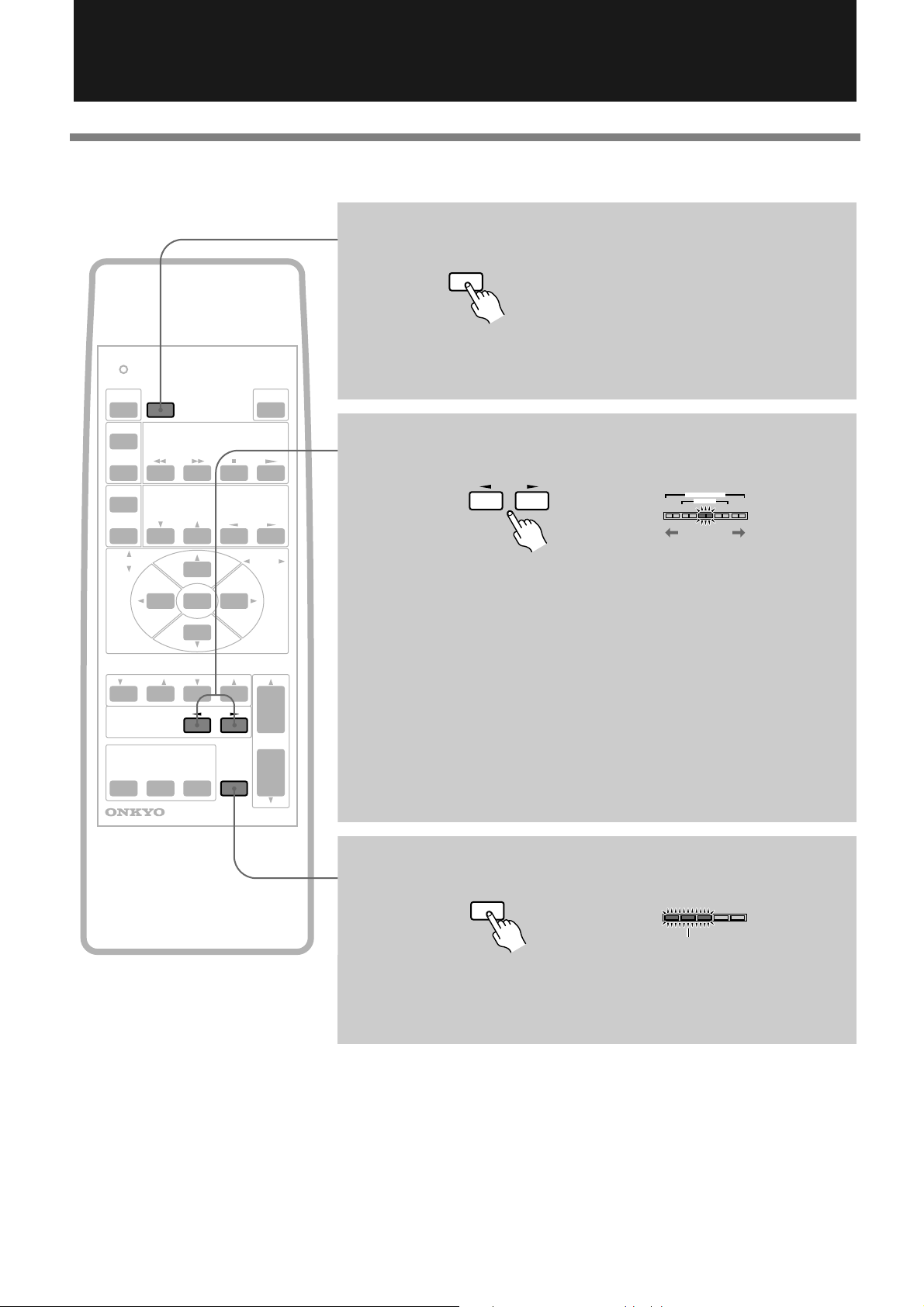
Pressing the MODE button repeatedly toggles between Virtual mode and
Stereo mode.
If you select Stereo mode, skip to Step 7 on the next page.
4 Set the listening distance (distance between the lis-
tener and the unit) using the DISTANCE π/† buttons.
DISTANCE EXPAND
MODE
NEAR
MID
FAR
π: Press this button when the listening position is closer to the unit.
†: Press this button when the listening position is far from the unit.
NEAR (1.2m) ↔ MID (1.8m) ↔ FAR (2.4m or more)
(short) (medium) (long)
* This distance is a guideline. Adjust the distance while listening to the
sound.
The mark lights up on the display of the unit, indicating the distance.
. . .
NEAR (1.2m)
. . .
MID (1.8m)
. . .
FAR (2.4m or more)
12
5 Use the EXPAND √/® buttons on the remote con-
troller to adjust the width of the sound.
PANORAMA
DISTANCE EXPAND
MODE
√: Press this button to reduce the width.
®: Press this button to expand the sound field.
WIDE
NORMAL
PANORAMA
WIDE
NORMAL
PANORAMA
WIDE
NORMAL
(PANORAMA)
(WIDE)
(NORMAL)
Page 13

SENDING/
SURROUND
LEVEL MAXMIN
π: Press this button to raise
the surround sound.
†: Press this button to lower
the surround sound.
When you press the †SURROUNDπ
button, the LEVEL meter lights up,
indicating the current volume level.
The meter turns off about five seconds
after you release the button.
SUB
LEVEL MAXMIN
π:Press this button to raise the
sound from the subwoofer.
†:Press this button to lower the
sound from the subwoofer.
When you press the †SUBπ button,
the LEVEL meter lights up, indicating
the current volume level.
The meter turns off about five seconds
after you release the button.
POWER
LEARNED
DISPLAY LEARN
POWER
6 Adjust the volume level of the surround sound.
POWER
TV/VCR
POWER
TV/VIDEO
DISTANCE EXPAND
SURROUND
FRONT BALANCE
INPUT SELECTOR
VIDEO
TV
REMOTE CONTROLLER
VOLUME
VIDEO CONTROL
MODE
SUB
AUX
TV CONTROL
CH
MUTING
If a subwoofer has been connected:
7 Adjust the volume level of the subwoofer.
VOLUME
RC-382M
After watching the TV, turn off the power to the TV.
About five minutes after you turn off the power to the TV, the power to the unit
is turned off, and the STANDBY indicator lights up.
NOTE
• If you press the INPUT button on the unit or the INPUT SELECTOR button on the
remote controller to select an input source other than the TV after you turn off the
power to the TV, the IPM function will be cancelled and the power to the PHC-5 will
not be turned off after five minutes. (If you have selected VIDEO or AUX, the IPM
function will be also cancelled and the power to the PHC-5 will remain turned on.)
• If you do not use the unit for a long period of time, turn off the POWER switch on the
unit. (See page 9.)
To turn on/off the power to the unit without turning on/
off the power to TV:
Press the POWER button on the remote controller.
13
Page 14
Operating the PHC-5 System (continued)
DISPLAY
FRONT BALANCE
NORMAL
WIDE
PANORAMA
The sound pans
The sound pans
to the right.
to the left.
MUTING
LEVEL MAXMIN
Flash
Other functions
Turning off the light on the display
SENDING/
LEARNED
DISPLAY LEARN
POWER
POWER
TV/VCR
POWER
TV/VIDEO
DISTANCE EXPAND
SURROUND
FRONT BALANCE
INPUT SELECTOR
VIDEO
TV
REMOTE CONTROLLER
VOLUME
VIDEO CONTROL
MODE
SUB
AUX
TV CONTROL
CH
MUTING
VOLUME
RC-382M
Pressing the DISPLAY button turns on/off the light on the display of the unit.
This button is disabled in Stereo mode.
Adjusting the balance
√: Press this button to shift the sound to the left.
®: Press this button to shift the sound to the right.
Note on adjusting the balance:
In Virtual Surround mode, set the balance in the center position and do not
adjust it. Shifting the sound in this mode may impair the Virtual Surround
effect.
• The PHC-5 remembers the balance setting in Stereo mode after you turn off
the power to the unit. However, if you change to Virtual Surround mode, the
balance setting is automatically reset to the center. Also, any balance setting
made in Virtual Surround mode will be reset to the center after you turn off
the power to the unit.
14
Muting the sound
Press the MUTING button to mute the sound. Press the button again or press the
VOLUME buttons (VOLUME†/π) to cancel muting.
• The LEVEL meter flashes during mute.
Page 15
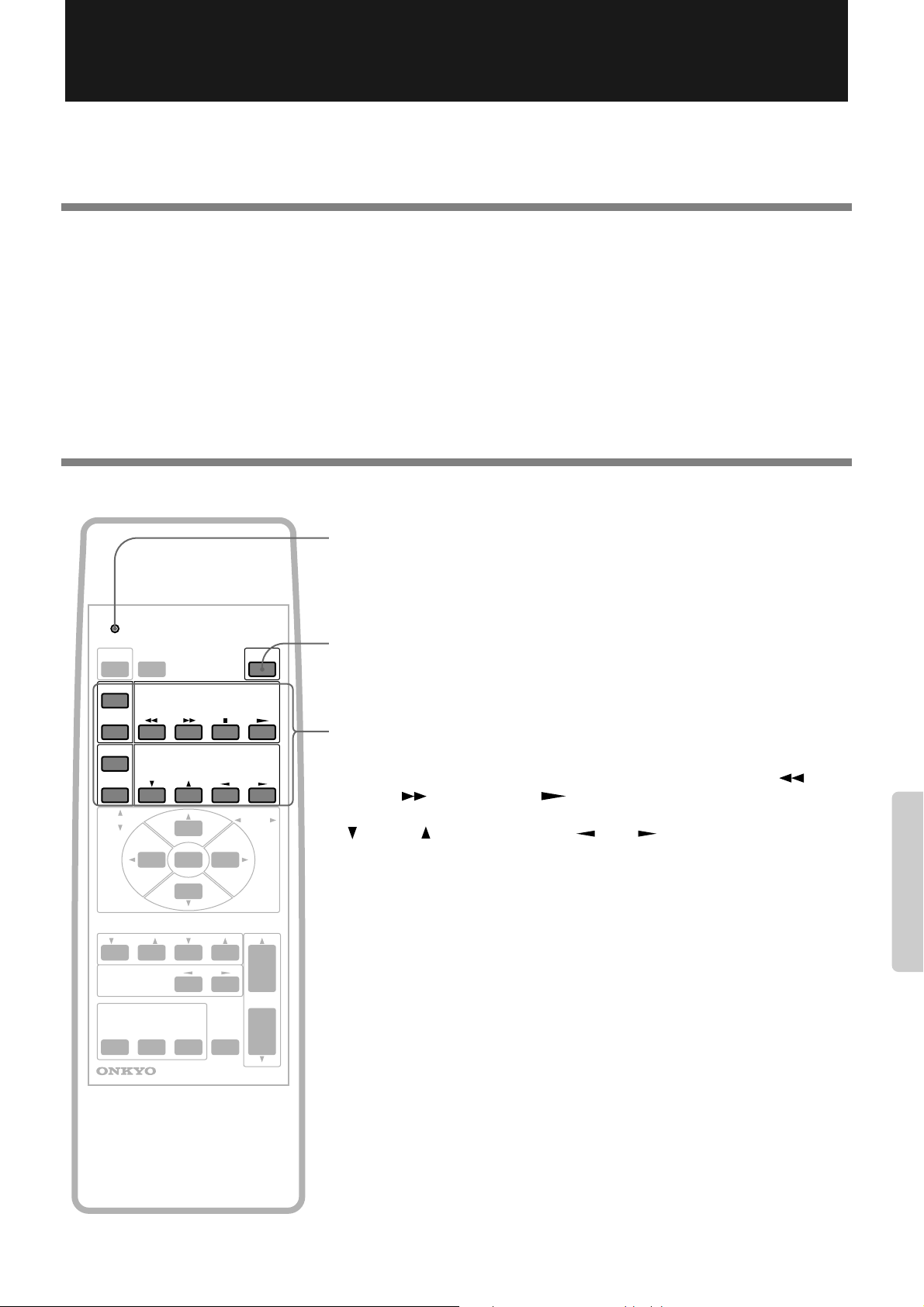
Programmable Remote Controller
You can use the remote controller RC-382M to remotely control a TV or VCR by programming the functions of the remote
controller for the device into the RC-382M.
Notes on programming the remote controller:
• Use new batteries for the RC-382M and the remote controller for a TV or VCR. Using old batteries may result in a failure in
programming or cause the programmed remote controller buttons to work incorrectly.
• The RC-382M uses infrared rays, like most other remote controllers. The RC-382M may be unable to program other remote
controllers that use different technology.
• The RC-382M has twelve buttons for programming. The number of items you can store in these buttons depends on the
manufacturer of the remote controller and the type of the devices you wish to program into the RC-382M. (Some remote
controllers allow you to program only one or two functions.) Program the desired functions to suit your preference.
• When you are programming the functions of the other device into the remote controller, the device may accidentally
respond to the operation of the remote controller. To avoid this, turn off the power to the device.
Buttons used for programming
SENDING/
LEARNED
DISPLAY LEARN
POWER
POWER
TV/VCR
POWER
TV/VIDEO VOLUME
DISTANCE EXPAND
SURROUND
FRONT BALANCE
INPUT SELECTOR
VIDEO
TV
VIDEO CONTROL
MODE
SUB
AUX
TV CONTROL
CH
MUTING
VOLUME
SENDING/LEARNED indicator
This indicator is a guide for programming the remote controller. It also tells you if
an error occurs or if the battery voltage is low.
LEARN button
Press this button to program the functions of another remote controller into the
RC-382M.
Programmable buttons
Use these twelve buttons to program the functions of another remote controller.
VCR: Power ( ), TV/VIDEO switch ( ), Rewind ( ), Fast
POWER
Forward ( ), Stop (■), Play ( )
TV: Power ( ), TV/VIDEO switch ( ), Volume level
( ), Channel Up/Down ( )
VOLUME
POWER
TV/VCR
TV/VIDEO
CH
REMOTE CONTROLLER
RC-382M
15
Page 16

Programmable Remote Controller (continued)
Programming the other remote controller’s function
1 Place both remote controllers on a level surface,
such as on the table.
SENDING/
LEARNED
DISPLAY LEARN
POWER
POWER
TV/VCR
POWER
TV/VIDEO
DISTANCE EXPAND
SURROUND
FRONT BALANCE
INPUT SELECTOR
VIDEO
TV
VOLUME
VIDEO CONTROL
MODE
SUB
AUX
TV CONTROL
CH
MUTING
VOLUME
SENDING/LEARNED
indicator
5 - 10cm
RC-382M
Point the tip of both remote controllers at each other at a distance of (5 10cm).
2 Press the LEARN button.
LEARN
Perform the next step within fifteen seconds.
REMOTE CONTROLLER
RC-382M
NOTE
• In the unlikely event that an infrared
command cannot be learned by RC382M, the SENDING/LEARNED indicator flashes for five seconds, meaning that
the command is not “learnable.”
The RC-382M has been tested for compatibility with a very wide range of infrared remote control frequencies and data
word lengths, but in some very rare
instances, it may be unable to learn a particular remote control command.
• If programming fails or if the data size
exceeds the capacity of the programmable buttons, the SENDING/LEARNED
indicator flashes for five seconds.
• Refer to the instruction manual for the
corresponding device for operational
information on operating the device.
• Store the remote controller for the device
in a safe place after programming is complete. If the programmed signals are
erased due to dead batteries in the RC382M or for other reasons, you will need
the remote controller for the device to reprogram the RC-382M.
3 Press one of the programmable buttons on the RC-
382M you wish to program.
POWER
TV/VCR
POWER
TV/VIDEO VOLUME
The SENDING/LEARNED indicator lights up.
VIDEO CONTROL
TV CONTROL
CH
4 While the SENDING/LEARNED indicator is lit, press
the button on the other remote controller that corresponds to the function you wish to program into the
RC-382M.
When the RC-382M finishes learning, the SENDING/LEARNED indicator turns off. Repeat Steps 2 - 4 to program the desired functions.
16
Page 17

Checking the programmed functions
Check to see if the programmed buttons operate the corresponding device correctly. If pressing one of the programmed buttons
does not cause the SENDING/LEARNED indicator on the remote controller to light up, re-program again.
Press one of the programmable button to operate the
SENDING/
LEARNED
DISPLAY LEARN
POWER
POWER
TV/VCR
POWER
TV/VIDEO
VOLUME
VIDEO CONTROL
TV CONTROL
CH
If the programmed buttons do not enable you to operate the device correctly, review the following:
• The remote controller does not work unless it is close to the device, or the device has a slow response to remote con-
troller operation.
The remote controller signal may not be programmed properly. Re-program the signal again. If the problem persists, check
to see if the battery voltage is low.
• The programmed signal has been erased.
The programmed remote controller signals will be erased if the batteries have been removed for more than 30 minutes. You
need to re-program the signals.
corresponding device.
POWER
TV/VCR
POWER
TV/VIDEO VOLUME
If the device does not respond correctly, refer to page 15.
VIDEO CONTROL
TV CONTROL
CH
Erasing all programmed functions
DISPLAY LEARN
POWER
1 Press the LEARN button.
POWER
TV/VCR
POWER
TV/VIDEO
DISTANCE EXPAND
SURROUND
FRONT BALANCE
INPUT SELECTOR
VIDEO
TV
VOLUME
VIDEO CONTROL
MODE
SUB
AUX
TV CONTROL
CH
2 Press and hold the POWER button and press the
VOLUME † button.
VOLUME
MUTING
POWER
LEARN
Perform the next step within
fifteen seconds.
VOLUME
REMOTE CONTROLLER
RC-382M
Hold down both buttons until the SENDING/LEARNED indicator turns of f. All
programmed functions will be erased.
17
Page 18

Parts and Names
Virtual Surround Unit PHC-5 (front panel)
The numerals in parentheses indicate reference pages.
1234 5678
STANDBY/ON POWER
OFF
ON
PANORAMA
WIDE
TV
VIDEO
NORMAL
DISTANCE
AUX
NEAR
INPUT
MID
FAR
VOLUME
LEVEL MAXMIN
VIRTUAL
PHC-5
Therter-Dimensional
SURROUND
A LEVEL meter [11]
B DISTANCE indicator [12]
C EXPAND indicator [12]
D STANDBY/ON button and indicator [9]
STANDBY/ON POWER
NEAR
MID
FAR
VIRTUAL
SURROUND
PANORAMA
WIDE
NORMAL
DISTANCE
LEVEL MAXMIN
Theater-Dimensional
OFF
ON
TV
VIDEO
AUX
INPUT
VOLUME
PHC-5
E POWER switch [9]
F TV/VIDEO/AUX indicator [11]
G INPUT selector [11]
H VOLUME buttons [11]
Virtual Surround Unit PHC-5 (rear panel)
The numerals in parentheses indicate reference pages.
123 4
A TV audio input jack [7]
B VIDEO audio input jack [8]
C AUX input jack [8]
D SUBWOOFER PREOUT jack [8]
18
Page 19

Remote controller RC-382M
SENDING/
A
B
I
LEARNED
DISPLAY LEARN
POWER
POWER
TV/VCR
POWER
TV/VIDEO
DISTANCE EXPAND
SURROUND
VOLUME
VIDEO CONTROL
TV CONTROL
CH
MODE
SUB
C
D
E
F
G
H
The numerals in parentheses indicate reference pages.
A SENDING/LEARNED indicator [15~17]
B POWER button [13, 17]
C Display light on/off button (DISPLAY) [14]
D LEARN button [15~17]
E Programmable buttons [15~17]
F Listening distance adjustment buttons
(DISTANCE) [12]
G MODE button [12]
H Sound width adjustment buttons
(EXPAND) [12]
I †SURROUNDπ and †SUBπ volume
buttons [13]
J VOLUME buttons [11]
K Front speaker balance buttons (FRONT
BALANCE) [14]
L MUTING button [14]
M INPUT SELECTOR buttons [11]
K
M
FRONT BALANCE
INPUT SELECTOR
VIDEO
TV
REMOTE CONTROLLER
AUX
MUTING
VOLUME
RC-382M
J
L
19
Page 20

Troubleshooting
If you have any problem operating the PHC-5 system, check the items listed below. If the problem persists, remove the power cord from the
AC outlet, and contact your dealer or the nearest Onkyo Service Center with your name, address, phone number, the product name PHC-5,
and a detailed description of the problem.
The problem may be caused by a connected device. Refer to the instruction manual for such a device.
Symptom Cause Action
The power is not turned on. • The power cord is not connected
securely.
The TV is turned on, but the
PHC-5 is not turned on.
• No sound is produced from TV
broadcast or video sources.
• Connection is incorrect.
The power is turned on, but
no sound is heard.
• The stereo audio connection cable
is not connected correctly.
• The muting function is turned on.
The buttons on the main unit
works, but the unit does not
respond to the remote controller operation.
Because the unit contains a microcomputer to provide advanced functions, it may malfunction due to external noise or static electricity. If
this happens, press the POWER switch on the unit and then press it in again after about five seconds.
• Batteries are not installed in the
remote controller.
• The batteries in the remote con-
troller are dead.
• Connect the power cord to the AC
outlet securely.
• When the TV sends audio signals to
the PHC-5, the IPM function will
turn on the power to the unit.
• Check the connection.
• Check the cable connections.
• Press the MUTING button on the
remote controller.
• Install batteries in the remote con-
troller.
• Replace old batteries with new
ones.
Reference page
9
7
7
7, 8
14
4
4
Specifications
Virtual Surround Unit PHC-5
ELECTRICAL SECTION
Power Output: Continuous Average Power Output
24 W × 2 at 6 ohms min. RMS. both
channel driven from 100 Hz to
20 kHz no more than 0.5% THD.
25 W × 2 at 6 ohms (DIN)
Input Sensitivity and Impedance
LINE (TV, VIDEO, AUX): 300 mV, 50 kohms
GENERAL
OMF cone speaker size: 10 cm × 2
Power supply: AC 230 V, 50 Hz
Dimensions (W×H×D): 635 × 131 × 206 mm
Weight: 6.6 kg
Specifications and features are subject to change without
notice.
20
SN 29342676
Sales & Product Planning Div. : 2-1, Nisshin-cho, Neyagawa-shi, OSAKA 572-8540, JAPAN
Tel: 0720-31-8111 Fax: 0720-33-5222
ONKYO U.S.A. CORPORATION
200 Williams Drive, Ramesy, N.J. 07446, U.S.A.
Tel: 201-825-7950 Fax: 201-825-8150 E-mail: onkyo@onkyousa.com
ONKYO EUROPE ELECTRONICS GmbH
Industriestrasse 20, 82110 Germering, GERMANY
Tel: 089 84 93 20 Fax: 089 84 93 226 E-mail: info@onkyo.de
ONKYO EUROPE FRANCE BRANCH
Domaine Technologique de Saclay 4, Rue René Razel, SACLAY-91892
ORSAY CEDEX, FRANCE Tel: (1) 69 33 14 00 Fax: (1) 69 41 35 84
ONKYO CHINA LIMITED
Units 2102-7, Metroplaza Tower I, 223 Hing Fong Road, Kwai Chung,
N.T., HONG KONG Tel: 852 2429 3118 Fax: 852 2428 9039
HOMEPAGE
http://www.onkyo.co.jp/
I9812-1
E
 Loading...