

Page 1

Power Amplifier
M-5000R
Instruction Manual
E
n
Page 2
Introduction
En
2
WARNING:
TO REDUCE THE RISK OF FIRE OR ELECTRIC
SHOCK, DO NOT EXPOSE THIS APPARATUS TO
RAIN OR MOISTURE.
CAUTION:
TO REDUCE THE RISK OF ELECTRIC SHOCK,
DO NOT REMOVE COVER (OR BACK). NO
USER-SERVICEABLE PARTS INSIDE. REFER
SERVICING TO QUALIFIED SERVICE
PERSONNEL.
Important Safety Instructions
1. Read these instructions.
2. Keep these instructions.
3. Heed all warnings.
4. Follow all instructions.
5. Do not use this apparatus near water.
6. Clean only with dry cloth.
7. Do not block any ventilation openings. Install in
accordance with the manufacturer’s instructions.
8. Do not install near any heat sources such as radiators,
heat registers, stoves, or other apparatus (including
amplifiers) that produce heat.
9. Do not defeat the safety purpose of the polarized or
grounding-type plug. A polarized plug has two blades
with one wider than the other. A grounding type plug
has two blades and a third grounding prong. The wide
blade or the third prong are provided for your safety.
If the provided plug does not fit into your outlet,
consult an electrician for replacement of the obsolete
outlet.
10. Protect the power cord from being walked on or
pinched particularly at plugs, convenience receptacles,
and the point where they exit from the apparatus.
11. Only use attachments/accessories specified by the
manufacturer.
WARNING
RISK OF ELECTRIC SHOCK
DO NOT OPEN
The lightning flash with arrowhead symbol, within an
equilateral triangle, is intended to alert the user to the
presence of uninsulated “dangerous voltage” within
the product’s enclosure that may be of sufficient
magnitude to constitute a risk of electric shock to
persons.
The exclamation point within an equilateral triangle is
intended to alert the user to the presence of important
operating and maintenance (servicing) instructions in
the literature accompanying the appliance.
12. Use only with the cart, stand,
PORTABLE CART WARNING
tripod, bracket, or table
specified by the manufacturer,
or sold with the apparatus.
When a cart is used, use
caution when moving the
cart/apparatus combination to
avoid injury from tip-over.
S3125A
13. Unplug this apparatus during lightning storms or when
unused for long periods of time.
14. Refer all servicing to qualified service personnel.
Servicing is required when the apparatus has been
damaged in any way, such as power-supply cord or
plug is damaged, liquid has been spilled or objects
have fallen into the apparatus, the apparatus has been
exposed to rain or moisture, does not operate
normally, or has been dropped.
15. Damage Requiring Service
Unplug the apparatus from the wall outlet and refer
servicing to qualified service personnel under the
following conditions:
A. When the power-supply cord or plug is damaged,
B. If liquid has been spilled, or objects have fallen
into the apparatus,
C. If the apparatus has been exposed to rain or water,
D. If the apparatus does not operate normally by
following the operating instructions. Adjust only
those controls that are covered by the operating
instructions as an improper adjustment of other
controls may result in damage and will often
AVIS
RISQUE DE CHOC ELECTRIQUE
NE PAS
OUVRIR
require extensive work by a qualified technician to
restore the apparatus to its normal operation,
E. If the apparatus has been dropped or damaged in
any way, and
F. When the apparatus exhibits a distinct change in
performance this indicates a need for service.
16. Object and Liquid Entry
Never push objects of any kind into the apparatus
through openings as they may touch dangerous
voltage points or short-out parts that could result in a
fire or electric shock.
The apparatus shall not be exposed to dripping or
splashing and no objects filled with liquids, such as
vases shall be placed on the apparatus.
Don’t put candles or other burning objects on top of
this unit.
17. Batteries
Always consider the environmental issues and follow
local regulations when disposing of batteries.
18. If you install the apparatus in a built-in installation,
such as a bookcase or rack, ensure that there is
adequate ventilation.
Leave 30 cm (12") of free space at the top and sides
and 10 cm (4") at the rear. The rear edge of the shelf or
board above the apparatus shall be set 10 cm (4")
away from the rear panel or wall, creating a flue-like
gap for warm air to escape.
Page 3

Precautions
1. Recording Copyright—Unless it’s for personal use
only, recording copyrighted material is illegal without
the permission of the copyright holder.
2. AC Fuse—The AC fuse inside the unit is not userserviceable. If you cannot turn on the unit, contact
your Onkyo dealer.
3. Care—Occasionally you should dust the unit all over
with a soft cloth. For stubborn stains, use a soft cloth
dampened with a weak solution of mild detergent and
water. Dry the unit immediately afterwards with a
clean cloth. Don’t use abrasive cloths, thinners,
alcohol, or other chemical solvents, because they may
damage the finish or remove the panel lettering.
4. Power
WARNING
BEFORE PLUGGING IN THE UNIT FOR THE
FIRST TIME, READ THE FOLLOWING SECTION
CAREFULLY.
AC outlet voltages vary from country to country.
Make sure that the voltage in your area meets the
voltage requirements printed on the unit’s rear panel
(e.g., AC 230 V, 50 Hz or AC 120 V, 60 Hz).
The power cord plug is used to disconnect this unit
from the AC power source. Make sure that the plug is
readily operable (easily accessible) at all times.
Pressing the [POWER] button to select OFF mode
does not fully disconnect from the mains. If you do
not intend to use the unit for an extended period,
remove the power cord from the AC outlet.
5. Preventing Hearing Loss
Caution
Excessive sound pressure from earphones and
headphones can cause hearing loss.
6. Batteries and Heat Exposure
Warning
Batteries (battery pack or batteries installed) shall not
be exposed to excessive heat as sunshine, fire or the
like.
7. Never Touch this Unit with Wet Hands—Never
handle this unit or its power cord while your hands are
wet or damp. If water or any other liquid gets inside
this unit, have it checked by your Onkyo dealer.
8. Handling Notes
• If you need to transport this unit, use the original
packaging to pack it how it was when you originally
bought it.
• Do not leave rubber or plastic items on this unit for
a long time, because they may leave marks on the
case.
• This unit’s top and rear panels may get warm after
prolonged use. This is normal.
• If you do not use this unit for a long time, it may not
work properly the next time you turn it on, so be
sure to use it occasionally.
For U.S. models
FCC Information for User
CAUTION:
The user changes or modifications not expressly approved
by the party responsible for compliance could void the
user’s authority to operate the equipment.
NOTE:
This equipment has been tested and found to comply with
the limits for a Class B digital device, pursuant to Part 15
of the FCC Rules. These limits are designed to provide
reasonable protection against harmful interference in a
residential installation.
This equipment generates, uses and can radiate radio
frequency energy and, if not installed and used in
accordance with the instructions, may cause harmful
interference to radio communications. However, there is
no guarantee that interference will not occur in a particular
installation. If this equipment does cause harmful
interference to radio or television reception, which can be
determined by turning the equipment off and on, the user
is encouraged to try to correct the interference by one or
more of the following measures:
• Reorient or relocate the receiving antenna.
• Increase the separation between the equipment and
receiver.
• Connect the equipment into an outlet on a circuit
different from that to which the receiver is connected.
• Consult the dealer or an experienced radio/TV
technician for help.
For Canadian Models
NOTE:
THIS CLASS B DIGITAL APPARATUS COMPLIES
WITH CANADIAN ICES-003.
For models having a power cord with a polarized plug:
CAUTION:
TO PREVENT ELECTRIC SHOCK, MATCH WIDE
BLADE OF PLUG TO WIDE SLOT, FULLY INSERT.
Modèle pour les Canadien
REMARQUE:
CET APPAREIL NUMÉRIQUE DE LA CLASSE B EST
CONFORME À LA NORME NMB-003 DU CANADA.
Sur les modèles dont la fiche est polarisée:
ATTENTION:
POUR ÉVITER LES CHOCS ÉLECTRIQUES,
INTRODUIRE LA LAME LA PLUS LARGE DE LA
FICHE DANS LA BORNE CORRESPONDANTE DE
LA PRISE ET POUSSER JUSQU’AU FOND.
En
3
Page 4

For British models
Replacement and mounting of an AC plug on the power
supply cord of this unit should be performed only by
qualified service personnel.
IMPORTANT
The wires in the mains lead are coloured in accordance
with the following code:
Blue: Neutral
Brown: Live
As the colours of the wires in the mains lead of this
apparatus may not correspond with the coloured markings
identifying the terminals in your plug, proceed as follows:
The wire which is coloured blue must be connected to the
terminal which is marked with the letter N or coloured
black.
The wire which is coloured brown must be connected to
the terminal which is marked with the letter L or coloured
red.
IMPORTANT
The plug is fitted with an appropriate fuse. If the fuse
needs to be replaced, the replacement fuse must approved
by ASTA or BSI to BS1362 and have the same ampere
rating as that indicated on the plug. Check for the ASTA
mark or the BSI mark on the body of the fuse.
If the power cord’s plug is not suitable for your socket
outlets, cut it off and fit a suitable plug. Fit a suitable fuse
in the plug.
For European Models
Declaration of Conformity
We,
ONKYO EUROPE
ELECTRONICS GmbH
LIEGNITZERSTRASSE 6,
82194 GROEBENZELL,
GERMANY
declare in own responsibility, that the ONKYO product
described in this instruction manual is in compliance with the
corresponding technical standards such as EN60065,
EN55013, EN55020 and EN61000-3-2, -3-3.
GROEBENZELL, GERMANY
K. MIYAGI
ONKYO EUROPE ELECTRONICS GmbH
En
4
Page 5

Amplifier Precautions
Before using the power amplifier M-5000R, be sure to
read the page above entitled Important Safety Instructions
and this page of Amplifier Precautions.
Ventilation
While using the M-5000R, the internal temperature will
fairly rise. Excessive temperature rise may affect the
amplifier performance. To prevent damage from occurring
due to high internal temperatures, it is vital to have proper
ventilation and passage of air to carry out the heat and
keep the internal temperature within acceptable ranges.
Caution
• Do not place the M-5000R inside cabinets or closets
where there is poor passage of air and ventilation.
• Do not place the M-5000R near external heat sources
such as heaters or hot air ducts.
• Do not place other components or object on top of or
under the M-5000R.
• The cover of the M-5000R contains ventilation holes to
allow the passage of air. Do not cover or block these
holes in any way.
If you are planning to place it within a cabinet, either open
holes in the rear panel of the cabinet to improve
ventilation or use a fan to force air circulation.
As a general rule, if during idling the cover is too hot to
touch, then ventilation needs to be improved.
Installation location and space
Make sure that the floor or cabinet or rack where it will be
located is strong enough to support its weight.
You will also need to leave enough space behind the
M-5000R to allow room for the power cord and other
cables for connecting system components. A minimum of
10 cm (4") is required behind the M-5000R to allow room
for the cables and cords without excessively bending
them.
Do not place the M-5000R near TV or radio. This may
cause noise or instable video on radio or TV respectively.
Power cord
Do not use a power cord other than the one supplied with
the M-5000R. The power cord supplied is designed for use
with the M-5000R and should not be used with any other
device.
Be sure to only use wall sockets that properly fit the plug
of the power cord. If the socket does not match the plug of
the power cord, you will need to prepare an adapter.
Always use an adapter that is properly certified for this
application.
Speakers
Connected speakers should have an impedance of 4 ohms
or greater.
If speakers with an impedance of less than 4 ohms are
connected to RCA jacks, it may damage the M-5000R.
If a speaker with an impedance of less than 6 ohms are
connected to an XLR jack, it may damage the M-5000R.
Read the instructions supplied with your speakers.
Pay close attention to speaker wiring polarity. In other
words, connect positive (+) terminals only to positive (+)
terminals, and negative (–) terminals only to negative (–)
terminals. If you get them the wrong way around, the
sound will be out of phase and will sound unnatural.
Unnecessarily long, or very thin speaker cables may affect
the sound quality and should be avoided.
Be careful not to short the positive and negative wires.
Doing so may damage the amplifier.
Make sure the metal core of the wire does not have contact
with the power amplifier’s rear panel. Doing so may
damage the power amplifier.
Don’t connect more than one cable to each speaker
terminal. Doing so may damage the power amplifier.
Don’t connect one speaker to several terminals.
(North American models)
If you are using banana plugs, tighten the speaker terminal
before inserting the banana plug.
Do not insert the speaker code directly into the center hole
of the speaker terminal.
En
5
Page 6

Care
Power
From time to time you should wipe the front and rear
panels and the cabinet with a soft cloth. For heavier dirt,
dampen a soft cloth in a weak solution of mild detergent
and water, wring it out dry, and wipe off the dirt.
Following this, dry immediately with a clean cloth. Do not
use rough material, thinners, alcohol or other Chemical
solvents or cloths since these could damage the finish or
remove the panel lettering.
Whenever performing maintenance on the M-5000R, any
of its supplied accessories, or any device connected to it,
do not use solvents or cleaners of any kind that are
inflammable or combustible.
When you clean the input/output terminals on the rear
panel, do not use contact restorer. Doing so may cause
resin deterioration.
By factory default, the meters are treated with antistatic
coating. Do not strongly wipe the surface with a cloth to
avoid static electricity from building up, as this may cause
an oscillation of the needle.
Other
Below is a list of actions that you should never perform.
• Do not use the M-5000R as a broadcast system or
musical instrument amplifier.
• Never use a generator, DC/AC converter, AC/AC
converter, or transformer to supply power for the
M-5000R.
• Never perform a “thumb test” (checking whether current
is reaching the lead wire on the hot end of the input by
touching it with your fingers) on the ends of the input
jacks or input cables.
Doing so may damage the speakers.
• Do not short across the output terminals or across the
output terminals and rear panel.
• Never remove the cover of the M-5000R.
• Do not install the M-5000R in a location within the
reach of small children.
WARNING:
BEFORE PLUGGING IN THE UNIT FOR THE FIRST
TIME, READ THE FOLLOWING SECTION
CAREFULLY.
AC outlet voltages vary from country to country. Make
sure that the voltage in your area meets the voltage
requirements printed on the unit’s rear panel (e.g., AC
230 V, 50 Hz or AC 120 V, 60 Hz).
En
6
Lightning storms
During lightning storm, never touch the power cord, plug
or cover of the M-5000R, and any devices connected to
the M-5000R.
Page 7

Features
• 150 W/Ch (4 ohm, 20 Hz - 20 kHz, 0.05%,
2 Channels Driven, IEC)
• A WRAT (Advanced Wide Range Amplifier
Technology)
• DIDRC (Dynamic Intermodulation Distortion
Reduction Circuitry)
• Quad Push-Pull Amplification Design with
Three-Stage Inverted Darlington Circuitry
• Symmetrical Layout of L/R Channels
• Two Massive Toroidal Transformers with Sub
Transformer
• Four Large 27,000 µF Capacitors
• Separate Anti-Vibration Aluminum Panels for
Top, Front, and Sides
• Side-mounted Circuit Board Construction to
Reduce Vibration
• Bi-Amping and BTL (MONO) Capability
• XLR Input for Monaural Amplification with
BTL Mode
• Gold-Plated, Machined Solid Brass RCA
Inputs
• Gold-Plated Large Speaker Posts
• 12 V Trigger Input and Output
• Extra-Large Fast-Response Peak Watt Meters
En
7
Page 8

Technology
En
8
A WRAT (Advanced Wide Range Amplifier
Tec hno lo gy )
The M-5000R employs a host of proprietary
Onkyo technologies to ensure optimal audio
performance.
1. DIDRC (Dynamic Intermodulation
Distortion Reduction Circuitry)
Since the advent of digital audio, the values of
S/N (signal-to-noise) ratio have risen
significantly. However, it is also recognized that
in terms of perceived S/N, analog audio sources
are not inferior to digital sources.
Generally, S/N measures the ratio when sound
is and not produced, but takes no account of the
noise generated during sound reproduction.
For a long time, Onkyo has focused and made
extensive research on the S/N when sound is
produced (dynamic S/N). Using a mechanism
that captures the noise beyond audible range, it
has been possible to determine that both
dynamic S/N and perceived S/N aggravate
during music reproduction.
Although frequencies above 20 kHz are beyond
human hearing, it is well known that a beat can
be perceived if different signals are overlapped
at such frequencies.
During the analog audio era, no significant
signals were entering beyond the audible range.
However, the digital era has made recording
beyond the audible range possible and the
generated beat is now perceivable.
With Onkyo's DIDRC technology, a new
approach is introduced which prevents such
beat from penetrating the audible range.
2. Low Negative-Feedback Design
Conventional amplifiers make extensive use of
negative feedback (NFB), whereby part of the
output signal is re-input in order to improve the
S/N ratio across a wide frequency range.
However, too much NFB makes a system
susceptible to counter-electromotive force from
the speakers, resulting in a drop in perceived
sound quality. To avoid this, Onkyo focuses on
improving the frequency response and reducing
distortion, without relying so much on NFB.
We use a low negative-feedback design
incorporating audiophile-grade, close-tolerance
components, to achieve a frequency response,
out to 100 kHz.
3. Closed Ground-Loop Circuits
If an amplifier’s ground potential (voltage)
fluctuates during playback, noise is likely to
result. In an open-loop circuit design, where all
circuits (ire connected to the power supply via a
single loop (as on many amplifiers), the noise is
compounded. To avoid this, the M-5000R
employs a sophisticated closed-circuit design in
which each circuit has a separate link to the
power supply. This helps to cancel individual
circuit noise and keep the ground potential free
of distortion.
4. HICC (High Instantaneous-Current
Capability)
When an amplifier outputs an audio signal, the
connected speakers accumulate energy, reflex,
and send energy back to the amplifier. The
amplifier must then immediately cancel the
speakers’ reflex energy and instantaneously
send out the next signal. The same high current
required to achieve this is also necessary to
handle speaker impedance, fluctuations, which
can force an amplifier to provide four to six
times its usual current load. The M-5000R’s
instantaneous current capability ensures that
audio output is not affected by power
limitations.
Quad Push-Pull Amplification Design with
Three-Stage Inverted Darlington Circuitry
Three-Stage Inverted Darlington Circuitry
brings greater efficiency to the M-5000R power
amp by employing a low-NFB design to
maintain voltage stability and enhance transient
response. Extremely sensitive to oscillations,
this circuitry requires very advanced control
technology in order to be incorporated into the
amplifier. Breaking further new ground, the
M-5000R employs two extra transistors for
each channel in a “quad push-pull” design that
significantly enhances amplification power.
Symmetrical Twin-Monaural Construction
Power devices for the left and right channels of
the M-5000R are aligned symmetrically. Each
channel has the same electrical and structural
design, and signal pathways are uniform in
length. This helps to minimize errors in
stereophonic playback.
Side-mounted Circuit Board Construction
Rather than being directly connected to the
chassis base, the circuit boards inside the
M-5000R are cushioned by internal struts and
affixed to the front, side, and rear panels. This
method of construction prevents vibrations
from the chassis from adversely affecting the
circuit boards.
Page 9
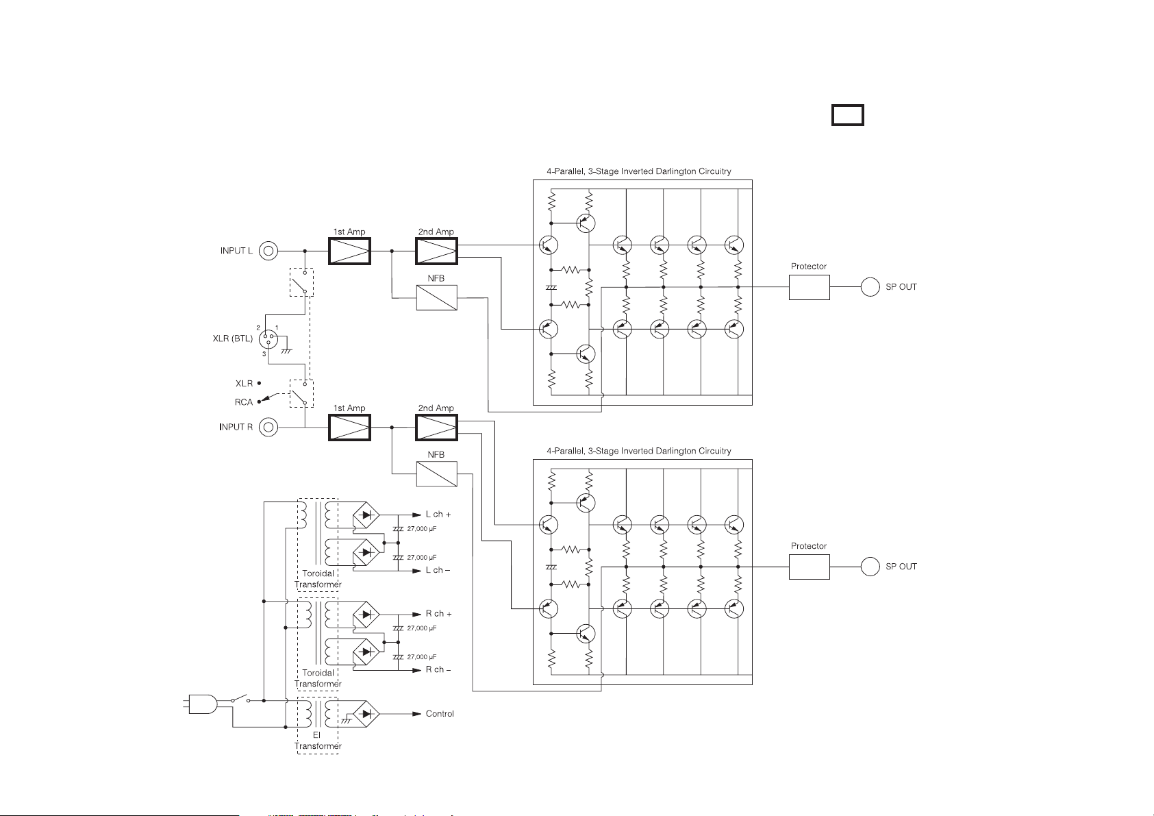
Block Diagram
DIDRC
(Dynamic Intermodulation Distortion Reduction Circuitry)
En
9
Page 10

Supplied Accessories
Make sure you have the following accessories:
Power cord
Power cord (1.8 m/5.9 ft) . . . . . . . . . . . . . . . . . . . . . . . . . . . . . . . . . . . . . . . . . . . . . . . . . (1)
(Plug type varies from country to country.)
Mono mini-plug cable
Mono mini-plug cable (1.8 m/5.9 ft) . . . . . . . . . . . . . . . . . . . . . . . . . . . . . . . . . . . . . . . . (1)
This is used to connect the 12V trigger jacks.
En
10
*
In catalogs and on packaging, the letter at the end of the product name indicates the color.
Specifications and operations are the same regardless of color.
Thank you for purchasing an Onkyo Power Amplifier. Please read this manual
thoroughly before making connections and plugging in the unit.
Following the instructions in this manual will enable you to obtain optimum
performance and listening enjoyment from your new Power Amplifier.
Please retain this manual for future reference.
Page 11

Contents
Introduction
Important Safety Instructions .................................................................................2
Precautions...............................................................................................................3
Amplifier Precautions ..............................................................................................5
Ventilation ............................................................................................................5
Installation location and space.............................................................................5
Power cord...........................................................................................................5
Speakers..............................................................................................................5
Care .....................................................................................................................6
Other....................................................................................................................6
Lightning storms ..................................................................................................6
Power...................................................................................................................6
Features ....................................................................................................................7
Technology ...............................................................................................................8
Block Diagram ..........................................................................................................9
Supplied Accessories ............................................................................................10
Getting to Know the Power Amplifier...................................................................12
Front Panel ........................................................................................................12
Rear Panel.........................................................................................................13
Installing the Power Amplifier...............................................................................14
Connections
Connections ...........................................................................................................15
Cable and Jacks ................................................................................................15
Connecting the Power Cord...............................................................................16
Connecting a Preamplifier .................................................................................17
Turning On & Basic Operations
Basic Operations....................................................................................................20
Turning On the Power Amplifier.........................................................................20
Turning Off the Power Amplifier.........................................................................20
Switching the Power Meter Range ....................................................................21
Setting Auto Standby (ASb)...............................................................................21
Others
Troubleshooting .....................................................................................................22
Specifications.........................................................................................................23
En
11
Page 12

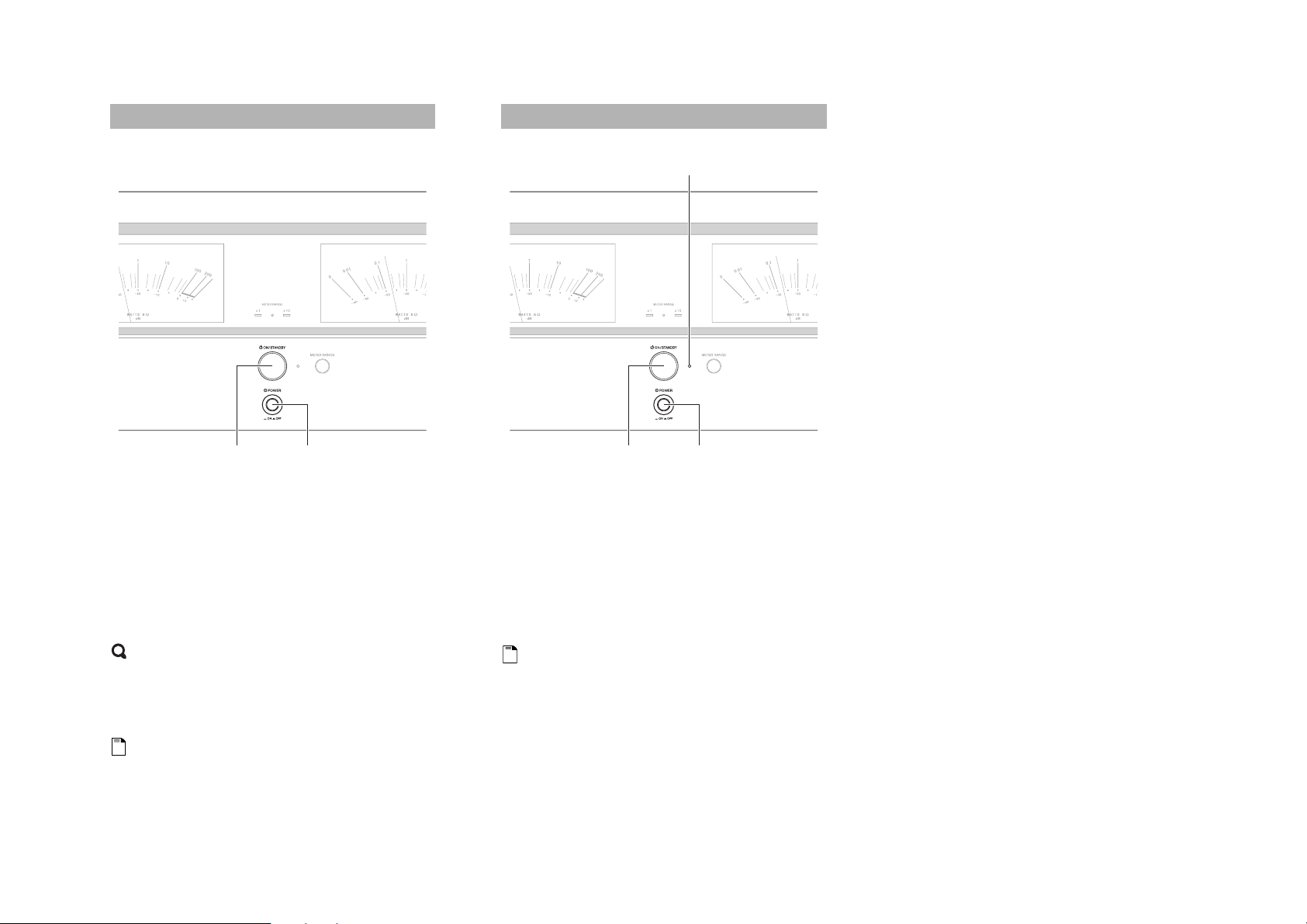
Getting to Know the Power Amplifier
Front Panel
a
En
12
b
The page numbers in parentheses show where you can find the main explanation for each item.
a Power meter (➔ 21)
The power meter shows the output power level.
The large power meters have been designed so that the
indicator needles move up to the peak level quickly
and then return more slowly. This makes it easier to
read transient power levels which last for only a
fraction of a second.
b METER RANGE LEDs (➔ 21)
x1 or x10 lights when the power meter range is x1 or
x10. The Off LED in the middle lights when the
power meter are turned off.
Before entering standby mode with the Asb function,
the Off LED flashes 30 seconds before the ASb
function starts running.
c ON/STANDBY button (➔ 20)
This button is used to set the power amplifier to On or
Standby.
d POWER switch (➔ 20)
This is the main power switch. When set to OFF, the
power amplifier is completely shutdown. It must be
set to ON to set the power amplifier to On or Standby.
e Standby LED (➔ 20)
Lights when the power amplifier is in Standby mode.
Flashes if the protection circuitry has been activated.
f METER RANGE button (➔ 21)
This button is used to switch the power meter range:
x1, x10 or off.
e fc d
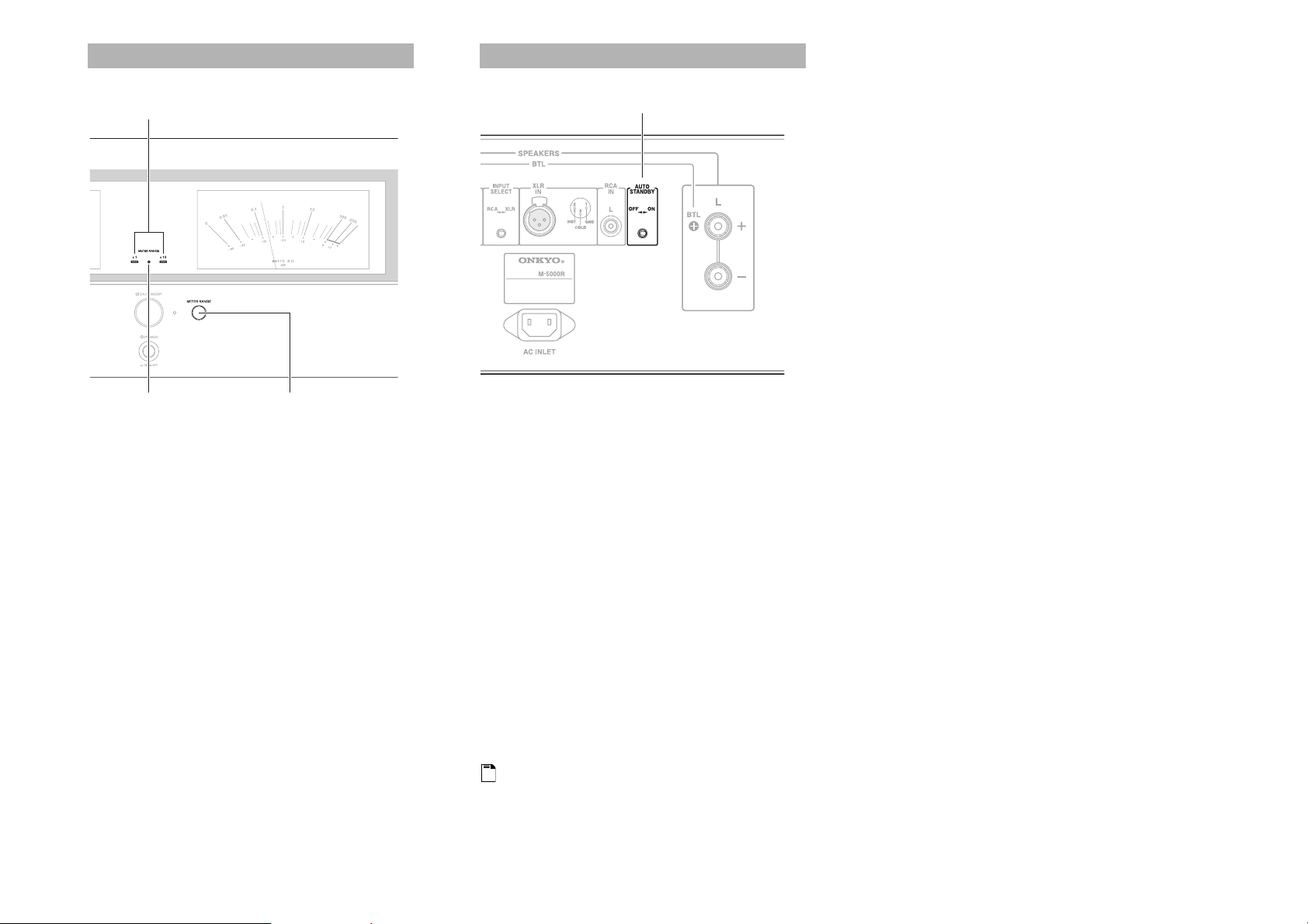
Page 13

Rear Panel
a SPEAKERS L/R terminals
b 12V TRIGGER IN/OUT jacks
Connects to the 12V trigger input and output jacks on
the other component to control the power amplifier.
This enables the amplifier to turn on or go into
standby state based on the standby status of the
connected component.
c INPUT SELECT switch
This switch is located between the XLR IN and RCA
IN. Use this switch to select the input type for its
channel. When setting the switch to the left side, the
RCA audio input is selected. When setting the switch
to the right side, the XLR input is selected.
a
b
f
d XLR IN jack
Connect preamplifier with XLR outputs for highquality sound.
Do not connect XLR and RCA at the same time. It
may damage the power amplifier.
e AUTO STANDBY switch
You can use the Auto Standby (ASb) function. If the
power amplifier receives no signal for 3 hours, it will
automatically enter standby mode. Once the ASb
function has been activated, the power amplifier will
not automatically turn on even if it receives the signal.
To turn on the power amplifier, press ON/STANDBY
manually. You can also disable the function by setting
this switch to OFF side.
f RCA IN L/R jacks
Connect preamplifier with single-ended outputs.
c
d
g
e
g AC INLET
The supplied power cord is connected here. The other
end of the power cord should be connected to a
suitable wall outlet.
See “Connections” for connection information
(➔ 15 to 19).
En
13
Page 14

Installing the Power Amplifier
v
30 cm (12")
Ensure proper ventilation.
En
14
10 cm (4")
10 cm (4")
10 cm (4")
Install the power amplifier on a sturdy rack or shelf. Position it so that its weight is evenly dispersed on its four legs. Do not install the power amplifier in a place with vibration or an unstable location.
The power amplifier is designed to have high conversion efficiency, however, its temperature will become much higher than other audio equipment. Therefore, make sure not to hamper heat
dissipation by ensuring proper ventilation.
Page 15
Connections
Connections
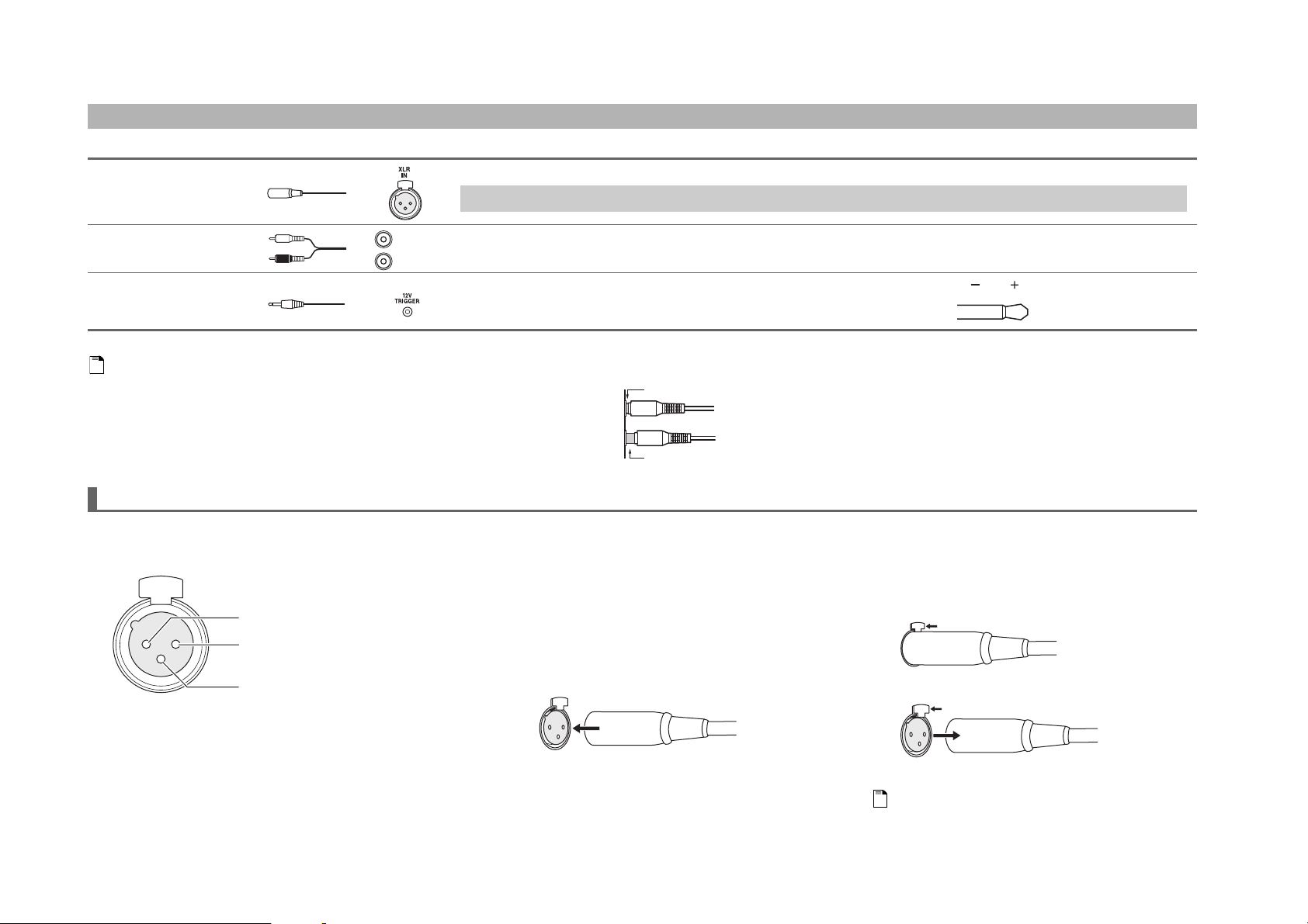
Cable and Jacks
XLR This cable carries analog audio. XLR cables are used for better noise immunity and longer cable runs.
Do not connect XLR and RCA at the same time. It may damage the power amplifier.
Analog audio (RCA) Analog audio connections (RCA) carry analog audio.
Mono mini-plug Use the supplied or commercially available mono mini-plug cable to connect to the 12V
L
White
R
Red
trigger jacks on the other device for linked operation.
The tip polarity of the connectors are as shown in the right.
Note
• Push plugs in all the way to make good connections (loose connections can cause noise or malfunctions).
• To prevent interference, keep audio cables away from power cords and speaker cables.
Right!
Wrong!
About XLR Input
Connect an AV controller or control amplifier with XLR
outputs for high-quality sound.
PUSH
2. HOT
2
1
3
Connector ground jack: Chassis grounded
1. GND
3. COLD
The pin assignments for this jack are given above. This pin
assignment conforms to the standard adopted by the Audio
Engineering Society. Refer to the instruction manual
supplied with the control amplifier and verify that its
output jack is compatible with the pin assignments for this
jack. The output jack of the AV controller PR-SC5508 is
compatible with the pin assignments for the jack of the
amplifier.
The power amplifier uses the European type XLR jack.
Phase is reversed when an XLR cable is connected to the
control amplifier that uses the USA type XLR jack. In this
case, reverse the polarity of the speaker connection.
Plugging the XLR cable
Match the pins and insert the jack until you hear a “click.”
Make sure that the jack is locked by lightly pulling the
connection cable.
Unplugging the XLR cable
Pull out the connection cable while holding down the
lever.
1
2
• When using this XLR connection between the control amplifier
and the amplifier, set the INPUT SELECT switch to the right
side (the XLR input side) to select XLR input.
• Do not connect anything to the RCA-type audio input jack.
12 volts positive tip
polarity
Push
Push
Note
En
15
Page 16
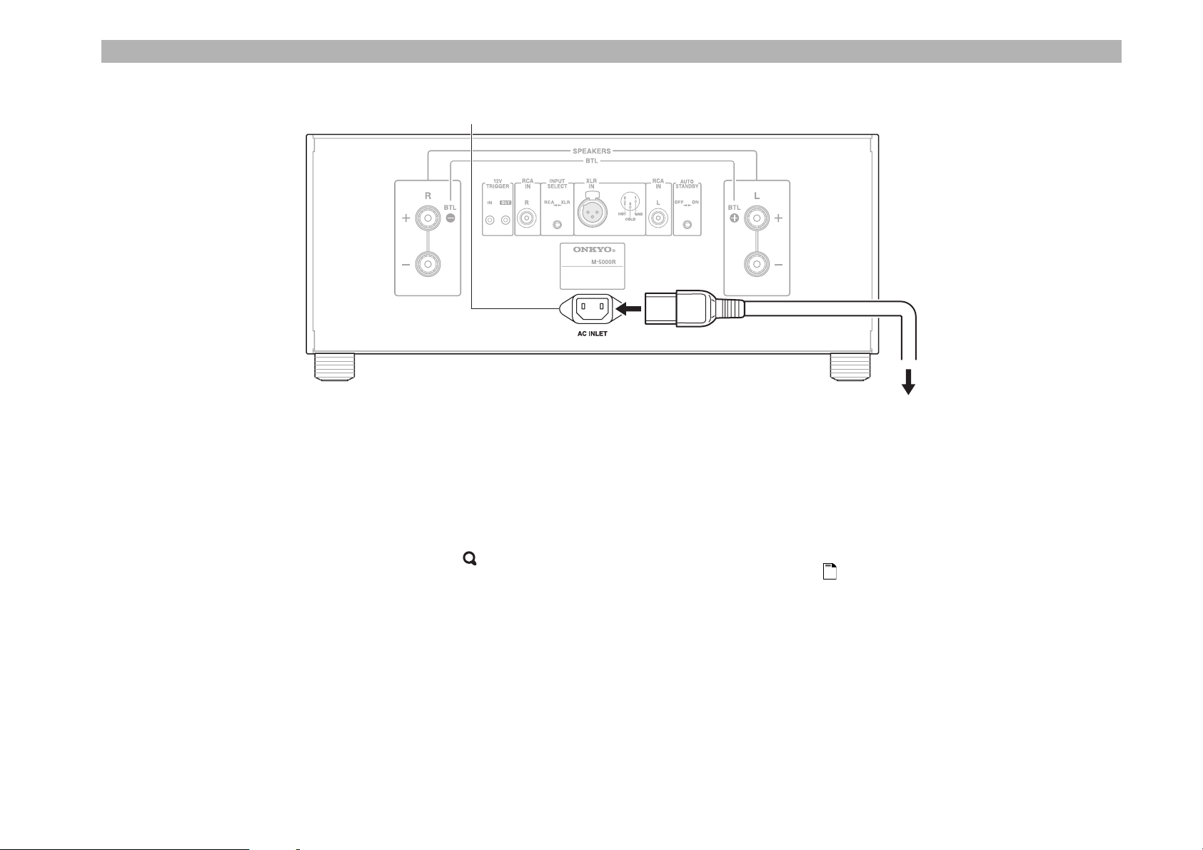
Connecting the Power Cord
AC INLET
Supplied power cord
To an AC wall outlet
(Plug type varies from
country to country.)
En
16
Make sure that the main power of the power
1
amplifier is turned off.
Connect all of your components.
2
Connect the supplied power cord to the amplifier’s
3
AC INLET.
Plug the power cord into an AC wall outlet.
4
Tip
• To reduce noise, do not tie the signal cable and power cable
together. Wire them so that they are away from each other.
Note
• Never disconnect the power cord from the power amplifier
while the other end is still plugged into a wall outlet. Doing so
may cause an electric shock. Always disconnect the power cord
from the wall outlet first, and then the power amplifier.
• Turning on the power amplifier may cause a momentary power
surge that might interfere with other electrical equipment on the
same circuit. If this is a problem, plug the power amplifier into a
different branch circuit.
• Do not use a power cord other than the one supplied with the
power amplifier. The supplied power cord is designed
exclusively for use with the power amplifier and should not be
used with any other equipment.
Page 17
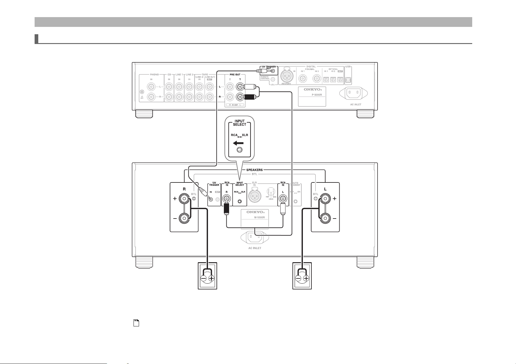
Connecting a Preamplifier
Stereo Connection
Preamplifier P-3000R
Power Amplifier M-5000R
Right speaker Left speaker
This is an example of the stereo connection using the preamplifier P-3000R.
Note
• Set the INPUT SELECT switch to RCA side.
En
17
Page 18
Bi-amping Connection
Preamplifier P-3000R
En
18
Power Amplifier
M-5000R
Tweeter (high)
Woofer (low)
Right speaker Left speaker
This is an example of the bi-amping connection using the preamplifier P-3000R.
Note
• Set the INPUT SELECT switch to RCA side.
Important:
• When making the bi-amping connections, be sure to remove the jumper bars that link the speakers’ tweeter (high) and woofer (low) jacks.
• Bi-amping can be used only with speakers that support bi-amping. Refer to your speaker manual.
Power Amplifier
M-5000R
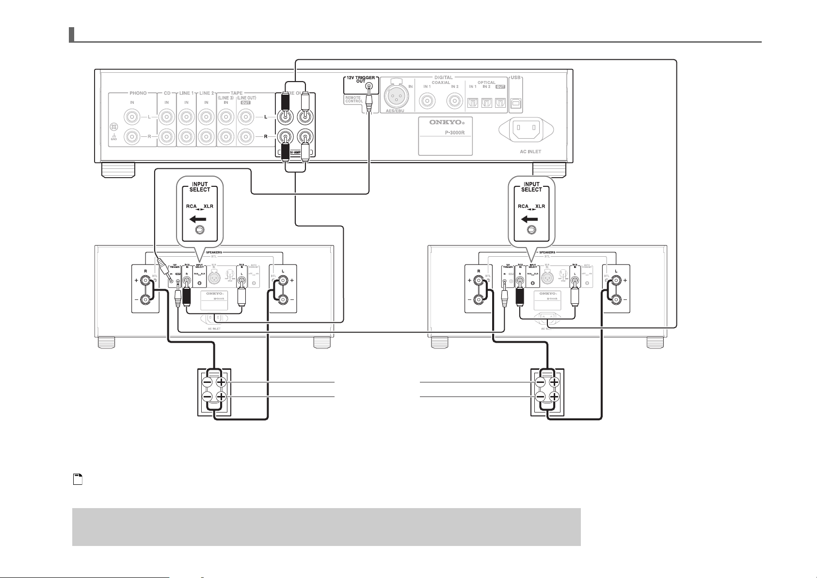
Page 19

Bridge Connection
Power Amplifier M-5000R Power Amplifier M-5000R
AV Controller PR-SC5508
Right Speaker
Left Speaker
This is an example of the bridge connection with the AV controller PR-SC5508.
Note
• When using the XLR inputs, do not connect anything to the RCA inputs. It may damage the power amplifier.
• Make sure that the XLR cable is not split. The split XLR cable may be the cause of noise.
• The power amplifier uses the European type XLR jack (pin 2 hot). If the AV controller/preamplifier with the USA type jack (pin 3 hot) is connected, the phase will be reversed. In this case, reverse the polarity of the speaker
connection.
•Set the INPUT SELECT switch to XLR side.
En
19
Page 20
Turning On & Basic Operations
Basic Operations
Turning On the Power Amplifier
POWERON/STANDBY
Set POWER to the ON position (^) on the front
1
panel.
Press ON/STANDBY to turn on the power
2
amplifier.
The power amplifier comes on, the display lights, and
the Standby LED goes off.
Turning Off the Power Amplifier
Standby LED
POWERON/STANDBY
Press ON/STANDBY to set the power amplifier to
1
Standby.
The power amplifier will enter Standby mode, and the
Standby LED lights.
To completely shut down the power amplifier, set
2
POWER to the OFF position (@).
En
20
Tip
• After a certain period of warming up, the temperature of the
power amplifier’s components and internal temperature are
stabilized, and the sound will soften.
Note
• The power amplifier remembers the state when power was
previously turned off, and returns to the state.
Note
• See “Setting Auto Standby (ASb)” for the auto standby function
(➔ 21).
Page 21
Switching the Power Meter Range
Setting Auto Standby (ASb)
x 1, x 10
Off LED
You can switch the power output of speaker terminals
between ×1 (default) and ×10 (10 times).
Press METER RANGE repeatedly to switch
1
METER RANGE in the following order:
×1 (default), ×10, Off
The x1, x10 LEDs and the Off LED will light
according to the set status of METER RANGE.
The number of watts indicated on the meters corresponds
to the actual output level when driving speakers rated at 8
ohms. When driving speakers rated at 4 ohms, the output
is actually twice that shown on the power meters.
METER RANGE
AUTO STANDBY
When AUTO STANDBY is turned ON side, the power
amplifier will automatically enter Standby mode if the
power amplifier receives no signal for 3 hours.
Set ON/OFF by switching the AUTO STANDBY
1
switch.
` ON:
ASb enabled.
` OFF:
ASb disabled.
Default setting: ON (European models), OFF (North
American models)
Once the ASb function has been activated, the power
amplifier will not automatically turn on even if it receives
the signal. To turn on the power amplifier, press
ON/STANDBY manually. You can also disable the
function by setting this switch to OFF side.
Note
• Before entering standby mode with the Asb function, the Off
LED flashes 30 seconds before the ASb function starts running.
En
21
Page 22

Others
Troubleshooting
Power
Can’t turn on the Power Amplifier.
• Make sure that the power cord is properly plugged into
the wall outlet (➔ 16).
• Unplug the power cord from the wall outlet, wait 5
seconds or more, then plug it in again.
The Power Amplifier turns off
unexpectedly.
• When the set ASb starts running, the power amplifier
will automatically go standby (➔ 21).
• If the power amplifier cannot start with the Standby LED
blinking, then it may be problem with the power
amplifier. If speaker cables touch the chassis, this may
cause the power amplifier to short out and make sure the
plus terminals of speaker cables do not touch the chassis
or the minus terminals.
Please try the method below:
–Set the POWER switch to OFF and disconnect all
speaker cables. Check that the top of the set (cooling
vent) is not blocked. When the power amplifier has
cooled down, reconnect all speaker cables and set the
POWER switch to ON. Then Press ON/STANDBY.
Audio
There’s no sound.
• Make sure the speakers are connected correctly (➔ 15).
• Check all connections and correct as necessary (➔ 15).
• When making XLR IN input, make sure that the INPUT
SELECT switch is switched to the XLR side.
• Make sure the correct input source is selected.
• Make sure the analog audio cable is connected correctly.
• Make sure that all audio connecting plugs are pushed in
all the way.
The sound quality is not good.
• Make sure the speaker cables are connected with the
correct polarity (➔ 15).
• Make sure all audio connecting plugs are pushed in all
the way (➔ 15).
• The sound quality can be affected by strong magnetic
fields, such as that from a TV. Try moving any such
devices away from the power amplifier.
• If you have any devices that emit high-intensity radio
waves near the power amplifier, such as a cellular phone
that’s being used to make a call, the power amplifier
may output noise.
• When making RCA IN input, make sure that the INPUT
SELECT switch is switched to the RCA side.
• Check the connection in case of bi-amping connection.
External Components
The 12V trigger does not work.
• Make sure the cables are connected to the jacks firmly.
The power amplifier contains a microcomputer for
signal processing and control functions. In very rare
situations, severe interference, noise from an external
source, or static electricity may cause it to lockup. In
the unlikely event that this should happen, unplug the
power cord, wait at least 5 seconds, and then plug it
again.
Before disconnecting the power cord from the wall
outlet, set the main power switch to OFF.
If during idling the cover is too hot to touch, then
ventilation needs to be improved.
En
22
Audio performance
• Audio performance will be at its best about 10 to 30
minutes after the power amplifier has been turned on and
had time to warm up.
• Using cable ties to bundle audio cables with speaker or
power cables may degrade the sound quality. So don’t
do it.
Page 23

Specifications
M-5000R
Amplifier Section
Rated Output Power
North American:
(Stereo) 80 watts minimum continuous power per
(BTL mono) 180 watts minimum continuous power per
European:
(Stereo)
(BTL mono)
channel, 8 ohm loads, 2 channels driven from
20 Hz to 20 kHz, with a maximum total
harmonic distortion of 0.05% (FTC)
100 watts minimum continuous power per
channel, 8 ohm loads, 2 channels driven at
1 kHz, with a maximum total harmonic
distortion of 1% (FTC)
150 watts minimum continuous power per
channel, 4 ohm loads, 2 channels driven from
20 Hz to 20 kHz, with a maximum total
harmonic distortion of 0.05% (FTC)
170 watts minimum continuous power per
channel, 4 ohm loads, 2 channels driven at 1 kHz,
with a maximum total harmonic distortion of
1% (FTC)
channel, 8 ohm loads, 1 channel driven from
20 Hz to 20 kHz, with a maximum total
harmonic distortion of 0.05% (FTC)
200 watts minimum continuous power per
channel, 8 ohm loads, 1 channel driven at 1 kHz,
with a maximum total harmonic distortion of
1% (FTC)
220 watts minimum continuous power per
channel, 6 ohm loads, 1 channel driven from
20 Hz to 20 kHz, with a maximum total
harmonic distortion of 0.05% (FTC)
250 watts minimum continuous power per
channel, 6 ohm loads, 1 channel driven at 1 kHz,
with a maximum total harmonic distortion of
1% (FTC)
2 ch × 80 W at 8 ohms, 20 Hz - 20 kHz, 0.05 %,
2 ch driven (IEC)
× 150 W at 4 ohms, 20 Hz - 20 kHz, 0.05 %,
2 ch
2 ch driven (IEC)
2 ch
× 100 W at 8 ohms, 1 kHz, 1 %, 2 ch driven
(IEC)
× 170 W at 4 ohms, 1 kHz, 1 %, 2 ch driven
2 ch
(IEC)
1ch × 180 W at 8 ohms, 20 Hz - 20 kHz, 0.05 %,
1 ch driven (IEC)
1ch
× 220 W at 6 ohms, 20 Hz - 20 kHz, 0.05 %,
1 ch driven (IEC)
1ch × 200 W at 8 ohms, 1 kHz, 1 %, 1 ch driven
(IEC)
× 250 W at 6 ohms, 1 kHz, 1 %, 1 ch driven
1ch
(IEC)
Dynamic Power
*
IEC60268-Short-term maximum output power
THD+N (Total Harmonic Distortion+Noise) 0.02 % (20 Hz - 20 kHz, half power)
Damping Factor 130 (1 kHz, 8 Ω)
Input Sensitivity and Impedance (Unbalance) 700 mV/10 kΩ (RCA)
Input Sensitivity and Impedance (Balance) 1.4 V/10 kΩ (BTL)
Frequency Response 10 Hz - 100 kHz/+0 dB, –1 dB 1 W/8 Ω
Signal to Noise Ratio 110 dB (RCA, IHF-A)
Speaker Impedance RCA Stereo: 4 Ω - 16 Ω
HICC 150 A
*
460 W (1 Ω)
320 W (2 Ω)
245 W (3 Ω)
196 W (4 Ω)
142 W (6 Ω)
110 W (8 Ω)
0.005 % (1 kHz, half power)
1 Hz - 250 kHz/+0 dB, –3 dB 1 W/8 Ω
XLR MONO: BTL 6 Ω - 16 Ω
General Section
Power Supply North American: AC 120 V, 60 Hz
Power Consumption North American: 8.4 A
Standby Power Consumption North American: 0.15 W
Dimensions (W × H × D) 435 W × 187.5 H × 432.5 D mm
Weight 23.5 kg (51.8 lbs.)
■ Audio Inputs
Analog Stereo Inputs RCA IN-L, RCA IN-R
Balance Inputs XLR IN
■ Audio Outputs
Speaker Outputs Lch, Rch
■ Others
12V Trigger In 1/Out 1
Specifications and features are subject to change without notice.
European: AC 230 V, 50 Hz
European: 280 W
European: 0.2 W
(17-1/8 W × 7-3/8 H × 17 D inches)
En
23
Page 24

2-1, Nisshin-cho, Neyagawa-shi, OSAKA 572-8540, JAPAN
Tel: 072-831-8023 Fax: 072-831-8163
http://www.onkyo.com/
18 Park Way, Upper Saddle River, N.J. 07458, U.S.A.
Tel: 800-229-1687, 201-785-2600 Fax: 201-785-2650
http://www.us.onkyo.com/
Liegnitzerstrasse 6, 82194 Groebenzell, GERMANY
Tel: +49-8142-4401-0 Fax: +49-8142-4401-555
http://www.eu.onkyo.com/
The Coach House 81A High Street, Marlow, Buckinghamshire, SL7 1AB, UK
Tel: +44-(0)1628-473-350 Fax: +44-(0)1628-401-700
Unit 1 & 12, 9/F, Ever Gain Plaza Tower 1, 88, Container Port Road, Kwai Chung,
N.T., Hong Kong. Tel: 852-2429-3118 Fax: 852-2428-9039
http://www.ch.onkyo.com/
1301, 555 Tower, No.555 West NanJin Road, Jin an, Shanghai,
China 200041, Tel: 86-21-52131366 Fax: 86-21-52130396
SN 29400545A
(C) Copyright 2011 ONKYO SOUND & VISION CORPORATION Japan. All rights reserved.
Y1102-2
* 2 9 4 0 0 5 4 5 A *
 Loading...