

Page 1

HT-S780En.book Page 1 Monday, February 28, 2005 2:13 PM
7.1ch Home Theater System
HT-S780
AV Receiver (HT-R530)
Front Speaker (SKF-530F)
Center Speaker (SKC-530C)
Contents
Introduction ..................................... 2
Connection .................................... 18
Turning On & First Time Setup..... 32
Surround Speaker (SKM-530S)
Surround Back Speaker (SKB-530)
Powered Subwoofer (SKW-530)
Instruction Manual
Thank you for purchasing an Onkyo 7.1ch Home
Theater System. Please read this manual thoroughly
before making connections and plugging in the unit.
Following the instructions in this manual will enable
you to obtain optimum performance and listening
enjoyment from your new 7.1ch Home Theater System.
Please retain this manual for future reference.
Basic Operation
Playing your AV components....... 34
Using the Tuner............................ 36
Enjoying the Listening Modes ..... 40
Advanced Operation..................... 44
Troubleshooting ............................ 55
E
n
Page 2
HT-S780En.book Page 2 Monday, February 28, 2005 2:13 PM
WARNING:
TO REDUCE THE RISK OF FIRE OR ELECTRIC
SHOCK, DO NOT EXPOSE THIS APPARATUS
TO RAIN OR MOISTURE.
CAUTION:
TO REDUCE THE RISK OF ELECTRIC SHOCK,
DO NOT REMOVE COVER (OR BACK). NO
USER-SERVICEABLE PARTS INSIDE. REFER
SERVICING TO QUALIFIED SERVICE
PERSONNEL.
Important Safety Instructions
1. Read these instructions.
2. Keep these instructions.
3. Heed all warnings.
4. Follow all instructions.
5. Do not use this apparatus near water.
6. Clean only with dry cloth.
7. Do not block any ventilation openings. Install in
accordance with the manufacturer’s instructions.
8. Do not install near any heat sources such as radiators, heat registers, stoves, or other apparatus
(including amplifiers) that produce heat.
9. Do not defeat the safety purpose of the polarized or
grounding-type plug. A polarized plug has two
blades with one wider than the other. A grounding
type plug has two blades and a third grounding
prong. The wide blade or the third prong are provided for your safety. If the provided plug does not
fit into your outlet, consult an electrician for
replacement of the obsolete outlet.
10. Protect the power cord from being walked on or
pinched particularly at plugs, convenience receptacles, and the point where they exit from the apparatus.
11. Only use attachments/accessories specified by the
manufacturer.
12.
Use only with the cart, stand,
tripod, bracket, or table specified by the manufacturer, or
sold with the apparatus.
When a cart is used, use caution when moving the cart/
apparatus combination to
avoid injury from tip-over.
13. Unplug this apparatus during lightning storms or
when unused for long periods of time.
14. Refer all servicing to qualified service personnel.
Servicing is required when the apparatus has been
damaged in any way, such as power-supply cord or
plug is damaged, liquid has been spilled or objects
have fallen into the apparatus, the apparatus has
been exposed to rain or moisture, does not operate
normally, or has been dropped.
PORTABLE CART WARNING
S3125A
WARNING
RISK OF ELECTRIC SHOCK
DO NOT OPEN
The lightning flash with arrowhead symbol, within an
equilateral triangle, is intended to alert the user to the
presence of uninsulated “dangerous voltage” within
the product’s enclosure that may be of sufficient
magnitude to constitute a risk of electric shock to
persons.
The exclamation point within an equilateral triangle is
intended to alert the user to the presence of important
operating and maintenance (servicing) instructions in
the literature accompanying the appliance.
AVIS
RISQUE DE CHOC ELECTRIQUE
NE PAS
OUVRIR
15. Damage Requiring Service
Unplug the apparatus from the wall outlet and refer
servicing to qualified service personnel under the
following conditions:
A. When the power-supply cord or plug is damaged,
B. If liquid has been spilled, or objects have fallen
into the apparatus,
C. If the apparatus has been exposed to rain or
water,
D. If the apparatus does not operate normally by
following the operating instructions. Adjust only
those controls that are covered by the operating
instructions as an improper adjustment of other
controls may result in damage and will often
require extensive work by a qualified technician
to restore the apparatus to its normal operation,
E. If the apparatus has been dropped or damaged in
any way, and
F. When the apparatus exhibits a distinct change in
performance this indicates a need for service.
16. Object and Liquid Entry
Never push objects of any kind into the apparatus
through openings as they may touch dangerous voltage points or short-out parts that could result in a
fire or electric shock.
The apparatus shall not be exposed to dripping or
splashing and no objects filled with liquids, such as
vases shall be placed on the apparatus.
Don’t put candles or other burning objects on top of
this unit.
17. Batteries
Always consider the environmental issues and follow local regulations when disposing of batteries.
18. If you install the apparatus in a built-in installation,
such as a bookcase or rack, ensure that there is adequate ventilation.
Leave 20 cm (8") of free space at the top and sides
and 10 cm (4") at the rear. The rear edge of the shelf
or board above the apparatus shall be set 10 cm (4")
away from the rear panel or wall, creating a flue-like
gap for warm air to escape.
2
Page 3

HT-S780En.book Page 3 Monday, February 28, 2005 2:13 PM
Precautions
1. Recording Copyright —Unless it’s for personal use
only, recording copyrighted material is illegal without the permission of the copyright holder.
2. AC Fuse —The AC fuse inside the unit is not user-
serviceable. If you cannot turn on the unit, contact
your Onkyo dealer.
3. Care —Occasionally you should dust the unit all
over with a soft cloth. For stubborn stains, use a soft
cloth dampened with a weak solution of mild detergent and water. Dry the unit immediately afterwards
with a clean cloth. Don’t use abrasive cloths, thinners, alcohol, or other chemical solvents, because
they may damage the finish or remove the panel lettering.
4. Power
WARNING
BEFORE PLUGGING IN THE UNIT FOR THE
FIRST TIME, READ THE FOLLOWING SECTION CAREFULLY.
AC outlet voltages vary from country to country.
Make sure that the voltage in your area meets the
voltage requirements printed on the unit’s rear panel
(e.g., AC 230 V, 50 Hz or AC 120 V, 60 Hz).
Some models have a voltage selector switch for
compatibility with power systems around the world.
Before you plug in such a model, make sure that the
voltage selector is set to the correct voltage for your
area.
Setting the [STANDBY/ON] switch to STANDBY
does not fully shutdown the unit. If you do not
intend to use the unit for an extended period,
remove the power cord from the AC outlet.
5. Never Touch this Unit with Wet Hands— Never
handle this unit or its power cord while your hands
are wet or damp. If water or any other liquid gets
inside this unit, have it checked by your Onkyo
dealer.
6. Handling Notes
• If you need to transport this unit, use the original
packaging to pack it how it was when you originally bought it.
• Do not leave rubber or plastic items on this unit
for a long time, because they may leave marks on
the case.
• This unit’s top and rear panels may get warm
after prolonged use. This is normal.
• If you do not use this unit for a long time, it may
not work properly the next time you turn it on, so
be sure to use it occasionally.
Memory Backup
The AV receiver uses a battery-less memory backup
system in order to retain radio presets and other settings
when it’s unplugged or in the case of a power failure.
Although no batteries are required, the AV receiver
must be plugged into an AC outlet in order to charge the
backup system. Once it has been charged, the AV
receiver will retain the settings for several weeks,
although this depends on the environment and will be
shorter in humid climates.
For U.S. models
FCC Information for User
CAUTION:
The user changes or modifications not expressly
approved by the party responsible for compliance could
void the user’s authority to operate the equipment.
NOTE:
This equipment has been tested and found to comply
with the limits for a Class B digital device, pursuant to
Part 15 of the FCC Rules. These limits are designed to
provide reasonable protection against harmful interference in a residential installation.
This equipment generates, uses and can radiate radio
frequency energy and, if not installed and used in accordance with the instructions, may cause harmful interference to radio communications. However, there is no
guarantee that interference will not occur in a particular
installation. If this equipment does cause harmful interference to radio or television reception, which can be
determined by turning the equipment off and on, the
user is encouraged to try to correct the interference by
one or more of the following measures:
• Reorient or relocate the receiving antenna.
• Increase the separation between the equipment and
receiver.
• Connect the equipment into an outlet on a circuit different from that to which the receiver is connected.
• Consult the dealer or an experienced radio/TV technician for help.
3
Page 4

HT-S780En.book Page 4 Monday, February 28, 2005 2:13 PM
1.
2.
3.
4.
5.
6.
7.
Precautions —Continued
For Canadian Models
NOTE:
COMPLIES WITH CANADIAN ICES-003.
For models having a power cord with a polarized plug:
CAUTION:
MATCH WIDE BLADE OF PLUG TO WIDE SLOT,
FULLY INSERT.
THIS CLASS B DIGITAL APPARATUS
TO PREVENT ELECTRIC SHOCK,
Modèle canadien
REMARQUE:
LA CLASSE B EST CONFORME À LA NORME
NMB-003 DU CANADA.
Sur les modèles dont la fiche est polarisée:
ATTENTION:
TRIQUES, INTRODUIRE LA LAME LA PLUS
LARGE DE LA FICHE DANS LA BORNE CORRESPONDANTE DE LA PRISE ET POUSSER
JUSQU’AU FOND.
CET APPAREIL NUMÉRIQUE DE
POUR ÉVITER LES CHOCS ÉLEC-
Speaker Precautions
Placement
• The speaker cabinets are made out of wood and are
therefore sensitive to extreme temperatures and
humidity, do not put them in locations subject to direct
sunlight or in humid places, such as near an air conditioner, humidifier, bathroom, or kitchen.
• Do not put water or other liquids close to the speakers.
If liquid is spilled over the speakers, the drive units
may be damaged.
• Speakers should only be placed on sturdy, flat surfaces
that are free from vibration. Putting them on uneven or
unstable surfaces, where they may fall and cause damage, will affect the sound quality.
• Subwoofer is designed to be used in the upright vertical position only. Do not use it in the horizontal or
tilted position.
• If the unit is used near a turntable or CD player, howling or slipping of sound may occur. To prevent this,
move the unit away from the turntable or CD player
otherwise lower the unit’s output level.
Using Close to a TV or Computer
TVs and computer monitors are magnetically sensitive
devices and as such are likely to suffer discoloration or
picture distortion when conventional speakers are placed
nearby. To prevent this, the SKF-530F and SKC-530C
feature internal magnetic shielding. In some situations,
however, discoloration may still be an issue, in which case
you should turn off your TV or monitor, wait 15 to 30
minutes, and then turn it back on again. This normally
activates the degaussing function, which neutralizes the
magnetic field, thereby removing any discoloration
effects. If discoloration problems persist, try moving the
speakers away from your TV or monitor. Note that discoloration can also be caused by a magnet or demagnetizing
tool that’s too close to your TV or monitor.
Input Signal Warning
The speakers can handle the specified input power when
used for normal music reproduction. If any of the following signals are fed to them, even if the input power is
within the specified rating, excessive current may flow in
the speaker coils, causing burning or wire breakage:
Interstation noise from an untuned FM radio.
Sound from fast-forwarding a cassette tape.
High-pitched sounds generated by an oscillator, electronic musical instrument, and so on.
Amplifier oscillation.
Special test tones from audio test CDs and so on.
Thumps and clicks caused by connecting or disconnecting audio cables (Always turn off your amplifier
before connecting or disconnecting cables.)
Microphone feedback.
4
Page 5
HT-S780En.book Page 5 Monday, February 28, 2005 2:13 PM
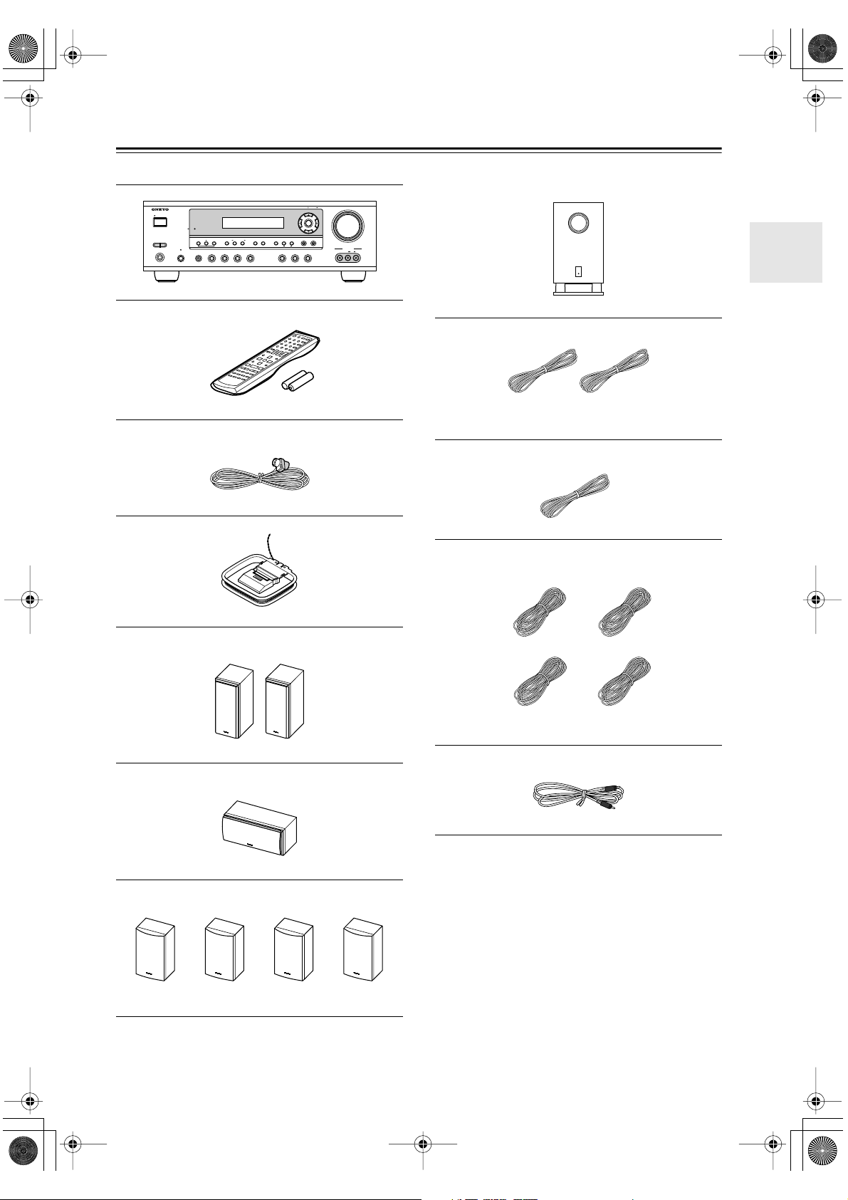
Supplied Accessories
Make sure you have the following accessories:
TUNING / PRESET
STANDBY/ON
STANDBY
A SPEAKERS B
PHONES
PURE AUDIO
+
TONE
STEREO
MULTl CH DVD VIDEO 1 VIDEO 2
VCR
AV receiver (HT-R530)
LISTENING MODE
DISPLAY
DIGITAL INPUT
VIDEO 3 TAPE TUNER CD
RT/PTY/TP MEMORY
TUNING MODE
CLEAR
MASTER VOLUME
ENTER
RETURN
SETUP
VIDEO
VIDEO 3 INPUT
AUDIO
LR
Subwoofer (SKW-530)
Remote controller & two batteries (AA/R6)
Indoor FM antenna
AM loop antenna
Front speakers (SKF-530F)
(Red) (White)
Speaker cable for front speakers 15 ft. (4.5 m)
(Green)
Speaker cable for center speaker 10 ft. (3 m)
(Blue) (Gray)
(Brown) (Tan)
Speaker cables for surround speakers 30 ft. (9 m)
Center speaker (SKC-530C)
Surround and Surround back speakers
(SKM-530S/SKB-530)
RCA cable for subwoofer connection 10 ft. (3 m)
* In catalogs and on packaging, the letter at the end of the
product name indicates the color. Specifications and operation are the same regardless of color.
5
Page 6

HT-S780En.book Page 6 Monday, February 28, 2005 2:13 PM
Features
Amp
• 7-channel amplifier
• 110 watts per channel at 8 Ω (FTC)
• WRAT (Wide Range Amplifier Technology)
• Optimum gain volume circuitry
• OptiResponse™ Equalizer (OR-EQ™)
*1
function
Processing
• Dolby
• DTS, DTS-ES Matrix/Discrete, DTS Neo:6, and DTS
• Cinema Filter function
• Linear PCM 192 kHz/24-bit D/A converters on all
• Pure Audio listening mode (not North American
•Powerful and highly accurate 32-bit DSP Processing
*2
Digital EX and Dolby Pro Logic IIx
96/24 processing
channels
model)
*3
Audio/Video
• Adjustable crossover (60, 80, 100, 120, 150 Hz)
• HDTV-capable component video (3 inputs, 1 output)
•3 S-Video inputs, 2 outputs
•4 assignable digital inputs (3 optical, 1 coaxial)
• Subwoofer pre out
• Color-coded multichannel input for use with Super
Audio CD and DVD-Audio
• A/B speaker drive
• Color-coded speaker terminal posts
FM/AM Tuner
• 30 FM/AM presets
• FM/AM auto tuning
Remote Controller
• Preprogrammed for use with other AV components
Speaker
• Color-coded speaker terminals and speaker cables
• Subwoofer Auto standby function
• Magnetic shielded front and center speakers
*1. OptiResponse and OR-EQ are trademarks of Onkyo Cor-
poration.
*2. Manufactured under license from Dolby Laboratories.
“Dolby”, “Pro Logic” and the double-D symbol are registered trademarks of Dolby Laboratories.
*3. “DTS,” “DTS 96/24,” “DTS-ES,” and “Neo:6” are trade-
marks of Digital Theater Systems, Inc.
6
Page 7
HT-S780En.book Page 7 Monday, February 28, 2005 2:13 PM
Table of Contents
Introduction
Important Safety Instructions .......................2
Precautions.....................................................3
Speaker Precautions......................................4
Supplied Accessories....................................5
Features ..........................................................6
Front & Rear Panels .......................................8
Remote Controller ........................................12
Before Using the AV receiver......................17
Connection
Connecting Speakers...................................18
Enjoying Home Theater............................18
Speaker Connection Precautions .............19
Connecting Speaker Set A .......................19
Connecting Speaker Set B
(sold separately).....................................19
Connecting Antenna ....................................20
Connecting the Indoor FM Antenna..........20
Connecting the AM Loop Antenna............20
Connecting an Outdoor FM Antenna........21
Connecting an Outdoor AM Antenna........21
Connecting Your Components ...................22
About AV Connections .............................22
Connecting Both Audio & Video ...............23
Which Connections Should I Use? ...........23
Connecting a TV or Projector ...................24
Connecting a DVD player .........................25
Connecting a VCR or DVD Recorder
for Playback............................................26
Connecting a VCR or DVD Recorder
for Recording..........................................27
Connecting a Camcorder,
Games Console, or Other Device ..........27
Connecting a Satellite, Cable,
Set-top box, or Other Video Source .......28
Connecting a CD Player or Turntable.......29
Connecting a Cassette, CDR, MiniDisc,
or DAT Recorder ....................................30
Connecting the Power Cord of Another
Component.............................................30
Connecting Onkyo Components ........31
Connecting the Power Cord .....................31
Turning On & First Time Setup
Turning On ....................................................32
Turning On the AV Receiver.....................32
First Time Setup ...........................................33
Assigning Digital Inputs to Input Sources .33
Changing the TAPE/MD/CDR Display......33
Basic Operation
Playing Your AV Components.................... 34
Basic AV Receiver Operation .................. 34
Using the Multichannel Input.................... 35
Displaying Source Information ................. 35
Using the Tuner ........................................... 36
Listening to the Radio .............................. 36
Tuning into Radio Stations....................... 36
Common Functions ..................................... 38
Setting the Display Brightness ................. 38
Adjusting the Bass & Treble..................... 38
Muting the AV Receiver ........................... 38
Using the OptiResponse Equalizer .......... 38
Using the Sleep Timer ............................. 39
Using Headphones .................................. 39
Adjusting Speaker Levels ........................ 39
Enjoying the Listening Modes
Using the Listening Modes ......................... 40
Selecting Listening Modes ....................... 40
Advanced Operation
Adjusting the Listening Modes................... 44
Using the Late Night Function
(Dolby Digital only) ................................ 44
Using the CinemaFILTER ........................ 44
Using the Audio Adjust Functions ............ 44
Advanced Setup........................................... 46
Advanced Speaker Settings..................... 46
Digital Input Signal Formats..................... 50
Recording ..................................................... 51
Recording the Input Source ..................... 51
Recording from Different AV Sources...... 51
Controlling Other Components .................. 52
Entering Remote Control Codes .............. 52
Remote Control Codes for Onkyo
Components Connected via ............ 53
Resetting the REMOTE MODE Buttons .. 53
Resetting the Remote Controller.............. 53
Controlling a TV ....................................... 54
Controlling a VCR .................................... 54
Controlling a Satellite/ Cable Receiver .... 54
Troubleshooting........................................... 55
Specification ................................................ 58
7
Page 8
HT-S780En.book Page 8 Monday, February 28, 2005 2:13 PM
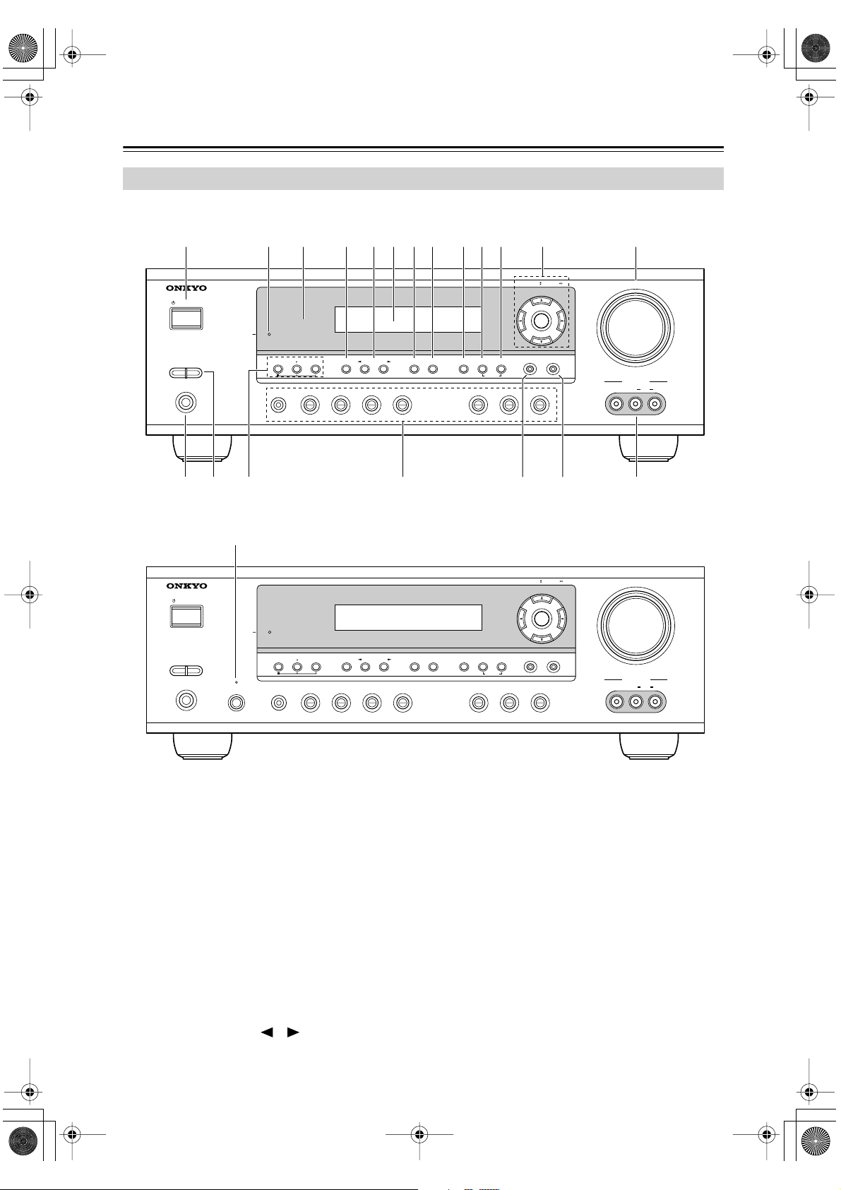
Front & Rear Panels
Front Panel
North American Model
1
STANDBY/ON
A SPEAKERS B
PHONES
Other Models
STANDBY/ON
U
2
3 4 5 7 8 9 J K L M6
STANDBY
TONE
MULTl CH DVD VIDEO 1 VIDEO 2
STANDBY
TUNING / PRESET
ENTER
RETURN
+
STEREO
VCR
LISTENING MODE
DISPLAY
DIGITAL INPUT
DIMMER MEMORY
VIDEO 3 TAPE TUNER CD
TUNING MODE
CLEAR
SETUP
MASTER VOLUME
VIDEO
VIDEO 3 INPUT
LR
AUDIO
TQN O P R S
TUNING / PRESET
ENTER
MASTER VOLUME
A SPEAKERS B
PHONES
PURE AUDIO
MULTl CH DVD VIDEO 1 VIDEO 2
+
TONE
STEREO
VCR
LISTENING MODE
For detailed information, see the pages in parentheses.
STANDBY/ON button (32)
A
This button is used to set the AV receiver to On or
Standby.
STANDBY indicator (32)
B
This indicator lights up when the AV receiver is in
Standby mode, and it flashes while a signal is being
received from the remote controller.
C
Remote-control sensor (17)
This sensor receives control signals from the remote
controller.
D
STEREO button (40)
This button is used to select the Stereo listening
mode.
E
LISTENING MODE [ ]/[ ] buttons (40)
These buttons are used to select the listening modes.
DISPLAY
DIGITAL INPUT
VIDEO 3 TAPE TUNER CD
F
MEMORY
DIMMER
Display
TUNING MODE
CLEAR
RETURN
See “Display” on page 9.
G
DISPLAY button (35)
This button is used to display various information
about the currently selected input source.
H
DIGITAL INPUT button (33)
This button is used to assign the digital inputs and to
specify the format of digital input signals.
I
DIMMER button (38)
This button is used to adjust the display brightness.
J
MEMORY button (37)
This button is used when storing or deleting radio
presets.
SETUP
VIDEO
VIDEO 3 INPUT
LR
AUDIO
8
Page 9
HT-S780En.book Page 9 Monday, February 28, 2005 2:13 PM
Front & Rear Panels —Continued
TUNING MODE button (36)
K
This button is used to select the Auto or Manual tuning mode.
L
Arrow/TUNING/PRESET & ENTER buttons
When the AM or FM input source is selected, the
TUNING [ ] [ ] buttons are used to tune the
tuner, and the PRESET [ ] [ ] buttons are used
to select radio presets (see page 36). When the setup
menus are used, they work as arrow buttons and are
used to select and set items. The ENTER button is
also used with the setup menus.
MASTER VOLUME control (34)
M
This control is used to adjust the volume of the AV
receiver to MIN, 1 through 79, or MAX
N
PHONES jack (39)
This 1/4-inch phone jack is for connecting a standard pair of stereo headphones for private listening.
O
SPEAKER A & B buttons (34)
These buttons are used to turn speaker sets A and B
on or off.
P
TONE, [–] & [+] buttons (38)
These buttons are used to adjust the bass and treble.
Input selector buttons (34)
Q
These buttons are used to select from the following
input sources: MULTI CH, DVD, VIDEO 1,
VIDEO 2, VIDEO 3, TAPE, TUNER, or CD.
The [MULTI CH] button selects the DVD analog
multichannel input.
R
RETURN button
This button is used to return to the previously displayed setup menu.
S
SETUP button
This button is used to access various settings.
T
VIDEO 3 INPUT (27, 51)
This input can be used to connect a camcorder,
games console, and so on. There are jacks for composite video and analog audio.
U
PURE AUDIO button & indicator (40)
The North American model doesn’t have this button
and indicator.
This button is used to select the Pure Audio listening mode. The indicator lights up when that mode is
selected.
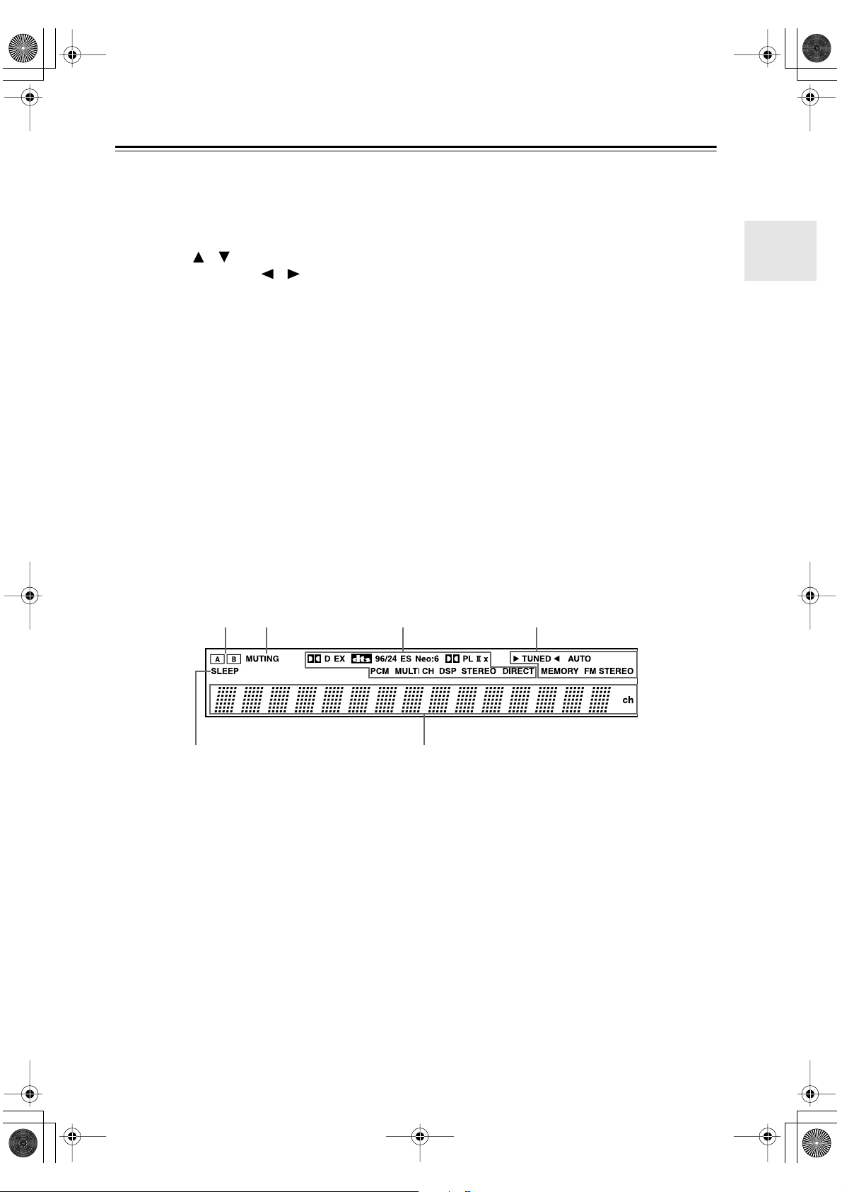
Display
2134
5
For detailed information, see the pages in parentheses.
A & B speaker indicators (34)
1
Indicator A lights up when speaker set A is on. Indicator B lights up when speaker set B is on.
2
MUTING indicator (38)
This indicator flashes when the AV receiver is
muted.
3
Source/listening mode indicators (42)
These indicators show the currently selected listening mode and digital audio format.
4
Tuning indicators (36)
TUNED (36): This indicator lights up when the AV
receiver is tuned to a radio station.
AUTO (36): This indicator lights up when Auto
Tuning is selected and disappears when Manual
Tuning is selected.
6
MEMORY (37): This indicator lights up when pre-
setting radio stations.
FM STEREO (36): This indicator lights up when
the AV receiver is tuned to a stereo FM station.
5
SLEEP indicator (39)
This indicator lights up when the Sleep function has
been set.
6
Message area
This area of the display shows various information
about the currently selected source.
9
Page 10
HT-S780En.book Page 10 Monday, February 28, 2005 2:13 PM
Front & Rear Panels —Continued
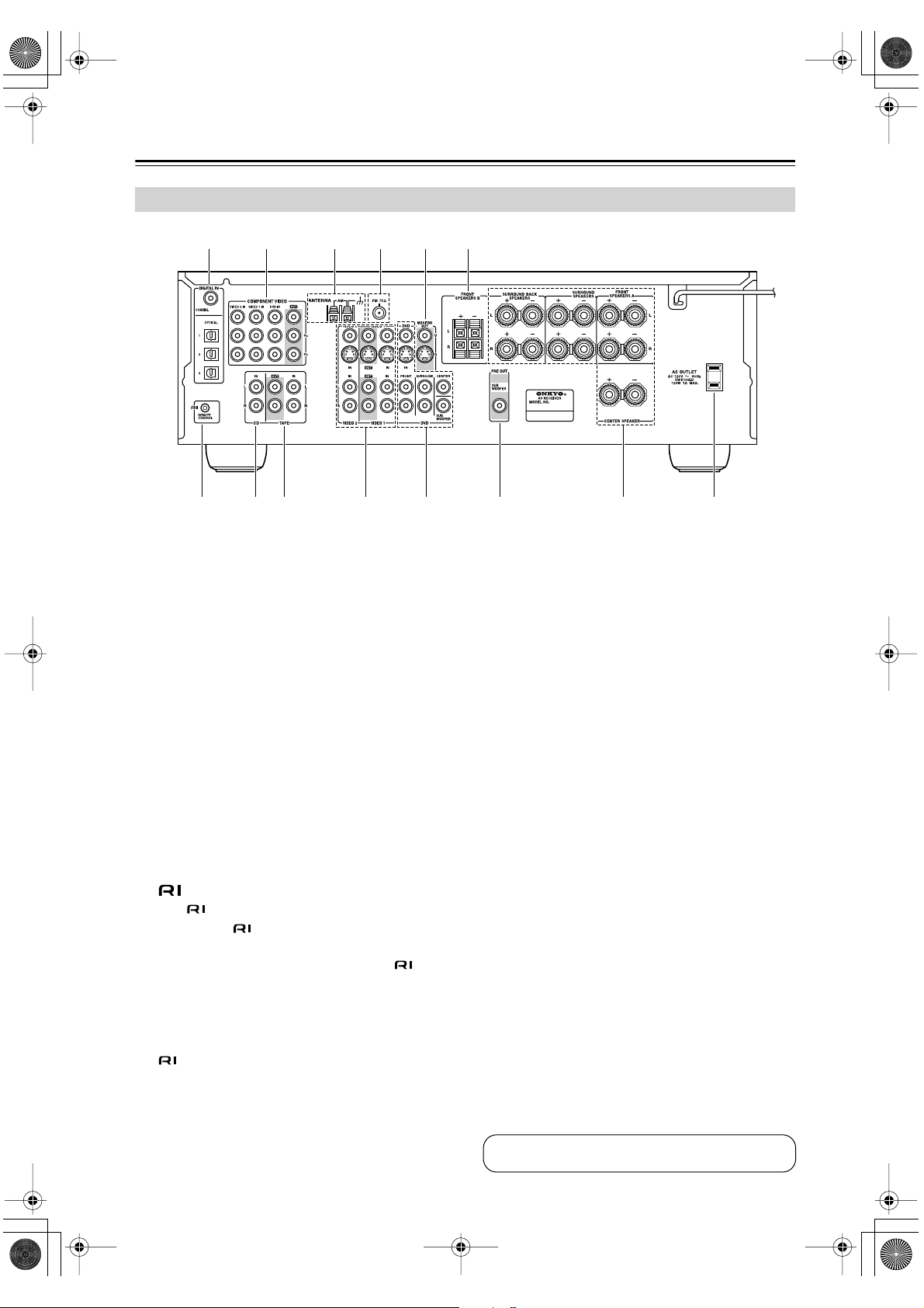
Rear Panel
1 B 3 4 65
7 8 9 J K L N
A
DIGITAL IN OPTICAL 1, 2, 3 & COAXIAL
These optical and coaxial jacks can be used to connect a CD or DVD player and other components
with digital audio outputs.
B
COMPONENT VIDEO
A DVD player, TV, or other component that supports component video can be connected here.
C
AM ANTENNA
These push terminals are for connecting an AM
antenna.
D
FM ANTENNA
This jack is for connecting an FM antenna.
E
MONITOR OUT
The S-Video or composite video output should be
connected to a video input on your TV or projector.
F
FRONT SPEAKERS B
These push terminals are for connecting speaker
set B.
G
This (Remote Interactive) jack can be connected to the jack on another Onkyo compo-
nent. The AV receiver’s remote controller can then
be used to control that component. To use , you
must make an analog audio connection (RCA)
between the AV receiver and the other component,
even if they are connected digitally.
Note:
can only be used with Onkyo components.
H
CD IN
These analog inputs can be used to connect a CD
player with analog outputs.
M
I
TAPE IN/OUT
These analog inputs and outputs can be used to connect a cassette recorder, MiniDisc recorder, or other
recorder with analog inputs and outputs.
J
VIDEO 1 IN/OUT & VIDEO 2 IN
The VIDEO 1 S-Video, composite video, and audio
inputs and outputs can be used to connect a VCR.
The VIDEO 2 S-Video, composite video, and audio
inputs can be used to connect another video source
(e.g., cable TV, satellite TV, or a set-top box).
K
DVD IN/MULTI CH INPUT
The FRONT, SURROUND, CENTER, and SUBWOOFER jacks can be used to connect a component with an analog multichannel audio output, such
as a DVD player with a 5.1-channel analog output.
The S-Video or composite video input should be
connected to a video output on the DVD player.
L
SUBWOOFER PRE OUT
A powered subwoofer can be connected here.
M
FRONT SPEAKERS A, SURROUND
SPEAKERS, CENTER SPEAKER &
SURROUND BACK SPEAKERS
These terminal posts are for connecting speaker
set A.
AC OUTLET
N
This switched AC outlet can be used to supply
power to another component. The connector type
depends on the country in which you purchased
your AV receiver.
10
See pages 18–31 for connection information.
Page 11
HT-S780En.book Page 11 Monday, February 28, 2005 2:13 PM
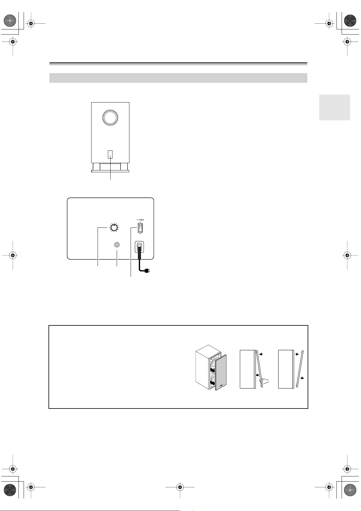
Front & Rear Panels —Continued
Subwoofer (SKW-530)
For detailed information, see the pages in parentheses.
■ Front
1
■ Rear
MIN
MAX
OUTPUT
LEVEL
A
STANDBY/ON indicator
Red: Subwoofer in standby mode
Green: Subwoofer on
With the Auto Standby function, the SKW-530
automatically turns on when an input signal is
detected in Standby mode. When there’s no input
signal for a while, the SKW-530 automatically
enters Standby mode.
B
OUTPUT LEVEL control (34)
This control is used to adjust the volume of the subwoofer.
C
LINE INPUT (19)
This RCA input should be connected to the subwoofer pre out on the AV receiver with supplied
RCA cable.
D
POWER switch (Not North American model)
(32)
Press this switch to the ON position to turn on the
power. Press it to the OFF position to turn off the
power.
LINE INPUT
2
(Not North American model)
3
4
To AC outlet
■ Attaching and detaching the speaker grilles
Front and Center speakers have detachable grilles. Use the
following method to attach or detach the grilles.
1. While holding the bottom edge of the speaker grille with
your both hands, pull it gently toward you to remove the
bottom of the grille.
2. In the same way, gently pull the upper edge of the
speaker grille toward you to remove it from the main
unit.
3. To replace the grill, push the projections at the corners
into the grille plug holes on the speaker cabinet.
Note:
The Auto Standby function turns the subwoofer on when
the input signal exceeds a certain level. If the Auto
Standby function does not work reliably, try slightly
increasing or decreasing the subwoofer output level on
the AV receiver (page 47).
ReplacementRemoval
11
Page 12
HT-S780En.book Page 12 Monday, February 28, 2005 2:13 PM
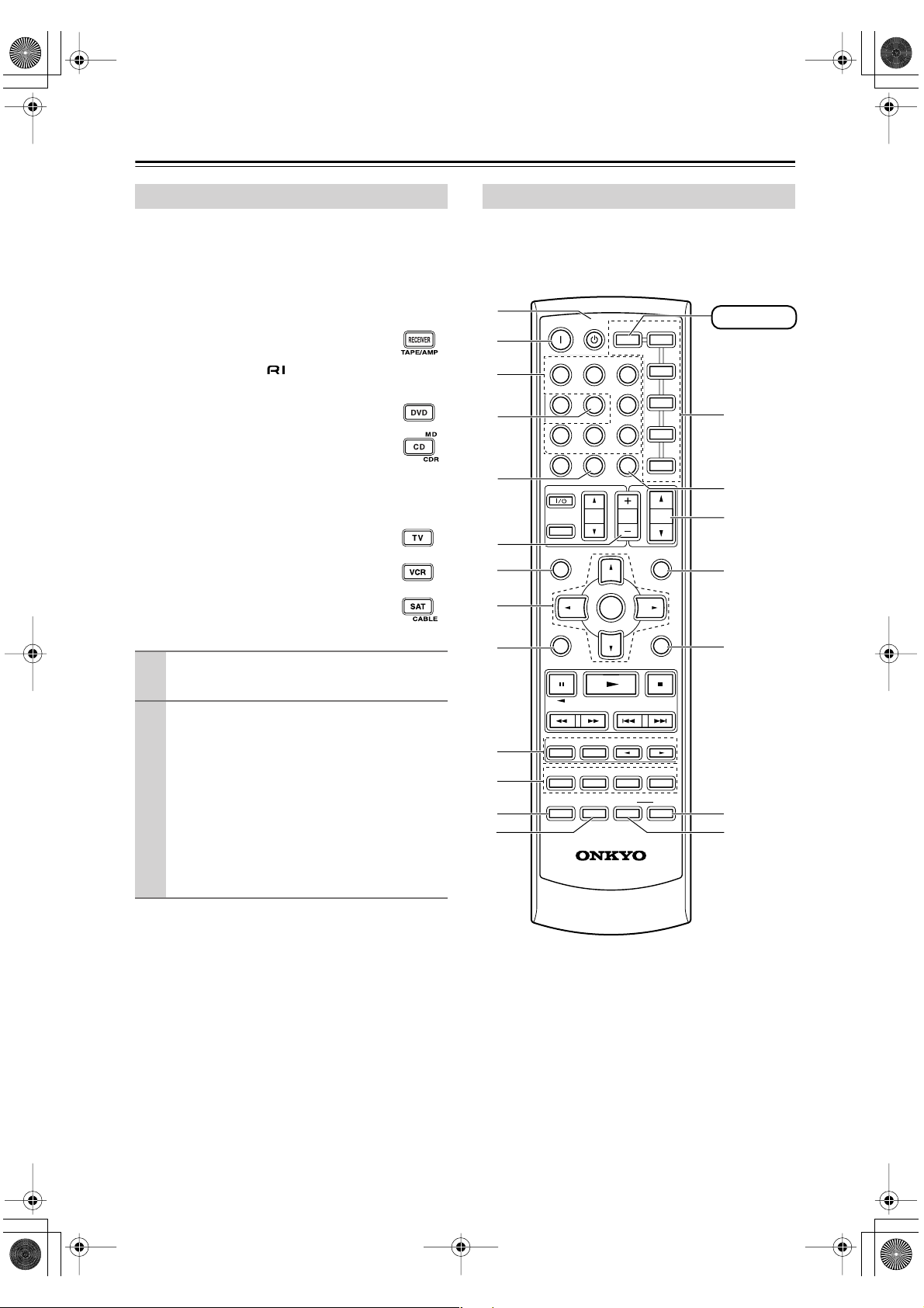
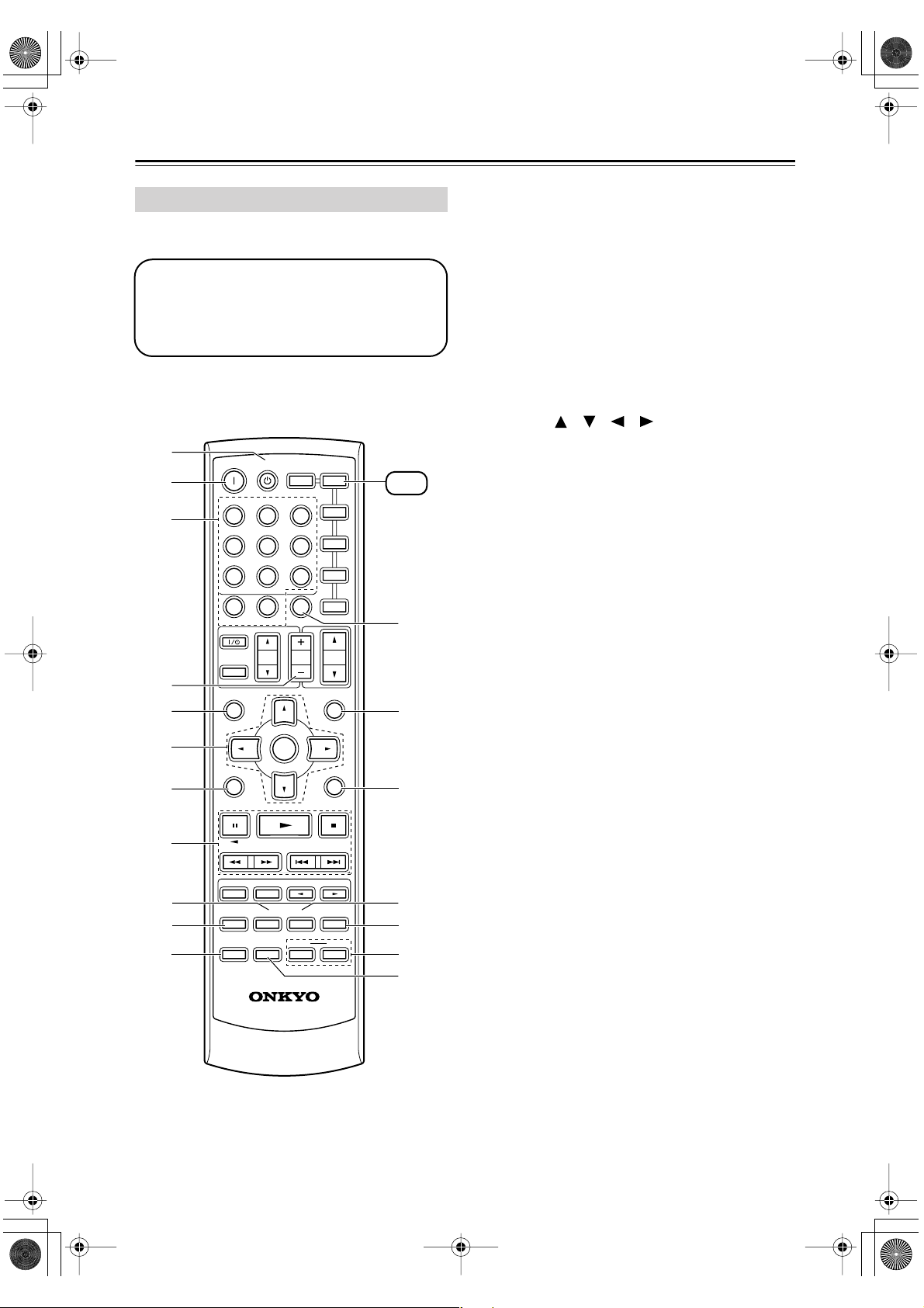
Remote Controller
■
■
■
How to Use the Remote Controller
Including the AV receiver, the remote controller can be
used to control up to seven different components. The
remote controller has a specific operating mode for use
with each type of component. Modes are selected by
using the six REMOTE MODE buttons.
RECEIVER/TAPE Mode
In RECEIVER/TAPE mode, you can control
the AV receiver and an Onkyo cassette
recorder connected via .
DVD & CD/MD/CDR Modes
With these modes, you can control a DVD
player and CD/MD/CDR player/recorder.
By entering the appropriate remote control
code, you can control Onkyo components or
components made by other manufacturers
(see page 52).
TV, VCR & SAT/CABLE Modes
With these modes, you can control a TV,
VCR, and satellite/cable receiver. You must
enter the appropriate remote control code
first (see page 52).
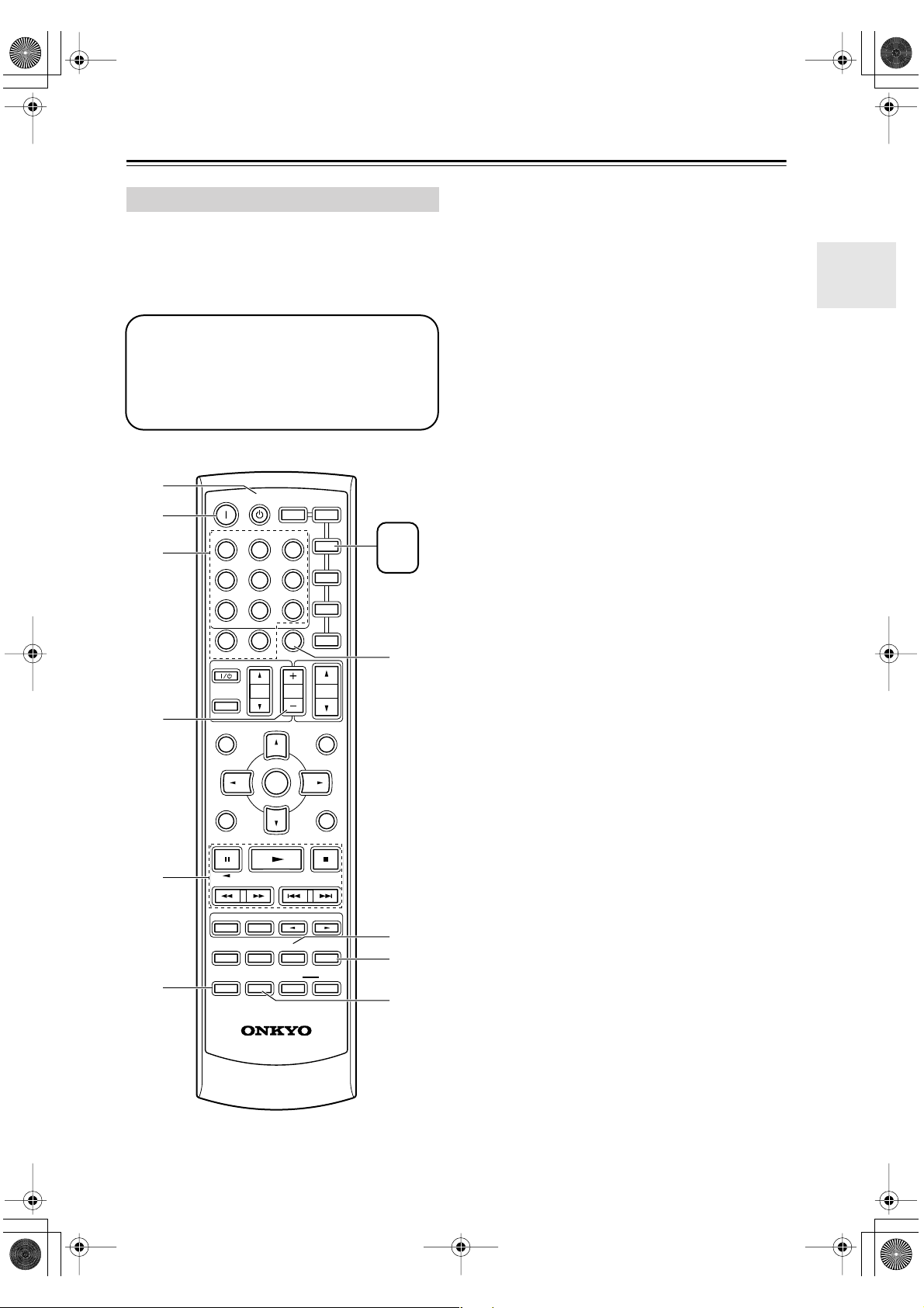
RECEIVER Mode
RECEIVER mode is used to control the AV receiver.
To set the remote controller to RECEIVER mode,
press the [RECEIVER] REMOTE MODE button.
A
B
C
D
E
F
G
H
ON STANDBY
INPUT SELECTOR
123
V1V2V
456
789
+
10
10 11 12
--/---
TV
INPUT
GUIDE
TOP MENU
SP A / B
RECEIVER
TAPE/AMP
MULTI CH
0
DIMMER SLEEP
VOL
ENTER
REMOTE MODE
DVD
C DTAPE TUNER
CLR
CH
DISC
DVD
M
C D
CDR
3
TV
VCR
SAT
CABLE
VOL
PREVIOUS
MENU
MUTING
D
RECEIVER
N
O
P
Q
Use the REMOTE MODE buttons to select
1
a mode.
Use the buttons supported by that mode
2
to control the component.
RECEIVER mode: see page 12
DVD mode: see page 14
CD/MD/CDR mode: see page 15
TAPE mode: see page 16
TV mode: see page 54
see page 16 for TV
control buttons
VCR, SAT/CABLE mode: see page 54
Note:
Some of the remote controller operations described in
this manual may not work as expected with other components.
I
J
K
L
M
SETUPRETURN
LISTENING MODE
SURROUND
STEREO
SUBTITLE
AUDIO REPEAT
TEST TONE
DISPLAY
CH SEL
PLAY MODE
OR-EQ
RC
RANDOM
-
608M
LEVEL
L NIGHT
-
LEVEL
DVDHDD
CINE FLTR
R
+
S
T
12
Page 13

HT-S780En.book Page 13 Monday, February 28, 2005 2:13 PM
Remote Controller —Continued
For detailed information, see the pages in parentheses.
A
STANDBY button (32)
This button is used to set the AV receiver to
Standby.
ON button (32)
B
This button is used to turn on the AV receiver.
C
INPUT SELECTOR buttons (34)
These buttons are used to select the input sources.
MULTI CH button (35)
D
This button is used to select the multichannel DVD
input.
DIMMER button (38)
E
This button is used to adjust the display brightness.
CH +/– button (37)
F
This button is used to select radio presets.
G
SP A/B button (34)
This button is used to turn speaker sets A and B on
or off.
H
Arrow [ ]/[ ]/[ ]/[ ] & ENTER buttons
These buttons are used to select and adjust settings.
I
RETURN button
This button is used to return to the previous display
when changing settings.
J
LISTENING MODE buttons (40)
These buttons can be used to select listening modes
regardless of the currently selected remote controller mode.
STEREO button
This button selects the Stereo listening mode.
SURROUND button
This button selects the Dolby and DTS listening
modes.
[ ]/[ ] buttons
These buttons can be used to select any of the available listening modes.
TEST TONE, CH SEL, LEVEL- & LEVEL+
K
buttons (32)
These buttons are used to adjust the level of each
speaker.
L
DISPLAY button (35, 52)
This button is used to display various information
about the currently selected input source.
M
OR-EQ button (38)
This button is used to turn on the OptiResponse
equalizer, which optimizes performance when the
HT-R530 is used with the speakers included in this
Speaker Package. When the OptiResponse equalizer
is on, you can enjoy a powerful sound with movies
or music with small volume.
REMOTE MODE buttons (12)
N
These buttons are used to select the remote controller modes. When you press a button on the remote
controller, the REMOTE MODE button for the currently selected mode lights up.
O
SLEEP button (39)
This button is used to set the Sleep function.
P
VOL [ ]/[ ] button (34)
This button can be used to adjust the volume of the
AV receiver regardless of the currently selected
remote controller mode.
MUTING button (38)
Q
This button is used to mute the AV receiver.
R
SETUP button
This button is used to access various settings.
S
CINE FLTR button (44)
This button is used to set the CinemaFILTER function.
T
L NIGHT button (44)
This button is used to set the Late Night function.
13
Page 14
HT-S780En.book Page 14 Monday, February 28, 2005 2:13 PM
Remote Controller —Continued
DVD Mode
To set the remote controller to DVD mode, press the
[DVD] REMOTE MODE button.
Before selecting DVD mode and starting playback, you should press the [RECEIVER] mode
button followed by the [DVD] INPUT SELECTOR button to select the DVD player as the
input source.
A
B
C
D
E
F
G
H
I
J
K
ON STANDBY
INPUT SELECTOR
123
V
1
456
789
+
10
10 11 12
--/---
TV
INPUT
GUIDE
TOP MENU
SP A / B
STEREO
AUDIO REPEAT
TEST TONE
DISPLAY
TAPE/AMP
V2V
MULTI CH
0
DIMMER SLEEP
VOL
ENTER
LISTENING MODE
SURROUND
SUBTITLE
RANDOM
CH SEL
PLAY MODE
OR-EQ
-
RC
608M
REMOTE MODE
RECEIVER
3
DVD
C DTAPE TUNER
CLR
CH
DISC
PREVIOUS
-
LEVEL
L NIGHT
DVD
C D
TV
VCR
SAT
CABLE
VOL
MENU
MUTING
SETUPRETURN
LEVEL
DVDHDD
CINE FLTR
M
D
CDR
+
DVD
L
M
N
O
P
Q
R
A
STANDBY button
This button sets the DVD player to Standby.
B
ON button
This button is used to turn on the DVD player.
Number buttons
C
These buttons are used to enter title, chapter, and
track numbers and to enter times for locating specific points in time.
D
DISC +/– button
This button selects discs on a DVD changer.
TOP MENU button
E
This button is used to select a DVD’s top menu.
Arrow [ ]/[ ]/[ ]/[ ] & ENTER buttons
F
These buttons are used to navigate DVD menus and
the DVD player’s onscreen setup menus.
RETURN button
G
This button is used to exit the DVD player’s
onscreen setup menu and to restart menu playback.
Playback buttons
H
From left to right: Pause, Play, Stop, Fast Reverse,
Fast Forward, Previous, and Next.
SUBTITLE button
I
This button is used to select subtitles.
AUDIO button
J
This button selects foreign language soundtracks
and audio formats (e.g., Dolby Digital or DTS).
DISPLAY button
K
This button is used to display information about the
current disc, title, chapter, or track on the DVD
player’s display, including the elapsed time, remaining time, total time, and so on.
L
CLR button
This button is used to cancel functions and to clear
entered numbers.
M
MENU button
This button is used to display a DVD’s menu.
SETUP button
N
This button is used to access the DVD player’s
onscreen setup menus.
RANDOM button
O
This button is used with the random playback function.
REPEAT button
P
This button is used to set the repeat playback functions.
HDD & DVD buttons
Q
These buttons are used to select hard disk (HDD) or
DVD playback on a DVD recorder with a built-in
hard disk drive.
R
PLAY MODE button
This button is used to select play modes on a component with selectable play modes.
14
Page 15
HT-S780En.book Page 15 Monday, February 28, 2005 2:13 PM
Remote Controller —Continued
CD/MD/CDR Mode
By default, the AV receiver is configured to control an
Onkyo CD player.
To set the remote controller to CD/MD/CDR mode,
press the [CD] REMOTE MODE button.
Before selecting CD/MD/CDR mode and starting playback, you should press the
[RECEIVER] mode button followed by the [CD]
or [TAPE] INPUT SELECTOR button to select
the CD player, MiniDisc, or CD recorder as the
input source.
A
B
C
D
ON STANDBY
INPUT SELECTOR
123
V1V
456
789
+
10
10 11 12
--/---
TV
INPUT
GUIDE
TOP MENU
SP A / B
RECEIVER
TAPE/AMP
2
MULTI CH
0
DIMMER SLEEP
VOL
ENTER
REMOTE MODE
V
DVD
C DTAPE TUNER
CLR
CH
DISC
DVD
D
M
C D
CDR
3
TV
VCR
SAT
CABLE
VOL
PREVIOUS
MENU
MUTING
MD
CD
CDR
G
A
STANDBY button
This button sets the CD player or MD/CD recorder
to Standby.
B
ON button
This button is used to set the CD player or MD/CD
recorder to On or Standby.
C
Number buttons
These buttons are used to enter track numbers and
to enter times for locating specific points in time.
D
DISC +/– button
This button selects discs on a CD changer.
E
Playback buttons
From left to right: Pause, Play, Stop, Fast Reverse,
Fast Forward, Previous and Next.
F
DISPLAY button
This button is used to display information about the
current disc or track on the CD player or MD/CD
recorder’s display, including the elapsed time,
remaining time, total time, and so on.
G
CLR button
This button is used to cancel functions and to clear
entered numbers.
H
RANDOM button
This button is used with the random playback function.
I
REPEAT button
This button is used to set the repeat playback functions.
J
PLAY MODE button
This button is used to select play modes on a component with selectable play modes.
E
F
SETUPRETURN
LISTENING MODE
SURROUND
STEREO
SUBTITLE
AUDIO REPEAT
TEST TONE
DISPLAY
CH SEL
PLAY MODE
OR-EQ
RC
RANDOM
L NIGHT
-
608M
LEVEL
-
LEVEL
DVDHDD
CINE FLTR
8
+
9
J
15
Page 16
HT-S780En.book Page 16 Monday, February 28, 2005 2:13 PM
Remote Controller —Continued
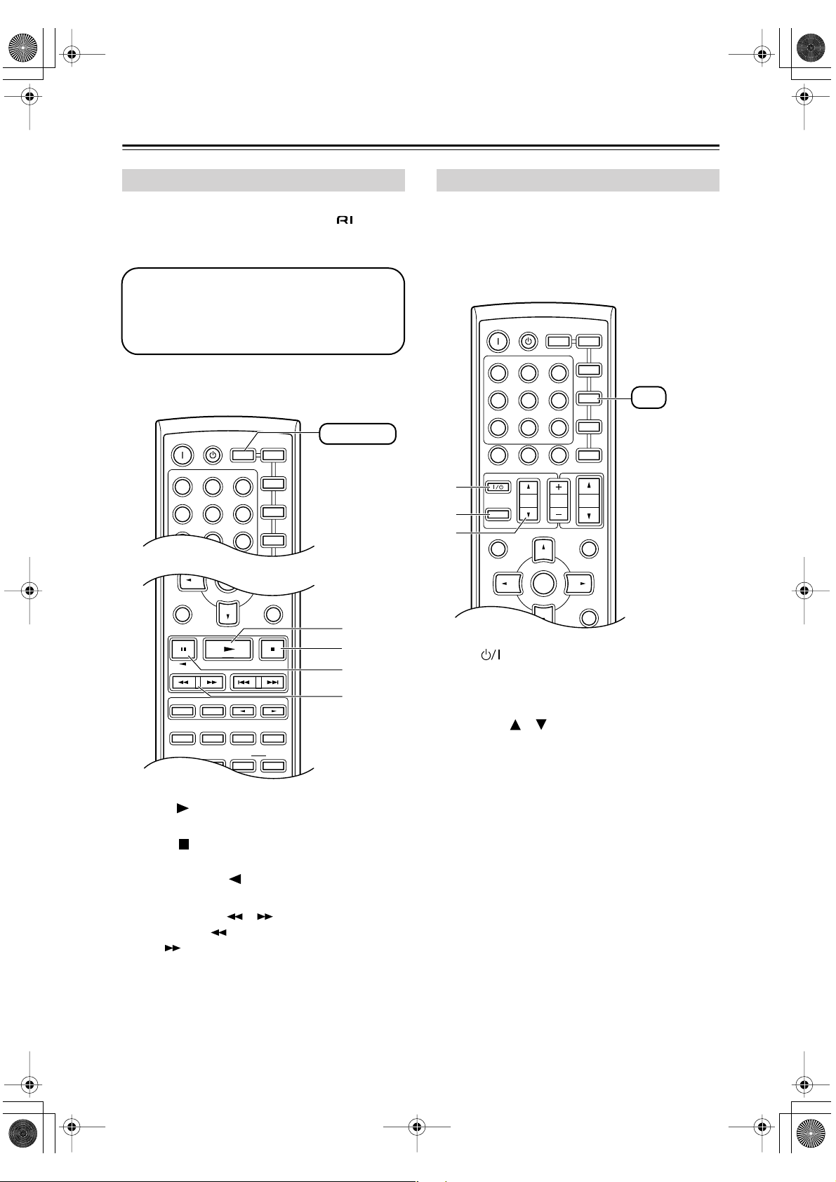
TAPE Mode
TAPE mode is used to control an Onkyo cassette
recorder connected to the AV receiver via .
To set the remote controller to TAPE mode, press the
[RECEIVER] REMOTE MODE button.
Before selecting TAPE mode and starting playback, you should press the [RECEIVER]
REMOTE MODE button followed by the [TAPE]
INPUT SELECTOR button to select your cassette recorder as the input source.
For twin cassette decks, only deck B can be controlled.
ON STANDBY
INPUT SELECTOR
123
V1V2V
456
789
MULTI CH
REMOTE MODE
RECEIVER
TAPE/AMP
DVD
ENTER
3
C DTAPE TUNER
DVD
VCR
M
C D
CDR
TV
RECEIVER
D
TV Control Buttons
The remote controller has dedicated buttons for controlling a TV, which can be used regardless of which remote
controller mode is currently selected. To use these buttons, you must first program the [TV] mode button with
the remote control code appropriate for the TV (see
page 52).
A
B
C
ON STANDBY
INPUT SELECTOR
123
V1V2V
456
789
+
10
10 11 12
--/---
TV
INPUT
GUIDE
TOP MENU
SP A / B
REMOTE MODE
RECEIVER
TAPE/AMP
MULTI CH
0
DIMMER SLEEP
VOL
ENTER
DVD
DISC
C DTAPE TUNER
CLR
CH
DVD
M
D
C D
CDR
3
TV
VCR
SAT
CABLE
TV
You must enter
the appropriate
remote control
code (see
page 52)
VOL
PREVIOUS
MENU
MUTING
SETUPRETURN
A
B
C
LISTENING MODE
SURROUND
STEREO
SUBTITLE
AUDIO REPEAT
TEST TONE
DISPLAY
Play [ ] button
A
CH SEL
PLAY MODE
OR-EQ
RANDOM
LEVEL
L NIGHT
+
-
LEVEL
DVDHDD
CINE FLTR
This button is used to start playback.
B
Stop [ ] button
This button is used to stop playback.
C
Reverse Play [ ] button
This button is used to start reverse playback.
D
Rewind & FF [ ]/[ ] buttons
The Rewind [ ] button is used to start rewind. The
FF [ ] button is used to start fast forward.
D
SETUPRETURN
TV [ ]
A
This sets the TV to On or Standby.
[TV INPUT]
B
This selects inputs on the TV.
TV VOL [ ]/[ ]
C
This adjusts the TV’s volume.
16
Page 17
HT-S780En.book Page 17 Monday, February 28, 2005 2:13 PM
Before Using the AV receiver
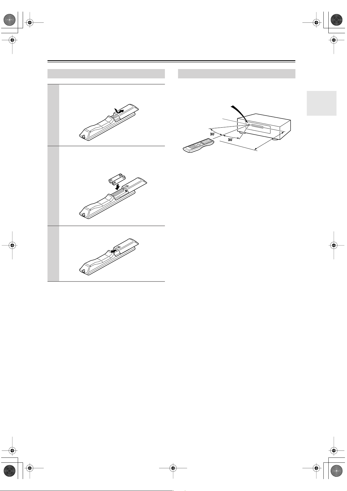
Installing the Batteries
To open the battery compartment, press
1
the small hollow and slide open the cover.
Insert the two supplied batteries (AA/R6)
2
in accordance with the polarity diagram
inside the battery compartment.
Slide the cover shut.
3
Notes:
• The batteries should last for about six months,
although this will vary with usage.
• If the remote controller doesn’t work reliably, try
replacing the batteries.
• Don’t mix new and old batteries or different types of
batteries.
• If you intend not to use the remote controller for a long
time, remove the batteries to prevent damage from
leakage or corrosion.
• Expired batteries should be removed as soon as possible to prevent damage from leakage or corrosion.
Using the Remote Controller
To use the remote controller, point it at the AV receiver’s
remote control sensor, as shown below.
Remote control sensor
AV receiver
STANDBY indicator
Approx. 16 ft.
(5 m)
Notes:
• The remote controller may not work reliably if the AV
receiver is subjected to bright light, such as direct sunlight or inverter-type fluorescent lights. Keep this in
mind when installing.
• If another remote controller of the same type is used in
the same room, or the AV receiver is installed close to
equipment that uses infrared rays, the remote controller may not work reliably.
• Don’t put anything, such as a book, on the remote controller, because the buttons may be pressed inadvertently, thereby draining the batteries.
• The remote controller may not work reliably if the AV
receiver is installed in a rack behind colored glass
doors. Keep this in mind when installing.
• The remote controller will not work if there’s an obstacle between it and the AV receiver’s remote control
sensor.
17
Page 18
HT-S780En.book Page 18 Monday, February 28, 2005 2:13 PM
Connecting Speakers
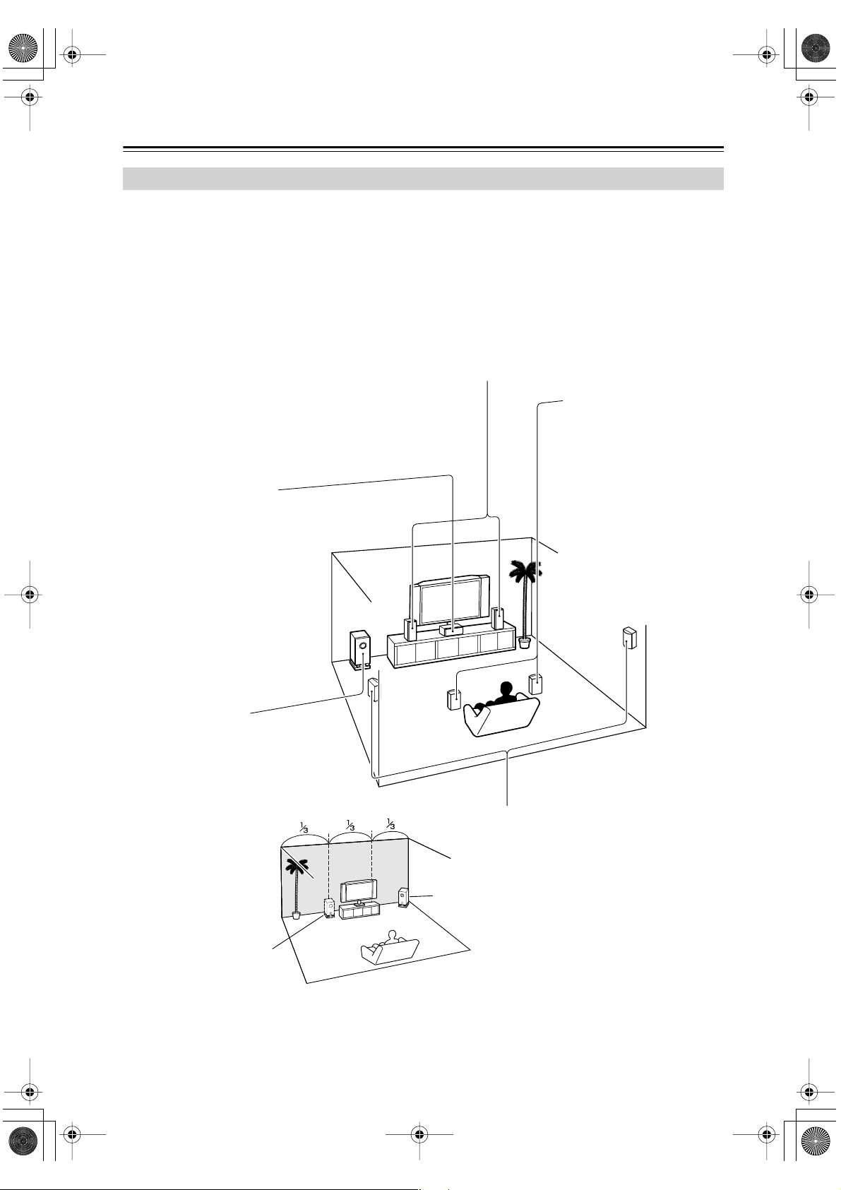
Enjoying Home Theater
You can use two sets of speakers with the AV receiver: speaker set A and speaker set B.
Speaker set A (supplied speakers and subwoofer) should be installed in your main listening room and can be used with
Dolby Digital and DTS surround material. Each speaker must be positioned at a specific location in your listening room
to get the best from surround sound material. The following illustration shows the best positions for your surroundsound speakers. When speaker set B is turned on, speaker set A is reduced to 5.1-channel playback.
Speaker set B can be installed in another room. Speakers can be positioned in the standard position for stereo speakers
or however you like. Speaker set B outputs only analog input signals.
Front left and right speakers (SKF-530 FL/FR)
These output the overall sound. Their role in a home theater is to provide a solid anchor for
the sound image. They should be positioned facing the listener at about ear level, and equidistant from the TV. Angle them inward so as to create a triangle, with the listener at the apex.
Surround back left and right
speakers (SKB-530)
These speakers further
enhance the realism of surround sound and improve
sound localization behind the
Center speaker (SKC-530C)
This speaker enhances the front left
and right speakers, making sound
movements distinct and providing a
full sound image. In movies it’s used
mainly for dialog.
Position it close to your TV (preferably
on top) facing forward at about ear
level, or at the same height as the
front left and right speakers.
listener. They are essential to
enjoy certain listening modes
(i.e., Dolby Digital EX and
DTS-ES). Position them
behind the listener about 2–
3 feet (60–100 cm) above ear
level. Make sure that the listening position is within the
range of the speaker.
Subwoofer (SKW-530)
The subwoofer handles the bass sounds of
the LFE (Low-Frequency Effects) channel.
The volume and quality of the bass output
from your subwoofer will depend on its position, the shape of your listening room, and
your listening position. In general, a good
bass sound can be
obtained by installing the
subwoofer in a front corner,
or at one-third the width of
the wall, as shown.
Corner
1/3 wall
length
Surround left and right speakers
(SFM-530 SL/SR)
These speakers are used for precise sound
positioning and to add realistic ambience.
Position them at the sides of the listener, or
slightly behind, about 2–3 feet (60–100 cm)
above ear level. Ideally they should be equidistant from the listener.
To get the very best from your surround-sound system, you should also specify the distance between the listener and
each individual speaker so that the sound from each speaker arrives at the listener’s ears at the same time (see page 46).
In addition, you should set the level of each individual speaker to achieve an equal balance (see page 47.)
18
Page 19
HT-S780En.book Page 19 Monday, February 28, 2005 2:13 PM
Connecting Speakers —Continued
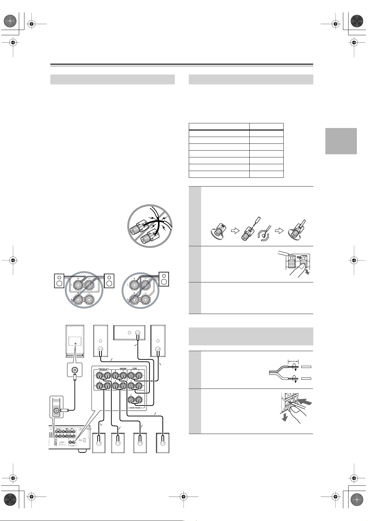
Speaker Connection Precautions
Read the following before connecting your speakers:
•You can connect speakers with an impedance of
8 ohms or higher . If you use speakers with a lower
impedance, and use the amplifier at high volume levels for a long period of time, the built-in protection
circuit may be activated.
• Disconnect the power cord from the wall outlet before
making any connections.
•Pay close attention to speaker wiring polarity. In other
words, connect positive (+) terminals to only positive
(+) terminals, and negative (–) terminals to only negative (–) terminals. If you get them the wrong way
around, the sound will be out of phase and will sound
unnatural.
• Unnecessarily long, or very thin speaker cables may
affect the sound quality and should be avoided.
• Be careful not to short the
positive and negative wires.
Doing so may damage the AV
receiver.
• Don’t connect more than one
cable to each speaker terminal. Doing so may damage the
AV receiver.
• Don’t connect one speaker to several terminals.
Connecting Speaker Set A
The AV receiver’s positive (+) speaker terminals and
speaker’s positive (+) terminals are color-coded for ease
of identification. (The negative (–) speaker terminals are
all black.) Match the color of each cable to the corresponding speaker terminal.
Speaker terminal Color
Front left White
Front right Red
Center Green
Surround left Blue
Surround right Gray
Surround back left Brown
Surround back right Tan
On the AV receiver, unscrew the terminal. Fully
1
insert the bare wires. Make sure that the bare wire
is touching the inside of the pole. Screw the terminal tight.
On the speakers, while pressing
2
the terminal lever, insert the
wire into the hole, and then
release the lever.
PRE OUT
SUB
WOOFER
SKW-530
SKF-530FR
Ta n
Red
SKB-530LSKB-530R
SKC-530C
Green
Brown
SKM-530SR
SKF-530FL
Gray
White
Blue
SKM-530SL
Using the supplied RCA cable, connect the AV
3
receiver’s SUBWOOFER PRE OUT to LINE
INPUT on the subwoofer.
Make sure the cable is plugged all the way.
Connecting Speaker Set B (sold
separately)
Strip 3/8" (10 mm) of insu-
1
lation from the ends of the
speaker cables, and twist
the bare wires tightly, as
shown.
While pressing the lever, insert
2
the wire into the hole, and then
release the lever.
Make sure that the terminals are
gripping the bare wires, not the
insulation.
Note:
When speaker set B is turned on, speaker set A is reduced
to 5.1-channel playback.
3/8" (10 mm)
19
Page 20
HT-S780En.book Page 20 Monday, February 28, 2005 2:13 PM
Connecting Antenna
■
■
This section explains how to connect the supplied indoor
FM antenna and AM loop antenna, and how to connect
commercially available outdoor FM and AM antennas.
The AV receiver won’t pick up any radio signals without
any antenna connected, so you must connect the antenna
to use the tuner.
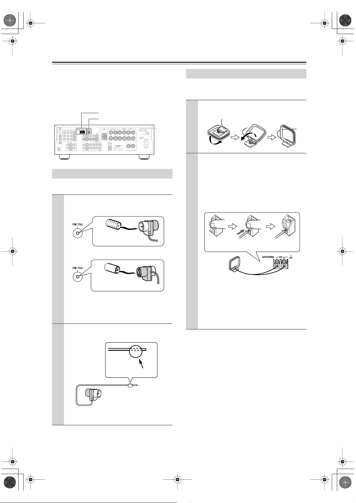
AM antenna push terminals
FM antenna jack
Connecting the Indoor FM Antenna
The supplied indoor FM antenna is for indoor use only.
Attach the FM antenna, as shown.
1
American Model
Insert the plug fully
into the jack.
Connecting the AM Loop Antenna
The supplied indoor AM loop antenna is for indoor use
only.
Assemble the AM loop antenna, inserting
1
the tabs into the base, as shown.
Connect both wires of the AM loop
2
antenna to the AM push terminals, as
shown.
(The antenna’s wires are not polarity sensitive, so
they can be connected either way around).
Make sure that the wires are attached securely and
that the push terminals are gripping the bare
wires, not the insulation.
Push Insert wire Release
Other Models
Insert the plug fully
into the jack.
Once your AV receiver is ready for use, you’ll
need to tune into an FM radio station and adjust
the position of the FM antenna to achieve the best
possible reception.
Use thumbtacks or something similar to
2
fix the FM antenna into position.
Thumbtacks, etc.
Caution: Be careful that you don’t injure yourself
when using thumbtacks.
Once your AV receiver is ready for use, you’ll
need to tune into an AM radio station and adjust
the position of the AM antenna to achieve the best
possible reception.
Keep the antenna as far away as possible from
your AV receiver, TV, speaker cables, and power
cords.
If you cannot achieve good reception with the supplied
indoor AM loop antenna, try using it with a commercially available outdoor AM antenna (see page 21).
If you cannot achieve good reception with the supplied
indoor FM antenna, try a commercially available outdoor FM antenna instead (see page 21).
20
Page 21
HT-S780En.book Page 21 Monday, February 28, 2005 2:13 PM
Connecting Antenna —Continued
■
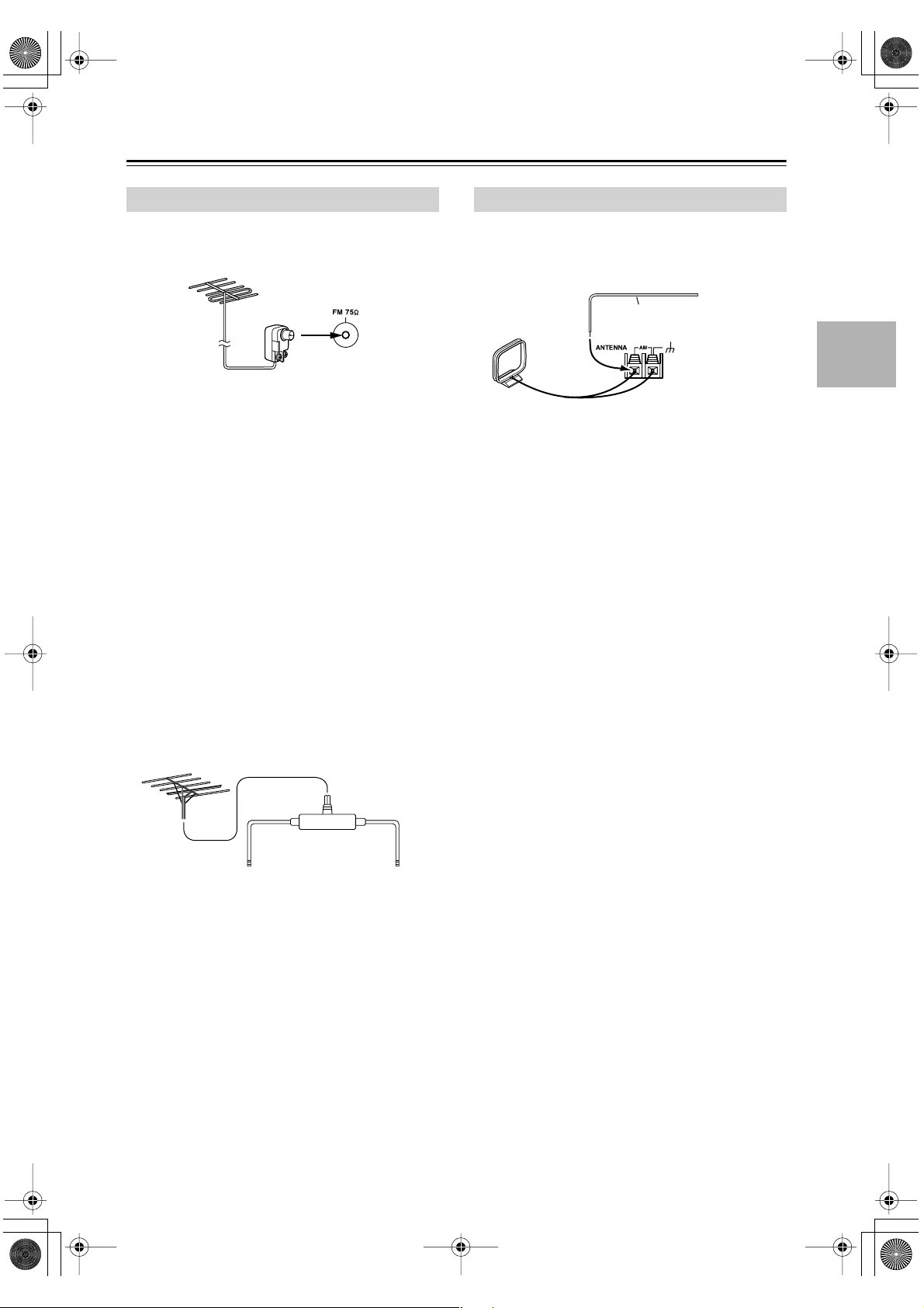
Connecting an Outdoor FM Antenna
If you cannot achieve good reception with the supplied
indoor FM antenna, try a commercially available outdoor FM antenna instead.
Notes:
• Outdoor FM antennas work best outside, but usable
results can sometimes be obtained when installed in an
attic or loft.
•For best results, install the outdoor FM antenna well
away from tall buildings, preferably with a clear line
of sight to your local FM transmitter.
• Outdoor antenna should be located away from possible noise sources, such as neon signs, busy roads, etc.
•For safety reasons, outdoor antenna should be situated
well away from power lines and other high-voltage
equipment.
• Outdoor antenna must be grounded in accordance
with local regulations to prevent electrical shock hazards.
Using a TV/FM Antenna Splitter
It’s best not to use the same antenna for both FM and TV
reception, as this can cause interference problems. If circumstances demand it, use a TV/FM antenna splitter, as
shown.
Connecting an Outdoor AM Antenna
If good reception cannot be achieved using the supplied
AM loop antenna, an outdoor AM antenna can be used in
addition to the loop antenna, as shown.
Outdoor antenna
Insulated antenna cable
AM loop antenna
Outdoor AM antennas work best when installed outside
horizontally, but good results can sometimes be obtained
indoors by mounting horizontally above a window. Note
that the AM loop antenna should be left connected.
Outdoor antenna must be grounded in accordance with
local regulations to prevent electrical shock hazards.
TV/FM antenna splitter
To AV receiver To TV (or VCR)
21
Page 22
HT-S780En.book Page 22 Monday, February 28, 2005 2:13 PM
Connecting Your Components
About AV Connections
• Before making any AV connections, read the manuals
supplied with your other AV components.
• Don’t connect the power cord until you’ve completed
and double-checked all AV connections.
Optical Digital Jacks
The AV receiver’s optical digital jacks have shutter-type
covers that open when an optical plug is inserted and
close when it’s removed. Push plugs in all the way.
Caution: To prevent shutter damage, hold the optical
plug straight when inserting and removing.
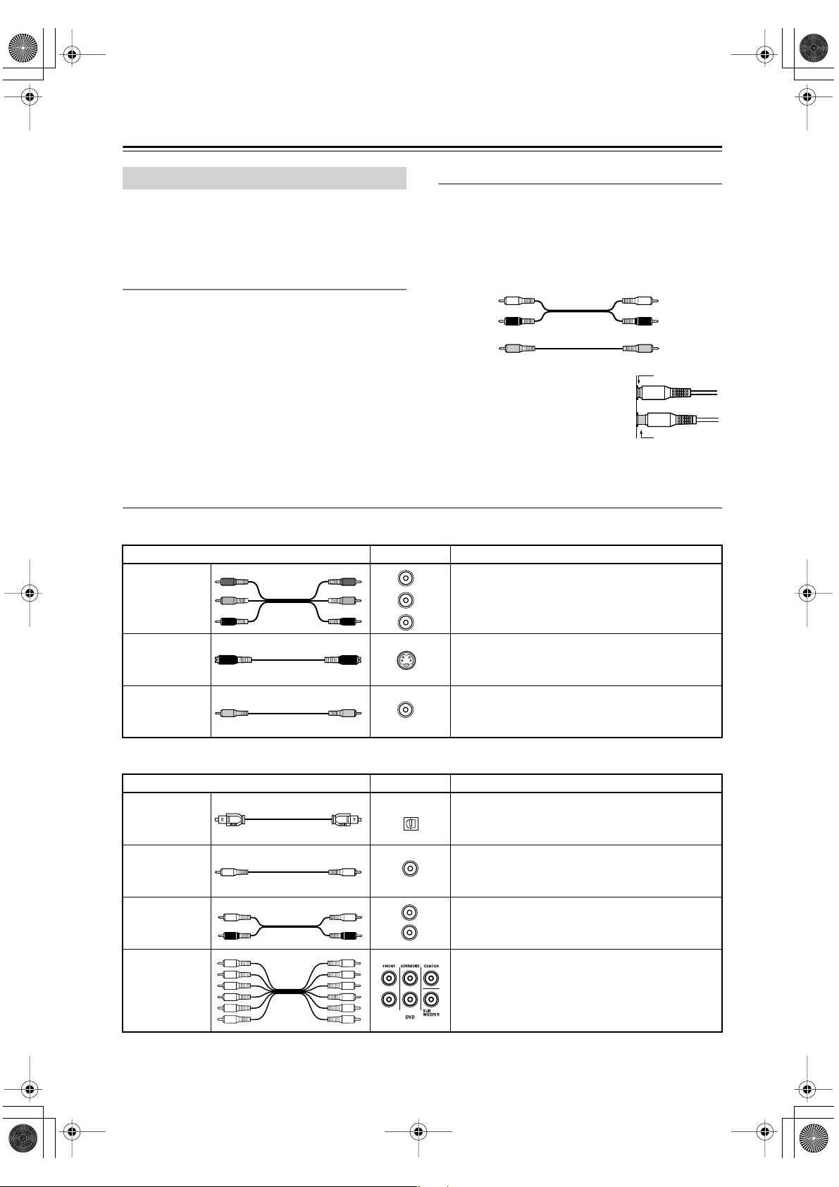
AV Cables & Jacks
Video
Cable Jack Description
Y
Y
P
B
P
B
R
P
PR
Component
video cable
S-Video cable
Composite
video cable
Y
P
B
P
R
AV Connection Color Coding
RCA-type AV connections are usually color coded: red,
white, and yellow. Use red plugs to connect right-channel audio inputs and outputs (typically labeled “R”). Use
white plugs to connect left-channel audio inputs and outputs (typically labeled “L”). And use yellow plugs to
connect composite video inputs and outputs.
Left (white)
Right (red)
(Yellow)
• Push plugs in all the way to make
good connections (loose connections can cause noise or malfunctions).
•To prevent interference, keep
audio and video cables away from
power cords and speaker cables.
Component video separates the luminance (Y) and
color difference signals (P
picture quality. (Some TV manufacturers label their
component video jacks slightly differently.)
S-Video separates the luminance and color signals
S
and provides better picture quality than composite
video.
Composite video is commonly used on TVs, VCRs,
V
and other video equipment. Use only dedicated
composite video cables.
Analog audio
Composite video
, P
R
B
Left (white)
Right (red)
(Yellow)
Right!
Wrong!
), providing the best
Audio
Cable Jack Description
Optical digital
audio cable
Coaxial digital
audio cable
Analog audio
cable (RCA)
Multichannel
analog audio
cable (RCA)
Note: The AV receiver does not support SCART plugs.
22
OPTICAL
COAXIAL
L
R
Offers the best sound quality and allows you to
enjoy surround sound (e.g., Dolby Digital, DTS).
The audio quality is the same as for coaxial.
Offers the best sound quality and allows you to
enjoy surround sound (e.g., Dolby Digital, DTS).
The audio quality is the same as for optical.
This cable carries analog audio. It’s the most common connection format for analog audio and can be
found on virtually all AV components.
This cable carries multichannel analog audio and is
typically used to connect DVD players with a 5.1channel analog audio output. Several standard analog audio cables can be used instead of a multichannel cable.
Page 23

HT-S780En.book Page 23 Monday, February 28, 2005 2:13 PM
Connecting Your Components —Continued
Connecting Both Audio & Video
By connecting both the audio and video outputs of your DVD player and other AV components to the AV receiver, you
can select both the audio and video simultaneously simply by selecting the appropriate input source on the AV receiver.
: Signal Flow
Video
Video
Audio
TV, projector,
etc.
DVD player, etc.
Audio
Speakers (see page 19 for connection
information)
Which Connections Should I Use?
The AV receiver supports several connection formats for compatibility with a wide range of AV equipment. The format
you choose will depend on the formats supported by your other components. Use the following sections as a guide.
For video components, such as a DVD player, you must make two connections—one for audio, one for video.
Video Connection Formats
Video equipment can be connected to the AV receiver
using one of the following video connection formats:
composite video, S-Video, or component video, the latter offering the best picture quality.
When choosing a connection format, bear in mind that
the AV receiver doesn’t convert between formats, so only
outputs of the same format as the input will output the
signal.
For example, if you connect your DVD player to the
S-VIDEO DVD IN, a video signal will be output by the
S-VIDEO MONITOR OUT (for your TV) and the
S-VIDEO VIDEO 1 OUT (for your VCR), but not by
any composite video or component video outputs.
Video Input/Output Diagram
DVD player,
etc.
Output
AV Receiver
OUT
Input
TV,
projector,
etc.
Composite
IN
Composite
Composite
S-Video
S-Video
S-Video
Component
Component
Component
Audio Connection Formats
Audio equipment can be connected to the AV receiver
using the following audio connection formats: analog,
optical, coaxial, and multichannel.
When choosing a connection format, bear in mind that
the AV receiver doesn’t convert between formats.
For example, audio signals connected to an OPTICAL or
COAXIAL digital input are not output by the analog
TAPE OUT, so if you want to record from, for example,
your CD player, in addition to connecting it to a digital
input, you must also connect it to the analog CD IN.
Audio Input/Output Diagram for Recording
CD player,
etc.
Output
IN
AV Receiver
OUT
Input
Cassette
recorder, etc.
Optical
Optical
Coaxial
Coaxial
Analog
Analog
Analog
Multichannel
Multichannel
23
Page 24

a
HT-S780En.book Page 24 Monday, February 28, 2005 2:13 PM
Connecting Your Components —Continued
Connecting a TV or Projector
Step 1: Video Connection
Choose a connection type ( , , or ) that matches the TV, and then make the connection.
A B C
A
COMPONENT VIDEO
Y
P
B
PR
COMPONENT VIDEO
IN
Y
P
B
PR
TV, projector,
etc.
S VIDEO IN
VIDEO IN
MONITOR
OUT
MONITOR
OUT
C
V
B
S
Connection HT-R530 Signal flow TV Picture quality
A
B
C
COMPONENT VIDEO OUT
MONITOR OUT S
MONITOR OUT V
⇒
⇒
⇒
Component video input Best
S-Video input Better
Composite video input Standard
Step 2: Audio Connection
Choose a connection type ( , , or ) that matches the TV, and then make the connection.
Connect one or
the other
a b c
DIGITAL IN
b
COAXIAL
OPTICAL
c
2
L
R
VIDEO 2
a
IN
COAXIAL
OUT
TV, projector,
OPTICAL
OUT
•With the basic connection, you can listen to or record audio from the TV, and listen via speaker set B.
a
•To enjoy Dolby and DTS listening modes, use connection or . (Use and or and for recording.)
etc.
b c a b
L
R
AUDIO
OUT
c
Connection HT-R530 Signal flow TV
a
b
c
VIDEO 2 IN L/R
DIGITAL IN COAXIAL
DIGITAL IN OPTICAL 2
⇐
⇐
⇐
Analog audio L/R output
Digital coaxial output
Digital optical output
Hint!
If your TV has no audio outputs, connect your VCR to the AV receiver and use its tuner.
24
Page 25

b
HT-S780En.book Page 25 Monday, February 28, 2005 2:13 PM
Connecting Your Components —Continued
Connecting a DVD player
Step 1: Video Connection
Choose a connection type ( , , or
A
COMPONENT VIDEO
COMPONENT VIDEO
A B C
DVD IN
PB
PR
OUT
) that matches the DVD player, and then make the connection.
Y
Y
P
B
DVD player
PR
S VIDEO OUT
VIDEO OUT
DVD
DVD
C
V
IN
B
S
IN
The TV must be connected to the AV
receiver with the same
type of connection.
Connection HT-R530 Signal flow DVD player Picture quality
A
B
C
COMPONENT VIDEO DVD IN
DVD IN S
DVD IN V
⇐
⇐
⇐
Component video output
S-Video output Better
Composite video output
Best
Standard
Step 2: Audio Connection
Choose a connection type ( , , , or ) that matches your DVD player, and then make the connection.
Connect one
or the other
•With the basic connection, you can listen to or record audio from a DVD, and listen via speaker set B.
•To enjoy Dolby and DTS listening modes, use connection or . (Use and or and for recording.)
a
b
c
c
COAXIAL
OUT
a b c d
DIGITAL IN
COAXIAL
OPTICAL
1
OPTICAL
OUT
FRONT
L
R
DVD
a
LR
AUDIO
OUT
DVD player
d
FRONT
L
R
FRONT
L
R
c a b a c
SURROUND
DVD
SURR
CENTER
SUB
WOOFER
CENTER
SUB
WOOFER
•To enjoy DVD-Audio or SACD playback from a compatible DVD player with an analog multichannel output,
use connection .
d
Connection HT-R530 Signal flow DVD player
a
b
c
d
DVD IN FRONT
DIGITAL IN COAXIAL
DIGITAL IN OPTICAL 1
DVD IN FRONT, SURROUND,
CENTER, and SUBWOOFER
⇐
⇐
⇐
⇐
Analog audio L/R output
Digital coaxial output
Digital optical output
Analog multichannel output
• If your DVD player has main left and right outputs and multichannel left and right outputs, be sure to use the
main left and right outputs for connection .
a
25
Page 26

a
HT-S780En.book Page 26 Monday, February 28, 2005 2:13 PM
Connecting Your Components —Continued
Connecting a VCR or DVD Recorder for Playback
In addition to video playback, with this hookup example, you can use the VCR’s tuner to listen to the sound of your
favorite TV programs via the AV receiver. This is useful if the TV has no audio outputs.
Step 1: Video Connection
Choose a connection type ( , , or
A B C
TV must be connected to the AV receiver with the same type of connection.
) that matches the VCR/DVD recorder, and then make the connection. The
COMPONENT VIDEO
A
VIDEO 1 IN
Y
P
B
PR
COMPONENT VIDEO
OUT
Y
P
B
PR
VCR,
S VIDEO OUT
VIDEO OUT
VIDEO 1
IN
VIDEO 1
IN
C
V
B
S
DVD recorder
Connection HT-R530 Signal flow VCR/DVD recorder Picture quality
A
B
C
COMPONENT VIDEO VIDEO 1 IN
VIDEO 1 IN S
VIDEO 1 IN V
⇐
⇐
⇐
Component video output
S-Video output Better
Composite video output
Best
Standard
Step 2: Audio Connection
Choose a connection type ( , , or ), and then make the connection.
Connect one
or the other
a b c
DIGITAL IN
b
COAXIAL
OPTICAL
c
2
L
R
VIDEO 1
IN
a
COAXIAL
OUT
OPTICAL
OUT
VCR,
L
R
AUDIO
OUT
DVD recorder
•With the basic connection, you can listen to the VCR/DVD recorder, and listen via speaker set B.
•To enjoy Dolby and DTS listening modes, use connection or . (Use and or and to listen via
a
b c a b
c
speaker set B.)
Connection HT-R530 Signal flow VCR/DVD recorder
a
b
c
VIDEO 1 IN L/R
DIGITAL IN COAXIAL
DIGITAL IN OPTICAL 2
⇐
⇐
⇐
Analog audio L/R output
Digital coaxial output
Digital optical output
26
Page 27

HT-S780En.book Page 27 Monday, February 28, 2005 2:13 PM
Connecting Your Components —Continued
Connecting a VCR or DVD Recorder for Recording
Step 1: Choose a video connection type ( or ) that matches the VCR/DVD recorder, and make the connection.
A B
The video source that you want to record must be connected to the AV receiver with the same type of connection.
Step 2: Make audio connection
.
a
VIDEO 1
B
V
a
L
R
VIDEO 1
AUDIO
IN
L
R
VCR,
DVD recorder
S VIDEO IN
VIDEO IN
Connection HT-R530 Signal flow VCR/DVD recorder Picture quality
A
B
a
VIDEO 1 OUT S
VIDEO 1 OUT V
VIDEO 1 OUT L/R
⇒
⇒
⇒
VIDEO 1
S-Video input
A
S
Better
Composite video input Standard
Audio L/R input
—
Connecting a Camcorder, Games Console, or Other Device
Step 1: Make video connection .
Step 2: Make audio connection .
TUNING / PRESET
RETURN
DIMMER MEMORY
TUNING MODE
CLEAR
TAPE TUNER CD
A
ENTER
SETUP
VIDEO 3 INPUT
A
a
MASTER VOLUME
a
VIDEO 3 INPUT
AUDIO
LR
VIDEO
VIDEO 3 INPUT
LR
AUDIO
LR
AUDIO
OUT
VIDEO OUT
Camcorder, games console,
etc.
Connection HT-R530 Signal flow Camcorder/console
A
a
VIDEO 3 INPUT
VIDEO 3 INPUT L/R
⇐
⇐
Composite video output
Analog audio L/R output
27
Page 28

a
HT-S780En.book Page 28 Monday, February 28, 2005 2:13 PM
Connecting Your Components —Continued
Connecting a Satellite, Cable, Set-top box, or Other Video Source
Step 1: Video Connection
Choose a connection type ( , , or
A B C
) that matches the video source, and then make the connection.
COMPONENT VIDEO
A
VIDEO 2 IN
Y
P
B
PR
COMPONENT VIDEO
OUT
Y
P
B
PR
Satellite, cable,
set-top box, etc.
VIDEO 2
V
IN
VIDEO 2
S
IN
S VIDEO OUT
VIDEO OUT
C
The TV must be con-
B
nected to the AV
receiver with the same
type of connection.
Connection HT-R530 Signal flow Video source Picture quality
A
B
C
COMPONENT VIDEO VIDEO 2 IN
VIDEO 2 IN S
VIDEO 2 IN V
⇐
⇐
⇐
Component video output
S-Video output Better
Composite video output
Best
Standard
Step 2: Audio Connection
Choose a connection type ( , , or ) that matches the video source, and then make the connection.
a b c
b
DIGITAL IN
28
c
COAXIAL
OUT
COAXIAL
OPTICAL
2
OPTICAL
OUT
Satellite, cable,
IN
L
R
VIDEO 2
L
R
AUDIO
OUT
a
Connect one
or the other
set-top box, etc.
•With the basic connection, you can listen to or record audio from the video source, and listen via speaker
a
set B.
•To enjoy Dolby and DTS listening modes, use connection or . (Use and or and for recording.)
Connection HT-R530 Signal flow Video source
a
b
c
VIDEO 2 IN L/R
DIGITAL IN COAXIAL
DIGITAL IN OPTICAL 2
b c a b
⇐
⇐
⇐
Analog audio L/R output
Digital coaxial output
Digital optical output
c
Page 29

■
c
■
■
HT-S780En.book Page 29 Monday, February 28, 2005 2:13 PM
Connecting Your Components —Continued
Connecting a CD Player or Turntable
CD Player, or Turntable with Built-in Phono Preamp
Step 1:
Choose a connection type ( , , or ) that matches the CD player, or choose for a turntable with a built-in phono
preamp, and then make the connection.
a b c a
IN
L
R
CD
a
Turntable (MM) with
built-in phono
AUDIO
OUTPUT
Connect one
or the other
b
c
COAXIAL
OUT
DIGITAL IN
COAXIAL
OPTICAL
1
OPTICAL
OUT
IN
L
R
CD
a
LR
AUDIO
OUT
CD player
preamp
•With the basic connection, you can listen to or record audio from the CD player or turntable, and listen via
a
speaker set B.
•To connect the CD player digitally, use connection or . (Use and or and for recording.)
Connection HT-R530 Signal flow CD or turntable
a
b
c
CD IN L/R
DIGITAL IN COAXIAL
DIGITAL IN OPTICAL 1
Turntable with no Phono Preamp Built-in
A phono preamp is necessary to connect a turntable that
doesn’t have a phono preamp built-in.
b
⇐
⇐
⇐
a b a c
Analog audio L/R output
Digital coaxial output
Digital optical output
Turntable with an MC (Moving Coil) Cartridge
An MC head amp and phono preamp are necessary to
connect a turntable with an MC (Moving Coil) cartridge.
L
R
AUDIO
AUDIO
IN
L
R
CD
OUTPUT
AUDIO
OUTPUT
L
R
Phono preamp
L
R
AUDIO
INPUT
L
R
IN
L
R
CD
OUTPUT
L
R
Phono
preamp
AUDIO
INPUT
L
R
MC head amp or
MC transformer
AUDIO
OUTPUT
L
R
AUDIO
OUTPUT
AUDIO
INPUT
L
R
L
R
29
Page 30

a
HT-S780En.book Page 30 Monday, February 28, 2005 2:13 PM
Connecting Your Components —Continued
Connecting a Cassette, CDR, MiniDisc, or DAT Recorder
Step 1:
Choose a connection type ( , , or ) that matches the recorder, and then make the connection.
a b c
DIGITAL IN
b
Connect one
or the other
•With the basic connection, you can play and record with the recorder, and listen via speaker set B.
a
•To connect the recorder digitally for playback purposes, use connections and or and .
Connection HT-R530 Signal flow Cassette/CDR/MD/DAT recorder
a
b
c
DIGITAL IN OPTICAL 3
COAXIAL
OPTICAL
c
3
COAXIAL
OUT
OPTICAL
OUT
TAPE IN L/R
TAPE OUT L/R
DIGITAL IN COAXIAL
Cassette recorder, CDR,
etc.
⇐
⇒
⇐
⇐
a b
Analog audio L/R output
Analog audio L/R input
Digital coaxial output
Digital optical output
OUT
TAPE
L
R
IN OUT
REC PLAY
IN
L
R
L
R
Connecting the Power Cord of Another Component
The AV receiver has an AC outlet on its rear panel for
connecting the power cord of another AV component.
The other component’s power switch can then be left in
the ON position so that it turns on or off when the AV
receiver is set to On or Standby.
a
c
Caution:
• Make sure that the capacity of the component that
you connect to the AC OUTLET does not exceed
the stated capacity (e.g., 100 W).
Notes:
• Onkyo components with jacks should be connected directly to wall outlets, not the AV
receiver’s AC OUTLET.
• The socket type and capacity will depend on the
country in which you purchased the AV receiver.
American model
30
Page 31

•
HT-S780En.book Page 31 Monday, February 28, 2005 2:13 PM
Connecting Your Components —Continued
Connecting Onkyo Components
Step 1: Be sure that the Onkyo component is connected to the AV receiver with an analog audio cable (RCA).
Step 2: Make the connection.
With (Remote Interactive) you can use the following special functions:
Auto Power On/Standby
When you start playback on a component connected via , if the AV receiver is in Standby, it will turn on and select
that component as the input source automatically. Similarly, when the AV receiver is set to Standby, all components
connected via will also enter Standby. This function will not work if a component’s power cord is connected to the
AV receiver’s AC OUTLET.
Direct Change
When playback is started on a component connected via , the AV receiver automatically selects that component as
the input source. If the DVD player is connected to the AV receiver’s multichannel input, you must press the
[MULTI CH] button (see page 35) to listen to all channels because the Direct Change function selects only the DVD
IN FRONT jacks.
Remote Control
You can control other -compatible Onkyo components by pointing the remote controller at the AV receiver’s remote
control sensor. You must enter the appropriate remote control code first (page 53).
Notes:
• Use only cables for connections.
cables are supplied with Onkyo players (DVD,
CD, etc.).
• Some components have two jacks, you can
connect either one to the AV receiver. The other is
for connecting additional -compatible compo-
REMOTE
CONTROL
L
R
FRONT
nents.
• Connect the AV receiver’s jack to only Onkyo
components. Connecting to other manufacturer’s
components may cause them to malfunction.
• Some components may not support all functions. Refer to the manuals supplied with your
components.
e.g., CD player
e.g., DVD player
ANALOG
AUDIO OUT
ANALOG
AUDIO OUT
LR
LR
Connecting the Power Cord
Notes:
Before connecting the power cords, connect all of your speakers and AV components.
•Turning on the AV receiver and subwoofer may cause a momentary power surge that might interfere with other
electrical equipment on the same circuit. If this is a problem, plug them into a different branch circuit.
IN
CD
L
R
DVD
31
Page 32

HT-S780En.book Page 32 Monday, February 28, 2005 2:13 PM
Turning On
STANDBY/ON
STANDBY indicator
STANDBY/ON
STANDBY
A SPEAKERS B
PHONES
PURE AUDIO
+
TONE
STEREO
MULTl CH DVD VIDEO 1 VIDEO 2
VCR
LISTENING MODE
DISPLAY
DIGITAL INPUT
RT/PTY/TP MEMORY
VIDEO 3 TAPE TUNER CD
Turning On the AV Receiver
1
AV receiver
STANDBY/ON
Remote
controller
or
Press the [STANDBY/ON] button.
Alternatively, press the remote controller’s [RECEIVER] button followed
by the [ON] button.
The AV receiver comes on, the display lights up, and the STANDBY indicator goes off.
To turn the AV receiver off, press the [STANDBY/ON] button, or the remote controller’s [STANDBY] button. The AV receiver will enter Standby mode. To prevent any
loud surprises the next time you turn on the AV receiver, always turn down the volume
before turning it off.
CLEAR
TUNING MODE
TUNING / PRESET
ENTER
RETURN
STANDBY
ON
RECEIVER
MASTER VOLUME
SETUP
VIDEO 3 INPUT
VIDEO
AUDIO
LR
ON STANDBY
TAPE/AMP
INPUT SELECTOR
123
V1V2V
456
MULTI CH
789
+
0
10
10 11 12
--/---
DIMMER SLEEP
TV
VOL
INPUT
GUIDE
TOP MENU
REMOTE MODE
RECEIVER
3
DVD
C DTAPE TUNER
CLR
CH
DISC
PREVIOUS
MENU
DVD
VCR
SAT
VOL
C D
TV
CABLE
M
D
CDR
To turn on the subwoofer, press its [POWER] switch to the ON position (not North
American models).
Smooth Operation in a Few Easy Steps
To ensure smooth operation, here’s a few easy steps to help you configure the AV receiver before you use it for the
very first time. These settings only need to be made once.
■ Have you connected a component to a digital audio input?
If you have, see “Assigning Digital Inputs to Input Sources” on
page 33.
■ Have you connected an Onkyo MD recorder or CD recorder to the TAPE IN/OUT jacks?
If you have, see “Changing the TAPE/MD/CDR Display” on
page 33.
TESTING THE SPEAKERS
To test that all of the speakers are working properly, press the remote controller’s [TEST TONE] button. The
test tone will be output by each speaker in turn and the name of each speaker will appear on the display. To turn off
the test tone, press the [TEST TONE] button again.
• If the test tone is not produced by a speaker, or it’s produced by a speaker other than that shown on the display,
you may have wired the speakers incorrectly and you should check your connections (see page 19).
COAX
OPT1
OUT IN
TAPE
CD recorder / MD recorder
32
Page 33

HT-S780En.book Page 33 Monday, February 28, 2005 2:13 PM
First Time Setup
Assigning Digital Inputs to Input
Sources
2, 3
STANDBY/ON
A SPEAKERS B
TUNING / PRESET
STANDBY
+
TONE
LISTENING MODE
DISPLAY
DIGITAL INPUT
PHONES
PURE AUDIO
STEREO
MULTl CH DVD VIDEO 1 VIDEO 2
VCR
VIDEO 3 TAPE TUNER CD
RT/PTY/TP MEMORY
RETURN
TUNING MODE
CLEAR
MASTER VOLUME
ENTER
SETUP
VIDEO 3 INPUT
VIDEO
AUDIO
LR
1
To enjoy Dolby Digital and DTS, you must connect your
DVD player to the AV receiver by using a digital audio
connection (coaxial or optical).
With this function, you can assign digital inputs to input
sources. For example, if you connect your DVD player
to DIGITAL IN OPTICAL 1, you’ll need to assign that
input (OPT1) to the DVD input source.
You can change the assignments as follows.
Note:
Make sure you also set your digital sources to send out a
digital signals. Please refer to the digital sources’ manual.
1
DVD VIDEO 1 VIDEO 2
VCR
VIDEO 3 TAPE TUNER
CD
Press the input selector button
for the source that you want to
assign.
(Digital inputs cannot be assigned to
the TUNER input source.)
Changing the TAPE/MD/CDR Display
If you connect an -compatible Onkyo MiniDisc
recorder or CD recorder to the TAPE IN/OUT jacks, for
to work properly, you must change this setting.
This setting can only be changed on the AV receiver.
STANDBY/ON
A SPEAKERS B
PHONES
STANDBY
PURE AUDIO
+
TONE
STEREO
MULTl CH DVD VIDEO 1 VIDEO 2
VCR
LISTENING MODE
DISPLAY
DIGITAL INPUT
VIDEO 3 TAPE TUNER CD
RT/PTY/TP MEMORY
TUNING / PRESET
RETURN
TUNING MODE
CLEAR
MASTER VOLUME
ENTER
SETUP
VIDEO 3 INPUT
VIDEO
AUDIO
LR
1, 2
1
2
TAPE
TAPE
Press the [TAPE] input selector
button so that “TAPE” appears
on the display.
Press and hold down the [TAPE]
input selector button (about 3
seconds) to set the display.
Repeat this step to select TAPE, MD, or
CDR.
2
DIGITAL INPUT
Press the [DIGITAL INPUT]
button.
The current assignment appears.
3
DIGITAL INPUT
Press the [DIGITAL INPUT] button repeatedly to select COAX,
OPT1, OPT2, OPT3, or “– – – –”
(analog).
By default, the DVD input source is assigned to
[COAX].
33
Page 34

HT-S780En.book Page 34 Monday, February 28, 2005 2:13 PM
Playing Your AV Components
Basic AV Receiver Operation
4
MASTER VOLUME
SETUP
VIDEO 3 INPUT
VIDEO
AUDIO
LR
STANDBY/ON
A SPEAKERS B
2
PHONES
STANDBY
TONE
MULTl CH DVD VIDEO 1 VIDEO 2
PURE AUDIO
MULTI CH
+
STEREO
VCR
DISPLAY
LISTENING MODE
DISPLAY
DIGITAL INPUT
RT/PTY/TP MEMORY
VIDEO 3 TAPE TUNER CD
1
TUNING / PRESET
ENTER
RETURN
TUNING MODE
CLEAR
ON STANDBY
REMOTE MODE
DVD
RECEIVER
TAPE/AMP
1
2
INPUT SELECTOR
123
V1V2V
456
MULTI CH
789
+
10
0
10 11 12
--/---
DIMMER SLEEP
TV
VOL
INPUT
GUIDE
TOP MENU
SP A / B
ENTER
3
DVD
C DTAPE TUNER
CLR
CH
DISC
PREVIOUS
MUTING
1
M
D
C D
CDR
TV
VCR
SAT
CABLE
VOL
4
MENU
Subwoofer’s
rear panel
MIN
OUTPUT LEVEL
MAX
1
AV receiver
DVD VIDEO 1 VIDEO 2
VCR
VIDEO 3 TAPE TUNER
CD
2
AV receiver
A SPEAKERS B
3
Remote
controller
Remote
controller
Use the AV receiver’s input selector buttons to select the input source.
To select the input source with the remote controller, press the
[RECEIVER] button, and then use the INPUT SELECTOR buttons.
On the remote controller, the [V1], [V2], and [V3] buttons select the VIDEO 1,
VIDEO 2, and VIDEO 3 input sources respectively.
Use the SPEAKERS [A] and [B] buttons on the AV receiver or the [SP A/B]
button on the remote controller to select the speaker set that you want to
use.
Pressing the remote controller’s [SP A/B] button cycles through the following settings:
Speaker Set A
→
Speaker Set A&B
→
Speaker Set B
→
Off.
The A and B speaker indicators show whether
each speaker set is on or off.
Indicators
Note that when speaker set B is turned on, speaker
set A is reduced to 5.1-channel playback.
Start playback on the source component.
When you select DVD or another video component, on your TV you’ll need to select
the video input that’s connected to the AV receiver’s MONITOR OUT.
34
4
AV receiver
5
MASTER VOLUME
Remote
controller
VOL
To adjust the volume, use the MASTER VOLUME control, or the remote
controller’s [VOL] button.
The volume can be set to MIN, 1 through 79, or MAX. The AV receiver is designed for
home theater enjoyment and has a wide volume range for precise adjustment.
To set the level of the subwoofer, use the OUTPUT LEVEL control.
Because our ears are less sensitive to very low bass sounds, there’s a temptation to set
the level of the subwoofer too high. As a rule of thumb, set the subwoofer level to what
you think is the optimal level, and then back it off slightly.
Select a suitable listening mode and enjoy!
See page 40.
Page 35

HT-S780En.book Page 35 Monday, February 28, 2005 2:13 PM
Playing Your AV Components —Continued
MULTI CH
DISPLAY
ON STANDBY
V1V2V
+
--/---
INPUT
STEREO
AUDIO REPEAT
TEST TONE
DISPLAY
REMOTE MODE
RECEIVER
TAPE/AMP
INPUT SELECTOR
123
456
789
10
DVD
MULTI CH
CLR
0
10 11 12
DIMMER SLEEP
CH
TV
VOL
DISC
LISTENING MODE
SURROUND
RANDOM
SUBTITLE
CH SEL
LEVEL
PLAY MODE
L NIGHT
OR-EQ
-
RC
608M
3
C DTAPE TUNER
-
DVD
C D
TV
VCR
SAT
CABLE
VOL
LEVEL
DVDHDD
CINE FLTR
M
D
CDR
+
RECEIVER
Displaying Source Information
You can display various information about the current
input source as follows.
Press the [RECEIVER] button,
and then press the [DISPLAY]
button repeatedly to cycle
through the available information.
The following information can typically be displayed for
input sources.
Input source &
volume
Signal format*
or sampling
frequency
Using the Multichannel Input
The multichannel input is for connecting a component
with individual 5.1-channel analog audio output jacks,
such as a DVD player or MPEG decoder. See page 25 for
hookup information.
Press the [RECEIVER] button followed by the [MULTI CH] button
so that MULTI CH indicator
appears on the display.
Audio from the multichannel input will
now be used for the DVD input source.
MULTI CH indicator
Note:
• While the multichannel input is selected, the Speaker
Configuration settings on page 48 are ignored, and
signals from the multichannel input are fed to the front
left, front right, center, surround left, and surround
right speakers and subwoofer regardless of those settings.
Input source &
listening mode
*If the input signal is analog, no format information is
displayed. If the input signal is PCM, the sampling frequency is displayed. If the input signal is digital but not
PCM, the signal format is displayed. Information is displayed for about three seconds, then the previously displayed information reappears.
Interpreting Surround Channel Information
ABC
A: The number of front channels (front left, front right,
and center).
B: The number of surround channels (surround left and
surround right). If there’s surround back channel
information, this number will be 3.
C: LFE channel for subwoofer (1 means yes).
35
Page 36

HT-S780En.book Page 36 Monday, February 28, 2005 2:13 PM
Using the Tuner
■
■
Listening to the Radio
TUNING MODE
TUNING
RT/PTY/TP MEMORY
TUNING / PRESET
RETURN
TUNING MODE
CLEAR
TUNER
STANDBY/ON
A SPEAKERS B
STANDBY
+
STEREO
TONE
LISTENING MODE
DISPLAY
PHONES
PURE AUDIO
MULTl CH DVD VIDEO 1 VIDEO 2
DIGITAL INPUT
VIDEO 3 TAPE TUNER CD
VCR
With the built-in tuner, you can enjoy AM and FM radio
stations. You can store your favorite stations as presets
for quick selection.
1
TUNER
Use the [TUNER] input selector
button to select either AM or FM.
In this example, FM has been selected.
Band Frequency
(Actual display depends on country.)
AM Frequency Step Setup
(not North American model)
Here you can specify the AM frequency step used in
your area. When this setting is changed, all radio presets
are deleted.
1
2
3
Press the [SETUP] button and
use the Up and Down [ ]/[ ]
buttons to select “0. Hardware
Setup,” and then press [ENTER].
Use the Up and Down [ ]/[ ]
buttons to select “AM Freq,” and
then use the Left and Right
[ ]/[ ] buttons to select:
10 kHz: Select if 10 kHz steps are
used in your area.
9 kHz: Select if 9 kHz steps are used
in your area.
Press the [SETUP] button.
Setup closes.
MASTER VOLUME
ENTER
SETUP
VIDEO 3 INPUT
VIDEO
AUDIO
LR
Tuning into Radio Stations
Auto Tuning Mode
1
TUNING MODE
2
TUNING / PRESET
ENTER
When tuned into a station, the TUNED indicator
appears. When tuned into a stereo FM station, the FM
STEREO indicator appears on the display, as shown.
Manual Tuning Mode
1
TUNING MODE
2
TUNING / PRESET
ENTER
The American model changes FM frequency in 0.2 MHz
steps, 10 kHz steps for AM. For other models it’s
0.05 MHz steps for FM and 9 kHz steps for AM.
In Manual Tuning mode, FM stations will be in mono.
Tuning into weak FM stereo stations
If the signal from a stereo FM station is weak, it may be
impossible to get good reception. In this case, switch to
Manual Tuning mode and listen to the station in mono.
Press the [TUNING MODE] button
so that the AUTO indicator
appears on the display.
Press the TUNING Up or Down
[ ]/[ ] button.
Searching stops when a station is
found.
AUTOTUNED
FM STEREO
Press the [TUNING MODE] button
so that the AUTO indicator disappears from the display.
Press and hold the TUNING Up or
Down [ ]/[ ] button.
The frequency stops changing when
you release the button.
Press the buttons repeatedly to change
the frequency one step at a time.
Note:
• This procedure can also be performed on the remote
controller by using its [SETUP] button, arrow buttons,
and [ENTER] button.
36
Page 37

HT-S780En.book Page 37 Monday, February 28, 2005 2:13 PM
Using the Tuner —Continued
Presetting Radio Stations
2, 4
STANDBY/ON
STANDBY
A SPEAKERS B
PHONES
You can store up to 30 of your favorite radio stations as
presets.
1
2
MEMORY
3
TUNING / PRESET
ENTER
4
MEMORY
+
TONE
LISTENING MODE
DISPLAY
DIGITAL INPUT
STEREO
PURE AUDIO
MULTl CH DVD VIDEO 1 VIDEO 2
VIDEO 3 TAPE TUNER CD
VCR
Tune into the station that you
want to store as a preset.
Press the [MEMORY] button.
The MEMORY indicator appears and
the preset number flashes.
While the MEMORY indicator is
displayed (about 8 seconds), use
the PRESET [ ]/[ ] buttons to
select a preset from 1 through 30.
In this example, preset #3 is selected.
Press the [MEMORY] button
again to store the station.
The station is stored and the preset
number stops flashing.
Repeat this procedure for all your
favorite radio stations.
RT/PTY/TP MEMORY
3
TUNING / PRESET
RETURN
TUNING MODE
CLEAR
MASTER VOLUME
ENTER
SETUP
VIDEO 3 INPUT
VIDEO
AUDIO
LR
Deleting Presets
2
STANDBY/ON
STANDBY
A SPEAKERS B
PHONES
1
+
TONE
LISTENING MODE
DISPLAY
DIGITAL INPUT
RT/PTY/TP MEMORY
TUNING MODE
CLEAR
PURE AUDIO
STEREO
MULTl CH DVD VIDEO 1 VIDEO 2
VCR
VIDEO 3 TAPE TUNER CD
Select the preset that you want to
delete.
See the previous section.
2
MEMORY
CLEAR
While holding down the [MEMORY] button, press the
TUNING MODE
[TUNING MODE] button.
The selected preset is deleted and its
number disappears from the display.
Displaying Radio Information
1
STANDBY/ON
STANDBY
1
A SPEAKERS B
PHONES
DISPLAY
+
TONE
LISTENING MODE
DISPLAY
DIGITAL INPUT
RT/PTY/TP MEMORY
TUNING MODE
CLEAR
PURE AUDIO
STEREO
MULTl CH DVD VIDEO 1 VIDEO 2
VCR
VIDEO 3 TAPE TUNER CD
Press the [DISPLAY] button
repeatedly to cycle through the
available information.
TUNING / PRESET
RETURN
TUNING / PRESET
RETURN
MASTER VOLUME
ENTER
SETUP
VIDEO 3 INPUT
VIDEO
AUDIO
LR
MASTER VOLUME
ENTER
SETUP
VIDEO 3 INPUT
VIDEO
AUDIO
LR
Selecting Preset Stations
STANDBY/ON
STANDBY
1
A SPEAKERS B
PHONES
TUNING / PRESET
ENTER
+
TONE
LISTENING MODE
DISPLAY
DIGITAL INPUT
RT/PTY/TP MEMORY
VIDEO 3 TAPE TUNER CD
PURE AUDIO
STEREO
MULTl CH DVD VIDEO 1 VIDEO 2
VCR
Use the PRESET [ ]/[ ] buttons, or the remote controller’s
CH [+/–] button to select a preset.
Band, preset # &
frequency
1
TUNING / PRESET
RETURN
TUNING MODE
CLEAR
MASTER VOLUME
ENTER
SETUP
VIDEO 3 INPUT
VIDEO
AUDIO
LR
Listening mode
37
Page 38

HT-S780En.book Page 38 Monday, February 28, 2005 2:13 PM
Common Functions
■
■
This chapter explains functions that can be used with any
input source.
DIMMER
CH SEL
OR-EQ
ON STANDBY
V1V2V
+
--/---
INPUT
GUIDE
TOP MENU
SP A / B
STEREO
AUDIO REPEAT
TEST TONE
DISPLAY
REMOTE MODE
RECEIVER
TAPE/AMP
INPUT SELECTOR
123
456
789
10
MULTI CH
DVD
CLR
0
10 11 12
DIMMER SLEEP
CH
TV
VOL
DISC
ENTER
LISTENING MODE
SURROUND
RANDOM
SUBTITLE
CH SEL
LEVEL
PLAY MODE
L NIGHT
OR-EQ
-
RC
608M
3
C DTAPE TUNER
-
DVD
C D
TV
VCR
SAT
CABLE
VOL
PREVIOUS
MENU
MUTING
SETUPRETURN
LEVEL
DVDHDD
CINE FLTR
M
D
CDR
+
Press
[RECEIVER]
first
SLEEP
MUTING
LEVEL – +
Adjusting the Bass & Treble
You can adjust the bass or treble for the front speakers
except when the Direct or Pure Audio (not North American model) listening mode is selected.
1
TONE
Press the AV receiver’s [TONE]
button repeatedly to select either
Bass or Treble.
2
Use the TONE [–]/[+] buttons to
+
adjust.
Bass
You can boost or cut low-frequency sounds output by the
front speakers from –10 dB to +10 dB in 2 dB steps.
Treble
You can boost or cut high-frequency sounds output by
the front speakers from –10 dB to +10 dB in 2 dB steps.
Muting the AV Receiver
With this function, you can temporarily mute the output
of the AV receiver.
TONE, –, +
STANDBY/ON
A SPEAKERS B
TUNING / PRESET
STANDBY
+
TONE
LISTENING MODE
DISPLAY
DIGITAL INPUT
PHONES
STEREO
MULTl CH DVD VIDEO 1 VIDEO 2
VCR
VIDEO 3 TAPE TUNER CD
DIMMER MEMORY
RETURN
TUNING MODE
CLEAR
MASTER VOLUME
ENTER
SETUP
VIDEO 3 INPUT
VIDEO
AUDIO
LR
PHONES DIMMER
Setting the Display Brightness
With this function, you can adjust the brightness of the
display.
AV receiver
DIMMER
Remote
controller
Press the [DIMMER] button
repeatedly to select: dim, dimmer, or normal brightness.
Press the remote controller’s
[MUTING] button.
The output is muted and the MUTING
indicator flashes on the display, as
shown.
To unmute the AV receiver, press the remote control-
ler’s [MUTING] button again, or adjust the volume. The
output is unmuted and the MUTING indicator goes off.
Muting is cancelled when the AV receiver is set to
Standby.
Using the OptiResponse Equalizer
When using the HT-R530 with the speakers included in
this Package, by turning on the OptiResponse equalizer,
you can enjoy a powerful sound with movies or music.
OR-EQ
Press the remote controller’s
[OR-EQ] button to turn the OptiResponse equalizer on or off.
38
Page 39

HT-S780En.book Page 39 Monday, February 28, 2005 2:13 PM
Common Functions —Continued
■
■
■
Using the Sleep Timer
With the sleep timer, you can set the AV receiver so that
it automatically turns off after a set period.
Press the remote controller’s
[SLEEP] button repeatedly to
select the required sleep time.
You can set the sleep time from 90 to 10
minutes in 10 minute steps.
The SLEEP indicator appears on the
display when the sleep timer has been
set, as shown. The specified sleep time
appears on the display for about five
seconds, then the previous display
reappears.
SLEEP indicator
To cancel the sleep timer, press the [SLEEP] button
repeatedly until the SLEEP indicator disappears.
To check the remaining sleep time, press the [SLEEP]
button. Note that if you press the [SLEEP] button while
the sleep time is being displayed, you’ll shorten the sleep
time by 10 minutes.
Using Headphones
You can connect a pair of stereo headphones (1/4-inch
phone plug) to the AV receiver’s PHONES jack for private listening, as shown.
STANDBY/ON
A SPEAKERS B
PHONES
PURE AUDIO
Adjusting Speaker Levels
You can adjust the level of each speaker in speaker set A
while listening to an input source. These temporary
adjustments are cancelled when the AV receiver is set to
Standby.
1
Notes:
•You cannot use this function while the AV receiver is
muted.
• Speakers that are set to No or None in the Speaker
Configuration cannot be adjusted.
Speaker Set B
While speaker set B is on, you can also adjust the levels
of the left and right speakers in speaker set B, from
–12 dB to +12 dB.
• These settings are stored when the AV receiver is set
to Standby.
• While speaker set B is on, you cannot adjust the levels
of speaker set A’s surround back speakers.
Headphones
While a pair of headphones is connected, you can adjust
the volume of the left and right channels individually,
from –12 dB to +12 dB each.
Use the remote controller’s
[CH SEL] button to select each
speaker, and use the [LEVEL–]
and [LEVEL+] buttons to adjust
the volume.
You can adjust the volume of each
speaker from –12 dB to +12 dB
(–15 dB to +12 dB for the subwoofer).
Notes:
•Always turn down the volume before connecting your
headphones.
• Speaker sets A and B are turned off while the headphones plug is inserted in the PHONES jack.
• When you connect a pair of headphones, the listening
mode is set to Stereo, unless it’s already set to Pure
Audio, Mono, Stereo, or Direct.
• When the multichannel DVD input is selected, only
the front left and front right channels can be heard in
the headphones.
• These settings are stored when the AV receiver is set
to Standby.
Multichannel DVD Input
While the multichannel DVD input is selected, you can
adjust the level of each 5.1 channel input individually,
from –12 dB to +12 dB. (–30 to +12 dB for the subwoofer.)
• These settings are stored when the AV receiver is set
to Standby.
• Individual speaker levels can also be adjusted in
“3. MultiLevel Setup” (see page 47).
39
Page 40

HT-S780En.book Page 40 Monday, February 28, 2005 2:13 PM
Using the Listening Modes
■
■
■
■
■
■
Selecting Listening Modes
See “About the Listening Modes” on page 42 for
detailed information about the listening modes.
• The Dolby Digital and DTS listening modes
can only be selected if your DVD player is
connected to the AV receiver with a digital
audio connection (coaxial or optical).
• Listening mode availability depends on the
format of the current input signal.
• While a pair of headphones is connected,
you can select only the Pure Audio (not
North American model), Mono, Direct, or
Stereo listening mode.
Selecting on the AV receiver
RT/PTY/TP MEMORY
TUNING / PRESET
RETURN
TUNING MODE
CLEAR
STANDBY/ON
A SPEAKERS B
PHONES
STANDBY
PURE AUDIO
+
TONE
STEREO
MULTl CH DVD VIDEO 1 VIDEO 2
VCR
LISTENING MODE
DISPLAY
DIGITAL INPUT
VIDEO 3 TAPE TUNER CD
PURE AUDIO
STEREO
LISTENING MODE
[PURE AUDIO] button (not North American
model)
This button selects the Pure Audio listening mode.
When this mode is selected, the AV receiver outputs
no video signals and its display is turned off.
MASTER VOLUME
ENTER
SETUP
VIDEO 3 INPUT
VIDEO
LR
Selecting with the Remote Controller
CH
TV
VOL
INPUT
GUIDE
TOP MENU
SP A / B
SURROUND
LISTENING MODE
SURROUND
STEREO
STEREO
SUBTITLE
AUDIO REPEAT
TEST TONE
CH SEL
PLAY MODE
DISPLAY
OR-EQ
[STEREO] button
AUDIO
This button selects the Stereo listening mode.
[SURROUND] button
This button selects the Dolby Digital and DTS listening modes.
LISTENING MODE [ ]/[ ] buttons
Pressing these buttons repeatedly cycles through all
of the listening modes that can be used with the current input source.
RC
ENTER
-
RANDOM
LEVEL
L NIGHT
608M
VOL
DISC
PREVIOUS
MENU
MUTING
SETUPRETURN
+
-
LEVEL
DVDHDD
CINE FLTR
,
40
[STEREO] button
This button selects the Stereo listening mode.
LISTENING MODE [ ]/[ ] buttons
Pressing these buttons repeatedly cycles through all
of the listening modes that can be used with the current input source.
Page 41

HT-S780En.book Page 41 Monday, February 28, 2005 2:13 PM
Using the Listening Modes —Continued
The following table lists all the listening modes and shows which modes can be selected for each input signal format.
*2
DTS-ES
Discrete Matrix
*5
✔
✔
✔
Input signal format
Source
Listening mode
Pure Audio (not North
American model)
Direct
Stereo
Mono
Multich
PLIIx Movie/Music/Game
Neo:6 Cinema
Neo:6 Music
Dolby
DTS
Onkyo
Original
DSP
*4
Dolby D
Dolby D EX
Dolby D+PLIIx Music
Dolby D+PLIIx Movie
DTS, DTS 96/24
DTS-ES Discrete
DTS-ES Matrix
DTS+Neo:6
DTS+Dolby EX
DTS+PLIIx Music
DTS+PLIIx Movie
Mono Movie
Orchestra
Unplugged
Studio-Mix
TV Logic
All Ch Stereo
Full Mono
*3
*4
Analog,
*1
PCM
CD, TV, VHS,
MD,
turntable,
radio,
cassette,
DTV, etc.
*/2
Dolby D
2/0
(Stereo)
1/0,1+1 Other 3/2.1
DVD, DTV, etc. DVD, CD, etc. DVD
✔ ✔✔✔✔✔✔ ✔ ✔
✔ ✔✔✔✔✔✔ ✔
✔✔ ✔
✔✔
✔
✔
✔ ✔✔✔✔✔✔ ✔
DTS/DTS 96/24
2/0
(Stereo)
✔
✔
✔
*1. In the Pure Audio and Direct listening modes, PCM signals at 32 kHz, 44.1 kHz, and 48 kHz are processed at 64 kHz, 88.2 kHz,
and 96 kHz respectively. 96 kHz signals are processed at 48 kHz for all listening modes other than Pure Audio, Direct, and Stereo.
*2. In the Pure Audio, Direct, Stereo, and DTS 96/24 listening modes, signals are processed as DTS 96/24. Everything else is pro-
cessed as DTS.
*3. If the Surr Back parameter is set to “None,” or speaker set B is on, PLII is used.
*4. Available only when Surround speakers are connected.
*5. If the Surr Back setting is set to “None,” or speaker set B is on, DTS is used.
Multich
✔
: Not available when the Surr Back parameter is set to None, or when speaker set B is on.
: Not available when the Surr Back parameter is set to None or 1ch, or when speaker set B is on.
Tip: You can check the format of the digital input signal on page 35, “Displaying Source Information.”
41
Page 42

HT-S780En.book Page 42 Monday, February 28, 2005 2:13 PM
Using the Listening Modes —Continued
About the Listening Modes
With its built-in surround-sound decoders and DSP programs, the AV receiver can transform your home listening room into a movie theater or concert hall.
The AV receiver’s surround indicators show which
speakers are active in each listening mode.
Front left Center Front right
Subwoofer
left
Surround
back left/
Surround
Direct
The selected input source is output directly with minimal
processing for a pure sound.
Pure Audio (not North American model)
As an extension of Direct mode, this mode turns off the
display, turns off the power to the video circuitry, and
minimizes any other possible noise sources, providing a
high fidelity sound that’s true to the original. (Since the
power to the video circuitry is turned off, no video signals are output while this mode is selected.)
Stereo
The selected input source is processed as a stereo signal
and output by the front left and right speakers and the
subwoofer.
Mono
Use this mode when watching an old movie with a mono
soundtrack, or to select multilingual soundtracks
recorded in the left and right channels of some movies.
It can also be used when playing a DVD or other source
with multiplexed audio, such as a karaoke DVD.
Dolby Pro Logic II Movie
Use this mode with DVDs and videos that bear the Dolby Surround
logo or TV shows that feature Dolby Surround. You can
also use this mode with stereo movies or TV shows and
the AV receiver will create a 5.1 surround mix from the
2-channel stereo.
Dolby Pro Logic II Music
Use this mode to add 5.1 surround to stereo sources such
as music CDs and DVDs.
right
Surround
right
Dolby Pro Logic IIx
If you’ve connected surround back speakers to the AV
receiver, Dolby Pro Logic IIx allows you to enjoy 7.1channel playback from 2-channel or 5.1-channel music
or movies. Dolby Pro Logic IIx provides a well defined,
natural multichannel surround-sound experience, putting the listener in a seamless envelope of sound. The
added drama and natural sound enhance the listening
experience with CDs, movies, and games.
Dolby Pro Logic IIx has three modes of operation:
Movie mode for movies, Music mode for listening to
music, and Game mode for use with games consoles
with 2-channel stereo outputs.
Dolby Digital
With this format you can experience the
same superb sound that you get at a movie
theater or concert hall. Use this mode with DVDs that
bear the Dolby Digital logo.
Dolby Digital EX
With an added surround-back channel,
this 6.1 channel format offers a heightened
sense of space, for added realism with moving sounds,
such as those that rotate 360 degrees or pass overhead.
Dolby Digital EX material can also be played on conventional 5.1 channel systems, in which case the surroundback channel audio is split between the surround left and
right channels. Use this mode with DVDs that have a
5.1-channel soundtrack and bear the Dolby Digital logo.
DTS
This digital surround format offers a surround sound experience with exceptional
fidelity. It uses compressed digital audio
data, with six discrete channels (5.1), and the
ability to handle large amounts of audio data while
remaining faithful to the original. DTS provides very
high-quality sound. You’ll need a DTS compatible DVD
player in order to enjoy DTS material. Use this mode
with DVDs and CDs that bear the DTS logo.
DTS 96/24
This mode provides higher audio quality.
Use it with CDs and DVDs that bear the
DTS 96/24 logo.
DTS-ES Discrete
This is DTS with an added surround back
channel for 6.1 surround sound. Use it with
program material recorded in DTS 6.1 format. With the
additional surround back channel, this format offers 6.1
fully independent digital channels, providing a realistic
sense of movement and space. Use it with program material recorded in DTS 6.1, such as CDs and DVDs that
bear the DTS-ES logo.
42
Page 43

HT-S780En.book Page 43 Monday, February 28, 2005 2:13 PM
Using the Listening Modes —Continued
DTS-ES Matrix
This is DTS with an added surround back
channel for 6.1 surround sound. Use it to
provide 6.1 channel surround playback
with program material recorded in DTS 5.1
format. Since DTS 5.1 program material
contains surround back channel information, all channels can be reconstructed for 6.1-channel
playback. Use this mode with CDs and DVDs that bear
the DTS-ES or DTS logo.
Neo:6
This mode provides 6.1-channel playback from 2-channel sources. It offers six full-bandwidth channels with
excellent separation. There are two modes of operation:
Cinema mode for movies, and Music mode for listening
to music.
Cinema mode simulates the realistic sense of movement
that you get with 6.1-channel surround sound sources.
Use this mode with videos, DVDs, and TV shows that
feature stereo sound.
Music mode uses the surround channels to simulate a
natural sound field that cannot be produced with conventional stereo. Use this mode with stereo material such as
music CDs.
Onkyo Original DSP Modes
Mono Movie
This mode is suitable for use with old movies and other
mono sound sources. The center speaker outputs the
sound as it is, while reverb is applied to the sound output
by the other speakers, giving presence to even mono
material.
Orchestra
Suitable for classical or operatic music. The surround
channels are emphasized in order to widen the stereo
image. In addition, it simulates the natural reverberation
of a large hall.
Unplugged
Suitable for acoustic instrument sounds, vocals, and jazz
music. By emphasizing the front stereo image, it simulates the stage-front experience.
Studio-Mix
Suitable for rock and pop music. Listening to music in
this mode creates a lively sound field with a powerful
acoustic image, like being at a club or rock concert.
TV Logic
Adds realistic acoustics to TV shows produced in a TV
studio. In addition, it adds surround effects to the entire
sound and adds clarity to voices.
All Ch Stereo
Ideal for background music. The front, surround, and
surround back channels create a stereo image that fills
the entire listening area.
Full Mono
In this mode, all speakers output mono audio, so the
music sounds the same regardless of where you are.
43
Page 44

HT-S780En.book Page 44 Monday, February 28, 2005 2:13 PM
Adjusting the Listening Modes
ON STANDBY
ENTER
TAPE/AMP
INPUT SELECTOR
123
V1V2V
456
MULTI CH
789
+
0
10
10 11 12
--/---
DIMMER SLEEP
TV
VOL
INPUT
GUIDE
TOP MENU
SP A / B
ENTER
REMOTE MODE
RECEIVER
3
DVD
C DTAPE TUNER
CLR
CH
DISC
PREVIOUS
MENU
MUTING
SETUPRETURN
DVD
M
C D
CDR
TV
VCR
SAT
CABLE
VOL
D
RECEIVER
SETUP
Using the CinemaFILTER
With the CinemaFILTER, you can soften overly bright
movie soundtracks, which are typically mixed for reproduction in a movie theater.
CinemaFILTER can be used with the following listening
modes: Dolby Digital, Dolby Digital EX, Dolby Pro
Logic II Movie, Dolby Pro Logic IIx Movie, DTS,
DTS-ES, DTS Neo:6 Cinema, DTS 96/24, DTS+Neo:6,
and DTS+Dolby EX.
1
Press the [RECEIVER] button,
and then press the [CINE FLTR]
button repeatedly to select:
On: CinemaFILTER on.
Off: CinemaFILTER off.
LISTENING MODE
SURROUND
STEREO
RANDOM
SUBTITLE
AUDIO REPEAT
TEST TONE
CH SEL
PLAY MODE
DISPLAY
OR-EQ
LEVEL
L NIGHT
+
-
LEVEL
DVDHDD
CINE FLTR
CINE FLTR
L NIGHT
-
RC
608M
Using the Late Night Function
(Dolby Digital only)
With the Late Night function, you can reduce the
dynamic range of Dolby Digital material so that you can
still hear quiet parts even when listening at low volume
levels—ideal for watching movies late at night when you
don’t want to disturb anyone.
1
Press the [RECEIVER] button,
and then press the [L NIGHT] button repeatedly to select:
Off: Late Night function off.
Low: Small reduction in dynamic
range.
High: Big reduction in dynamic
range.
Using the Audio Adjust Functions
These functions only work with speaker set A.
Audio Adjust provides various functions for adjusting
the sound.
1
2
Press the [RECEIVER] button followed by the [SETUP] button.
Use the Up and Down [ ]/[ ]
buttons to select “4. Audio
Adjust,” and then press the
[ENTER] button.
Notes:
• The effect of the Late Night function depends on the
Dolby Digital material that you are playing, and with
some material there will be little or no effect.
• The Late Night function is set to Off when the AV
receiver is set to Standby.
44
Page 45

■
HT-S780En.book Page 45 Monday, February 28, 2005 2:13 PM
Adjusting the Listening Modes —Continued
■
L:
R:
■
■
■
■
■
3
4
5
The Audio Adjust functions are explained below.
Use the Left and Right [ ]/[ ]
buttons to change the settings.
Press the Down [ ] button to
select the next setting.
Repeat step 3 to complete all settings.
Press the [SETUP] button.
Setup closes.
Input Channel Settings
Multiplex
This setting determines which channel is output from a
stereo multiplex source. Use it to select audio channels
or languages with multiplex sources, multilingual TV
broadcasts, and so on.
Main: The main channel is output (default).
Sub: The sub channel is output.
M/S: Both the main and sub channels are output.
Mono (2ch)
This setting determines which channel is output when
the Mono listening mode is used with a stereo source.
L+R: Both the left and right channels are output
(default).
Only the left channel is output.
Only the right channel is output.
PL II & PL IIx Music Mode Settings
These settings apply to only 2-channel (stereo) sources.
Panorama
With this function, you can broaden the width of the
front stereo image when using the Pro Logic II Music or
Pro Logic IIx Music listening mode.
On: Panorama function on.
Off: Panorama function off (default).
If the stereo image feels too wide, or there’s too much
surround sound, move the sound field forward to
improve the balance. Conversely, if the stereo image
feels like it’s in mono, or there’s not enough surround
sound, move it backward.
Center Width
With this function, you can adjust the width of the sound
from the center speaker when using the Pro Logic II
Music or Pro Logic IIx Music listening mode. Normally
if you’re using a center speaker, the center channel sound
is output by only the center speaker. (If you’re not using
a center speaker, the center channel sound will be distributed to the front left and right speakers to create a phantom center). This setting controls the front left, right, and
center mix, allowing you to adjust the weight of the center channel sound. It can be adjusted from 0 to 7 (default
is 3).
DTS Neo:6 Music Mode Setting
Center Image
The DTS Neo:6 Music listening mode creates 6-channel
surround sound from 2-channel (stereo) sources. With
this setting, you can specify by how much the front left
and right channel output is attenuated in order to create
the center channel. It can be adjusted from 0 to 5 (default
is 3). This setting is unavailable if no surround speakers
are connected.
When set to 0, the front left and right channel output is
attenuated by half (–6 dB), giving the impression that the
sound is located centrally. This setting works well when
the listening position is considerably off center. When
set to 5, the front left and right channels are not attenuated, maintaining the original stereo balance.
Dolby Digital EX Input Signal Setting
Dolby D EX
This setting determines how Dolby Digital EX signals
are handled. This setting is unavailable if no surround
back speakers are connected or speaker B is on.
Auto: If the source signal contains a Dolby Digital
EX flag, the Dolby Digital EX listening mode
is used (default).
Manual: You can select Pro Logic IIx Movie, Pro
Logic IIx Music, Dolby Digital, or Dolby
Digital EX.
Dimension
With this setting, you can move the sound field forward
or backward when using the Pro Logic II Music or Pro
Logic IIx Music listening mode. The default setting is 3.
Higher settings move the sound field forward. Lower settings move it backward.
45
Page 46

HT-S780En.book Page 46 Monday, February 28, 2005 2:13 PM
Advanced Setup
Advanced Speaker Settings
The advanced speaker settings cannot be
changed while headphones are connected,
Speaker set B is on, or the multichannel input
is being used.
ENTER
ON STANDBY
V1V2V
+
--/---
INPUT
GUIDE
TOP MENU
SP A / B
STEREO
AUDIO REPEAT
TEST TONE
DISPLAY
REMOTE MODE
RECEIVER
TAPE/AMP
INPUT SELECTOR
123
456
789
10
MULTI CH
DVD
C DTAPE TUNER
CLR
0
10 11 12
DIMMER SLEEP
CH
TV
VOL
DISC
ENTER
LISTENING MODE
SURROUND
RANDOM
SUBTITLE
CH SEL
LEVEL
PLAY MODE
L NIGHT
OR-EQ
-
608M
RC
3
-
DVD
C D
TV
VCR
SAT
CABLE
VOL
PREVIOUS
MENU
MUTING
SETUPRETURN
LEVEL
DVDHDD
CINE FLTR
M
D
CDR
SETUP
+
RECEIVER
3
4
5
6
Use the Up and Down [ ]/[ ]
buttons to select “2. Sp Distance,” and then press the
[ENTER] button.
While “Unit” is displayed, use the
Left and Right [ ]/[ ] buttons to
select “feet” or “meters”.
feet: Distances in feet. Can be set
from 1 to 30 feet in 1-foot
steps.
meters: Distances in meters. Can be
set from 0.3 to 9 meters in
0.3-meter steps.
Use the Down [ ] button to
select “Front,” and use the Left
and Right [ ]/[ ] buttons to
specify the distance for the “front
speakers,” then press the Down
[] button to select the next
speaker.
Repeat step 5 for all speakers.
Note:
Speakers that you set to No or None in
the Speaker Configuration (page 48)
cannot be selected.
Speaker Distance
To get the best from surround sound, it’s important that
the sound from each speaker reaches the listener at the
same time. To achieve this, you need to specify the distance from each speaker to the listening position.
1
Measure and make a note of the
distance from each speaker to
the listening position.
2
Press the [RECEIVER] button followed by the [SETUP] button on
the remote controller.
46
7
Press the [SETUP] button.
Setup closes.
Notes:
• The Center and Subwoofer distances can be set up to
5 ft. (1.5 m) more or less than the Front distance. For
example, if the Front distance is set to 20 ft. (6 m), the
Center and Subwoofer distances can be set between 15
and 25 ft. (4.5 and 7.5 m).
• The Surround and Surround Back distances can be set
up to 5 ft. (1.5 m) more or 15 ft. (4.5 m) less than the
Front distance. For example, if the Front distance is set
to 20 ft. (6 m), the SurrRight, Surr Left, Surr Back R,
and Surr Back L distances can be set between 5 and 25
ft. (1.5 and 7.5 m).
Page 47

HT-S780En.book Page 47 Monday, February 28, 2005 2:13 PM
Advanced Setup —Continued
Speaker Levels
With this function, you can adjust the volume of each
speaker so that all speakers can be heard equally at the
listening position.
Speaker levels cannot be adjusted while the
AV receiver is muted.
1
2
Press the [RECEIVER] button followed by the [SETUP] button on
the remote controller.
Use the Up and Down [ ]/[ ]
buttons to select “3. Level Cal,”
and then press the [ENTER] button.
A pink noise test tone is output by the
front left speaker.
6
Note:
•A quicker way to adjust the speaker levels is to press
the remote controller’s [TEST TONE] button to output
the test tone, use the [LEVEL–] and [LEVEL+] buttons to adjust the levels, and use the [CH SEL] button
to select the speakers.
• If the multichannel input is selected (page 35), in step
2, the “3. MultiLevel” menu appears instead of the
“3. Level Cal” menu, and you can adjust the level of
each channel of the multichannel input regardless of
the Speaker Configuration settings.
Press the [SETUP] button.
Setup closes.
Don’t forget to turn down the volume if
you turned it up while setting the levels.
3
4
5
Turn up the volume so that you
can hear the test tone sufficiently.
While each speaker outputs the test
tone, its name appears on the display, as
shown.
Use the Left and Right [ ]/[ ]
buttons to adjust the speaker
level, and use the Down [ ] button to select the next speaker.
The level can be adjusted from –12 to
+12 dB in 1 dB steps (–15 to +12 dB
for the subwoofer).
Repeat step 4 so that the level of
the test tone from each speaker
is the same.
Speakers that you set to No or None in
the Speaker Configuration (page 48) do
not output the test tone.
47
Page 48

HT-S780En.book Page 48 Monday, February 28, 2005 2:13 PM
Advanced Setup —Continued
No .
Speaker Configuration, Crossover Frequency,
and Double Bass settings only need to be
changed if you’re not using the speakers in
this package.
Speaker Configuration
This section explains how to specify which speakers are
connected and their sizes.
For speakers with a cone diameter
larger than 6-1/2 inches (16 cm),
specify Large
smaller diameter, specify Small
1
2
3
.
For those with a
.
Cone diameter
Press the [RECEIVER] button followed by the [SETUP] button.
Use the Up and Down [ ]/[ ]
buttons to select “1. Speaker
Config,” and then press the
[ENTER] button.
While the Subwoofer setting is
selected, use the Left and Right
[ ]/[ ] buttons to select Yes or
Yes: Select if a subwoofer is con-
nected.
No: Select if no subwoofer is con-
nected.
4
5
6
Use the Down [ ] button to
select “Front,” and then use the
Left and Right [ ]/[ ] buttons to
select Small or Large .
Small: Select if the front speakers are
small.
Large: Select if the front speakers are
large.
Note:
• If the Subwoofer setting in step 3 is
set to No, this setting is fixed at Large
and does not appear.
Use the Down [ ] button to
select “Center,” and then use the
Left and Right [ ]/[ ] buttons to
select Small , Large , or None .
Small: Select if the center speaker is
small.
Large: Select if the center speaker is
large.
None: Select if no center speaker is
connected.
Note:
• If the Front setting in step 4 is set to
Small, the Large option cannot be
selected.
Use the Down [ ] button to
select “Surround,” and then use
the Left and Right [ ]/[ ] buttons to select Small , Large , or
None .
Small: Select if the surround speak-
ers are small.
Large: Select if the surround speak-
ers are large.
None: Select if no surround speakers
are connected.
Note:
• If the Front setting in step 4 is set to
Small, the Large option cannot be
selected.
48
Page 49

HT-S780En.book Page 49 Monday, February 28, 2005 2:13 PM
Advanced Setup —Continued
7
8
Use the Down [ ] button to
select “Surr Back,” and use the
Left and Right [ ]/[ ] buttons to
select Small , Large , or None .
Small: Select if the surround back
speakers are small.
Large: Select if the surround back
speakers are large.
None: Select if no surround back
speakers are connected.
Notes:
• If the Surround setting in step 6 is set
to None, this setting does not appear.
• If the Surround setting in step 6 is set
to Small, the Large option cannot be
selected.
Use the Down [ ] button to
select “Surr Back Ch,” and use
the Left and Right [ ]/[ ] buttons to select 2ch or 1ch .
2ch: Select if two (left and right)
surround back speakers are
connected.
1ch: Select if one surround back
speaker is connected.
Note:
• If the Surround and Surr Back settings in steps 6 and 7 are set to None,
this setting does not appear.
Continue with step 9 of the “Crossover
Frequency” setting.
Crossover Frequency
To get the best bass performance from your speaker system, you need to set the crossover frequency according
to the size and frequency response of your subwoofer
and other speakers (front, center, and surround).
9
Use the Down [ ] button to
select “Crossover,” and then use
the Left and Right [ ]/[ ] buttons to select a crossover frequency.
Choose a crossover frequency suitable
for your setup.
If you’re using a subwoofer, choose a
crossover frequency based on the diameter of your front speakers.
If you’re not using a subwoofer, use
the diameter of the first speaker that
you specified as Small in steps 4
through 7 in the “Speaker configuration” setting (see page 48).
Speaker cone
diameter
Over 8 in.
(20 cm)
6-1/2 to 8 in.
(16–20 cm)
5-1/4 to 6-1/2 in.
(13–16 cm)
3-1/2 to 5-1/4 in.
(9–13 cm)
Under 3-1/2 in.
(9 cm)
Continue with step 10 of the “Double
Bass” setting.
Note:
•For a more accurate setting, listen to some music that
you know well and choose a higher crossover frequency if you think there’s not enough sound coming
from the subwoofer; a lower setting if you think
there’s too much.
Crossover
frequency
60Hz
80Hz
100Hz
120Hz
150Hz
Double Bass
With the Double Bass function, you can boost bass output by feeding bass sounds from the front left and right
channels to the subwoofer. This function can be set only
if the Subwoofer setting (step 3) is set to Yes, and the
Front setting (step 4) is set to Large in the Speaker Configuration on page 48.
10
11
Use the Down [ ] button to
select “Double Bass,” and then
use the Left and Right [ ]/[ ]
buttons to select:
On: Double Bass function on.
Bass from the front left and
right channels is also fed to
the subwoofer (default).
Off: Double Bass function off.
Press the [SETUP] button.
Setup closes.
49
Page 50

HT-S780En.book Page 50 Monday, February 28, 2005 2:13 PM
Advanced Setup —Continued
Digital Input Signal Formats
The following table shows the display indicators for each
supported digital signal format.
Format Display
Dolby Digital
DTS
PCM
Normally, the AV receiver detects the signal format automatically. However, if you experience either of the following issues when playing PCM or DTS material, you
can manually set the signal format to PCM or DTS:
• If the beginnings of tracks from a PCM source are cut
off, try setting the format to PCM.
• If noise is produced when fast forwarding or reversing
a DTS CD, try setting the format to DTS.
PCM
RT/PTY/TP MEMORY
TUNING / PRESET
ENTER
RETURN
SETUP
TUNING MODE
CLEAR
STANDBY/ON
A SPEAKERS B
STANDBY
+
TONE
LISTENING MODE
DISPLAY
DIGITAL INPUT
PHONES
PURE AUDIO
STEREO
MULTl CH DVD VIDEO 1 VIDEO 2
VCR
VIDEO 3 TAPE TUNER CD
DIGITAL INPUT
Press and hold the AV receiver’s [DIGITAL
1
INPUT] button for about 3 seconds.
While “Auto” is displayed (about 3 sec-
2
onds), press the [DIGITAL INPUT] button
again to select: PCM, DTS, or Auto.
DTS or PCM: The DTS or PCM indicator,
depending on which format you have set, flashes,
and only signals in that format are output. Digital
signals in other formats are ignored.
Auto (default): The format is detected automati-
cally. If no digital input signal is present, the corresponding analog input is used instead.
MASTER VOLUME
VIDEO 3 INPUT
VIDEO
AUDIO
LR
50
Page 51

VIDEO
VIDEO 3 INPUT
AUDIO
LR
HT-S780En.book Page 51 Monday, February 28, 2005 2:13 PM
Recording
1.
2.
3.
4.
5.
This chapter explains how to record the selected input
source to an AV component with recording capability,
and how to record audio and video from two different
sources.
Recording the Input Source
You can record only to AV components that are connected to the TAPE OUT or VIDEO 1 OUT jacks.
See pages 22–31 for information on connecting your AV
components to the AV receiver.
1
DVD VIDEO 1 VIDEO 2
VCR
VIDEO 3 TAPE TUNER
CD
Remote
controller
Use the input selector buttons to
select the AV component that
you want to record.
Audio signals from the selected input
source are output by the VIDEO 1 OUT
and TAPE OUT jacks.
You can listen to the source while
recording. The AV receiver’s VOLUME control has no effect on recording.
Recording from Different AV Sources
With this function, you can record audio and video from
different sources, allowing you to overdub audio onto
your video recordings. This function takes advantage of
the fact that when an audio-only input source (i.e.,
TAPE, TUNER, or CD) is selected, the video input
source remains unchanged. For example, if you first
select the VIDEO 3 input source, followed by the CD
input source, you can watch the video from the VIDEO 3
input and listen to the audio from the CD input.
In the following example, audio from the CD player connected to the CD IN jacks, and video from the camcorder
connected to the VIDEO 3 INPUT VIDEO jack are
recorded by the VCR, which is connected to the
VIDEO 1 OUT jacks.
Camcorder
video signal
audio signal
2
3
Notes:
•You cannot record from AV components that are connected to the digital inputs. You must use analog connections.
• The surround effects produced by the surround and
DSP listening modes cannot be recorded.
•You cannot record from an AV component that is connected to the multichannel input.
• If you select another input source while recording, that
input source will be recorded instead.
• While the Pure Audio listening mode is selected, the
VIDEO 1 OUT V and S jacks don’t output video signals, so select another mode when recording.
Start recording on the AV component connected to the TAPE OUT
or VIDEO 1 OUT jacks.
Start playback on the source AV
component.
VCRCD player
Prepare the camcorder and CD player
for playback.
Prepare the VCR for recording.
Press the [VIDEO 3] input selector button.
Press the [CD] input selector button.
This selects the CD player as the audio source, but
leaves the camcorder as the video source.
Start recording on the VCR and start
playback on the camcorder and CD
player.
The video from the camcorder and the audio from
the CD player are recorded by the VCR.
51
Page 52

HT-S780En.book Page 52 Monday, February 28, 2005 2:13 PM
Controlling Other Components
You can use the AV receiver’s remote controller
(RC-608M) to control your other components, including
those made by other manufacturers. This chapter
explains how to enter the necessary remote control code
for the component that you want to control (e.g., DVD
player, TV, or VCR).
Entering Remote Control Codes
Entering a remote control code for each REMOTE
MODE button allows you to control your other components with the remote controller. You’ll need to perform
this procedure for each component that you want to control.
RECEIVER
Number
buttons
DISPLAY
ON STANDBY
V1V2V
+
--/---
INPUT
GUIDE
TOP MENU
SP A / B
STEREO
AUDIO REPEAT
TEST TONE
DISPLAY
REMOTE MODE
RECEIVER
TAPE/AMP
INPUT SELECTOR
123
456
789
10
MULTI CH
DVD
C DTAPE TUNER
CLR
0
10 11 12
DIMMER SLEEP
CH
TV
VOL
DISC
ENTER
LISTENING MODE
SURROUND
RANDOM
SUBTITLE
CH SEL
LEVEL
PLAY MODE
L NIGHT
OR-EQ
-
RC
608M
3
-
DVD
C D
TV
VCR
SAT
CABLE
VOL
PREVIOUS
MENU
MUTING
SETUPRETURN
LEVEL
DVDHDD
CINE FLTR
M
CDR
+
REMOTE
D
MODE
L NIGHT
2
While holding down the REMOTE
MODE button that you want to
set, press the [DISPLAY] button
for 3 seconds.
The REMOTE MODE button lights up.
3
Within 30 seconds, use the number buttons to enter the 4-digit
remote control code.
The REMOTE MODE button flashes
twice.
4
Press the REMOTE MODE button
again to select the remote controller mode, point the remote
controller at the component, and
check the operation.
If the remote controller works OK, the
code has been entered correctly. If not,
try again or try another code.
Notes:
•A remote control code cannot be entered for the
[RECEIVER] button.
• There are the only codes available at the time that this
instruction manual was printed.
• If the codes don’t work, try using other manufacture’s
codes to see if it will help you preprogram your remote
controller.
52
1
Look up the remote control code
for the component in the appropriate category.
See the separate Remote Control
Codes.
Page 53

HT-S780En.book Page 53 Monday, February 28, 2005 2:13 PM
Controlling Other Components —Continued
Remote Control Codes for Onkyo
Components Connected via
Onkyo components that are connected via can be
controlled by pointing the remote controller at the AV
receiver. This means that you can control such components even if they are out of sight, for example, installed
in a rack.
Make sure the Onkyo component is con-
1
nected with an cable and an analog
audio cable (RCA).
See page 31 for details.
Enter the appropriate remote control code
2
for the [DVD] or [CD] REMOTE MODE button.
[DVD] REMOTE MODE button
1612: DVD player with
[CD] REMOTE MODE button
1327: CD player with
1808: MD recorder with
1322: CD recorder with
See the previous page for information on entering
remote control codes.
Press the [DVD] or [CD] REMOTE MODE
3
button, point the remote controller at the
AV receiver, and operate the component.
If you want to control an Onkyo component by pointing
the remote controller directly at it, or you want to control
an Onkyo component that’s not connected via , enter
the following remote control codes:
[DVD] REMOTE MODE button
0627: DVD player without (default)
[CD/MD/CDR] REMOTE MODE button
1817: CD player without (default)
0868: MD recorder without
1323: CD recorder without
Resetting the REMOTE MODE
Buttons
If you’ve previously entered a code for a REMOTE
MODE button but now want to reset it, perform the following procedure.
1
2
While holding down the REMOTE
MODE button that you want to
reset, press the [L NIGHT] button
for 3 seconds.
The REMOTE MODE button lights up.
Press the REMOTE MODE button
again.
The REMOTE MODE button is reset
and flashes twice.
The [DVD] and [CD] REMOTE
MODE buttons are preprogrammed
with remote control codes for controlling Onkyo components. When one of
these buttons is reset, the preprogrammed code is restored.
Resetting the Remote Controller
You can reset the remote controller to its default settings.
Note:
If you connect an -compatible Onkyo MiniDisc or
CD recorder to the TAPE IN/OUT jacks, for remote
operation to work properly, you must set the display to
MD or CDR (see page 33).
1
2
While holding down the
[RECEIVER] button, press the
[L NIGHT] button for 3 seconds.
The [RECEIVER] button lights up.
Press the [RECEIVER] button
again.
The remote controller is reset and the
[RECEIVER] button flashes twice.
53
Page 54

HT-S780En.book Page 54 Monday, February 28, 2005 2:13 PM
Controlling Other Components —Continued
To control another component, point the remote controller at it and use the buttons explained below. (You must
select the appropriate remote control mode first.)
Controlling a TV
ON STANDBY
TAPE/AMP
INPUT SELECTOR
123
V1V2V
456
MULTI CH
789
+
0
10
10 11 12
--/---
DIMMER SLEEP
TV
VOL
INPUT
GUIDE
TOP MENU
SP A / B
ENTER
REMOTE MODE
RECEIVER
3
DVD
C DTAPE TUNER
CLR
CH
DISC
PREVIOUS
DVD
C D
TV
VCR
SAT
CABLE
VOL
MENU
MUTING
SETUPRETURN
M
CDR
D
A
Press [TV]
first
2
3
4
5
6
7
LISTENING MODE
SURROUND
STEREO
RANDOM
SUBTITLE
AUDIO REPEAT
TEST TONE
CH SEL
PLAY MODE
DISPLAY
OR-EQ
A
[ON], [STANDBY], TV [ ]
Sets the TV to On or Standby.
Number buttons
B
Enter numbers.
C
TV VOL [ ]/[ ]
Adjusts the TV’s volume.
[CH +/–]
D
Selects channels on the TV.
[PREVIOUS]
E
Selects the previous channel.
[TV INPUT]
F
Selects the TV’s VCR input.
[], [ ], [ ], [ ], [ ]
G
Operates the VCR.
LEVEL
L NIGHT
+
-
LEVEL
DVDHDD
CINE FLTR
Controlling a VCR
ON STANDBY
TAPE/AMP
INPUT SELECTOR
123
V1V2V
456
MULTI CH
789
+
0
10
10 11 12
--/---
DIMMER SLEEP
TV
VOL
INPUT
GUIDE
TOP MENU
SP A / B
ENTER
REMOTE MODE
RECEIVER
3
DVD
C DTAPE TUNER
CLR
CH
DISC
DVD
C D
VCR
SAT
VOL
PREVIOUS
MENU
MUTING
SETUPRETURN
M
CDR
TV
CABLE
D
Press [VCR]
first
A
2
3
4
5
LISTENING MODE
SURROUND
STEREO
RANDOM
SUBTITLE
AUDIO REPEAT
TEST TONE
DISPLAY
A
[ON], [STANDBY]
CH SEL
PLAY MODE
OR-EQ
LEVEL
L NIGHT
-
Sets the VCR to On or Standby.
Number buttons
B
Selects channels.
[CLR]
C
Cancels functions.
[CH +/–]
D
Selects channels on the VCR.
[], [ ], [ ]
E
Pause, Play, Stop.
[], []
F
Rewind and Fast forward.
LEVEL
DVDHDD
CINE FLTR
6
+
Controlling a Satellite/
Cable Receiver
ON STANDBY
TAPE/AMP
INPUT SELECTOR
123
V1V2V
456
MULTI CH
789
+
0
10
10 11 12
--/---
DIMMER SLEEP
TV
VOL
INPUT
GUIDE
TOP MENU
SP A / B
ENTER
REMOTE MODE
RECEIVER
3
DVD
C DTAPE TUNER
CLR
CH
DISC
DVD
VCR
SAT
VOL
PREVIOUS
MENU
MUTING
M
C D
CDR
TV
CABLE
A
D
2
Press [SAT]
first
3
4
5
6
7
SETUPRETURN
8
9
LISTENING MODE
SURROUND
STEREO
SUBTITLE
AUDIO REPEAT
RANDOM
+
CH SEL
PLAY MODE
OR-EQ
LEVEL
L NIGHT
-
LEVEL
DVDHDD
CINE FLTR
TEST TONE
DISPLAY
[ON], [STANDBY]
A
Sets the satellite/cable receiver
to On or Standby.
Number buttons
B
Enter numbers.
C
[CLR]
Cancels functions.
D
[CH +/–]
Select satellite/cable channels.
E
[PREVIOUS]
Selects the previous channel.
F
[GUIDE]
Displays the program guide.
G
[ENTER]
Confirms the selection.
H
[ ]/[ ]/[ ]/[ ]
Selects menu items.
I
[], [ ], [ ], [ ], [ ]
Operates the VCR.
54
Page 55

HT-S780En.book Page 55 Monday, February 28, 2005 2:13 PM
Troubleshooting
If you have any trouble using the AV receiver and speakers, look for a solution in this section. If you can’t
resolve the issue yourself, contact your Onkyo dealer.
Power
Can’t turn on the AV receiver?
• Make sure that the power cord is properly plugged into
the wall outlet.
• Unplug the power cord from the wall outlet, wait five
seconds or more, then plug it in again.
The AV receiver turns off as soon as it’s turned
on?
• The amp protection circuit has been activated.
Remove the power cord from the wall outlet immediately. Disconnect all speaker cables and input sources,
and leave the AV receiver with its power cord disconnected for one hour. After that, reconnect the power
cord, and then set the volume to maximum. If the AV
receiver stays on, set the volume to minimum, disconnect the power cord, and reconnect your speakers and
input sources properly. If the AV receiver turns off
when you set the volume to maximum, disconnect the
power cord, and contact your Onkyo dealer.
Audio
There’s no sound or it’s very quiet?
• Make sure that the digital input source is selected
properly (page 33). Press the [DIGITAL INPUT] button repeatedly.
• Make sure that all audio connecting plugs are pushed
in all the way (page 22).
• Make sure that the polarity of the speaker cables is
correct, and that the bare wires are in contact with
metal part of each speaker terminal (page 19)
• Make sure that the speaker cables are not shorting.
• Check the volume. It can be set to MIN, 1 through 79,
or MAX (page 34). The AV receiver is designed for
home theater enjoyment and has a wide volume range
for precise adjustment.
• If the MUTING indicator is shown on the display,
press the remote controller’s [MUTING] button to
unmute the AV receiver (page 38).
• While a pair of headphones is connected to the
PHONES jack, no sound is output by the speakers
(page 39).
• Check the digital audio output setting on the connected device. On some games consoles, such as those
that can play DVDs, the default setting is off.
•With some DVD-Video discs, you need to select an
audio format from a menu.
• If your turntable doesn’t have a phono preamp built-in,
you must connect one between it and the AV receiver.
If your turntable uses an MC cartridge, you must connect an MC head amp, or an MC transformer and a
phono preamp.
• Specify the speaker distances and adjust the individual
speaker levels (pages 46, 47).
• The input signal format is set to PCM or DTS. Set it to
Auto (page 50).
Only the front speakers produce sound?
• When the Stereo or Mono listening mode is selected,
only the front speakers and subwoofer produce sound.
• Make sure the speakers are configured correctly
(page 48).
Only the center speaker produces sound?
• If you use the Pro Logic IIx Movie or Pro Logic IIx
Music listening mode with a mono source, such as an
AM radio station or mono TV program, the sound is
concentrated in the center speaker.
• Make sure the speakers are configured correctly
(page 48).
The surround speakers produce no sound?
• When the Stereo or Mono listening mode is selected,
the surround speakers produce no sound (page 40).
• Depending on the source and current listening mode,
not much sound may be produced by the surround
speakers. Try selecting another listening mode.
• Make sure the speakers are configured correctly
(page 48).
The center speaker produces no sound?
• When the Stereo or Mono listening mode is selected,
the center speaker produces no sound (page 40).
• Make sure the speakers are configured correctly
(page 48).
The surround back speakers produce no
sound?
• The surround back speakers are not used with all listening modes. Select another listening mode
(page 40).
• Not much sound may be produced by the surround
back speakers with some sources.
• Make sure the speakers are configured correctly
(page 48).
• When speaker set B is turned on, speaker set A is
reduced to 5.1-channel playback, and the surround
back speakers produce no sound.
55
Page 56

HT-S780En.book Page 56 Monday, February 28, 2005 2:13 PM
Troubleshooting —Continued
The subwoofer produces no sound?
• The level of the input signal was too low so the subwoofer entered Standby mode. Increase the subwoofer
level slightly on the HT-R530.
• Make sure that the subwoofer’s [POWER] switch is
set to ON (not North American models).
• The subwoofer’s OUTPUT LEVEL control is set at
minimum. Turn it up.
• The subwoofer outputs no sound while only speaker
set B is on. Turn on speaker set A.
• When you play source material that contains no information in the LFE channel, the subwoofer produces
no sound.
• Make sure the speakers are configured correctly
(page 48).
Speaker set B produces no sound?
• Speaker set B outputs only analog input signals. Make
sure that the analog audio cables are connected properly.
There’s no sound with a certain signal format?
• Check the digital audio output setting on the connected device. On some games consoles, such as those
that can play DVDs, the default setting is off.
•With some DVD-Video discs, you need to select an
audio output format from a menu.
Can’t get 6.1 or 7.1-channel playback?
• When speaker B is turned on, speaker set A is reduced
to 5.1-channel playback.
The volume cannot be set to 79?
• When the levels of all speakers have been calibrated
(pages 39, 47), the maximum volume setting may
change.
Noise can be heard?
• Using cable ties to bundle audio cables with power
cords, speaker cables, and so on may degrade the
audio performance, so don’t do it.
• An audio cable may be picking up interference. Try
repositioning your cables.
The Late Night function doesn’t work?
• Make sure the source material is Dolby Digital
(page 44).
The DVD analog multichannel input doesn’t
work?
• Check the DVD analog multichannel input connections (page 25).
•To select the DVD analog multichannel input, press
the [MULTI CH] input selector button.
• Check the audio output settings on your DVD player.
About DTS signals
• When DTS program material ends and the DTS bitstream stops, the AV receiver remains in DTS listen-
56
ing mode and the DTS indicator remains on. This is to
prevent noise when you use the pause, fast forward, or
fast reverse function on your player. If you switch your
player from DTS to PCM, because the AV receiver
does not switch formats immediately, you may not
hear any sound, in which case you should stop your
player for about three seconds, and then resume playback.
•With some CD players, you won’t be able to playback
DTS material properly even though your player is connected to a digital input on the AV receiver. This is
usually because the DTS bitstream has been processed
(e.g., output level, sampling rate, or frequency
response changed) and the AV receiver doesn’t recognize it as a genuine DTS signal. In such cases, you
may hear noise.
• When playing DTS program material, using the pause,
fast forward, or fast reverse function on your player
may produce a short audible noise. This is not a malfunction.
Video
There’s no picture?
• Make sure that all video connecting plugs are pushed
in all the way (page 22).
• Make sure that each video component is properly connected.
• The AV receiver does not convert between formats. So
if your video component is connected to a component
video input, your TV must be connected to the component video output (page 23).
• On your TV, make sure that the video input to which
the AV receiver is connected is selected.
• While the Pure Audio listening mode (not North
American model) is selected, the video circuits are
turned off and the AV receiver outputs no video signals.
Tuner
Reception is noisy, stereo FM reception suffers
from hiss, or the FM STEREO indicator doesn’t
appear?
• Relocate your antenna.
•Move the AV receiver away from your TV or computer.
• Listen to the station in mono (page 36).
• When listening to an AM station, operating the remote
controller may cause noise.
•Passing cars and airplanes can cause interference.
• Concrete walls weaken radio signals.
• If nothing improves the reception, install an outdoor
antenna.
Page 57

HT-S780En.book Page 57 Monday, February 28, 2005 2:13 PM
Troubleshooting —Continued
Remote Controller
The remote controller doesn’t work?
• Make sure that the batteries are installed with the correct polarity (page 17).
• Make sure that the remote controller is not too far
away from the AV receiver, and that there’s no
obstruction between the remote controller and the AV
receiver’s remote control sensor (page 17).
• Make sure you’ve selected the correct remote controller mode (page 12).
• Make sure you’ve entered the correct remote control
code.
Can’t control other components?
• Make sure you’ve selected the correct remote controller mode (page 12).
• If you’ve connected an -compatible Onkyo MiniDisc or CD recorder to the TAPE IN/OUT jacks, for
the remote controller to work properly, you must set
the display to MD or CD (see pages 33 and 53).
• The wrong remote control code has been entered.
• The entered remote control code may not be correct. If
more than one code is listed, try each one.
•With some AV components, certain buttons may not
work as expected, and some may not work at all.
•To control Onkyo components via , point the
remote controller at the AV receiver.
•To control Onkyo components without , or other
manufacturers’ components, point the remote controller at that component.
Recording
The display doesn’t work?
• The display is turned off when the Pure Audio (not
North American model) listening mode is selected.
How do I change the language of a multiplex
source?
• Use the “Multiplex” setting on the “4. Audio Adjust”
menu to select Main or Sub (page 45).
The functions don’t work?
•To use , you must make an connection and an
analog audio connection (RCA) between the component and AV receiver, even if they are connected digitally (page 31).
The AV receiver contains a microcomputer for signal processing and control functions. In very rare situations,
severe interference, noise from an external source, or
static electricity may cause it to lockup. In the unlikely
event that this happens, unplug the power cord from the
wall outlet, wait at least five seconds, and then plug it
back in again.
Onkyo is not responsible for damages (such as CD
rental fees) due to unsuccessful recordings caused by
the unit’s malfunction. Before you record important
data, make sure that the material will be recorded correctly.
To reset the AV receiver to its factory defaults, turn
it on and, while holding down the [VIDEO 1] button,
press the [STANDBY/ON] button. “Clear” will
appear on the display and the AV receiver will enter
Standby mode.
Can’t record?
• On your recorder, make sure the correct input is
selected.
•To prevent signal loops and damage to the AV
receiver, input signals are not fed through to outputs
with the same name (e.g., TAPE IN to TAPE OUT, or
VIDEO 1 IN to VIDEO 1 OUT).
• When the Pure Audio listening mode is selected,
recording is not possible because no video signals are
output. Select another listening mode.
Others
The sound changes when I connect my headphones?
• When a pair of headphones is connected, the listening
mode is set to Stereo, unless it’s already set to Stereo,
Mono, Direct, or Pure Audio (not North American
model).
Before disconnecting the power cord from the wall outlet, set the AV receiver to Standby.
57
Page 58

HT-S780En.book Page 58 Monday, February 28, 2005 2:13 PM
Specification
AV Receiver (HT-R530)
■ FM ■
■
■
■
■
■
Ω
Ω
Ω
Ω
Ω
Ω
Ω
Ω
Ω
Ω
Ω
Ω
Ω
Ω
Ω
Amplifier Section
Power Output
2 channel driven: North American:
Dynamic Power 230 W + 230 W (3
THD (Total Harmonic
Distortion) 0.08% (Power Rated)
Damping Factor 60 (Front,1kHz,8
Input Sensitivity and
Impedance 200 mV/ 47 k
Output Level and
Impedance 200 mV/ 470
Frequency Response 10 Hz–100 kHz/ +1 dB-3 dB (Direct
Tone Control ±10 dB, 50 Hz (BASS)
Signal to Noise Ratio 100 dB (LINE, IHF-A)
Speaker Impedance 8
110 W + 110 W (8 Ω , 1 kHz, FTC)
European:
110 W + 110 W (8
Ohters:
130 W + 130 W (8
170 W + 170 W (4
120 W + 120 W (8
mode)
±10 dB, 20 kHz (TREBLE)
–
, 1kHz, DIN)
, 1kHz, JEITA)
,Front)
,Front)
,Front)
)
(LINE)
(REC OUT)
Video Section
Input Sensitivity/Output
Level and Impedance 1 Vp-p /75
0.7 Vp-p /75
0.28 Vp-p /75
1 Vp-p /75
Component Video
Frequency Response 5 Hz – 50 MHz
(Component and S-Video Y)
(Component Pb/Cb,Pr/Cr)
(S-Video C)
(Composite)
Tuner Section
Tuning Frequency
Range North American: 87.5 MHz– 107.9 MHz
Usable Sensitivity Stereo:17.2 dBf 2 µV(75
Signal to Noise Ratio Stereo: 70 dB (IHF-A)
THD Stereo: 0.3% (1kHz)
Frequency Response 30 Hz–15 kHz / ±1 dB
Stereo Separation 45 dB (1kHz)
Other: 87.5 MHz– 108.0 MHz
Mono: 11.2 dBf 1 µV(75
Mono:76 dB (IHF-A)
Mono:0.2% (1kHz)
IHF)
IHF)
General
Power Supply North American: AC 120 V, 60 Hz
Power Consumption North American: 6.3 A
Stand-by Power
Consumption North American: 0.1 W
Dimensions
(W
×
H
×
D)
Weight North American: 9.4 kg
Video Inputs
Component DVD,VIDEO1,VIDEO2
S-Video DVD,VIDEO1,VIDEO2
Composite DVD,VIDEO1,VIDEO2,VIDEO3
Video Outputs
Component MONITOR
S-Video MONITOR OUT,VIDEO1
Composite MONITOR OUT,VIDEO1
Audio Inputs
Digital Inputs Optical: 3
Analog Inputs DVD(MULTICHANNEL),VIDEO1,
Multichannel Inputs 6
Audio Outputs
Analog Outputs TAPE,VIDEO1
Subwoofer Pre Outputs 1
Speaker Outputs SP A (L, R, C, SL, SR, SBL, SBR)
Phones 1
Specifications and features are subject to change without
notice.
Australian: AC 230-240 V, 50 Hz
Others: 650 W
Others: 0.2 W
435
×
150
×
374 mm
17-1/8"
×
5-7/8"
×
14-3/4"
Others: 10.2 kg
Coaxial: 1
VIDEO2,VIDEO3,TAPE,CD
SP B (L, R)
20.7 lbs.
22.5 lbs.
AM
Tuning Frequency
Range North American: 530 kHz–1710 kHz
Usable Sensitivity 30 µV
Signal to Noise Ratio 40 dB
THD 0.70%
Others: 522 kHz–1611 kHz
58
Page 59

HT-S780En.book Page 59 Monday, February 28, 2005 2:13 PM
Specification —Continued
Speaker
■
■
■
■
■
Ω
Ω
Ω
Ω
Powered Subwoofer (SKW-530)
Type: Bass-reflex
Input
sensitivity/impedance: 330 mV / 100 k
Maximum output power:230 W (Dynamic Power)
Frequency response: 25 Hz–150 Hz
Cabinet capacity: 1.36 cubic feet (38.5 L)
Dimensions
(W
×
H
×
D):
Weight: 30 lbs. (13.6 kg)
Drivers unit: 10 inch Cone Woofer
Power supply: North American: AC 120 V, 60 Hz
Power consumption: North American: 150 W
Other: Auto Standby function
10-13/16"
×
20-3/8"
×
16-3/16"
(275
×
518
×
411 mm)
Australian: AC 230-240 V, 50 Hz
Australian: 134 W
Front Speaker (SKF-530F)
Type: 2 Way Bass-reflex
Impedance: 8
Maximum input power: 110 W
Output sound pressure
level:
Frequency response: 55 Hz–50 kHz
Crossover frequency: 4.5 kHz
Cabinet capacity: 0.31 cubic feet (8.7 L)
Dimensions
(W
×
H
×
D):
Weight: 8.6 lbs. (3.9 kg)
Drivers unit:
Terminal: Color-coded push type
Other: Magnetic shielding
86 dB/W/m
6-3/16"
×
17-1/16"
×
7-7/8"
×
434
×
(157
5 inch (12 cm) OMF Cone Woofer
1 inch (2.5 cm) Balanced Dome Tweeter
200 mm)
Center Speaker (SKC-530C)
Type: 2 Way Bass-reflex
Impedance: 8
Maximum input power: 110 W
Output sound pressure
level:
Frequency response: 55 Hz–50 kHz
Crossover frequency: 4.5 kHz
Cabinet capacity: 0.31 cubic feet (8.7 L)
Dimensions
(W
×
H
×
D):
Weight: 8.6 lbs. (3.9 kg)
Speaker:
Terminal: Color-coded push type
Other: Magnetic shielding
86 dB/W/m
17-1/16"
×
6-3/16"
×
7-7/8"
(434
×
157
×
200 mm)
5 inch (12 cm) OMF Cone Woofer
1 inch (2.5 cm) Balanced Dome Tweeter
×
2
Surround Speaker (SKM-530S/SKB-530)
Type: 2 Way Bass Reflex
Impedance: 8
Maximum input power: 110 W
Output sound pressure
level:
Frequency response: 60 Hz–20 kHz
Crossover frequency: 10 kHz
Cabinet capacity: 0.07 cubic feet (2.1 L)
Dimensions
(W
×
H
×
D): 6-7/8"
×
2
Weight: 3.1 lbs. (1.4 kg)
Speaker: 3-1/8 inch (8 cm) Cone Woofer
Terminal: Color-coded push type
82 dB/W/m
×
10-7/16"
×
265
(175
3/4 inch (2 cm) Ceramic Tweeter
×
102 mm)
×
4"
Specifications and appearance are subject to change
without prior notice.
59
Page 60

HT-S780En.book Page 60 Monday, February 28, 2005 2:13 PM
Sales & Product Planning Div. : 2-1, Nisshin-cho, Neyagawa-shi, OSAKA 572-8540, JAPAN
Tel: 072-831-8023 Fax: 072-831-8124
ONKYO U.S.A. CORPORATION
18 Park Way, Upper Saddle River, N.J. 07458, U.S.A.
Tel: 201-785-2600 Fax: 201-785-2650 http://www.us.onkyo.com/
ONKYO EUROPE ELECTRONICS GmbH
Liegnitzerstrasse 6, 82194 Groebenzell, GERMANY
Tel: +49-8142-4401-0 Fax: +49-8142-4401-555 http://www.eu.onkyo.com/
ONKYO EUROPE UK Office
Suite 1, Gregories Court, Gregories Road, Beaconsfield, Buckinghamshire, HP9 1HQ
UNITED KINGDOM Tel: +44-(0)1494-681515 Fax: +44(0)-1494-680452
ONKYO CHINA LIMITED
Units 2102-2107, Metroplaza Tower I, 223 Hing Fong Road, Kwai Chung,
N.T., HONG KONG Tel: 852-2429-3118 Fax: 852-2428-9039
http://www.ch.onkyo.com/
SN 29343939
(C) Copyright 2005 ONKYO CORPORATION Japan. All rights reserved.
60
HOMEPAGE
http://www.onkyo.com/
I0503-1
* 2 9 3 4 3 9 3 9 *
Page 61

Remocon Codes.fm Page 2 Tuesday, March 29, 2005 1:47 PM
DVD Codes
DVD player
3DLAB 0539
Acoustic Solutions 0730
AEG 0770
Aim 0699
Airis 1250
Aiwa 0533
Akai 0690, 0770, 1115
Akira 0699
Alba
Amitech 0770, 0850
Amphion Media
Works
Amstrad 0713
AMW 0872
Ansonic 0774, 0831
Apex Digital
Aspire Digital 1168
Audiosonic 0690
Awa 0730, 0872
Axion 0730
Baze 0672
Bellagio 1004
Black Diamond 0713
Blue Parade 0571
Blue Sky 0651, 0672, 0695, 0713
Boghe 1004, 1221
Boman 0783
Brainwave 0770, 1115, 1235
Brand Unknown 0490, 0730
Brandt 0503, 0551, 0651
Broksonic 0695
Bush
C-Tech 0768, 0798
Cambridge Sound-
works
Cat 0699
CCE 0730
Celestial 1020
Centrex 0672, 1004
Centrum 0713
CGV 1115
Changhong 0627
Cineral 0730
Cinetec 0713, 0872
cineULTRA 0699
Classic 0730
Clatronic 0672
Clayton 0713
Coby 0730, 1086
Compacks 1366
Conia 0672
Continental Edison 0831, 0872
Crown 0690, 0770, 1115
Cybercom 0831
CyberHome
Cytron 0651, 0774
D-Vision 1115
Daewoo 0770, 0872
Daewoo Interna-
tional
Dansai 0770, 0783, 1115
Daytek 0872
Dayton 0872
DCE 0831
Decca 0770, 1115
Denon 0490
Denver 0672, 0699
Diamond 0651, 0768
0539, 0672, 0695, 0699,
0713, 0730, 0783
0872
0672, 0755, 0794, 0796,
0797, 1004, 1020, 1056,
1100
0672, 0690, 0695, 0699,
0713, 0730, 0831
0690
0816, 1023, 1024, 1129,
1294
0872
2
DVD player
Dick Smith Electronics
Digihome 0713
Digitor 0651, 0690
Digitrex 0672, 1056, 1100
DiK 0831
Disney 0675
DK digital 0831
DMTECH 0783
Dragon 0831
DSE 1730
DTS 0799
Dual
Durabrand 0713
DVD2000 0521
DVX 0768
ECC 0730
Elin 0770
Ellion 0850
Elta
Eltax 1321
Emerson 0591, 0675
Enterprise 0591
ESA 2022
EuroLine 1115
Fenner 0651
Ferguson 0651
Finlux
Firstline 0713, 0799
Funai 0675, 0695, 1334
Gateway 1073, 1158, 1194
GE 0522
Global Solutions 0768
Global Sphere 0768
Go Video
GoldStar 0591, 0741
Goodmans
GPX 0699
Gradiente 0651
Gran Prix 0831
Grandin 0713
Grundig
Grunkel 0770
H & B 0850, 1235
H&B 0713, 0850, 1235
Haaz 0768
Hanseatic 0741, 0783
Harman/Kardon 0582, 0702
HE 0730
Hitachi 0573, 0695, 1664
Hiteker 0672
Hoher 0651, 0713, 0831
Home Electronics 0730
Humax 0646
Hyundai 0783, 0850
iLo 1348
Initial 0839
Integra 0627, 1612
IRT 0783
ISP 0695
JBL 0702
JDB 0730
Jeken 0699
Jepssen 1250
Jindian 0799
JMB 0695
JVC
Karcher 0783
Kendo 0699, 0713
1730
0651, 0713, 0730, 0783,
0831
0672, 0690, 0770, 0850,
1115
0591, 0672, 0741, 0770,
0783
0741, 0783, 1158, 1304,
1730
0651, 0690, 0713, 0730,
0783, 1004, 1221
0539, 0551, 0651, 0695,
0713, 1004, 1730
0503, 0539, 0558, 0623,
1164, 1275, 1988
DVD player
Kennex 0770
Kenwood 0490, 0534
Kiiro 0770
King DHome 0799
KLH 1020
Koss 0651
Lasonic 0798
Lawson 0768
Lenco
Lenoxx 0690
Lexia 0699, 0768
LG 0591, 0741
Lifetec 0651, 0831
Limit 0768
Lite-On 1058, 1158
LiteOn 1058, 1158
Loewe 0539, 0885
Logix 0783
Lunatron 0741
Luxman 0573
Luxor 1004
Magnasonic 0651
Magnavox 0503, 0539, 0675
Manhattan 0713
Marantz 0539
Mark 0713
Marquant 0770
Mastec 1221
Matsui
Maxim 0713
MBO 0690, 0730, 1730
Mecotek 0770
Medion
Memorex 0695, 0831
Metronic 0690
Metz 0525, 0571, 0713
MiCO 1221
Micromedia 0503, 0539
Micromega 0539
Microsoft 0522
Microstar 0831
Minato 0752
Minax 0713
Minoka 0770
Mintek 0839
Mirror 0752
Mitsubishi 0521, 0713, 1403
Mustek 0730, 1730
Mx Onda 0651
NAD 0741
Naiko 0770, 1004
Nevir 0770, 0831
Norcent 0872
Nordmende 0774, 0831
Noriko 0752
Okano 0752
Olidata 0672
Omni 0690
Optimus 0525
Orion 0695
Oritron 0651
Ormond 0713
Pacific 0713, 0768, 0831
Palladium 0695
Palsonic 0672
Panasonic 0490, 1010, 1011
Philco 0690
Philips
Phonotrend 0699
Pioneer 0525, 0571, 0631, 1816
Plu2 0850
0651, 0672, 0699, 0713,
0770, 0774
0651, 0672, 0695, 0713,
1004
0630, 0651, 0774, 0783,
0831, 1347
0503, 0539, 0646, 0675,
0885, 1375, 1647, 1812,
1818
Page 62

Remocon Codes.fm Page 3 Tuesday, March 29, 2005 1:47 PM
DVD player
Polaroid 1086
Polk Audio 0539
Polkaudio 0539
Por tland 0770
Powerpoint 0872
Prinz 0831
Proline 0651, 0672, 1004
Proscan 0522
Prosonic 0699
ProVision 0699
Qwestar 0651
Radionette 0741
RCA 0522, 0571
REC 0490
Red Star 0770
Relisys 1347
Reoc 0752, 0768
Revoy 0699
Roadstar
Ronin 0710, 0872
Rotel 0558, 0623
Rowa 0872, 1004
Saba 0551, 0651
Sabaki 0798
Saivod 0831
Salora 0741
Sampo 0752
Samsung 0490, 0573
Sansui 0695, 0768
Sanyo 0695
Scan 0850
ScanMagic 0730, 1730
Schaub Lorenz 0770, 1115, 1235
Schneider
Schwaiger 0752
Scientific Labs 0768
Scott 0651, 0672
Seeltech 1338
SEG 0713, 0768, 0798, 0872
Semp 0503
Sensory Science 1158
Shanghai 0672
Sharp 0630, 0752, 1256
Sherwood 0741, 0770
Shinsonic 0533, 0839
Silva Schneider 0831
Simaudio 0885
Singer 0690, 0768
Sinudyne 1221
Skymaster 0730, 0768
Slim Devices 0533
SM Electronic 0690, 0730, 0768
Smart 0713
Sonai 0755
Sonashi 0831
Sonic Blue 0783
Sony
Soundmaster 0768
Soundmax 0768
Soundwave 0783
Spectra 0872
Standard 0651, 0768
Sunkai 0770, 0850
Supervision 0768
SVA 0672
Sylvania 0630, 0675
Symphonic 0675
Synn 0768
Tandberg 0713
Tangent 1321
Tatung 0770
Teac 0571, 0741, 0768
0672, 0690, 0699, 0713,
0730
0539, 0651, 0774, 0783,
0831
0533, 0573, 1033, 1069,
1070
DVD player
Technics 0490
Technika 0770, 0831, 1115
Technisson 1115
Technosonic 0730, 1115
Techwood 0713
Tedelex 0690
Teletech 0713, 0768
Tensai 0651, 0690, 0770
Tevion 0651, 0768, 0798, 1227
Theta Digital 0571
Thomson 0522, 0551, 1380
Tivo 1816
Toshiba 0503, 0695, 1154, 1988
TRANS-continents 0831, 0872
Transonic 0672
Tredex 0799
Umax 0690
United 0672, 0730, 1115
Universum 0591, 0713, 0741, 1227
Urban Concepts 0503
US Logic 0839
Vestel 0713
Voxson 0690, 0730, 0774, 0831
Welkin 0831
Wellington 0713
Wesder 0699
Wharfedale 0752
Wilson 0831
Windy Sam 0573
WIZE 1115
Xbox 0522
XLogic 0768, 0798
XMS 0770
Xoro 1221, 1250, 1379
Yakumo 1004, 1056
Yamada 0872, 1004
Yamaha 0490, 0539, 0545, 0646
Yamakawa 0710, 0872
Yukai 0730, 1730
Zenith 0503, 0591, 0741
TV/DVD
Broksonic 0695
Bush 0713
Grundig 0695
Sansui 0695
Sylvania 0675
Toshiba 0695
DVD Recorder
Apex Digital 1056
Aspire Digital 1168
Boghe 1221
Coby 1086
Compacks 1366
CyberHome 1129, 1294
Dick Smith Electron-
ics
Digitrex 1056
DSE 1730
Eltax 1321
Funai 0675, 1334
Gateway 1073, 1158, 1194
Go Video 0741, 1158, 1304, 1730
H & B 1235
Hitachi 1664
iLo 1348
JVC 1164, 1275
LG 0741
Lite-On 1158
Medion 1347
MiCO 1221
Mitsubishi 1403
Mustek 1730
1730
DVD Recorder
NEC 1404
Panasonic 0490, 1010, 1011
Philips
Pioneer 0631, 1816
Polaroid 1086
Relisys 1347
Samsung 0490
Seeltech 1338
Sensory Science 1158
Sinudyne 1221
Sony 1033, 1069, 1070
Sylvania 0675
Tangent 1321
Tevion 1227
Thomson 0551, 1380
Toshiba 1988
Xoro 1221, 1379
Zenith 0741
0646, 1375, 1647, 1812,
1818
CD/MD/CDR Codes
CD Player
Acoustic Research 0420
Advantage 0032
Aiwa 0157
Arcam 0157
Audio Research 0157
Audiolab 0157
Audiomeca 0157
Audioton 0157
BAT 0157
Burmester 0420
Cairn 0157
California Audio
Labs
Cambridge 0157
Cambridge Audio 0157
Carver 0157, 0179
CCE 0157
CDC 0420
CEC 0420
Classic 1297
Curtis 1280
Cyrus 0157
Denon 0003, 0626, 0873
DKK 0000
DMX Electronics 0157
Dual 0003
Dynamic Bass 0179
Electron 1280
Emerson 0305
Fisher 0179, 1325
Garrard 0420
Genexxa
Goldmund 0157
GoldStar 1208
Goodmans 0305
GPX 1296
Grundig 0157
Harman/Kardon 0157, 0173, 1202
Hitachi 0032
Integra 1817, 1327
IR 0000
JVC 0072, 1294
Kenwood
KLH 1318
Kodak 0287
Koss 1317
Krell 0157
LG 1208
0029
0000, 0032, 0037, 0179,
0305
0028, 0036, 0037, 0157,
0190, 0626, 0681, 0826
3
Page 63

Remocon Codes.fm Page 4 Tuesday, March 29, 2005 1:47 PM
CD Player CD Recorder
Linn 0157
Loewe 0157
LXI 0305
Magnavox 0157, 0305
Marantz 0029, 0157, 0626
Matsui 0157
McIntosh 0256, 0287, 0290, 0660
MCS 0029
Memorex 0032, 0305
Meridian 0157
Micromega 0157
Miro 0000
Mission 0157
MTC 0420
Myryad 0157
NAD 0000, 1208
Naim 0157
NSM 0157
Oak 0145
Optimus
Panasonic 0029
Parasound 0420
Philips 0157, 0287, 0626
Pioneer
Polk Audio 0157
Proton 0157
QED 0157
Quad 0157
Quasar 0029
Radiola 0157
RadioShack 1075
RCA
Realistic 0179, 0420
Restek 0157
Revox 0157
Roksan 0420
Rotel 0157, 0420
Royal 0420
SAE 0157
Sansui 0157, 0305
Sanyo 0087, 0179
SAST 0157
Scott 0305
Sears 0305
Sharp 0037, 0861
Sherwood 1067
Siemens 0157
Silsonic 0036, 0888
Simaudio 0157
Sonic Frontiers 0157
Sony 0000, 0100, 0490, 1364
Soundesign 0145
SuperTech 1280
Symphonic 0305
TAG McLaren 0157
Tandy 0032
Tascam 0420
TDK 1208
Teac 0420, 1277, 1280
Technics 0029
Thomson 0053
Thorens 0157
Thule Audio 0157
Tokai 0420
Traxdata 0626
Universum 0053, 0157
Victor 0072
Wards
Yamaha 0032, 0036, 0888, 1292
Zonda 0157
0000, 0032, 0037, 0087,
0145, 0179, 0305, 0420,
1063, 1075
0032, 0101, 0305, 1062,
1063, 1087
0032, 0053, 0179, 0305,
0420, 1062
0000, 0032, 0053, 0087,
0157, 0179
Classic 1297
Fisher 1325
GPX 1296
Harman/Kardon 1202
JVC 0072, 1294
Kenwood 0626
LG 1208
Marantz 0626
NAD 1208
Philips 0626
Pioneer 1062, 1087
Sony 0000, 0100, 1364
TDK 1208
Teac 0420
Yamaha 0888, 1292
MD Recorder
Denon 0873
Kenwood 0681, 0826
Optimus 1063
Pioneer 1063
Sharp 0861
Sherwood 1067
Sony 0490
Yamaha 0888
TV Codes
TV
888 0264, 0265
Accent 0009
Acura 0009
Addison
Admiral
Advent 0761, 0842
Agashi 0264, 0265
AGB 0516
Aiko 0009, 0092, 0264, 0265
Aim 0037, 0038, 0274, 0706
Aiwa 0701, 1180, 1187
Akai
Akiba 0037, 0038, 0218
Akito 0037, 0038
Akura
Alba
Albatron 0700, 0843
Alfide 0672
Allstar 0037, 0038
America Action 0180
Amplivision 0370
Ampro 0751
Amstrad
Anam
Anam National 0250, 0251, 0650
Anglo 0009, 0264, 0265
Anhua 0051
Anitech 0009, 0037, 0038, 0474
Ansonic 0009, 0370, 0668
AOC
Aolinpike 0264, 0265
Apex Digital 0748, 0765, 0879
Arc En Ciel 0333
0092, 0108, 0653, 0654,
1150
0093, 0094, 0264, 0265,
0463
0009, 0030, 0037, 0038,
0178, 0208, 0218, 0264,
0265, 0480, 0516, 0548,
0556, 0672, 0702, 0714,
0812
0009, 0037, 0038, 0218,
0264, 0265, 0668, 0714
0009, 0037, 0038, 0218,
0443, 0474, 0487, 0668,
0714, 1037
0009, 0037, 0038, 0171,
0218, 0264, 0265, 0516,
1037
0009, 0180, 0250, 0251,
0700
0009, 0030, 0060, 0092,
0093, 0094, 0108, 0178,
0180, 0451, 0474, 1150
TV
Ardem 0037, 0038, 0714
Aristona 0037, 0038, 0556
Arthur Martin 0237
Asberg 0037, 0038
Asora 0009
Astra 0037, 0038
Asuka 0218, 0264, 0265
AT D 0698
Atlantic 0037, 0038
Atori 0009
Audinac 0180
Audiosonic
Audioton 0264, 0265, 0370, 0486
Audiovox
Autovox 0237
Aventura 0171
Awa 0009, 0108, 0264, 0265
Axxent 0009
Axxon 0714
Baihe 0009, 0264, 0265
Baile 0009, 0661
Baird 0073, 0208, 0557
Bang & Olufsen 0565
Baohuashi 0264, 0265
Baosheng 0009
Basic Line
Baur 0009, 0037, 0038
Baysonic 0180, 0236, 0463
Beaumark 0178
Beijing
Beko
Bell & Howell 0154
BenQ 1032, 1756
Beon 0037, 0038
Berthen 0668
Bestar 0037, 0038, 0370
Black Diamond 1037
Blackway 0218
Blaupunkt 0170, 0172, 0195, 0327
Blue Sky
Boots 0009
BPL 0037, 0038
Bradford 0180
Brand Unknown 0060
Brandt
Brinkmann 0037, 0038, 0486, 0668
Broksonic 0236, 0463
BTC 0218
Bush
Caihong 0009
Cailing 0748
Candle 0030, 0186, 0187
Canton 0218
Capsonic 0264, 0265
Carad 0610, 0668, 1037
Carena 0037, 0038
Carnivale 0030
Carver 0054, 0056, 0170, 0172
Cascade 0009, 0037, 0038
Casio 0037, 0038
Cathay 0037, 0038, 0474
CCE 0037, 0038
Celebrity 0000, 0001
Celera 0765
Centrum 1037
Centurion 0037, 0038
CGE 0306, 0370
Changcheng
0009, 0037, 0038, 0218,
0264, 0265, 0370, 0486,
0714
0092, 0180, 0451, 0802,
0875
0009, 0037, 0038, 0218,
0339, 0556, 0668, 1037
0009, 0208, 0226, 0264,
0265, 0661, 0812
0037, 0038, 0370, 0486,
0714, 1037
0037, 0038, 0218, 0487,
0556, 0668, 0714, 1037
0237, 0287, 0299, 0333,
0560, 0625
0009, 0037, 0038, 0208,
0218, 0264, 0265, 0487,
0556, 0661, 0668, 0698,
0714, 1037
0009, 0051, 0264, 0265,
0661
4
Page 64

Remocon Codes.fm Page 5 Tuesday, March 29, 2005 1:47 PM
TV
Changfei 0009
Changfeng 0264, 0265
Changhai 0009
Changhong
Chengdu 0009
Ching Tai 0009, 0092, 0474
Chun Yun
Chunfeng 0009, 0264, 0265
Chung Hsin
Chunsun 0009
Cimline 0009, 0218
Cinema 0672
Cineral 0092, 0451
Citizen
City 0009
Clarion 0180
Clarivox 0037, 0038
Clatronic
Clayton 1037
Commercial Solu-
tions
Concorde 0009
Condor
Conrac 0808
Conrowa
Contec 0009, 0037, 0038, 0180
Continental Edison
Cosmel 0009, 0037, 0038
Craig 0180
Crosley 0054, 0056
Crown
Crown Mustang 0672
CS Electronics 0218
Curtis Mathes
CXC 0180
Cybertron 0218
D-Vision 0037, 0038, 0556
Daenix 0180, 0672
Daenyk 0672
Daewoo
Dainichi 0218
Dansai 0009, 0037, 0038, 0208
Dantax 0714
Dawa 0009, 0037, 0038
Dayton 0009
Daytron 0009, 0037, 0038, 0180
Dayu 0661
De Graaf 0208, 0548
Decca 0037, 0038, 0516
Dell 1080, 1178, 1264, 1265
Denko 0264, 0265
Denon 0145, 0146, 0511
Denver 0037, 0038, 0587
Desmet 0009, 0037, 0038
Diamant 0037, 0038
Diamond
Dick Smith Electronics
Digatron 0037, 0038
Digiline 0668
Digitor 0037, 0038, 0698
0009, 0156, 0264, 0265,
0508, 0765
0000, 0001, 0009, 0092,
0180, 0474, 0700, 0843,
1150
0053, 0055, 0108, 0180,
0474, 1150
0030, 0060, 0092, 0186,
0187, 0451
0009, 0037, 0038, 0218,
0264, 0265, 0370, 0714
0047
0009, 0037, 0038, 0264,
0265, 0370
0009, 0145, 0146, 0156,
0264, 0265, 0698
0237, 0287, 0299, 0333,
0487
0009, 0037, 0038, 0053,
0055, 0180, 0208, 0339,
0370, 0486, 0487, 0672,
0714
0030, 0047, 0051, 0054,
0056, 0060, 0093, 0094,
0145, 0146, 0154, 0166,
0167, 0451, 0702
0009, 0030, 0037, 0038,
0092, 0108, 0154, 0170,
0172, 0178, 0180, 0218,
0451, 0474, 0556, 0634,
0661, 0672, 0700, 1150,
1661
0009, 0264, 0265, 0698,
0706
0698
TV
Dixi 0009, 0037, 0038
Domeos 0668
Dongda 0009
Donghai 0009
Drean 0037, 0038
DSE 0698
DTS 0009
Dual 0037, 0038
Dumont 0017
Durabrand
Dux 0037, 0038
Dwin 0720, 0774
Dynatron 0037, 0038
E-Elite 0218
Ecco 0706
ECE 0037, 0038
Edison-Minerva 0487
Elbe 0516, 0610
Elbe-Sharp 0516
Electroband 0000, 0001
Electrograph 1755
Elekta 0009, 0264, 0265
Elektra 0017, 1661
ELG 0037, 0038
Elin 0009, 0037, 0038, 0548
Elite 0218
Elta 0009, 0264, 0265, 0474
Emerson
Envision 0030, 0813
Epson 0833, 0840
Erres 0037, 0038
ESA 0171, 0812
ESC 0037, 0038, 0474
Ether 0009, 0030
Etron 0009
Eurofeel 0264, 0265
Euroman
Europa 0037, 0038
Europhon 0516
Exquisit 0037, 0038
Feilang 0009
Feilu 0009
Feiyan 0264, 0265
Feiyue 0009
Fenner 0009
Ferguson
Fidelity
Finlandia 0208, 0548
Finlux
Firstar 0009, 0236
Firstline
Fisher 0047, 0154, 0208, 0370
Flint
Formenti 0037, 0038
Fortress 0093, 0094
Fraba 0037, 0038, 0370
Friac
Frontech 0009, 0264, 0265, 0474
Fujitsu
Fujitsu General 0009
Fujitsu Siemens 0809
Funai
Furi 0145, 0146, 0264, 0265
Futronic 0264, 0265
Futuretech 0180
Galaxi 0037, 0038
Galaxis 0037, 0038, 0370
0171, 0178, 0180, 0463,
1034, 1463
0037, 0038, 0154, 0171,
0178, 0180, 0182, 0236,
0370, 0463, 0486, 0714
0037, 0038, 0264, 0265,
0370
0037, 0038, 0053, 0055,
0073, 0192, 0287, 0548,
0560, 0625
0037, 0038, 0171, 0264,
0265, 0474
0037, 0038, 0480, 0516,
0714
0009, 0037, 0038, 0208,
0556, 0668, 0714, 1037
0037, 0038, 0218, 0264,
0265, 0610
0009, 0037, 0038, 0370,
0610
0009, 0095, 0186, 0187,
0683,0809, 0853, 1181
0171, 0180, 0264, 0265,
0342, 0668
TV
Gateway 1755, 1756
GBC 0009, 0218
GE
GEC 0037, 0038, 0516, 0557
Geloso 0009
General 0186, 0187
General Electric 0047
General Technic 0009
Genesis 0009, 0037, 0038
Genexxa 0009, 0037, 0038, 0218
Gibralter 0017, 0030
Gintai 0474, 1150
Go Video 0886
Goldfunk 0668
GoldStar
Gooding 0487
Goodmans
Gorenje 0370
GPM 0218
Gradiente 0053, 0055, 0170, 0172
Graetz 0339, 0487, 0557
Granada
Grandin
Grundig
Grunpy 0180
Haaz 0706
Haier
Haihong 0009
Haiyan 0264, 0265
Halifax 0264, 0265
Hallmark 0178
Hanimex 0218
Hankook 0030, 0178, 0180
Hanseatic
Hantarex 0009, 0037, 0038, 0516
Hantor 0037, 0038
Harman/Kardon 0054, 0056
Harvard 0180
Harwood 0009, 0037, 0038, 0487
Hauppauge 0037, 0038
Havermy 0093, 0094
HCM
Hello Kitty 0451
Hema 0009
Highline 0037, 0038, 0264, 0265
Hikona 0218, 0474
Himitsu 0180
Hinari
Hisawa 0218, 0610, 0714
Hisense
Hitachi
Hitachi Fujian 0108, 0150
Hitsu 0009, 0218, 0610
Hoher 0714
Hongmei
Hongyan 0264, 0265
Hornyphon 0037, 0038
0030, 0047, 0051, 0092,
0093, 0094, 0178, 0180,
0451, 0560, 0625
0030, 0037, 0038, 0154,
0178, 0467, 0474, 0714,
1150, 1378, 1379, 1478
0009, 0037, 0038, 0218,
0264, 0265, 0360, 0480,
0487, 0516, 0556, 0560,
0634, 0661, 0668, 0714,
1037
0037, 0038, 0108, 0208,
0226, 0339, 0516, 0548,
0560
0009, 0037, 0038, 0610,
0668, 0714, 1037
0009, 0037, 0038, 0195,
0237, 0443, 0487, 0556,
0587, 0672, 0706
0037, 0038, 0508, 0587,
0698, 1034
0009, 0037, 0038, 0556,
0634, 0661, 0714, 0808
0009, 0037, 0038, 0218,
0264, 0265
0009, 0037, 0038, 0218,
0264, 0265
0009, 0145, 0146, 0156,
0208, 0508, 0556, 0748
0009, 0030, 0037, 0038,
0092, 0095, 0108, 0145,
0146, 0156, 0178, 0182,
0186, 0187, 0306, 0474,
0480, 0481, 0508, 0516,
0548, 0557, 0577, 0634,
1037, 1099, 1150, 1245,
1378, 1379
0009, 0093, 0094, 0264,
0265
5
Page 65

Remocon Codes.fm Page 6 Tuesday, March 29, 2005 1:47 PM
TV
Hua Tun 0009, 1150
Huafa 0009, 0145, 0146
Huanghaimei 0009
Huanghe 0009
Huanglong 0009
Huangshan 0009, 0264, 0265
Huanyu 0264, 0265
Huaqiang 0264, 0265
Huari 0145, 0146, 0264, 0265
Huodateji 0051
Hyper 0009
Hypson
Hyundai 0849
Iberia 0037, 0038
ICE 0218, 0264, 0265
ICeS 0218
Imperial 0037, 0038, 0370
Imperial Crown 0009, 0264, 0265, 0661
Indesit 0237
Indiana 0037, 0038
Infinity 0054, 0056
Ingelen 0487, 0557, 0610, 0714
Ingersoll 0009
Inno Hit 0009, 0516
Innova 0037, 0038
Inteq 0017
Interbuy 0037, 0038, 0264, 0265
Interfunk 0037, 0038, 0327, 0557
Internal 0037, 0038
Intervision
IR
Irradio 0009, 0037, 0038, 0218
IRT 0451, 0698, 1661
Isukai 0037, 0038, 0218
ITS
ITT
ITT Nokia
ITV 0037, 0038, 0264, 0265
JBL 0054, 0056
JCB 0000, 0001
Jean
Jensen 0761
Jiahua 0051
Jialicai 0009, 0264, 0265
Jinfeng 0051, 0208, 0226
Jinque 0009, 0264, 0265
Jinta 0009, 0264, 0265
Jinxing
JMB 0443, 0556, 0634
Jubilee 0556
Juhua 0264, 0265
JVC
Kaige 0009, 0264, 0265
Kaisui 0009, 0037, 0038, 0218
Kangli 0009, 0264, 0265, 0661
Kangyi 0009, 0264, 0265
Kapsch 0557
Karcher 0264, 0265, 0610, 0714
Kathrein 0556
KEC 0180
Ken Brown 0236, 0463
Kendo 0037, 0038, 0610
Kenia 0030
Kenwood 0030
0037, 0038, 0264, 0265,
0668, 0714, 1037
0009, 0037, 0038, 0218,
0264, 0265, 0486, 0487
0037, 0038, 0073, 0089,
0093, 0094, 0108, 0192,
0195, 0226, 0237, 0274,
0287, 0299, 0306, 0323,
0327, 0370, 0516, 0556,
0557
0037, 0038, 0218, 0264,
0265
0208, 0339, 0480, 0548,
0557, 0610
0180, 0208, 0339, 0480,
0548, 0557, 0610
0009, 0051, 0092, 0156,
0236, 0474
0009, 0037, 0038, 0054,
0056, 0145, 0146, 0156,
0264, 0265, 0556, 0698
0053, 0055, 0093, 0094,
0160, 0161, 0169, 0182,
0192, 0218, 0463, 0508,
0653, 0654, 0683, 0731,
1172
TV
Kioto 0054, 0056, 0556, 0706
Kiton 0037, 0038, 0668
KLH 0765
KLL 0037, 0038
Kneissel 0037, 0038, 0556, 0610
Kolin
Kongque 0009, 0264, 0265
Konichi 0009
Konka
Kontakt 0487
Korpel 0037, 0038
Koyoda 0009
KTV 0030, 0180
Kuaile 0009, 0264, 0265
Kulun 0009
Kunlun
L&S Electronic 0714, 0808
LaSAT 0486
Leader 0009
Lecson 0037, 0038
Legend 0009
Lenco 0037, 0038, 0474, 1037
Lenoir 0009
Leyco 0037, 0038, 0264, 0265
LG
Liesenk & Tter 0037, 0038
Liesenkotter 0037, 0038, 0327
Lifetec
Lloyd's 0009
Loewe 0037, 0038, 0136, 0516
Logik 0009, 0698, 1217
Logix 0668
Longjiang 0264, 0265
Lumatron
Lux May 0009, 0037, 0038
Luxor
LXI
M & S 0054, 0056
M Electronic
Madison 0037, 0038
Magnadyne 0516
Magnafon 0516
Magnavox
Magnum 0037, 0038, 0714
Mandor 0264, 0265
Manesth 0037, 0038, 0264, 0265
Manhattan 0037, 0038, 0668, 1037
Marantz
Mark 0009, 0037, 0038, 0714
Masuda
Matsui
Matsushita 0051, 0250, 0251, 0650
Matsuviama 0587
Maxent 1755
MCE 0009
Mediator 0037, 0038
Medion
Megapower 0700
Megas 0610
Megatron 0145, 0146, 0178
MEI 1037
Meile 0264, 0265
0053, 0055, 0108, 0150,
0180, 0474, 1150
0037, 0038, 0218, 0587,
0714
0051, 0208, 0226, 0264,
0265, 0661
0030, 0037, 0038, 0060,
0108, 0178, 0442, 0474,
0556, 0698, 0700, 0714,
0856, 1178, 1378, 1379
0009, 0037, 0038, 0218,
0668, 0683, 0714, 1037
0037, 0038, 0073, 0264,
0265
0208, 0237, 0480, 0548,
1037
0047, 0054, 0056, 0154,
0156, 0178
0009, 0037, 0038, 0287,
0480
0030, 0054, 0056, 0186,
0187, 0706
0030, 0037, 0038, 0054,
0056, 0556, 0704, 0855,
1154
0009, 0037, 0038, 0218,
0264, 0265
0009, 0037, 0038, 0195,
0208, 0443, 0487, 0516,
0556, 0714, 1037
0037, 0038, 0556, 0668,
0698, 0714, 0808, 1037
TV
Melectronic
Memorex
Mercury 0009, 0037, 0038, 0060
Mermaid 0037, 0038
Metronic 0625
Metz
MGA 0030, 0150, 0178, 0218
Micromaxx
Microstar 0808
Midland 0017, 0047, 0051
Minato 0037, 0038
Minerva 0108, 0237, 0487, 0516
Minoka 0037, 0038
Mitsubishi
Mivar 0516, 0609
Monaco 0009
Monivision 0700, 0843
Morgan's 0037, 0038
Motorola 0093, 0094
MTC 0030, 0060, 0370
MTlogic 0714
Mudan
Multitec
Multitech
Murphy 0474
Musikland 0218
Myryad 0556
NAD 0156, 0178
Naiko 0037, 0038
Nanbao 0009, 0264, 0265
Nansheng 0264, 0265
NAT 0214, 0226
National
NEC
Neckermann
NEI 0037, 0038
Netsat 0037, 0038
NetTV 1755
Neufunk
New Tech 0009, 0037, 0038, 0556
New World 0218
Newave
Nikkai
Nikko 0030, 0092, 0178
Noblex
Nogamatic 0333
Nokia
Norcent 0748, 0824
Nordmende
Normerel 0037, 0038
Novatronic 0037, 0038
NTC 0092
NU-TEC 0698
Oceanic 0208, 0548
Odeon 0264, 0265
0009, 0037, 0038, 0480,
0634, 0661, 0714
0009, 0060, 0150, 0154,
0178, 0250, 0251, 0463,
1037
0037, 0038, 0447, 0587,
0668, 0746
0037, 0038, 0668, 0808,
1037
0030, 0037, 0038, 0093,
0094, 0108, 0150, 0154,
0178, 0180, 0236, 0237,
0250, 0251, 0474, 0556,
0836, 0868, 1015, 1037,
1150, 1171, 1182, 1183,
1250
0009, 0051, 0208, 0226,
0264, 0265
0037, 0038, 0486, 0668,
1037
0009, 0037, 0038, 0180,
0264, 0265, 0486
0051, 0208, 0214, 0226,
0237, 0508
0009, 0030, 0051, 0053,
0055, 0154, 0156, 0170,
0172, 0178, 0186, 0187,
0264, 0265, 0474, 0497,
0508, 0603, 0661, 0704,
0882, 1150, 1378, 1379,
1456, 1704
0037, 0038, 0327, 0370,
0556
0009, 0037, 0038, 0218,
0556, 0610, 0714
0009, 0092, 0093, 0094,
0178, 1150
0009, 0037, 0038, 0218,
0264, 0265
0037, 0038, 0154, 0264,
0265
0180, 0208, 0339, 0480,
0548, 0557, 0610
0037, 0038, 0195, 0287,
0299, 0560, 0714
6
Page 66

Remocon Codes.fm Page 7 Tuesday, March 29, 2005 1:47 PM
TV
Okano 0009, 0037, 0038, 0370
Omega 0264, 0265
Omni 0698
Onimax 0714
Onwa 0180, 0218
Opera 0037, 0038
Optimus
Optonica 0093, 0094
Orbit 0037, 0038
Orion
Orline 0037, 0038, 0218
Ormond 0668, 1037
Orsowe 0516
Osaki
Osio 0037, 0038
Oso 0218
Osume 0037, 0038, 0218, 0474
Otto Versand
Pacific 0556, 0714, 1037
Palladium 0037, 0038, 0370, 0714
Palsonic
Panama 0037, 0038, 0264, 0265
Panasonic
Panavision 0037, 0038
Panda
Pathe Marconi 0237, 0299, 0333
Pausa 0009
Penney
Perdio 0037, 0038
Perfekt 0037, 0038
Philco
Philips
Phoenix 0037, 0038, 0486
Phonola 0037, 0038, 0293
Pilot 0030
Pioneer
Pionier 0370, 0486
Plantron
Playsonic 0037, 0038, 0339, 0714
Poppy 0009
Por tland 0092
Powerpoint 0037, 0038, 0487
Prandoni-Prince 0516
Premier 0009, 0264, 0265
Prima
Princeton 0700
Prinston 1037
Prism 0051
Profex 0009
Profi 0009
Profitronic 0037, 0038
Proline 0037, 0038, 0625, 0634
Proscan 0047
Prosco 0156
0154, 0166, 0167, 0250,
0251, 0650
0037, 0038, 0236, 0264,
0265, 0443, 0463, 0474,
0516, 0556, 0714, 1463
0037, 0038, 0218, 0264,
0265, 0474, 0556
0037, 0038, 0093, 0094,
0226, 0556
0037, 0038, 0218, 0264,
0265, 0698
0037, 0038, 0051, 0054,
0056, 0108, 0208, 0214,
0226, 0237, 0250, 0251,
0274, 0508, 0516, 0548,
0557, 0650, 0853, 1168,
1174, 1175, 1177, 1184,
1185, 1410
0009, 0051, 0208, 0226,
0264, 0265, 0508, 0698,
0706
0030, 0047, 0051, 0060,
0156, 0178, 1378, 1379
0030, 0037, 0038, 0054,
0056, 0092, 0145, 0146,
0178, 0180, 0186, 0187,
0302, 0370, 0451, 0463,
0474, 0774, 1661
0000, 0001, 0009, 0017,
0030, 0037, 0038, 0051,
0054, 0056, 0092, 0108,
0178, 0186, 0187, 0293,
0323, 0474, 0556, 0690,
0774, 1154, 1455, 1457
0037, 0038, 0166, 0167,
0170, 0172, 0287, 0486,
0679, 0680, 0760, 1260,
1261
0009, 0037, 0038, 0264,
0265
0009, 0264, 0265, 0474,
0761
TV
Prosonic
Protech
Proton 0009, 0030, 0178, 0474
ProVision 0037, 0038, 0556, 0714
Pulsar 0017
Pye 0037, 0038, 0293, 0556
Pymi 0009
Qingdao
Quadral 0218
Quasar
Quelle
R-Line 0037, 0038
Radialva 0218
Radiola 0037, 0038, 0323, 0556
Radiomarelli 0037, 0038, 0516
RadioShack
Radiotone
RBM 0089
RCA
Realistic 0030, 0154, 0178, 0180
Recor 0037, 0038
Rectiligne 0037, 0038
Rediffusion 0548
Reflex 0037, 0038, 0668, 1037
Reoc 0714
Revox 0037, 0038
Rex 0264, 0265
RFT 0037, 0038, 0264, 0265
Roadstar
Rowa
Royal Lux 0370
Runco 0017, 0030, 0497, 0603
Saba
Sagem 0610
Saige 0009
Saisho 0009, 0264, 0265, 0516
Saivod 0037, 0038, 0668, 1037
Salora 0208, 0480, 0516, 0548
Sambers 0516
Sampo
Samsung
Sanjian 0264, 0265
Sansei 0451
Sansui 0037, 0038, 0463, 0706
Santon 0009
Sanyo
Sanyuan 0009, 0093, 0094
SBR 0037, 0038, 0556
Sceptre 1217
Schaub Lorenz 0486, 0548, 0557, 0714
Schneider
Scotch 0178
Scott 0178, 0180, 0236
0037, 0038, 0214, 0370,
0668, 0714
0009, 0037, 0038, 0264,
0265, 0486, 0668, 1037
0051, 0208, 0226, 0264,
0265
0009, 0051, 0250, 0251,
0650
0037, 0038, 0306, 0327,
0668
0030, 0037, 0038, 0047,
0154, 0178, 0180
0009, 0037, 0038, 0264,
0265, 0668, 1037
0000, 0001, 0030, 0047,
0051, 0060, 0090, 0092,
0093, 0094, 0178, 0560,
0625, 0679, 0680
0009, 0037, 0038, 0218,
0264, 0265, 0668, 1037
0009, 0037, 0038, 0264,
0265, 0587, 0698, 0748
0250, 0251, 0287, 0299,
0516, 0548, 0557, 0560,
0625, 0714
0009, 0030, 0092, 0093,
0094, 0154, 0171, 0178,
0474, 0650, 0700, 1755
0009, 0030, 0037, 0038,
0060, 0090, 0092, 0093,
0094, 0154, 0156, 0178,
0208, 0226, 0264, 0265,
0370, 0408, 0474, 0556,
0587, 0702, 0766, 0774,
0812, 0814, 1150
0088, 0108, 0145, 0146,
0154, 0156, 0180, 0208,
0232, 0264, 0265, 0339,
0370, 0376, 0424, 0425,
0474, 0484, 0508, 0799,
0893, 1150, 1154, 1179,
1186
0037, 0038, 0218, 0323,
0556, 0668, 0714, 1037
TV
Sears
Seaway 0634
Seelver 1037
SEG
SEI 0037, 0038, 0516
Sei-Sinudyne 0037, 0038, 0516
Seleco 0264, 0265
Semivox 0180, 0236, 0463
Semp 0156
Sencora 0009
Serie Dorada 0030, 0156, 0178, 0180
Serino 0093, 0094, 0610
Shancha 0264, 0265
Shanghai
Shaofeng 0145, 0146
Sharp
Shen Ying 0009, 0092, 0474
Shencai
Sheng Chia
Shenyang 0009, 0264, 0265
Sherwood 0009
Shintoshi 0037, 0038
Shivaki 0037, 0038, 0178, 0443
Show 0009
Siam 0037, 0038
Siarem 0516
Siemens 0037, 0038, 0195, 0327
Siesta 0370
Silva 0037, 0038
Silva Schneider 0037, 0038
Simpson 0186, 0187
Singer 0009, 0037, 0038
Sinudyne 0037, 0038, 0516
SKY 0037, 0038
Skygiant 0180
Skyworth
SLX 0668
Smaragd 0487
Solavox 0037, 0038, 0548
Sonawa 0218
Songba 0009
Soniko 0037, 0038
Sonitron 0208, 0339, 0370
Sonneclair 0037, 0038
Sonoko
Sonolor 0208, 0548
Sontec 0009, 0037, 0038, 0370
Sony
Sound & Vision 0218
Soundesign 0178, 0180, 0186, 0187
Soundwave 0037, 0038
Sowa
Spectra 0009
Squareview 0171
Ssangyong 0009
SSS 0180
Staksonic 0009
Standard
Starlite
Stenway 0218
0047, 0054, 0056, 0154,
0156, 0171, 0178
0009, 0037, 0038, 0218,
0264, 0265, 0634, 0668,
1037
0009, 0208, 0226, 0264,
0265
0009, 0030, 0053, 0055,
0093, 0094, 0256, 0398,
0474, 0491, 0516, 0650,
0720, 0787, 0788, 0851,
1165, 1166, 1193
0009, 0145, 0146, 0264,
0265
0009, 0093, 0094, 0236,
0474, 1150
0009, 0037, 0038, 0264,
0265, 0698, 0748
0009, 0037, 0038, 0264,
0265
0000, 0001, 0037, 0038,
0053, 0055, 0093, 0094,
0111, 0145, 0146, 0150,
0156, 0170, 0172, 0250,
0251, 0424, 0425, 0650,
0834,1167, 1170, 1300,
1301, 1651, 1652
0051, 0060, 0092, 0156,
0178, 0226, 0474, 1150
0009, 0037, 0038, 0218,
1037
0009, 0037, 0038, 0180,
0264, 0265
7
Page 67

Remocon Codes.fm Page 8 Tuesday, March 29, 2005 1:47 PM
TV
Strato
Studio Experience 0843
Sunkai 0487, 0610
Sunstar
Sunwood 0037, 0038
Superla 0516
Superscan 0864
Supersonic 0009, 0208
SuperTech
Supra 0009, 0178
Supreme 0000, 0001
Susumu 0218, 0287, 0474
Sutron 0009
SVA 0587, 0748, 0870, 0871
Sylvania 0030, 0054, 0056, 0171
Symphonic 0171, 0180
Synco
Sysline 0037, 0038
T + A 0447
T+A 0447
Tacico
Tai Yi 0009, 1150
Taishan 0009
Talent 0178
Tandy 0093, 0094, 0218
Targa 0702
Tashiko 0092, 0650, 1150
Tatung
TCL 0698
TCM 0714, 0808
Teac
Te c 0009, 0037, 0038, 0474
Tech Line 0037, 0038, 0668
Techica 0218
Technics
TechniSat 0556
Techview 0847
Techwood 0051
Tecnimagen 0556
Teco
Tedelex 0009, 0208
Te k 0009
Teknika
Teleavia 0299, 0333
Telecor 0037, 0038, 0218
Telefunken
Telefusion 0037, 0038
Telegazi
Telesonic 0037, 0038
Telestar 0009, 0037, 0038, 0556
Teletech
Teleton 0186, 0187
Teleview 0037, 0038
Te mpest 0009, 0264, 0265
Tennessee 0037, 0038
Tensai 0009, 0037, 0038, 0218
Tenson 0009
Te ra 0030, 0474
Tevion
Texet 0009, 0218
0009, 0037, 0038, 0264,
0265
0009, 0037, 0038, 0264,
0265
0009, 0037, 0038, 0218,
0556
0000, 0001, 0060, 0092,
0093, 0094, 0178, 0451,
0474
0009, 0092, 0178, 0474,
1150
0009, 0037, 0038, 0051,
0054, 0056, 0060, 0154,
0156, 0474, 0516, 1150,
1756
0009, 0037, 0038, 0170,
0171, 0172, 0178, 0264,
0265, 0668, 0698, 0706,
0714, 1037, 1755
0051, 0250, 0251, 0556,
0650
0009, 0051, 0092, 0093,
0094, 0178, 0218, 0264,
0265, 0474, 0653, 0654
0054, 0056, 0060, 0092,
0150, 0180, 0186, 0187,
0322
0037, 0038, 0073, 0287,
0306, 0486, 0560, 0587,
0625, 0698, 0702
0037, 0038, 0218, 0264,
0265
0009, 0037, 0038, 0668,
1037
0037, 0038, 0668, 0714,
1037
8
TV
Thomson
Thorn 0037, 0038, 0073, 0192
Thorn-Ferguson 0073, 0192
Tiane 0093, 0094
TMK 0178
TNCi 0017
Tobishi 0218
Tobo 0009, 0264, 0265, 0748
Tokai
Tokaido 1037
Tomashi 0218
Tongguang 0264, 0265
Tophouse 0180, 0672
Toshiba
Toy oda 0009, 0264, 0265
Trakton 0009, 0264, 0265
Trans Continens 0037, 0038, 0668, 1037
Transonic
Tr iad 0556
Tr ident 0516
Tr istar 0218, 0264, 0265
Tr iumph 0516, 0556
Tuntex 0009, 0030, 0092, 0474
TVS 0463
TVTEXT 95 0556
Uher 0037, 0038, 0480, 0486
Ultra 0192
Ultravox 0037, 0038
Unic Line 0037, 0038
United 0037, 0038, 0714
Universal 0037, 0038
Universum
Univox 0037, 0038
V Inc. 0864, 0885, 1756
V7 1755
Vector Research 0030
Vestel
Vexa 0009, 0037, 0038
Victor
Videocon 0508
Videologic 0218
Videologique 0218
Videomac 0009
VideoSeven 1755
VideoSystem 0037, 0038
Vidikron 0054, 0056
Vidtech 0178
Viewsonic 0857, 0864, 0885, 1755
VInc 0864, 0885, 1756
Vision
Vor tec 0037, 0038
Voxson 0178
Waltham 0037, 0038, 0668, 1037
Wards
Warumaia 0661
Watson
Waycon 0156
Wega 0037, 0038
Weipai 0009
Westinghouse 0889
0037, 0038, 0237, 0287,
0299, 0333, 0560, 0574,
0625
0009, 0037, 0038, 0668,
1037
0009, 0060, 0089, 0093,
0094, 0145, 0146, 0154,
0156, 0195, 0264, 0265,
0508, 0509, 0510, 0650,
0714, 0832, 0845, 1150,
1169, 1173, 1176, 1456,
1704
0009, 0037, 0038, 0264,
0265, 0587, 0698
0009, 0037, 0038, 0170,
0172, 0264, 0265, 0306,
0327, 0370, 0474, 0480,
0668, 1037
0037, 0038, 0556, 0668,
1037
0053, 0055, 0160, 0161,
0250, 0251, 0376, 0650,
0653, 0654
0037, 0038, 0264, 0265,
0474
0000, 0001, 0017, 0030,
0047, 0051, 0054, 0056,
0060, 0111, 0154, 0156,
0166, 0167, 0178, 0180,
0186, 0187
0009, 0037, 0038, 0218,
0668, 1037
TV
Wharfedale 0037, 0038, 0556
White Westinghouse
Windsor 0668, 1037
Windy Sam 0556
Wintel 0714
Xenius 0634, 0661
Xiahua 0009, 0264, 0265, 0698
Xianghai 0009
Xiangyang 0264, 0265
Xiangyu 0009
Xihu 0264, 0265
Xingfu 0009
Xinghai 0264, 0265
XLogic 0698
XMS 0698
Xoro 1217
Xrypton 0037, 0038
Ya maha 0030, 0650, 0769, 0833
Ya mishi 0037, 0038, 0218
Yapshe 0250, 0251
Yingge 0009
Yokan 0037, 0038
Yo k o
Yonggu 0009
Yorx 0218
Yousida 0009
Yuhang 0009
Zanussi 0264, 0265
Zenith 0017, 0092, 0178, 0463
Zenor 0339
Zhuhai 0009
Zonda 0698
0037, 0038, 0186, 0187,
0463
0009, 0037, 0038, 0218,
0264, 0265, 0339
TV/VCR
America Action 0180
Audiovox 0180
Emerson 0236
Mitsubishi 1150
TV/DVD
Bush 0698, 1037
Denver 0587
Sylvania 0171
VCR Codes
VCR
ABS 1972
Admiral 0048
Adventura 0000
Aiwa
Akai
Alba 0000, 0081, 0315, 0348
Alienware 1972
Allegro 1137
Allorgan 0240
Allstar 0081
American High 0035
Amstrad 0000
Anam 0037, 0162, 0226, 0240
Anam National 0162, 0226
Ansonic 0000
Aristona 0081
ASA 0037, 0081
Asha 0240
Asuka 0037, 0038
Audiovox 0037
AVP 0000
Awa 0037, 0043, 0642
Baird 0000, 0041, 0104
0000, 0037, 0348, 1137,
1291
0037, 0041, 0240, 0315,
0348, 0642
Page 68

Remocon Codes.fm Page 9 Tuesday, March 29, 2005 1:47 PM
VCR
Basic Line 0046, 0104
Beaumark 0240
Beko 0104
Bell & Howell 0104
Black Diamond 0642
Blaupunkt 0081, 0162, 0226
Blue Sky 0037, 0348, 0642, 1137
Brand Unknown 0104, 0348
Brandt 0041, 0320
Brandt Electronic 0041
Brandt Electronique 0041
Brinkmann 0348
Broksonic 0121, 0348, 1479
Bush
Calix 0037
Canon 0035
Carena 0081
Carrefour 0045
Carver 0081
Casio 0000
CGE 0000, 0041
Changhong 0048, 0081
CineVision 1137
Citizen 0037, 1278
Clatronic 0000
Craig 0037, 0047, 0240
Crown 0037
Curtis Mathes
Cybernex 0240
CyberPower 1972
Cyrus 0081
Daewoo
De Graaf
Decca 0000, 0041, 0067, 0081
Dell 1972
Denon 0042
Diamant 0037
Diamond 0348
Dick Smith Electron-
ics
Digitor 0642
DirecTV 0739, 0740
DSE 0642
Dual 0000, 0041, 0081, 0348
Dumont 0000, 0081, 0104
Durabrand 0038, 0039
Dynatech 0000
Elbe 0038
Electrohome 0037
Electrophonic 0037
Elin 0240
Emerex 0032
Emerson
ESA 1137
ESC 0240
Ferguson 0000, 0041, 0320
Fidelity 0000, 0240, 0432
Finlandia
Finlux 0000, 0042, 0081, 0104
Firstline
Fisher 0046, 0047, 0104
Flint 0348
Fuji 0033, 0035
Fujitsu 0000, 0045
Fujitsu General 0037
Funai 0000
Galaxi 0000
Garrard 0000
0000, 0081, 0315, 0348,
0642
0035, 0041, 0060, 0162,
1035
0045, 0046, 0104, 0642,
1137, 1278
0042, 0046, 0048, 0081,
0104
0642
0000, 0035, 0037, 0043,
0045, 0121, 0240, 1278,
1479
0000, 0037, 0042, 0043,
0046, 0048, 0081, 0104,
0226
0037, 0043, 0045, 0348,
1137
VCR
Gateway 1972
GE
GEC 0081
General 0045
General Technic 0348
Genexxa 0104
Go Video 0432, 1137
GoldStar 0037, 0038, 0226, 1237
Goodmans
GPX 0037
Gradiente 0000
Graetz 0041, 0104, 0240
Granada
Grandin 0000, 0037
Grundig
Haaz 0348
Hanseatic 0037, 0038, 0081
Haojie 0240
Harley Davidson 0000
Harman/Kardon 0038, 0081
Headquarter 0046
Hewlett Packard 1972
HI-Q 0047
Hinari 0041, 0240
Hischito 0045
Hitachi
Hoher 0642
Hornyphon 0081
Howard Computers 1972
HP 1972
Hughes Network
Syst
Hughes Network
Systems
Humax 0739
Hush 1972
Hypson 0000, 0037
iBUYPOWER 1972
Imperial 0000
Ingersoll 0240
Interbuy 0037
Interfunk 0081, 0104
International 0037, 0642
Intervision 0000
IR
Irradio 0037, 0081
ITT 0041, 0046, 0104, 0240
ITV 0037
Jensen 0041
JMB 0348
Joyce 0000
JVC
Kambrook 0037
Karcher 0081
KEC 0037
Kendo 0315, 0348, 0642
Kenwood 0038, 0041, 0067
KIC 0000
Kimari 0047
Kioto 0348
Kneissel 0037, 0348
Kodak 0035, 0037
Kolin 0041, 0043
Kuba 0047
Kuba Electronic 0047
Kuwa 0226
LG
0035, 0048, 0060, 0226,
0240, 0320, 0807, 1035
0000, 0037, 0081, 0348,
0642
0000, 0037, 0042, 0046,
0048, 0081, 0104, 0226,
0240
0081, 0226, 0320, 0347,
0348
0000, 0037, 0041, 0042,
0046, 0081, 0240
0042
0042, 0739, 0740
0041, 0042, 0045, 0047,
0081, 0104, 0226, 0240,
0348
0041, 0045, 0067, 0081,
1008, 1279
0037, 0038, 0042, 0045,
1137, 1237
VCR
Lifetec 0348
Linksys 1972
Lloyd's 0000
Loewe 0037, 0081, 0162
Logik 0240
Lunatron 1137
Luxor
LXI 0037
M Electronic 0000, 0038
Magnavox
Magnin 0240
Magnum 0642
Manesth 0045, 0081
Marantz 0035, 0038, 0081
Mark 0000
Marta 0037
Matsui 0240, 0348
Matsushita 0035, 0162, 0226
Media Center PC 1972
Magnasonic 1278
Mediator 0081
Medion 0348, 0642
MEI 0035
Melectronic 0000, 0037, 0038
Memorex
Metronic 0081
Metz
MGA 0043, 0240
MGN Technology 0240
Micormay 0348
Microsoft 1972
Migros 0000
Mind 1972
Minolta 0042
Mitsubishi
Motorola 0035, 0048
MTC 0000, 0240
Multitec 0037
Multitech 0000
Murphy 0000
Myryad 0081
NAD 0104
Naiko 0642
National 0226
Nebula Electronics 0033
NEC
Neckermann 0081
Nesco 0000
Newave 0037
Nikko 0037
Niveus Media 1972
Noblex 0240
Nokia
Nordmende 0041, 0067, 0320
Northgate 1972
Oceanic
Okano 0315, 0348
Olympus 0035, 0226
Onimax 0642
Optimus
Orion 0121, 0348, 1479
Orson 0000
Osaki 0000, 0037
Otto Versand 0081
Pacific 0000, 0348, 0642
Packard Bell 1972
0043, 0046, 0047, 0048,
0104, 0315
0000, 0035, 0039, 0081,
0642, 1781
0000, 0035, 0037, 0039,
0046, 0047, 0048, 0104,
0162, 0240, 0348, 1237
0037, 0081, 0162, 0226,
0347
0000, 0041, 0043, 0048,
0067, 0081, 0642, 1343,
0807
0035, 0037, 0038, 0041,
0048, 0067, 0104, 1287
0041, 0042, 0046, 0048,
0081, 0104, 0240, 0315
0000, 0041, 0046, 0048,
0081, 0104
0037, 0048, 0104, 0162,
0432, 1062
9
Page 69

Remocon Codes.fm Page 10 Tuesday, March 29, 2005 1:47 PM
VCR
Palladium 0037, 0041, 0348
Palsonic 0000, 0642
Panasonic
Pathe Cinema 0043
Pathe Marconi 0041
Penney
Pentax 0042
Perdio 0000
Philco 0000, 0035, 0038, 0226
Philips
Phonola 0081
Pilot 0037
Pioneer 0042, 0067, 0081, 0162
Polk Audio 0081
Prinz 0000
Profitronic 0081, 0240
Proline 0000, 0320, 0642
Proscan 0060
Protech 0081
Pulsar 0039
Pye 0000, 0081
Qisheng 0060
Quarter 0046
Quartz 0046
Quasar 0035, 0162, 1035
Quelle 0081
Radialva 0037, 0048, 0081
Radiola 0081
Radionette 0037, 1137
RadioShack 0000, 0037
Radix 0037
Randex 0037
Rank 0041
Rank Arena 0041
RCA
Realistic
Reel Multimedia 1424
Reoc 0348
ReplayTV 0614, 0616
Rex 0041
Ricavision 1972
Rio 1137
Roadstar 0037, 0081, 0240
Runco 0039
Saba 0041, 0320
Saisho 0348
Salora 0043, 0046, 0104
Sampo 0037, 0048
Samsung 0045, 0240, 0432
Sanky 0039, 0048
Sansei 0048
Sansui
Sanyo
Saville 0240
SBR 0081
Schaub Lorenz
Schneider
Scott 0043, 0045, 0121
Sears
SEG 0081, 0240, 0642
SEI 0081
Sei-Sinudyne 0081
Seleco 0037, 0041
Semivox 0045
Semp 0045
0035, 0162, 0226, 0614,
0616, 1062, 1244, 1293,
1035
0035, 0037, 0038, 0042,
0240, 1035, 1237
0000, 0035, 0081, 0226,
0618, 0739, 0749
0000, 0035, 0042, 0048,
0060, 0226, 0240, 0320,
0880, 0807, 1035
0000, 0035, 0037, 0046,
0047, 0048, 0104
0000, 0041, 0067, 0348,
1479
0046, 0047, 0048, 0067,
0104, 0240, 0348, 1330
0000, 0041, 0104, 0315,
0348
0000, 0037, 0042, 0081,
0240, 0348, 0642
0000, 0035, 0037, 0042,
0046, 0047, 0104, 1237
10
VCR
Sharp 0037, 0048, 0807, 1285
Shinco 0000
Shintom 0104
Shivaki 0037
Shogun 0240
Siemens
Siera 0081
Silva 0037
Singer 0045, 0348
Sinudyne 0081
Smaragd 0348
Sonic Blue 0614, 0616, 1137
Sonolor 0046
Sontec 0037
Sony
Soundwave 0037, 0348
Stack 9 1972
STS 0042
Sunkai 0348
Sunstar 0000
Suntronic 0000
Supra 0037, 0348
Sylvania
Symphonic 0000
Systemax 1972
T+A 0162
Tagar Systems 1972
Tandy 0000, 0104
Tashiko
Tatung
Tchibo 0348
TCM 0348
Teac 0000, 0037, 0041, 0642
Technics 0035, 0081, 0162, 0226
TechniSat 0348
Teco
Tedelex 0037, 0348
Teknika 0000, 0035, 0037
Teleavia 0041
Telefunken 0041, 0320, 0642
Telestar 0037
Teletech 0000
Tensai 0000
Tevion 0348, 0642
Thomas 0000
Thomson
Thorn 0037, 0041, 0104
Tivo
TMK 0240
Tokai 0037, 0041, 0104
Topline 0348
Toshiba
Totevision 0037, 0240
Touch 1972
Tradex 0081
Uher 0240
Unitech 0240
United 0348
Universum
Vector 0045
Vector Research 0038
Victor 0041, 0067
Video Concepts 0045
Video Technic 0000
0037, 0046, 0081, 0104,
0320, 0347
0000, 0032, 0033, 0035,
0636, 1232, 1295, 1296,
1447, 1448, 1636, 1972
0000, 0035, 0043, 0081,
1781
0000, 0037, 0048, 0081,
0240
0000, 0041, 0043, 0045,
0048, 0067, 0081, 0348
0035, 0037, 0038, 0041,
0048
0041, 0060, 0067, 0320,
0722, 1723
0618, 0636, 0722, 0739,
0740, 0749, 1503, 1723
0041, 0042, 0043, 0045,
0067, 0081, 0432, 0828,
0845, 1008, 1290, 1503,
1972
0000, 0037, 0081, 0104,
0240, 0348, 1137
VCR
Videomagic 0037
Videosonic 0240
Viewsonic 1972
Villain 0000
Voodoo 1972
Wards
Watson 0081, 0642
Weltblick 0037
Wharfedale 0642
World 0348
Xoro 1080
XR-1000 0000, 0035
Ya maha 0038, 0041
Yo ko 0037, 0240
Zenith
ZT Group 1972
ZX 0348
0000, 0033, 0035, 0038,
0039, 0042, 0045, 0046,
0047, 0048, 0060, 0081,
0240
0000, 0033, 0039, 1137,
1479
TV/VCR
Aiwa 0000
Broksonic 1479
Citizen 1278
Curtis Mathes 1035
Daewoo 1278
Emerson 1278, 1479
Funai 0000
GE 0240, 0807, 1035
GoldStar 1237
Harley Davidson 0000
Hitachi 0000
Lloyd's 0000
Magnasonic 1278
Magnavox 0000, 1781
Magnin 0240
Memorex 0162, 1237
MGA 0240
Mitsubishi 0043, 0807
Orion 1479
Panasonic 0162, 1035
Penney 0240, 1035, 1237
Quasar 0162, 1035
RadioShack 0000
RCA 0240, 0807, 1035
Samsung 0432
Sansui 0000, 1479
Sanyo 0240, 1330
Sears 0000, 1237
Sharp 0807
Sony 0000, 1232, 1295, 1296
Sylvania 1781
Symphonic 0000
Teac 0000
Thomas 0000
Toshiba 0845
Zenith 0000, 1479
PVR
ABS 1972
Alienware 1972
CyberPower 1972
Dell 1972
DirecTV 0739
Gateway 1972
Hewlett Packard 1972
Howard Computers 1972
HP 1972
Hughes Network
Systems
Humax 0739
Hush 1972
iBUYPOWER 1972
0739
Page 70

Remocon Codes.fm Page 11 Tuesday, March 29, 2005 1:47 PM
PVR
JVC 1279
Linksys 1972
Media Center PC 1972
Microsoft 1972
Mind 1972
Niveus Media 1972
Northgate 1972
Panasonic 0616, 1244
Philips 0618, 0739, 0749
RCA 0880
Reel Multimedia 1424
ReplayTV 0614, 0616
Sonic Blue 0614, 0616
Sony
Stack 9 1972
Systemax 1972
Tagar Systems 1972
Thomson 0722, 1723
Tivo
Toshiba 0828, 1008, 1972
Touch 1972
Viewsonic 1972
Voodoo 1972
ZT Group 1972
0636, 1447, 1448, 1636,
1972
0618, 0636, 0722, 0739,
0740, 0749, 1723
SAT/CABLE Codes
Satellite
@sat 1300
ABsat 0123
ADB 0642, 1259
Aiwa 1514
Akai 0200, 0515
Alba 0515
Allsat 0200
AlphaStar 0772
Ampere 0132
Amstrad
Arnion 1300
Asat 0200
AssCom 0853
Aston 1261
Astro 0173, 1099
Atsat 1300
Aurora 0642
Austar 0497, 0642, 0863, 1259
Axis 1111
Blaupunkt 0173
Boca 0132
Brand Unknown 0132, 0461
British Sky Broad-
casting
BskyB 0847, 1175
BT 0515
Cambridge 0515
Canal Digital 0853
Canal Satellite 0853
Canal+ 0853
CanalSatellite 0853
Century 0856
Chaparral 0216
Cherokee 0123
CityCom 1176
Colombia 0132
Columbia 0132
Comag 0132
Connexions 0168, 0576
Conrad 0132
Crossdigital 1109
Cryptovision 0795
0132, 0338, 0461, 0795,
0847, 0863, 1175
0847, 1175, 1847
Satellite
CX 0168
Cyrus 0200
D-box 0723, 0873
Daewoo 1111
Delfa 0863
Dgtec 1242
DigiQuest 0863
DigitAll World 1227
Digiturk 1076
DirecTV
Dish Network System
Dishpro 0775, 1005, 1775
Disk Express 0168
Diskxpress 0168
DNT 0200
Dream Multimedia 1237
DREAM multime-
dia.TV
DStv 0642
DX Antenna 1530
Echostar
Einhell 0132
Elta 0200
Emme Esse 0871
Europa 0863
Europhon 0132
Eurosky 0132
Exator 0515
Expressvu 0775, 1775
Fidelity 0461
Foxtel 0497, 0720, 1176, 1356
Fracarro 0871
Freecom 0335
FTEmaximal 0863
Fuba 0173
Funai 0168, 0338, 0576
Galaxis 0853, 0863, 1111
GOD Digital 0200
GOI 0775, 1775
Gold Box 0853
Goldbox 0853
GoldStar 0335
Gooding 0571
Goodmans 1246
Gradiente 0099, 0856, 0887
Grothusen 0335
Grundig 0173, 0571, 0847, 0853
Hanseatic 1099
Hirschmann 0173, 1111
Hisense 1535
Hitachi 0819, 1250, 1525
HNE 0132
Hornet 1300
Houston 0461
HSnsel & Gretel 0132
HTS 0775, 1775
Hughes Network
Syst
Hughes Network
Systems
Humax 0863, 1176
Huth 0132, 0335
I-Lo 1535
ID Digital 1176
Indovision 0887
Innova 0099
International 0132
InVideo 0871
IR 0173, 0338, 0461
ISkyB 0887
0099, 0247, 0392, 0639,
0724, 0749, 0819, 1076,
1108, 1109, 1414, 1597,
1639, 1749, 1856
0775, 1005, 1170, 1775
1237
0167, 0610, 0775, 0853,
0871, 1005, 1086, 1170,
1200, 1775
0749
0749, 1597, 1749
Satellite
Italtel 0871
ITT Nokia 0723, 0873
JVC
Kaon 1300
KaTelco 1111
Kathrein
Kenwood 0853
Key West 0132
Kosmos 0335
Kreiling 0249
Kreiselmeyer 0173
L&S Electronic 0132
LaSAT 0132
Lenco 0335
Leyco 0515
LG
Lifesat 0132
Lorenzen 0132
Lorraine 0335
Magnavox 0722, 0724
Manata 0132
Marantz 0200
Maspro 0173, 0571, 1530
Matsui 0173, 0571
Mediacom 1206
MediaSat 0853
Medion 0132
Mega 0200
Memorex 0724
Metz 0173
Minerva 0571
Mitsubishi 0749, 1597
Morgan's 0132, 0200
Motorola 0856
Multichoice 0642
Muratto 0335
Myryad 0200
NEC 1270, 1519
Netsat 0099, 0887
Neuling 0132
Nikko 0200
Nokia 0723, 0853, 0873
Orbitech 1099
Origo 0497
Oxford 0515
Pace
Packard Bell 1111
Palladium 0571
Panasat 0615
Panasonic 0247, 0701, 0847, 1526
Panda 0173
Patriot 0132, 0515
Paysat 0724
Philips
Phonotrend 0863, 1200
Pioneer 0853
Planet 0871
Preisner 0132
Premiere 0853, 0873
Prima 0795
Primacom 1111
Proscan 0392
Proton 1535
Pye 0571
Radiola 0200
RCA 0392, 0855
RFT 0200
0492, 0505, 0506, 0515,
0571, 0775, 1170, 1531,
1775
0123, 0173, 0200, 0249,
1221
0335, 0461, 1226, 1414,
1902
0200, 0497, 0720, 0795,
0847, 0853, 0887, 1175,
1356
0099, 0173, 0200, 0571,
0722, 0724, 0749, 0853,
0856, 0887, 1076, 1114,
1597, 1749
11
Page 71

Remocon Codes.fm Page 12 Tuesday, March 29, 2005 1:47 PM
Satellite Cable
Roadstar 0853
Sagem 0820, 1114, 1307
Samsung
Sanyo 1219
SAT 0461
Sat Control 1300
Sat Partner 0335
SatPartner 0335
Schneider 1206
Schwaiger 0132, 0863, 1111
Sedea Electronique 0132, 1206
Seemann 0515
Seleco 0871
Serino 0610
Sharp 1517
Siemens 0173
Silva 0335
SKY
SKY Italia 1847
Sky Television 1014
SKY+ 1175
Skymaster 1200
Skymax 0200
SL 0132
SM Electronic 1200
Smart 0132
Sony
SR 0132
Star 0887
Starlite 0200
Stream 1847
Strong
Sunkai 0123
Sunstar 0132, 0642
Supernova 0887
Teac 1227
Tecatel 1200
TechniSat 0200, 0863, 1099
Technosat 1206
Technowelt 0132
Telestar 1099
Televes 0132, 1300
Televisa 0887
Thomson
Tioko 0132
Tokai 0200
Topfield 1206
Toshiba
TPS 0820, 1307
Tr iad 0335
Tr iax
Uniden 0722, 0724, 1521
Unisat 0132, 0200
Universum 0173, 0461, 0571, 1099
US Digital 1535
USDTV 1535
Var iosat 0173
Ventana 0200
Victor 0492, 0505, 0506
Viva 0856
Wisi 0173
Worldsat 0123
XCOM 0123
Xsat 0123, 0847
Xtreme 1300
Ye s 0887
Zenith 0856, 1856
0853, 0863, 1108, 1109,
1206, 1276
0099, 0847, 0856, 0887,
1014, 1175, 1847, 1856
0492, 0639, 0847, 0853,
1524, 1639
0132, 0168, 0576, 0853,
1300
0392, 0820, 0847, 0853,
1046
0749, 0790, 1285, 1516,
1530, 1597, 1749
0132, 0200, 0853, 1099,
1227
ABC
Americast 0899
Archer 0797
Austar 0012, 0276
Bell & Howell 0014
Bell South 0899
Birmingham Cable
Communications
British Telecom 0003
Cable & Wireless 1068
Clearmaster 0883
ClearMax 0883
Coolmax 0883
Daeryung 0008, 0477, 0877, 1877
Digi 0637
Director 0476
Dumont 0637
DX Antenna 1500
Emerson 0797
France Telecom 0817
Fujitsu 1497
Galaxi 0008
GE 0237
Gehua 0476
Gemini 0797
General Instrument 0003, 0014, 0276, 0476
General Instruments 0003, 0276, 0476
GMI 0797
GoldStar 0144
Goodmind 0797
Hamlin 0009, 0273
Hitachi 0014, 0033
Jerrold
Kabelvision 0003
KNC 0008
LG 0144
Macab 0817
Macom 0033
Magnavox 0014
Melita 0003
Memorex 0000
Motorola
Mr Zapp 0817
Multitech 0883
MultiVision 0012
NEC 1496
Noos 0817
NTL 0003, 0276, 1060, 1068
Ono 1068
Optimus 0021
Optus 0276, 1060
Pace 0237, 1060, 1068, 1877
Panasonic
Panther 0637
Paragon 0000
Philips 0317, 0817, 1305
Pioneer
0003, 0008, 0014, 0017,
0033, 0237
0276
0003, 0012, 0014, 0276,
0476
0276, 0476, 1106, 1254,
1376
0000, 0008, 0021, 0107,
1488
0144, 0533, 0877, 1021,
1500, 1877
Cable
Pulsar 0000
PVP Stereo Visual
Matrix
Quasar 0000
RadioShack 0797, 0883
RCA 0021, 0487, 1256
Regal 0273, 0279
Runco 0000
Sagem 0817
Salora 0000
Samsung 0000, 0144, 1060
Scientific Atlanta
Sony 1006, 1460
Sprucer 0021
Starcom 0003, 0014
Stargate 0797
Sumitomo 1500
Supercable 0276
Supermax 0883
Telewest 1068
Thomson 1256
Time Warner cable 1877
Tocom 0012
Torx 0003
Toshiba 0000, 1509
Trans PX 0276
TransACT 1106
Tr istar 0883
TS 0003
United Cable 0003
US Electronics 0276
V2 0883
Viewmaster 0883
Vision 0883
Visiopass 0817
Vortex View 0883
Zenith 0000, 0008, 0525, 0899
0003
0008, 0017, 0237, 0477,
0877, 1068, 1877
HOMEPAGE
http://www.onkyo.com/
SN 29344054A
(C) Copyright 2005 ONKYO CORPORATION Japan. All rights reserved.
12
I0504-2
* 2 9 3 4 4 0 5 4 A *
 Loading...