

Page 1
SERVICE MANUAL
SERVICE MANUAL
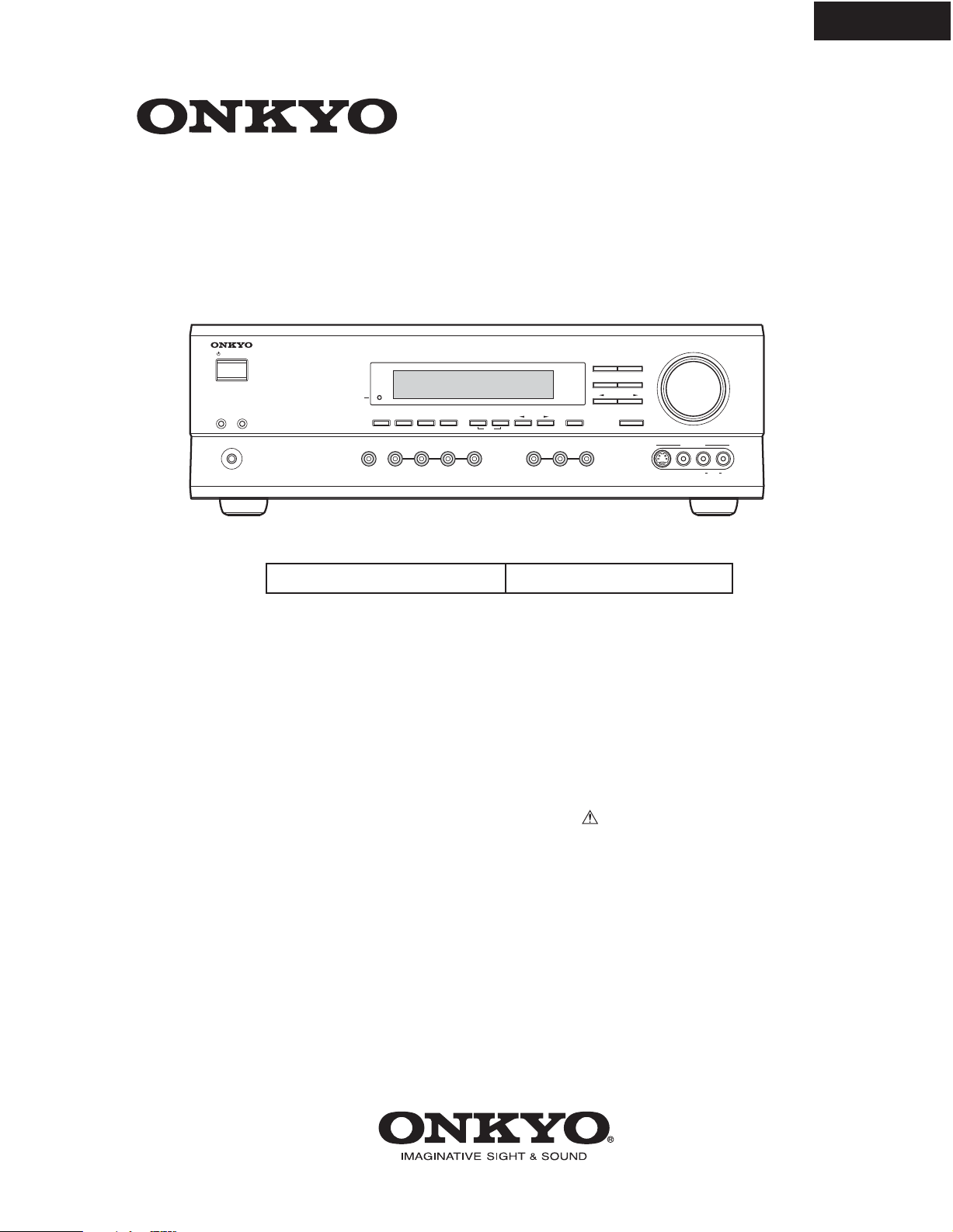
AV RECEIVER
MODEL HT-R510
HT-R510
Ref. No. 3778
062003
STANDBY/ON
SPEAKERS
AB
PHONES
BMDD
STEREO
DIRECT
DSP
SURROUND
STANDB
Y
AUDIO
SELECTOR
SUBWOOFER
DIGITAL INPUT
DIMMER
DISPLA
Y
DVD
VIDEO 1
MODE
VIDEO 2
VCR
VIDEO 3
MEMORY
FM MODE
CLEAR
TUNING
TAPE TUNER
SPEAKER ADJUST
PRESET/ADJUST
AUDIO ADJUST
C
D
S VIDEO AUDIO
Black models
120V AC, 60Hz
SAFETY-RELATED COMPONENT
WARNING!!
COMPONENTS IDENTIFIED BY MARK ON THE
SCHEMATIC DIAGRAM AND IN THE PARTS LIST ARE
CRITICAL FOR RISK OF FIRE AND ELECTRIC SHOCK.
REPLACE THESE COMPONENTS WITH ONKYO
PARTS WHOSE PART NUMBERS APPEAR AS SHOWN
IN THIS MANUAL.
MAKE LEAKAGE-CURRENT OR RESISTANCE
MEASUREMENTS TO DETERMINE THAT EXPOSED
PARTS ARE ACCEPTABLY INSULATED FROM THE
SUPPLY CIRCUIT BEFORE RETURNING THE
APPLIANCE TO THE CUSTOMER.
MASTER VOLUME
INPUT
VIDEO 3
VIDEO L
R
Page 2

SERVICE PROCEDURES
1. Replacing the fuses
This symbol located near the fuses indicates that the
fuse used is fast operating type. For continued protection against
fire hazard, replace with same type fuse. For fuse rating refer to
the marking adjacent to the symbol.
Ce symbole indique que le fusible utlise est a rapide.
Pour une protection permanente, n'untiliser que fusibles de
meme type. Ce darnier est la qu le present symbol est
appse.
CIRCUIT NO. PART NO.
F6901,F6902 252198 or ! 8A-UL or
252261 ! 8A-T/UL-ST2,Fuse
F901 252198 or ! 8A-UL or
252261 !
2. To initialize the unit
This device employs a microprocessor to perform various
functions and operations. If interference generated by an external
power supply, radio wave, or other electrical source results in
accident which causes the specified operations and functions to
operate abnormally.
To perform a result, please follow the procedure below.
DESCRIPTION
8A-T/UL-ST2,Fuse
HT-R510
1.Press and hold down the VIDEO-1 button, then press the
STANDBY/ON button.
2.After "CLEAR" is displayed, the preset memory and each
mode stored in the memory, such as surround, are
initialized and will return to the factory setting.
3. Unplug the power supply cord.
3. Safety-check out
(U.S.A. model only)
After correcting the original service problem, perform the
following safety check before releasing the set to the customer.
Leakage Current Check
Measure leakage current to a known earth ground(water pipe,
conduit, etc.) by connecting a leakage current tester between
the earth ground and exposed metal parts of the appliance
(input/output terminals, screwheads,metal overlays, etc.).
Plug the power supply cord directly into a 120V AC 60 Hz outlet
and turn Standby switch on. Any current meausred must not
exceed 0.5mA.
Page 3

EXPLODED VIEW
HT-R510
33
11
U24
P901
U23
T901
33
F901
63
33
2
U31
P101
U9
31
U15
U14
U10
U27
U28
2
F6901
F6902
Q6050
Q6060
9
9
U21
U13
13
2
Q6055
5
U26
Q6065
55
2
12
U17
U1
54
2
2
U12
10
U4
P7503
2
17
17
P7502
U3
U6
17
16
18
1
2
51
U25
21
22
23
56
52
25
53
53
24
HT-R510
6
8
8
7
21
22
23
U5
2
Page 4

HT-R510
ID+
3
b
8
WIRING VIEW
1
2
7
P911A
3
NAPS-7844,
Transformer
terminal
PC board ass'y
4
P912A
U23
P913A
5
3
1
A
P926
E921
P911
P908
AC-G
AC-GAC-H
AC-H
P909
P901A
T901
POWER
TRANSFORMER
NPT-1465D
NAPS-7846,
Secondary
terminal
PC board ass'y
P902
P918
P912
P922
P921
NAETC-7835,Speaker
terminal PC board ass'y
NAPS-7845,Primary circuit
U24
PC board ass'y
P917
P913
P923
120V
P922A
S902
220V
P923A
T902
P925
P921A
P931A
NAETC-7834,
Secondary
PC board ass'y
JL9501B
141312111098
15 16 17 18 19
JL6952B
JL6951B
U25
BCD
U2
P6931A
U13
P6801
JL6803B
U14
JL6805B
P6802
JL6804B
P6800
NCETC-7835
P6906
P931
P6907
C6708
D6705
P6910
D6706
P995B
P997A
P6909
JL6952A
JL6951A
P996A
JL6805A
U21
NAAF-7842,
P6923
P6922
P995A
P6801
P6301
JL640
P6000
JL6804A
P6903
P6011A
COM
TH2
TH1
P6001
P6073A
P6002
P6802
JL6803A
2A
R6040
L
ID+
ID-
P6080
-B1
R6041
R
ID-ID+
P6081
R6042
ID+
ID-
P6082
Power amplifier
PC board ass'y
P6072
P6072A
P6003
P6004
P6005
R6043
P6083
ID-ID+
R6044
ID-
ID+
P6084
R6045
ID-
ID+
P6085
P6931
NAETC-78
circuit PC
JL9501
U4
NCSW-7404
NASW-7404,
Standby switch
PC board ass'y
U5
JL7501B
JL7501A
NAETC-7405,
5
Headphone
terminal PC
board ass'y
JL7502B
P7501
JL7502A
NADIS-7403,Display circui
U3
Page 5

HT-R510
WIRING VIEW
U28
1
2
3
NAETC-7849,
Thermal detector
PC board ass'y
JL6402B
P6000A
U9
P6011A
P6001A
P6002A
NAAF-7830,
Driver circuit
PC board ass'y
P6003A
P6004A
A
P306A
BCD
U6
V4Y
GND
V4C
GND
P302
P304P305
P301
P351
U17
P261B
V4
P253B
NAETC-7838,
Connector PC
board ass'y
P801B
P801
P7701
P7701
P206A
P243A
P206B
U283
P253A
U282
U1
NADG-7821,
DSP circuit
PC board ass'y
P306
P7502B
P412B
P261A
P101
NAETC-7406,
Front video
PC board ass'y
U26
NAVD-7847,Video
circuit PC board ass'y
P281
U281
P282
P243B
P241
P201
P242A
U10
NAVD-7831,Component
video PC board ass'y
P203
P202
P204
P6005A
U12
4
-7833,Const. voltage
C board ass'y
5
ircuit PC board ass'y
P7503B
GND
GND
HPL
HPE
HPR
+5.6V
FLAC
FLAC
P7503A
P410B
P7502A
P410A
P411B
P411A
P6403
TUNER
U31
PAC K
: Flat cable
: Jumper Wire
: Socket
: PC board to PC board
 Loading...