

Page 1
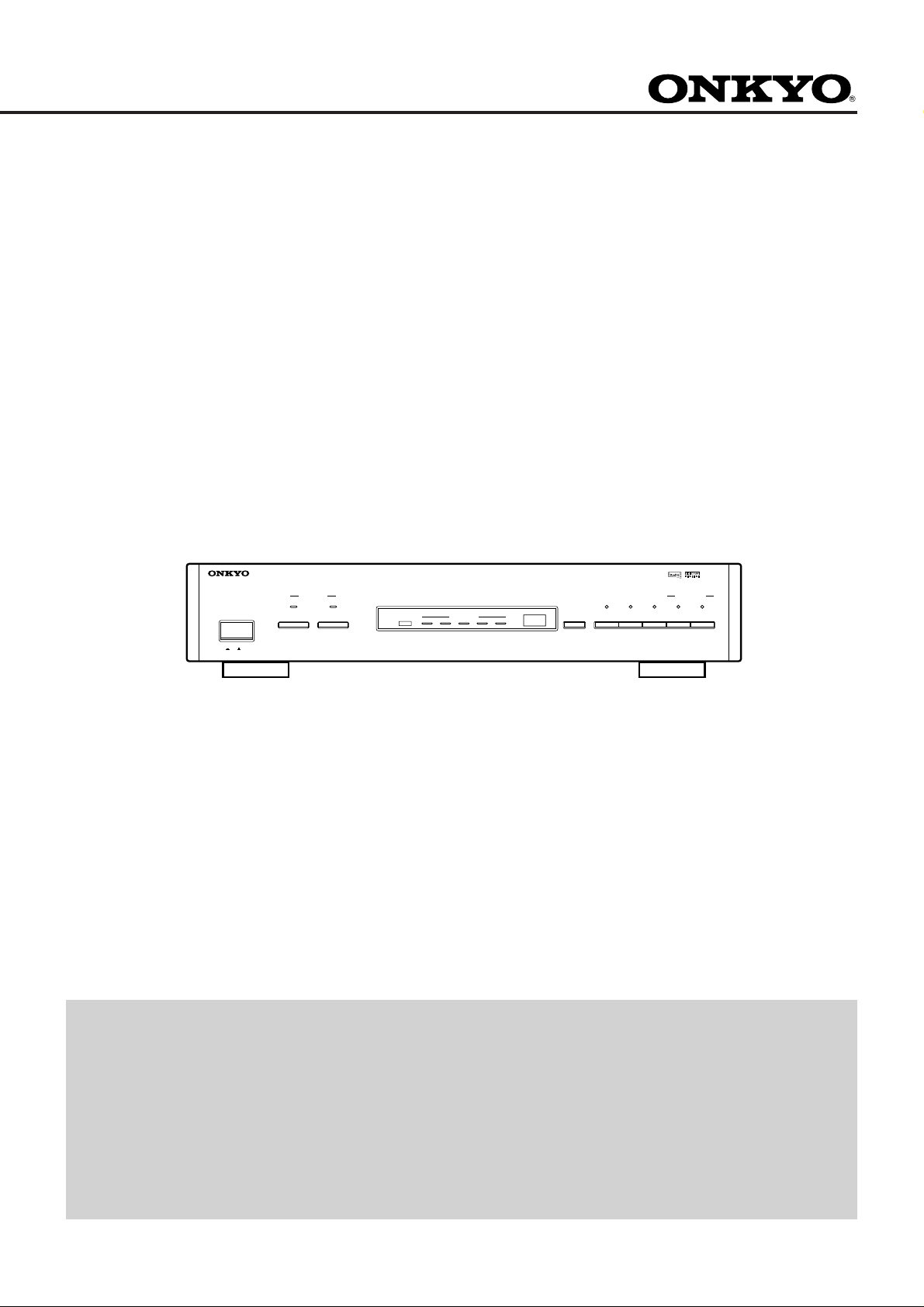
ED-901
Dolby surr ound AC-3 Decoder
Instruction Manual
DOLBY SURROUND AC-3 DECODER
POWER
ON
OFF
INPUT SELECTOR
INPUT 1 (VDP) INPUT 2 (DVD)
PROGRAM STATUS
R
AC-3
LS RSCL
mSEC.
ON ON −10dB C S
DELAY TIME CINEMA Re-EQ MIDNIGHT THEATER CENTER SURROUND
OUTPUT CH. MODE
LEF LEVEL
ED-901
CONTENTS
Features................................................ 2
Important Safeguards........................... 3
Precautions .......................................... 4
Introduction ......................................... 5
Speaker Placement............................... 6
Control Positions and Names .............. 7
Connections ......................................... 8
Operations............................................ 9
Block Diagram................................... 13
Troubleshooting Guide ...................... 14
Specifications .................................... 15
Page 2
Thank you for your purchase of the
ONKYO ED-901 Dolby Surround AC-3 Decorder.
Please read this manual thoroughly before making connections
and plugging in the AC power cord.
Following the instructions in this manual will enable you to
obtain optimum performance and maximum listening enjoyment from your new ED-901.
Please retain this manual for future reference.
Features
AC-3 Decorder with Lucas Film Cinema ReEQ
LFE (Low Frequency Effects) Level Control
(0dB or -10dB)
Midnight Theater for late night listening at
low volume
2-Input (VDP/DVD)
FOR CANADIAN MODEL:
(POUR LE MODELE CANADIEN)
• For models having a power cord with a polarized plug
CAUTION :TO PREVENT ELECTRIC SHOCK, MATCH
WIDE BLADE OF PLUG TOWIDE SLOT, FULLY INSERT.
• THIS DIGITAL APPARATUS DOES NOT EXCEED THE
CLASS B LIMITS FOR RADIO NOISE EMISSION FROM
DIGITAL APPARATUS SET OUT IN THE
RADIOINTERFERENCE REGULATIONS OF THE
CANADIAN DEPARTMENT OF COMMUNICATIONS.
• Sur les modèles dont la fiche est polarisée.
ATTENTION: POUR ÉVITER LES CHOCS ÉLECTRI-
QUES, INTRODUIRE LA LAME LA PLUS LARGE DE LA
FICHE DANS LA BORNE CORRESPONDANTE DE LA
PRISE ET POUSSER JUSQ’AU FOND.
• L'INTERFERENCE, RADIO ELECTRIQUE GENEREE
PAR CET APPAREIL NUMERIQUE DE TYPE B NE
DEPASSE PAS LES LIMITES ENONCEES DANS LE
REGLEMENT SUL LES PERTURBATIONS RADIO
ELECTRIQUES, SECTION APPAREIL NUMERIQUE, DU
MINISTERE DES COMMUNICATIONS.
ATTENTION FOR BRITISH MODEL
• Replacement and mounting of an AC plug on the power
supply cord of this unit should be performed only by qualified
service personnel.
• IMPORTANT: The wires in the mains lead are coloured in
accordance with the following code:
Blue: Neutral
Brown: Live
As the colours of the wires in the mains lead of this apparatus
may not correspond with the coloured markings identifying the
terminals in your plug, proceed as follows:
The wire which is coloured blue must be connected to the
terminal which is marked with the letter N or coloured black.
The wire which is coloured brown must be connected to the
terminal which is marked with the letter L or coloured red.
Declaration of Conformity
We,
ONKYO EUROPE
ELECTRONICS GMBH
INDUSTRIESTRASSE 18/20
82110 GERMERING,
GERMANY
declare in own responsibility, that the ONKYO product described
in this instruction manual is in compliance with the corresponding
technical standards such as EN55013, EN55020, EN60555-2, -3
and EN60065
GERMERING,GERMANY
H. YAMAZOE
ONKYO EUROPE ELECTRONICS GMBH
FOR U.S.A. MODEL:
FCC INFORMATION FOR USER
CAUTION:
Changes or modifications not expressly approved by the
manufacturer for compliance could void the user’s authority
to operate the equipment.
NOTE:
This equipment has been tested and found to comply with the
limits for a Class B digital device, pursuant to Part 15 of the
FCC Rules. These limits are designed to provide reasonable
protection against harmful interference in a residential
installation. This equipment generates, uses, and can radiate
radio frequency energy and, if not installed and used in
accordance with the instructions, may cause harmful interference to radio communications. However, there is no guarantee that interference will not occur in a particular installation.
If this equipment does cause harmful interference to radio or
television reception, which can be determined by turning the
equipment off and on, the user is encouraged to try to correct
the interference by one or more of the following measures:
• Reorient or relocate the receiving antenna.
• Increase the separation between the equipment and receiver.
• Connect the equipment into an outlet on a circuit different
from that to which the receiver is connected.
• Consult the dealer or an experienced radio/TV technician
for help.
• The lightning flash with arrowhead symbol, within
an equilateral triangle, is intended to alert the user to
the presence of uninsulated “dangerous voltage”
within the product’s enclosure that may be of
sufficient magnitude to constitute a risk of electric
shock to persons.
• The exclamation point within an equilateral triangle
is intended to alert the user to the presence of
important operating and maintenance (servicing)
instructions in the literature accompanying the
appliance.
WARNING
“TO REDUCE THE RISK OF FIRE OR ELECTRIC
SHOCK, DO NOT EXPOSE THIS APPLIANCE TO RAIN
OR MOISTURE.”
CAUTION
“TO REDUCE THE RISK OF ELECTRIC SHOCK, DO NOT
REMOVE COVER (OR BACK). NO USER-SERVICEABLE
PARTS INSIDE. REFER SERVICING TO QUALIFIED
SERVICE PERSONNEL.”
CAUTION
RISK OF ELECTRIC SHOCK
DO NOT OPEN
2
Page 3

Important Safeguards
1. Read Instructions — All the safety and operating instructions
should be read before the appliance is operated.
2. Retain Instructions — The safety and operating instructions
should be retained for future reference.
3. Heed Warnings — All warnings on the appliance and in the
operating instructions should be adhered to.
4. Follow Instructions — All operating and use instructions should
be followed.
5. Water and Moisture — The appliance should not be used near
water — for example, near a bathtub, washbowl, kitchen sink,
laundry tub, in a wet basement; or near a swimming pool, and the
like.
6. Carts and Stands — The appliance should be used only with a
cart or stand that is recommended by the manufacturer.
6A. An appliance and cart combination should be moved with care. Quick
stops, excessive force, and uneven surface may cause the appliance
and cart combination to overturn.
7. Wall or Ceiling Mounting — The appliance should be mounted
to a wall or ceiling only as recommended by the manufacturer.
8. Ventilation — The appliance should be situated so that its
location or position does not interfere with its proper ventilation.
For example, the appliance should not be situated on a bed, sofa,
rug, or similar surface that may block the ventilation openings; or if
placed in a built-in installation, such as a book case or cabinet that
may impede the flow of air through the ventilation openings, there
should be free space of at least 20 cm (8 in.) and open up behind the
appliance.
9. Heat — The appliance should be situated away from heat sources
such as radiators, heat registers, stoves, or other appliances (including
amplifiers) that produce heat.
10. Power Sources — The appliance should be connected to a power
supply only of the type described in the operating instructions or as
marked on the appliance.
11. Polarization — The polarization of the plug is a safety feature. The
polarized plug will only fit the outlet one way. If the plug does not fit
fully into the outlet, try reversing it. If there is still trouble, the user
should seek the services of a qualified electrician. Under no
circumstances should the user attempt to defeat the polarization of the
plug.
12. Power-Cord Protection — Power-supply cords should be routed
so that they are not likely to be walked on or pinched by items placed
upon or against them, convenience receptacles, and the point where
they exit from the appliance.
13. Cleaning — The appliance should be cleaned only as recom-
mended by the manufacturer.
14. Nonuse Periods — The power cord of the appliance should be
unplugged from the outlet when left unused for a long period of time.
15. Object and Liquid Entry — Care should be taken so that objects
do not fall and liquids are not spilled into the enclosure through
openings.
16. Damage Requiring Service — The appliance should be serviced
by qualified service personnel when:
A. The power-supply cord or the plug has been damaged; or
B. Objects have fallen, or liquid has been spilled into the appliance;
or
C. The appliance has been exposed to rain; or
D. The appliance does not appear to operate normally or exhibits a
marked change in performance; or
E. The appliance has been dropped, or the enclosure damaged.
17. Servicing — The user should not attempt to service the appliance
beyond that described in the operating instructions. All other
servicing should be referred to qualified service personnel.
PORTABLE CART WARNING
S3125A
3
Page 4

Precautions
1. Warranty card
The serial number is written on the rear panel of the unit.
Write the serial number and model number on your warranty
card and keep it in a safe place.
2. Recording Copyright
Recording of copyrighted material for other than personal use
is illegal without permission of the copyright holder.
3. AC fuse
The fuse is located inside the chassis and is not user service-
able. If power does not come on, contact your ONKYO
service center.
4. Care
From time to time you should wipe off the front and rear
panels and the cabinet with a soft cloth. For heavier dirt,
dampen a soft cloth in a weak solution of mild detergent and
water, wring it out, and wipe away the dirt. Following this,
dry immediately with a clean cloth. Do not use rough
material, thinners, alcohol or other chemical solvents or
cloths since these may damage the finish or remove the panel
lettering.
5. Power
WARNING
BEFORE PLUGGING IN THE UNIT FOR THE
FIRST TIME, READ THE FOLLOWING SECTION
CAREFULLY.
• Some models are designed for use only with the power supply
voltage of the region where they are sold.
European model: AC 230 V, 50 Hz
U.S.A. and Canadian models: AC 120 V, 60 Hz
4
Page 5

Introduction
Onkyo’s ED-901 Dolby Surround AC-3 Decoder brings your home the excitement of Dolby Surround AC-3 sound effects from your
LaserDiscs, etc. that employ the latest Dolby AC-3 technology. The ED-901 consists of an AC-3RF demodulator, an AC-3 decoder, and
a Cinema Re-EQ circuit.
An ideal AC-3 home theater system may include either an Onkyo TX-SV919THX or TX-SV828THX surround receiver. These receivers
can be connected to the ED-901 through the DB-25 connector.
What is Dolby Surround AC-3?
· Dolby Surround AC-3 is a new-generation digital audio format for multi-channel surround audio. With this digital audio format, you
can create a five full-range channel system called a “3/2” channel surround system (left, center, right, and two surround channels),
which is a developed version of the conventional “3/1” channel surround system” (left, center, right, and only one surround channel).
· Adding to its five full range channels, Dolby Surround AC-3 supports an LFE (low frequency effect) channel, which is used solely
for low frequency sounds independent of the other channels. Dolby Surround AC-3 is sometimes referred to as a “5.1” channel
format since this LFE channel is indicated as 0.1.
· This fully discrete 5.1 channel Dolby Surround AC-3 can reproduce sound of wide and dynamic range, changing your room into a
home theater.
· Currently, LaserDisc is the only medium that employs the Dolby Surround AC-3 technology. In the near future, however, Dolby
Surround AC-3 will be implemented in such media as DVD (Digital Video Disc), CATV (Cable Television), DBS (Direct Broadcasting), and HDTV (High Definition Television).
Dolby Surronud AC-3
Manufactured under license from Dolby Laboratories Licensing Corporation. “Dolby”, “AC-3”, and the double-D symbol are trademarks
of Dolby Laboratories Licensing Corporation.
Copyright 1992 Dolby Laboratories, Inc. All rights reserved.
5
Page 6

Speaker Placement
Speaker Placement
We recommend that you use the ED-901 in conjunction with the Onkyo TX-SV919THX or TX-SV828THX surround receiver. If you
have a complete THX speaker system that is connected to either of these receivers, the addition of new speakers or arrangement of the
current speaker configuration is unnecessary.
If you do not have a complete THX speaker system...
The highest quality Dolby Surround AC-3 sound can be reproduced when the ED-901 is connected to five full range THX speakers and
one or more subwoofers. To get the most out of the ED-901, it is strongly recommended that you set-up a complete THX speaker system.
To use ED-901 without a complete THX speaker system...
If no Center speaker or Surround speaker is connected to your system, the sound to the unused channel can be properly distributed to
other channels.
To do so, turn off the indicator corresponding to the unused channel by pressing the CENTER button or SURROUND button on the front
panel (see page 10).
Note:
You must make the similar setting on your TX-SV919THX or TX-SV828THX surround receiver. See the Receiver Instruction Manual.
<Fig. Speaker Placement>
Front Left
Subwoofer
Left Surround Right Surround
Front Right
Front Left
Center
Right Surround
Front Right
Front Left
Subwoofer
Left Surround Right Surround
Center
Front Right
Center
Subwoofer
Left Surround
6
Page 7

Control Positions and Names
NOTE:
If there is a protective film on the surface of the display, making it difficult to read the display, remove it.
For more information about the function of a particular button, please turn to the page listed in the brackets ([ ]) following each name.
11
10
9
8
1234 5
DOLBY SURROUND AC-3 DECODER
INPUT SELECTOR
POWER
INPUT 1 (VDP) INPUT 2 (DVD)
ON
OFF
PROGRAM STATUS
R
AC-3
LS RSCL
7
6
ON ON −10dB C S
DELAY TIME CINEMA Re-EQ MIDNIGHT THEATER CENTER SURROUND
mSEC.
LEFT LEVEL
OUTPUT CH. MODE
ED-901
Front panel
1. POWER button [9]
2. INPUT1 (VDP) Input Selector [9]
3. INPUT2 (DVD) Input Selector [9]
4. AC-3 indicator
This LED lights if you play AC-3 compatible software.
5. PROGRAM STATUS indicators
These LEDs indicate which output channels the software
uses.
6. DELAY TIME button and indicator [11]
7. CINEMA Re-EQ button and indicator [12]
8. MIDNIGHT THEATER button and indicator [12]
9. LFE LEVEL button and indicator [12]
10. CENTER button and indicator [10]
11. SURROUND button and indicator [10]
Supplied accessories
Audio connection cable (1) Video/Digital (Coaxial) connection cable
(2)
DB-25 cord (1)
7
Page 8

Connections
· Do not plug in the power cord until all connections have been made.
· Before connecting the ED-901 to the receiver, make sure that the POWER switches on both the ED-901 and the receiver are in the
OFF position.
· On each pair of input jacks, the lower jack (marked R: Red) corresponds to the right channel and the upper jack (marked L: White) to
the left channel.
· Be sure to read the Receiver Instruction Manual in addition to this manual.
For connection to the Onkyo TX-SV919THX surround
receiver...
· Connect the other end of the video cable (supplied) to the
VIDEO-4 IN terminal of the TX-SV919THX.
· On the TX-SV919THX, set the External Decoder mode to
“ON”.
See the “Setting External Decoder Parameter” section (page
55) of the TX-SV919THX Manual and set the parameters set
by "Level Calibration (TEST TONE)..."(page 33), because
External decoder parameters are able to be set independently
from THX mode parameters.
VDP DVD
Note:
VDP with AC-3RF output is
required for AC-3 reproduction.
S video
AC-3RF
OUT
Audio
out
L R
Video
OUT
For connection to the Onkyo TX-SV828THX surround
receiver...
· Connect the other end of the video cable (supplied) to the
VIDEO-1 IN terminal of the TX-SV828THX.
· Read “AC-3 decoder connection” in the “Optical preamplifier connections” section of the TX-SV828THX
Manual.
· On the TX-SV828THX, select “External Decoder” in the
Surround Setup menu. See Fig. 4 in the “Operating Surround” section (page 42) of the TX-SV828THX Manual.
Coaxial
OUT
Optical
OUT
S video
OUT
Video
OUT
Audio
out
L R
R L VideoS-Video
VIDEO-4
IN
External
decorder
input
VIDEO-4 IN
(TX-SV919THX)
INPUT 2
(DVD)
COAXIAL OPTICAL
Note:
Fasten the screws
with a screwdriver
to secure
the connections.
COAXIAL
DB-25 cable
(included)
External decorder input
S
VIDEO-1
IN
V
IN
L
R
VIDEO-1
VIDEO-1 IN
(TX-SV828THX)
OPTICAL
INPUT 1
(VDP)
AC-3 RF
S cable
(option)
ED-901
MULTI-CHANNEL AUDIO OUTPUT
DB-25
OUTPUT INPUT INPUT 2
Audio cable
(included)
OUTPUT INPUT INPUT 2
S-VIDEO
AUDIO
L
R
Video cable
(included)
VIDEO
DOLBY SURROUND AC-3 DECODER
MODEL NO. ED-901
RATING:
AC120V 60Hz 25W
ONKYO CORPORATION
2-1,NISSHIN-CHO,NEYAGAWA-SHI,OSAKA,
JAPAN
MADE IN JAPAN
TX-SV828THX or TX-SV919THX
Plug in the AC
power cord to a
wall outlet if
you have
connected all the
other cables.
8
Page 9

Operation
Note:
• Before performing the following procedure, make sure that the
ED-901 is properly connected to the surround receiver.
• To play Dolby Pro Logic sound sources...
The ED-901 is not equipped with a Dolby Pro Logic decoder.
To play Dolby Pro Logic sound sources, connect the ED-901 to
your receiver by audio cables and set the receiver's Input
Selector to Analog Input ("VIDEO-4" for the TX-SV919THX
and "VIDEO-1" for the TX-SV828THX).
3
POWER
ON OFF
4
INPUT 1 (VDP)
INPUT 2 (DVD)
3
4
1. Turn on the power of the surround receiver.
Perform the necessary settings, such as
adjusting output level of each channel,
on the surround receiver.
See the instruction manual of your
surround receiver for details.
2. Set the surround receiver’s Input
Selector as follows:
TX-SV919THX: “VIDEO-4”
TX-SV828THX: “VIDEO-1”
Then, select the External Decoder mode
on the surround receiver.
(See also "For connection to the Onkyo
TX-SV919THX/TX-SV828THX
surround receiver..." on page 8.)
3. Press the POWER button on the
ED-901 to turn it on.
4. Press the INPUT 1 (VDP) or
INPUT 2 (DVD) input selector
button.
The LED for the selected input source
will light.
5. Play the AC-3 sound source.
The PROGRAM STATUS indicator
will appear on the display.
9
Page 10

Operation
Output Channel Mode
Setting the Output Channel Mode
(OUTPUT CH. MODE)
· The highest quality Dolby Surround
AC-3 sound can be reproduced when
the ED-901 is connected to five fullrange THX speakers and one or more
subwoofers. To get the most out of the
ED-901, it is strongly recommended
that you set-up a complete THX
speaker system.
· If no Center speaker or Surround
speaker is connected to your system,
the sound to the unused channel can be
properly distributed to other channels:
C
CENTER
S
SURROUND
turn off
turn off
If Center speaker is not connected...
Turn off the C indicator by pressing the
CENTER button.
If Surround speakers are not connected...
Turn off the S indicator by pressing the
SURROUND button.
Note:
Setting the Output Channel mode on the
ED-901 does not change the Speaker Mode
setting of the surround receiver (TXSV919THX or TX-SV828THX). Be sure to
set the surround receiver properly according to the instructions in the Receiver
Instruction Manual.
10
Page 11

DELAY TIME
Setting the Surround Delay
For Dolby Surround AC-3, as opposed to
the conventional Dolby Pro Logic technology, it is unnecessary to set the time delay
between front speakers and surround
speakers. The only thing you should
consider is the difference between the front
speaker-listener distance and surround
speaker-listener distance.
1. Press the DELAY TIME button
repeatedly until the desired
delay time is displayed.
Operation
mSEC.
DELAY TIME
The factory-set default is 5 ms (milliseconds). Each time the DELAY TIME button
is pressed, the time increases by 1 ms. You
can set a delay time within the range of 0
to 15 ms.
A rule of thumb is that it takes 1 ms for
sound to travel one foot. For example, if
the front speakers and the surround
speakers are located the same distance
from the listening position, you should set
the delay time as “0”; If the front speakerlistener distance is one foot longer, set the
delay time to “1 ms” and so on.
Note:
· If your surround receiver’s delay time
has been accurately set for Dolby Pro
Logic Surround play, make the ED901’s delay time 15 ms shorter than
that time.
· If you have changed the speaker
arrangement, change the speaker
output setting as appropriate both on
the ED-901 and on the surround
receiver. The settings of these two are
independent of each other.
11
Page 12

Operation
Re-EQ is licensed from Lucasfilm, Ltd. U.S. patent numbers 5,043,970; 5,189,703; 5,222,059. Foreign patents pending. Lucasfilm and
Re-EQ are trademarks of Lucasfilm Ltd.
MIDNIGHT TEATER
LFE LEVEL
CINEMA Re-EQ
Using the Cinema Re-EQ, Midnight Theater and LFE Modes
Using the Cinema Re-EQ Mode
Press the CINEMA Re-EQ button. The
LED indicator (ON) immediately above
this button will light to indicate that you are
ON
CINEMA Re-EQ
ON
MIDNIGHT THEATER
−10dB
LFE LEVEL
in the CINEMA Re-EQ mode.
· Use the Cinema Re-EQ mode if your
system is placed in a small room.
Motion pictures are produced on the
assumption that they will be shown at a
large cinema. If they are shown in a
small room, however, high-frequency
range sound will be raised, resulting in
uncomfortable sound. In the Cinema
Re-EQ mode, however, the ED-901
compensates this and reproduces
optimal sound for the home theater
system.
Using the Midnight Theater Mode
Press the MIDNIGHT THEATER button.
The LED indicator (ON) immediately
above this button will light to indicate that
you are in the Midnight Theater mode.
· Use the Midnight Theater mode if you
must play a movie at low sound volume
at night. In the Midnight Theater mode,
the ED-901 makes the dynamic range
of the reproduced sound narrower for
easy-to-hear sound.
Setting the LFE Mode
Press the LFE LEVEL button. The LED
indicator (-10dB) immediately above this
button will light to indicate that the LFE
(Low Frequency Effect) circuit is enabled.
· Use the LFE mode if the bass reproduced is too loud. In the LFE mode,
the ED-901 decreases the reproduced
sound in the low-frequency channel by
10 dB.
12
Page 13

Block Diagram
VDP
DVD
AC - RF
OPTICAL
COAXIAL
AC - 3 RF
Demodulator
Digital Audio Interface
AC-3 Decoder
20 bit
D/A
20 bit
D/A
20 bit
D/A
L
R
Anti-aliasing Filter
LS
RS
C
+10dB
LFE
CINEMA Re-EQ
DB-25 OUTPUT
SUB-WOOFER
VDP
VIDEO
DVD
VIDEO
VDP
DVD
S
S
L
R
L
R
VIDEO SELECTOR
VIDEO OUTPUT
S
Composite
VIDEO
AUDIO SELECTOR
AUDIO OUTPUT
L
R
13
Page 14

Troubleshooting Guide
• No power.
Cause: Power cord is not plugged in or is not com-
pletely inserted.
Remedy: Firmly plug in the power cord.
• No Sound.
Cause: Incorrect cord connections.
Remedy: Connect the cord properly.
Cause: Wrong input selector.
Remedy: Select the proper input.
Cause: Wrong position of coaxial/optical selector.
Remedy: Select the proper position.
Cause: Wrong input mode selection on the receiver.
Remedy: Select the proper mode on the receiver.
• No Sound from Center or Surround Speakers.
Cause: Wrong OUTPUT CH. MODE selection.
Remedy: Put on the OUTPUT CH. MODE
indicator for the
speaker.
• No Sound from Subwoofer.
Cause: No Subwoofer is selected on the receiver.
Remedy: Select Subwoofer on the receiver.
• Low Frequency Noise, Hum.
Cause: Incorrect audio cord connection.
Remedy: Firmly connect audio cords.
• Poor Bass Sound.
Cause: LFE LEVEL setting is -10dB.
Remedy: Put off the LFE LEVEL indicator.
• The Difference of Sound Level between Channels.
Cause: Incorrect volume level adjustment on the
receiver.
Remedy: Adjust volume level for each Channel
properly.
• Noise from/to nearby TV or Tuner.
Cause: This unit is too close to the affected equipment.
Remedy: Move this unit or the affected equipment
far from each other.
14
Page 15

Specifications
Input Seneitivity: INPUT-1,2 analog audio: 50kΩ
and Impedance INPUT-1 AC-3RF: 75Ω
INPUT-2digital (coaxial): 75Ω
INPUT-1,2video: 1Vp-p/75Ω
S-video Y: 1Vp-p/75Ω
S-video C: 0.28Vp-p/75Ω
Output Level: D-SUB25 5.1CH OUTPUT
and Impedance LEFT, RIGHT, CENTER,
LEFT SURROUND, RIGHT SURROUND
(SUB WOOFER) : 0.2V/470Ω
Frequency response: Dolby AC-3 5CH out 20 Hz - 20 kHz+0/-3dB
Distortion: L/C/R/LS/RS: 0.05%/1kHz
SUBWOOFER: 0.05%/50Hz
Signal to noise ratio:
Power consumption: 25 watts
Power supply rating: USA and Canadian models:
AC 120 V, 60 Hz
European model:
AC 230 V, 50 Hz
Dimensions (W × H × D): 455 × 90 × 320 mm
(17-15/16" × 3-9/16" × 12-5/8")
Weight: 4.3 kg, (9.5 lbs.)
Specifications and external appearance are subject to change without notice because of product improvements.
98dB (Output=2v)(IHF-A)
15
Page 16

Sales Planning & Promotion Dept.: 2-1, Nisshin-cho, Neyagawa-shi, OSAKA 572, JAPAN
http://www.onkyo.co.jp/
HOMEPAGE
Tel: 0720-31-8111 Fax: 0720-33-5222
ONKYO U.S.A. CORPORATION
200 Williams Drive, Ramsey, N.J. 07446, U.S.A.
Tel: 201-825-7950 Fax: 201-825-8150 E-mail: onkyo@onkyousa. com
ONKYO EUROPE ELECTRONICS GmbH
Industriestrasse 18-20, 82110 Germering, GERMANY
Tel: 089 84 93 20 Fax: 089 84 93 226
ONKYO FRANCE
Immeuble Le Diamant, Domaine Technologique de Saclay, 4 Rue René Razel,
91892 SACLAY, FRANCE Tel: (1) 69 33 14 00 Fax: (1) 69 41 35 84
SN29342251
Printed in Japan
E
 Loading...